

Yamaha HTR-5730 Owners Manual

HTR-5730
AV Receiver
Ampli-tuner audio-vidéo
G
OWNER’S MANUAL
MODE D’EMPLOI
BEDIENUNGSANLEITUNG
BRUKSANVISNING
GEBRUIKSAANWIJZING
ИНСТРУКЦИЯ ПО ЭКСПЛУАТАЦИИ

CAUTION: READ THIS BEFORE OPERATING YOUR UNIT.
1 To assure the finest performance, please read this
manual carefully. Keep it in a safe place for future
reference.
2 Install this sound system in a well ventilated, cool,
dry, clean place — away from direct sunlight, heat
sources, vibration, dust, moisture, and/or cold.
Allow ventilation space of at least 30 cm on the top,
20 cm on the left and right, and 20 cm on the back
of this unit.
3 Locate this unit away from other electrical
appliances, motors, or transformers to avoid
humming sounds.
4
Do not expose this unit to sudden temperature
changes from cold to hot, and do not locate this unit
in a environment with high humidity (i.e. a room with
a humidifier) to prevent condensation inside this unit,
which may cause an electrical shock, fire, damage to
this unit, and/or personal injury.
5 Avoid installing this unit where foreign object may
fall onto this unit and/or this unit may be exposed
to liquid dripping or splashing. On the top of this
unit, do not place:
– Other components, as they may cause damage
and/or discoloration on the surface of this unit.
–
Burning objects (i.e. candles), as they may cause
fire, damage to this unit, and/or personal injury.
– Containers with liquid in them, as they may fall
and liquid may cause electrical shock to the
user and/or damage to this unit.
6 Do not cover this unit with a newspaper, tablecloth,
curtain, etc. in order not to obstruct heat radiation.
If the temperature inside this unit rises, it may
cause fire, damage to this unit, and/or personal
injury.
7 Do not plug in this unit to a wall outlet until all
connections are complete.
8 Do not operate this unit upside-down. It may
overheat, possibly causing damage.
9 Do not use force on switches, knobs and/or cords.
10 When disconnecting the power cord from the wall
outlet, grasp the plug; do not pull the cord.
11 Do not clean this unit with chemical solvents; this
might damage the finish. Use a clean, dry cloth.
12 Only voltage specified on this unit must be used.
Using this unit with a higher voltage than specified
is dangerous and may cause fire, damage to this
unit, and/or personal injury. YAMAHA will not be
held responsible for any damage resulting from use
of this unit with a voltage other than specified.
13
To prevent damage by lightning, disconnect the power
cord from the wall outlet during an electrical storm.
14 Do not attempt to modify or fix this unit. Contact
qualified YAMAHA service personnel when any
service is needed. The cabinet should never be
opened for any reasons.
15 When not planning to use this unit for long periods
of time (i.e. vacation), disconnect the AC power
plug from the wall outlet.
16 Be sure to read the “TROUBLESHOOTING” section
on common operating errors before concluding that
this unit is faulty.
17 Before moving this unit, press STANDBY/ON to set
this unit in standby mode, and disconnect the AC
power plug from the wall outlet.
18
VOLTAGE SELECTOR (Asia and Greneral models only)
The VOLTAGE SELECTOR on the rear panel of this
unit must be set for your local main voltage
BEFORE plugging into the AC main supply.
Voltages are 110V-120V, 220V-240V AC, 50/60 Hz.
This unit is not disconnected from the AC power
source as long as it is connected to the wall outlet,
even if this unit itself is turned off. This state is called
standby mode. In this state, this unit is designed to
consume a very small quantity of power.
WARNING
TO REDUCE THE RISK OF FIRE OR ELECTRIC
SHOCK, DO NOT EXPOSE THIS UNIT TO RAIN
OR MOISTURE.
■ For U.K. customers
If the socket outlets in the home are not suitable for the
plug supplied with this appliance, it should be cut off and
an appropriate 3 pin plug fitted. For details, refer to the
instructions described below.
Note
• The plug severed from the mains lead must be destroyed, as a
plug with bared flexible cord is hazardous if engaged in a live
socket outlet.
■ Special Instructions for U.K. Model
IMPORTANT
THE WIRES IN MAINS LEAD ARE COLOURED
IN ACCORDANCE WITH THE FOLLOWING
CODE:
Blue: NEUTRAL
Brown: LIVE
As the colours of the wires in the mains lead of this
apparatus may not correspond with the coloured
markings identifying the terminals in your plug,
proceed as follows:
The wire which is coloured BLUE must be connected
to the terminal which is marked with the letter N or
coloured BLACK. The wire which is coloured
BROWN must be connected to the terminal which is
marked with the letter L or coloured RED.
Making sure that neither core is connected to the earth
terminal of the three pin plug.

CONTENTS
INTRODUCTION
CONTENTS ............................................................ 1
FEATURES ............................................................. 2
GETTING STARTED............................................ 3
Supplied accessories .................................................. 3
Installing batteries in the remote control ...................3
CONTROLS AND FUNCTIONS ......................... 4
Front panel ................................................................ 4
Remote control .......................................................... 6
Front panel display .................................................... 8
PREPARATION
CONNECTIONS .................................................... 9
Before connecting components ................................. 9
Connecting video components ................................ 10
Connecting audio components ................................ 11
Connecting the antennas ......................................... 12
Connecting an external decoder .............................. 13
Connecting the speakers ..........................................14
Connecting the power supply cords ........................ 17
Turning on the power .............................................. 17
BASIC SYSTEM SETTINGS ............................. 18
Using the basic menu .............................................. 18
Setting the unit to match your speaker system ........ 20
2 SP LEVEL (Setting speaker output levels) .......... 20
BASIC OPERATION
PLAYBACK .......................................................... 21
Input modes and indications .................................... 23
Selecting a sound field program ..............................24
DIGITAL SOUND FIELD PROCESSING (DSP)
............................................................................ 27
Understanding sound fields ..................................... 27
HiFi DSP programs ................................................. 27
CINEMA DSP ...................................................... 28
Sound design of CINEMA DSP ..............................28
CINEMA DSP Programs ........................................ 28
Sound field effects ................................................... 30
TUNING ................................................................ 31
Presetting stations .................................................... 32
Selecting preset stations .......................................... 34
RECEIVING RDS STATIONS ........................... 35
Description of RDS data ......................................... 35
Changing the RDS mode .........................................35
PTY SEEK function ................................................ 36
EON function .......................................................... 36
SLEEP TIMER ..................................................... 37
RECORDING ....................................................... 38
ADVANCED OPERATION
SET MENU ........................................................... 39
Set menu list ............................................................ 39
Adjusting the items on the set menu ....................... 39
SOUND 1 SPEAKER SET (speaker mode settings)
............................................................................. 40
SOUND 2 SP DISTANCE (speaker distance) ........ 42
SOUND 3 LFE LEVEL .......................................... 42
SOUND 4 D. RANGE (dynamic range) ................. 42
SOUND 5 CENTER GEQ
(center graphic equalizer) ................................... 43
SOUND 6 HP TONE CTRL
(headphone tone control) .................................... 43
INPUT 1 I/O ASSIGN (input/output assignment) .. 43
INPUT 2 INPUT MODE (initial input mode) ........ 43
OPTION 1 DISPLAY SET ...................................... 44
OPTION 2 MEM. GUARD (memory guard) ......... 44
OPTION 3 AUDIO MUTE ..................................... 44
SETTING THE SPEAKER LEVELS ................ 45
Adjusting the speaker levels during playback .........45
Using the test tone ................................................... 45
ADDITIONAL INFORMATION
EDITING SOUND FIELD PARAMETERS ..... 46
Changing parameter settings ................................... 46
Sound field parameter descriptions ......................... 47
TROUBLESHOOTING ...................................... 48
Resetting the factory presets ................................... 51
GLOSSARY .......................................................... 52
SPECIFICATIONS .............................................. 54
INTRODUCTION
PREPARATION
OPERATION
BASIC
OPERATION
ADVANCED
INFORMATION
ADDITIONAL
1
English

FEATURES
Built-in 5-channel power amplifier
◆ Minimum RMS output power
(0.1% THD, 1 kHz, 6Ω)
[U.S.A. and Canada models]
Front: 100 W + 100 W
Center: 100 W
Surround: 100 W + 100 W
[Other models]
Front: 90 W + 90 W
Center: 90 W
Surround: 90 W + 90 W
Sound field features
◆ Dolby Pro Logic/Dolby Pro Logic II decoder
◆ Dolby Digital/Dolby Digital + Matrix 6.1 Decoder
◆ DTS/DTS + Matrix 6.1 Decoder
◆ CINEMA DSP: Combination of YAMAHA DSP
technology and Dolby Pro Logic, Dolby Digital or
DTS
◆ Virtual CINEMA DSP
◆ SILENT CINEMA ™
Sophisticated AM/FM Tuner
◆ 40-Station random access preset tuning
◆ Automatic preset tuning
◆ Preset station shifting capability (Preset editing)
Other features
◆ 96 kHz/24-bit D/A converter
◆ Set menu for optimizing this unit for your Audio/
Video system
◆ Test tone generator for easier speaker balance
adjustment
◆ 6-channel external decoder input
◆ Optical and coaxial digital audio signal jacks
◆ Sleep timer
■ About this manual
• y indicates a tip for your operation.
• Some operations can be performed by using either the buttons on the main unit or on the remote control. In cases
when the button names differ between the main unit and the remote control, the button name on the remote control is
given in parentheses.
• This manual is printed prior to production. Design and specifications are subject to change in part for the reason of
the improvement in operativity ability, and others. In this case, the product has priority.
Manufactured under license from Dolby Laboratories.
“Dolby”, “Pro Logic”, and the double-D symbol are
trademarks of Dolby Laboratories.
“SILENT CINEMA” is a trademark of YAMAHA
CORPORATION.
“DTS” and “DTS Digital Surround” are registered
trademarks of Digital Theater Systems, Inc.
2
GETTING STARTED
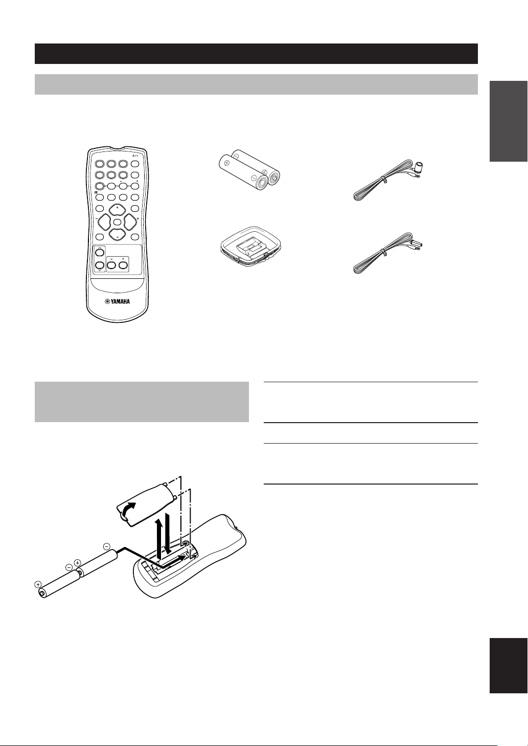
Supplied accessories
Please check that you received all of the following parts.
Remote control
DVD D-TV/CBL VCR POWER
CD MD/CD-RV-AUX 6CH IN
PRESET
TUNER
A/B/C/D/E
/DTS 6.1/5.1 NIGHT SLEEP
TEST
PROG PROG
LEVEL
VOLUME
VOLUME
STEREO
MUTE
SET MENU
Batteries (2)
(AA, R06, UM-3)
AM loop antenna
INTRODUCTION
Indoor FM antenna
(U.S.A., Canada, China, Asia and
General models)
(Europe, U.K., Australia and
Korea models)
Installing batteries in the remote control
Insert the batteries in the correct direction by aligning the
+ and – marks on the batteries with the polarity markings
(+ and –) inside the battery compartment.
1
3
4
2
1 Press the tab of the battery compartment
cover and pull it in the direction of the arrow
to open the cover.
2 Remove the cover.
3 Insert the two batteries supplied (AA, R06,
UM-3) according to the polarity markings on
the inside of the battery compartment.
4 Put the cover back into place.
■ Notes on batteries
• Change all of the batteries if you notice a decrease in
the operating range of the remote control.
• Do not use old batteries together with new ones.
• Do not use different types of batteries (such as alkaline
and manganese batteries) together. Read the packaging
carefully as these different types of batteries may have
the same shape and color.
• If the batteries have leaked, dispose of them
immediately. Avoid touching the leaked material or
letting it come into contact with clothing, etc. Clean the
battery compartment thoroughly before installing new
batteries.
English
3
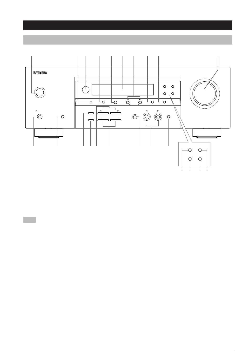
Front panel
CONTROLS AND FUNCTIONS
32 4 51 986 0
STANDBY
/ON
PRESET/TUNING
PHONES
SILENT CINEMA
SPEAKERS
A/B/OFF
q w e uyt oi
1 STANDBY/ON
Turns on this unit or sets it to the standby mode. When
you turn on this unit, you will hear a click and there will
FM/AM A/B/C/D/E
EDIT
STEREO PROGRAM INPUT
EFFECT
CONTROL
BASS/TREBLE
r
7
PRESET/TUNING
NEXT
SET MENU
INPUT MODE 6CH INPUT
5 A/B/C/D/E
Selects preset station groups A to E when the unit is in
tuner mode.
be a 4 to 5-second delay before this unit can reproduce
sound.
Selects the set menu mode when the unit is not in tuner
Note
In standby mode, this unit consumes a small amount of
power in order to receive infrared-signals from the remote
control.
2 PRESET/TUNING
Switches the function of PRESET/TUNING l / h
between selecting a preset station number and tuning (the
colon (:) turns on or off).
(EDIT)
mode.
6 Front panel display
Shows information about the operational status of the
unit.
7 PRESET/TUNING l / h
Select preset station numbers 1 to 8 when a colon (:) is
displayed in the front panel display.
Select the tuning frequency when a colon (:) is not
displayed when the unit is in tuner mode.
This button is also used to exchange the assignment of
two preset stations with each other.
3 Remote control sensor
Receives signals from the remote control.
4 FM/AM
Switches the reception band between FM and AM.
Adjust settings on the set menu when the unit is not in
tuner mode.
8 MEMORY (MAN’L/AUTO FM)
Stores a station in the memory.
9 TUNING MODE (AUTO/MAN’L MONO)
Switches the tuning mode between automatic and manual.
RDS MODE/FREQ EON
PTY SEEK
MODE START
MEMORY
TUNING MODE
MAN'L/AUTO FM
AUTO/MAN'L MONO
(U.K. and Europe models only)
(NEXT)
(SET MENU –/+)
RDS MODE/FREQ EON
PTY SEEK
MODE START
p a ds
VOLUME
4

CONTROLS AND FUNCTIONS
0 VOLUME
Controls the output level of all audio channels.
This does not affect the OUT (REC) level.
PHONES (SILENT CINEMA)
q
Allows you to enjoy DSP effects when listening with
headphones.
w SPEAKERS A/B/OFF
Selects the set of front speakers connected to the A or B
terminals. To turn off the speakers, press the button
repeatedly and select OFF.
e STEREO (EFFECT)
Switches between normal stereo and DSP effect
reproduction. When you select STEREO, the unit mixes
down all Dolby Digital and DTS signals (except the LFE
channel) as well as those 2-channel signals without effect
sounds, to the front left and right speakers.
r CONTROL
Switches between Bass (low-frequency response) control
mode and Treble (high-frequency response) control mode.
t PROGRAM l / h
Use to select sound field programs.
y BASS/TREBLE –/+
Increase or decrease low/high-frequency response when
the unit is in Bass/Treble control mode. The sound
changes 2dB each time you press one of these buttons.
Control range: –10 to +10dB.
■ U.K. and Europe models only
p RDS MODE/FREQ
Press this button when the unit is receiving an RDS
station, to cycle the display mode among PS mode, PTY
mode, RT mode, CT mode (if the station offers those
RDS data service) and/or frequency display mode in turn.
a PTY SEEK MODE
Press this button to set the unit in the PTY SEEK mode.
s PTY SEEK START
Press this button to begin searching for a station after the
desired program type has been selected in the PTY SEEK
mode.
d EON
Press this button to select a radio program type (NEWS,
INFO, AFFAIRS, SPORT) to tune in automatically.
INTRODUCTION
u INPUT MODE
Sets the priority for the types of input signals (AUTO,
DTS, ANALOG) received when one component is
connected to two types of input jacks. You cannot set
priority for an audio sources if you have selected 6CH
INPUT as the input source.
i INPUT l / h
Selects the input source you want to listen to or watch.
o 6CH INPUT
Selects the audio source connected to the 6CH INPUT
jacks. This selection takes priority over sources selected
with INPUT (or the input selector buttons on the remote
control).
English
5
CONTROLS AND FUNCTIONS
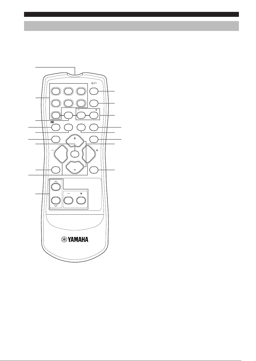
Remote control
This section describes the function of each control on the
remote control.
1
DVD D-TV/CBL VCR
POWER
q
2
CD MD/CD-R V-AUX 6CH IN
w
TUNER
A/B/C/D/E
PRESET
e
3
/DTS 6.1/5.1 NIGHT SLEEP
4
t
u
i
6
5
7
8
TEST
VOLUME
PROG PROG
MUTE
LEVEL
VOLUME
STEREO
SET MENU
9
0
1 Infrared emitter
Outputs infrared control signals. Aim this emitter at the
unit when using the remote control.
2 Input selector buttons
Select the input source and change the control area.
3 A/B/C/D/E
Selects preset station groups A to E when the unit is in
tuner mode.
4 q/DTS
Selects the built-in Dolby Digital, DTS, Dolby Pro Logic
or Pro Logic II decoder.
5 6.1/5.1
Switches on or off the Dolby Digital + Matrix 6.1 or DTS
+ Matrix 6.1 decoder.
r
6 TEST
Outputs the test tone to adjust the speaker levels.
y
7 MUTE
Mutes the sound. Press again to restore the audio output
to the previous volume level.
8 LEVEL
Selects the effect speaker channel to adjust.
9 PROGRAM –/+
Use to select sound field programs.
0 Multi control section
Use to select and adjust sound field program parameters
or SET MENU items.
q POWER
Turns the unit on, or sets it in standby mode.
w 6CH IN
Selects the audio source connected to the 6CH INPUT
jacks.
e PRESET –/+
Select preset station numbers 1 to 8.
r SLEEP
Sets the sleep timer.
6
CONTROLS AND FUNCTIONS
t NIGHT
Sets the unit in night listening mode.
y STEREO
Switches between normal stereo and DSP effect
reproduction. When you select STEREO the unit mixes
down all Dolby Digital and DTS signals (except the LFE
channel) as well as those 2-channel signals without effect
sounds, to the front left and right speakers.
u VOLUME +/–
Increases or decreases the volume level.
i SET MENU
Selects the set menu mode.
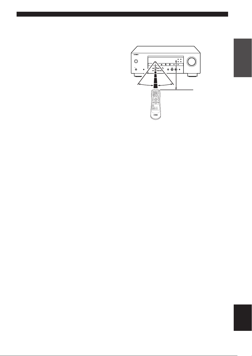
■ Using the remote control
The remote control transmits a directional infrared beam.
Be sure to aim the remote control directly at the remote
control sensor on the main unit during operation.
VOLUME
RDS MODE/FREQ EON
PTY SEEK
STANDBY
/ON
PHONES
SPEAKERS
A/B/OFF
SILENT CINEMA
30° 30°
PRESET/TUNING
FM/AM A/B/C/D/E
EDIT
NEXT
STEREO PROGRAM INPUT
EFFECT
CONTROL
BASS/TREBLE
MODE START
PRESET/TUNING
MEMORY
TUNING MODE
SET MENU
MAN'L/AUTO FM
AUTO/MAN'L MONO
INPUT MODE 6CH INPUT
Approximately 6 m (20 feet)
■ Handling the remote control
• Do not spill water or other liquids on the remote
control.
• Do not drop the remote control.
• Do not leave or store the remote control in the
following types of conditions:
– high humidity such as near a bath
– high temperature such as near a heater or stove
– extremely low temperature
– dusty places
INTRODUCTION
7
English

CONTROLS AND FUNCTIONS
Front panel display
13
MATRIX
DIGITAL
PL
PCM
SILENT CINEMA
VIRTUAL
PL
~~~~~~~~~~~~~~
SP
A B
NIGHT
V-AUXVCR
SLEEP
45
DTV/CBL
HiFi
DVD
DSP
90qw y urt ieop
62
MD/CD-R
HOLD AUTOPTY
TUNER CD
STEREO
EON
MEMORY
TUNED
CTRTPTYPS
ft
dB
7
MUTE
LFE
VOLUME
dB
L C R
SL
SB SR
a
8
s
(U.K. and Europe models only)
1 Decoder indicators
When any of this unit’s decoders function, the respective
indicator lights up.
2 SILENT CINEMA indicator
Lights up when headphones are connected and a sound
field program is selected (see page 26).
3 Headphones indicator
Lights up when headphones are connected to the
headphone jack.
4 Input source indicator
Highlights the current input source with a cursor.
5 Sound field indicator
Light to indicate the active DSP sound fields.
Presence DSP sound field
Listening position
Left surround
DSP sound field
Surround back DSP sound field
Right surround
DSP sound field
6 AUTO indicator
Shows that this unit is in the automatic tuning mode.
7 MUTE indicator
Flashes while the MUTE function is on.
8 VOLUME level indicator
Indicates the volume level.
9 PCM indicator
Lights up when this unit is reproducing PCM (pulse code
modulation) digital audio signals.
0 VIRTUAL indicator
Lights up when using Virtual CINEMA DSP.
q Multi-information display
Shows the current sound field program name and other
information when adjusting or changing settings.
w SP A B indicator
Lights up to indicate which set of front speakers is
selected. Both indicators light up when both sets of
speakers are selected.
e NIGHT indicator
Lights up when the unit is set to night listening mode.
r SLEEP indicator
Lights up while the sleep timer is on.
t HiFi DSP indicator
Lights up when you select a HiFi DSP sound field
program.
y CINEMA DSP indicator
Lights up when you select a CINEMA DSP sound field
program.
u TUNED indicator
Lights up when this unit is tuned to a radio station.
i STEREO indicator
Lights up when the unit is receiving a strong signal from
a FM stereo broadcast while the “AUTO” indicator is lit.
o MEMORY indicator
Flashes to show a station can be stored.
p LFE indicator
Lights up when the input signal contains an LFE signal.
a Input channel indicator
The indicators for the appropriate sound channels light up
when a digital signal from a source is played back.
s RDS indicator (U.K. and Europe models only)
The name(s) of the RDS data offered by the currently
received RDS station light(s) up.
EON lights up when an RDS station that offers the EON
data service is being received.
PTY HOLD lights up while searching for stations in the
PTY SEEK mode.
8
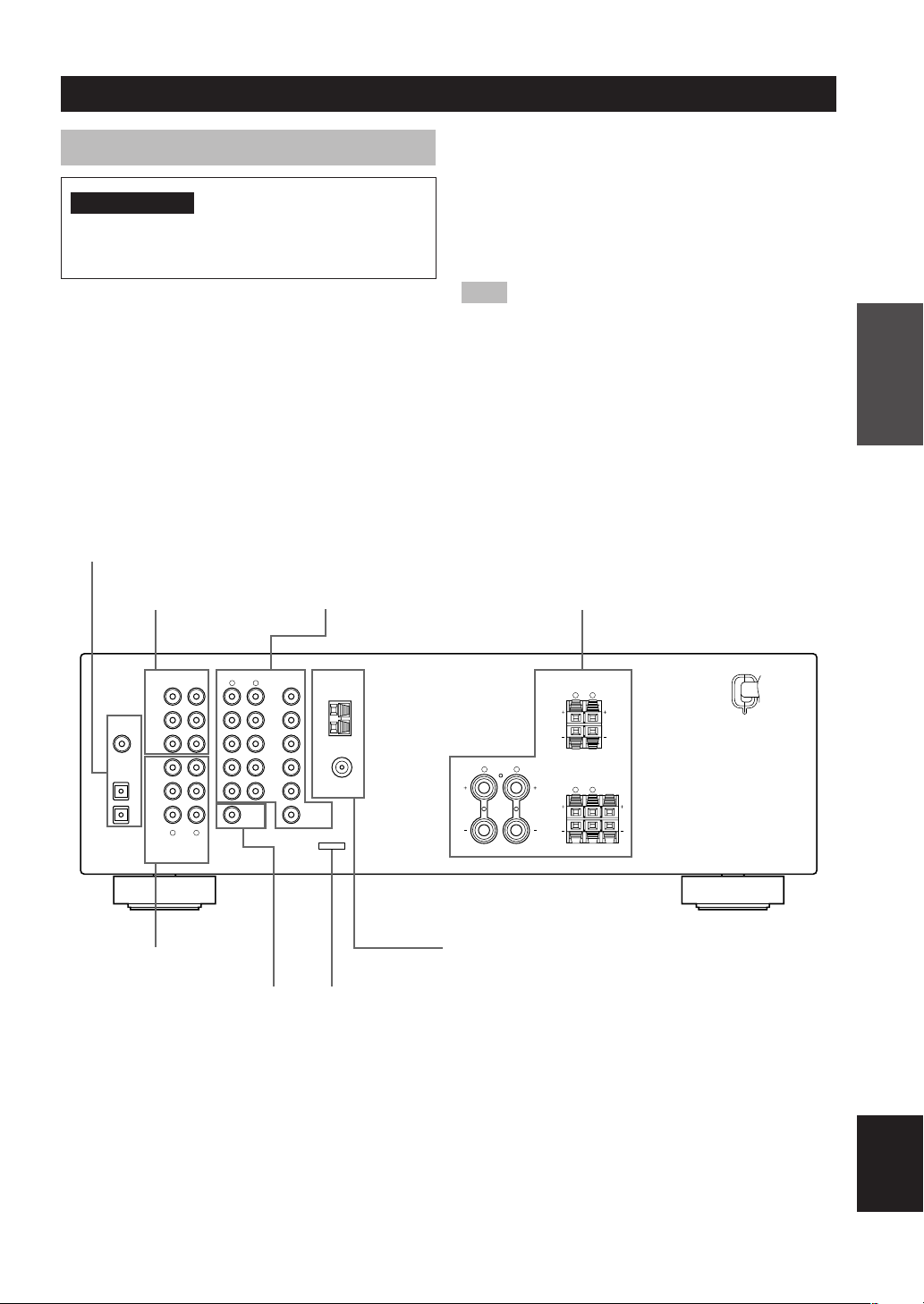
CONNECTIONS
Before connecting components
CAUTION
Do not connect this unit or other components to the
mains power until all connections between the
components have been completed.
• Be sure to connect the left channel (L), right channel
(R), “+” (red) and “–” (black) properly. Some
components require different connection methods and
have different jack names. Refer to the operation
instructions for each component you wish to connect to
this unit.
• After you have completed all connections, check them
again to make sure they are correct.
• The jack names correspond to the names on the input
selector.
DIGITAL INPUT jacks
(pages 9 – 11)
6CH INPUT jacks
(page 13)
Video component jacks
(page 10)
■ Connecting to digital jacks
This unit has digital jacks for direct transmission of
digital signals through either a coaxial or fiber optic
cable. You can use the digital jacks to input PCM, Dolby
Digital and DTS bitstreams. Use digital connections if
you wish to enjoy the multi-channel sound track of DVD
material, etc. with DSP effects. Both digital input jacks
are acceptable for 96 kHz sampling digital signals.
Note
• The OPTICAL jack on this unit conform to the EIA standard.
If you use a fiber optic cable that does not conform to EIA
standard, this unit may not function properly.
Speaker terminals
(page 16)
PREPARATION
6CH INPUT AUDIO VIDEO TUNER SPEAKERS
FRONT
DIGITAL
SURROUND
INPUT
CD
3
COAXIAL
OPTICAL
/CBL
SUB
WOOFER
CD
DTV
2
(PLAY)
MD
DVD
1
/CD-R
OUT
(REC)
CENTER
IN
LR
AUDIO OUTPUT
Audio component jacks
(page 11)
SUBWOOFER OUTPUT
jack (page 16)
L
R
DVD
AM
ANT
DTV
/CBL
GND
SUB
WOOFER
V-AUX
75Ω UNBAL.
FM
IN
ANT
VCR
OUT
MONITOR
OUT
A
FRONT
L
R
FRONT A OR B : 6ΩMIN. /SPEAKER CENTER : 6ΩMIN. /SPEAKER
SURROUND
R
SURROUND : 6
CLASS 2 WIRING
FRONT
R
L
Ω
MIN. /SPEAKER
B
L
CENTER
Antenna input terminals
(page 12)
This jack is reserved for factory use.
Do not connect any equipment to this jack.
English
9
CONNECTIONS
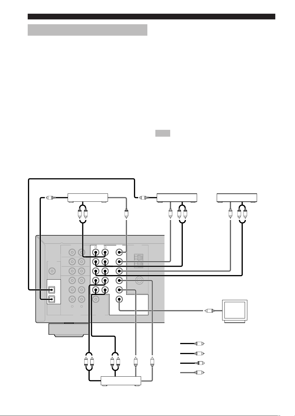
Connecting video components
■ Connecting a video monitor
Connect the video input jack on your video monitor to the
MONITOR OUT VIDEO jack.
■ Connecting a DVD player/digital TV/cable
TV
Connect the optical digital audio signal output jack on
your component to the DIGITAL INPUT jack and
connect the video signal output jack on the component to
the VIDEO jack on this unit.
y
• Use the AUDIO jacks on this unit for a video component
which does not have optical digital output jack. However,
multi-channel reproduction cannot be obtained with audio
signals input from the AUDIO jacks.
■ Connecting a digital TV/cable TV
Connect the video signal output jack on your component
to the VIDEO jack on this unit.
Connect the audio signal output jacks on the component
to the AUDIO jacks on this unit.
O
OPTICAL
OUTPUT
DVD player
AUDIO
LVR
OUTPUT
OPTICAL
OUTPUT
VIDEO
OUTPUT
O
■ Connecting another video component
Connect the video signal output jack on your component
to the VIDEO jack on this unit.
Connect the audio signal output jacks on the component
to the AUDIO jacks on this unit.
■ Connecting a recording component
Connect the audio signal input jacks on your video
component to the AUDIO OUT jacks on this unit. Then
connect the video signal input jack on the video
component to the VIDEO OUT jack on this unit for
picture recording.
Connect the audio signal output jacks on your component
to the AUDIO IN jacks on this unit. Then connect the
video signal output jack on the component to the VIDEO
IN jack on this unit to play a source from your recording
component.
Note
• Once you have connected a recording component to this unit,
keep its power turned on while using this unit. If the power is
off, this unit may distort the sound from other components.
TV/digital TV/
VIDEO
OUTPUT
cable TV
V
L R
AUDIO
OUTPUT
Another video
VIDEO
OUTPUT
component
V
L R
AUDIO
OUTPUT
10
DIGITAL
INPUT
CD
COAXIAL
OPTICAL
DTV
/CBL
DVD
6CH INPUT TUNER
FRONT
SURROUND
3
SUB
WOOFER
CD
2
IN
(PLAY)
MD
1
/CD-R
OUT
(REC)
AUDIO OUTPUT
AUDIO
OUTPUT
CENTER
LR
LR
AUDIO VIDEO
R
SUB
WOOFER
AUDIO
INPUT
L
DVD
DTV
/CBL
V-AUX
IN
VCR
OUT
LR
VCR
AM
ANT
GND
FM
ANT
MONITOR
OUT
75Ω UNBAL.
VIDEO
V V
INPUT
VIDEO
OUTPUT
Video monitor
V
VIDEO
INPUT
L
indicates left analog cables
R
indicates right analog cables
O
indicates optical cables
V
indicates video cables
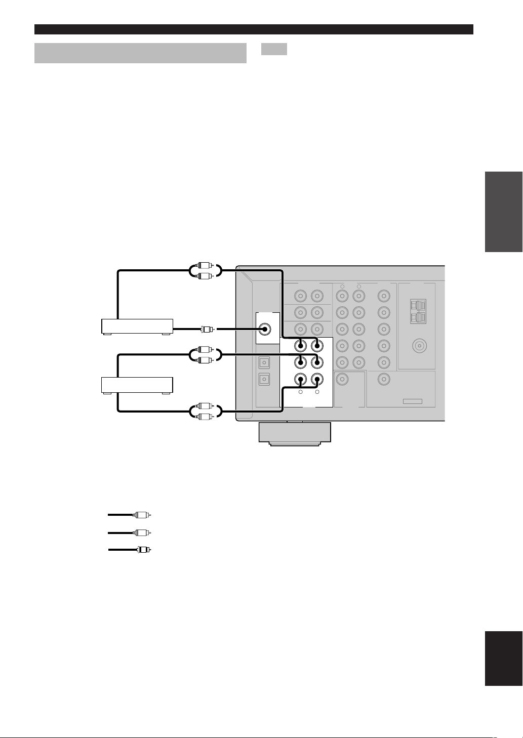
CONNECTIONS
Connecting audio components
■ Connecting a CD player
Connect the coaxial digital output jack on your CD player
to the DIGITAL INPUT CD jack on this unit.
y
• Use the AUDIO jacks on this unit to connect to a CD player
that does not have a COAXIAL DIGITAL OUTPUT jack, or
to record from CD players.
■ Connecting a CD recorder or MD
recorder
Connect the input jacks on your CD recorder or MD
recorder to the MD/CD-R OUT (REC) jacks.
Connect the output jacks on your CD recorder or MD
recorder to the MD/CD-R IN (PLAY) jacks to play a
source from your recording component.
L
COAXIAL
OUTPUT
R
C
L
R
L
R
CD player
CD recorder or
MD recorder
AUDIO
OUTPUT
AUDIO
OUTPUT
AUDIO
INPUT
Note
• Once you have connected a recording component to this unit,
keep its power turned on while using this unit. If the power is
off, this unit may distort the sound from other components.
DIGITAL
CD
COAXIAL
OPTICAL
DTV
/CBL
DVD
INPUT
6CH INPUT AUDIO VIDEO TUNER
FRONT
SURROUND
3
SUB
WOOFER
CD
2
IN
(PLAY)
MD
1
/CD-R
OUT
(REC)
CENTER
LR
AUDIO
R
OUTPUT
SUB
WOOFER
L
DVD
DTV
/CBL
V-AUX
VCR
OUT
IN
AM
ANT
GND
FM
ANT
MONITOR
OUT
75Ω UNBAL.
PREPARATION
L
indicates left analog cables
R
indicates right analog cables
C
indicates coaxial cables
English
11
CONNECTIONS
100 kHz/10kHz
50 kHz/ 9kHz
FM/AM
FREQUENCY STEP
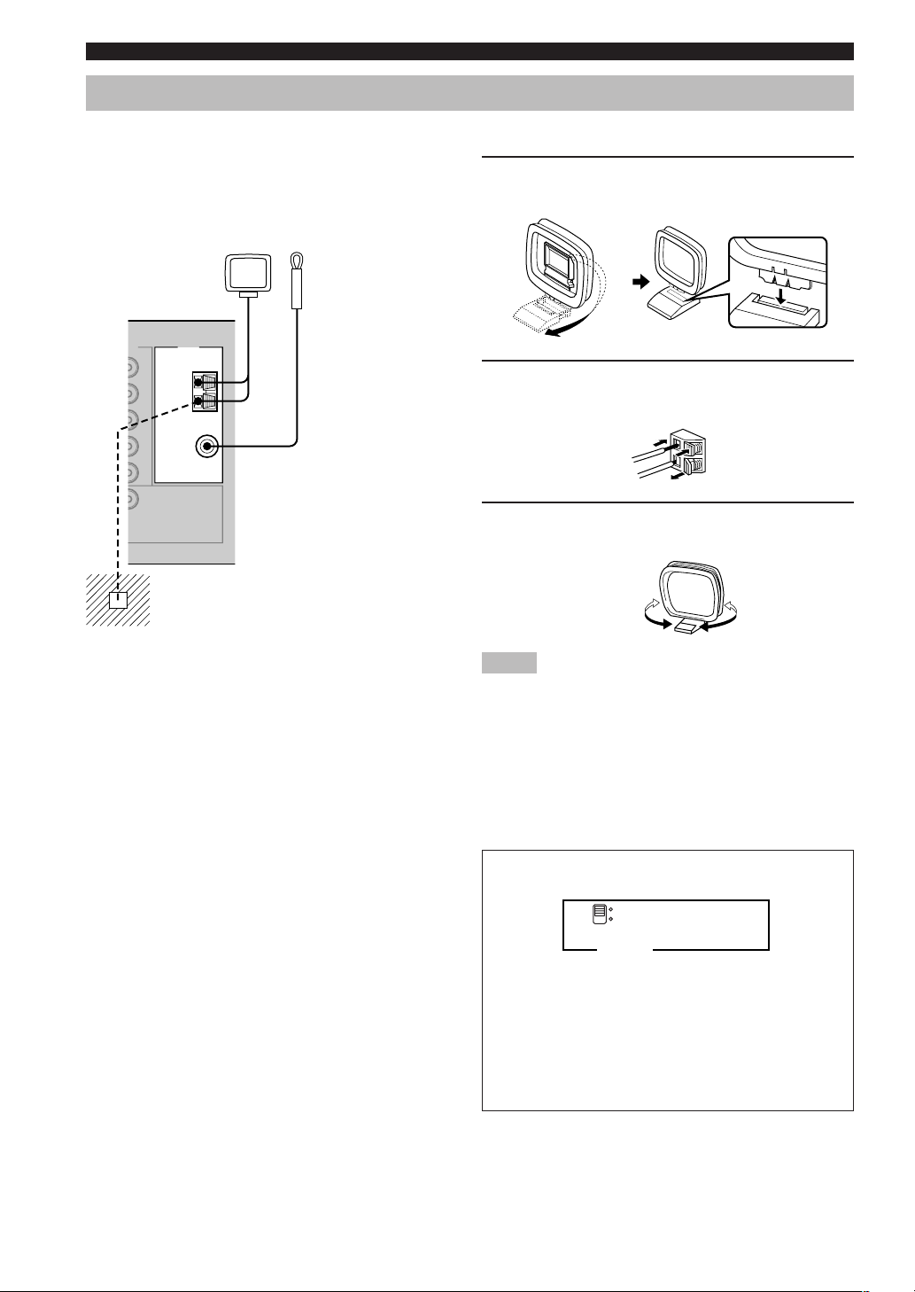
Connecting the antennas
Both AM and FM indoor antennas are included with this
unit. In general, these antennas should provide sufficient
signal strength.
Connect each antenna correctly to the designated
terminals.
AM loop antenna
(included)
EO TUNER
AM
ANT
GND
75Ω UNBAL.
FM
ANT
MONITOR
OUT
Ground (GND terminal)
For maximum safety and minimum
interference, connect the antenna GND
terminal to a good earth ground. A good
earth ground is a metal stake driven into
moist earth.
Indoor FM
antenna
(included)
■ Connecting the AM loop antenna
1 Set up the AM loop antenna, then connect it
to the terminals on this unit.
2 Press and hold the tab to insert the AM loop
antenna lead wires into the AM ANT and
GND terminals.
3 Orient the AM loop antenna for the best
reception.
Notes
• The AM loop antenna should be placed away from this unit.
• The AM loop antenna should always be connected, even if an
outdoor AM antenna is connected to this unit.
• A properly installed outdoor antenna provides clearer
reception than an indoor one. If you experience poor reception
quality, an outdoor antenna may improve the quality. Consult
the nearest authorized YAMAHA dealer or service center
about the outdoor antennas.
FREQUENCY STEP switch
(Asia and General models only)
Because the interstation frequency spacing differs in
different areas, set the FREQUENCY STEP switch
(locating on the rear panel) according to the frequency
spacing in your area.
• North, Central and South America: 100 kHz/10 kHz
• Other areas: 50 kHz/9 kHz
Before setting this switch, disconnect this unit’s AC
power cord from the wall outlet.
12
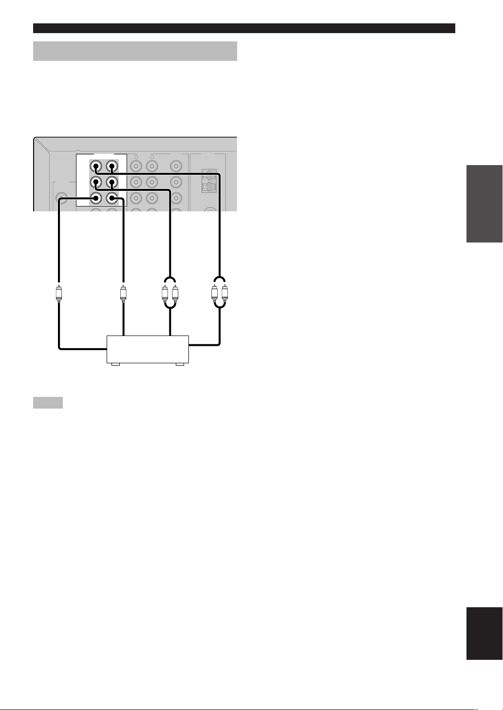
Connecting an external decoder
This unit is equipped with 6 additional input jacks
(FRONT left and right, CENTER, SURROUND left and
right and SUBWOOFER) for discrete multi-channel input
from a component equipped with a multi-channel decoder
and 6 channel output jacks such as a DVD/Super Audio
CD player.
CONNECTIONS
6CH INPUT
FRONT
DIGITAL
SURROUND
INPUT
CD
3
SUB
WOOFER
SUBWOOFER FRONT
SUBWOOFER
AUDIO VIDEO TUNER
L
R
DVD
DTV
CENTER
CENTER SURROUND
CENTER SURROUND
/CBL
V-AUX
L R
AM
ANT
GND
75Ω UNBAL.
LR
DVD/Super Audio CD player
Notes
• When you select 6CH INPUT as the input source, this unit
automatically turns off the digital sound field processor, and
you cannot select sound field programs.
• When headphones are used, only front L/R channels are
output.
PREPARATION
13
English
CONNECTIONS
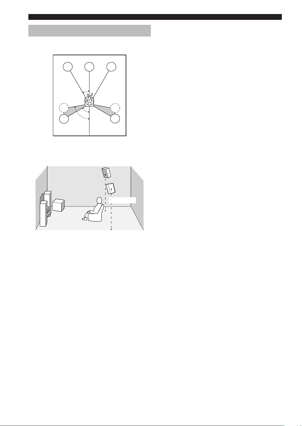
Connecting the speakers
■ Speaker placement
FL
SL
SL
C
30˚
60˚
80˚
The speaker layout above shows the standard ITU-R
speaker setting. You can use it to enjoy CINEMA DSP,
multi-channel audio sources.
FR
SR
SR
Subwoofer
The use of a subwoofer, such as the YAMAHA Active
Servo Processing Subwoofer System, is effective not only
for reinforcing bass frequencies from any or all channels,
but also for high fidelity reproduction of the LFE (low frequency effect) channel included in Dolby Digital and
DTS software. The position of the subwoofer is not so
critical, because low bass sounds are not highly
directional. But it is better to place the subwoofer near the
front speakers. Turn it slightly toward the center of the
room to reduce wall reflections.
1.8 m (6 ft)
Front speakers (FR and FL)
The front speakers are used for the main source sound
plus effect sounds. Place these speakers an equal distance
from the ideal listening position. The distance of each
speaker from each side of the video monitor should be the
same.
Center speaker (C)
The center speaker is for the center channel sounds
(dialog, vocals, etc.). If for some reason it is not practical
to use a center speaker, you can do without it.
Best results, however, are obtained with the full system.
Align the front face of the center speaker with the front
face of your video monitor. Place the speaker centrally
between the front speakers and as close to the monitor as
possible, such as directly over or under it.
Surround speakers (SR and SL)
The surround speakers are used for effect and surround
sounds. Place these speakers behind your listening
position, facing slightly inwards, about 1.8 m (6 ft) above
the floor.
14
CONNECTIONS
■ Speaker connections
Be sure to connect the left channel (L), right channel (R), “+” (red) and “–” (black) properly. If the connections are
faulty, no sound will be heard from the speakers, and if the polarity of the speaker connections is incorrect, the sound
will be unnatural and lack bass.
CAUTION
• Use speakers with the specified impedance shown on the rear panel of this unit.
• Before connecting the speakers, make sure that the power of this unit is off.
• Do not let the bare speaker wires touch each other or do not let them touch any metal part of this unit. This could
damage this unit and/or speakers.
• Use magnetically shielded speakers. If this type of speakers still creates the interference with the monitor, place
the speakers away from the monitor.
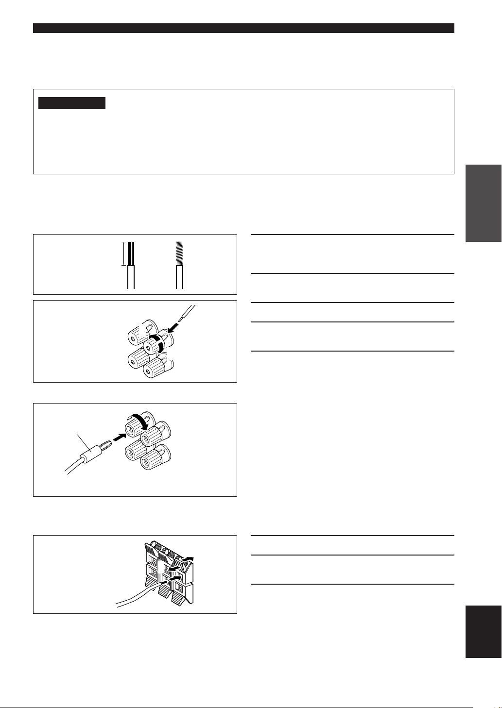
Connecting to the FRONT A SPEAKERS terminals
A speaker cord is actually a pair of insulated cables running side by side. One cable is colored or shaped differently,
perhaps with a stripe, groove or ridges. Connect the striped (grooved, etc.) cable to the “+” (red) terminals on this unit
and your speaker. Connect the plain cable to the “–” (black) terminals.
1 Remove approximately 10 mm (3/8") of
10 mm (3/8”)
insulation from the end of each of the
speaker cables.
PREPARATION
12
Red: positive (+)
Black: negative (–)
3
4
5
Banana plug
(With the exception of U.K., Europe and Asia models)
Connecting to the FRONT B, CENTER and SURROUND SPEAKERS terminals
2 Twist the exposed wires of the cable
together to prevent short circuits.
3 Unscrew the knob.
4 Insert one bare wire into the hole in the side
of each terminal.
5 Tighten the knob to secure the wire.
Banana plug connections
(With the exception of U.K., Europe and Asia models)
First, tighten the knob and then insert the banana plug
connector into the end of the corresponding terminal.
1 Press and open the tab.
Red: positive (+)
Black: negative (–)
3
1
2 Insert one bare wire into the hole of each
terminal.
3 Release the tab to secure the wire.
2
English
15
CONNECTIONS
1
2
4
3
6
5
DIGITAL
CD
COAXIAL
OPTICAL
DTV
/CBL
DVD
INPUT
Front A speaker
Right Left Left
21
6CH INPUT AUDIO VIDEO TUNER SPEAKERS
FRONT
SURROUND
3
SUB
WOOFER
CD
2
IN
(PLAY)
MD
1
/CD-R
OUT
(REC)
LR
AUDIO OUTPUT
CENTER
L
R
DVD
AM
ANT
DTV
/CBL
GND
SUB
WOOFER
V-AUX
75Ω UNBAL.
FM
IN
ANT
VCR
OUT
MONITOR
OUT
A
FRONT
R
FRONT A OR B : 6ΩMIN. /SPEAKER CENTER : 6ΩMIN. /SPEAKER
4
Subwoofer
system
Surround speaker
Right
SURROUND
L
R
SURROUND : 6ΩMIN. /SPEAKER
CLASS 2 WIRING
L
R
FRONT
B
CENTER
L
Right Left
Front B speaker
65
3
Center
speaker
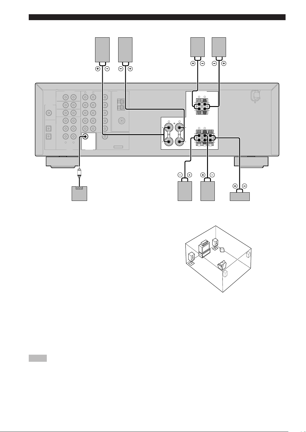
FRONT SPEAKERS terminals
You can connect up to two speaker systems to these
terminals. When using only one speaker system, connect
it to either of the FRONT A or the FRONT B terminals.
SURROUND SPEAKERS terminals
A surround speaker system can be connected to these
terminals.
CENTER SPEAKER terminals
A center speaker can be connected to these terminals.
The diagram shows the speaker layout in the listening
room.
SUBWOOFER jack
When using a subwoofer with built-in amplifier, including the YAMAHA Active Servo Processing Subwoofer System,
connect the input jack of the subwoofer system to this jack. This unit will direct low bass signals distributed from the
front, center and/or surround channels to this jack in accordance with your SPEAKER SET selections. The LFE (lowfrequency effect) signals generated when Dolby Digital or DTS is decoded are also directed to this jack in accordance
with your SPEAKER SET selections.
Notes
• The cut-off frequency of the SUBWOOFER jack is 90 Hz.
• If you do not use a subwoofer, allocate the signals to the front left and right speakers by changing the setting of “SOUND 1
SPEAKER SET” item “1D BASS” on the set menu to FRONT.
• Use the control on the subwoofer to adjust its volume level. You can also adjust the volume level by using this unit’s remote control
(see “SETTING THE SPEAKER LEVELS” on page 45).
16
CONNECTIONS
U
N
N
1
Connecting the power supply cords
VOLTAGE SELECTOR
VOLTAGE
SELECTOR
REAR
)
RROUND
L
./SPEAKER
./SPEAKER
(Asia and General models)
■ Connecting the AC power cord
Plug the power cord into an AC wall outlet.
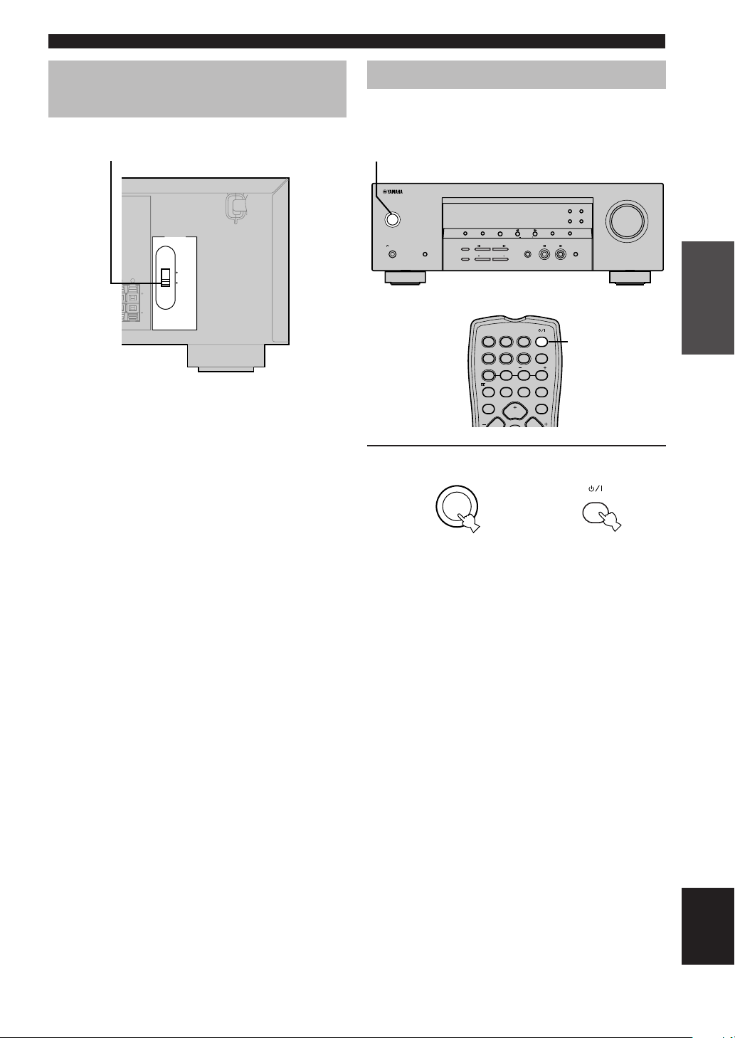
■ VOLTAGE SELECTOR
(Asia and General models only)
The VOLTAGE SELECTOR on the rear panel of this unit
must be set for your local main voltage BEFORE
plugging into the AC main supply. Voltages are 110 V 120 V/220 V - 240 V AC, 50/60 Hz.
110V-120V
220V-240V
Turning on the power
When all connections are complete, turn on the power of
this unit.
1
RDS MODE/FREQ EON
PTY SEEK
STEREO
MAN'L/AUTO FM
MODE START
MEMORY
TUNING MODE
AUTO/MAN'L MONO
STANDBY
SILENT CINEMA
/ON
PHONES
PRESET/TUNING
SPEAKERS
A/B/OFF
FM/AM A/B/C/D/E
PRESET/TUNING
NEXT
EDIT
STEREO PROGRAM INPUT
EFFECT
CONTROL
PROG PROG
SET MENU
INPUT MODE 6CH INPUT
BASS/TREBLE
DVD D-TV/CBL VCR POWER
CD MD/CD-R V-AUX 6CH IN
A/B/C/D/E
TUNER
PRESET
/DTS 6.1/5.1 NIGHT SLEEP
TEST
VOLUME
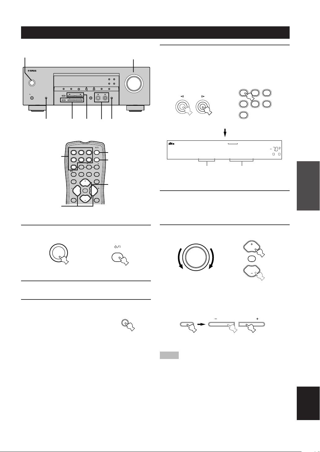
1 Press STANDBY/ON (POWER on the remote
control) to turn on the power of this unit.
STANDBY
/ON
Front panel
or
Remote control
VOLUME
POWER
PREPARATION
The level of the volume, and then the current sound
field program name appear on the front panel
display.
English
17
BASIC SYSTEM SETTINGS
The “BASIC” menu allows you to set some of the basic “SOUND” menu parameters with a minimum of effort. If you
wish to configure the unit more precisely to suit your listening environment, use the more detailed parameters from the
“SOUND” menu instead of those under the “BASIC” menu (See page 40). Altering any parameters in the BASIC menu
will reset all parameters in the “SOUND” menu.
Using the basic menu
Use the remote control to make adjustments.
• Press SPEAKERS A/B/OFF on the front panel to select
the front speakers you want to use.
• Make sure you disconnect headphones from this unit.
TEST
PROG PROG
LEVEL
3,6
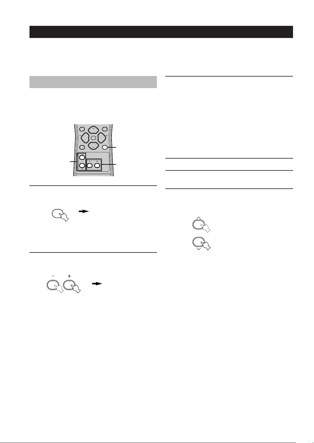
1 Press SET MENU.
“BASIC MENU” appears on the front panel display.
SET MENU
If the front panel display changes to show anything
other than “BASIC MENU”, press SET MENU until
it displays “BASIC MENU”.
2 Press – / + to enter into the BASIC menu.
“1 SETUP” appears on the front panel display.
STEREO
VOLUME
MUTE
SET MENU
VOLUME
1
2,4
BASIC MENU
1 SETUP
3 Press u / d to change the display to the
setting you want to alter.
1 SETUP
Changes the speaker and amplifier settings to suit the
size of the room you are using. Refer to “Setting the
unit to match your speaker system” on page 20 for
more information.
2 SP LEVEL
Adjusts the output levels of the speakers.
Refer to “SP LEVEL” on page 20 for more
information.
4 Press – / + to enter the desired setting mode.
5 Change the unit settings to suit your
listening environment.
6 Press u / d to exit from the set menu.
The front panel display changes in the following
order:
Exit
↑
BASIC
↓↑
SOUND
↓↑
INPUT
↓↑
OPTION
↓
Exit
18
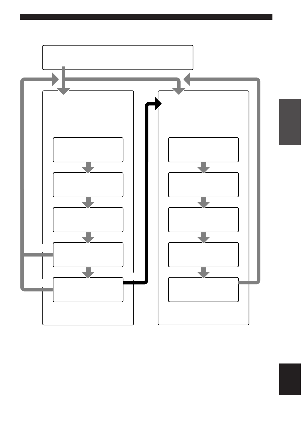
■ Basic menu operation sequence
SET MENU
BASIC SOUND INPUT OPTION
BASIC SYSTEM SETTINGS
1 SETUP
Press – / + to alter the settings for each
parameter. Use d to move to the next
setting.
1 ROOM
Choose from S/M/L.
2 SUBWOOFER
Choose either of YES/NONE.
3 SPEAKERS
Choose from 2/3/4/5 spk.
CANCEL
4 SET/CANCEL
Choose either of SET/CANCEL.
2 SP LEVEL
Press – / + to adjust the balance
between each speaker and the front left
speaker. Use d to move to the next
setting.
1 L-R
Adjust the balance between the front
left and right speakers.
2 C
Adjust the balance between the front
left and center speakers.
3 SL
Adjust the balance between the front
left and surround left speakers.
4 SR
Adjust the balance between the surround
left and surround right speakers.
PREPARATION
SET
YES
5 CHECK OK:
Choose either of YES/NO.
• After altering the “1 SETUP” parameters, readjust the output levels of the speakers at “2 SP LEVEL”.
• See pages 39 – 44 for a detailed explanation of the “SOUND”, “INPUT” and “OPTION” menus.
NO
5 SWFR
Adjust the balance between the front
left speaker and the subwoofer.
English
19
BASIC SYSTEM SETTINGS
Setting the unit to match your speaker system
Follow the instructions below to set the amplifier output
to match the size of your room and speakers. Press u / d
to cycle through parameters 1 through 4, and – / + to alter
the parameter setting.
Factory default settings are highlighted.
1 ROOM
Settings: S, M, L
Select the size of the room you have installed your
speakers in. Roughly speaking, the room sizes are
defined as follows:
[U.S.A. and Canada models]
S: 16 x 13 ft, 200 ft
M: 20 x 16 ft, 300 ft2 (6.3 x 5.0 m, 30 m2 )
L: 26 x 19 ft, 450 ft
[Other models]
S: 3.6 x 2.8 m, 10 m
M: 4.8 x 4.0 m, 20 m
L: 6.3 x 5.0 m, 30 m
2 SUBWOOFER
Settings: YES, NONE
Select YES if you have a subwoofer in your system,
or NONE if you do not.
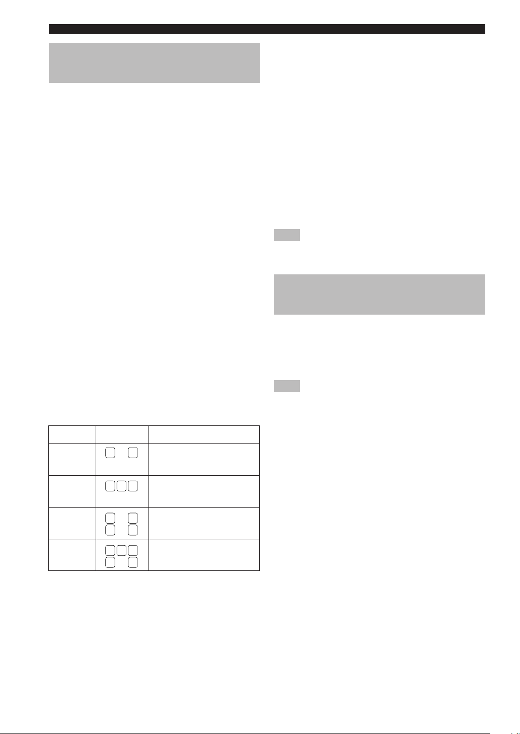
3 SPEAKERS
Settings: 2, 3, 4, 5 (spk)
Select the number of speakers connected in your
speaker configuration. This number does not include
your subwoofer.
Setting
2spk
3spk
4spk
5spk
Display
L R
L C R
L R
SL SR
L C R
SL SR
2
(4.8 x 4.0 m, 20 m2)
2
(7.9 x 5.8 m, 45 m2 )
2
2
2
Speaker
Front L/R
Front L/R,
Center
Front L/R,
Surround L/R
Front L/R, Center,
Surround L/R
4 SET or CANCEL
Select SET to confirm the changes you made. Select
CANCEL to exit SETUP MENU without altering any
of the unit settings. The unit will output a test tone to
the speakers (see 5).
5 Use the test tone to check the speaker levels.
When you select SET in 4, the display changes to
“CHECK : Test Tone” for a few seconds, and the unit
outputs a test tone to each of the speakers in turn
twice. When the test tone begins, the display changes
to “CHECK OK?--YES”.
If the test tone is output at the same volume from all
of the speakers, select “CHECK OK: YES”. Press d
to exit from the SETUP menu.
If the volume of the test tone varies between speakers,
press – / + to change the display to “NO”.
Note
• The indicator of the speaker currently outputting the test tone
flashes on the front panel display.
2 SP LEVEL
(Setting speaker output levels)
Use this menu to compare and adjust the test tone output
from each speaker to the output from the front left (or
surround left) speaker so that the volume level for all
speakers is identical. Press u / d to select a speaker,
then adjust the balance using – / +.
Note
• The unit outputs the test tone from the selected speaker and
the front left (or surround left) speaker in turn. The indicator
of the speaker currently outputting the test tone flashes on the
front panel display.
L-R
Adjust the balance between the front left and right
speakers.
C
Adjust the balance between the front left and center
speakers.
SL
Adjust the balance between the front left and
surround left speakers.
SR
Adjust the balance between the surround left and
surround right speakers.
20
SWFR
Adjust the balance between the front left speaker and
the subwoofer.
PLAYBACK
INPUT
1
6
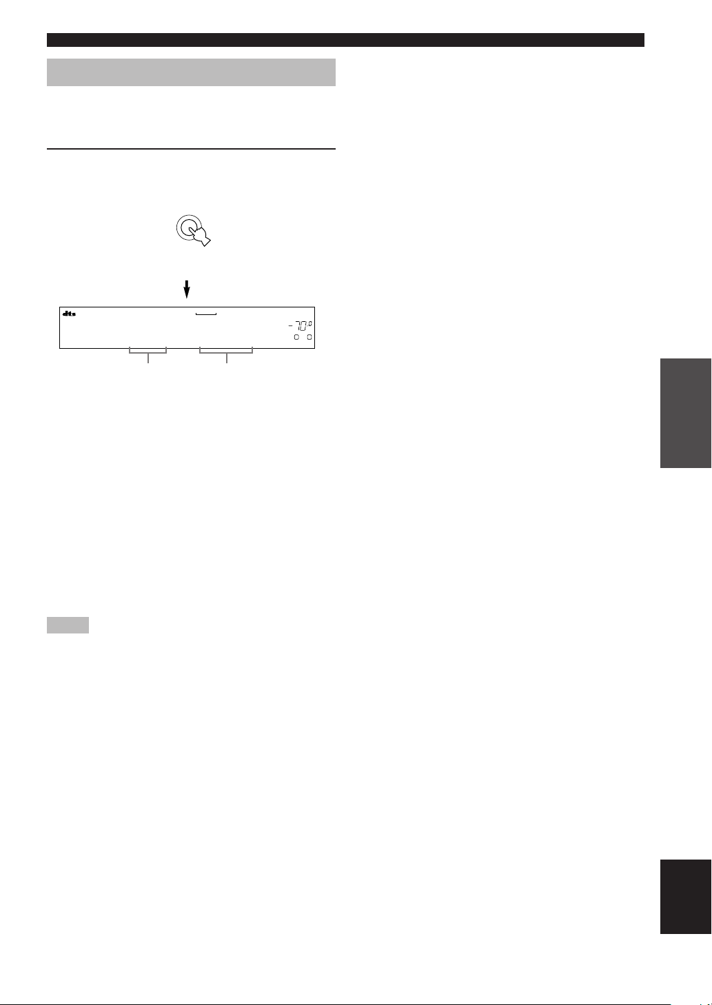
4 Press INPUT l / h repeatedly (one of the
input selector buttons on the remote control)
to select the input you desire.
The selected input source name and input mode
appear on the front panel display for a few seconds.
DVD D-TV/CBL VCR
CD MD/CD-R V-AUX
or
TUNER
Front panel
V-AUXVCR
DVD AUTO
Selected input source
DTV/CBL
Remote control
DVD
MD/CD-R
Input mode
TUNER CD
VOLUME
L R
dB
5 Start playback or select a broadcast station
on the source component.
Refer to the operation instructions for the
OPERATION
BASIC
STANDBY
PHONES
SILENT CINEMA
RDS MODE/FREQ EON
PTY SEEK
STEREO
SET MENU
MEMORY
MAN'L/AUTO FM
4
MODE START
TUNING MODE
AUTO/MAN'L MONO
1
7
6
/ON
PRESET/TUNING
SPEAKERS
A/B/OFF
4
FM/AM A/B/C/D/E
PRESET/TUNING
NEXT
EDIT
STEREO PROGRAM INPUT
EFFECT
CONTROL
6
TUNER
PROG PROG
SET MENU
INPUT MODE 6CH INPUT
BASS/TREBLE
73 7
DVD D-TV/CBL VCR POWER
CD MD/CD-R V-AUX 6CH IN
PRESET
A/B/C/D/E
/DT S 6.1/ 5.1 N IGHT SLEEP
TEST
VOLUME
MUTE
LEVEL
VOLUME
VOLUME
7
component.
1 Press STANDBY/ON (POWER on the remote
control) to turn on the power.
STANDBY
/ON
Front panel
or
POWER
Remote control
2 Turn on the video monitor connected to this
unit.
3 Press SPEAKERS A/B/
OFF on the front panel to
select the front speakers
you want to use.
SPEAKERS
A/B/OFF
6 Adjust the volume to the desired level.
VOLUME
or
If desired, use CONTROL and BASS/TREBLE –/+.
These controls only effect the sound from the front
speakers.
CONTROL
BASS/TREBLE
Front panel
Notes
• If you increase or decrease the high-frequency or the lowfrequency sound to an extreme level, the tonal quality from the
center and surround speakers may not match that of the front
left and right speakers.
• If you have connected a recording component to the VCR
OUT, or MD/CD-R OUT jacks, and you notice distortion or
low volume during playback from other components, try
turning on the recording component.
VOLUME
MUTE
VOLUME
Remote controlFront panel
English
21

PLAYBACK
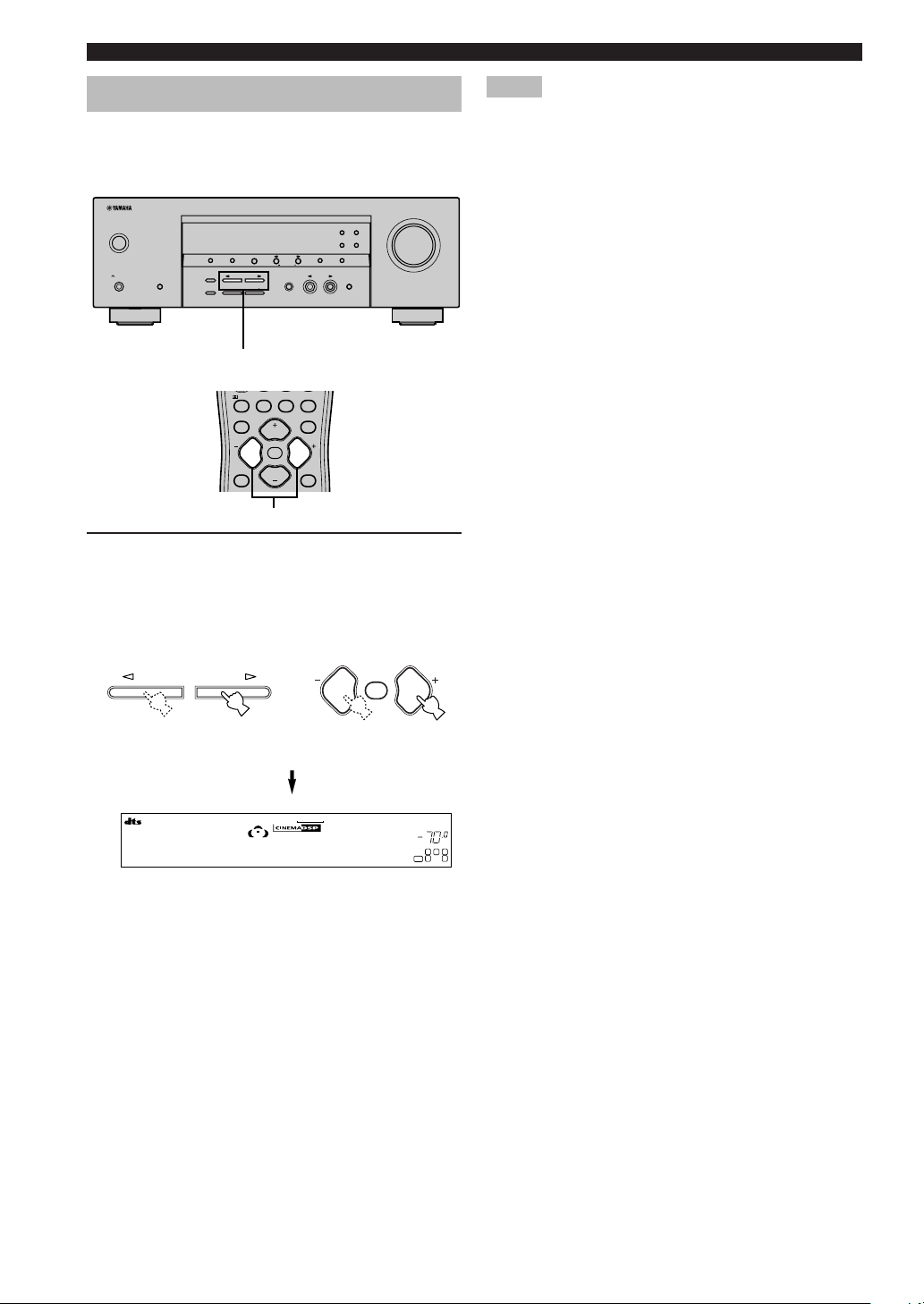
7 Select a sound field program if desired.
Use PROGRAM l / h (PROG –/+ on the remote
control) to select a sound field program. See pages
27 – 30 for details about sound field programs.
PROGRAM
Front panel Remote control
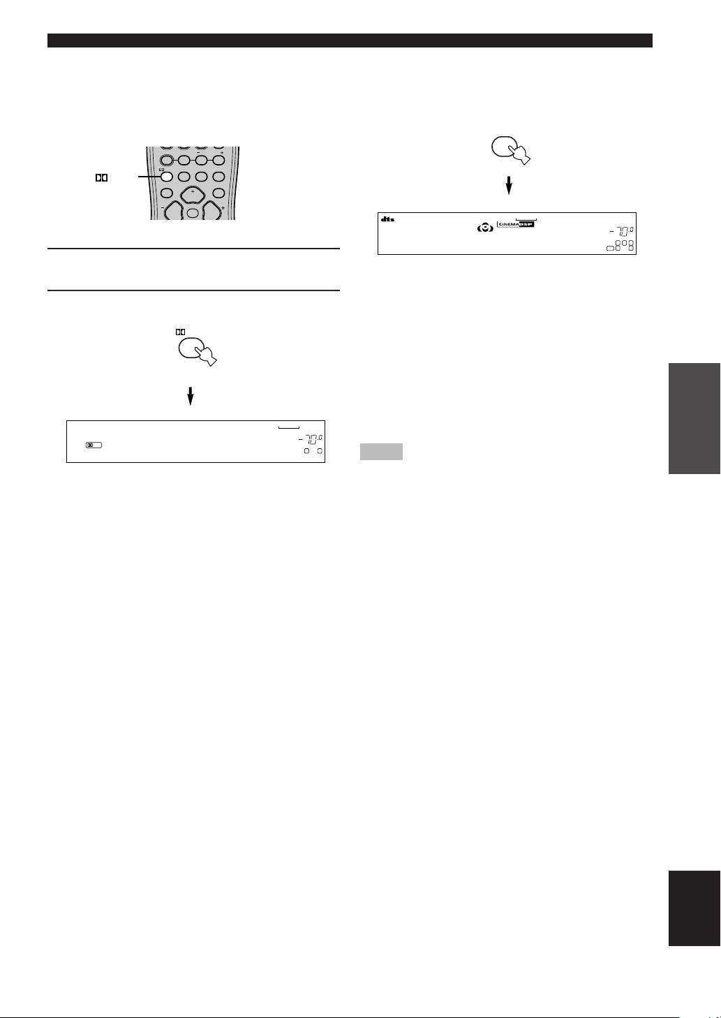
■ Selecting the 6CH INPUT
Press 6CH INPUT until “6CH INPUT” appears on the
front panel display.
6CH INPUT
or
Front panel
Note
• If “6CH INPUT” is shown on the front panel display, no other
source can be played. To select another input source, first
press 6CH INPUT so that “6CH INPUT” disappears from the
front panel display.
PROG PROG
or
MUTE
6CH IN
Remote control
■ Playing video sources in the background
You can combine a video image from a video source with
a sound from an audio source. For example, you can
enjoy listening to classical music while having beautiful
scenery from the video source on the video monitor.
Use the input selector buttons to select a video source,
then select an audio source.
DVD D-TV/CBL VCR
CD MD/CD-R V-AUX
TUNER
■ To mute the sound
Press MUTE on the
remote control.
“MUTE” blinks on the front
panel display.
To resume audio output, press
MUTE again.
y
• You can also cancel mute by pressing VOLUME +/–, etc.
• You can adjust the muting level (see page 44).
MUTE
■ Night listening mode
This mode reproduces dialogue clearly while reducing the
volume of loud sound effects for easier listening at low
volumes or at night.
Press NIGHT on the
NIGHT
remote control.
The NIGHT indicator in the
front panel display lights up.
Press NIGHT once more to
return to normal reproduction.
y
• You can use night listening mode with any of the sound field
programs.
• Night listening mode may vary in effectiveness depending on
the input source and surround sound settings you use.
22
■ When you have finished using this unit
Press STANDBY/ON (POWER on the remote
control) to set this unit in standby mode.
STANDBY
/ON
Front panel Remote control
or
POWER
Input modes and indications
This unit is equipped with 2 types of input jacks. Do the
following to select the type of input signals you want to
use.
Press INPUT MODE repeatedly until the
desired input mode is shown on the front
panel display.
INPUT MODE
Front panel
V-AUXVCR
DTV/CBL
DVD
MD/CD-R
TUNER CD
DVD AUTO
VOLUME
L R
dB
PLAYBACK
Selected input source
AUTO
Automatically selects input signals in the
Input mode
following order:
1) Digital signals*
2) Analog signals
DTS
Selects only digital signals encoded in DTS.
If no DTS signals are input, no sound is
output.
ANALOG
Selects only analog signals. If no analog
signals are input, no sound is output.
* If this unit detects a Dolby Digital or DTS signal, the decoder
automatically switches to the appropriate sound field program.
y
You can adjust the default input mode this unit selects when
the power is turned on (see page 43).
Notes
•
When you play DTS encoded CD/LDs with the input mode set to
AUTO :
– This unit automatically switches to the DTS decoding
mode. The unit remains in DTS mode (and the “t”
indicator may flash) for up to 30 second after playback of
the DTS source is complete. To manually release the DTS
mode, press INPUT MODE to reselect AUTO.
– The DTS decoding mode may be released if search or skip
operations are performed for more than 30 seconds. To
prevent this, press INPUT MODE to select DTS.
• If the digital output data of the player has been processed in
any way, you may not be able to perform DTS decoding even
if you make a digital connection between this unit and the
player.
OPERATION
BASIC
23
English
PLAYBACK
Selecting a sound field program
You can enhance your listening experience by selecting
sound field programs. For details about each program, see
pages 27 – 30.
RDS MODE/FREQ
EON
PTY SEEK
MODE
MAN'L/AUTO FM
START
MEMORY
TUNING MODE
AUTO/MAN'L MONO
INPUT
6CH INPUT
STANDBY
PHONES
SILENT CINEMA
/ON
PRESET/TUNING
FM/AM
A/B/C/D/E
BASS/TREBLE
PRESET/TUNING
NEXT
SET MENU
INPUT MODE
EDIT
STEREO PROGRAM
SPEAKERS
A/B/OFF
EFFECT
CONTROL
PROGRAM l / h
/DTS 6.1/5.1 NIGHT SLEEP
TEST
PROG PROG
LEVEL
VOLUME
MUTE
VOLUME
STEREO
SET MENU
PROG –/+
Press PROGRAM l / h (PROG –/+ on the
remote control) repeatedly to select the
desired program (including sub-programs if
available).
The name of the selected program appears on the
front panel display.
VOLUME
Notes
• There are 9 programs with sub-programs available with this
unit. However, the selection depends on the input signal
format and not all sub-programs can be used with all input
signal formats.
• You cannot use the digital sound field processor with a source
connected to the 6CH INPUT jacks of this unit or when the
unit is reproducing a digital source with a sampling frequency
greater than 48 kHz.
• The acoustics of your listening room affect sound field
programs. Minimize sound reflections in your room to
maximize the effect created by the program.
• When you select an input source, this unit automatically
selects the last sound field program used with that source.
• When you set this unit in standby mode, it stores the current
source and sound field program in memory and automatically
selects them when you turn on the power again.
• If the unit receives a Dolby Digital or DTS signal when the
input mode is set to AUTO, the sound field program (No. 7–9)
automatically switches to the appropriate decoding program.
• When the unit is reproducing a monaural source with PRO
LOGIC or PRO LOGIC/Enhanced, or PRO LOGIC II Movie,
no sound is output from the front and surround speakers.
Sound can only be heard from the center speaker. (If “1A
CENTER” on the set menu is set to NON, the center channel
sound is output from the front speakers.)
PROGRAM
PROG PROG
or
MUTE
Front panel Remote control
V-AUXVCR
DTV/CBL
DVD
MD/CD-R
TUNER CD
Adventure
VOLUME
L
C
SL
LFE
y
• Select a program based on your listening preference. Program
names are just for reference.
dB
R
SR
24
PLAYBACK
■ Selecting PRO LOGIC or PRO LOGIC II
You can listen to 2-channel sources decoded into five
discrete channels by selecting PRO LOGIC or PRO
LOGIC II in program No. 9.
TUNER
/DTS
PROG PROG
PRESET
A/B/C/D/E
/DTS 6.1/5.1 NIGHT SLEEP
TEST
VOLUME
MUTE
STEREO
1 Select a 2-channel source and start playback
on the source component.
2 Press q/DTS.
/DTS
V-AUXVCR
DTV/CBL
DVD
MD/CD-R
TUNER CD
PL
PRO LOGIC
VOLUME
L
dB
R
The display cycles as follows each time you press q/
DTS:
PRO LOGIC→PRO LOGIC Enhanced→PRO LOGIC II
Movie→PRO LOGIC II Music→PRO LOGIC→....
y
• You can select PRO LOGIC, PRO LOGIC Enhanced, PRO
LOGIC II Movie, and PRO LOGIC II Music by pressing
PROGRAM l / h on the front panel repeatedly.
■ Playing Dolby Digital EX or DTS ES
material
Press 6.1/5.1 to turn on the Dolby Digital + Matrix 6.1 or
DTS + Matrix 6.1 decoder.
6.1/5.1
(Example)
MATRIX
The display changes AUTO → Matrix6.1 → OFF each
time 6.1/5.1 is pressed.
AUTO: Automatically switches Dolby Digital +
Matrix 6.1: Produces 6-channel playback of the input
OFF: Virtual surround back speaker does not
Notes
• Some 6.1-channel compatible discs do not have a signal (flag)
that this unit can automatically detect. Select “Matrix 6.1” to
play these kinds of discs with 6.1-channel sound.
• 6.1-channel playback is not possible even if you press 6.1/5.1
in the following cases:
– When effects are turned off.
– When the source connected to the 6CH INPUT jacks is
being played.
– When the unit is reproducing a Dolby Digital KARAOKE
source.
– When headphones are connected to the PHONES jack.
• The input mode resets to AUTO when you turn the unit power
off.
V-AUXVCR
DTV/CBL
DVD
MD/CD-R
TUNER CD
Matrix 6.1
VOLUME
dB
L
C
R
SL
SR
LFE
Matrix 6.1 and DTS + Matrix 6.1 depending
on the signal. Virtual surround back speaker
does not work for 5.1- channel sources.
source using the Matrix 6.1 decoder. The
virtual surround back speaker can be used
when playing a 5.1- channel source.
work.
OPERATION
BASIC
25
English

PLAYBACK
■ Virtual CINEMA DSP
With Virtual CINEMA DSP, you can enjoy all sound field
programs without surround speakers. It creates virtual
speakers to reproduce a natural sound field.
You can listen to virtual CINEMA DSP by setting “1C
SURROUND LR” in the set menu to NON. Sound field
processing changes to Virtual CINEMA DSP
automatically.
Note
• Virtual CINEMA DSP will not activate, even when 1C
SURROUND LR is set to “NON” (see page 41) in the
following cases:
– When the 5ch Stereo, DOLBY DIGITAL, Pro Logic, Pro
Logic II, or DTS program is selected.
– When the sound effect is turned off.
– When 6CH INPUT is selected as the input source.
– When a digital signal with a sampling frequency greater
than 48 kHz is input to this unit.
– When using the test tone.
– When connecting the headphones.
■ To listen with headphones
(SILENT CINEMA)
The SILENT CINEMA mode allows you to enjoy multichannel music or movie sound, including Dolby Digital
and DTS surround, through ordinary headphones.
SILENT CINEMA activates automatically whenever you
connect headphones to the PHONES jack while listening
to CINEMA DSP or HiFi DSP sound field programs. The
“SILENT CINEMA” indicator lights up on the front
panel display. (If the sound field programs are off, you
listen with normal stereo reproduction.)
Notes
• This feature is not available when 6CH INPUT is selected or
the unit is receiving a digital signal with a sampling frequency
greater than 48 kHz.
• The sound from the LFE channel will be mixed and output
from the headphones.
■ Normal stereo reproduction
Press STEREO to turn off the sound effect
for normal stereo reproduction.
Press STEREO again to turn the sound effect back
on.
STEREO
EFFECT
or
STEREO
Notes
• If you turn off the sound effects, no sound is output from the
center speaker or surround speakers.
• If you turn off the sound effects while the unit is reproducing
sound from a Dolby Digital or DTS signal, the dynamic range
of the signal is automatically compressed and the unit will mix
the sounds of the center and surround speaker channels and
output them from the front speakers.
• The volume may be greatly reduced when you turn off the
sound effects or if you set “SOUND 4 D. RANGE (dynamic
range)” on the set menu to MIN. In this case turn on the sound
effect.
y
• During stereo reproduction, you can display information such
as the type, format and sampling frequency of the signal input
from the components connected to this unit.
(While playing a source)
1 Press u / d to display the information about
the input signal.
(Format): The display shows the signal format. When the
unit cannot detect a digital signal it
automatically switches to analog input.
in: The display shows the number of input signal
source channels, as follows: For multi-channel
soundtrack such as front 3 channels, surround 2
channels and LFE, the display shows “3/2/
LFE”.
fs: The display shows the sampling frequency.
When the unit is unable to detect the sampling
frequency “Unknown” shows in the front panel
display.
rate: The display shows the bit rate. When the unit is
unable to detect the bit rate “Unknown” shows
in the front panel display.
flg: The display shows the flag - data encoded in a
DTS or Dolby Digital signal that causes this
unit to automatically switch to the appropriate
decoder for playback.
26
Front panel
Remote control
DIGITAL SOUND FIELD PROCESSING (DSP)
Understanding sound fields
A sound field is defined as the “characteristic sound reflections of a
particular space.” In concert halls and other music venues, we hear
early reflections and reverberations as well as the direct sound
produced by the artist(s). The variations in the early reflections and
other reverberations among the different music venues is what gives
each venue its special and recognizable sound quality.
YAMAHA sent teams of sound engineers all around the world to
measure the sound reflections of famous concert halls and music
venues, and collect detailed sound field information such as the
direction, strength, range, and delay time of those reflections. Then
we stored this enormous amount of data in the ROM chips of this
unit.
■ Recreating a sound field
Recreating the sound field of a concert hall or an opera house requires localizing the virtual sound sources in your
listening room. The traditional stereo system that uses only two speakers is not capable of recreating a realistic sound
field. YAMAHA’s DSP requires four effect speakers to recreate sound fields based on the measured sound field data.
The processor controls the strength and delay time of the signals output from the four effect speakers to localize the
virtual sound sources and fully encompass the listener.
HiFi DSP programs
The following list gives you a brief description of the sound fields produced by each of the sound field programs. Keep
in mind that most of these are precise digital recreations of actual acoustic environments.
OPERATION
BASIC
No.
1
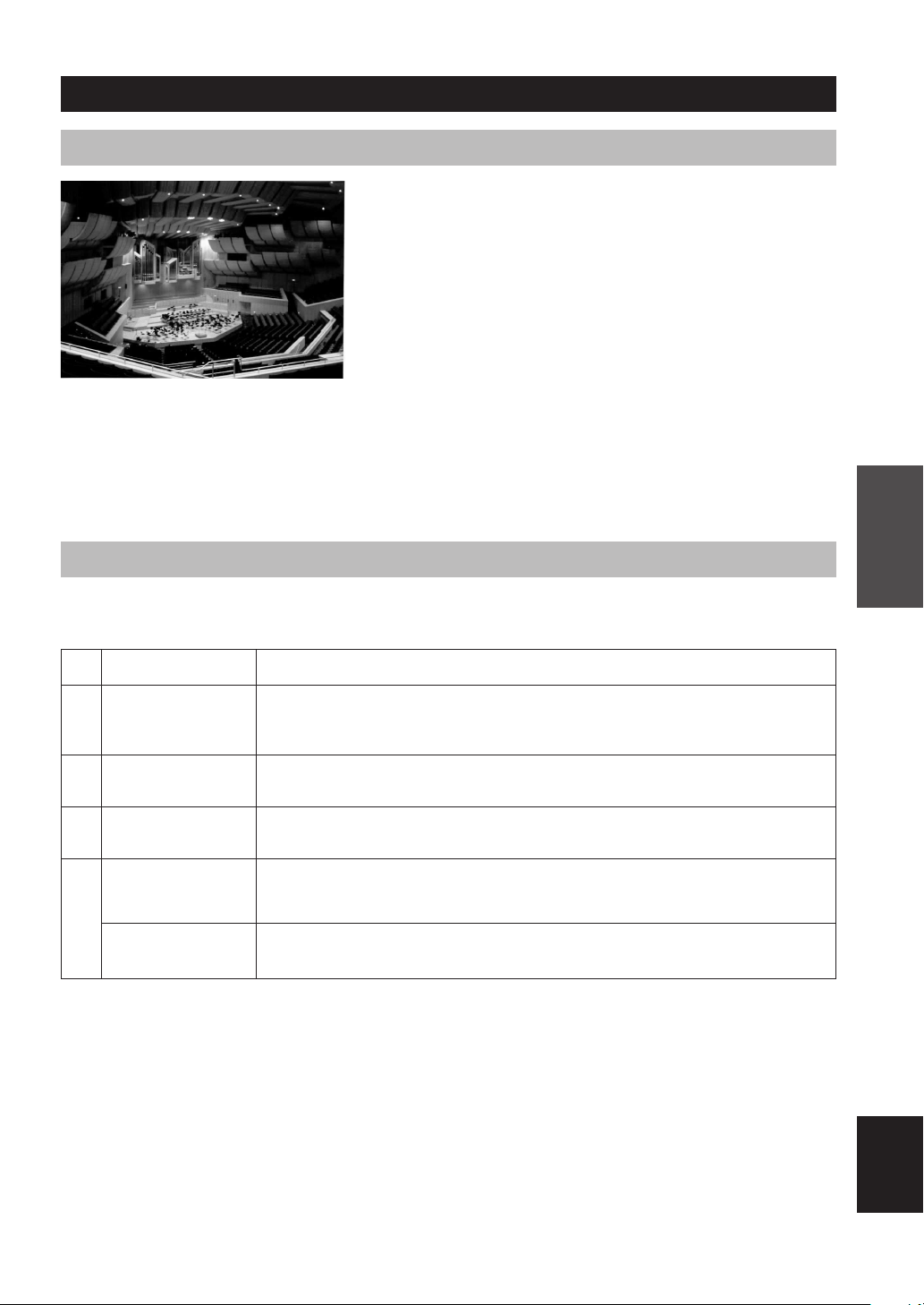
CONCERT HALL
2
JAZZ CLUB
3
ROCK CONCERT
4
ENTERTAINMENT/
Disco
ENTERTAINMENT/
5ch Stereo
Program
Features
A large round concert hall with a rich surround effect. Pronounced reflections from all directions
emphasize the extension of sounds. The sound field has a great deal of presence, and your virtual
seat is near the center, close to the stage.
This is the sound field at stage front in “The Bottom Line”, a famous New York jazz club, that
seats up to 300 people. Its wide left to right seating arrangement offers a real and vibrant sound.
The ideal program for lively, dynamic rock music. The data for this program was recorded at LA’s
“hottest” rock club. The listener’s virtual seat is at the center-left of the hall.
This program recreates the acoustic environment of a lively disco in the heart of a big city. The
sound is dense and highly concentrated. It is also characterized by a high-energy, “immediate”
sound.
Using this program increases the listening position range. This is a sound field suitable for
background music at parties, etc.
English
27
CINEMA DSP
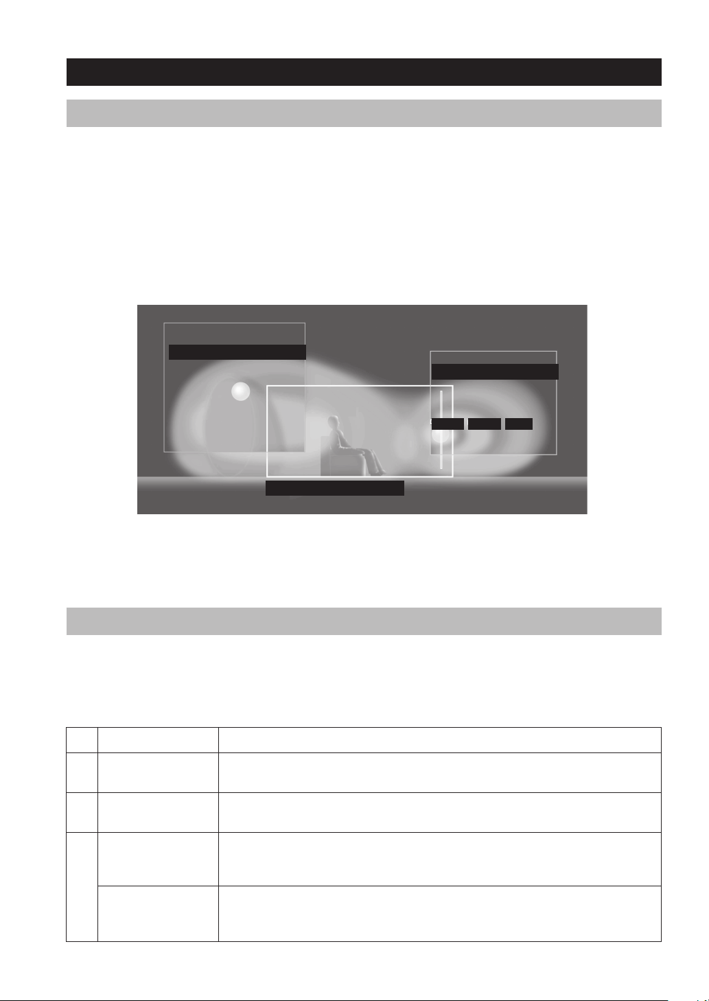
Sound design of CINEMA DSP
Filmmakers intend for the dialog to be located right on the screen, the effect sound a little farther back, the music spread
even farther back, and the surround sound around the listener. Of course, all of these sounds must be synchronized with
the images on the screen.
CINEMA DSP is an upgraded version of YAMAHA DSP specially designed for movie soundtracks. CINEMA DSP
integrates the DTS, Dolby Digital, and Dolby Pro Logic surround sound technologies with YAMAHA DSP sound field
programs to provide a surround sound field. It recreates comprehensive movie sound design in your audio room. In
CINEMA DSP sound field programs, YAMAHA’s exclusive DSP processing is added to the Front left and right, and
Center channels, so the listener can enjoy realistic dialogue, depth of sound, smooth transition between sound sources,
and a surround sound field that goes beyond the screen.
When a DTS or Dolby Digital signal is detected, the CINEMA DSP sound field processor automatically chooses the
most suitable sound field program for that signal.
L SURROUND SOUND FIELD
PRESENCE SOUND FIELD
EFFECT MUSIC
DIALOG
R SURROUND SOUND FIELD
In addition to the DSP, this unit is equipped with a variety of precise decoders; Dolby Pro Logic decoder for Dolby
Surround sources, Dolby Pro Logic II decoder for Dolby Surround and 2-channel sources, Dolby Digital/DTS decoder
for multi-channel sources and Dolby Digital + Matrix 6.1 or DTS + Matrix 6.1 decoder for adding a surround back
channel (the surround back channel is outputted from virtual surround back speaker). You can select CINEMA DSP
programs to optimize these decoders and the DSP sound patterns depending on the input source.
CINEMA DSP Programs
The following list gives you a brief description of the sound fields produced by each of the sound field programs. Keep
in mind that most of these are precise digital recreations of actual acoustic environments. Select the sound field program
that you feel sounds best regardless of the name and description given for it below.
■ For audio-video sources: No. 4 to 6
No.
4
5
6
Program
ENTERTAINMENT/
Game
MUSIC VIDEO
TV THEATER/
Mono Movie
Features
This program adds a deep and spatial feeling to video game sounds.
This program lends an enthusiastic atmosphere to the sound, giving you the feeling you are at an
actual jazz or rock concert.
This program is provided for reproducing monaural video sources (such as old movies). The
program produces the optimum reverberation to create sound depth using only the presence sound
field.
TV THEATER/Variety/
Sports
28
Though the presence sound field is relatively narrow, the surround sound field employs the sound
environment of a large concert hall. This effect enhances the experience of watching various TV
programs such as news, variety shows, music programs or sports programs.
 Loading...