

Page 1
AV Receiver
ENFRES
Ampli-tuner audio-vidéo
RX-V383/HTR-3071
Quick Start Guide
UCRABL
Safety Instructions ................................................ 2
Connections .......................................................... 5
Basic operations ................................................. 13
English
Guide de démarrage rapide
Guía de inicio rápida
Consignes de sécurité......................................... 18
Raccordements................................................... 21
Fonctionnement de base .................................... 29
Instrucciones de segurida ................................... 33
Conexiones ......................................................... 35
Operaciones básicas .......................................... 43
Français
Español
Page 2
English
CAUTION
CAUTION: TO REDUCE THE RISKOF
ELECTRIC SHOCK, DO NOT REMOVE
COVER (OR BACK). NO USER-SERVICEABLE
PARTS INSIDE. REFER SERVICING TO
QUALIFIED SERVICE PERSONNEL.
RISK OF ELECTRIC
SHOCK DO NOT OPEN
A (power) key
Turns on the power of this unit or sets it to the standby mode.
This product is for ordinary homes. Do not use for applications requiring high reliability, such as
managing lives, health care or high-value assets.
IMPORTANT SAFETY INSTRUCTIONS
• Explanation of Graphical Symbols
The lightning flash with arrowhead symbol, within an equilateral triangle, is
intended to alert you to the presence of uninsulated “dangerous voltage” within the
product’s enclosure that may be of sufficient magnitude to constitute a risk of
electric shock to persons.
For more detailed information, refer to the Owner’s Manual on the CD-ROM. To view the Owner’s
Manual, click on “English” in the screen displayed automatically when you insert the CD-ROM
into your PC, or click on the model name if the screen to select models is displayed, and then click
on “English” in the next screen. Then, follow the onscreen instructions.
If the screen is not displayed automatically, open the “index.html” in the CD-ROM.
Caution: Do not attempt to play this CD-ROM in an audio player.
The Owner’s Manual contained in the CD-ROM can be downloaded from the following website.
http://download.yamaha.com/
8 Do not install near any heat sources such as radiators, heat registers, stoves, or other apparatus
(including amplifiers) that produce heat.
9 Do not defeat the safety purpose of the polarized or grounding-type plug. A polarized plug has two
blades with one wider than the other. A grounding type plug has two blades and a third grounding
prong. The wide blade or the third prong are provided for your safety. If the provided plug does not
fit into your outlet, consult an electrician for replacement of the obsolete outlet.
10 Protect the power cord from being walked on or pinched particularly at plugs, convenience
receptacles, and the point where they exit from the apparatus.
11 Only use attachments/accessories specified by the manufacturer.
12 Use only with the cart, stand, tripod, bracket, or table specified by the
manufacturer, or sold with the apparatus. When a cart is used, use caution when
moving the cart/apparatus combination to avoid injury from tip-over.
13 Unplug this apparatus during lightning storms or when unused for long periods of
time.
14 Refer all servicing to qualified service personnel. Servicing is required when the
apparatus has been damaged in any way, such as power-supply cord or plug is damaged, liquid has
been spilled or objects have fallen into the apparatus, the apparatus has been exposed to rain or
moisture, does not operate normally, or has been dropped.
The exclamation point within an equilateral triangle is intended to alert you to the
presence of important operating and maintenance (servicing) instructions in the
literature accompanying the appliance.
1 Read these instructions.
2 Keep these instructions.
3 Heed all warnings.
4 Follow all instructions.
5 Do not use this apparatus near water.
6 Clean only with dry cloth.
7 Do not block any ventilation openings. Install in accordance with the manufacturer’s instructions.
2 En
Page 3

FCC INFORMATION (for US customers)
1 IMPORTANT NOTICE: DO NOT MODIFY THIS UNIT!
This product, when installed as indicated in the instructions contained in this manual, meets FCC
requirements. Modifications not expressly approved by Yamaha may void your authority,
granted by the FCC, to use the product.
2 IMPORTANT: When connecting this product to accessories and/or another product use only
high quality shielded cables. Cable/s supplied with this product MUST be used. Follow all
installation instructions. Failure to follow instructions could void your FCC authorization to use
this product in the USA.
3 NOTE: This product has been tested and found to comply with the requirements listed in FCC
Regulations, Part 15 for Class “B” digital devices. Compliance with these requirements provides
a reasonable level of assurance that your use of this product in a residential environment will not
result in harmful interference with other electronic devices.
This equipment generates/uses radio frequencies and, if not installed and used according to the
instructions found in the users manual, may cause interference harmful to the operation of other
electronic devices.
Compliance with FCC regulations does not guarantee that interference will not occur in all
installations. If this product is found to be the source of interference, which can be determined by
turning the unit “OFF” and “ON”, please try to eliminate the problem by using one of the following
measures:
Relocate either this product or the device that is being affected by the interference.
Utilize power outlets that are on different branch (circuit breaker or fuse) circuits or install AC line
filter/s.
In the case of radio or TV interference, relocate/reorient the antenna. If the antenna lead-in is 300
ohm ribbon lead, change the lead-in to coaxial type cable.
If these corrective measures do not produce satisfactory results, please contact the local retailer
authorized to distribute this type of product. If you can not locate the appropriate retailer, please
contact Yamaha Corporation of America A/V Division, 6600 Orangethorpe Avenue, Buena Park,
CA 90620, USA.
The above statements apply ONLY to those products distributed by Yamaha Corporation of
America or its subsidiaries.
IMPORTANT
Please record the serial number of this unit in the space below.
MODEL:
Serial No.:
The serial number is located on the rear of the unit. Retain this Owner's Manual in a safe place for
future reference.
COMPLIANCE INFORMATION STATEMENT (DECLARATION OF CONFORMITY
PROCEDURE)
Responsible Party: Yamaha Corporation of America A/V Division
Address: 6600 Orangethorpe Avenue, Buena Park, CA 90620
Telephone: 714-522-9011
Type of Equipment: AV Receiver
Model Name: RX-V383, HTR-3071
This device complies with Part 15 of FCC Rules and Industry Canada licence-exempt RSS standard(s).
Operation is subject to the following two conditions:
(1) this device may not cause interference, and
(2) this device must accept any interference, including interference that may cause undesired operation
of this device.
FCC CAUTION
Changes or modifications not expressly approved by the party responsible for compliance could
void the user’s authority to operate the equipment.
NOTICE
This equipment has been tested and found to comply with the limits for a Class B digital device,
pursuant to part 15 of the FCC Rules. These limits are designed to provide reasonable protection
against harmful interference in a residential installation. This equipment generates, uses and can
radiate radio frequency energy and, if not installed and used in accordance with the instructions,
may cause harmful interference to radio communications. However, there is no guarantee that
interference will not occur in a particular installation. If this equipment does cause harmful
interference to radio or television reception, which can be determined by turning the equipment off
and on, the user is encouraged to try to correct the interference by one or more of the following
measures:
– Reorient or relocate the receiving antenna.
– Increase the separation between the equipment and receiver.
– Connect the equipment into an outlet on a circuit different from that to which the receiver is
connected.
– Consult the dealer or an experienced radio/TV technician for help.
This equipment complies with FCC/IC radiation exposure limits set forth for an uncontrolled
environment and meets the FCC radio frequency (RF) Exposure Guidelines and RSS-102 of the IC
radio frequency (RF) Exposure rules. This equipment should be installed and operated keeping the
radiator at least 20cm or more away from person’s body.
FOR CANADIAN CUSTOMERS
CAN ICES-3(B)/NMB-3(B).
This transmitter must not be co-located or operated in conjunction with any other antenna or
transmitter.
Do not use this unit within 22 cm (9 inches) of persons with a heart pacemaker implant or
defibrillator implant.
En 3
Page 4

CAUTION: READ THIS BEFORE OPERATING YOUR UNIT.
1 To assure the finest performance, please read this manual carefully. Keep it in a safe place for future
reference.
2 Install this sound system in a well ventilated, cool, dry, clean place - away from direct sunlight, heat
sources, vibration, dust, moisture, and/or cold. For proper ventilation, allow the following minimum
clearances.
Top: 30 cm, Rear: 20 cm, Sides: 20 cm
3 Locate this unit away from other electrical appliances, motors, or transformers to avoid humming
sounds.
4 Do not expose this unit to sudden temperature changes from cold to hot, and do not locate this unit in
an environment with high humidity (i.e. a room with a humidifier) to prevent condensation inside
this unit, which may cause an electrical shock, fire, damage to this unit, and/or personal injury.
5 Avoid installing this unit where foreign object may fall onto this unit and/or this unit may be exposed
to liquid dripping or splashing. On the top of this unit, do not place:
– Other components, as they may cause damage and/or discoloration on the surface of this unit.
– Burning objects (i.e. candles), as they may cause fire, damage to this unit, and/or personal injury.
– Containers with liquid in them, as they may fall and liquid may cause electrical shock to the user
and/or damage to this unit.
6 Do not cover this unit with a newspaper, tablecloth, curtain, etc. in order not to obstruct heat
radiation.
If the temperature inside this unit rises, it may cause fire, damage to this unit, and/or personal injury.
7 Do not plug in this unit to a wall outlet until all connections are complete.
8 Do not operate this unit upside-down. It may overheat, possibly causing damage.
9 Do not use force on switches, knobs and/or cords.
10 When disconnecting the power cable from the wall outlet, grasp the plug; do not pull the cable.
11 Do not clean this unit with chemical solvents; this might damage the finish. Use a clean, dry cloth.
12 Only voltage specified on this unit must be used. Using this unit with a higher voltage than specified
is dangerous and may cause fire, damage to this unit, and/or personal injury. Yamaha will not be
held responsible for any damage resulting from use of this unit with a voltage other than specified.
13 To prevent damage by lightning, keep the power cable and outdoor antennas disconnected from a
wall outlet or this unit during a lightning storm.
14 Do not attempt to modify or fix this unit. Contact qualified Yamaha service personnel when any
service is needed. The cabinet should never be opened for any reasons.
15 When not planning to use this unit for long periods of time (i.e. vacation), disconnect the AC power
plug from the wall outlet.
16 Be sure to refer to the “Troubleshooting” section of the Owner’s Manual on the CD-ROM for
common operating errors before concluding that this unit is faulty.
17 Before moving this unit, press z to set it to standby mode and disconnect the AC power plug from
the wall outlet.
18 VOLTAGE SELECTOR (Taiwan, Brazil and General models)
The VOLTAGE SELECTOR on the rear panel of this unit must be set for your local main voltage
BEFORE plugging into the AC wall outlet. Voltages are:
........................................................................................................... AC 110-120/220-240V, 50/60Hz
19 Condensation will form when the surrounding temperature changes suddenly. Disconnect the power
cable from the outlet, then leave this unit alone.
20 When using this unit for a long time, this unit may become warm. Turn the power off, then leave this
unit alone for cooling.
21 Install this unit near the AC outlet and where the AC power plug can be reached easily.
22 Excessive sound pressure from earphones and headphones can cause hearing loss.
This unit is not disconnected from the AC power source as long as it is connected to the wall outlet,
even if this unit itself is turned off by A. This state is called the standby mode. In this state, this unit
is designed to consume a very small quantity of power.
WARNING
TO REDUCE THE RISK OF FIRE OR ELECTRIC SHOCK, DO NOT EXPOSE THIS UNIT TO
RAIN OR MOISTURE.
■ Notes on remote controls and batteries
• Do not spill water or other liquids on the remote control.
• Do not drop the remote control.
• Do not leave or store the remote control in the following conditions:
– places of high humidity, such as near a bath
– places of high temperatures, such as near a heater or stove
– places of extremely low temperatures
– dusty places
• Insert the battery according to the polarity markings (+ and –).
• Change all batteries if you notice the following conditions:
– the operation range of the remote control narrows
– the transmit indicator does not flash or is dim
• If the batteries run out, immediately remove them from the remote control to prevent an explosion
or acid leak.
• If you find leaking batteries, discard the batteries immediately, taking care not to touch the leaked
material. If the leaked material comes into contact with your skin or gets into your eyes or mouth,
rinse it away immediately and consult a doctor. Clean the battery compartment thoroughly before
installing new batteries.
• Do not use old batteries together with new ones. This may shorten the life of the new batteries or
cause old batteries to leak.
• Do not use different types of batteries (such as alkaline and manganese batteries) together.
Specification of batteries may be different even though they look the same.
• Before inserting new batteries, wipe the compartment clean.
• If the remote control is without batteries for more than 2 minutes, or if exhausted batteries remain in
the remote control, the contents of the memory may be cleared. In such a case, install new batteries
and set the remote control code.
• Dispose of batteries according to your regional regulations.
• Keep batteries away from children. If a battery is accidentally swallowed, contact your doctor
immediately.
• When not planning to use the remote control for long periods of time, remove the batteries from the
remote control.
• Do not charge or disassemble the supplied batteries.
• The batteries shall not be exposed to excessive heat such as sunshine, fire or like.
4 En
Page 5
This document explains basic speaker system setup and unit configuration,
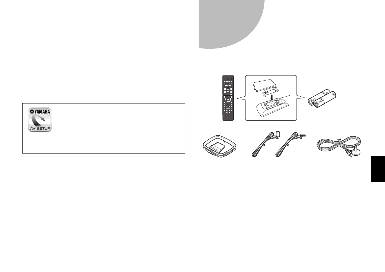
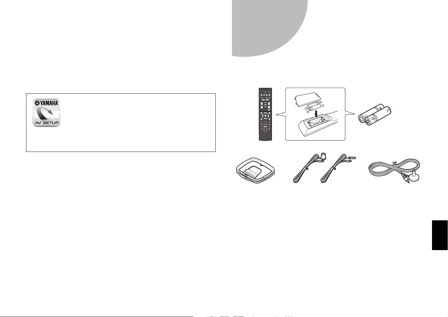
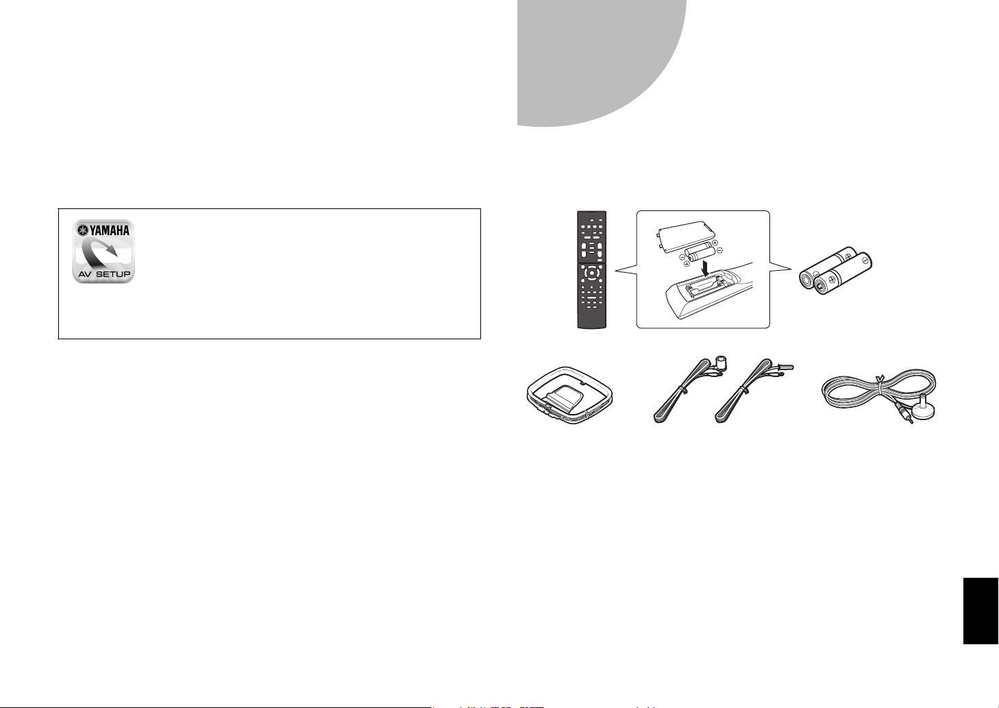
Remote control
Batteries (AAA, R03, UM-4)
(x2)
AM antenna FM antenna
CD-ROM (Owner’s Manual)
Quick Start Guide (this booklet)
YPAO microphone
One of the above is supplied
depending on the region of purchase.
followed by step-by-step instructions. Basic operations, such as playing
Blu-ray Discs, DVDs, and radio content, are also explained.
The unit is equipped with a number of other functions not described in this
booklet. For more information about this product, refer to the Owner’s Manual
included on the supplied CD-ROM. The latest Owner’s Manual can be
downloaded from the following website.
http://download.yamaha.com/
[For U.S. customers only]
Visit the following website for additional information, FAQ’s, downloads such
as “Owner’s Manual” and product updates.
http://usa.yamaha.com/support/
AV SETUP GUIDE
AV SETUP GUIDE is an app that guides you
through the process of connecting a TV or playback
device, such as a BD/DVD or CD player, and
speakers to the AV receiver. Search “AV SETUP
GUIDE” on the App Store or Google Play for
details.
Preparation
1
Confirming package contents
Preparing cables
The following cables (not supplied) are required to build the system described
in this document.
• Speaker cables (depending on the number of speakers)
• Audio pin cable (x1)
• HDMI cables (x3)
En 5
Page 6
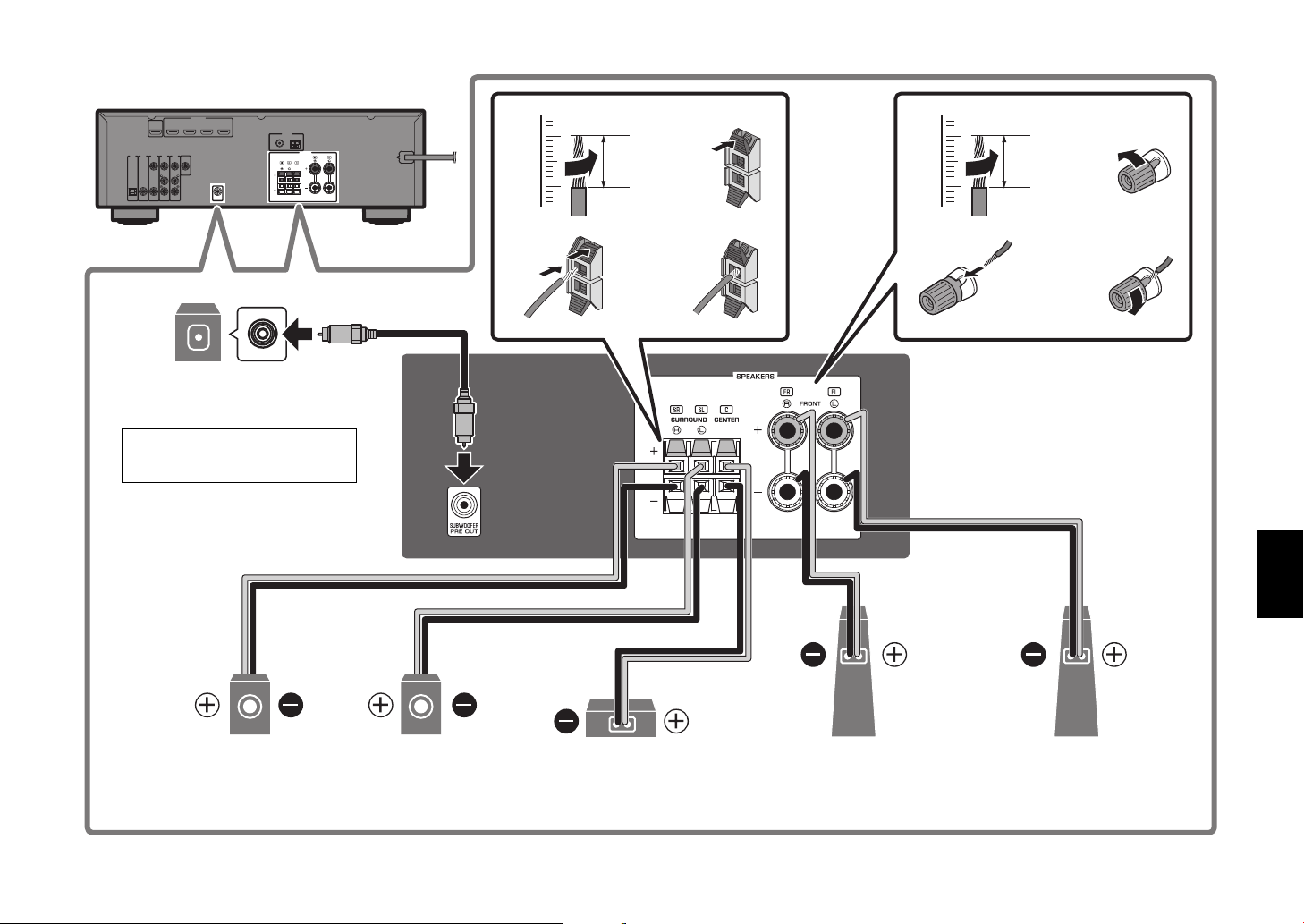
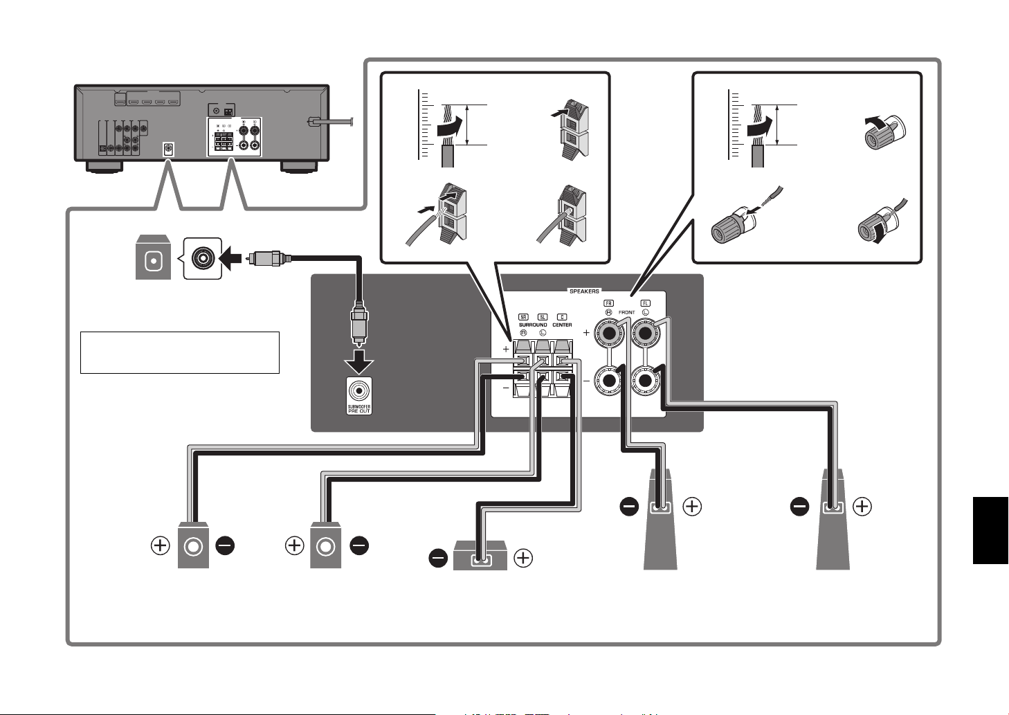
Connecting speakers/subwoofer
5
4
21
3
9
10° to 30° 10° to 30°
10 mm
(3/8")
2
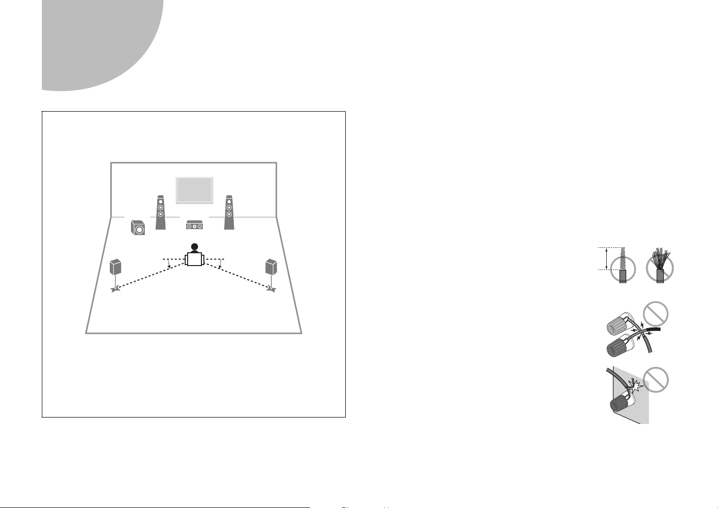
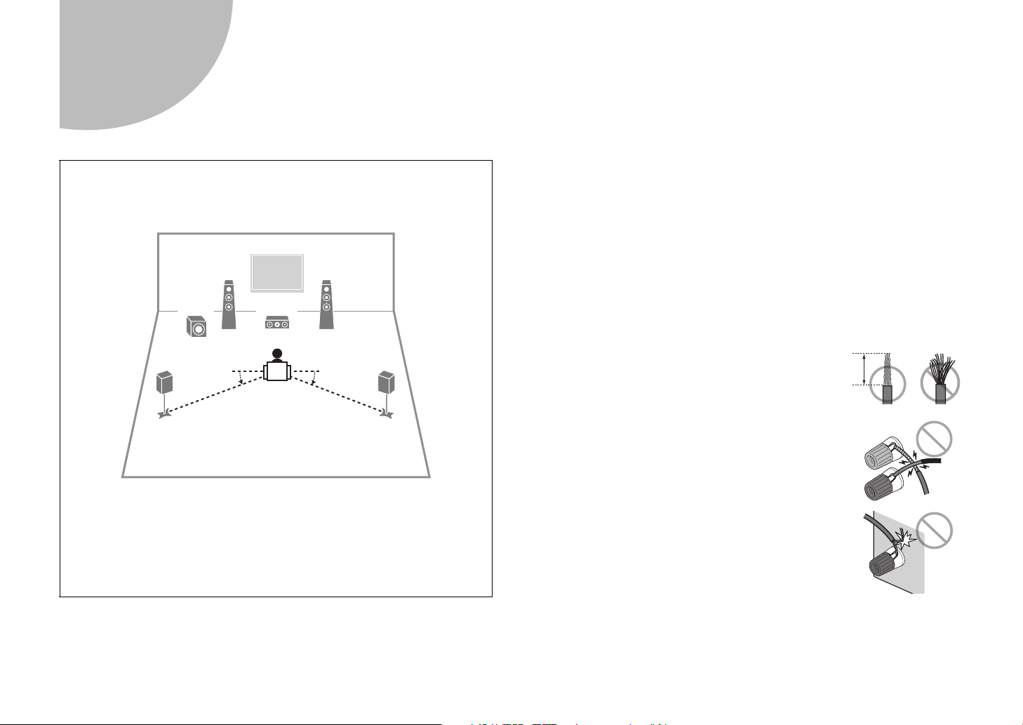
Positioning speakers
Use the diagram as a reference for positioning speakers.
When connecting 6-ohm speakers
(U.S.A. and Canada models only)
Set the unit’s speaker impedance to “6 Ω MIN”. For details, see “Setting the
speaker impedance” in the Owner’s Manual.
Precautions for connecting speaker cables
• Be sure that the unit and subwoofer are turned off.
• Prepare speaker cables in a place away from the unit, to avoid accidentally
dropping wire strands into the unit's interior which could result in a short
circuit or malfunction of the unit.
• Improper connection of speaker cables could cause a short circuit resulting
in damage to, or malfunctioning of, the unit or speakers.
– Carefully remove approximately 10 mm
(3/8") of insulation from the speakerconnection ends of the cables, and twist
the bare wires of each speaker cable
together firmly.
– Do not allow the bare wires of separate speaker
cables to come into contact with one another.
6 En
1 Front speaker (L)
2 Front speaker (R)
3 Center speaker
4 Surround speaker (L)
5 Surround speaker (R)
9 Subwoofer
– Do not allow speaker cable bare wires to come into
contact with metal parts on the unit (rear panel and
screws).
If “Check SP Wires” is shown on the front display when the unit is turned on,
turn off the unit and be sure that speaker cables have not caused a short
circuit.
Page 7
2
34
12
34
1
9
Subwoofer
2
Front speaker (R)
10 mm
(3/8")
1
Front speaker (L)
3
Center speaker
5
Surround speaker (R)
4
Surround speaker (L)
Use a subwoofer equipped with
built-in amplifier.
Audio pin cable
10 mm
(3/8")
En 7
Page 8

3
HDMI
HDMI HDMI
(BD/DVD)
2
3
1
HDMI
(HDCP2.2)
4
HDCP2.2
ARC
HDMI OUT
HDMI HDMI HDMI
HDMI
HDMI
HDMI
TV BD/DVD player Satellite/cable set top box
HDMI input
HDMI output HDMI output
Connecting external devices
8 En
Page 9
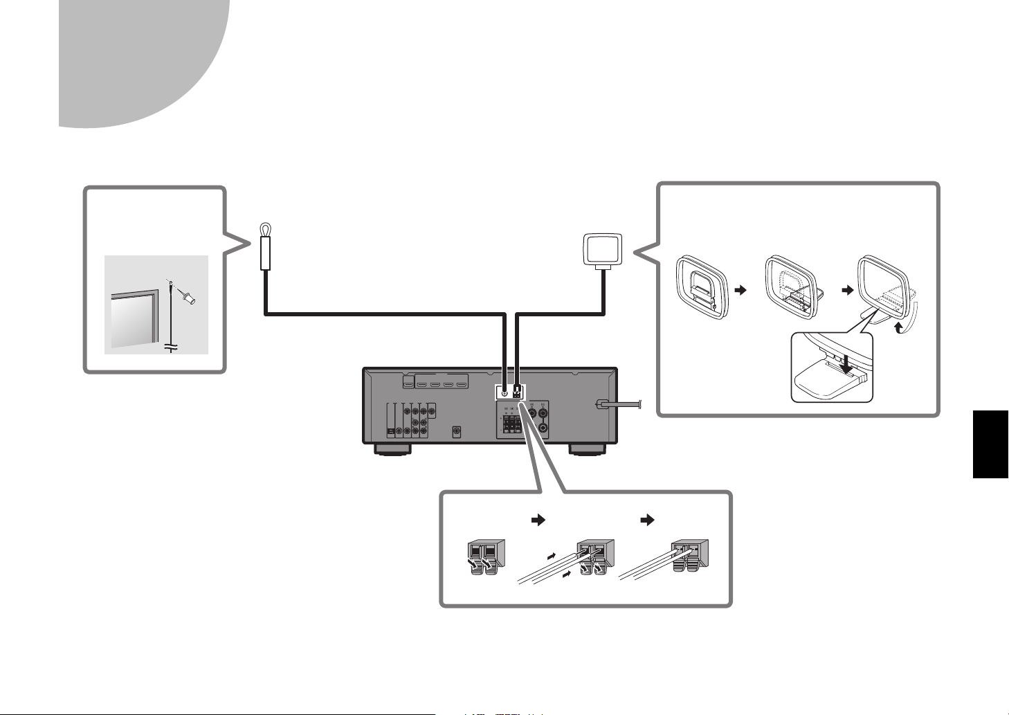
4
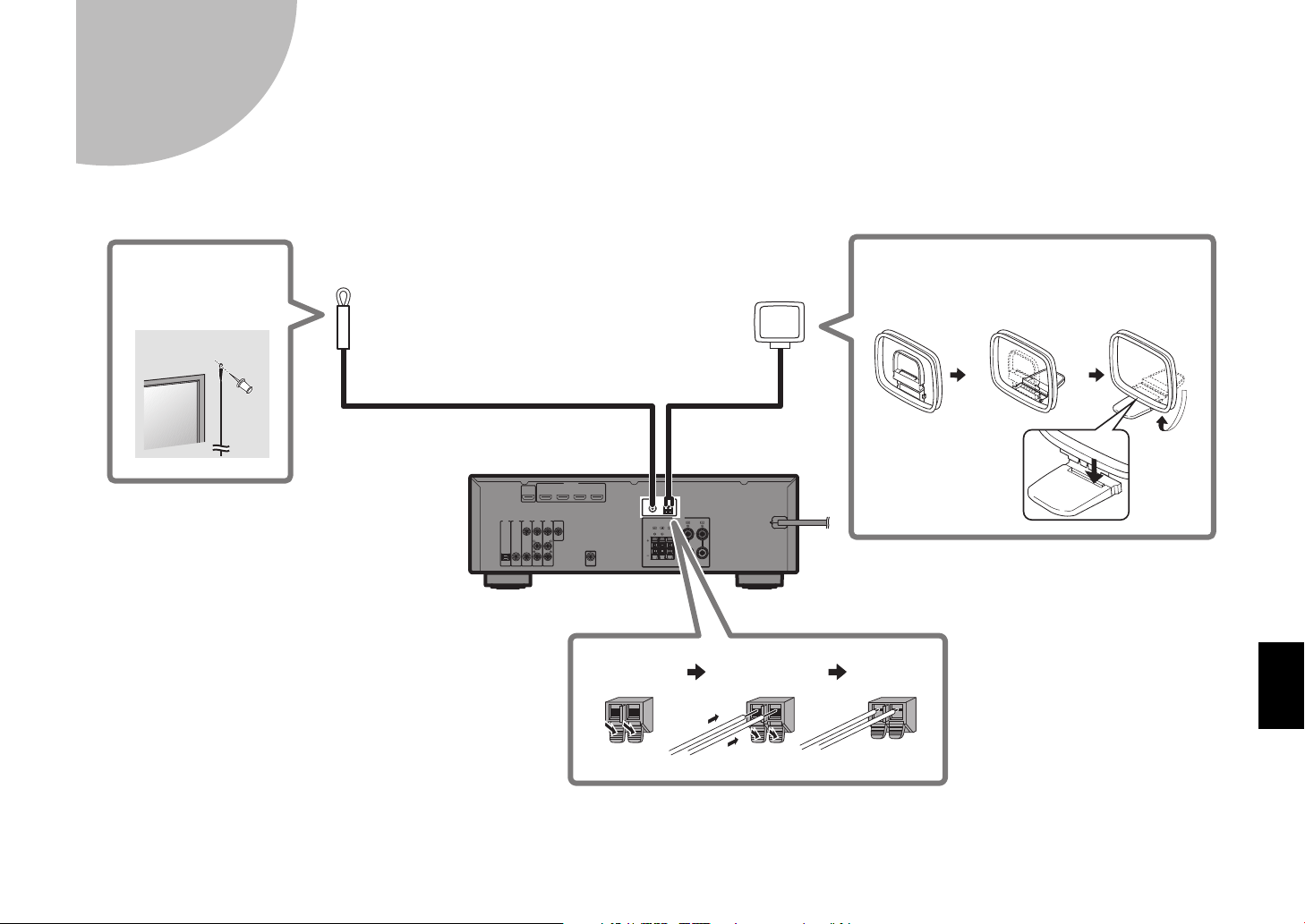
FM antenna (supplied)
AM antenna (supplied)
Hold down Insert Release
Assembling the AM antenna
Place the AM
antenna on a flat
surface.
Fix the end of the
FM antenna to a
wall.
Connecting the FM/AM antennas
En 9
Page 10
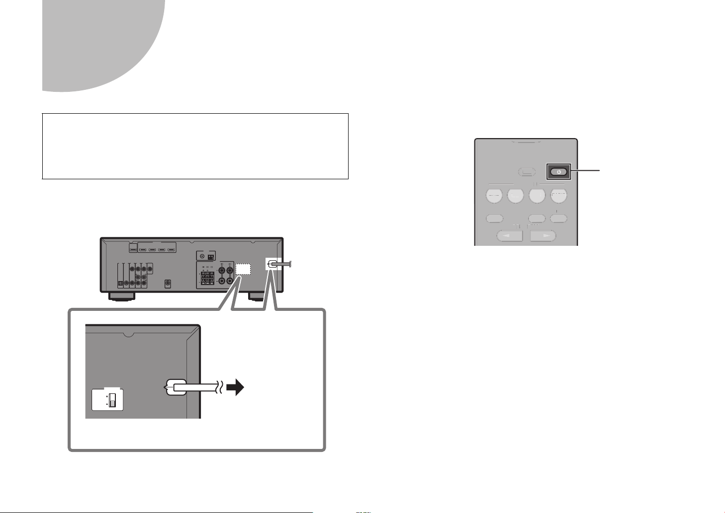
Connecting the power cable to an AC wall outlet,
To an AC wall
outlet
VOLTAGE SELECTOR
(Taiwan, Brazil and General models only)
PROGRAM
STRAIGHT
ENHANCER BASS
BD
DVD
TV
SCENE
RADIO
SLEEP
CD
G
S
T
R
T
E
B
A
SS
BD
T
V
R
ADIO
S
CD
z
5
and turning on the unit
Before connecting the power cable
(Taiwan, Brazil and General models only)
Set the switch position of VOLTAGE SELECTOR according to your local
voltage.
Voltages are AC 110–120/220–240 V, 50/60 Hz.
1 Plug the power cable into an AC wall outlet.
2 Press z (receiver power) to turn on the unit.
LEEP
SCEN
AIGH
NHANCER
O
3 Turn on the TV and switch the TV input to display
video from the unit (HDMI OUT jack).
10 En
VOLTAGE
SELECTOR
110V120V
220V240V
Page 11
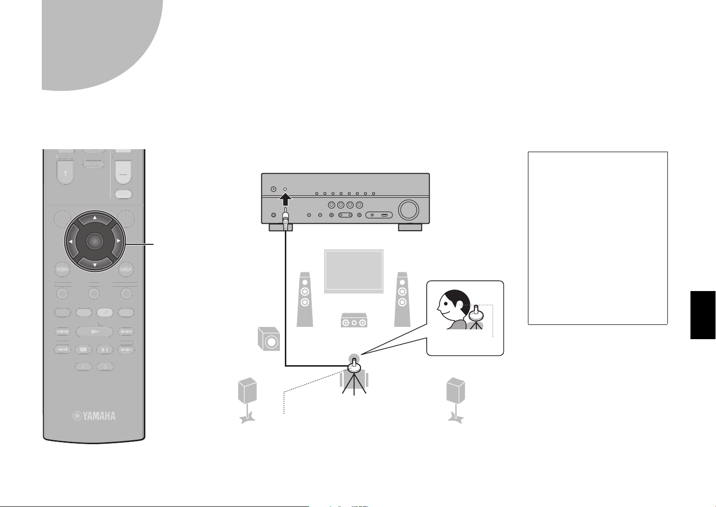
Optimizing the speaker settings automatically
12
3
9
54
TUNING
PRESET
MUTE
TUNING
MEMORY
TOP MENU
HOME
POP-UP/MENU
DISPLAYRETURN
SETUP
OPTION
VOLUME
USB
INPUT
ENTER
BLUE
YELLOWGREEN
RED
BLUETOOTH
T
MUTE
U
E
POP-UP/
U
SETUP
O
OPTION
USB
U
BLUE
O
G
BLUEO
O
ENTER
Note the following regarding
YPAO measurement
• Test tones are output at high
volume and may surprise or
frighten small children.
• Test tone volume cannot be
adjusted.
• Keep the room as quiet as
possible.
• Stay in a corner of the room
behind the listening position
so that you do not become an
obstacle between speakers
and the YPAO microphone.
• Do not connect headphones.
Ear height
Listening position
YPAO microphone
Cursor keys
6
(YPAO)
The Yamaha Parametric room Acoustic Optimizer (YPAO) function detects speaker connections, measures the distances from them to your listening position(s),
and then automatically optimizes the speaker settings, such as volume balance and acoustic parameters, to suit your room.
OLUME
TOP MEN
TUNING
HOM
MEN
MEMO
PRESE
TUNING
En 11
Page 12
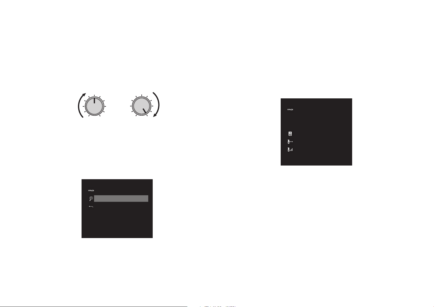
1 Turn on the subwoofer and set the volume to half.
VOLUME
CROSSOVER/
HIGH CUT
MIN MAX
MIN MAX
Auto Setup
Start
Exit
Auto Setup
Measurement Finished
Result
3/2/0.1ch
3.0/10.5m
-3.0/+10.0dB
OK : ENTER
If the crossover frequency is adjustable, set it to maximum.
2 Place the YPAO microphone at your listening
position and connect it to the YPAO MIC jack on
the front panel.
The screen below appears on the TV.
12 En
Note
Place the YPAO microphone at your listening position (same height as your ears).
We recommend the use of a tripod as a microphone stand. You can use the tripod
screws to stabilize the microphone.
3 Press ENTER.
The measurement will start in 10 seconds.
It takes about 3 minutes to measure.
The screen below appears on the TV when the measurement finishes.
Note
If an error message (such as E-1) or warning message (such as W-2) appears,
see “Error messages” or “Warning messages” under “Optimizing the speaker
settings automatically (YPAO)” in the Owner’s Manual.
4 Confirm the results displayed on the screen and
press ENTER.
5 Use the cursor keys (e/r) to select “SAVE” (Save)
and press ENTER.
6 Disconnect the YPAO microphone from the unit.
This completes optimization of the speaker settings.
Page 13
Basic operations
MUTE
SETUP
OPTION
FM/AM
VOLUME
PROGRAM
USB
STRAIGHT
ENHANCER BASS
INPUT
BD
DVD
TV
SCENE
RADIO
SLEEP
CD
BLUETOOTH
SETUP
O
OPTION
S
P
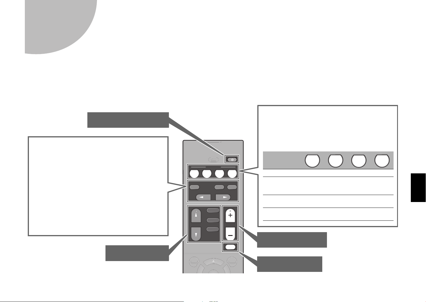
The unit is equipped with a variety of sound
programs and surround decoders that allow you to
enjoy playback sources in your favorite sound
mode.
STRAIGHT: Input sources will be played without any
sound field effects.
ENHANCER: Compressed music stored on a
Bluetooth device or USB storage device will be played
with additional depth and breadth.
BASS: Extra bass allows you to enjoy enhanced bass
sounds.
PROGRAM (e/r): Sound programs suitable for
movies, music and stereo playback can be selected.
Unit input sources and settings that have been
assigned to SCENE keys can be selected with just
one touch (SCENE function).
The unit turns on automatically when it is in standby
mode. By default, the following settings assigned to
each SCENE key.
SCENE key
Input HDMI1 AUDIO1 AUDIO2 TUNER
Sound program
MOVIE
(Sci-Fi)
STRAIGHT STRAIGHT
STEREO
(5ch
Stereo)
Compressed
Music Enhancer
Off On Off On
SCENE link
playback
On On Off Off
BD
DVD
TV
CD
RADIO
Adjust the volume level
Select an input source
Mute the audio output
Turn on/off (standby) the unit
This section describes basic operations such as playing Blu-ray Discs and DVDs, and tuning into radio stations. Most operations can be performed using the
remote control.
Operating the remote control
LEE
En 13
Page 14
Playing a BD/DVD
MUTE
ENHANCER
STEREO
TUNED
SLEEP
ECO
CHARGE
ADAPTIVE DRC
VIRTUAL
BD Player
VOL.
OUT
Input source Device name
TUNING
PRESET
MUTE
TUNING
MEMORY
TOP MENU
HOME
POP-UP/MENU
DISPLAYRETURN
SETUP
OPTION
FM/AM
VOLUME
PROGRAM
USB
STRAIGHT
ENHANCER BASS
INPUT
BD
DVD
TV
SCENE
RADIO
SLEEP
ENTER
BLUE
YELLOWGREEN
RED
CD
BLUETOOTH
G
PRESET
G
O
R
O
E
P
SETUP
O
OPTION
O
P
ROGRAM
US
E
S
D
VD
SC
E
O
S
G
RED
C
BLUETO
O
TH
VOLUME
( / )
INPUT
(q/w)
STRAIGHT
TUNIN
P MENU
LEEP
EN
NHANCER
FM/AM
B
HOM
MEM
ADI
D
MUTE
OP-UP/MENU
BLUE
Y
TUNIN
We recommend playing back multichannel audio (5.1-channel or more) to feel surround sound produced by the unit.
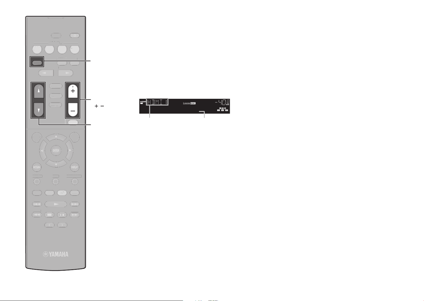
1 Turn on the BD/DVD player.
S
2 Press INPUT (q/w) repeatedly to
select “HDMI 1”.
The name of the connected device such as “BD
3 Start playback on the BD/DVD
player.
4 Press STRAIGHT to select
“STRAIGHT”.
player” may be displayed.
Note
When “STRAIGHT” (straight decode) is enabled, each
speaker produces each channel audio signal directly
(without sound field processing).
5 Press VOLUME to adjust the
volume.
Note
When sound is not heard, or no sound is output from a specific
speaker, see “Troubleshooting” in the Owner’s Manual.
14 En
Page 15
ENHANCER
LINK
ECO
MASTER
OUT
2
-
R
es
Hi
YPAO
VOL.
A-DRC
SLEEP
PART Y
ZONE
A2B3
FPR
SBL SB SBR
FPL
MUTE VIRTUAL
VOL.
SLSWSR
STEREO
TUNED
FM 98.50MHz
TUNING
PRESET
MUTE
TUNING
MEMORY
TOP MENU
HOME
POP-UP/MENU
DISPLAYRETURN
SETUP
OPTION
FM/AM
VOLUME
PROGRAM
USB
STRAIGHT
ENHANCER BASS
INPUT
BD
DVD
TV
SCENE
RADIO
SLEEP
ENTER
BLUE
YELLOWGREEN
RED
CD
BLUETOOTH
MUTE
T
O
U
HO
SETUP
O
OPTION
OLU
G
USB
S
T
R
AIGHT
B
A
SS
U
BD
T
R
ADIO
S
BLUE
O
G
CD
BLUEO
O
FM/AM
TUNING
V
LEEP
SCEN
O
ENHANCER
ME
Listening to FM/AM radio
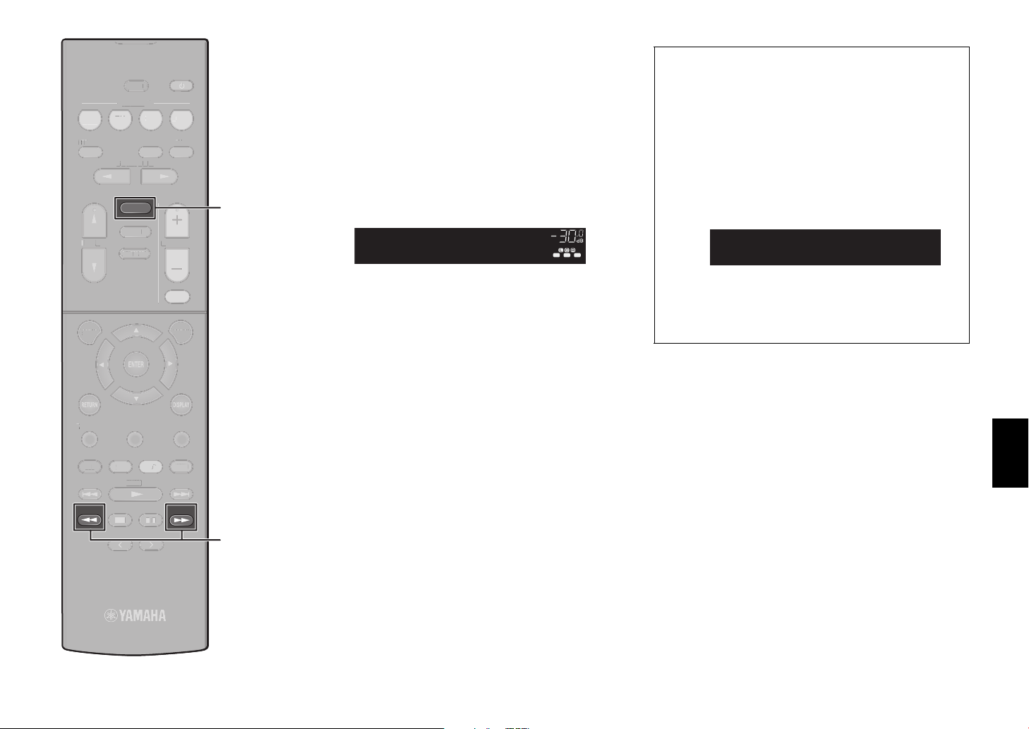
1 Press FM/AM to select a band.
“TUNER” is selected as the input source and then
the frequency currently selected is displayed.
2 Press TUNING repeatedly to set a
frequency.
Hold down the key for about a second to search
stations automatically.
“TUNED” lights up when the unit is receiving an FM/
AM radio station signal.
“STEREO” lights up when the unit is receiving a
stereo FM radio signal.
Setting the frequency steps (Asia, Taiwan, Brazil
and General models only)
At the factory, the frequency step setting is set to 50 kHz
for FM and 9 kHz for AM.
Depending on your country or region, set the frequency
steps to 100 kHz for FM and 10 kHz for AM.
1 Set the unit to standby mode.
2 Hold down STRAIGHT on the front panel and press
z (power).
3 Press PROGRAM on the front panel repeatedly to
select “TU”.
MASTER
LINK
2
OUT
ECO
-
ResHi
TU••••FM50/AM9
4 Press STRAIGHT on the front panel to select
“FM100/AM10”.
5 Press z (power) to set the unit to standby mode and
turn it on again.
STEREO
SLEEP
ENHANCER
ZONE
TUNED
A2B3
PARTY
A-DRC
VOL.
YPAO
VOL.
MUTE VIRTUAL
FPR
FPL
SR
SW
SL
SBL SB SBR
P MEN
MEMO
PRESET
ME
POP-UP/MENU
En 15
Page 16

RADIO
USB flash drive
TUNING
PRESET
MUTE
TUNING
MEMORY
TOP MENU
HOME
POP-UP/MENU
DISPLAYRETURN
SETUP
OPTION
FM/AM
VOLUME
PROGRAM
USB
STRAIGHT
ENHANCER BASS
INPUT
BD
DVD
TV
SCENE
RADIO
SLEEP
ENTER
BLUE
YELLOWGREEN
RED
CD
BLUETOOTH
G
MUTE
G
T
O
U
HO
SETUP
O
OPTION
FM/
OLU
G
S
T
R
AIGHT
B
A
SS
U
BD
T
R
ADIO
S
BLUE
O
G
CD
USB
BLUETOOTH
ENTER
MEMORY
TUNIN
P MEN
LEEP
SCEN
V
ENHANCER
O
AM
ME
PRESET
ME
Cursor
keys
POP-UP/MENU
TUNIN
Playing music stored on a
Bluetooth
®
device
1 Press BLUETOOTH to select
“Bluetooth” as the input source.
2 Hold down MEMORY for more than
3 seconds.
“Searching…” appears in the front display.
3 Turn on the BLUETOOTH function
on your device, and select the
model name of the unit from the
BLUETOOTH device list on your
device.
If the pass key is required, enter the number “0000”.
When the connection is established, the
indicator will glow in the front display.
4 Select a song and start playback on
the Bluetooth device.
Note
Audio playing on the unit can be transmitted to Bluetooth
wireless speakers or headphones (except when Bluetooth is
selected as the unit’s input source). See “Enjoying audio using
Bluetooth speakers/headphones” in the Owner’s Manual for
more information.
Playing music stored on a
USB flash drive
1 Connect the USB flash drive to the
USB jack.
AUX
STRAIGHT
Note
Connect the USB flash drive directly to the USB jack. Do
not use an extension cable.
USB
AUDIO
2 Press USB to select “USB” as the
input source.
The browse screen is displayed on the TV.
3 Use the cursor keys to select an
item and press ENTER.
When a song is selected, playback starts and the
playback screen is displayed.
16 En
Page 17

En 17
Page 18

Français
ATTENTION
ATTENTION: POUR RÉDUIRE LES RISQUES D’INCENDIE ET DE
DÉCHARGE ELECTRIQUE, NE PAS RETIRER LE COUVERCLE
(OU LE PANNEAU ARRIÈRE). NE CONTIENT AUCUNE PIÈCE
INTERNE RÉPARABLE PAR L’UTILISATEUR. POUR
L’ENTRETIEN, S’ADRESSER À UN PERSONNEL QUALIFIÉ.
RISQUE DE CHOC ÉLECTRIQUE:
NE PAS OUVRIR
Touche A (alimentation)
Mettez l’appareil sous tension ou réglez-le en mode de mise en veille.
Ce produit est conçu pour un usage courant dans les résidences standard. Ne l'utilisez pas pour des
applications nécessitant une haute fiabilité, telles que la gestion des gestes essentiels à la vie, des
soins de santé ou des biens de grande valeur.
PRÉCAUTIONS CONCERNANT LA SÉCURITÉ
• Explication des symboles
L’éclair avec une flèche à l’intérieur d’un triangle équilatéral est destiné à attirer
l’attention de l’utilisateur sur la présence d’une « tension dangereuse » non isolée à
l’intérieur de l’appareil, pouvant être suffisamment élevée pour constituer un risque
d’électrocution.
Le point d’exclamation à l’intérieur d’un triangle équilatéral est destiné à attirer
l’attention de l’utilisateur sur la présence d’instructions importantes sur l’emploi ou
la maintenance (réparation) de l’appareil dans la documentation fournie.
Pour de plus amples informations, reportez-vous au Mode d’emploi qui se trouve sur le CD-ROM.
Pour afficher le Mode d’emploi, cliquez sur « Français » sur l’écran qui s’affiche automatiquement
lorsque vous insérez le CD-ROM dans votre PC ou cliquez sur le nom du modèle si l’écran pour
sélectionner les modèles s’affiche, ensuite, cliquez sur « Français » sur l’écran suivant. Ensuite,
suivez les instructions à l’écran.
Si l’écran ne s’affiche pas automatiquement, ouvrez le fichier « index.html » sur le CD-ROM.
Attention : N’essayez pas de lire ce CD-ROM dans un lecteur audio.
Vous pouvez télécharger le Mode d’emploi inclus sur le CD-ROM sur le site Web suivant:
http://download.yamaha.com/
7 Ne pas bloquer les orifices de ventilation. Installer l’appareil conformément aux instructions du
fabricant.
8 Ne pas installer l’appareil à proximité d’une source de chaleur comme un radiateur, une bouche de
chaleur, un poêle ou tout autre appareil (y compris un amplificateur) produisant de la chaleur.
9 Ne pas modifier le système de sécurité de la fiche polarisée ou de la fiche de terre. Une fiche
polarisée dispose de deux broches dont une est plus large que l’autre. Une fiche de terre dispose de
deux broches et d’une troisième pour le raccordement à la terre. Cette broche plus large ou cette
troisième broche est destinée à assurer la sécurité de l’utilisateur. Si la fiche équipant l’appareil n’est
pas compatible avec les prises de courant disponibles, faire remplacer les prises par un électricien.
10 Acheminer les cordons d’alimentation de sorte qu’ils ne soient pas piétinés ni coincés, en faisant tout
spécialement attention aux fiches, prises de courant et au point de sortie de l’appareil.
11 Utiliser exclusivement les fixations et accessoires spécifiés par le fabricant.
12 Utiliser exclusivement le chariot, le stand, le trépied, le support ou la table
recommandés par le fabricant ou vendus avec cet appareil. Si l’appareil est posé
sur un chariot, déplacer le chariot avec précaution pour éviter tout risque de chute
et de blessure.
13 Débrancher l’appareil en cas d’orage ou lorsqu’il doit rester hors service pendant
une période prolongée.
14 Confier toute réparation à un personnel qualifié. Faire réparer l’appareil s’il a subi tout dommage,
par exemple si la fiche ou le cordon d’alimentation est endommagé, si du liquide a coulé ou des
objets sont tombés à l’intérieur de l’appareil, si l’appareil a été exposé à la pluie ou à de l’humidité, si
l’appareil ne fonctionne pas normalement ou est tombé.
1 Lire ces instructions.
2 Conserver ces instructions.
3 Tenir compte de tous les avertissements.
4 Suivre toutes les instructions.
5 Ne pas utiliser ce produit à proximité d’eau.
6 Nettoyer uniquement avec un chiffon propre et sec.
18 Fr
Page 19

Le présent appareil est conforme aux la partie 15 des règles de la FCC et CNR d’Industrie Canada
applicables aux appareils radio exempts de licence. L’exploitation est autorisée aux deux conditions
suivantes : (1) l’appareil ne doit pas produire de brouillage, et (2) l’utilisateur de l’appareil doit
accepter tout brouillage radioélectrique subi, même si le brouillage est susceptible d’en
compromettre le fonctionnement.
Cet équipement est conforme aux limites d’exposition aux rayonnements énoncées pour un
environnement non contrôlé et respecte les règles les radioélectriques (RF) de la FCC lignes
directrices d'exposition et d’exposition aux fréquences radioélectriques (RF) CNR-102 de l’IC.
Cet équipement doit être installé et utilisé en gardant une distance de 20 cm ou plus entre le
dispositif rayonnant et le corps.
IMPORTANT
Veuillez noter le numéro de série de cet appareil dans l’espace réservé à cet effet, ci-dessous.
MODÈLE:
No. de série:
Le numéro de série se trouve à l’arrière de l’appareil. Prière de conserver le mode d’emploi en lieu
sûr pour toute référence future.
POUR LES CONSOMMATEURS CANADIENS
CAN ICES-3(B)/NMB-3(B).
Conformément à la réglementation d'Industrie Canada, le présent émetteur radio peut fonctionner
avec une antenne d'un type et d'un gain maximal (ou inférieur) approuvé pour l'émetteur par
Industrie Canada. Dans le but de réduire les risques de brouillage radioélectrique à l'intention des
autres utilisateurs, il faut choisir le type d'antenne et son gain de sorte que la puissance isotrope
rayonnée équivalente (p.i.r.e.) ne dépasse pas l'intensité nécessaire à l'établissement d'une
communication satisfaisante.
Ne pas utiliser cet appareil à moins de 22 cm de personnes ayant un stimulateur cardiaque ou un
défibrillateur.
Fr 19
Page 20

ATTENTION : VEUILLEZ LIRE CE QUI SUIT AVANT D’UTILISER L’APPAREIL.
1 Pour utiliser l’appareil au mieux de ses possibilités, lisez attentivement ce mode d’emploi.
Conservez-le soigneusement pour référence.
2 Installez cet ensemble audio dans un endroit bien aéré, frais, sec et propre - veillez à ce qu’il soit à
l’abri de la lumière directe du soleil, des sources de chaleur, des vibrations, des poussières, de
l’humidité et/ou du froid. Pour une ventilation correcte, ménagez l’espace minimum suivant.
Au-dessus : 30 cm, À l’arrière : 20 cm, Sur les côtés : 20 cm
3 Placez l’appareil loin des équipements, moteurs et transformateurs électriques, pour éviter les
ronflements parasites.
4 N’exposez pas l’appareil à des variations brutales de température, ne le placez pas dans un
environnement très humide (par exemple dans une pièce contenant un humidificateur) car cela peut
entraîner la condensation d’humidité à l’intérieur de l’appareil qui elle-même peut être responsable
de décharge électrique, d’incendie, de dommage à l’appareil ou de blessure corporelle.
5 Evitez d’installer l’appareil dans un endroit où des objets peuvent tomber, ainsi que là où l’appareil
pourrait être exposé à des éclaboussures ou des gouttes d’eau. Sur le dessus de l’appareil, ne placez pas:
– d’autres appareils qui peuvent endommager la surface de l’appareil ou provoquer sa décoloration.
– des objets se consumant (par exemple, une bougie) qui peuvent être responsables d’incendie, de
dommage à l’appareil ou de blessure corporelle.
– des récipients contenant des liquides qui peuvent être à l’origine de décharge électrique ou de
dommage à l’appareil.
6 Ne couvrez pas l’appareil d’un journal, d’une nappe, d’un rideau, etc. car cela empêcherait
l’évacuation de la chaleur. Toute augmentation de la température intérieure de l’appareil peut être
responsable d’incendie, de dommage à l’appareil ou de blessure corporelle.
7 Ne branchez pas la fiche du câble d'alimentation de l’appareil sur une prise secteur aussi longtemps
que tous les raccordements n’ont pas été effectués.
8 Ne pas faire fonctionner l’appareil à l’envers. Il risquerait de chauffer et d’être endommagé.
9 N’exercez aucune force excessive sur les commutateurs, les boutons et les cordons.
10 Pour débrancher la fiche du cordon d’alimentation au niveau de la prise secteur, saisissez la fiche et
ne tirez pas sur le cordon.
11 Ne nettoyez pas l’appareil au moyen d’un solvant chimique, ce qui pourrait endommager la finition.
Utilisez un chiffon sec et propre.
12 N’alimentez l’appareil qu’à partir de la tension prescrite. Alimenter l’appareil sous une tension plus
élevée est dangereux et peut être responsable d’incendie, de dommage à l’appareil ou de blessure
corporelle. Yamaha ne saurait être tenue responsable des dommages résultant de l’alimentation de
l’appareil sous une tension autre que celle prescrite.
13 Pour empêcher tout dommage causé par les éclairs, déconnectez le câble d'alimentation et toute
antenne extérieure de la prise murale pendant un orage.
14 Ne tentez pas de modifier ni de réparer l’appareil. Consultez le service Yamaha compétent pour toute
réparation qui serait requise. Le coffret de l’appareil ne doit jamais être ouvert, quelle que soit la raison.
15 Si vous envisagez de ne pas vous servir de l’appareil pendant une longue période (par exemple,
pendant les vacances), débranchez la fiche du câble d'alimentation au niveau de la prise secteur.
16 Veuillez vous reporter à la section « Guide de dépannage » du mode d’emploi sur le CD-ROM
concernant les erreurs de fonctionnement courantes avant d'en conclure que l’appareil est défectueux.
17 Avant de déplacer l’appareil, appuyez sur z pour placer l’appareil en veille puis débranchez la fiche
du câble d'alimentation au niveau de la prise secteur.
18 VOLTAGE SELECTOR (Modèles pour Taïwan, le Brésil et modèle standard uniquement)
Le commutateur VOLTAGE SELECTOR placé sur le panneau arrière de cet appareil doit être
convenablement positionné AVANT de brancher la fiche du cordon d’alimentation secteur.
Les tensions d’alimentation possibles sont:
......................................................................................................... CA 110-120/220-240 V, 50/60 Hz
19 La condensation se forme lorsque la température ambiante change brusquement. En ce cas,
débranchez la fiche du câble d’alimentation et laissez l’appareil reposer.
20 La température de l’appareil peut augmenter en raison d’une utilisation prolongée. En ce cas, coupez
l’alimentation de l’appareil et laissez-le au repos pour qu’il refroidisse.
21 Installez cet appareil à proximité de la prise secteur et à un emplacement où la fiche du câble
d’alimentation est facilement accessible.
22 Une pression excessive du son par les écouteurs et le casque d’écoute peut entraîner la perte de l’ouïe.
Cet appareil n’est pas déconnecté du secteur tant qu’il reste branché à la prise de courant, même si
l’appareil en soi est éteint par la touche z. Il se trouve alors « en veille ». En mode veille, l’appareil
consomme une très faible quantité de courant.
AVERTISSEMENT
POUR RÉDUIRE LES RISQUES D’INCENDIE OU DE DÉCHARGE ÉLECTRIQUE,
N’EXPOSEZ PAS CET APPAREIL À LA PLUIE OU À L’HUMIDITÉ.
■ Remarques à propos des télécommandes et piles
• Ne renversez aucun liquide sur le boîtier de télécommande.
• Ne laissez pas tomber le boîtier de télécommande.
• Ne laissez pas et ne rangez pas le boîtier de télécommande dans les endroits suivants:
– très humides, par exemple près d’un bain
– très chauds, par exemple près d’un poêle ou d’un appareil de chauffage
– exposés à des températures très basses
– poussiéreux
• Installez la pile en respectant les repères de polarité (+ et –).
• Changez toutes les piles lorsque les symptômes suivants se présentent:
– la portée du boîtier de télécommande diminue
– le témoin de transmission ne clignote pas ou l’intensité est faible
• Si la pile est plate, retirez-la immédiatement de la télécommande pour éviter tout risque d’explosion
ou de fuite d’acide.
• Si vous remarquez une fuite au niveau des piles, mettez-les immédiatement au rebut en prenant soin
de ne pas toucher le produit qui a fui. Si le produit qui a fui entre en contact avec votre peau ou vos
yeux ou votre bouche, rincez immédiatement et consultez un médecin. Nettoyez soigneusement le
logement des piles avant de mettre en place des piles neuves.
• N’utilisez pas à la fois des piles neuves et des piles usagées. Cela risque de réduire la durée de vie
des nouvelles piles ou d’entraîner une fuite des piles usagées.
• N’utilisez pas non plus des piles de deux types différents (par exemple, des piles alcalines et des piles au
manganèse). Les caractéristiques des piles peuvent être différentes même si elles semblent identiques.
• Avant de mettre la nouvelle pile en place, essuyez soigneusement le compartiment.
• Si les piles sont retirées pendant plus de 2 minutes, ou si elles sont complètement usagées, le contenu de
la mémoire est effacé. Dans ce cas, installez des piles neuves et réglez le code de commande.
• Mettez la pile au rebut conformément aux lois en vigueur dans votre région.
• Conservez les piles hors de portée des enfants. SI une pile est avalée accidentellement, contactez
immédiatement votre médecin.
• Si vous prévoyez de ne pas utiliser la télécommande pendant une période prolongée, retirez les piles
de la télécommande.
• N’essayez pas de charger ou de démonter les piles fournies.
• Les piles ne doivent pas être exposées à une chaleur extrême, par exemple au soleil, à une flamme, etc.
20 Fr
Page 21
Ce document décrit la configuration de base du système d’enceinte et la
Télécommande
Piles (AAA, R03, UM-4) (x2)
Antenne AM Antenne FM
CD-ROM (Mode d’emploi)
Guide de démarrage rapide (ce livret)
Microphone YPAO
L’élément fourni dépend de la région
d’achat.
configuration de l’unité, suivies d’instructions étape par étape. Les opérations
de base, comme la lecture de disques Blu-Ray, de DVD et de contenu radio,
sont également expliquées.
L’unité est pourvue d’autres fonctions non décrites dans ce livret. Pour de
plus amples informations sur ce produit, reportez-vous au Mode d’emploi
inclus sur le CD-ROM fourni. Vous pouvez télécharger le Mode d’emploi le
plus récent depuis le site Web suivant.
http://download.yamaha.com/
AV SETUP GUIDE
AV SETUP GUIDE est une app qui vous guide à
travers le processus de connexion d’un téléviseur
ou d’un appareil de lecture, comme un lecteur BD/
DVD ou CD, et des enceintes à l’ampli-tuner audiovidéo. Recherchez « AV SETUP GUIDE » sur l’App
Store ou Google Play pour en savoir plus.
Préparatifs
1
Vérification du contenu de l’emballage
Préparation des câbles
Les câbles suivants (non fournis) sont nécessaires pour réaliser le système
décrit dans ce document.
• Câbles d’enceinte (en fonction du nombre d’enceintes)
• Câble de broche audio (x1)
• Câbles HDMI (x3)
Fr 21
Page 22
Raccordement des enceintes ou du caisson de
5
4
21
3
9
10° à 30° 10° à 30°
10 mm
2
Positionnement des enceintes
Positionnez les enceintes en vous servant du schéma comme référence.
graves
1 Enceinte avant (G)
2 Enceinte avant (D)
3 Enceinte centrale
4 Enceinte d’ambiance (G)
5 Enceinte d’ambiance (D)
9 Caisson de graves
Lors du raccordement d’enceintes 6 ohms
(modèles pour les États-Unis et le Canada uniquement)
Réglez l’impédance des enceintes de l’unité sur « 6 Ω MIN ». Pour en savoir
plus, voir « Réglage de l’impédance des enceintes » dans le Mode d’emploi.
Précautions relatives au raccordement des câbles d’enceinte
• Assurez-vous que l’unité et le caisson de graves sont hors tension.
• Préparez les câbles d’enceinte loin de l’unité pour éviter de lâcher par
inadvertance les torons de câble à l’intérieur de l’unité ce qui pourrait
provoquer un court-circuit ou un dysfonctionnement de l’unité.
• Un branchement incorrect des câbles d’enceinte pourrait provoquer un
court-circuit, entraînant des dommages ou un dysfonctionnement de l’unité
ou des enceintes.
– Retirez délicatement environ 10 mm
d’isolant des extrémités des câbles pour
la connexion aux enceintes, et torsadez
ensemble les fils dénudés de chaque
câble d’enceinte solidement.
– Ne laissez pas les fils dénudés de câbles
d’enceinte séparés entrer en contact les uns avec
les autres.
– Ne laissez pas les fils dénudés des câbles
d’enceinte entrer en contact avec les pièces
métalliques sur l’unité (face arrière et vis).
22 Fr
Si « Check SP Wires » apparaît sur l’afficheur de la face avant à la mise sous
tension de l’unité, éteignez-la, puis assurez-vous que les câbles d’enceinte
n’ont pas provoqué un court-circuit.
Page 23
2
34
12
34
1
9
Caisson de graves
2
Enceinte avant (D)
10 mm
1
Enceinte avant (G)
3
Enceinte centrale
5
Enceinte d’ambiance (D)
4
Enceinte d’ambiance (G)
Utilisez un caisson de graves
équipé d’un amplificateur intégré.
Câble de broche audio
10 mm
Fr 23
Page 24

3
HDMI
HDMI HDMI
(BD/DVD)
2
3
1
HDMI
(HDCP2.2)
4
HDCP2.2
ARC
HDMI OUT
HDMI HDMI HDMI
HDMI
HDMI
HDMI
Téléviseur Lecteur de disques BD/DVD Décodeur satellite/câble
Entrée HDMI
Sortie HDMI Sortie HDMI
Raccordement des appareils externes
24 Fr
Page 25
4
Antenne FM (fournie)
Antenne AM (fournie)
Abaissez Insérez Relâchez
Assemblage de l’antenne AM
Placez l’antenne
AM sur une
surface plane.
Fixez l’extrémité de
l’antenne FM à un
mur.
Raccordement des antennes FM/AM
Fr 25
Page 26

Raccordement du câble d’alimentation à une
Branchement
sur une prise
secteur
VOLTAGE SELECTOR
(modèles pour Taïwan, le Brésil et modèle
standard uniquement)
PROGRAM
STRAIGHT
ENHANCER BASS
BD
DVD
TV
SCENE
RADIO
SLEEP
CD
G
S
T
R
T
E
B
A
SS
BD
T
V
R
ADIO
S
CD
z
5
prise secteur et mise sous tension de l’unité
Avant de raccorder le câble d’alimentation
(modèles pour Taïwan, le Brésil et modèle standard uniquement)
Sélectionnez la position de permutation du commutateur VOLTAGE
SELECTOR (sélecteur de tension) en fonction de la tension locale.
Les tensions sont 110–120/220–240 Vca, 50/60 Hz.
1 Branchez le câble d’alimentation dans une prise
secteur.
2 Appuyez sur z (alimentation de l’ampli-tuner)
pour mettre l’unité sous tension.
LEEP
SCEN
AIGH
NHANCER
O
3 Mettez le téléviseur sous tension et changez la
source d’entrée afin d’afficher l’image à partir de
l’unité (prise HDMI OUT).
26 Fr
VOLTAGE
SELECTOR
110V120V
220V240V
Page 27

Optimisation automatique des réglages
12
3
9
54
TUNING
PRESET
MUTE
TUNING
MEMORY
TOP MENU
HOME
POP-UP/MENU
DISPLAYRETURN
SETUP
OPTION
VOLUME
USB
INPUT
ENTER
BLUE
YELLOWGREEN
RED
BLUETOOTH
T
MUTE
R
Y
U
E
POP-UP/
U
SETUP
O
OPTION
USB
U
BLUE
O
G
BLUEO
O
ENTER
Veuillez noter les points
suivants concernant la mesure
YPAO
• Les signaux tests étant émis
à un volume élevé, ils
peuvent surprendre ou
effrayer les jeunes enfants.
• Le volume du signal test ne
peut pas être réglé.
• Faites en sorte que la pièce
soit le plus calme possible.
• Restez dans un coin de la
pièce derrière la position
d’écoute afin de ne pas faire
obstacle entre les enceintes
et le microphone YPAO.
• Ne raccordez pas
d’écouteurs.
Hauteur d’oreille
Position d’écoute
Microphone YPAO
Touches de
curseur
6
d’enceintes (YPAO)
La fonction Yamaha Parametric room Acoustic Optimizer (YPAO) permet de détecter les raccordements des enceintes et de mesurer la distance entre ces
dernières et la position d’écoute. Elle optimise ensuite automatiquement les réglages des enceintes tels que les paramètres d’équilibre du volume et les
paramètres acoustiques qui conviennent à la pièce.
OLUME
TOP MEN
TUNING
HOM
MEN
MEMO
PRESE
TUNING
Fr 27
Page 28

1 Allumez le caisson de graves et réglez le volume à
VOLUME
CROSSOVER/
HIGH CUT
MIN MAX
MIN MAX
Auto Setup
Start
Exit
Auto Setup
Measurement Finished
Result
3/2/0.1ch
3.0/10.5m
-3.0/+10.0dB
OK : ENTER
moitié.
Si la fréquence de coupure est réglable, réglez-la sur le maximum.
2 Placez le microphone YPAO sur la position
d’écoute et branchez-le sur la prise YPAO MIC sur
la face avant.
L’écran ci-dessous apparaît sur le téléviseur.
28 Fr
Note
Placez le microphone YPAO à votre position d’écoute (à hauteur d’oreilles). Nous
conseillons l’utilisation d’un trépied comme support de microphone. Lorsque vous
utilisez un trépied, utilisez les vis de ce dernier pour stabiliser le microphone.
3 Appuyez sur ENTER.
La mesure commence dans les 10 secondes.
La mesure dure environ 3 minutes.
Lorsque la mesure est terminée, l’écran ci-dessous apparaît sur le
téléviseur.
Note
Si un message d’erreur (comme E-1) ou un message d’avertissement (comme
W-2) apparaît, voir « Messages d’erreur » ou « Messages d’avertissement » sous
« Optimisation automatique des réglages d’enceintes (YPAO) » dans le Mode
d’emploi.
4 Confirmez les résultats affichés sur l’écran et
appuyez sur ENTER.
5 Utilisez les touches de curseur (e/r) pour
sélectionner « SAVE » (Sauvegarder) et appuyez
sur ENTER.
6 Débranchez le microphone YPAO de l’unité.
L’optimisation des réglages d’enceintes est maintenant terminée.
Page 29

Fonctionnement de base
MUTE
SETUP
OPTION
FM/AM
VOLUME
PROGRAM
USB
STRAIGHT
ENHANCER BASS
INPUT
BD
DVD
TV
SCENE
RADIO
SLEEP
CD
BLUETOOTH
SETUP
O
OPTION
S
P
L’unité est équipée de nombreux programmes
sonores et décodeurs d’ambiance qui vous
permettent de profiter de sources de lecture dans
votre mode sonore favori.
STRAIGHT : Les sources d’entrée seront lues sans
aucun effet de champ sonore.
ENHANCER : La musique compressée stockée sur un
dispositif Bluetooth ou un dispositif de stockage USB
est lue avec une profondeur et une largeur
supplémentaires.
BASS : L’option Extra graves vous permet d’écouter
plus de sons graves.
PROGRAM (e/r): Des programmes sonores
convenant aux films, à la musique et à la lecture stéréo
peuvent être sélectionnés.
Les sources d’entrée de l’unité et les réglages
attribués aux touches SCENE peuvent être
sélectionnés d’un seul geste (fonction SCENE).
L’unité s’allume automatiquement lorsqu’elle se trouve
en mode veille. Par défaut, les réglages suivants sont
attribués à chaque touche SCENE.
Touche SCENE
Entrée HDMI1 AUDIO1 AUDIO2 TUNER
Programme
sonore
MOVIE
(Sci-Fi)
STRAIGHT STRAIGHT
STEREO
(5ch
Stereo)
Compressed
Music Enhancer
Désactivé Activé Désactivé Activé
Lecture SCENE
link
Activé Activé Désactivé Désactivé
BD
DVD
CD
Pour régler le volume
Pour sélectionner une source d’entrée
Pour mettre la sortie audio en sourdine
Pour mettre l’unité sous ou hors tension (veille)
Cette section explique les opérations de base comme la lecture de disques Blu-Ray et de DVD, et la syntonisation sur les stations de radio. La plupart des
opérations peuvent être exécutées avec la télécommande.
Utilisation de la télécommande
LEE
TV
RADIO
Fr 29
Page 30

Lecture d’un disque BD/DVD
MUTE
ENHANCER
STEREO
TUNED
SLEEP
ECO
CHARGE
ADAPTIVE DRC
VIRTUAL
BD Player
VOL.
OUT
Source d’entrée Nom de l’appareil
TUNING
PRESET
MUTE
TUNING
MEMORY
TOP MENU
HOME
POP-UP/MENU
DISPLAYRETURN
SETUP
OPTION
FM/AM
VOLUME
PROGRAM
USB
STRAIGHT
ENHANCER BASS
INPUT
BD
DVD
TV
SCENE
RADIO
SLEEP
ENTER
BLUE
YELLOWGREEN
RED
CD
BLUETOOTH
G
PRESET
G
O
R
O
E
P
SETUP
O
OPTION
O
P
ROGRAM
US
E
S
D
VD
SC
E
O
S
G
RED
C
BLUETO
O
TH
VOLUME
( / )
INPUT
(q/w)
STRAIGHT
TUNIN
P MENU
LEEP
EN
FM/AM
B
HOM
MEM
D
NHANCER
MUTE
OP-UP/MENU
Y
ADI
BLUE
TUNIN
Nous vous recommandons de lire le son multivoie (5.1 voies ou plus) pour sentir le son d’ambiance émis par l’unité.
1 Allumez le lecteur de disques BD/
S
DVD.
2 Appuyez sur INPUT (q/w) à
plusieurs reprises pour
sélectionner « HDMI 1 ».
Le nom de l’appareil connecté, par exemple « BD
player », peut s’afficher.
3 Commencez la lecture sur le lecteur
BD/DVD.
4 Appuyez sur STRAIGHT pour
sélectionner « STRAIGHT ».
Note
Lorsque « STRAIGHT » (décodage direct) est activé,
chaque enceinte produit directement le signal audio de sa
propre voie (sans traitement du champ sonore).
5 Appuyez sur VOLUME pour régler le
volume.
Note
Si vous n’entendez pas de son ou si aucun son n’est émis
d’une enceinte spécifique, voir « Guide de dépannage » dans
le Mode d’emploi.
30 Fr
Page 31

ENHANCER
LINK
ECO
MASTER
OUT
2
-
R
es
Hi
YPAO
VOL.
A-DRC
SLEEP
PART Y
ZONE
A2B3
FPR
SBL SB SBR
FPL
MUTE VIRTUAL
VOL.
SLSWSR
STEREO
TUNED
FM 98.50MHz
ENHANCER
LINK
ECO
MASTER
OUT
2
-
ResHi
YPAO
VOL.
A-DRC
SLEEP
STEREO
PARTY
TUNED
ZONE
A2B3
VOL.
FPR
SL
SW
SR
SBL SB SBR
FPL
MUTE VIRTUAL
TU••••FM50/AM9
TUNING
PRESET
MUTE
TUNING
MEMORY
TOP MENU
HOME
POP-UP/MENU
DISPLAYRETURN
SETUP
OPTION
FM/AM
VOLUME
PROGRAM
USB
STRAIGHT
ENHANCER BASS
INPUT
BD
DVD
TV
SCENE
RADIO
SLEEP
ENTER
BLUE
YELLOWGREEN
RED
CD
BLUETOOTH
MUTE
T
O
U
HO
SETUP
O
OPTION
OLU
G
USB
S
T
R
AIGHT
B
A
SS
U
BD
T
R
ADIO
S
BLUE
O
G
CD
BLUEO
O
FM/AM
TUNING
V
LEEP
SCEN
O
ENHANCER
ME
Écoute d’émission FM/AM
1 Appuyez sur FM/AM pour
sélectionner une bande.
« TUNER » est sélectionné en tant que source
d’entrée, puis la fréquence actuellement
sélectionnée s’affiche.
2 Appuyez à plusieurs reprises sur
TUNING pour régler une fréquence.
Maintenez la touche enfoncée pendant environ une
seconde pour rechercher automatiquement les
stations.
« TUNED » s’allume lorsque l’unité reçoit un signal
provenant d’une station de radio FM/AM.
« STEREO » s’allume lorsque l’unité reçoit un
signal stéréo provenant d’une radio FM.
Réglages des pas de fréquence (Modèles pour
l’Asie, Taïwan, le Brésil et modèle standard
uniquement)
Le réglage en usine des pas de fréquence est de 50 kHz
pour FM et 9 kHz pour AM.
Réglez les pas de fréquence sur 100 kHz pour FM et 10 kHz
pour AM en fonction de votre pays ou de votre région.
1 Faites passer l’unité en mode veille.
2 Tout en maintenant la touche STRAIGHT enfoncée
sur la face avant, appuyez sur z (alimentation).
3 Appuyez à plusieurs reprises sur PROGRAM sur la
face avant pour sélectionner « TU ».
4 Appuyez sur STRAIGHT sur la face avant pour
sélectionner « FM100/AM10 ».
5 Appuyez sur z (alimentation) pour faire basculer
l’unité en mode veille et remettez-la sous tension.
P MEN
MEMO
PRESET
ME
POP-UP/MENU
Fr 31
Page 32

Lecture de musique
RADIO
Clé USB à mémoire flash
TUNING
PRESET
MUTE
TUNING
MEMORY
TOP MENU
HOME
POP-UP/MENU
DISPLAYRETURN
SETUP
OPTION
FM/AM
VOLUME
PROGRAM
USB
STRAIGHT
ENHANCER BASS
INPUT
BD
DVD
TV
SCENE
RADIO
SLEEP
ENTER
BLUE
YELLOWGREEN
RED
CD
BLUETOOTH
G
MUTE
G
T
O
U
HO
SETUP
O
OPTION
FM/
OLU
G
S
T
R
AIGHT
B
A
SS
U
BD
T
R
ADIO
S
BLUE
O
G
CD
USB
BLUETOOTH
ENTER
MEMORY
Lecture de musique
TUNIN
P MEN
LEEP
SCEN
V
ENHANCER
O
AM
ME
PRESET
ME
Touches
de curseur
POP-UP/MENU
TUNIN
stockée sur un dispositif
Bluetooth
®
1 Appuyez sur BLUETOOTH pour
sélectionner « Bluetooth » comme
source d’entrée.
2 Maintenez la touche MEMORY
enfoncée pendant plus de 3
secondes.
« Searching… » s’affiche sur le panneau avant.
3 Activez la fonction BLUETOOTH sur
votre appareil et sélectionnez le
nom de modèle de l’unité dans la
liste des dispositifs BLUETOOTH
sur votre appareil.
Si le code d’accès est nécessaire, tapez le numéro
« 0000 ».
Une fois la connexion établie, le témoin s’allume
sur l’afficheur de la face avant.
4 Sélectionnez un morceau et
démarrez la lecture sur le dispositif
Bluetooth.
Note
La lecture audio via l’unité peut être transmise vers des
enceintes ou un casque sans fil Bluetooth (sauf lorsque
Bluetooth est sélectionné comme source d'entrée de l'unité).
Voir « Écoute du son au moyen d’enceintes ou écouteurs
Bluetooth » dans le Mode d’emploi pour de plus amples
informations.
stockée sur une clé USB à
mémoire flash
1 Insérez la clé USB à mémoire flash
dans la prise USB.
AUX
STRAIGHT
Note
Insérez la clé USB à mémoire flash directement dans la
prise USB. N’utilisez pas un câble de rallonge.
USB
AUDIO
2 Appuyez sur USB pour sélectionner
« USB » comme source d’entrée.
L’écran de navigation s’affiche sur le téléviseur.
3 Utilisez les touches de curseur pour
sélectionner un élément et appuyez
sur ENTER.
Lorsqu’un morceau est sélectionné, la lecture
commence et l’écran de lecture s’affiche.
32 Fr
Page 33
Español
Tecla A (alimentación)
Enciende esta unidad o la pone en modo de espera.
Este producto es para hogares ordinarios. No lo utilice para aplicaciones que requieran necesitan un
alto nivel de fiabilidad, tales como la gestión de vidas humanas, atención sanitaria o activos de valor
elevado.
PRECAUCIÓN: LEA LAS INDICACIONES SIGUIENTES ANTES DE UTILIZAR ESTE APARATO.
1 Para asegurar el mejor rendimiento de este aparato, lea atentamente este manual. Y luego guárdelo
en un lugar seguro para poder consultarlo en el futuro en caso de ser necesario.
2 Instale este sistema de sonido en un lugar bien ventilado, fresco, seco y limpio, y alejado de la luz
solar directa, fuentes de calor, vibración, polvo, humedad y/o frío. Para garantizar una ventilación
correcta deberán existir las siguientes distancias mínimas.
Arriba: 30 cm, Atrás: 20 cm, A los lados: 20 cm
3 Coloque este aparato lejos de otros aparatos eléctricos, motores o transformadores, para evitar así los
ruidos de zumbido.
4 No exponga este aparato a cambios bruscos de temperaturas, del frío al calor, ni lo coloque en
lugares muy húmedos (una habitación con deshumidificador, por ejemplo), para impedir así que se
forme condensación en su interior, lo que podría causar una descarga eléctrica, un incendio, daños en
el aparato y/o lesiones a las personas.
5 Evite instalar este aparato en un lugar donde puedan caerle encima objetos extraños y/o donde quede
expuesto al goteo o a la salpicadura de líquidos. Encima de este aparato no ponga:
– Otros componentes, porque pueden causar daños y/o decoloración en la superficie de este aparato.
– Objetos con fuego (velas, por ejemplo), porque pueden causar un incendio, daños en el aparato y/
o lesiones a las personas.
– Recipientes con líquidos, porque pueden caerse y derramar el líquido, causando descargas
eléctricas al usuario y/o dañando el aparato.
6 No tape este aparato con un periódico, mantel, cortina, etc. para no impedir el escape del calor. Si
aumenta la temperatura en el interior del aparato, esto puede causar un incendio, daños en el aparato
y/o lesiones a las personas.
7 No enchufe este aparato a una toma de corriente hasta después de haber terminado todas las
conexiones.
8 No ponga el aparato al revés. Podría recalentarse y posiblemente causar daños.
9 No utilice una fuerza excesiva con los conmutadores, los controles y/o los cables.
10 Cuando desconecte el cable de alimentación de la toma de corriente, sujete la clavija y tire de ella; no
tire del propio cable.
11 No limpie este aparato con disolventes químicos porque podría estropear el acabado. Utilice un paño
limpio y seco para limpiar el aparato.
Para obtener más información, consulte el Manual de instrucciones que encontrará en el CD-ROM.
Para ver el Manual de instrucciones, haga clic en “Español” en la pantalla que aparece
automáticamente después de insertar el CD-ROM en el PC, o bien haga clic en el nombre del
modelo si aparece la pantalla de selección de modelos, y luego haga clic en “Español” en la pantalla
siguiente. A continuación, siga las instrucciones en pantalla.
Si la pantalla no aparece automáticamente, abra el archivo “index.html” que encontrará en el CDROM.
Precaución: No intente reproducir este CD-ROM en un reproductor de audio.
El Manual del Propietario que se incluye en el CD-ROM se puede descargar desde el siguiente sitio
Web:
http://download.yamaha.com/
12 Utilice solamente la tensión especificada en este aparato. Utilizar el aparato con una tensión superior
a la especificada resulta peligroso y puede producir un incendio, daños en el aparato y/o lesiones a
las personas. Yamaha no se hará responsable de ningún daño debido al uso de este aparato con una
tensión diferente de la especificada.
13 Para impedir daños debidos a relámpagos, desconecte el cable de alimentación y antenas externas de
la toma de corriente durante una tormenta eléctrica.
14 No intente modificar ni arreglar este aparato. Póngase en contacto con el personal de servicio
Yamaha cualificado cuando necesite realizar alguna reparación. La caja no deberá abrirse nunca por
ninguna razón.
15 Cuando no piense utilizar este aparato durante mucho tiempo (cuando se ausente de casa por
vacaciones, por ejemplo) desconecte el cable de alimentación de la toma de corriente.
16 Lea la sección “Resolución de problemas” sobre errores de funcionamiento habituales en el Manual
de instrucciones del CD-ROM antes de dar por concluido que este aparato está averiado.
17 Antes de trasladar este aparato, pulse z para ponerlo en el modo de espera, y luego desconecte el
cable de alimentación de CA de la toma de corriente.
18 VOLTAGE SELECTOR (Solo modelos generales, de Taiwán y de Brasil)
El selector VOLTAGE SELECTOR del panel posterior de este aparato se deberá poner en la
posición correspondiente a la tensión empleada en su localidad ANTES de conectar el aparato a la
red de corriente. Tensiones:
.........................................................................................................CA 110-120/220-240 V, 50/60 Hz
19 La condensación se formará cuando cambie de repente la temperatura ambiental. Desconecte en este
caso el cable de alimentación de la toma de corriente y no utilice el aparato.
20 El aparato se calentará cuando la utilice durante mucho tiempo. Desconecte en este caso la
alimentación y luego no utilice el aparato para permitir que se enfríe.
21 Instale este aparato cerca de la toma de CA y donde se pueda alcanzar fácilmente la clavija de
alimentación.
22 La presión acústica excesiva de los auriculares puede causar pérdida auditiva.
Es 33
Page 34

Este aparato no se desconecta de la fuente de alimentación de CA si está conectada a una toma de
corriente, aunque la propia aparato esté apagada con z. A este estado se le llama modo de espera.
En este estado, este aparato ha sido diseñada para que consuma un cantidad de corriente muy
pequeña.
ADVERTENCIA
PARA REDUCIR EL RIESGO DE INCENDIO O DESCARGA ELÉCTRICA, NO EXPONGA
ESTE APARATO A LA LLUVIA NI A LA HUMEDAD.
■ Observaciones sobre los mandos a distancia y las pilas
• No derrame agua u otros líquidos en el mando a distancia.
• No deje que el mando a distancia se caiga.
• No deje ni guarde el mando a distancia en uno de las siguientes lugares:
– lugares con alta humedad, por ejemplo, cerca de un baño
– lugares con temperaturas elevadas, por ejemplo, cerca de una calefacción o estufa
– lugares con temperaturas muy bajas
– lugares polvorientos
• Inserte la batería respetando las marcas de polaridad (+ y –).
• Cambie todas las pilas si observa alguna de las siguientes condiciones:
– el radio de acción del mando a distancia se reduce
– el indicador de transmisión no parpadea o está atenuado.
• Para impedir explosiones o pérdidas de ácido, retire inmediatamente las pilas del mando a distancia
cuando se hayan gastado.
• Si encuentra pilas con fugas, deséchelas inmediatamente, procurando no tocar el material que sale
de las pilas. Si el material que sale de las pilas entra en contacto con su piel o entra en sus ojos o
boca, lávese inmediatamente y acuda a un médico. Limpie a fondo el compartimiento de las pilas
antes de instalar otras nuevas.
• No utilice conjuntamente pilas viejas y pilas nuevas. Esto puede acortar la vida de las pilas nuevas o
hacer que las pilas viejas tengan fugas.
• No utilice conjuntamente pilas de diferentes tipos (por ejemplo, alcalinas y de manganeso). La
especificación de las pilas puede ser diferente aunque parezca la misma.
• Limpie el compartimiento de las pilas antes de introducir las nuevas.
• Si el mando a distancia se queda sin pilas durante más de 2 minutos, o si las pilas agotadas se
quedan en su interior, se podría borrar el contenido de la memoria. En ese caso, instale pilas nuevas
y establezca el código del mando a distancia.
• Siga la reglamentación local para deshacerse de las pilas.
• Mantenga las pilas fuera del alcance de los niños. En caso tragar accidentalmente una pila, póngase
inmediatamente en contacto con un médico.
• Si no tiene previsto utilizar el mando a distancia durante periodos de tiempo prolongados, saque las
pilas del mando a distancia.
• No cargue ni desmonte las pilas que se suministran.
• Las baterías no deberán exponerse a un calor excesivo como, por ejemplo, el que producen los rayos
del sol, el fuego y similares.
No utilice esta unidad a menos de 22 cm de personas que tengan implantado un marcapasos o un
desfibrilador.
34 Es
Page 35
En este documento se explica la configuración básica de un sistema de
Mando a distancia
Pilas (AAA, R03, UM-4)
(x 2)
Antena de AM Antena de FM
CD-ROM (Manual de Instrucciones)
Guía de inicio rápida (este folleto)
Micrófono YPAO
Se suministra una de las indicadas
arriba, según la región en la que se
realice la compra.
altavoces y la unidad, con instrucciones paso a paso. También se explican
operaciones básicas como la reproducción de discos Blu-ray, DVD y
contenidos de radio.
La unidad dispone de otras funciones que no se describen en este folleto.
Para obtener más información sobre este producto, consulte el Manual de
Instrucciones que se incluye en el CD-ROM suministrado. Puede descargar
el Manual de Instrucciones más reciente en el siguiente sitio Web.
http://download.yamaha.com/
AV SETUP GUIDE
AV SETUP GUIDE es una aplicación que le guía
en el proceso de conectar un televisor o dispositivo
de reproducción, como un reproductor BD/DVD o
CD, y altavoces al receptor AV. Para más
información, busque “AV SETUP GUIDE” en App
Store o Google Play.
Preparación
1
Comprobación de los contenidos del
paquete
Preparación de los cables
Se requieren los siguientes cables (no suministrados) para crear el sistema
descrito en este documento.
• Cables de altavoz (según el número de altavoces)
• Cable de audio con clavija (x1)
• Cables HDMI (x3)
Es 35
Page 36

Conexión de los altavoces/altavoz de subgraves
5
4
21
3
9
De 10° a 30° De 10° a 30°
10 mm
2
Posicionamiento de los altavoces
Utilice el diagrama como referencia para posicionar los altavoces.
Si conecta altavoces de 6 Ω
(solo modelos de EE. UU. y Canadá)
Ajuste la impedancia de los altavoces de la unidad en “6 Ω MIN”. Para más
detalles, consulte “Ajuste de la impedancia de los altavoces” en el Manual de
Instrucciones.
Precauciones a la hora de conectar los cables de los
altavoces
• Asegúrese de que la unidad y el altavoz de subgraves estén apagados.
• Prepare los cables de los altavoces lejos de la unidad para evitar que
caigan accidentalmente hilos de cable dentro de la unidad, lo que podría
provocar un cortocircuito o el mal funcionamiento de la unidad.
• Una conexión inadecuada de los cables de los altavoces podría provocar
un cortocircuito que dañase o causase un mal funcionamiento de la unidad
o los altavoces.
– Retire con cuidado aproximadamente
10 mm de aislante de los extremos de los
cables que conectan con los altavoces y
conecte firmemente los cables pelados a
cada cable del altavoz.
– Evite que los cables pelados de los
altavoces entren en contacto entre ellos.
36 Es
1 Altavoz delantero (Izq.)
2 Altavoz delantero (Der.)
3 Altavoz central
4 Altavoz surround (Izq.)
5 Altavoz surround (Der.)
9 Altavoz de subgraves
– Evite que los cables pelados de los altavoces
entren en contacto con las partes metálicas de la
unidad (panel trasero y tornillos).
Si se muestra “Check SP Wires” en el visor delantero al encender la unidad,
apague la unidad y compruebe si se ha producido un cortocircuito en los
cables de los altavoces.
Page 37

2
34
12
34
1
9
Altavoz de subgraves
2
Altavoz delantero (Der.)
10 mm
1
Altavoz delantero (Izq.)
3
Altavoz central
5
Altavoz surround (Der.)
4
Altavoz surround (Izq.)
Utilice un altavoz de subgraves
con un amplificador
incorporado.
Cable de audio con clavija
10 mm
Es 37
Page 38
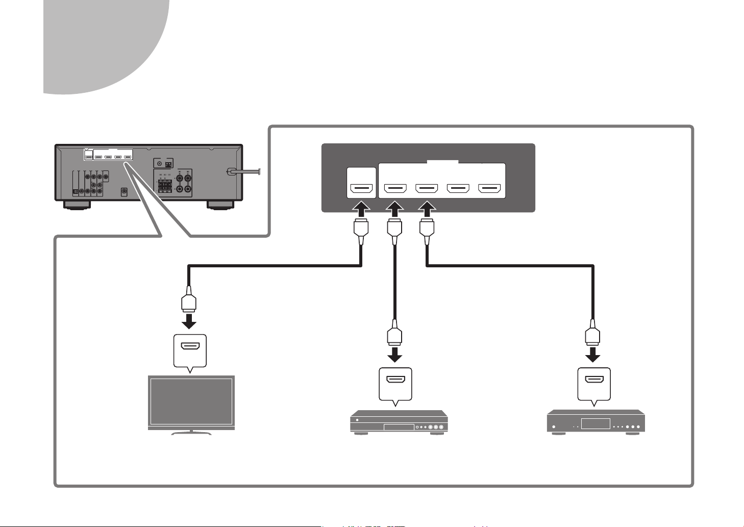
3
HDMI
HDMI HDMI
(BD/DVD)
2
3
1
HDMI
(HDCP2.2)
4
HDCP2.2
ARC
HDMI OUT
HDMI HDMI HDMI
HDMI
HDMI
HDMI
Televisor Reproductor BD/DVD Reproductor digital multimedia
por cable/satélite
Entrada HDMI
Salida HDMI Salida HDMI
Conexión de dispositivos externos
38 Es
Page 39
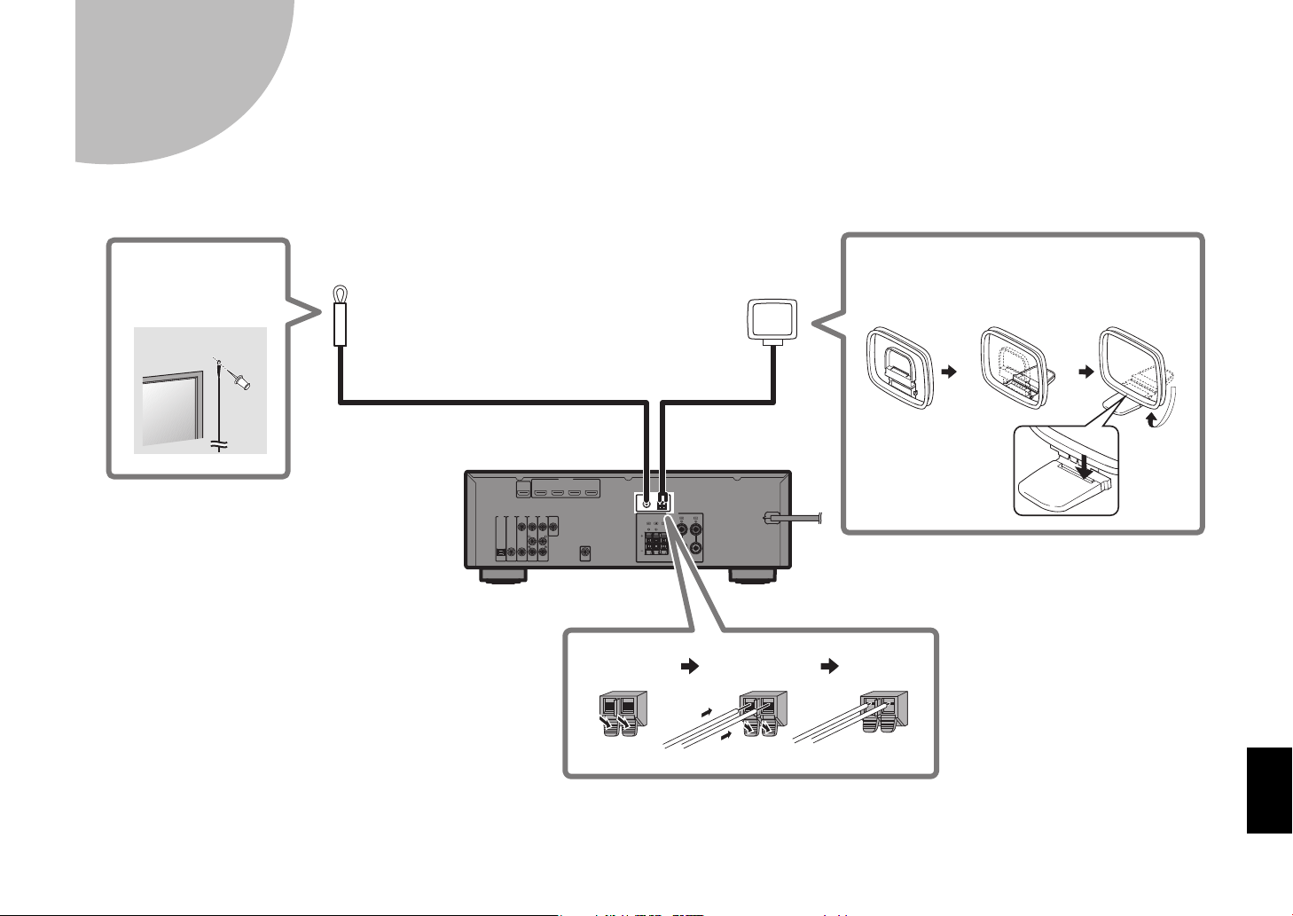
4
Antena de FM (suministrada)
Antena de AM (suministrada)
Mantener
pulsado
Insertar Soltar
Montaje de la antena de AM
Coloque la antena
de AM sobre una
superficie plana.
Fije el extremo de la
antena de FM a la
pared.
Conexión de antenas de FM/AM
Es 39
Page 40

Conectar el cable de alimentación a una toma de
A una toma de CA
VOLTAGE SELECTOR
(Solo modelos generales, de Taiwán y de Brasil)
PROGRAM
STRAIGHT
ENHANCER BASS
BD
DVD
TV
SCENE
RADIO
SLEEP
CD
G
S
T
R
T
E
B
A
SS
BD
T
V
R
ADIO
S
CD
z
5
CA y encender la unidad
Antes de conectar el cable de alimentación
(Solo modelos generales, de Taiwán y de Brasil)
Ajuste la posición del conmutador de VOLTAGE SELECTOR (selector de
tensión) según su tensión local.
Las tensiones son 110–120/220-240 V CA, 50/60 Hz.
1 Conecte el cable de alimentación a una toma de
CA.
2 Pulse z (alimentación del receptor) para encender
la unidad.
LEEP
SCEN
AIGH
NHANCER
O
3 Encienda el televisor y cambie la entrada de TV
para que se muestre el vídeo de la unidad (toma
HDMI OUT).
40 Es
VOLTAGE
SELECTOR
110V120V
220V240V
Page 41

Optimización de los ajustes de los altavoces
12
3
9
54
TUNING
PRESET
MUTE
TUNING
MEMORY
TOP MENU
HOME
POP-UP/MENU
DISPLAYRETURN
SETUP
OPTION
VOLUME
USB
INPUT
ENTER
BLUE
YELLOWGREEN
RED
BLUETOOTH
T
MUTE
U
E
POP-UP/
U
SETUP
O
OPTION
USB
U
BLUE
O
G
BLUEO
O
ENTER
Tenga en cuenta lo siguiente
respecto a la medición YPAO:
• Los tonos de prueba se
emiten con un volumen
elevado y pueden sorprender
o asustar a los niños
pequeños.
• El volumen del tono de
prueba no puede ajustarse.
• Mantenga la sala lo más
silenciosa posible.
• Permanezca en una esquina
de la sala detrás de la
posición de escucha para no
ser un obstáculo entre los
altavoces y el micrófono
YPAO.
• No conecte auriculares.
Altura del oído
Posición de escucha
Micrófono YPAO
Teclas de
cursor
6
automáticamente (YPAO)
La función Yamaha Parametric room Acoustic Optimizer (YPAO) detecta las conexiones de los altavoces, mide las distancias desde la posición de escucha y
optimiza automáticamente los ajustes de los altavoces, como el balance de volumen y los parámetros acústicos, para adecuarlos a la sala.
OLUME
TOP MEN
TUNING
HOM
MEN
MEMO
PRESE
TUNING
Es 41
Page 42

1 Encienda el altavoz de subgraves y ajuste su
VOLUME
CROSSOVER/
HIGH CUT
MIN MAX
MIN MAX
Auto Setup
Start
Exit
Auto Setup
Measurement Finished
Result
3/2/0.1ch
3.0/10.5m
-3.0/+10.0dB
OK : ENTER
volumen a la mitad.
Si se puede ajustar la frecuencia de cruce, póngala al máximo.
2 Coloque el micrófono YPAO en la posición de
escucha y conéctelo a la toma YPAO MIC del panel
delantero.
Aparece la pantalla de abajo en el televisor.
42 Es
Nota
Coloque el micrófono YPAO en la posición de escucha (a la altura de sus oídos).
Se recomienda utilizar un trípode como soporte para el micrófono. Puede utilizar
los tornillos del trípode para estabilizar el micrófono.
3 Pulse ENTER.
La medición comenzará al cabo de 10 segundos.
La medición tarda unos 3 minutos en realizarse.
La pantalla de abajo aparece en el televisor cuando acaba la medición.
Nota
Si aparece algún mensaje de error (como E-1) o de advertencia (como W-2),
consulte “Mensajes de error” o “Mensajes de advertencia” en el capítulo
“Optimización de los ajustes de los altavoces automáticamente (YPAO)” del
Manual de Instrucciones.
4 Compruebe los resultados que se muestran en la
pantalla y pulse ENTER.
5 Utilice las teclas del cursor (e/r) para seleccionar
“SAVE” (Guardar) y pulse ENTER.
6 Desconecte el micrófono YPAO de la unidad.
Con esto finaliza la optimización de los ajustes de los altavoces.
Page 43

Operaciones básicas
MUTE
SETUP
OPTION
FM/AM
VOLUME
PROGRAM
USB
STRAIGHT
ENHANCER BASS
INPUT
BD
DVD
TV
SCENE
RADIO
SLEEP
ENTER
CD
BLUETOOTH
SETUP
O
OPTION
S
P
La unidad dispone de diversos programas de
sonido y decodificadores surround que le permiten
escuchar fuentes de reproducción con su modo de
sonido preferido.
STRAIGHT: Las fuentes de entrada se reproducirán sin
efectos de campo de sonido.
ENHANCER: La música comprimida almacenada en un
dispositivo Bluetooth o dispositivo de almacenamiento
USB se reproducirá con una profundidad y una amplitud
mayores.
BASS: Los graves extra le permiten disfrutar de
sonidos graves mejorados.
PROGRAM (e/r): Pueden seleccionarse programas
de sonido apropiados para películas, música y
reproducción estéreo.
Las fuentes de entrada de la unidad y la
configuración asignadas a las teclas SCENE pueden
seleccionarse con un solo toque (función SCENE).
La unidad se enciende automáticamente cuando está
en modo de espera. Los siguientes ajustes están
asignados a cada una de las teclas SCENE de forma
predeterminada.
Tecla SCENE
Entrada HDMI1 AUDIO1 AUDIO2 TUNER
Programa de
sonido
MOVIE
(Sci-Fi)
STRAIGHT STRAIGHT
STEREO
(5ch
Stereo)
Compressed
Music Enhancer
Off On Off On
Reproducción
mediante
vinculación de
SCENE
On On Off Off
BD
DVD
CD
Ajustar el nivel de volumen
Seleccionar una fuente de entrada
Silenciar la salida de audio
Encender y apagar (espera) la unidad
En este apartado se describen operaciones básicas como la reproducción de discos Blu-ray y DVD, y la sintonización de emisoras de radio. La mayoría de las
operaciones pueden realizarse con el mando a distancia.
Uso del mando a distancia
LEE
TV
RADIO
Es 43
Page 44

Reproducción de BD/DVD
MUTE
ENHANCER
STEREO
TUNED
SLEEP
ECO
CHARGE
ADAPTIVE DRC
VIRTUAL
BD Player
VOL.
OUT
Fuente de entrada Nombre del dispositivo
TUNING
PRESET
MUTE
TUNING
MEMORY
TOP MENU
HOME
POP-UP/MENU
DISPLAYRETURN
SETUP
OPTION
FM/AM
VOLUME
PROGRAM
USB
STRAIGHT
ENHANCER BASS
INPUT
BD
DVD
TV
SCENE
RADIO
SLEEP
ENTER
BLUE
YELLOWGREEN
RED
CD
BLUETOOTH
G
PRESET
G
O
R
O
E
P
SETUP
O
OPTION
O
P
ROGRAM
US
E
S
D
VD
SC
E
O
S
G
RED
C
BLUETO
O
TH
VOLUME
( / )
INPUT
(q/w)
STRAIGHT
TUNIN
P MENU
LEEP
EN
FM/AM
B
HOM
MEM
D
NHANCER
MUTE
OP-UP/MENU
Y
ADI
BLUE
TUNIN
Le recomendamos que reproduzca audio de varios canales (5.1 canales o más) para sentir el sonido surround
producido por la unidad.
S
1 Encienda el reproductor BD/DVD.
2 Pulse INPUT (q/w) varias veces
para seleccionar “HDMI 1”.
Puede mostrarse el nombre del dispositivo
3 Inicie la reproducción en el
reproductor BD/DVD.
4 Pulse STRAIGHT para seleccionar
“STRAIGHT”.
conectado, como “BD player”.
Nota
Cuando está activado el modo “STRAIGHT”
(decodificación directa), cada altavoz produce
directamente la señal de audio de cada canal (sin
procesamiento de campo sonoro).
5 Pulse VOLUME para ajustar el
volumen.
Nota
Si no se oye el sonido o un determinado altavoz no emite
sonido, consulte “Resolución de problemas” en el Manual de
Instrucciones.
44 Es
Page 45

ENHANCER
LINK
ECO
MASTER
OUT
2
-
R
es
Hi
YPAO
VOL.
A-DRC
SLEEP
PART Y
ZONE
A2B3
FPR
SBL SB SBR
FPL
MUTE VIRTUAL
VOL.
SLSWSR
STEREO
TUNED
FM 98.50MHz
TUNING
PRESET
MUTE
TUNING
MEMORY
TOP MENU
HOME
POP-UP/MENU
DISPLAYRETURN
SETUP
OPTION
FM/AM
VOLUME
PROGRAM
USB
STRAIGHT
ENHANCER BASS
INPUT
BD
DVD
TV
SCENE
RADIO
SLEEP
ENTER
BLUE
YELLOWGREEN
RED
CD
BLUETOOTH
MUTE
T
O
U
HO
SETUP
O
OPTION
OLU
G
USB
S
T
R
AIGHT
B
A
SS
U
BD
T
R
ADIO
S
BLUE
O
G
CD
BLUEO
O
FM/AM
TUNING
V
LEEP
SCEN
O
ENHANCER
ME
Escucha de radio FM/AM
1 Pulse FM/AM para seleccionar la
banda.
Se selecciona “TUNER” como fuente de entrada y,
a continuación, se muestra la frecuencia que está
seleccionada.
2 Pulse TUNING varias veces para
ajustar una frecuencia.
Mantenga la tecla pulsada un segundo para buscar
emisoras automáticamente.
“TUNED” se ilumina cuando la unidad está
recibiendo una señal de emisora de radio FM/AM.
“STEREO” se ilumina cuando la unidad está
recibiendo una señal de radio FM estéreo.
Configuración de los pasos de frecuencia (solo
modelos generales, de Asia, de Taiwán y de
Brasil)
En fábrica, la configuración de los pasos de frecuencia se
establece en 50 kHz para FM y 9 kHz para AM.
Según la región o el país donde escuche la radio,
establezca los pasos de frecuencia en 100 kHz para FM y
10 kHz para AM.
1 Ponga la unidad en modo de espera.
2 Mientras mantiene pulsado STRAIGHT en el panel
delantero, pulse z (alimentación).
3 Pulse PROGRAM el el panel delantero varias veces
para seleccionar “TU”.
MASTER
LINK
2
OUT
ECO
-
ResHi
TU••••FM50/AM9
4 Pulse STRAIGHT el el panel delantero para
seleccionar “FM100/AM10”.
5 Pulse z (alimentación) para poner la unidad en
modo de espera y volver a encenderla.
STEREO
SLEEP
ENHANCER
ZONE
TUNED
A2B3
PARTY
A-DRC
VOL.
YPAO
VOL.
MUTE VIRTUAL
FPR
FPL
SR
SW
SL
SBL SB SBR
P MEN
MEMO
PRESET
ME
POP-UP/MENU
Es 45
Page 46

Reproducción de música
RADIO
Unidad USB
TUNING
PRESET
MUTE
TUNING
MEMORY
TOP MENU
HOME
POP-UP/MENU
DISPLAYRETURN
SETUP
OPTION
FM/AM
VOLUME
PROGRAM
USB
STRAIGHT
ENHANCER BASS
INPUT
BD
DVD
TV
SCENE
RADIO
SLEEP
ENTER
BLUE
YELLOWGREEN
RED
CD
BLUETOOTH
G
MUTE
G
T
O
U
HO
SETUP
O
OPTION
FM/
OLU
G
S
T
R
AIGHT
B
A
SS
U
BD
T
R
ADIO
S
BLUE
O
G
CD
USB
BLUETOOTH
ENTER
MEMORY
Reproducción de música
TUNIN
P MEN
LEEP
SCEN
V
ENHANCER
O
AM
ME
PRESET
ME
Teclas de
cursor
POP-UP/MENU
TUNIN
almacenada en un
dispositivo Bluetooth
®
1 Pulse BLUETOOTH para
seleccionar “Bluetooth” como
fuente de entrada.
2 Mantenga pulsado MEMORY más
de 3 segundos.
En el visor delantero aparece “Searching…”.
3 Active la función BLUETOOTH en
su dispositivo y seleccione el
nombre de modelo de la unidad de
la lista de dispositivos BLUETOOTH
de su dispositivo.
Si se requiere clave de acceso, introduzca el
número “0000”.
Cuando se establezca la conexión, se iluminará el
indicador del visor delantero.
4 Seleccione una canción e inicie la
reproducción en el dispositivo
Bluetooth.
Nota
El audio que se reproduce en la unidad puede transmitirse a
auriculares o altavoces Bluetooth inalámbricos (excepto si se
selecciona Bluetooth como la fuente de entrada de la unidad).
Consulte “Reproducción de audio a través de altavoces/
auriculares Bluetooth” en el Manual de Instrucciones para
obtener más información.
almacenada en una unidad
USB
1 Conecte la unidad USB a la toma
USB.
AUX
STRAIGHT
Nota
Conecte la unidad USB directamente a la toma USB. No
utilice un cable alargador.
USB
AUDIO
2 Pulse USB para seleccionar “USB”
como fuente de entrada.
En el televisor se muestra la pantalla de
navegación.
3 Utilice las teclas del cursor para
seleccionar un elemento y pulse
ENTER.
Si hay una canción seleccionada, empieza la
reproducción y se muestra la pantalla de
reproducción.
46 Es
Page 47

Information for Users on Collection and Disposal of Old Equipment and Used Batteries
Information concernant la collecte et le traitement des piles usagées et des déchets
d’équipements électriques et électroniques
These symbols on the products, packaging, and/or accompanying documents mean that used
electrical and electronic products and batteries should not be mixed with general household
waste.
For proper treatment, recovery and recycling of old products and used batteries, please take
them to applicable collection points, in accordance with your national legislation and the
Directives 2002/96/EC and 2006/66/EC.
By disposing of these products and batteries correctly, you will help to save valuable
resources and prevent any potential negative effects on human health and the environment
which could otherwise arise from inappropriate waste handling.
For more information about collection and recycling of old products and batteries, please
contact your local municipality, your waste disposal service or the point of sale where you
purchased the items.
[Information on Disposal in other Countries outside the European Union]
These symbols are only valid in the European Union. If you wish to discard these items,
please contact your local authorities or dealer and ask for the correct method of disposal.
Note for the battery symbol (bottom two symbol examples):
This symbol might be used in combination with a chemical symbol. In this case it complies
with the requirement set by the Directive for the chemical involved.
Les symboles sur les produits, l’emballage et/ou les documents joints signifient que les
produits électriques ou électroniques usagés ainsi que les piles ne doivent pas être mélangés
avec les déchets domestiques habituels.
Pour un traitement, une récupération et un recyclage appropriés des déchets d’équipements
électriques et électroniques et des piles usagées, veuillez les déposer aux points de collecte
prévus à cet effet, conformément à la réglementation nationale et aux Directives 2002/96/EC
et 2006/66/EC.
En vous débarrassant correctement des déchets d’équipements électriques et électroniques et
des piles usagées, vous contribuerez à la sauvegarde de précieuses ressources et à la
prévention de potentiels effets négatifs sur la santé humaine qui pourraient advenir lors d’un
traitement inapproprié des déchets.
Pour plus d’informations à propos de la collecte et du recyclage des déchets d’équipements
électriques et électroniques et des piles usagées, veuillez contacter votre municipalité, votre
service de traitement des déchets ou le point de vente où vous avez acheté les produits.
[Information sur le traitement dans d’autres pays en dehors de l’Union
Européenne]
Ces symboles sont seulement valables dans l’Union Européenne. Si vous souhaitez vous
débarrasser de déchets d’équipements électriques et électroniques ou de piles usagées,
veuillez contacter les autorités locales ou votre fournisseur et demander la méthode de
traitement appropriée.
Note pour le symbole « pile » (les deux symboles du bas) :
Ce symbole peut être utilisé en combinaison avec un symbole chimique. Dans ce cas il
respecte les exigences établies par la Directive pour le produit chimique en question.
Información para usuarios sobre recolección y disposición de equipamiento viejo y
baterías usadas
Estos símbolos en los productos, embalaje, y/o documentación que se acompañe significan
que los productos electrónicos y eléctricos usados y las baterías usadas no deben ser
mezclados con desechos domésticos corrientes.
Para el tratamiento, recuperación y reciclado apropiado de los productos viejos y las baterías
usadas, por favor llévelos a puntos de recolección aplicables, de acuerdo a su legislación
nacional y las directivas 2002/96/EC y 2006/66/EC.
Al disponer de estos productos y baterías correctamente, ayudará a ahorrar recursos valiosos
y a prevenir cualquier potencial efecto negativo sobre la salud humana y el medio ambiente,
el cual podría surgir de un inapropiado manejo de los desechos.
Para más información sobre recolección y reciclado de productos viejos y baterías, por favor
contacte a su municipio local, su servicio de gestión de residuos o el punto de venta en el
cual usted adquirió los artículos.
[Información sobre la disposición en otros países fuera de la Unión Europea]
Estos símbolos sólo son válidos en la Unión Europea. Si desea deshacerse de estos artículos,
por favor contacte a sus autoridades locales y pregunte por el método correcto de
disposición.
Nota sobre el símbolo de la batería (ejemplos de dos símbolos de la parte
inferior)
Este símbolo podría ser utilizado en combinación con un símbolo químico. En este caso el
mismo obedece a un requerimiento dispuesto por la Directiva para el elemento químico
involucrado.
SIMPLIFIED EU DECLARATION OF CONFORMITY
Hereby, Yamaha Music Europe GmbH declares that the radio equipment type
[RX-V383, HTR-3071] is in compliance with Directive 2014/53/EU. The full text of the EU
declaration of conformity is available at the following internet address:
https://europe.yamaha.com/en/support/compliance/doc.html
DECLARATION UE DE CONFORMITE SIMPLIFIEE
Le soussigné, Yamaha Music Europe GmbH, déclare que l'équipement radioélectrique du type
[RX-V383, HTR-3071] est conforme à la directive 2014/53/UE. Le texte complet de la déclaration
UE de conformité est disponible à l'adresse internet suivante:
https://europe.yamaha.com/en/support/compliance/doc.html
DECLARACIÓN UE DE CONFORMIDAD SIMPLIFICADA
Por la presente, Yamaha Music Europe GmbH declara que el tipo de equipo radioeléctrico
[RX-V383, HTR-3071] es conforme con la Directiva 2014/53/UE. El texto completo de la
declaración UE de onformidad está isponible en la dirección Internet siguiente:
https://europe.yamaha.com/en/support/compliance/doc.html
47
Page 48

AVEG1A1102C
Important Notice: Guarantee Information for customers
in EEA* and Switzerland
For detailed guarantee information about this Yamaha product, and Pan-EEA* and
Switzerland warranty service, please either visit the website address below (Printable file is
available at our website) or contact the Yamaha representative office for your country.
* EEA: European Economic Area
Remarque importante: informations de garantie pour
les clients de l’EEE et la Suisse
Pour des informations plus détaillées sur la garantie de ce produit Yamaha et sur le service de
garantie applicable dans l’ensemble de l’EEE ainsi qu’en Suisse, consultez notre site Web à
l’adresse ci-dessous (le fichier imprimable est disponible sur notre site Web) ou contactez
directement Yamaha dans votre pays de résidence. * EEE : Espace Economique Européen
Aviso importante: información sobre la garantía para
los clientes del EEE* y Suiza
Para una información detallada sobre este producto Yamaha y sobre el soporte de garantía
en la zona EEE* y Suiza, visite la dirección web que se incluye más abajo (la version del
archivo para imprimir esta disponible en nuestro sitio web) o póngase en contacto con el
representante de Yamaha en su país. * EEE: Espacio Económico Europeo
http://europe.yamaha.com/warranty/
English
Français
Español
Yamaha Global Site
http://www.yamaha.com/
Yamaha Downloads
http://download.yamaha.com/
Manual Development Group
© 2017 Yamaha Corporation
Published 05/2017 KS-B0
Printed in Malaysia
ZY76570
 Loading...