


Owner’s Manual
AV Receiver English for Asia*, Africa, Oceania and
Latin America
*Except for China

CONTENTS
INTRODUCTION
Features and capabilities...................................................3
About this manual.............................................................4
Supplied accessories.........................................................4
Part names and functions..................................................5
Front panel........................................................................5
Rear panel..................................... ................................. ...6
Front panel display...........................................................7
Remote control .................................................................8
CONNECTIONS
Connecting speakers..........................................................9
Speaker channels and functions........................................9
Speaker layout................................................................10
Connecting speakers.......................................................10
Connecting external devices............................................12
Cable plugs and jacks.....................................................12
Connecting a TV monitor...............................................13
Connecting BD/DVD players and other devices............15
Connecting video cameras and portable audio players ..19
Transmitting input A/V to external devices....................19
Connecting the FM/AM antennas..................................20
Set up the speaker parameters automatically
(YPAO)..............................................................................21
PLAYBACK
Basic playback procedure...............................................25
Adjusting high/low-frequency sound (Tone control) .....25
Changing input settings wit h a single key
(SCENE function)............................................................26
Registering input sources/sound field program..............26
Enjoying sound field programs.......................................26
Selecting sound field programs and sound decoders......26
Sound field programs .....................................................28
FM/AM tuning............................................................ .....30
Selecting a frequency for reception (Normal tuning).....30
Registering and recalling a frequency (Preset tuning)...31
Clearing preset stations ..................................................33
Playing back tunes from your iPod™/iPhone™...........35
Connecting the Yamaha iPod universal dock.................35
Controlling an iPod/iPhone............................................35
Playing back tunes from Bluetooth™ components....... 37
Connecting a Yamaha Bluetooth wireless
audio receiver................................................................. 37
Pairing Bluetooth™ components ...................................37
Using Bluetooth™ components.....................................38
SETUP
Configuring the settings specific for each input source
(Option menu)..................................................................39
Option menu display and setup......................................39
Option menu items.........................................................39
Setting various functions (Setup menu).........................42
Setup menu display and settings ....................................42
Setup menu items...........................................................42
Manages settings for speakers........................................43
Setting the audio output function of this unit.................46
Setting HDMI functions.................................................47
Making the receiver easier to use...................................49
Setting sound field program parameters.........................50
Prohibiting setting changes ............................................50
Setting sound field program parameters.......................51
Setting sound field parameters.......................................51
Controlling other components with the
remote control..................................................................53
Keys connecting external components...........................53
Default remote control code settings..............................53
Registering remote control codes for external component
operations.......................................................................54
Resetting all remote control codes.................................55
Extended functionality that can be configured
as needed (Advanced Setup menu) ................................ 56
Displaying/Setting the Advanced Setup menu............... 56
Avoiding crossing remote control signals when using
multiple Yamaha receivers............................................. 57
Changing FM/AM frequency steps (Asia and General
models only)...................................................................57
Initializing various settings for this unit ........................57
Using the HDMI Control function................................. 58
APPENDIX
Troubleshooting............................................................... 61
General...........................................................................61
HDMI™......................................................................... 64
Tuner (FM/AM)............................................................. 64
Remote control...............................................................65
iPod™/iPhone™............................................................66
Bluetooth™....................................................................66
Glossary............................................................................ 67
Audio information.......................................................... 67
Sound field program information................................... 68
Video information.......................................................... 68
Information on HDMI™................................................. 69
About trademarks ........................................................... 69
Specifications.................................................................... 70
Index................................................................................. 71
En 2

INTRODUCTION
Features and capabilities
■ Built-in high-quality, high-power 5-channel amplifier
■ 1-button input/sound field program switching (SCENE function).......................26
■ Speaker connections for 2- to 5.1-channel configurations
– Speaker channels and functions .................................................................................................................9
– Speaker layout..........................................................................................................................................10
– Speaker cable connection.........................................................................................................................10
– Subwoofer cable connection................................................................................................. ...................11
■ Acoustic parameter adjustment to match your speakers and listening
environment
– Automatic settings for speaker acoustic parameters
(YPAO - Yamaha Parametric room Acoustic Optimizer)........................................................................21
– Specifying the settings for each speaker..................................................................................................43
– Volume control for each speaker..............................................................................................................44
– Speaker distance settings .........................................................................................................................44
– Sound quality control with the equalizer <Graphic Equalizer> ..............................................................45
– Test tone speaker adjustment...................................................................................................................45
– Bass and treble level adjustment <Tone Control> ...................................................................................25
■ External device connection and playback
– Cables and input/output jacks for this unit ............................................................................... .. .............12
– TV connection..........................................................................................................................................13
– TV audio playback through this receiver.................................................................................................14
– Connections for BD/DVD players (recorders) and other devices............................................................15
– Audio signal output to the TV connected via the HDMI jack.................................................................48
– Correction of lag between audio and vid e o sig n a ls <Li psync>. .. ............................................................46
– External audio and video recorder connections.......................................................................................19
– HDMI/AV video input combining other audio input...............................................................................40
– Front panel external device connections (for video cameras, portable music players, etc.)....................19
– Protective cover for front panel jacks ........................................................................................................4
– Changing the input source names <Input Rename>.................................................. ..............................49
– Configuring the settings specific for each input source <Option menu> ................................................39
– Playback from external devices ...............................................................................................................25
– Playback from an iPod/iPhone (iPod/iPhone and components sold separately) .....................................35
– Playback from a Bluetooth component (Bluetooth and components sold separately)............................37
■ Multi-channel, multi-format playback
– Sound field effect selection......................................................................................................................26
– Playback without sound field effects .............................. .........................................................................27
– Stereo playback........................................................................................................................................27
– Sound field effect configuration ..............................................................................................................51
– Compressed-music playback ...................................................................................................................26
■ Front panel information display
– Front panel display information switching................................................................................................7
– Front panel display brightness adjustment <Dimmer>............................................................................50
– Digital video/audio signal information display <Signal Info> ................................................................40
■ Volume/sound quality adjustment functions
– Easy listening at low volumes <Adaptive DRC> ....................................................................................46
– Maximum volume settings............... ................................. .......................................................................47
– Startup volume settings..... ... .. .. ................................................................................................................47
– Adjusting volume between input sources <Volume Trim>.....................................................................40
■ Remote control operation
– Remote control names and functions.........................................................................................................8
– Insert batteries into the remote control ......................................................................................................4
– External device operation with this unit’s remote control.......................................................................53
– Multiple Yamaha receiver operation without signal interference <Remote ID Switching>....................57
■ Other features
– Standby mode after prolonged non-operation <Auto Power Down function>.................. .. ....................50
– Standby mode after a specific amount of time <Sleep timer>................................................. .... ..............8
– To charge the iPod/iPhone when this unit is in standby mode <iPod Standby Charge> .........................36
– Initializing various settings for this unit ..................................................................................................57
– Prohibiting setting changes <Memory Guard>........................................................................................50
■ FM/AM Tuner
– FM/AM broadcast listening ............................ ... .. ................................................................. ...................30
– Simple preset tuning ........ ................................................................. .......................................................31
– Changing FM/AM frequency steps initializing various settings for this unit..........................................30
En 3
INTRODUCTION
Features and capabilities
About this manual
• This manual is printed prior to production. Design and
specifications are subject to change in part as a result of
improvements, etc. In case of differences between the manual and
product, the product has priority.
• “
dHDMI1” (example) indicates the name of the parts on the
remote control. Refer to the “Remote control” (☞
information about each position of the parts.
• J
1 indicates that the reference is in the footnote. Refer to the
corresponding numbers on the bottom of the page.
• ☞
indicates the page describing the related information.
• Click on the “ ” at the bottom of the page to display the
corresponding page in “Part names and functions.”
Front panel
Rear panel
Front panel display
Remote control
p. 8) for the
Supplied accessories
Check that you received all of the following parts.
• Remote control
• Batteries (AAA, R03, UM-4) x 2
• YPAO microphone
• AM loop antenna
• Indoor FM antenna
• VIDEO AUX input cover
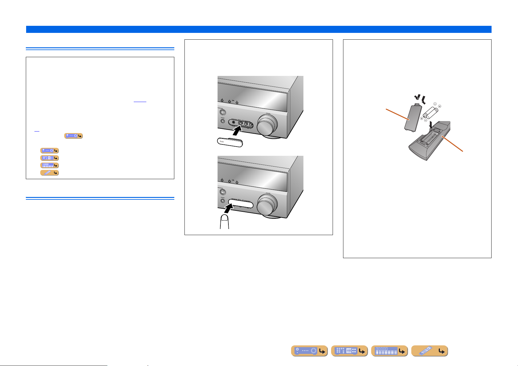
■ Attaching the VIDEO AUX input cover (included)
To protect against dust, attach the supplied VIDEO AUX input
cover to the VIDEO AUX jacks when you do not use the jacks.
T o remove the cover, push the left section of it.
Attach the cover
PUSH
Remove the cover
■ Installing batteries in the remote control
When inserting batteries in the remote control, remove the
battery compartment cover from the reverse side of the remote
control, and insert two AAA batteries into the battery
compartment so that they match with the polarity marki ngs (+
and -).
Battery compartment
cover
a
c
b
Battery compartment
Replace the batteries with new ones if the following symptoms
become evident:
• The remote control can only be operated within a narrow range.
•
bTRANSMIT does not light up, or only lights dimly.
NOTE
If there are remote control codes for external components
registered to the remote control, remo ving the batteries f or more
than two minutes, or leaving exhausted batteries in the remote
control, the remote control codes may be cleared. If this should
occur, replace the batteries with new ones, and set the remote
control codes.
En 4
Part names and functions
INTRODUCTION
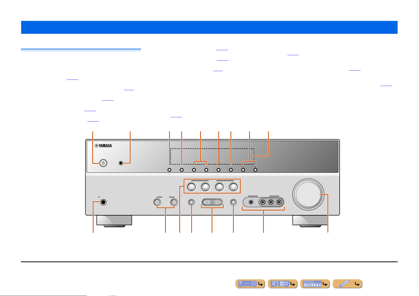
Front panel
a A (Power)
Switches this unit between on and standby modes.
b YPAO MIC jack
Connect the supplied YPAO microphone and adjust the speaker
balance automatically (☞
c INFO
Changes the information shown on the front panel display (☞
d MEMORY
Registers FM/AM stations as preset stations (☞
e PRESET j / i
Selects an FM/AM preset station (☞
f FM
Sets the FM/AM tuner band to FM (☞
p. 21).
p. 32). J1
p. 33). J1
p. 30). J1
a
YPAO MIC
p. 7).
b
g AM
Sets the FM/AM tuner band to AM (☞
p. 30). J1
h TUNING jj / ii
Changes FM/AM tuner frequencies (☞
p. 30). J1
i Front panel display
Displays information on this unit (☞
p. 7).
j PHONES jack
For plugging headphones in. Sound effects applied during playback
can also be heard through the headphones.
k INPUT l / h
Selects an input source from which to playback. Press either the left or
right key repeatedly to cycle through the input sources in order.
l SCENE
Switches the input source and the sound field program with a single
button (☞
switch on the unit.
p. 26). Press this key when this unit is in standby mode to
c fe gd h
MEMORY
INFO
PRESET
BD
DVD
FM AM
SCENE
TV
CD
RADIO
TUNING
m TONE CONTROL
Adjusts high-frequency/low-frequenc y output of speakers/headphones
(☞
n PROGRAM l / h
Switches between the sound field effect (sound f ield program) you are
using and the surround sound decoder (☞
or right key repeatedly to cycle through the input sources in order.
o STRAIGHT
Changes a sound field program to straight decoding mode (☞
p VIDEO AUX jacks
For connecting video cameras, game consoles, and portable music
players to this unit temporarily.
Attach the supplied VIDEO AUX input cover when not using this
jack.
q VOLUME
Adjusts the volume level.
i
p. 25).
p. 26). Press either the left
p. 27).
VOLUME
J
1 : Usable when you have selected tuner input.
SILENT
PHONES
CINEMA
AUX
PORTABLE
VIDEO
VIDEO
p
AUDIO
LR
TONE
INPUT
CONTROL
m ok n
lj q
PROGRAM
STRAIGHT
En 5
Rear panel
GND
V
O
P
B
O
(TV)
AV 1
AV 2
AV 3
AV 4
AV 5
AUDIO 1
AUDIO 2
CO
L
(
C
)
CO
L
O
L
V
O
SURROU
(
BD/
)
3
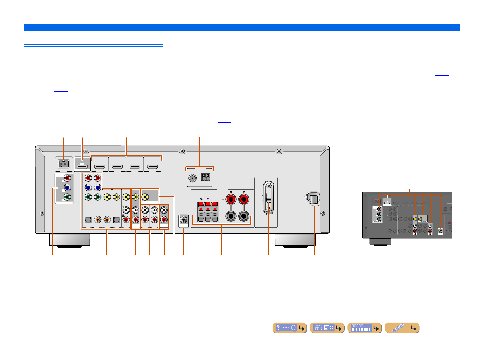
a DOCK jack
For connecting an optional Yamah a iPod universal dock (such as
YDS-12) (☞
p. 37).
(☞
b HDMI OUT jack
For connecting an HDMI - compatible TV to output audio/video
signals to (☞
c HDMI1-4 jacks
For connecting external components equipped with HDMIcompatible outputs to receive audio/video signals from (☞
d ANTENNA jacks
For connecting AM and FM antennas (☞
p. 35) or Bluetooth wireless audio receiver (YBA-10)
p. 13).
p. 20).
p. 15).
e COMPONENT VIDEO jacks
For connecting TV that are compatible with component video signals,
using three cables to output video signal (☞
p. 13).
f AV1-5 jacks
For connecting to external devices equipped with audio/video outputs
so that this unit can receive audio/video signals (☞
p. 16, p. 17).
g AV OUT jacks
For outputting audio/video signals received when analog inputs (AV35 or AUDIO1-2) are selected (☞
p. 19).
h AUDIO1-2 jacks
For connecting to external components equipped with analog audio
outputs to input sound into this unit (☞
p. 18).
i MONITOR OUT jack
For connecting a TV capable of receiving video input, and outputting
video signals to it (☞
p. 14).
INTRODUCTION
Part names and functions
j AUDIO OUT jacks
For outputting audio signals received when analog inputs such as the
AV5 or AUDIO1-2 jacks are selected (☞
k SUBWOOFER jack
For connecting a subwoofer with a built-in amplifier (☞
l SPEAKER terminals
For connecting the front, center, and surround speakers (☞
m VOLTAGE SELECTOR
(Asia and General models only)
Select the switch position according to your local voltage (Refer to
Quick Reference Guide).
n Power cord
For connecting this unit to an AC wall outlet.
p. 19).
p. 11).
p. 11).
HDMI 2 HDMI 3
VIDEO
OPTICAL
(CD)
AV 3
AV 4
c
HDMI 4
MONITOR OUT
(
TV
AV
)
OUT
AV 5
AUDIO 1
AUDIO 2
AUDIO
OUT
a
DOCK
COMPONENT
VIDEO
MONITOR OUT
e j
b
ARC
(
)
BD/DVD
OUT
HDMI
P
R
P
B
Y
P
R
P
B
Y
COMPONENT
VIDEO
OPTICAL
AV 1
COAXIAL
AV 2
HDMI 1
COAXIAL
fg khi l
SUBWOOFER
FM
d
ANTENNA
SURROUND
Distinguishing the input and output jacks
The area around the audio/video output jacks is
marked in white to prevent connection errors.
GND
AM
SPEAKERS
CENTER
FRONT
110V120V
220V240V
VOLTAGE
SELECTOR
Use these jacks to output audio/video signals
to a TV or other external component.
Output jacks
ARC
DVD
OUT
HDMI
COMPONENT
VIDEO
DOCK
P
R
P
B
Y
COMPONENT
HDMI 2HDMI
HDMI 1
IDE
IDE
AXIA
AXIA
PTICA
PTICAL
D
SUBWOOFER
nm
En 6
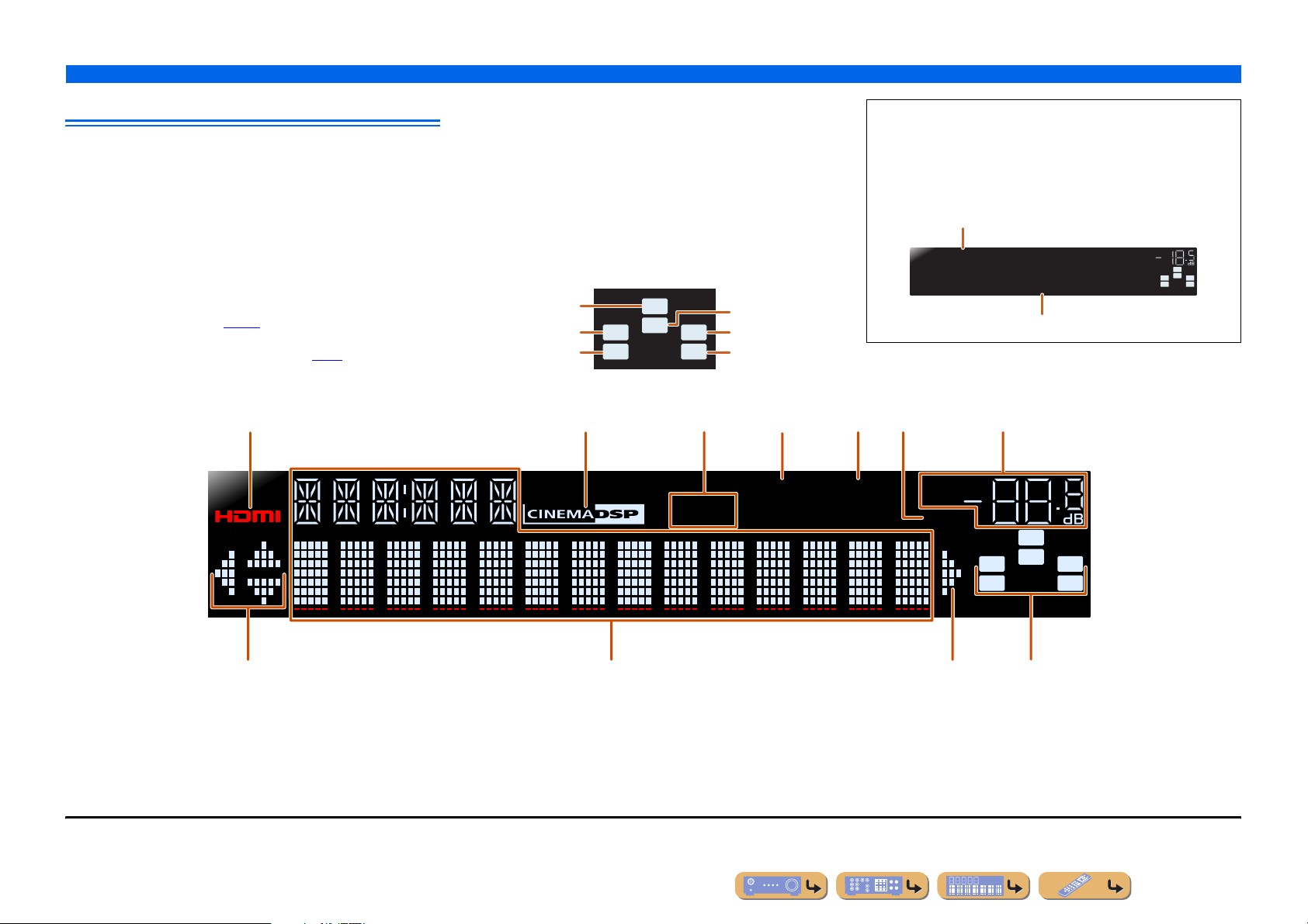
Front panel display
a HDMI indicator
Lights up when HDMI signals are input at the selected HDMI input
source.
b CINEMA DSP indicator
Lights up when a sound field effect that uses CINEMA DSP
technology is selected.
c Tuner indicator
Lights up when receiving an FM/AM broadcast.
d iPod CHARGE indicator
Lights up when an iPod/iPhone is connected through an optional
Yamaha iPod universal do ck (such as YDS-12), and the iPod Standb y
Charge function is active (☞
e SLEEP indicator
Lights up when the sleep timer is activated (☞
p. 36).
p. 8).
abcedgf
f MUTE indicator
Flashes when audio is muted.
g VOLUME indicator
Displays the current volume level.
h Cursor indicators
Light up if corresponding cursors on the remote control are available
for operations.
i Multi information display
Displays a range of information on menu items and settings.
j Speaker indicators
Indicate speaker terminals from which signals are output.
Subwoofer
Front speaker L
Surround speaker L
SW
C
LR
SL SR
Center speaker
Front speaker R
Surround speaker R
INTRODUCTION
Part names and functions
■ Changing the front panel display
The front panel can display sound field programs and surround
decoder names as well as the active input source.
Press fINFO repeatedly to cycle through input source →
sound field program → surround decoder in order. J1
Input source name
HDMI1
STRAIGHT
Sound field program (DSP program)
VOL.
SW
C
L
SL SR
R
hi jh
J
1 : While selecting a tuner input, the FM/AM frequency is displayed instead of the input source.
STEREO
TUNED
iPod
CHARGE
SLEEP
VOL.
MUTE
SW
C
LR
SL SR
En 7
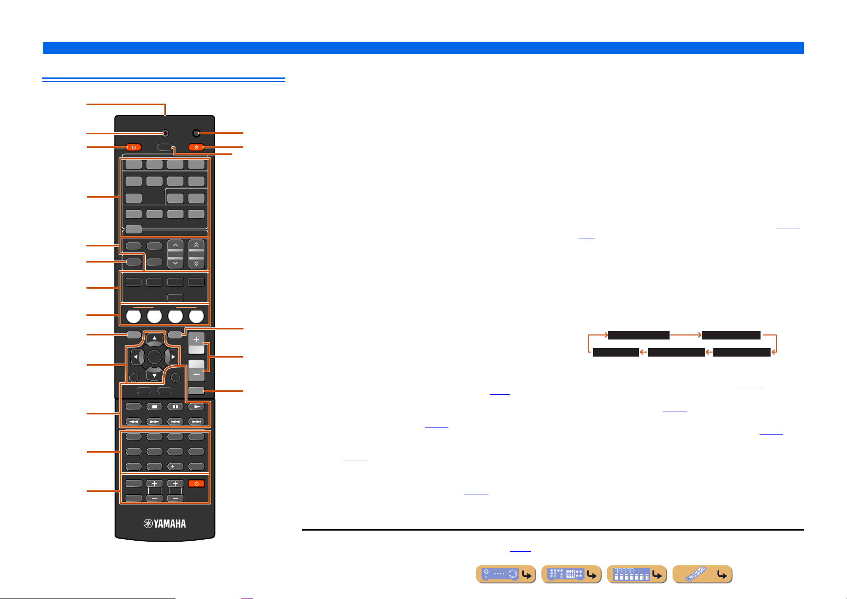
Remote control
a
b
c
d
e
f
g
h
i
j
k
l
m
TRANSMIT
SOURCE
HDMI
1234
1234
V-AUX
TUNER
FM
AM
INFO
MEMORY
MOVIE MUSIC
SCENE
BD
TV
DVD
SETUP
ENTER
RETURN
TOP
MENU
REC
1234
90
INPUT
TV VOL TV CH
MUTE
SLEEP
AV
ENHANCER
STRAIGHT
TV
AUDIO
125
PRESET
STEREO
CD
OPTION
DISPLAY
POP-UP
MENU
7 856
10
RECEIVER
SUR. DECODE
VOLUM E
CODE SET
DOCK[ A ] [ B ]
TUNING
RADIO
MUTE
ENT
p
n
o
q
r
s
a Remote control signal transmitter
Transmits infrared signals.
b TRANSMIT
Lights up when a signal is output from the remote control.
c SOURCE A (SOURCE Power)
Switches an external component on and off.
d Input selector
Select an input source on this unit from which to playback.
HDMI1-4 HDMI1-4 jacks
AV1-5 AV1-5 jacks
AUDIO1-2 AUDIO1-2 jacks
V-AUX Front panel VIDEO AUX jacks
[A]/[B] Changes the external com ponent you operating
with the kExternal component operation
keys without changing inputs. J1
DOCK A Yamaha iPod universal dock or Bluetooth
wireless audio receiver connected to the DOCK
jack.
TUNER FM/AM tuner
e Tuner keys
Operates the FM/AM tuner. These keys are used when using the tuner
input.
FM Sets the FM/AM tuner band to FM.
AM Sets the FM/AM tuner band to AM.
MEMORY Presets radio stations.
PRESET F / G Selects a preset station.
TUNING H / I Changes tuning frequencies.
f INFO
Cycles the information displayed on the front panel display (the name
of the currently selected input source, the sound field program, the
surround decoder, the FM/AM tuner frequency, etc.)(☞
p. 7).
g Sound selection keys
Switch between the sound field effect (sound field program) you are
using and the surround decoder (☞
p. 26).
h SCENE
Switches the input source and the sound field program with a single
button (☞
p. 26). Press this key when this unit is in standby mode to
switch on the unit.
i SETUP
Displays a detailed Setup menu for this unit (☞
p. 42).
INTRODUCTION
Part names and functions
j Cursor B / C / D / E, ENTER, RETURN
Cursor B / C / D / E Select menu items and change settings when
ENTER Confirms a selected it em.
RETURN Returns to the previous screen when setting
k External component operation keys
Operate recording, playback, and menu displays etc. for external
components. J1
l Numeric keys
Enter numbers.
m TV control keys
Operate a monitor such as a TV.
n CODE SET
Sets remote control codes for external component operations (☞
).
p. 57
o RECEIVER A (RECEIVER Power)
Switches this unit between on and standby modes.
p SLEEP
Sets this unit to place itself in standby mode automatically after a
specified period of time has elapsed (sleep timer). Press this key
repeatedly to set the time for the sleep timer function. The front panel
display indicator lights up when the sleep timer is activated.
Sleep 120min. Sleep 90min.
q OPTION
Displays the Option menu for each input source (☞
r VOLUME +/-
Adjusts the volume level (☞
s MUTE
Turns the mute function of the so und output on and off (☞
settings menus, etc are displayed.
menus are displayed, or ends the menu display .
Sleep 60min.Sleep 30min.Sleep Off
p. 39).
p. 25).
p. 53,
p. 25).
JJ
1 : You can use separate kExternal component operation keys for each input source to operate registered components. Remote control codes must be registered for
each input in advance if you wish to operate external components (☞
p. 53).
En 8
CONNECTIONS
Connecting speakers
This unit uses acoustic field effects and sound decoders to bring you the impact of a real movie theater or concert hall. These effects will be brought to you with ideal speaker positioning and
connections in your listening environment.
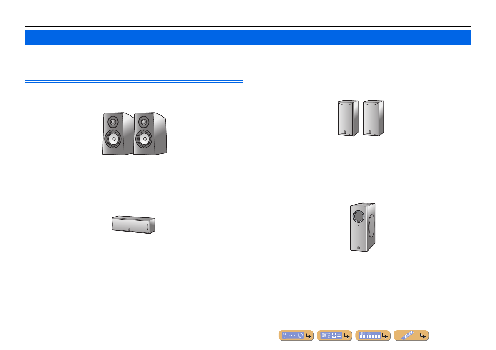
■
Speaker channels and functions
■
Front left and right speakers
The front speakers are used for the front channel sounds (stereo sound) and effect sou nds.
Ex.
Front speaker layout:
Place these speakers at an equal distance from the ideal listening position in the front of the room.
When using a projector screen, the appropriate top positions of the speakers are about 1/4 of the screen
from the bottom.
■
Center speaker
The center speaker is for the center channel sounds (dialog, vocals, etc.).
Surround left and right speakers
The surround speakers are for effect and vocal sounds with the 5.1-channel speakers providing reararea sounds.
Ex.
Surround speaker layout:
Place the speakers at the rear of the room on the left and right sides facing the listening position. They
should be placed between 60 degrees and 80 degrees from the listening position and with the speaker
tops at a height of 1.5 – 1.8 m from the floor.
■
Subwoofer
The subwoofer speaker is used for bass sounds and low-frequency effect (LFE) sounds included in
Dolby Digital and DTS. Use a subwoofer that is equipped with an internal amplifier.
Ex.
Center speaker layout:
Place it halfway between the left and right speakers. When using a TV, place the spea ker j us t above or
just under the center of the TV with the front surfaces of the TV and the speaker aligned.
When using a screen, place it just under the center of the screen.
Ex.
Subwoofer speaker layout:
Place it exterior to the front left and right speakers facing slightly inward to reduce echoes from the
wall.
En 9

CONNECTIONS
Connecting speakers
Speaker layout
5.1-channel speaker layout (5 speakers + subwoofer)
Front speaker R
Front speaker L
Center speaker
60q
80q
60q
80q
Subwoofer
Surround
speaker R
Connecting speakers
Connect your speakers to their respective terminals on the rear panel.
Front speaker
Surround speaker
RL
DMI 4
R OUT
AUDIO
OUT
AUDIO 2
SUBWOOFER
ANTENNA
FM
GND
AM
SPEAKERS
CENTER
SURROUND
RL
FRONT
Surround speaker L
• Connect at least two speakers (front left and right).
• If you cannot connect all fiv e speakers, give priority to the surround speakers.
• The surround speakers should be placed between 60 degrees and 80 degree s from the listenin g position.
■ CRT monitors
W e recommend that you use magnetically shielded speakers to avoid video distortion, especially for
the front and center speakers near the screen.
If your screen still gets interference from magnetically shie lded speakers, move the speakers farther
away from your TV.
Subwoofer Center speaker
CAUTION
• Remove the AC power cord of this unit from the power outlet before connecting the speakers.
• Generally speaker cables consist of two parallel insulated cables. One of these cables is a different
color, or has a line running along it, to indicate different polarity. Insert the different colored (or lined)
cable into the “+” (positive, red) terminal on this unit and the speakers, and the other cable into the “-”
(minus, black) terminal.
• Be careful that the core of the speaker cable does no t touch an ything or come into contact with the metal
areas of this unit. This may damage this unit or the speakers. If the speaker cables short circuit,
“CHECK SP WIRES!” will appear on the front panel display when this unit is switched on.
En 10
■
FRONT
KERS
2
4
FRONT
KERS
CENTER
SURROUND
SPEAKE
2
3
1
Connecting front speakers
CONNECTIONS
Connecting speakers
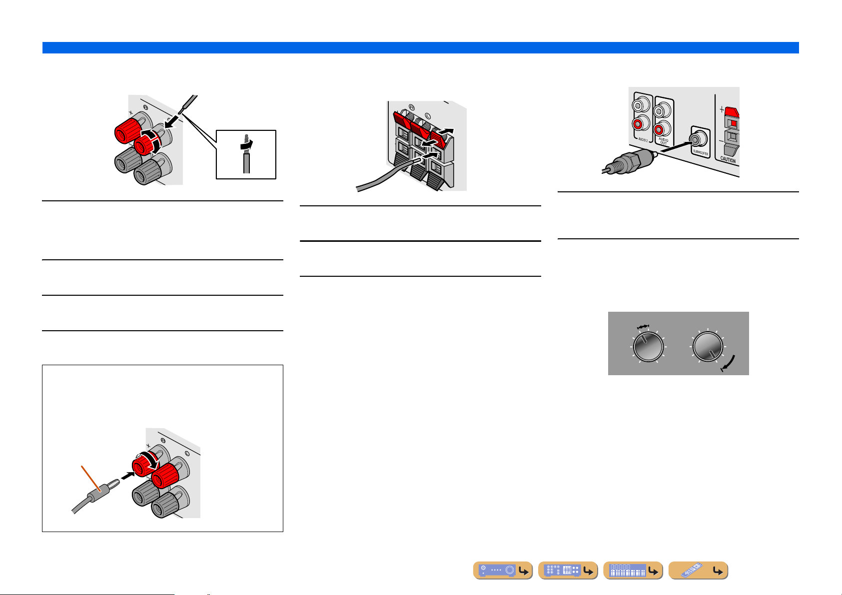
■
Connecting center speakers / surround
speakers
3
■
Connecting the subwoofer
2
1
4
Remove approximately 10mm of insulation from the
1
ends of the speaker cables, and twist the bare wires
of the cables together firmly so that they will not
cause short circuits.
Loosen the speaker terminals.
2
Insert the bare wire of the speaker cable into the gap
on the side of the terminal.
3
Tighten the terminal.
4
Connecting the banana plug (Except U.K., Europe,
Asia and Korea models)
Tighten the knob, and then insert the banana plug into the end of
the terminal.
1
3
2
Press the tab on the speaker terminal down.
1
Insert the speaker cable end into the terminal.
2
Lift the tab to fix the speaker cable in place.
3
Connect the subwoofer input jack to the
1
SUBWOOFER jack on this unit with an audio pin
cable.
Set the subwoofer volume as follows.
2
Volume: Set to approximately half volume (or slightly less than
half).
Crossover frequency (if available): Set to maximum.
CROSSOVER/
VOLUME
MIN MAX
Subwoofer examples
HIGH CUT
MIN MAX
Banana plug
En 11
Connecting external devices
Cable plugs and jacks
■
Audio jacks
CONNECTIONS
The main unit is equipped with the following input/output jacks. Use jacks and cables appropriate for
components that you are going to connect.
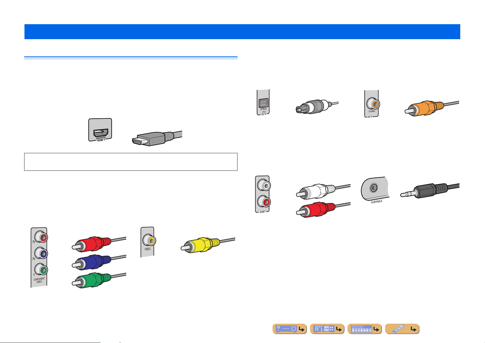
■
Audio/Video jacks
HDMI jacks
Digital video and digital sound are transmitted through a single jack.
Only use an HDMI cable.
HDMI cable
• Use a 19-pin HDMI cable with the HDMI logo.
• We recommend using a cable less than 5.0 m long to prevent signal quality deg rad ation.
■
Analog video jacks
COMPONENT VIDEO jacks
The signal is separated into three components:
luminance (Y), chrominance blue (P
chrominance red (P
Use component video pin cables with three plugs.
R).
Component video pin cable
B), and
VIDEO jack
This jack transmits conventional analog video
signals.
Use video pin cables.
Video pin cable
OPTICAL jacks
These jacks transmit optical digital audio signals.
Use fiber-op tic cables for optical digital audio
signals.
Digital audio fiber-optic cable
AUDIO jacks
These jacks transmit conventional analog audio
signals.
Use stereo pin cables, connecting the red plug to
the red R jack, and the white plug to the white L
jack.
Stereo audio pin cable
COAXIAL jacks
These jacks transmit coaxial digital audio signals.
Use pin cables for digital audio signals.
Digital audio pin cable
PORTABLE jack
This jack transmits conventional analog audio
signals.
Use a stereo mini-plug cable when connecting.
Stereo mini-plug cable
En 12
Connecting a TV monitor
V
P
R
V
O
HDMI 1
(
B
D
)
H
C
T
V
O
P
R
O
L
(
)
AV 1
AV 2
AV 3
AV 4
AV 5
AUDIO 1
AUDIO 2
CO
L
(
C
)
CO
O
L
V
O
HDMI 1
(
B
D
3
COMPO
T
V
O
MO
OUT
P
R
Y
OUT
T
O
OUT
V
O
R
O
L
(
)
AV 1
AV 2
AV 3
AV 4
AV 5
AUDIO 1
AUDIO 2
CO
L
(
C
)
CO
O
V
O
HDMI 1
(
D
)
H
3
I
OU
MO
OUT
O
A
O
OU
D
A
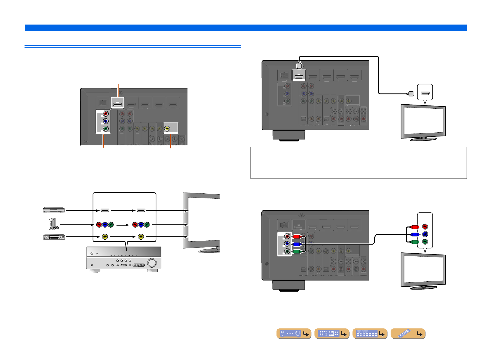
This unit is equipped with the following three types of output jack for connection to a TV.
HDMI OUT, COMPONENT VIDEO or VIDEO. Select the proper connection according to the input
signal format supported by your TV.
HDMI OUT jack
ARC
D/DV
OUT
HDMI
DOCK
COMPONENT
VIDEO
MONITOR OUT
P
R
P
B
Y
COMPONENT
IDE
IDEO
DMI 3
MONITOR OUT
■
Connecting an HDMI video monitor
Connect the HDMI cable to the HDMI OUT jack.
HDMI
ARC
)
D/DV
OUT
HDMI
DOCK
NEN
IDE
NITOR
OMPONEN
IDE
PTICA
IDE
AXIAL
AXIA
D
HDMI
MONITOR
PTICA
TV
OU
CONNECTIONS
Connecting external devices
HDMI input
HDMI
HDMI
TV
AUDI
COMPONENT VIDEO jacks
(MONITOR OUT)
VIDEO jack
(MONITOR OUT)
Video signals input from a particular type of jack(s) are output from the same type of jack(s).
For example, these three output devices must be connected to the monitor by matching input/output
jacks and cables, and then you must change the TV’s input mode to the proper setting.
Input Output
HDMI
COMPONENT
VIDEO
VIDEO
HDMI
COMPONENT
VIDEO
VIDEO
TV
HDMI input
Component
video input
Video input
• Use a 19-pin HDMI cable with the HDMI logo.
• We recommend using a cable less than 5.0 m long to prevent signal quality degradation.
• When using a TV that supports Audio Return Channel function, audio/video signals can be transmitted
mutually between the unit and TV with a single HDMI cable (☞
■
Connecting a component video monitor
p. 60).
Connect the component video cable to the COMPONENT VIDEO (MONITOR OUT) jacks.
Component video input
COMPONENT
TV
VIDEO
P
R
P
B
Y
COMPONENT
VIDEO
MONITOR OUT
RC
BD/DV
T
HDM
OCK
P
R
P
R
P
P
B
P
B
Y
Y
COMPONENT
IDE
IDE
AXIAL
AXIA
PTICA
D
DMI
NITOR
PTICAL
TV
UT
UDI
T
En 13
■
V
O
R
O
L
(
)
AV 1
AV 2
AV 3
AV 4
AV 5
AUDIO 1
AUDIO 2
CO
L
(
C
)
CO
O
V
O
HDMI 1
(
D
)
H
3
COMPO
T
V
OUT
P
R
Y
I
OU
O
A
O
OU
D
ARC
COMPO
T
O
P
B
O
(
BD/
)
3
HDMI 4
C
O
T
HDMI
T
MO
T
AV
O
AUDIO
OUT
DOCK
Y
P
B
C
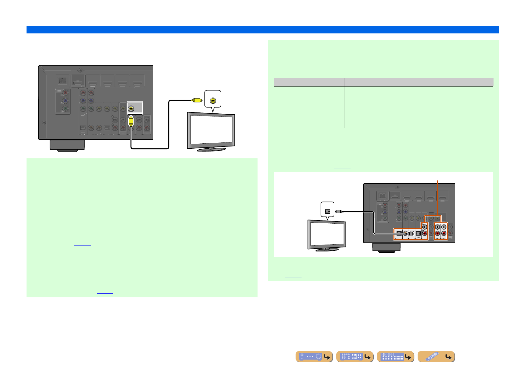
Connecting a video monitor
Connect the video pin cable to the VIDEO (MONITOR OUT) jack.
CONNECTIONS
Connecting external devices
When using other TVs
T o tr ansmit soun d from the TV to this unit, co nnect its AV1-5 or AUDIO1-2 jacks to the TV’s audio
output jacks.
Depending on the connection on TV, connect the TV’s audio output to the AV1-5 or AUDIO1-2.
BD/DV
T
HDM
OCK
NEN
IDEO
MONITOR
■
Listening to TV audio
P
COMPONENT
IDE
PTICA
AXIA
DMI
IDE
MONITOR OUT
V
AXIAL
PTICAL
D
TV
UT
UDI
T
Video input
V
TV
VIDEO
To transmit sound from the TV to this unit, connect as followings according to the TV:
When using a TV that supports the Audio Return Channel function and HDMI
Control function
When your TV supports both HDMI Control (Ex. Panasonic VIERA Link) and Audio Return
Channel functions, audio/video output from the unit to the TV and audio output from the TV to the
unit are possible using a single HDMI cable.
The input source is switched automatically to match operations carried out on the TV, and that
makes TV sound control easier to use.
For the connections and settings, refer to “Single HDMI cable input to TV audio with Audio Return
Channel function” (☞
p. 60).
When using a TV that supports the HDMI Control functions
When using a TV that supports HDMI Control functions (Ex. Panasonic VIERA Link), if HDMI
Control functions are enabled on the unit, then input source can be switched automatically to match
operations carried out on the TV.
For the connections and settings, refer to “Switching the input source on this unit automatically
when listening to TV audio” (☞
p. 59).
TV audio output Connection
Optical digital audio output Connect to the OPTICAL jack of the AV1 or AV4 with a digital audio pin
cable.
Coaxial digital audio output Connect to the COAXIAL jack of the AV2 or AV3 with a fiber-optic cable.
Analog stereo output Connect to one of the AV5, AUDIO1, AUDIO2, or V-AUX with a stereo pin
cable.
Select the input source connected via TV’s audio output jack to enjoy the TV sound.
If the TV supports optical digital audio output, we recommend that you connect the TV audio output
to the receiver’s AV4 jack.
Connecting to AV4 allows you to switch the input source to AV4 with just a single key operation
using the SCENE function (☞
Audio output
(Optical)
TV
OPTICAL
p. 26).
O
OMPONENT
VIDE
MONITOR OU
Available input jacks
AR
DVD
OU
NEN
VIDE
COAXIAL
OPTICAL
HDMI
VIDE
O
COAXIAL
OPTICAL
(CD)
NITOR OU
UT
You can control your TV using the receiver’s remote control by entering the TV’s remote control
code (☞p. 53).
En 14
856
9010
1
234
REC
I
E
SC
SETUP
RETURN
VOLU
R
SU
S
A
O
TRANSMI
T
S
P
3
5
TUNER
INFO
MEMO
PRES
G
MO
C
S
O
B
D
CD
O
MUTE
TO
MENU
POP-UP
MENU
DIS
Y
SOURC
CO
T
[
]
[
]
O
P
R
(
)
AV 1
AV 2
AV 3
AV 4
AV 5
AUDIO 1
AUDIO 2
CO
(
C
)
CO
O
O
COMPO
T
R
Y
H
OU
MO
O
A
OU
D
ARC
COMPO
T
(
TV
)
AV 2
AV 3
AV 4
AV 5
AUDIO 1
AUDIO 2
CO
L
(
C
)
CO
O
L
3
COMPO
T
V
O
HDMI
OUT
OUT
AV
OU
A
O
OU
DOCK
ARC
E
1234
V-AUX
A
VIE MUSI
D
TV
VD
ENTER
P
HDMI
RY
LEE
ENE
B
ENHANCE
TERE
TRAIGHT
OPTION
RECEIVER
UDI
DOCK
ET
TUNIN
R. DECODE
RADI
PLA
CONNECTIONS
DE SE
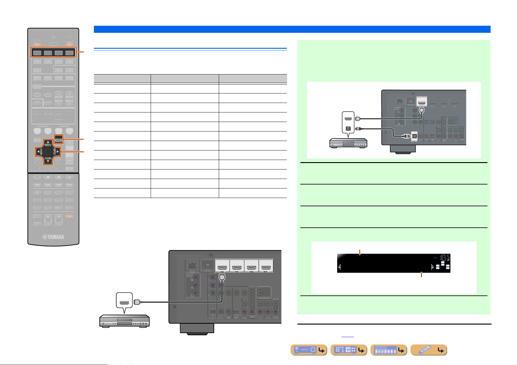
Connecting BD/DVD players and other devices
d
This unit has the following input jacks. Connect them to the appropriate output jack s on
the external components.
Input jack Video input Audio input
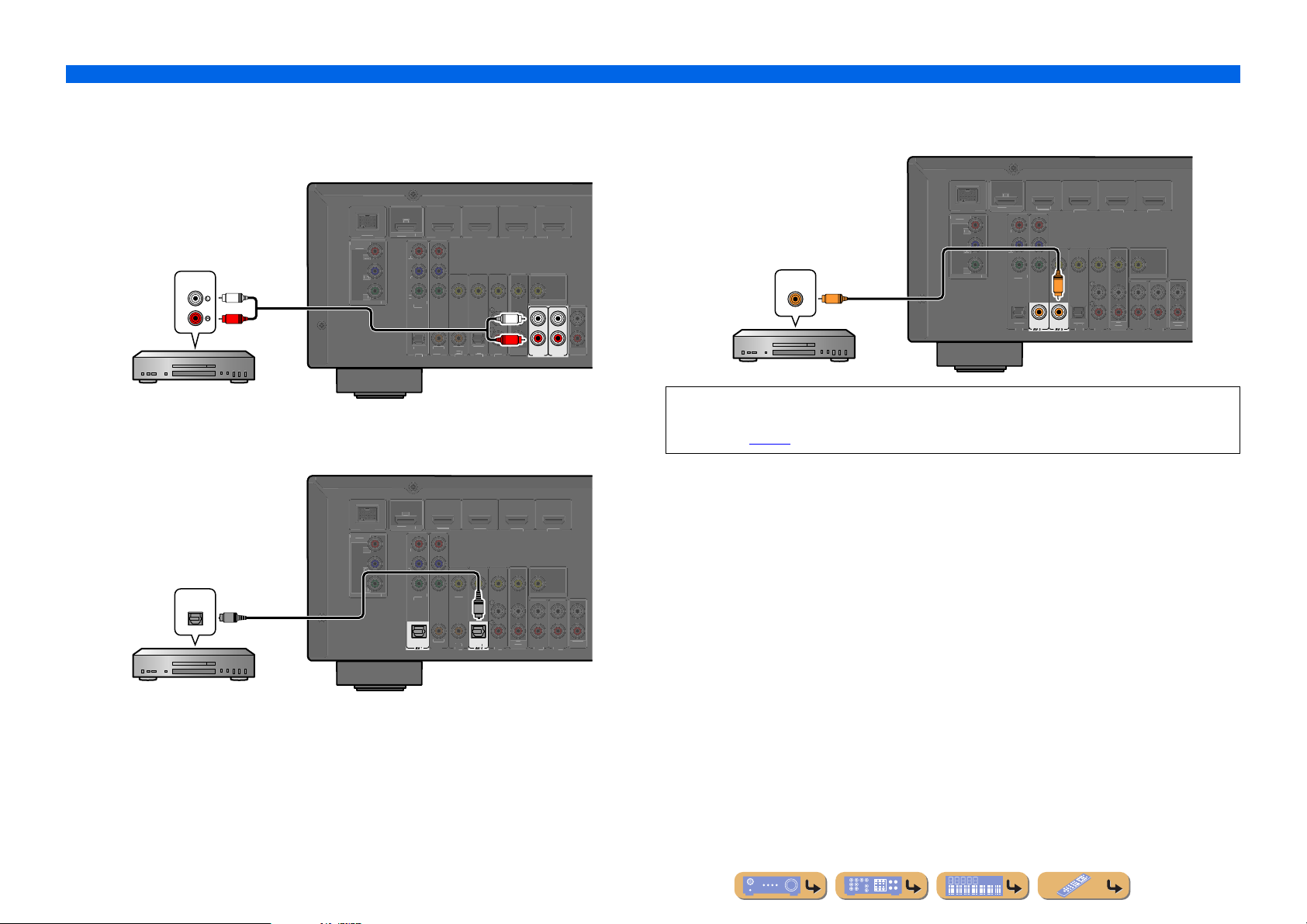
■ Receiving audio from other input sources
This unit can use the AV1-5 or AUDIO1-2 input jacks to receive audio signals from
other audio input sources.
For example, if an external device cannot prod uce audio signals from an HDMI jack,
use the following method to change the audio input.
HDMI1 HDMI HDMI
HDMI2 HDMI HDMI
HDMI3 HDMI HDMI
HDMI4 HDMI HDMI
AV1 Component video Optical
AV2 Component video Coaxial digital
q
HDMI/Audio (Optical)
output
HDMI
HDMI
OPTICAL
O
MONITOR OUT
AV3 Video Coaxial digital
ME
j
AV4 Video Optical
AV5 Video Analog (Stereo)
AUDIO1 — Analog (Stereo)
Use the dInput selector to select the desired HDMI input source.
1
BD/DVD player
AUDIO2 — Analog (Stereo)
VIDEO AUX Video Analog (Stereo)
Press qOPTION to display the Option menu. J1
2
Connecting external devices
(
)
BD/DVD
NEN
IDE
Y
O
HDMI 2 HDMI
HDMI
NEN
VIDEO
VIDEO
AXIAL
AXIA
PTICA
OPTICAL
D
T
MONITOR
UDI
T
■
NPUT
TV VOL TV CH
MUT
dInput selector
jCursor C / D / E
jENTER
qOPTION
Connecting BD/DVD players and other devices with
HDMI
Connect the device with an HDMI cable to one of the HDMI1-4 jacks.
Select the HDMI input (HDMI1-4) that the external device is connected to for
playback.
(
)
BD/DVD
T
DMI
OCK
NEN
HDMI output
HDMI
HDMI
BD/DVD player
VIDEO
P
MONITOR OUT
COMPONENT
VIDE
OPTICAL
HDMI
VIDE
AXIAL
AXIAL
PTICAL
D
TV
NITOR OUT
UT
UDIO
T
Press jCursor C until “Audio In” is displayed, and then press
jENTER.
3
Press jCursor D / E to select the audio input source.
4
Inputs that change the audio source
HDMI1
Audio;;;;;;AV1
Assignable audio input jacks
If you have selected AV1 input audio (optical digital)
VOL.
SW
C
L
SL SR
R
Once you have completed the setup, press qOPTION to close the
Option menu.
5
J
1 : See the section on “Configuring the settings specific for each input source (Option menu)” for details on
the Option menu (☞
p. 39).
En 15
■
(
)
AV 2
AV 3
AV 4
AV 5
AUDIO 1
AUDIO 2
CO
(CD)
CO
L
O
L
O
HDMI 1
B
)
3
COMPO
O
MO
P
R
Y
I
OUT
T
OUT
K
C
C
T
O
P
R
(
)
AV 1
AV 3
AV 4
AV 5
AUDIO 1
AUDIO 2
(CD)
CO
L
O
L
O
HDMI 1
B
)
3
COMPO
O
MO
P
R
Y
I
OUT
T
OUT
K
A
O
L
(
)
AV 1
AV 2
AV 3
AV 4
AUDIO 1
AUDIO 2
CO
L
(CD)
CO
O
V
O
(
D
)
HDMI 2
HDMI 3
COMPO
T
V
O
OUT
MO
OUT
OUT
A
O
OU
P
C
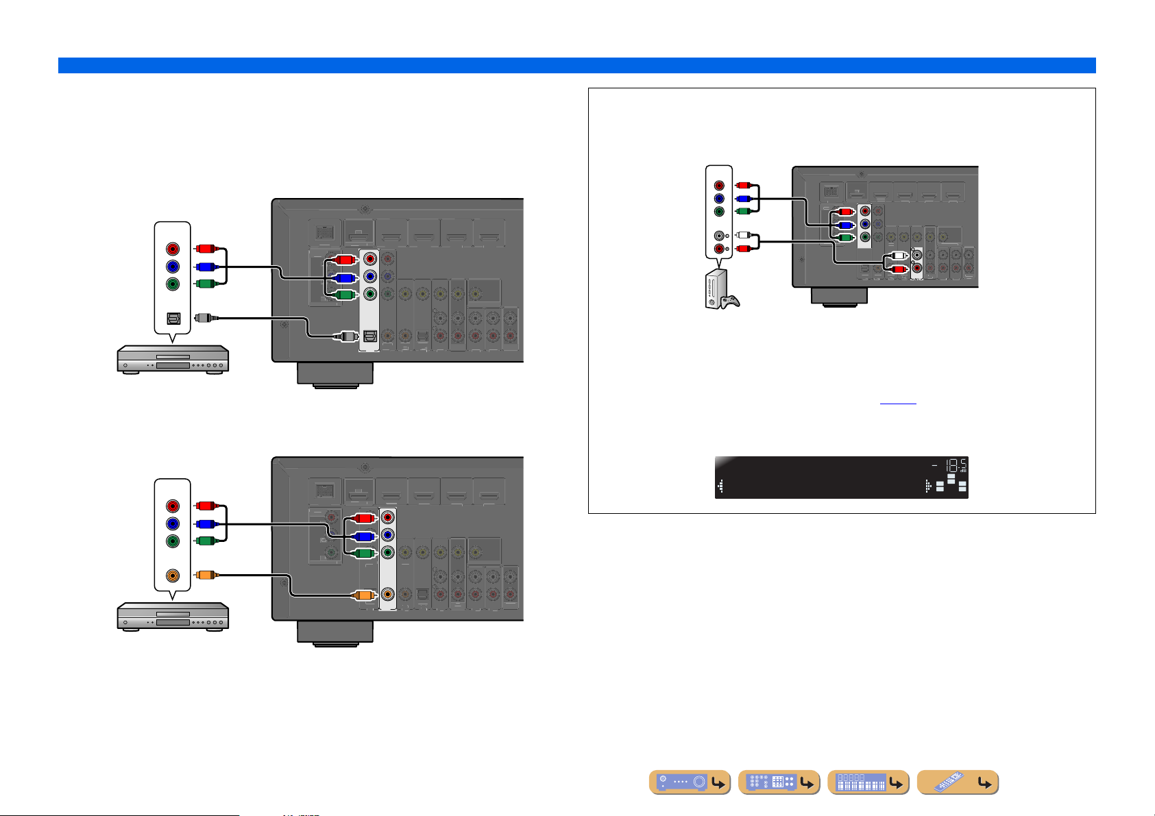
Connecting BD/DVD players and other devices with component
cables
Connect the device with a component video cable to one of the AV1-2 input jacks.
Using optical digital audio output sources
Select the AV1 input that the external device is connected to for playback.
Component video / Audio (Optical)
Using coaxial digital audio output sources
Select the AV2 input that the external device is connected to for playback.
output
COMPONENT
VIDEO
OPTICAL
BD/DVD player
AR
(
D/DVD
HDM
P
R
P
B
Y
VIDE
DOC
NENT
NITOR OUT
P
R
P
R
P
B
P
B
Y
Y
COMPONENT
VIDE
VIDEO
HDMI
MONITOR OUT
O
O
OPTICAL
AV 1
AXIA
AXIAL
PTICA
TV
OU
AUDIO
CONNECTIONS
Connecting external devices
■ Component connections to analog audio output devices
Component video / Audio
You can use the video input from the AV1-2 jacks in combination with the audio input from other
AV inputs or AUDIO1-2.
When connecting these devices, select the AV3-5 or the AUDIO1- 2 jacks as the audio input for AV1
or AV2. See “Receiving audio from other input sources” (☞
Select the AV input source (AV1-2) that is connected by component video cable to the external
device for playback.
output
COMPONENT
VIDEO
P
P
Y
AUDIO
L
R
Game console
R
B
MONITOR
AR
BD/DV
OUT
DOCK
NEN
IDE
P
R
P
R
R
P
B
P
B
Y
Y
COMPONENT
VIDEO
PTICA
IDE
L
R
AXIAL
AXIA
PTICAL
TV
NITOR
UDI
T
p. 15) for detailed setup guidance.
Component video / Audio (Coaxial)
output
COMPONENT
VIDEO
P
R
P
B
Y
COAXIAL
C
VIDE
DOC
NENT
NITOR OUT
AV1
RC
(
D/DVD
HDM
P
R
P
B
Y
OMPONEN
VIDE
VIDE
C
AXIA
COAXIAL
OPTICAL
AV 2
HDMI
MONITOR OUT
PTICA
TV
OU
AUDIO
Audio;;;AUDIO1
VOL.
SW
C
L
SL SR
R
BD/DVD player
En 16

CONNECTIONS
C
T
O
P
R
AV 1
AV 2
AV 3
AV 5
AUDIO 1
AUDIO 2
CO
(CD)
CO
L
O
HDMI 1
B
)
3
COMPO
O
MO
I
OUT
T
OUT
K
Y
P
R
ARC
C
T
O
P
R
(
)
AV 1
AV 2
AV 4
AV 5
AUDIO 1
AUDIO 2
CO
O
L
HDMI 1
B
)
3
COMPO
O
MO
I
OUT
T
OUT
K
Y
P
R
C
T
O
P
R
(
)
AV 1
AV 2
AV 3
AV 4
AUDIO 1
AUDIO 2
CO
(CD)
CO
L
O
L
O
HDMI 1
B
)
3
COMPO
O
MO
I
OUT
T
OUT
K
Y
P
R
ARC
Connecting external devices
■
Connecting BD/DVD players and other devices with video cables
Connect the external device with a video pin cable to one of the AV3-5 input jacks.
Using optical digital audio output sources
Select the AV4 input that the external device is connected to for playback.
Video / Audio (Optical)
output
VIDEO
V
OPTICAL
O
VIDE
DOC
NENT
NITOR OUT
OMPONEN
VIDE
OPTICAL
V
VIDE
O
AXIA
AXIAL
OPTICAL
TV
HDMI
MONITOR OUT
OU
AUDIO
(
D/DVD
HDM
BD/DVD player
Using coaxial digital audio output sources
Select the AV3 input that the external device is connected to for playback.
ARC
(
D/DVD
HDM
Video / Audio (Coaxial)
output
VIDEO
V
COAXIAL
C
VIDE
DOC
NENT
NITOR OUT
OMPONEN
VIDE
OPTICAL
V
VIDEO
C
COAXIAL
AXIAL
(CD)
HDMI
MONITOR OUT
PTICA
TV
OU
AUDIO
Using analog stereo audio output sources
Select the AV5 input that the external device is connected to for playback.
Video / Audio
output
VIDEO
AUDIO
BD/DVD player
DOC
NENT
VIDE
V
L
NITOR OUT
R
(
D/DVD
HDM
OMPONEN
VIDE
VIDE
AXIA
AXIAL
OPTICAL
HDMI
V
MONITOR OUT
L
R
PTICA
TV
OU
AV 5
AUDIO
BD/DVD player
En 17
CONNECTIONS
C
T
O
P
R
(
)
AV 1
AV 2
AV 3
AV 4
AV 5
CO
(CD)
CO
L
O
L
O
HDMI 1
B
)
3
COMPO
O
MO
I
OUT
T
OUT
K
Y
P
R
C
C
T
O
P
R
AV 2
AV 3
AV 5
AUDIO 1
AUDIO 2
CO
(CD)
CO
L
O
HDMI 1
B
)
3
COMPO
O
MO
P
R
Y
I
OUT
T
OUT
K
ARC
C
T
O
P
R
(
)
AV 1
AV 4
AV 5
AUDIO 1
AUDIO 2
O
L
O
HDMI 1
B
)
3
COMPO
O
MO
I
OUT
T
OUT
K
Y
P
R
C
Connecting external devices
■
Connecting CD players and other audio devices
Using analog stereo output sources
Select the audio input (AUDIO1-2) that the external device is connected to for playback.
AR
(
D/DVD
HDM
DOC
NENT
VIDE
HDMI
Audio output
AUDIO
L
NITOR OUT
OMPONEN
VIDE
VIDE
R
AXIA
AXIAL
OPTICAL
PTICA
TV
MONITOR OUT
L
R
OU
AUDIO 1
CD player
Using optical digital output sources
Select the AV input (AV1 or AV4) that the external device is connected to for playback.
(
D/DVD
HDM
DOC
NENT
VIDE
HDMI
Using coaxial digital output sources
Select the AV input (AV2 or AV3) that the external device is connected to for playback.
AR
(
D/DVD
HDM
DOC
NENT
VIDE
HDMI
Audio (Coaxial) output
COAXIAL
NITOR OUT
OMPONEN
VIDE
VIDE
C
C
COAXIAL
COAXIAL
OPTICAL
AUDIO
AUDIO 2
PTICA
(CD)
TV
MONITOR OUT
OU
AUDIO
CD player
We recommend connecting audio devices with an coaxial digital output to the AV3 coaxial digital
jack on this unit. This connection allows you to switch to the AV input 3 just by pressing the “CD”
SCENE key (☞
p. 26).
Audio (Optical) output
OPTICAL
NITOR OUT
O
OMPONEN
VIDE
OPTICAL
VIDE
O
AXIA
AXIAL
OPTICAL
TV
MONITOR OUT
OU
AUDIO
CD player
En 18
CONNECTIONS
COMPO
O
B
Y
O
(
)
AV 1
AV 2
AV 3
AV 4
AV 5
AUDIO 1
AUDIO 2
CO
(CD)
CO
O
O
(
D
)
HDMI
HDMI
HDMI
COMPO
T
O
B
O
MO
DOC
C
Connecting external devices
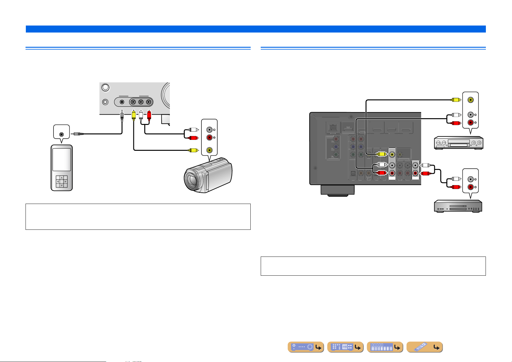
Connecting video cameras and portable audio players
Use the VIDEO AUX jacks on the front panel to temporarily conn ect video cameras, game consoles, or
portable audio devices to the receiver.
Select the V-AUX input to use these connected devices.
RADIO
AUX
PORTABLE
VIDEO
VIDEO
AUDIO
LR
R
V
L
AUDI O
L
Audio output
R
VIDEO
Video output
V
STRAIGHT
AUDIO OUT
Audio output
Portable audio player Video cameras
• Be sure to turn down the volume when connecting this unit and the other devices.
• When external components are connected to both the PORTABLE jack and the AUDIO jacks, the sound
output from the PORTABLE jack is transmitted.
Transmitting input A/V to external devices
This receiver can transmit selected incoming analog audio/video signals to e xternal de vices through the
AV OUT and AUDIO OUT jacks. You can record these input audio and video signals to VCRs or
similar devices, or send them to other TVs or external devices.
Video / Audio
input
VIDEO
V
AUDIO
L
AR
BD/DV
UT
NEN
VIDE
P
MONITOR OUT
K
P
NENT
VIDE
PTICAL
2
V
VIDE
L
R
AXIAL
AXIAL
PTICAL
4
3
NITOR OUT
L
AV
OUT
R
AUDIO
OUT
Using the AV OUT jacks
Connect this jacks to the external device’s video input jack and analog audio input jacks.
R
VCR
Audio input
AUDIO
L
R
Audio recorder
Using the AUDIO OUT jacks
Connect this jack to the external device’s analog audio input jacks.
HDMI audio/video signals, component video signals, and digital audio signals cannot be transmitted
from these jacks.
En 19

Connecting the FM/AM antennas
C
SURROUND
3
FRO
S
S
An indoor FM antenna and an AM loop antenna are included with this receiver . Connect these anten nas
properly to their respective jacks.
Indoor FM antenna
AM loop antenna
Position the AM antenna away from the receiver. The
wires of the AM antenna have no polarity.
You can connect e ither wire to the AM jack or the
GND jack.
CONNECTIONS
DMI
FM
GND
AM
PEAKER
ENTER
NT
Connecting the AM loop antenna
ReleaseInsertPress and hold
■ Improving FM reception
We recommend using an outdoor antenna. For more information, consult the nearest authorized
dealer.
■ Improving AM reception
Connect this unit to an outdoor antenna with a 5-10 m vinyl-coated wire. Make sure the AM loop
antenna is still connected.
Connecting the GND jack can reduce noise. Connect the jack to a store-bought ground bar or copper
plate with a vinyl-covered wire and bury this new attachment in moist ground.
The GND jack is not to be connected to the ground socket of an electrical outlet.
En 20
CONNECTIONS
Set up the speaker parameters automatically (YPAO)
This unit is equipped with a YPAO (Yamaha Parametric room Acoustic Optimizer) that adjusts the status, size, and volume balance of the speakers in order to provide an optimal sound field. Using
YPAO allows you to automatically configure settings for which specialist knowledge is usually needed, such as adjusting speaker output and acoustic parameters to suit your listening room (the room
in which this unit is placed). J1
When you use YPAO, a test tone will be output from the
speakers for approximately three minutes and acoustic
measuring will be performed. When using YPAO, be careful of
the following.
• The test tone is output at high volume. Please refr ain from using
this function at night when it may be a nuisance to others nearby.
• Please take care that the test tone does not frighten any small
children.
Check the following before using YPAO.
1
This unit
• The headphones are removed.
Subwoofer
• The power is turned on.
• The auto power-off function (if present) is set to off.
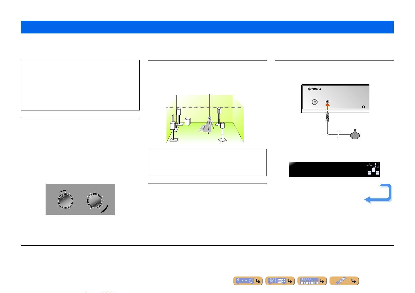
• Volume is set to approximately half, and the cross-over frequency (if
present) is set to maximum.
CROSSOVER/
VOLUME
HIGH CUT
Place the supplied YP A O microphone at ear height in
your listening position.
2
Face the head of the YPAO microphone upwards.
YPAO microphone
When positioning the microphone, we recommend that you use
equipment that allows you to adjust the height (such as a tripod)
as a microphone stand. When using a tripod, use the tripod
screws to fix the microphone in place.
Switch this unit on.
3
Connect the YP A O micr ophone to the YPAO MIC jack
on the front panel.
4
YPAO MIC
INFO
“MIC ON. YP AO START” appears on the front panel display, and
then changes to display the following. J2
YPAO
Press[SETUP]
VOL.
SW
C
L
SL SR
Continues to the
next page
R
MIN MAX
Subwoofer examples
J
1 : When you have changed the number of speakers or the locations in which they
are installed, first use YPAO to adjust the speaker balance.
J
2 : To cancel measurement, disconnect the YPAO microphone.
MIN MAX
En 21
856
9010
1
234
REC
I
E
SC
O
RETURN
VOLU
R
SU
S
H
A
O
TRANSMI
T
S
P
3
3
5
TUNER
INFO
MEMO
PRES
G
MO
C
S
O
B
D
CD
O
MUTE
TO
MENU
POP-UP
MENU
DIS
Y
SOURC
CO
T
[
]
[
]
E
LEE
DMI
V-AUX
A
B
ET
RY
ENHANCE
VIE MUSI
D
VD
SETUP
P
NPUT
MUT
TRAIGHT
ENE
TV
ENTER
TV VOL TV CH
TERE
PTION
PLA
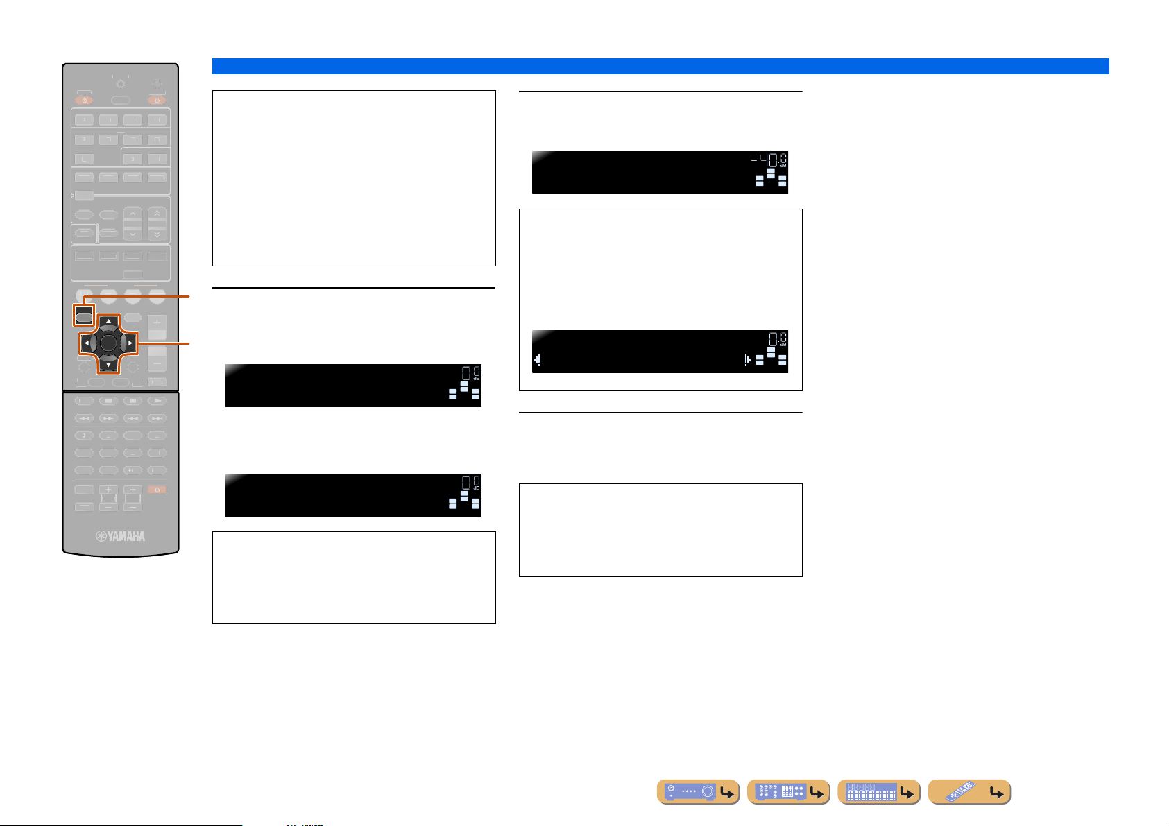
iSETUP
jCursor C / D / E
jENTER
UDI
DE SE
RECEIVER
DOCK
TUNIN
R. DECODE
RADI
ME
This completes preparations. To achieve more
accurate results, be careful of the following when
measuring.
• Measuring will take approximately three minutes.
Keep the room as quiet as possible during
measurement.
• Wait in the corner of the listening room during
measurement or leave it entirely , to av oid becoming an
obstruction between the speakers and the YPAO
microphone.
i
Press iSETUP to start measurement.
5
Display during measurement
j
YPAO
Progress00%
The following display appears if measurement finishes
without any problems.
YPAO
YPAOComplete
NOTE
When a problem occurs, an error message or report
appears either during or after measurement. Use the
following page as a reference to solve the problem,
and carry out YPAO again.
VOL.
VOL.
SW
C
L
SL SR
SW
C
L
SL SR
CONNECTIONS
Set up the speaker parameters automatically (YPAO)
Press jENTER to apply the results of
measurement.
6
YPAO
Disconnect MIC
You can use the following method to cancel
measurement results if you want to redo the
measuring. Press jCursor C to switch to the
following display, the use jCursor D / E to select
“Cancel” and press jENTER. After this operation,
use the same procedure to carry out YPAO again.
YPAO
Set>Cancel
R
Remove the YPAO microphone.
7
YPAO finishes automatically when the YPAO
microphone is removed.
R
The YP AO microphone is sensitive to heat. When you
have finished measuring, store the microphone out of
direct sunlight, and away from locations that may
experience high temperatures, such as on top of AV
equipment.
VOL.
VOL.
SW
C
L
SL SR
SW
C
L
SL SR
R
R
En 22
 Loading...