

Yamaha HS-50-M, HS-80-M Service manual
POWERED MONITOR SPEAKER
HS80M/HS50M
SERVICE MANUAL
このサービスマニュアルはエコパルプ
(ECF:無塩素系漂白パルプ)を使用しています。
011806
PA
HS80M: 200510-47250
HS50M: 200510-26250
■ CONTENTS (目次)
HS80M SPECIFICATIONS (総合仕様)..................................... 3
HS50M SPECIFICATIONS (総合仕様)..................................... 4
DIMENSIONS (寸法図)........................................................... 5
PANEL LAYOUT (パネルレイアウト)...................................... 6
CIRCUIT BOARD LAYOUT (ユニットレイアウト).................. 7
HS80M DISASSEMBLY PROCEDURE (分解手順)................. 8
HS50M DISASSEMBLY PROCEDURE (分解手順)............... 11
CIRCUIT BOARDS (シート基板図)........................................ 14
HS80M INSPECTIONS (検査)............................................... 15
HS50M INSPECTIONS (検査)............................................... 16
BLOCK DIAGRAM (ブロックダイアグラム)
OVERALL CIRCUIT DIAGRAM (総回路図)
PARTS LIST
HAMAMATSU, JAPAN
Copyright (c) Yamaha Corporation. All rights reserved. PDF Printed in Japan ’05.12
HS80M/HS50M
IMPORTANT NOTICE
This manual has been provided for the use of authorized Yamaha Retailers and their service personnel. It has been assumed
that basic service procedures inherent to the industry, and more specifically Yamaha Products, are already known and understood by the users, and have therefore not been restated.
WARNING : Failure to follow appropriate service and safety procedures when servicing this product may result in per-
IMPORTANT : This presentation or sale of this manual to any individual or firm does not constitute authorization, certifi-
The data provided is believed to be accurate and applicable to the unit (s) indicated on the cover. The research engineering, and
service departments of Yamaha are continually striving to improve Yamaha products. Modifications are, therefore, inevitable
and changes in specification are subject to change without notice or obligation to retrofit. Should any discrepancy appear to
exist, please contact the distributor’s Service Division.
WARNING : Static discharges can destroy expensive components. Discharge any static electricity your body may have
IMPORTANT : Turn the unit OFF during disassembly and parts replacement. Recheck all work before you apply power
sonal injury, destruction of expensive components and failure of the product to perform as specified. For
these reasons, we advise all Yamaha product owners that all service required should be performed by an
authorized Yamaha Retailer or the appointed service representative.
cation, recognition of any applicable technical capabilities, or establish a principal-agent relationship of
any form.
accumulated by grounding yourself to the ground bus in the unit (heavy gauge black wires connect to
this bus).
to the unit.
WARNING: CHEMICAL CONTENT NOTICE!
The solder used in the production of this product contains LEAD. In addition, other electrical/electronic and/or plastic (Where
applicable) components may also contain traces of chemicals found by the California Health and Welfare Agency (and possibly
other entities) to cause cancer and/or birth defects or other reproductive harm.
DO NOT PLACE SOLDER, ELECTRICAL/ELECTRONIC OR PLASTIC COMPONENTS IN YOUR MOUTH FOR ANY REASON WHAT
SO EVER!
Avoid prolonged, unprotected contact between solder and your skin! When soldering, do not inhale solder fumes or expose
eyes to solder/flux vapor!
If you come in contact with solder or components located inside the enclosure of this product, wash your hands before handling
food.
WARNING: THIS APPARATUS MUST BE EARTHED
IMPORTANT
THE WIRES IN THIS MAINS LEAD ARE COLOURED IN
ACCORDANCE WITH THE FOLLOWING CODE:
GREEN-AND-YELLOW : EARTH
BLUE : NEUTRAL
BROWN : LIVE
As the colours of the wires in the mains lead of this apparatus may
not correspond with the coloured markings identifying the terminals in
your plug, proceed as follows:
The wire which is coloured GREEN and YELLOW must be
connected to the terminal in the plug which is marked by the letter E
or by the safety earth symbol or coloured GREEN and YELLOW.
The wire which is coloured BLUE must be connected to the
terminal which is marked with the letter N or coloured BLACK.
The wire which is coloured BROWN must be connected to the terminal
which is marked with the letter L or coloured RED.
* This applies only to products distributed by YAMAHA KEMBLE
MUSIC (U.K.) LTD.
■ WARNING
Components having special characteristics are marked and must be
replaced with parts having specification equal to those originally installed.
印の部品は、安全を維持するために重要な部品です。交換する場合は、
安全のために必ず指定の部品をご使用ください。
2
HS80M
■ HS80M SPECIFICATIONS (総合仕様)
General specifications
Type ................................................ Biamp 2-way Powered speaker
Crossover Frequency ..................... 2 kHz
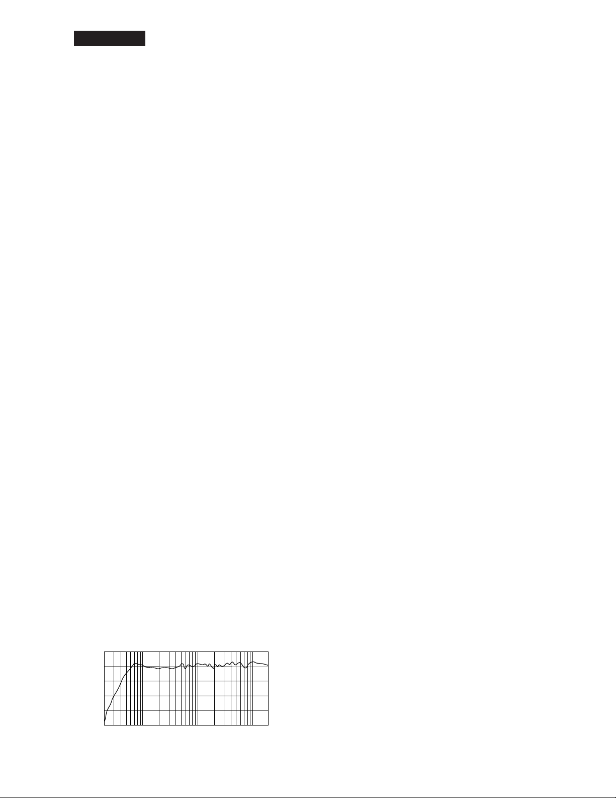
Overall Frequency Response ......... 42 Hz-20 kHz (-10 dB)
Dimensiones (W x H x D)............... 250 x 390 x 332 mm (9-13/16” x 15-3/8” x 13-1/6”)
Weight ............................................ 11.3 kg
Speaker Components
Speaker Components .................... LF: 8" Cone (Magnetic shielding Type)
HF: 1" Dome (Magnetic shielding Type)
Enclosure ....................................... Type: Bass-reflex Type
Material: MDF
Amp. unit
Output Power.................................. Total: 120 W (dynamic power)
(LF: 75 W, 4 ohms, 1 kHz)
(HF: 45 W, 8 ohms, 10 kHz)
Input Sensitivity/Impedance ........... -10 dBu/ 10 k-ohms
Input Connectors (parallel) ............ 1: XLR-3-31 type (balanced)
2: PHONE (balanced)
Controls .......................................... LEVEL control (+4 dB/ center click)
LOW CUT switch (FLAT/ 80/ 100 Hz, 12 dB/ octave)
MID EQ switch (+/- 2 dB at 2 kHz)
HIGH TRIM switch (+/- 2 dB at HF)
ROOM CONTROL switch (0/ -2/ -4 dB under 500 Hz)
Power Indicator .............................. Power ON: White LED
Power Consumption ....................... 60 W
HS80M/HS50M
●総合仕様
形式 ................................................ バイ・アンプ2ウェイパワード・スピーカー
クロスオーバー周波数 ................... 2kHz
再生周波数帯域 .............................. 42Hz〜20kHz(-10dB)
最大外形寸法(W×H×D).............. 250×390×332mm
質量 ................................................ 11.3kg
●スピーカー部
スピーカーユニット ....................... LF:20cmコーン(防磁型)
HF:2.5cmドーム(防磁型)
エンクロージャー........................... 方式:バスレフ型
材質:MDF
●アンプ部
最大出力 ......................................... 総合:120W(ダイナミックパワー)
(LF:75W、4ohms、1kHz)
(HF:45W、8ohms、10kHz)
入力感度/インピーダンス ............... -10dBu/10k-ohms
入力端子(パラレル)....................... 1:XLR-3-31タイプ端子(バランス)
2:フォーン端子(バランス)
コントロール .................................. LEVELコントロール(+4dB/centerclick)
LOWCUTスイッチ(FLAT/80/100Hz、12dB/octave)
MIDEQスイッチ(+/-2dBat2kHz)
HIGHTRIMスイッチ(+/-2dBatHF)
ROOMCONTROLスイッチ(0/-2/-4dBunder500Hz)
インジケーター .............................. 電源ON:白色LED
消費電力 ......................................... 60W
• Performance graph (特性図)
+10
0
-10
-20
-30
RESPONSE (dB)
-40
20
FREQUENCY (Hz)
10k1k100
3
HS80M/HS50M
■ HS50M SPECIFICATIONS (総合仕様)
General specifications
Type ................................................ Biamp 2-way Powered speaker
Crossover Frequency ..................... 3 kHz
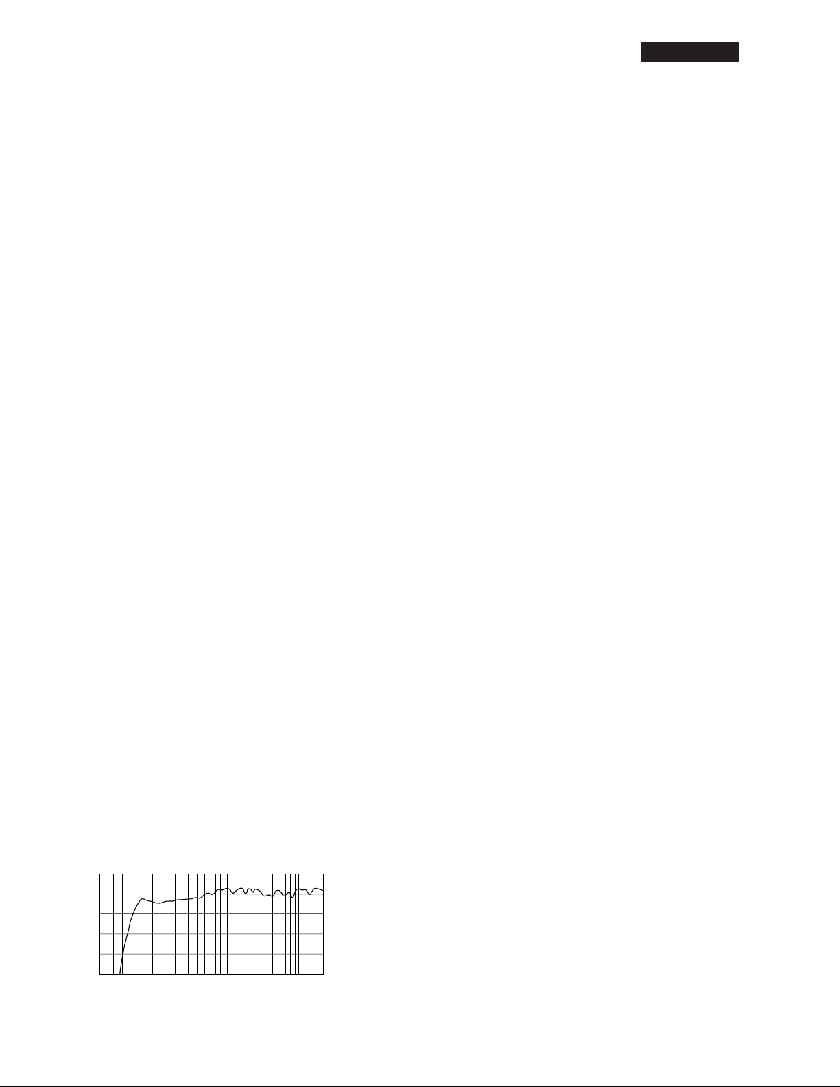
Overall Frequency Response......... 55 Hz-20 kHz (-10 dB)
Dimensiones (W x H x D)............... 165 x 268 x 222 mm (6-1/2” x 10-9/16” x 8-3/4”)
Weight ............................................ 5.8 kg
Speaker Components
Speaker Components .................... LF: 5" Cone (Magnetic shielding Type)
HF: 0.75" Dome (Magnetic shielding Type)
Enclosure ....................................... Type: Bass-reflex Type
Material: MDF
Amp. unit
Output Power.................................. Total: 70 W (dynamic power)
(LF: 45 W, 4 ohms, 1 kHz)
(HF: 25 W, 8 ohms, 10 kHz)
Input Sensitivity/Impedance ........... -10 dBu/ 10 k-ohms
Input Connectors (parallel) ............ 1: XLR-3-31 type (balanced)
2: PHONE (balanced)
Controls .......................................... LEVEL control (+4 dB/ center click)
LOW CUT switch (FLAT/ 80/ 100 Hz, 12 dB/ octave)
MID EQ switch (+/- 2 dB at 2 kHz)
HIGH TRIM switch (+/- 2 dB at HF)
ROOM CONTROL switch (0/ -2/ -4 dB under 500 Hz)
Power Indicator .............................. Power ON: White LED
Power Consumption ....................... 45 W
HS50M
●総合仕様
形式 ................................................ バイ・アンプ2ウェイパワード・スピーカー
クロスオーバー周波数 ................... 3kHz
再生周波数帯域 .............................. 55Hz〜20kHz(-10dB)
最大外形寸法(W×H×D).............. 165×268×222mm
質量 ................................................ 5.8kg
●スピーカー部
スピーカーユニット ....................... LF:13cmコーン(防磁型)
HF:2.0cmドーム(防磁型)
エンクロージャー........................... 方式:バスレフ型
材質:MDF
●アンプ部
最大出力 ......................................... 総合:70W(ダイナミックパワー)
(LF:45W、4ohms、1kHz)
(HF:25W、8ohms、10kHz)
入力端子(パラレル)....................... 1:XLR-3-31タイプ端子(バランス)
2:フォーン端子(バランス)
コントロール .................................. LEVELコントロール(+4dB/centerclick)
LOWCUTスイッチ(FLAT/80/100Hz、12dB/octave)
MIDEQスイッチ(+/-2dBat2kHz)
HIGHTRIMスイッチ(+/-2dBatHF)
ROOMCONTROLスイッチ(0/-2/-4dBunder500Hz)
インジケーター .............................. 電源ON:白色LED
消費電力 ......................................... 45W
• Performance graph (特性図)
4
+10
0
-10
-20
-30
RESPONSE (dB)
-40
20
10k1k100
FREQUENCY (Hz)
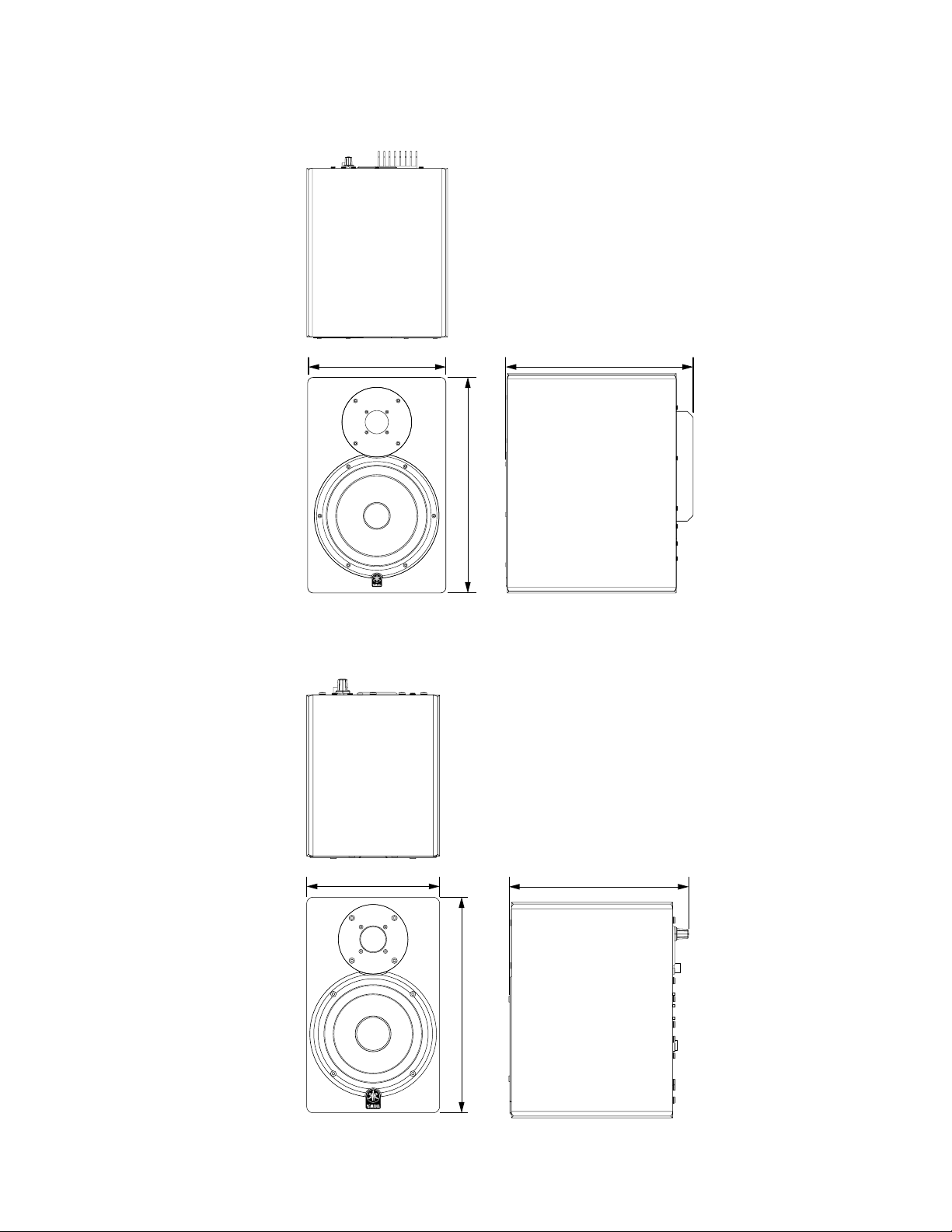
■ DIMENSIONS (寸法図)
• HS80M
250 (9-13/16") 332 (13-1/16")
HS80M/HS50M
• HS50M
390 (15-3/8")
165 (6-1/2") 222 (8-3/4")
Unit: mm (inch)
単位:mm(インチ)
268 (10-9/16")
Unit: mm (inch)
単位:mm(インチ)
5
HS80M/HS50M
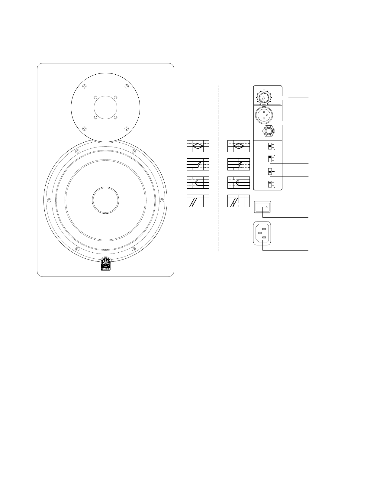
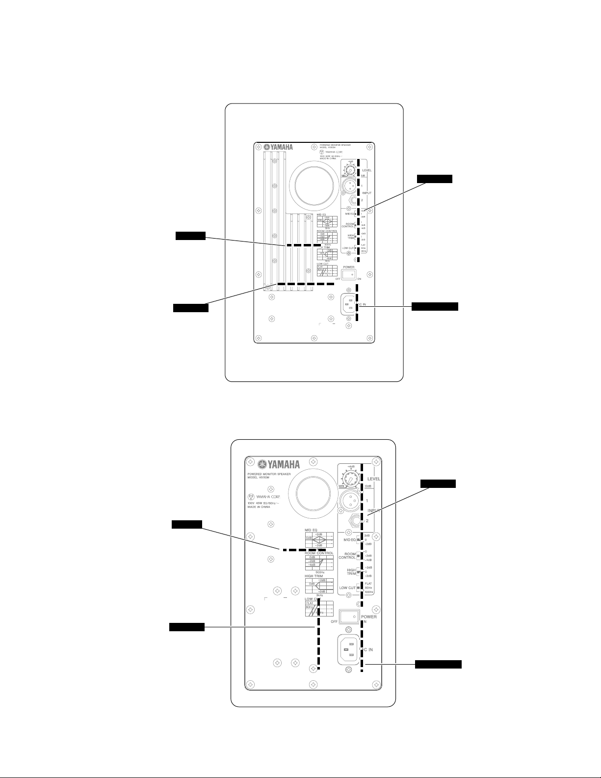
■ PANEL LAYOUT (パネルレイアウト)
MID EQ
+2dB
0dB
-2dB
2kHz
ROOM CONTROL
0dB
-2dB
-4dB
500Hz
HIGH TRIM
+2dB
0dB
-2dB
2kHz
LOW CUT
FLAT
80Hz
100Hz
HS50MHS80M
MID EQ
+2dB
0dB
-2dB
2kHz
ROOM CONTROL
0dB
-2dB
-4dB
500Hz
HIGH TRIM
+2dB
0dB
-2dB
3kHz
LOW CUT
FLAT
80Hz
100Hz
OFF
+4dB
MIN
MID EQ
ROOM
CONTROL
HIGH
TRIM
LOW CUT
LEVEL
-10dB
1
INPUT
2
+2dB
0
-2dB
0
-2dB
-4dB
+2dB
0
-2dB
FLAT
80Hz
100Hz
POWER
ON
2
3
4
5
6
7
1
1 POWER switch
2 LEVEL control
3 INPUT 1, 2 connector
4 MID EQ switch
5 ROOM CONTROL switch
6 HIGH TRIM switch
7 LOW CUT switch
8 AC IN Connector
9 Power indicator
9
1
POWER スイッチ
2
LEVEL コントロール
3
INPUT1、2 端子
4
MIDEQ スイッチ
5
ROOMCONTROL スイッチ
6
HIGHTRIM スイッチ
7
LOWCUT スイッチ
8
ACIN 端子
9
Powerインジケータ
AC IN
8
6
■ CIRCUIT BOARD LAYOUT (ユニットレイアウト)
• HS80M
AMP
(LF 2/4)
HS80M/HS50M
INPUT
(LF 3/4)
• HS50M
TRANS
(LF 4/4)
AMP
(LF 2/4)
AC INLET
(LF 1/4)
INPUT
(LF 3/4)
TRANS
(LF 4/4)
AC INLET
(LF 1/4)
7
HS80M/HS50M
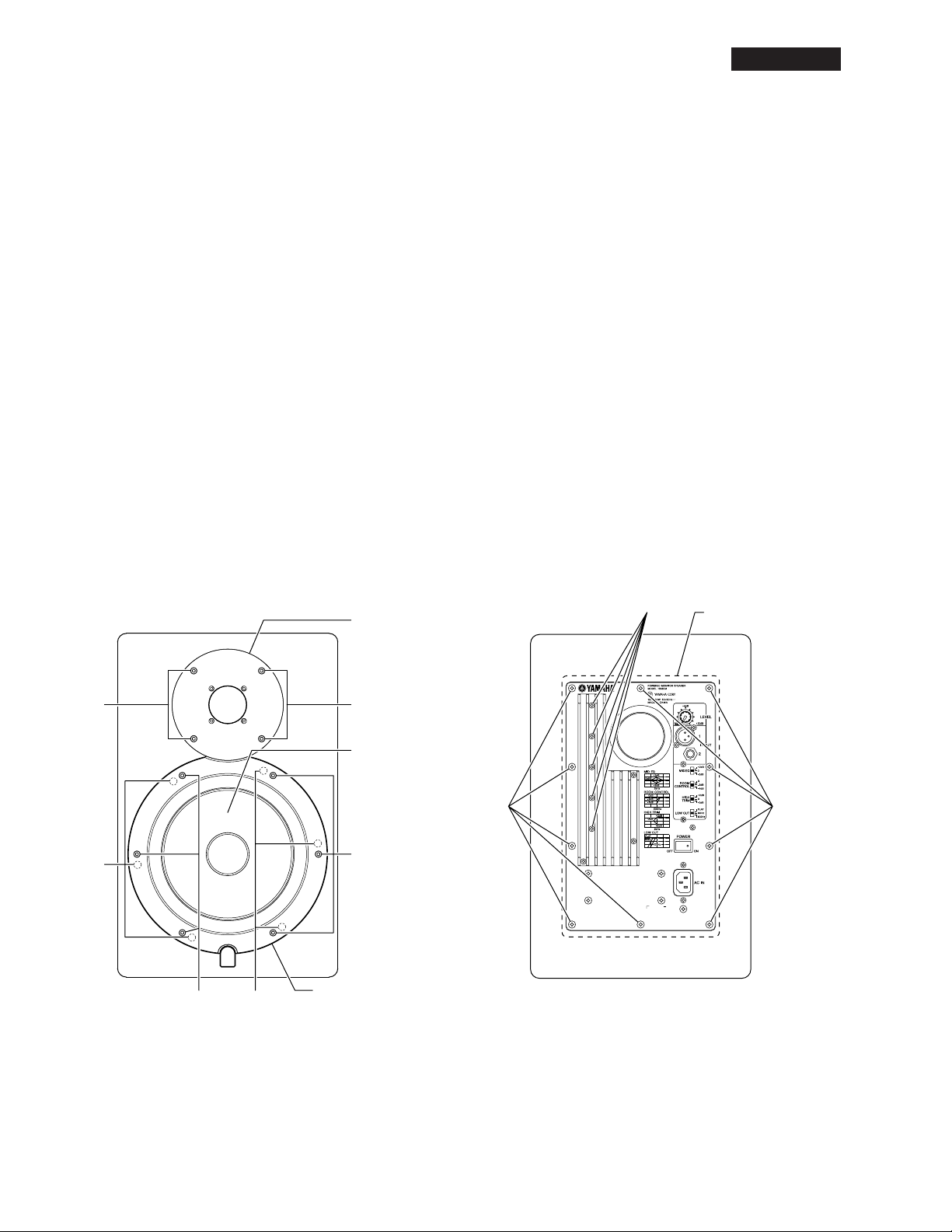
■ HS80M DISASSEMBLY PROCEDURE (分解手順)
HS80M
1. Woofer (Time required: about 1 minute)
1-1 Remove the six (6) screws marked [55]. The woofer
ring can then be removed. (Fig. 1)
1-2 Remove the six (6) screws marked [40]. The woofer
can then be removed. (Fig. 1)
2. Tweeter (Time required: about 1 minute)
Remove the four (4) screws marked [20]. The tweeter
can then be removed. (Fig. 1)
3. Rear Panel Assembly (Time required: about
1 minute)
Remove the ten (10) screws marked [155]. The rear
panel assembly can then be removed. (Fig. 2)
4. AMP Circuit Board
(Time required: about 2 minutes)
4-1 Remove the rear panel assembly.(See procedure 3.)
4-2 Remove the five (5) screws marked [90]. The AMP
unit can then be removed. (Fig. 2)
* At this time, be careful not to lose the spacer which
also comes off.
Tweeter
ツィーター
1. ウーファー(所要時間:約1分)
1-1 [55]の六角孔付きボルトを6本外し、ウーファーリン
グを外します。(図1)
1-2 [40]のネジを6本外し、ウーファーを外します。(図1)
2. ツィーター(所要時間:約1分)
[20]の六角孔付きボルトを4本外し、ツィーターを外
します。(図1)
3. リアパネルAssy(所要時間:約1分)
[155]のネジを10本外し、リアパネルAssyを外し
ます。(図2)
4. AMPシート(所要時間:約2分)
4-1 リアパネルAssyを外します。(3項参照)
4-2 [90]のネジを5本外し、AMPユニットを外します。
(図2)
* このとき、スペーサーも同時に外れますのでなく
さないよう注意してください。
[90]
Rear Panel Assembly
リアパネルAss'y
[20] [20]
Woofer
ウーファー
[40]
[55]
[20]: Hexagonal Socket Tapping Screw 4x20 (WG341100) 6
角穴付きTP1種
[40]: Bind Head Tapping Screw 4x16 (WG540200) +バインド
TP1種
[55]: Hexagonal Socket Tapping Screw 4x20 (WG341100) 6
角穴付きTP1種
[40]
Fig. 1(図1)
[55]
Woofer Ring
ウーファーリング
[155][155]
Fig. 2(図2)
[90]: Bind Head Tapping Screw-S 3x16 (WG341600) +バイン
ドSタイト
[155]: Bind Head Tapping Screw 4x16 (WG540200) +バインド
TP1種
8
HS80M
[C]
[C]
[B]
IC801
IC802
AMP mounting BRACKET
(AMP取付金具)
AMP mounting BRACKET
(AMP取付金具)
AMP circuit board
(AMPシート)
SPACER
(スペーサー)
HEAT SINK
(放熱板)
INPUT Circuit Board
(INPUTシート)
INPUT Circuit Board
(INPUTシート)
CASE PWB
(ケースPWB)
CASE PWB
(ケースPWB)
[G]
HS80M/HS50M
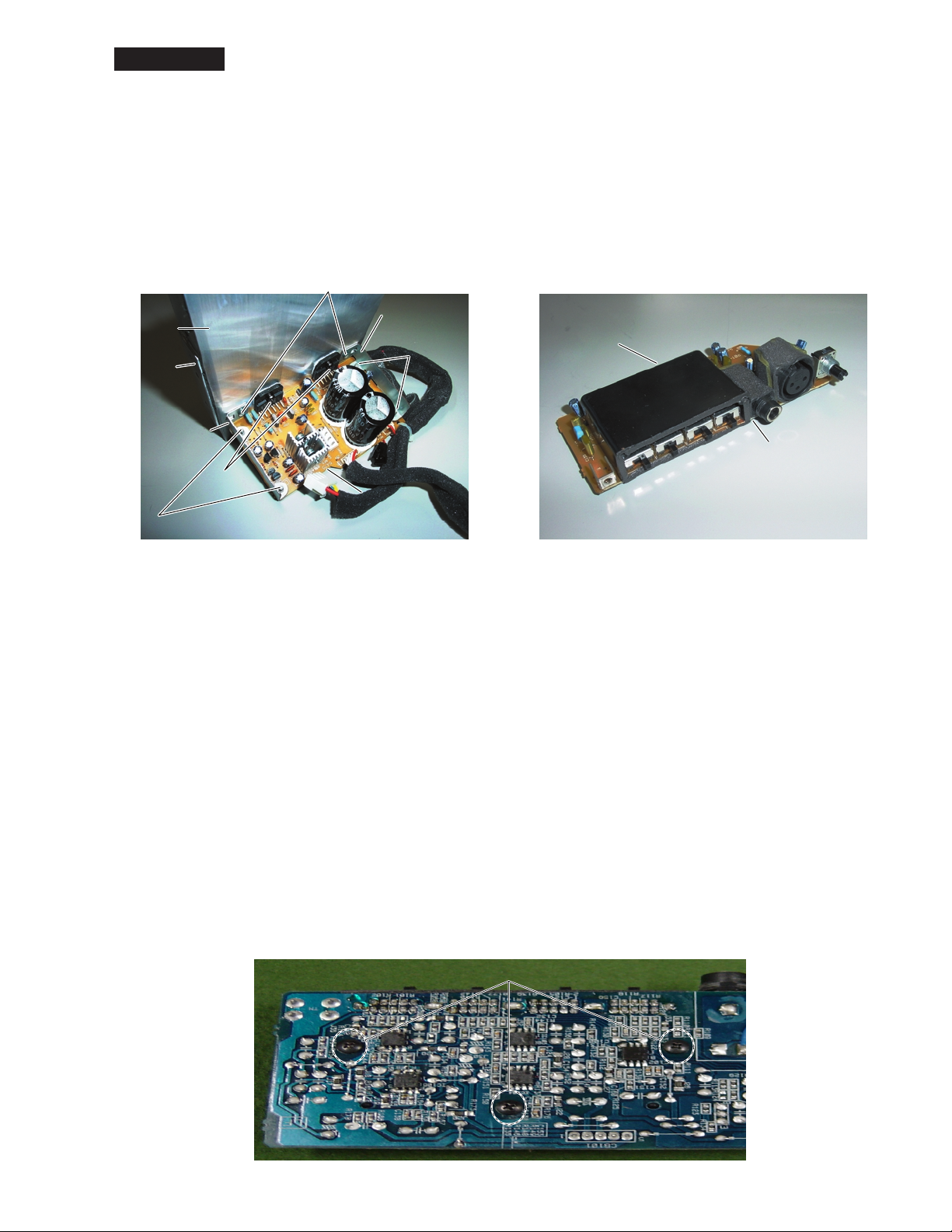
4-3 Unsolder soldered parts (22 locations) on the pat-
tern side of IC801 and IC802. (Photo. 1)
4-4 Remove the two (2) screws marked [A] and remove
the heat sink with IC801 and IC802. (Photo. 1)
Remove the two (2) screws marked [B] and remove
IC801 and IC802. (Photo. 1)
4-5 Remove the four (4) screws marked [C], remove the
AMP mounting bracket. The AMP circuit board can
then be removed. (Photo. 1)
[A]
AMP mounting BRACKET
HEAT SINK
(放熱板)
SPACER
(スペーサー)
AMP mounting BRACKET
(AMP取付金具)
IC802
IC801
(AMP取付金具)
[B]
AMP circuit board
(AMPシート)
[C]
4-3 IC801とIC802のパターン側のハンダ(22カ所)を外し
ます。(写真1)
4-4 [A]のネジ2本を外し、放熱板(IC801、IC802付)を外
します。(写真1)
[B]のネジ2本を外し、IC801とIC802を外します。
(写真1)
4-5 [C]のネジ4本を外し、AMP取付金具を外してAMP
シートを取り出します。(写真1)
[C]
Photo. 1(写真1)
<AMP Unit>
<AMPユニット>
5. INPUT Circuit Board
(Time required: about 3 minutes)
5-1 Remove the rear panel assembly. (See procedure 3.)
5-2 Remove the four (4) screws marked [110] and the
screw marked [115]. (Fig. 3)
5-3 Remove the LEVEL knob, the hexagonal nut [E] and
washer [D]. (Fig. 3, Photo. 5)
5-4 Remove the hexagonal nut [F] on the phone type in-
put connector. The INPUT assembly can then be removed. (Photo. 5)
5-5 Remove the three (3) screws marked [G] and remove
the case PWB. (Photo. 3)
The Input circuit board can then be removed.
* The case PWB is not a component of the INPUT cir-
cuit board. When replacing the INPUT circuit board,
remove the case PWB and reuse it.
Photo. 2(写真2)
<INPUT Assembly>
<InputAssy>
5. INPUTシート(所要時間:約3分)
5-1 リアパネルAssyを外します。(3項参照)
5-2 [110]のネジ4本と[115]のネジ1本を外します。
(図3)
5-3 LEVELつまみと[E]の六角ナットおよび[D]のワッ
シャを外します。(図3、写真5)
5-4 フォーンタイプ入力端子の六角ナット[F]を外し、
INPUTAssyを外します。(写真5)
5-5 [G]のネジを3本外してケースPWBを外し、INPUT
シートを取り出します。(写真3)
* ケースPWBはINPUTシートの構成部品ではありませ
ん。シート交換時には、取外して使用してくださ
い。
[G]
Photo. 3(写真3)
9
 Loading...