

Page 1

Factory Pipe
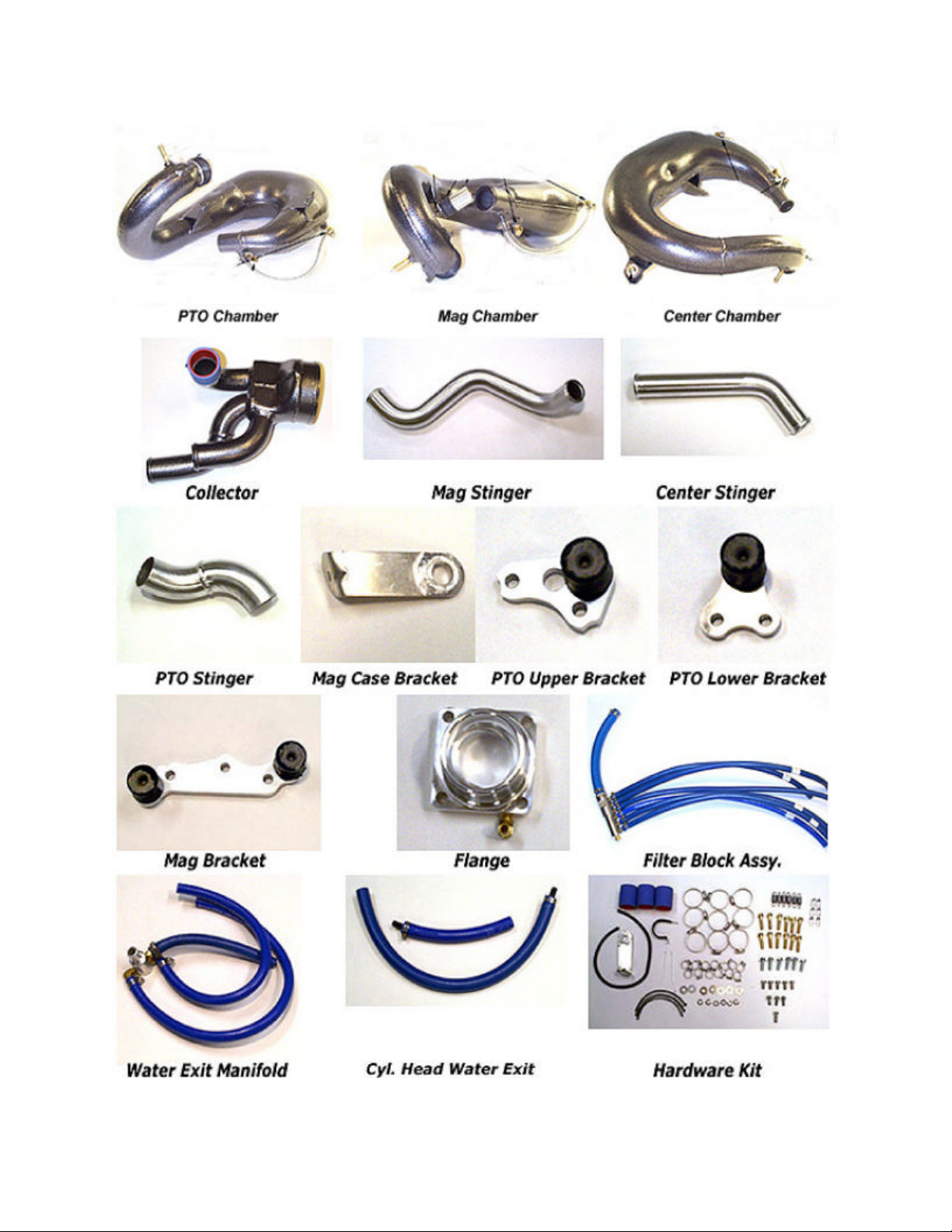
Bill Of Materials
Yamaha GP1200R
Item Qty Part Number Part Description
1 3 COMASM0690 Yam GP 800/XL1200/GP1200R flange Assy.
2 1 COMASM0840 GP1200R Collector Assy.
3 1 COMASM0821 GP1200R Mag Chamber Assy.
4 1 COMASM0822 GP1200R Center Chamber Assy.
5 1 COMASM0823 GP1200R PTO Chamber Assy.
6 1 COMST12002 Mag Stinger Tailpipe (long S-bend)
7 1 COMST12003 Center Stinger Tailpipe (45 deg. Bend)
8 1 COMST12001 PTO Stinger Tailpipe (short S-Bend)
9 1 COMASM0825 GP1200R/XL1200 Mag Bracket-Mount Assy.
10 1 COMASM0826 GP1200R PTO Upper Bracket-Mount Assy.
11 1 COMASM0827 GP1200R/XL1200 PTO Lower Bracket Assy.
12 1 COMASM0828 GP1200R Filter Block Assy.
13 1 COMASM0829 GP1200R Water Exit Manifold Assy.
14 1 COMASM0844 GP1200R Cylinder Head Exit Waterlines
15 1 COMASM0832 GP1200R Hardware Kit (Consisting of Parts #16-32)
16* 6 COMASM0790 Stainless Steel Exhaust Springs (with clear hose cover)
17* 12 COMFAS0050 10mm x 40mm Hex Head Bolts
18* 6 COMFAS0002 10mm Stainless Steel Spring Hook
19* 9 COMCLP0020 #32 Stainless Steel Hose Clamp
20* 3 COMHOS00703 1-3/4" x 2-1/2" Silicone Coupler
22* 13 COMCLP0010 #6 S.S. Steel Hose Clamp
23* 7 COMFAS0086 3/8" S.S. Flat Washers
24* 6 COMFAS0046 10mm x 30mm Flange Head Bolt
25* 1 COMFAS0280 3/8"-16 x 1" S.S. Hex Head Bolt
26* 5 COMFAS0100 3/8"-16 x 3/4" S.S. Hex Head Bolt
27* 6 COMFAS0040 10mm S.S. Lock Washer
28* 1 COMBRK0214 GP1200R/XL1200 Mag Case Bracket
29* 3 COMGAS0150 7-1/4" long Graphite/Kevlar Sealing Ring
32* 2 COMCLP0085 P-Clamp
33* 1 COMFAS0012 #10 x 1/2" self tapping screw
* Part of Hardware Kit
Required Parts Not Included in Kit: Aftermarket Rev Limiter/Ignition Module, Aftermarket Flame arrestors and
Aftermarket Top Loader Intake Pump Grate and Ride Plate.
<< CHECK CONTENTS AGAINST BILL OF MATERIALS. REPORT ANY SHORTAGES WHERE YOU
PURCHASED YOUR FACTORY PIPE.
<< READ ALL INSTRUCTIONS CAREFULLY BEFORE STARTING INSTALLATION.
<< DO NOT USE THE STOCK IGNITION MODULE, ENGINE DAMAGE WILL OCCUR IF THE STOCK
IGNITION TIMING CURVE IS USED.
<< AN AFTERMARKET INTAKE GRATE AND/OR RIDE PLATE MUST BE USED WITH THIS EXHAUST
SYSTEM. INCREASED SPEEDS WILL RESULT IN DANGEROUS HANDLING WITHOUT THESE
CHANGES.
Page 1
Page 2
Page 2
Page 3

Factory Pipe
Instructions
Yamaha GP1200R
Disconnect the battery and remove the power valve servo and cables with the bracket. Completely
remove the stock exhaust/catalytic converter system from the cylinder to the water box and leave the
stock 3/8" waterlines attached to the side squirters. Remove the two studs on the center cylinder.
Retain the stock waterbox rubber coupler and clamp, stock front engine case bracket and stock
exhaust manifold gasket. Remove the stock front air silencer and carburetor flame arrestors. Retain one
of the rubber mounts and bolt. Remove the rear motor mount on the exhaust side of the boat and slide
trim cable, stator wires, starter cable and ground cable under motor. Remove lower cable guide from
hull to allow clearance for exhaust.
Install an aftermarket top loader intake grate and ignition system (or rev limiter/CDI module) as per the
manufacturers instructions.
Install the three graphite/Kevlar sealing rings (Item #29) into the flanges (Item# 1)(Fig. 1) Note:
Kevlar seals should be 7 1/4" in length. Check length before installing. Install the three flanges
on the cylinder using the retained stock manifold gasket, 10mm x 40mm bolts (Item #17) and spring
hooks (Item #18). The barbed hose fittings should point towards the front of the boat and the spring
hooks should be turned outward at a 45 degree angle (Fig. #2). Torque all flange bolts to 30ft. lbs.
Lay the filter block assy. (Item #12) in the left side of the hull in the upper groove centered on the
engine. Connect the front three non-filtered waterlines on the filter block assy. to the fittings on the
exhaust flanges and secure with #6 hose clamps (Item #22) Note: Waterline lengths are left long to
accomodate different setups. Cut to suit your application. Secure the filter assy to the hull using
one of the “P” clamps (Item #32) and the #10 x 1/2" screw (Item #33). Use a 1/8" drill bit to pre-drill
the hole for the screw (Fig. 3). Remove the stock black 5/8" x 4" piece of waterline from the stock
“Y”. Connect the 5/8" waterline from the filter assy. to the “Y” and secure with the supplied clamp.
Remove the air box silencer rubber mount from the left side of the mag cover. Install the Mag case
bracket (Item #28) using the retained rubber mount and 8mm bolt and washer making sure that the
steel collar is on the mag side of the bracket.(Fig #4).
Put the Center chamber (Item #4) in the boat and secure the rubber lord mount on chamber to the Mag
case bracket using a 3/8"-16 x 3/4" bolt and washer (Item #26,23). Do not insert chamber into flange
at this time (Fig. #5).
Page 3
Page 4

Install the Mag chamber (Item #3) starting with the pipe vertical and rotating it down and through the
Center chamber. Now insert both the Mag and Center chambers into the flanges and secure with the
exhaust springs (Item #16)(Fig #6). Note: 1. After installation of Mag chamber remove the
throttle cable from carb bracket and route through center of chamber to avoid stretching
cable. 2. A small amount of grease on the O-rings will allow them to slide in easy.
Install the Mag bracket (Item #9) on the stock front bracket using two 10mm x 30mm bolts (Item #24)
and two 10mm lock washers (Item #27). Torque bolts to 30ft.lbs.
Attach Mag chamber to bracket using the 3/8" x 1" bolt (Item #25) and 3/8" flat washer (Item #23) on
the exhaust side mount and a 3/8" x 3/4" bolt (Item #26) and flat washer (Item #23) on the carburetor
side mount. Note: Install the 3/8" x 1" bolt first. Install a 3/8" x 3/4" bolt (Item #26) and flat washer
(Item #23) on the upper mount of the Center chamber into the lord mount and tighten.
Attach the front two filtered waterlines (the larger diameter of the filter block is the filtered end) to the
fittings on the Mag and Center chambers below the flanges using a #6 hose clamp (Item #13).
Install the Collector assy. (Item #2) into the waterbox coupler and rotate it so the bottom tube is ½"
above hull. Do not tighten clamp at this time.
Note: 1. Do not use grease or oil on silicone couplers. Use only glass cleaner or water with
dish soap if required. 2. You may want to leave all the hose clamps slightly loose on the
stinger/collector/chamber connections until all three are installed and aligned.
Slip a #32 hose clamp (Item #19) over each coupler tube on the collector and leave loose. Install the
Mag stinger tailpipe (Item #6) into the lower coupler on the collector. Then install a 1 3/4" x 2
½"silicone coupler (Item #20) between the Mag chamber and Mag stinger and lightly secure with #32
hose clamps (Item #19). Install the center stinger tailpipe (Item #7) into the upper coupler on the
collector. Install a 1-3/4"x 2-1/2"silicone coupler (Item #20) between the center chamber and tailpipe
and lightly secure with #32 hose clamps (Item #19) and lightly secure clamps on the rear collector (Fig.
7).
Install the PTO lower bracket (Item #11) using two 10mm x 30mm bolts (Item #24) and two 10mm
lock washer (Item #27) onto the left rear engine case and torque to 30ft. lbs..
Remove the four nuts holding the battery tray and move it just slightly to make it easier to install PTO
chamber. Install the PTO chamber (Item #5) into the flange and secure with exhaust springs (Item #16).
Install a 3/8" x 3/4" bolt and washer (Item #26,23) through the PTO chamber into the lower mount
bracket. Install the PTO upper bracket (Item #10) on the cylinder head using the remaining 10 x 30mm
bolts (Item #24) and 10mm lock washers (Item #27) and torque to 30 ft.lbs. Install a 3/8" x 3/4" bolt
and washer (Item #26,23) through the PTO chamber into the upper mount bracket. Install the PTO
Page 4
Page 5

stinger tailpipe (Item #8) into the remaining coupler on the collector and attach the 1-3/4"x 2-1/2"
silicone coupler (Item #20) between the chamber and tailpipe and secure with #32 hose clamps (Item
#19).
Attach the remaining waterline from the filter block assy. to the fitting on the PTO chamber and secure
with a #6 hose clamp (Item #22). Connect the stock ½” outlet hose to the 1/2" fitting on the water exit
manifold (Item #13) and secure with the retained stock clamp. Attach the three 3/8” waterlines to the
outlet fitting on the end of each of the chambers and secure with #6 hose clamps (Item #22). Note:
You can also use 3 individual side squirters to bypass the exit water from the chambers.
Install remaining P-Clamp (item #32) over 3/8" waterlines going to the Center and Mag chambers and
attach to the left upper 6mm bolt hole on the PTO power valve assembly.
Attach the cylinder head exit waterlines (Item #14) to the water outlet fittings on the cylinder head.
Attach the 3/8" barbed ends to the two retained stock waterlines from the side squirters at the front of
the boat and secure all hoses with #6 hose clamps (Item #22).
IMPORTANT NOTES
1. You must run fuel with a minimum octane rating of 92 (premium pump fuel). Running a
lower octane fuel can cause detonation and serious engine damage.
2. Always warm up the engine prior to full throttle/high speed operation.
CARBURETOR ADJUSTMENTS
Because of the number of variables involved with the triple pipes on this appliaciton Factory
Pipe makes no carburetor recommendations. Carburetor adjustments will vary depending on
engine modifications, fuel, altitude and other variables. PLEASE CONSULT A QUALIFIED
TECHNICIAN IF YOU ARE NOT FAMILIAR WITH TUNING YOUR CARBURETOR(S).
Page 5
Page 6

Page 6
Page 7

Page 7
 Loading...