

Yamaha FZS1000R, FZS1000RC, FZS1000SR, FZS1000SRC Owners Guide

OWNER’S MANUAL
LIT-11626-16-33
FZS1000R
FZS1000RC
FZS1000SR
FZS1000SRC
5LV-28199-12
EAU03438
U5LV12.book Page 1 Thursday, June 27, 2002 5:49 PM
EAU00002
INTRODUCTION
Congratulations on your purchase of the Yamaha FZS1000/FZS1000S. This model
is the result of Yamaha’s vast experience in the production of fine sporting, touring,
and pacesetting racing machines. It represents the high degree of craftsmanship and
reliability that have made Yamaha a leader in these fields.
This manual will give you an understanding of the operation, inspection, and basic
maintenance of this motorcycle. If you have any questions concerning the operation
or maintenance of your motorcycle, please consult a Yamaha dealer.
The design and manufacture of this Yamaha motorcycle fully comply with the emissions standards for clean air applicable at the date of manufacture. Yamaha has met
these standards without reducing the performance or economy of operation of the
motorcycle. To maintain these high standards, it is important that you and your
Yamaha dealer pay close attention to the recommended maintenance schedules and
operating instructions contained within this manual.
U5LV12.book Page 1 Thursday, June 27, 2002 5:49 PM
IMPORTANT MANUAL INFORMATION
Particularly important information is distinguished in this manual by the following notations:
EAU00003
NOTE:
●
This manual should be considered a permanent part of this motorcycle and should remain
with it even if the motorcycle is subsequently sold.
●
Yamaha continually seeks advancements in product design and quality. Therefore, while
this manual contains the most current product information available at the time of printing,
there may be minor discrepancies between your motorcycle and this manual. If you have
any questions concerning this manual, please consult your Yamaha dealer.
The Safety Alert Symbol means ATTENTION! BECOME ALERT! YOUR SAFETY IS
INVOLVED!
Failure to follow WARNING instructions could result in severe injury or death to the
motorcycle operator, a bystander or a person inspecting or repairing the motorcycle.
A CAUTION indicates special precautions that must be taken to avoid damage to the
motorcycle.
CAUTION:
NOTE: A NOTE provides key information to make procedures easier or clearer.
U5LV12.book Page 2 Thursday, June 27, 2002 5:49 PM
IMPORTANT MANUAL INFORMATION
EW000000
_
PLEASE READ THIS MANUAL AND THE “YOU AND YOUR MOTORCYCLE: RIDING
TIPS” BOOKLET CAREFULLY AND COMPLETELY BEFORE OPERATING THIS MOTOR-
CYCLE. DO NOT ATTEMPT TO OPERATE THIS MOTORCYCLE UNTIL YOU HAVE ATTAINED ADEQUATE KNOWLEDGE OF ITS CONTROLS AND OPERATING FEATURES
AND UNTIL YOU HAVE BEEN TRAINED IN SAFE AND PROPER RIDING TECHNIQUES.
REGULAR INSPECTIONS AND CAREFUL MAINTENANCE, ALONG WITH GOOD RIDING
SKILLS, WILL ENSURE THAT YOU SAFELY ENJOY THE CAPABILITIES AND THE RELIABILITY OF THIS MOTORCYCLE.
_
WARNING
U5LV12.book Page 3 Thursday, June 27, 2002 5:49 PM
IMPORTANT MANUAL INFORMATION
AFFIX DEALER
LABEL HERE
EAU04247
FZS1000R/FZS1000RC/FZS1000SR/FZS1000SRC
OWNER’S MANUAL
©2002 by Yamaha Motor Corporation, U.S.A.
1st edition, May 2002
All rights reserved.
Any reprinting or unauthorized use
without the written permission of
Yamaha Motor Corporation, U.S.A.
is expressly prohibited.
Printed in Japan.
P/N LIT-11626-16-33
U5LV12.book Page 1 Thursday, June 27, 2002 5:49 PM
EAU00009
TABLE OF CONTENTS
1 SAFETY INFORMATION
1
2 DESCRIPTION
2
3 INSTRUMENT AND CONTROL FUNCTIONS
3
4 PRE-OPERATION CHECKS
4
5 OPERATION AND IMPORTANT RIDING POINTS
5
6 PERIODIC MAINTENANCE AND MINOR REPAIR
6
7 MOTORCYCLE CARE AND STORAGE
7
8 SPECIFICATIONS
8
9 CONSUMER INFORMATION
9
INDEX

U5LV12.book Page 1 Thursday, June 27, 2002 5:49 PM
SAFETY INFORMATION
1
Safe riding........................................................................................1-1
Protective apparel ............................................................................1-3
Modifications ....................................................................................1-3
Loading and accessories ..................................................................1-3
Gasoline and exhaust gas ................................................................1-5
Location of important labels ..............................................................1-7
U5LV12.book Page 1 Thursday, June 27, 2002 5:49 PM
MOTORCYCLES ARE SINGLE TRACK VEHICLES. THEIR SAFE USE AND OPERATION ARE
DEPENDENT UPON THE USE OF PROPER RIDING TECHNIQUES AS WELL AS THE EXPERTISE
OF THE OPERATOR. EVERY OPERATOR SHOULD KNOW THE FOLLOWING REQUIREMENTS
BEFORE RIDING THIS MOTORCYCLE.
HE OR SHE SHOULD:
1.
OBTAIN THOROUGH INSTRUCTIONS FROM A COMPETENT SOURCE ON ALL ASPECTS OF
MOTORCYCLE OPERATION.
2.
OBSERVE THE WARNINGS AND MAINTENANCE REQUIREMENTS IN THE OWNER’S
MANUAL.
3.
OBTAIN QUALIFIED TRAINING IN SAFE AND PROPER RIDING TECHNIQUES.
4.
OBTAIN PROFESSIONAL TECHNICAL SERVICE AS INDICATED BY THE OWNER’S MANUAL
AND/OR WHEN MADE NECESSARY BY MECHANICAL CONDITIONS.
Safe riding
1.
Always make pre-operation checks. Careful checks may help prevent an accident.
2.
This motorcycle is designed to carry the operator and a passenger.
3.
The failure of motorists to detect and recognize motorcycles in traffic is the predominating cause of
automobile/motorcycle accidents. Many accidents have been caused by an automobile driver who
did not see the motorcycle. Making yourself conspicuous appears to be very effective in reducing the
chance of this type of accident.
Therefore:
a.
Wear a brightly colored jacket.
b.
Use extra caution when you are approaching and passing through intersections, since intersections are the most likely places for motorcycle accidents to occur.
c.
Ride where other motorists can see you. Avoid riding in another motorist’s blind spot.
1-1
SAFETY INFORMATION
EAU00014
U5LV12.book Page 2 Thursday, June 27, 2002 5:49 PM
SAFETY INFORMATION
4.
Many accidents involve inexperienced operators. In fact, many operators who have been involved in
accidents do not even have a current motorcycle license.
a.
Make sure that you are qualified and that you only lend your motorcycle to other qualified
operators.
b.
Know your skills and limits. Staying within your limits may help you to avoid an accident.
c.
We recommend that you practice riding your motorcycle where there is no traffic until you have
become thoroughly familiar with the motorcycle and all of its controls.
5.
Many accidents have been caused by error of the motorcycle operator. A typical error made by the
operator is veering wide on a turn due to EXCESSIVE SPEED or undercornering (insufficient lean
angle for the speed).
a.
Always obey the speed limit and never travel faster than warranted by road and traffic conditions.
b.
Always signal before turning or changing lanes. Make sure that other motorists can see you.
6.
The posture of the operator and passenger is important for proper control.
a.
The operator should keep both hands on the handlebar and both feet on the operator footrests
during operation to maintain control of the motorcycle.
b.
The passenger should always hold onto the operator, the seat strap or grab bar, if equipped, with
both hands and keep both feet on the passenger footrests.
c.
Never carry a passenger unless he or she can firmly place both feet on the passenger footrests.
7.
Never ride under the influence of alcohol or other drugs.
8.
This motorcycle is designed for on-road use only. It is not suitable for off-road use.
1-2

U5LV12.book Page 3 Thursday, June 27, 2002 5:49 PM
SAFETY INFORMATION
Protective apparel
The majority of fatalities from motorcycle accidents are the result of head injuries. The use of a safety
helmet is the single most critical factor in the prevention or reduction of head injuries.
1.
Always wear an approved helmet.
2.
Wear a face shield or goggles. Wind in your unprotected eyes could contribute to an impairment of vision that could delay seeing a hazard.
3.
The use of a jacket, heavy boots, trousers, gloves, etc., is effective in preventing or reducing abrasions or lacerations.
4.
Never wear loose-fitting clothes, otherwise they could catch on the control levers, footrests, or wheels
and cause injury or an accident.
5.
Never touch the engine or exhaust system during or after operation. They become very hot and can
cause burns. Always wear protective clothing that covers your legs, ankles, and feet.
6.
A passenger should also observe the above precautions.
Modifications
Modifications made to this motorcycle not approved by Yamaha, or the removal of original equipment,
may render the motorcycle unsafe for use and may cause severe personal injury. Modifications may
also make your motorcycle illegal to use.
Loading and accessories
Adding accessories or cargo to your motorcycle can adversely affect stability and handling if the weight
distribution of the motorcycle is changed. To avoid the possibility of an accident, use extreme caution
when adding cargo or accessories to your motorcycle. Use extra care when riding a motorcycle that
has added cargo or accessories. Here are some general guidelines to follow if loading cargo or adding
accessories to your motorcycle:
1-3

U5LV12.book Page 4 Thursday, June 27, 2002 5:49 PM
SAFETY INFORMATION
Loading
The total weight of the operator, passenger, accessories and cargo must not exceed the maximum
load limit of FZS1000, FZS1000S: 189 kg (417 lb) / FZS1000C, FZS1000SC: 188 kg (415 lb). When
loading within this weight limit, keep the following in mind:
1.
Cargo and accessory weight should be kept as low and close to the motorcycle as possible. Make
sure to distribute the weight as evenly as possible on both sides of the motorcycle to minimize imbalance or instability.
2.
Shifting weights can create a sudden imbalance. Make sure that accessories and cargo are securely
attached to the motorcycle before riding. Check accessory mounts and cargo restraints frequently.
3.
Never attach any large or heavy items to the handlebar, front fork, or front fender. These items, including such items as sleeping bags, duffel bags, or tents, can create unstable handling or a slow
steering response.
Accessories
Genuine Yamaha accessories have been specifically designed for use on this motorcycle. Since
Yamaha cannot test all other accessories that may be available, you must personally be responsible
for the proper selection, installation and use of non-Yamaha accessories. Use extreme caution when
selecting and installing any accessories.
Keep the following guidelines in mind, as well as those provided under “Loading” when mounting acces-
sories.
1.
Never install accessories or carry cargo that would impair the performance of your motorcycle. Carefully inspect the accessory before using it to make sure that it does not in any way reduce ground
clearance or cornering clearance, limit suspension travel, steering travel or control operation, or obscure lights or reflectors.
1-4
U5LV12.book Page 5 Thursday, June 27, 2002 5:49 PM
SAFETY INFORMATION
a.
Accessories fitted to the handlebar or the front fork area can create instability due to improper
weight distribution or aerodynamic changes. If accessories are added to the handlebar or front
fork area, they must be as lightweight as possible and should be kept to a minimum.
b.
Bulky or large accessories may seriously affect the stability of the motorcycle due to aerodynamic
effects. Wind may attempt to lift the motorcycle, or the motorcycle may become unstable in cross
winds. These accessories may also cause instability when passing or being passed by large
vehicles.
c.
Certain accessories can displace the operator from his or her normal riding position. This improper position limits the freedom of movement of the operator and may limit control ability, therefore,
such accessories are not recommended.
2.
Use caution when adding electrical accessories. If electrical accessories exceed the capacity of the
motorcycle’s electrical system, an electric failure could result, which could cause a dangerous loss of
lights or engine power.
Gasoline and exhaust gas
1.
GASOLINE IS HIGHLY FLAMMABLE:
a.
Always turn the engine off when refueling.
b.
Take care not to spill any gasoline on the engine or exhaust system when refueling.
c.
Never refuel while smoking or in the vicinity of an open flame.
2.
Never start the engine or let it run for any length of time in a closed area. The exhaust fumes are poisonous and may cause loss of consciousness and death within a short time. Always operate your
motorcycle in an area that has adequate ventilation.
3.
Always turn the engine off before leaving the motorcycle unattended and remove the key from the
main switch. When parking the motorcycle, note the following:
1-5

U5LV12.book Page 6 Thursday, June 27, 2002 5:49 PM
SAFETY INFORMATION
a.
The engine and exhaust system may be hot, therefore, park the motorcycle in a place where pedestrians or children are not likely to touch these hot areas.
b.
Do not park the motorcycle on a slope or soft ground, otherwise it may fall over.
c.
Do not park the motorcycle near a flammable source (e.g., a kerosene heater, or near an open
flame), otherwise it could catch fire.
4.
When transporting the motorcycle in another vehicle, make sure that it is kept upright. If the motorcycle should lean over, gasoline may leak out of the carburetor or fuel tank.
5.
If you should swallow any gasoline, inhale a lot of gasoline vapor, or allow gasoline to get into your
eyes, see your doctor immediately. If any gasoline spills on your skin or clothing, immediately wash
the affected area with soap and water and change your clothes.
1-6
U5LV12.book Page 7 Thursday, June 27, 2002 5:49 PM
SAFETY INFORMATION
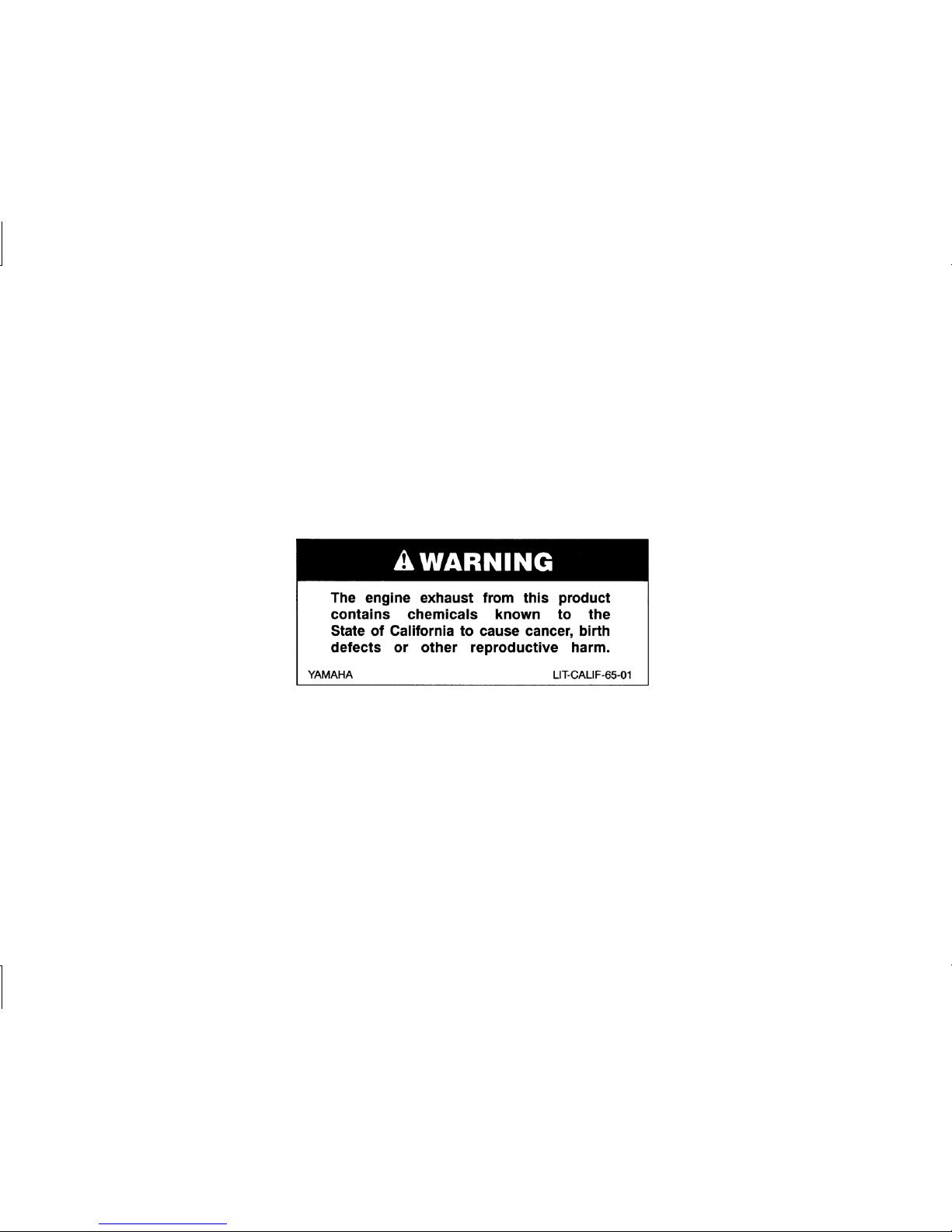
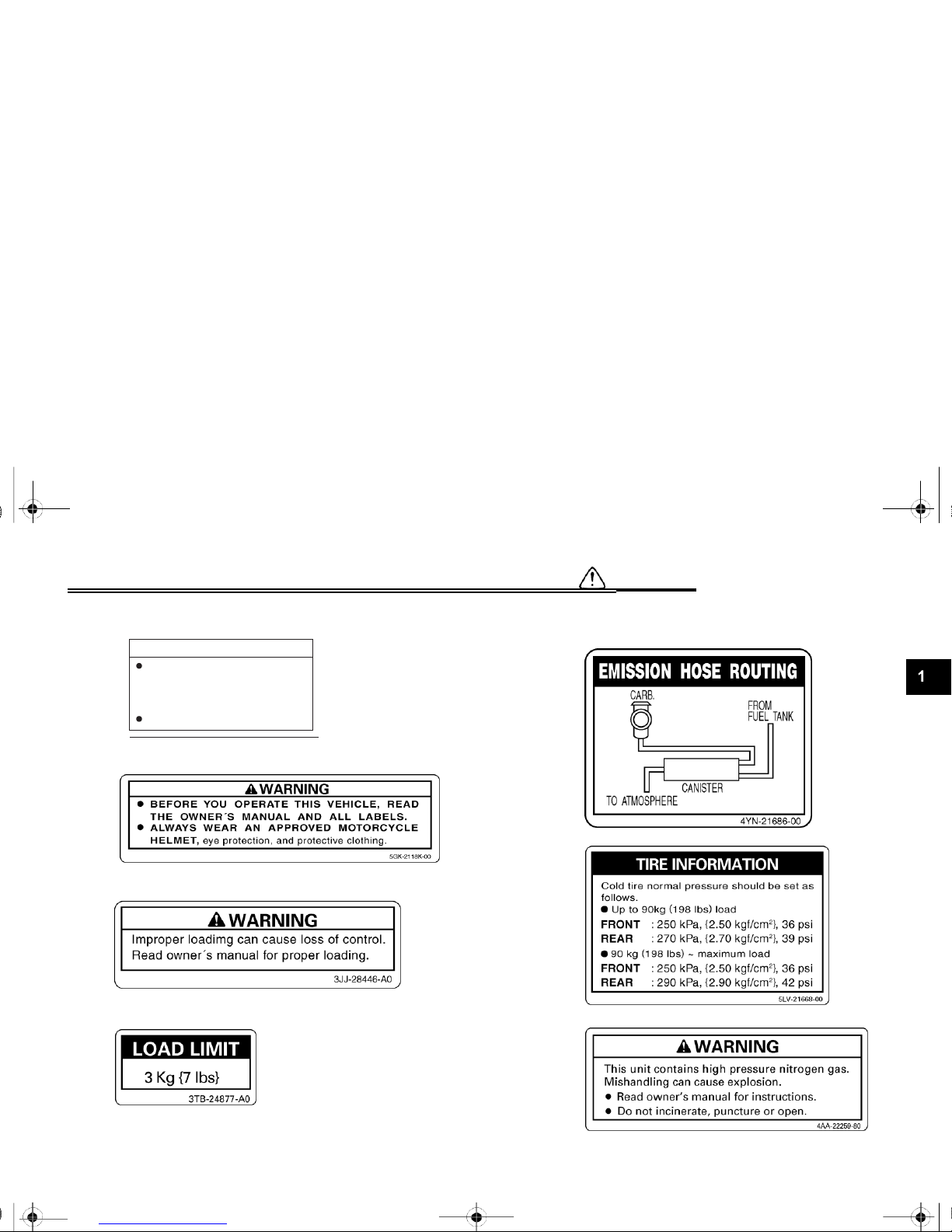
Location of important labels
Please read the following important labels carefully before operating this motorcycle.
EAU02977
1-7
U5LV12.book Page 8 Thursday, June 27, 2002 5:49 PM
SAFETY INFORMATION
1
5JW-00
(5JW-2835Y-00)
2
3
4
1-8
5
California only
6
7
Cleaning with alkaline or
acid cleaner, gasoline or
solvent will damage
windshield.
Use neutral detergent.
CAUTION
U5LV12.book Page 1 Thursday, June 27, 2002 5:49 PM
DESCRIPTION
2
Left view ..........................................................................................2-1
Right view ........................................................................................2-2
Controls and instruments..................................................................2-3
U5LV12.book Page 1 Thursday, June 27, 2002 5:49 PM
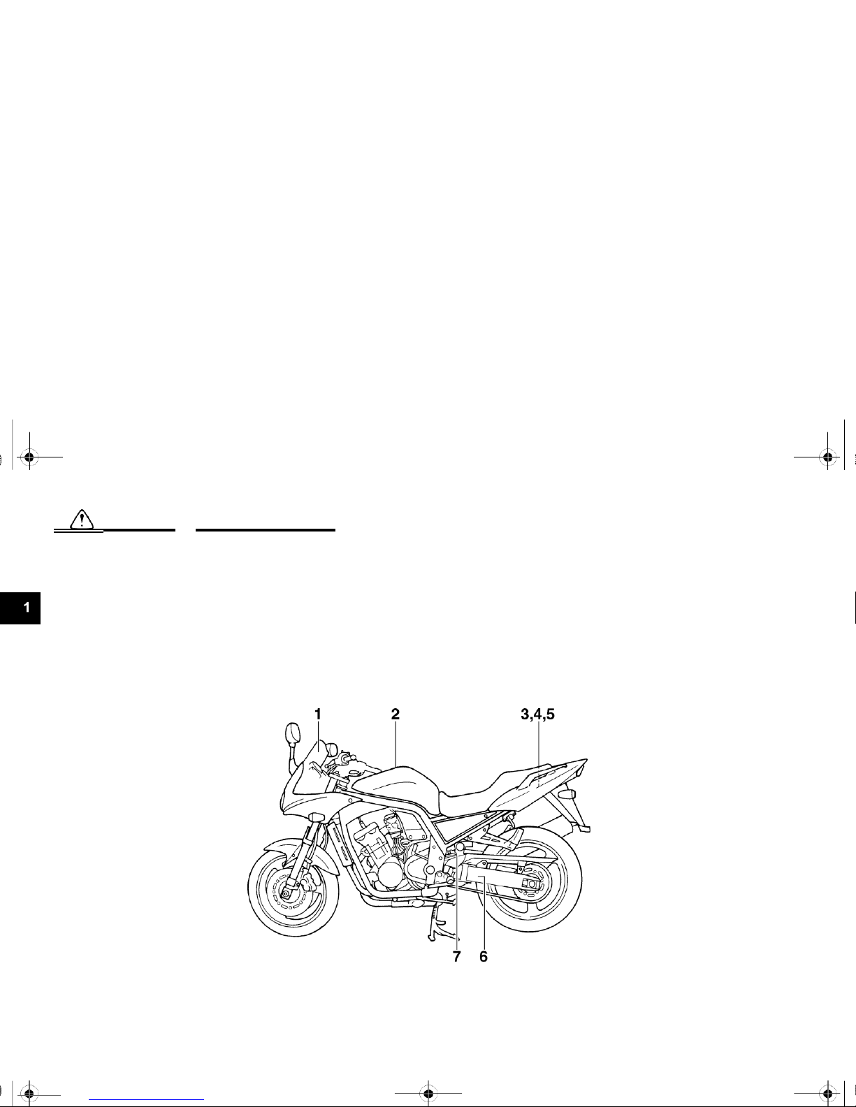
DESCRIPTION
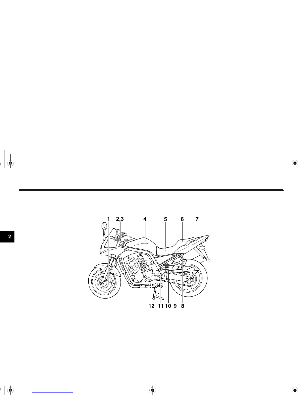
Left view
EAU00026
1. Front fork compression damping
8. Seat lock/helmet holder
(page 3-11)
force adjusting screw
(page 3-14)
9. Shock absorber assembly
2. Front fork rebound damping force
compression damping force
adjusting screw
(page 3-13)
adjusting screw
(page 3-16)
3. Front fork spring preload adjusting
10. Shock absorber assembly spring
bolt
(page 3-13)
preload adjusting ring
(page 3-15)
4. Air filter element
(page 6-19)
11. Shock absorber assembly rebound
5. Fuses
(page 6-38)
damping force adjusting knob
(page 3-15)
6.
Storage compartment (page 3-12)
7.
Grab bar
2-1
12.
Shift pedal (page 3-7)
U5LV12.book Page 2 Thursday, June 27, 2002 5:49 PM
DESCRIPTION
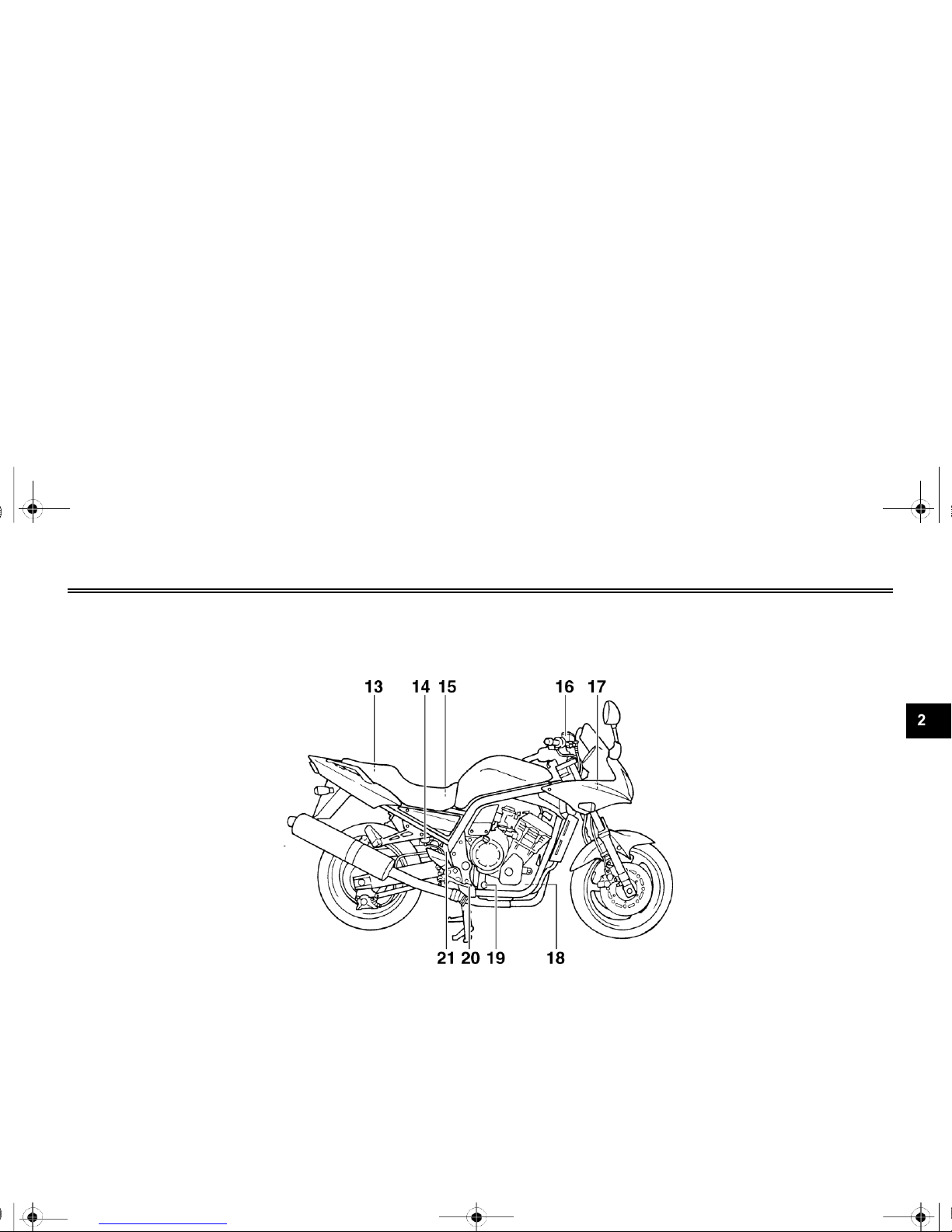
Right view
13.
Owner’s tool kit (page 6-1)
14.
Rear brake fluid reservoir (page 6-30)
15.
Battery (page 6-37)
16.
Front brake fluid reservoir (page 6-29)
17.
Radiator cap (page 6-17)
18.
Engine oil filter cartridge (page 6-13)
19.
Engine oil level check window (page 6-12)
20.
Brake pedal (page 3-8)
21.
Coolant reservoir (page 6-15)
2-2

U5LV12.book Page 3 Thursday, June 27, 2002 5:49 PM
DESCRIPTION
Controls and instruments
1.
Clutch lever (page 3-7)
2.
Left handlebar switches (page 3-6)
3.
Starter (choke) lever (page 3-10)
4.
Speedometer unit (page 3-3)
5.
Main switch/steering lock (page 3-1)
6.
Tachometer unit (page 3-4)
7.
Fuel gauge (page 3-5)
8.
Right handlebar switches (page 3-6)
9.
Brake lever (page 3-7)
10.
Throttle grip (page 6-22)
2-3
U5LV12.book Page 1 Thursday, June 27, 2002 5:49 PM
INSTRUMENT AND CONTROL FUNCTIONS
3
Main switch/steering lock..................................................................3-1
Indicator and warning lights ..............................................................3-2
Speedometer unit .............................................................................3-3
Tachometer unit................................................................................3-4
Self-diagnosis devices ......................................................................3-5
Fuel gauge .......................................................................................3-5
Handlebar switches ..........................................................................3-6
Clutch lever .............................................................................................. 3-7
Shift pedal ........................................................................................3-7
Brake lever ............................................................................................... 3-7
Brake pedal ......................................................................................3-8
Fuel tank cap ...................................................................................3-8
Fuel .................................................................................................3-9
Starter (choke) lever..............................................................................3-10
Seat ................................................................ ............................... 3-11
Helmet holder................................................................................. 3-11
Storage compartment ..................................................................... 3-12
Adjusting the front fork ................................................................... 3-12
Adjusting the shock absorber assembly .......................................... 3-14
EXUP system ................................................................................. 3-17
Sidestand ....................................................................................... 3-17
Ignition circuit cut-off system .......................................................... 3-18
WARNING
U5LV12.book Page 1 Thursday, June 27, 2002 5:49 PM
INSTRUMENT AND CONTROL FUNCTIONS
EAU00027
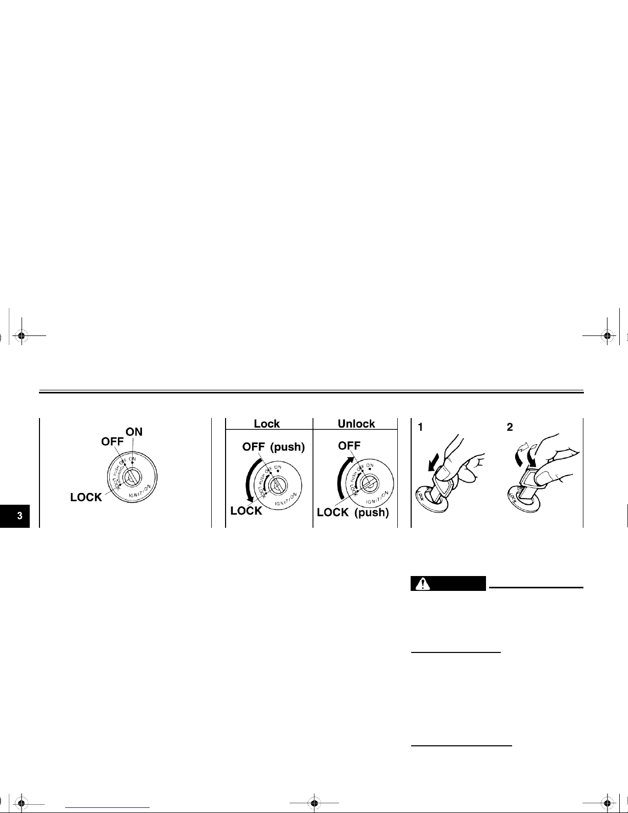
Main switch/steering lock
EAU00029
LOCK
EAU00040
1.
Push.
2.
Turn.
EW000016
The main switch/steering lock controls
the ignition and lighting systems, and is
The steering is locked, and all electrical
systems are off. The key can be
_
used to lock the steering. The various
positions are described below.
EAU00032
ON
All electrical systems are supplied with
power, and the headlight, meter lighting, taillight and position lights come
on, and the engine can be started. The
key cannot be removed.
EAU00038
OFF
All electrical systems are off. The key
can be removed.
removed.
To lock the steering
1.
Turn the handlebars all the way to the left.
2.
Push the key in from the “OFF” po- sition,
and then turn it to “LOCK” while still pushing
it.
3.
Remove the key.
To unlock the steering
Push the key in, and then turn it to “OFF” while
still pushing it.
3-1

Never turn the key to “OFF” or
“LOCK” while the motorcycle is
moving, otherwise the electrical
systems will be switched off,
which may result in loss of
control or an accident. Make
sure that the motor- cycle is
stopped before turning the key
to “OFF” or “LOCK”.
_
U5LV12.book Page 2 Thursday, June 27, 2002 5:49 PM
INSTRUMENT AND CONTROL FUNCTIONS
EAU00063
High beam indicator light “ ”
This indicator light comes on when the
high beam of the headlight is switched
on.
EAU04881
Coolant temperature warning light
“
”
This warning light comes on when the
engine overheats. When this occurs,
stop the engine immediately and allow
Oil level warning light “ ”
EAU04877
the engine to cool.
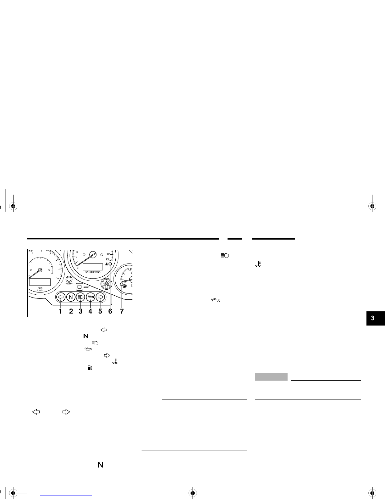
1.
Left turn signal indicator light “ ”
2.
Neutral indicator light “ ”
3.
High beam indicator light “ ”
4.
Oil level warning light “ ”
5.
Right turn signal indicator light “ ”
6.
Coolant temperature warning light “ ”
7.
Fuel level warning light “ ”
EAU03034
Indicator and warning lights
EAU04121
Turn signal indicator lights
“
” and “ ”
The corresponding indicator light flashes when the turn signal switch is
pushed to the left or right.
This warning light comes on when the
engine oil level is low.
The electrical circuit of the warning light
can be checked by turning the key to
“ON”.
If the warning light does not come on
for a few seconds, then go off, have a
Yamaha dealer check the electrical circuit.
NOTE:
Even if the oil level is sufficient, the
warning light may flicker when riding on
a slope or during sudden acceleration
or deceleration, but this is not a malfunction.
The electrical circuit of the warning light
can be checked by turning the key to
“ON”.
If the warning light does not come on
for a few seconds, then go off, have a
Yamaha dealer check the electrical circuit.
EC000002
CAUTION:
_
Do not operate the engine if it is overheated.
Neutral indicator light “ ”
EAU00061
This indicator light comes on when the
transmission is in the neutral position.

3-2
U5LV12.book Page 3 Thursday, June 27, 2002 5:49 PM
INSTRUMENT AND CONTROL FUNCTIONS
This information will enable you to plan
future fuel stops.
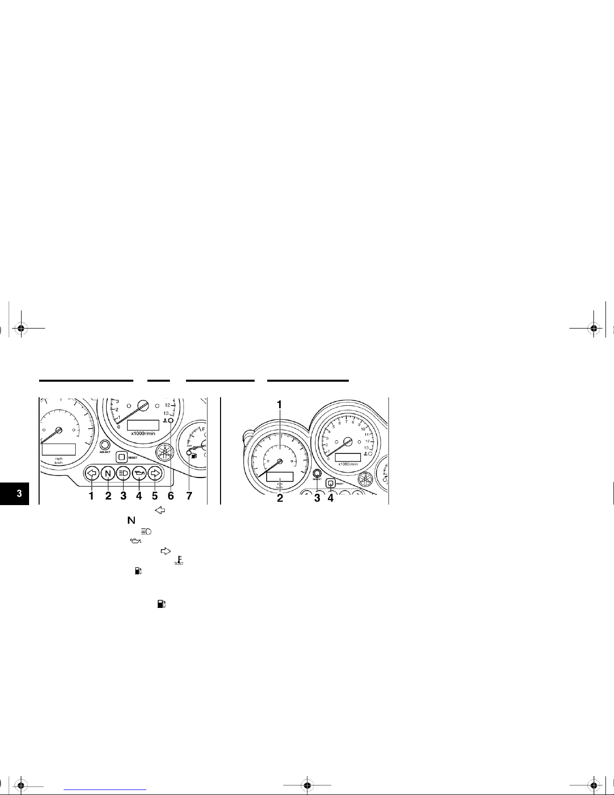
1.
Left turn signal indicator light “ ”
2.
Neutral indicator light “ ”
3.
High beam indicator light “ ”
4.
Oil level warning light “ ”
5.
Right turn signal indicator light “ ”
6.
Coolant temperature warning light “ ”
7.
Fuel level warning light “ ”
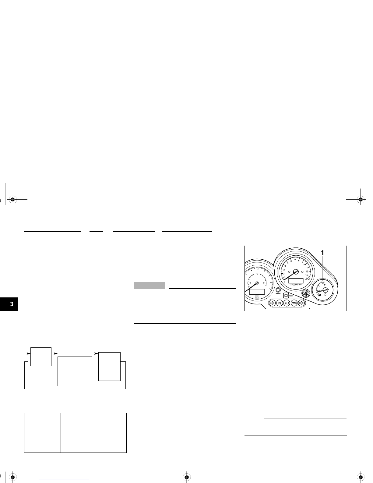
1.
Speedometer
2.
Odometer/tripmeter
3.
“SELECT” button
4.
“RESET” button
Speedometer unit
EAU04289
To set a mode
Push the “SELECT” button to change
between the odometer mode “ODO”,
and the tripmeter modes “TRIP 1” and
“TRIP 2” in the following order:
ODO TRIP 1 TRIP 2 ODO
To reset a meter
To reset either tripmeter 1 or 2 to 0.0,
select either by pushing the “SELECT”
button, and then push the “RESET”
Fuel level warning light “ ”
EAU04878
The speedometer unit is equipped with
the following:
button for at least one second.
This warning light comes on when the
fuel level drops below approximately 4
L (0.9 Imp gal, 1.1 US gal). When this
occurs, refuel as soon as possible.
The electrical circuit of the warning light
can be checked by turning the key to
“ON”.
If the warning light does not come on
for a few seconds, then go off, have a
Yamaha dealer check the electrical circuit.
●
an odometer
●
two tripmeters
When set to “ODO”, the motorcycle’s
total mileage is indicated.
When set to “TRIP 1” or “TRIP 2”, the
motorcycle’s mileage since the tripme-
ter was last reset is indicated. The tripmeters can be used together with the
fuel gauge to estimate the distance that
can be traveled on a full tank of fuel.
3-3
U5LV12.book Page 4 Thursday, June 27, 2002 5:49 PM
INSTRUMENT AND CONTROL FUNCTIONS
To set the clock:
1.
Push both the “SELECT” and
“RESET” buttons for at least two
seconds.
2.
When the hour digits start flashing,
push the “RESET” button to set
the hours.
3.
Push the “SELECT” button to
change the minutes.
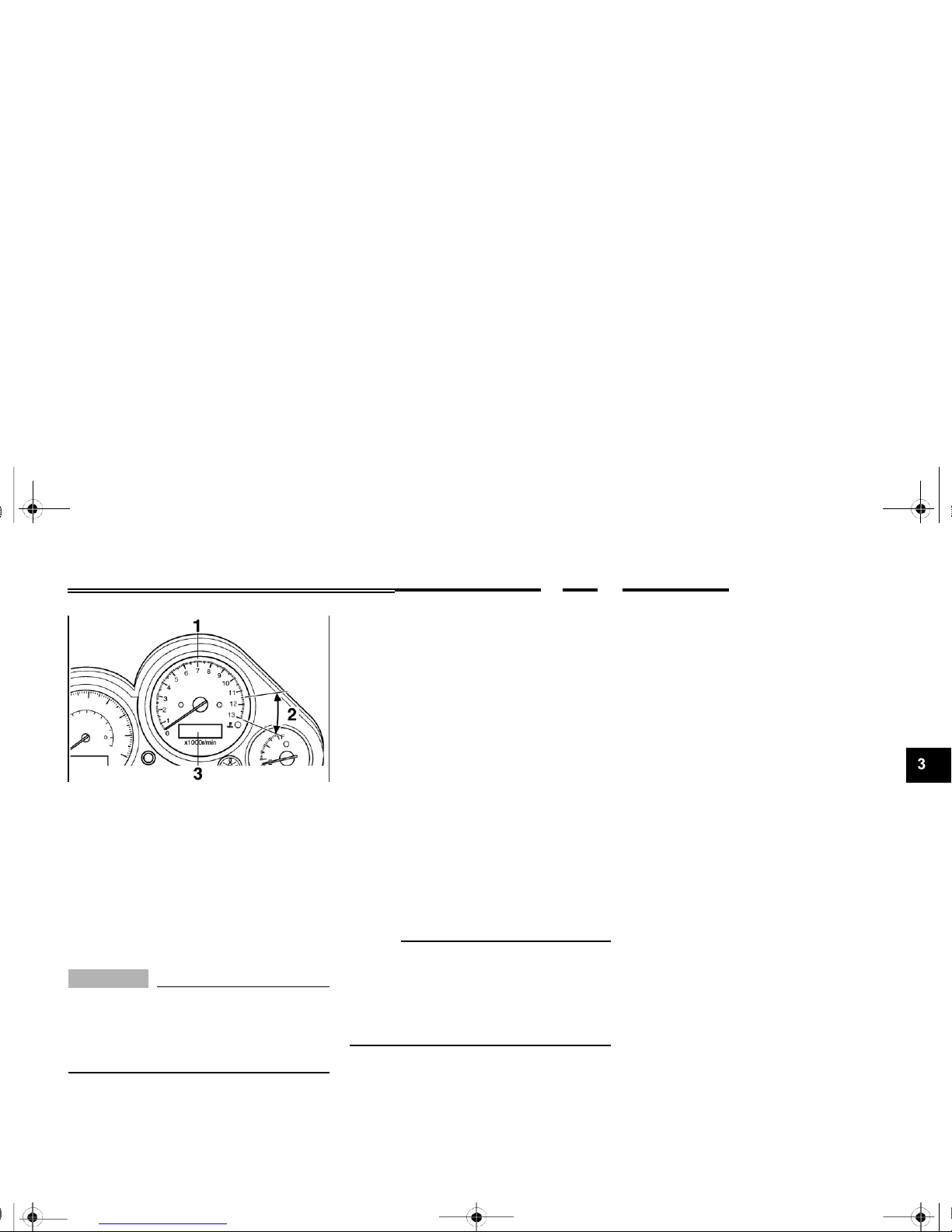
1.
Tachometer
2.
Tachometer red zone
3.
Clock
Tachometer unit
EAU03954
4.
When the minute digits start flash-
ing, push the “RESET” button to
set the minutes.
5.
Push the “SELECT” button to start
The electric tachometer allows the rider
to monitor the engine speed and keep it
within the ideal power range.
EC000003
CAUTION:
_
Do not operate the engine in the ta-
the clock.
NOTE:
After setting the clock, be sure to push
the “SELECT” button before turning the
key to “OFF”, otherwise the clock will
not be set.
chometer red zone. Red zone: 11,500 r/min and above
This tachometer unit is equipped with a
clock.
3-4
0 r/min for
Circuit-specific
number of r/min
U5LV12.book Page 5 Thursday, June 27, 2002 5:49 PM
INSTRUMENT AND CONTROL FUNCTIONS
Self-diagnosis devices
EAU04290
If the tachometer displays such an error code, note the circuit-specific num-
This model is equipped with a self-diagnosis device for the following electrical circuits:
●
throttle position sensor
●
speed sensor
●
EXUP system
●
overturn switch
If any of those circuits are defective,
the tachometer will repeatedly display
the following error code:
ber of r/min, and then have a Yamaha
dealer check the motorcycle.
EC000004
CAUTION:
_
When the tachometer displays an error code, the motorcycle should be checked as soon as possible in order to avoid engine damage.
1.
Fuel gauge
Fuel gauge
EAU00110
Current
engine
3 seconds
for 2.5 seconds
(See the table
speed for
3 seconds
below.)
Use the chart below to identify the
faulty electrical circuit.
Specific r/min
Faulty electrical circuit
3,000 r/min
Throttle position sensor
4,000 r/min
Speed sensor
7,000 r/min
EXUP system
9,000 r/min
Overturn switch
3-5
The fuel gauge indicates the amount of
fuel in the fuel tank. The needle moves
towards “E” (Empty) as the fuel level
decreases. When the needle reaches
“E”, approximately 4 L (0.9 Imp gal,
1.1
US gal) of fuel remain in the fuel
tank. If this occurs, refuel as soon as
possible.
NOTE:
Do not allow the fuel tank to empty itself completely.
U5LV12.book Page 6 Thursday, June 27, 2002 5:49 PM
INSTRUMENT AND CONTROL FUNCTIONS
Turn signal switch “ / ”
EAU03889
1.
Dimmer switch “
/
”
2.
Turn signal switch “ / ”
3.
Horn switch “ ”
EAU00118
To signal a right-hand turn, push this
switch to “ ”. To signal a left-hand
turn, push this switch to “ ”. When
released, the switch returns to the center position. To cancel the turn signal
lights, push the switch in after it has returned to the center position.
EAU00129
Horn switch “ ”
Press this switch to sound the horn.
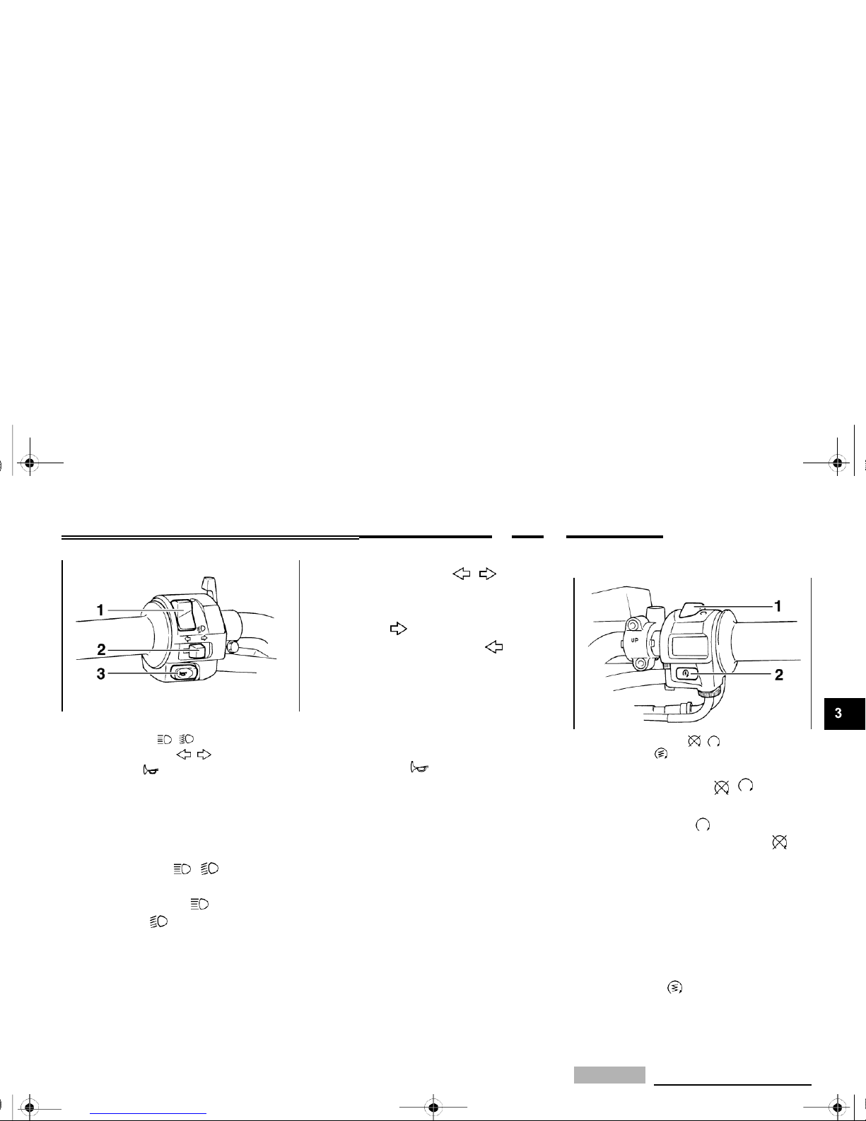
1.
Engine stop switch “ / ”
2.
Start switch “ ”
Engine stop switch “
/
”
EAU03890
Handlebar switches
Dimmer switch “ / ”
EAU03888
Set this switch to “ ” before starting
the engine. Set this switch to “ ” to
stop the engine in case of an emergen-
Set this switch to “ ” for the high
beam and to “ ” for the low beam.
cy, such as when the motorcycle overturns or when the throttle cable is
stuck.
Start switch “ ”
EAU00143
Push this switch to crank the engine
with the starter.
CAUTION:
_
EC000005
 Loading...