


FOREWORD
This Supplementary Service Manual has been prepared to introduce new service and data for the
FZS1000 (R) 2003. For complete service information procedures it is necessary to use this Supplementary Service Manual together with the following manual.
FZS1000 (N) 2001 SERVICE MANUAL: 5LV1-AE1
FZS1000 (R) 2003
SUPPLEMENTARY
SERVICE MANUAL
E2002 by Yamaha Motor Co., Ltd.
First Edition, July 2002
All rights reserved.
Any reproduction or unauthorized use
without the written permission of
Yamaha Motor Co., Ltd.
is expressly prohibited.
EAS00002
NOTICE
This manual was produced by the Yamaha Motor Company, Ltd. primarily for use by Yamaha dealers
and their qualified mechanics. It is not possible to include all the knowledge of a mechanic in one manual. Therefore, anyone who uses this book to perform maintenance and repairs on Yamaha vehicles
should have a basic understanding of mechanics and the techniques to repair these types of vehicles.
Repair and maintenance work attempted by anyone without this knowledge is likely to render the vehicle unsafe and unfit for use.
Yamaha Motor Company, Ltd. is continually striving to improve all its models. Modifications and significant changes in specifications or procedures will be forwarded to all authorized Yamaha dealers and
will appear in future editions of this manual where applicable.
NOTE:
Designs and specifications are subject to change without notice.
EAS00004
IMPORTANT INFORMATION
Particularly important information is distinguished in this manual by the following.
The Safety Alert Symbol means ATTENTION! BECOME ALERT! YOUR
SAFETY IS INVOLVED!
WARNING
CAUTION:
NOTE: A NOTE provides key information to make procedures easier or clearer.
Failure to follow WARNING instructions could result in severe injury or death
the motorcycle operator, a bystander or a person checking or repairing the motorcycle.
A CAUTION indicates special precautions that must be taken to avoid damage
to the motorcycle.
to
EAS00007
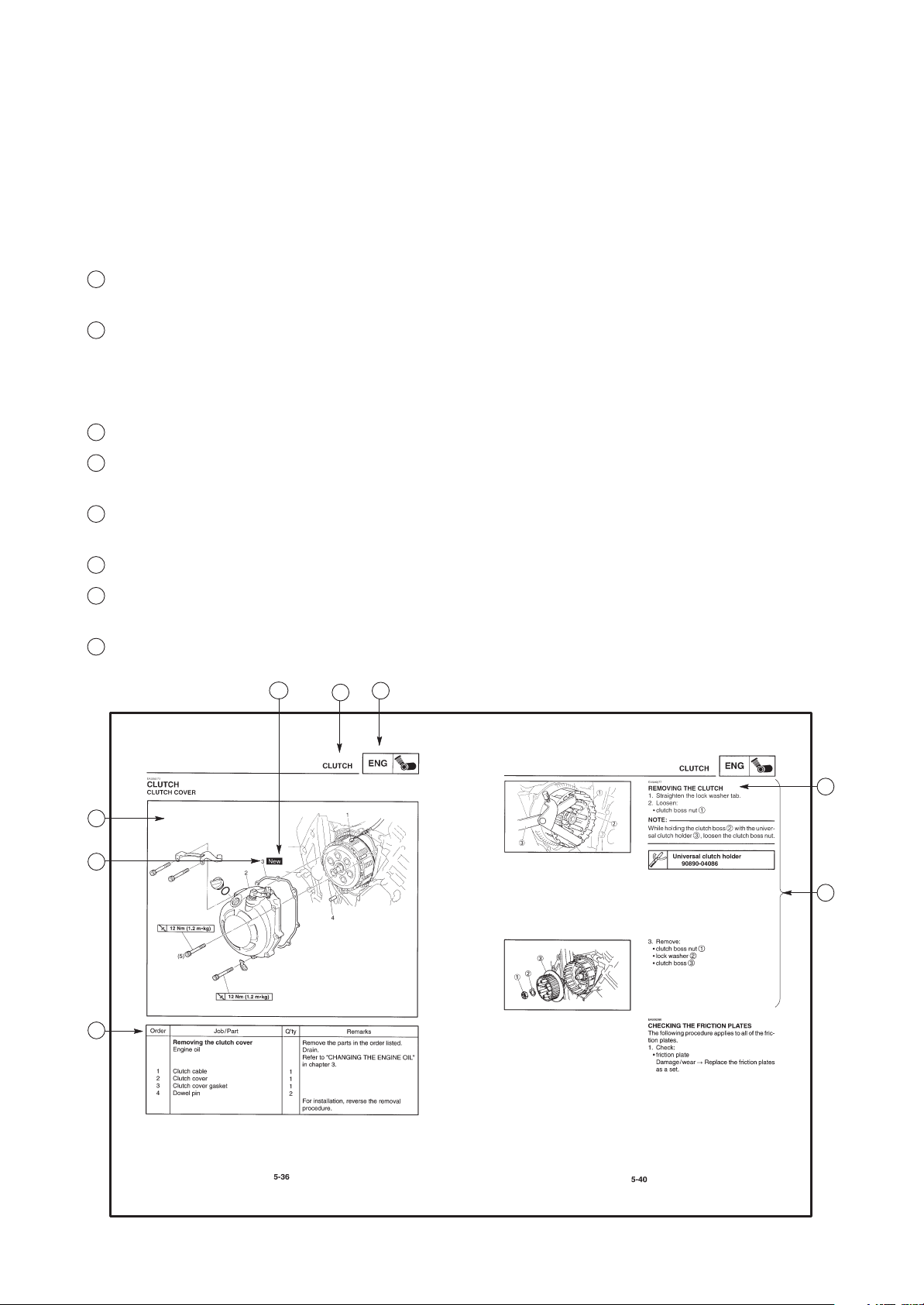
HOW TO USE THIS MANUAL
This manual is intended as a handy, easy-to-read reference book for the mechanic. Comprehensive
explanations of all installation, removal, disassembly, assembly, repair and check procedures are laid
out with the individual steps in sequential order.
1
The manual is divided into chapters. An abbreviation and symbol in the upper right corner of each
page indicate the current chapter. Refer to “SYMBOLS” on the following page.
2
Each chapter is divided into sections. The current section title is shown at the top of each page,
except in Chapter 3 (“Periodic Checks and Adjustments”), where the sub-section title(-s) appears.
(In Chapter 3, “Periodic Checks and Adjustments”, the sub-section title appears at the top of each
page, instead of the section title.)
3
Sub-section titles appear in smaller print than the section title.
4
To help identify parts and clarify procedure steps, there are exploded diagrams at the start of each
removal and disassembly section.
5
Numbers are given in the order of the jobs in the exploded diagram. A circled number indicates a
disassembly step.
6
Symbols indicate parts to be lubricated or replaced (see “SYMBOLS”).
7
A job instruction chart accompanies the exploded diagram, providing the order of jobs, names of
parts, notes in jobs, etc.
8
Jobs requiring more information (such as special tools and technical data) are described sequen-
tially.
6
4
5
7
1
2
3
8
1
GEN
INFO
3
CHK
ADJ
5
ENG
7
2
SPEC
4
CHAS
6
COOL
8
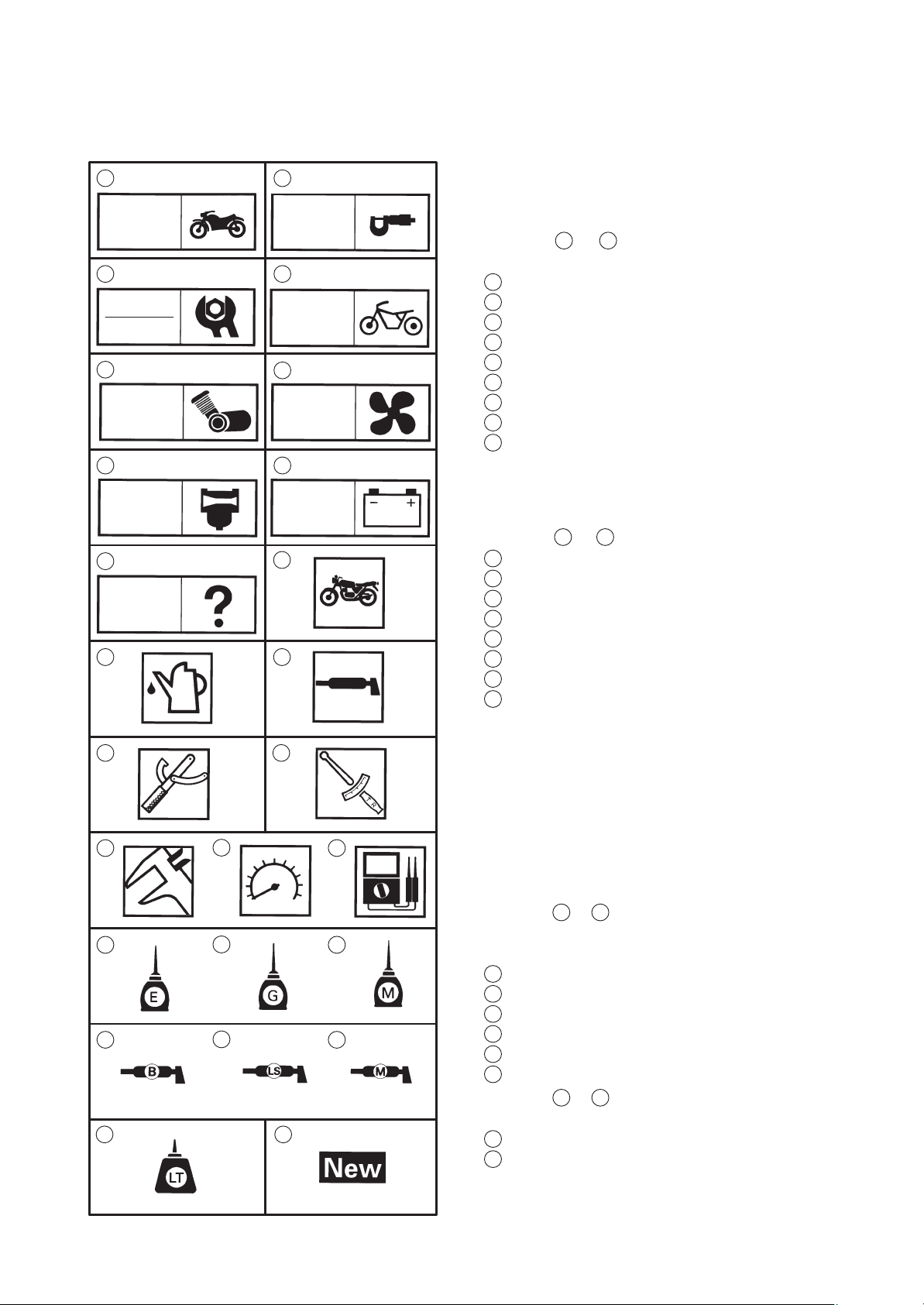
EAS00008
SYMBOLS
The following symbols are not relevant to every
vehicle.
Symbols
chapter.
General information
1
Specifications
2
Periodic checks and adjustments
3
Chassis
4
Engine
5
Cooling system
6
Carburetor(-s)
7
Electrical system
8
Troubleshooting
9
1
to 9 indicate the subject of each
CARB
9
10
TRBL
SHTG
11 12
1413
16 1715
19 2018
22
24 25
ELEC
2321
Symbols 10 to 17 indicate the following.
10
Serviceable with engine mounted
11
Filling fluid
12
Lubricant
13
Special tool
14
Tightening torque
15
Wear limit, clearance
16
Engine speed
17
Electrical data
Symbols 18 to 23 in the exploded diagrams indicate the types of lubricants and lubrication
points.
18
Engine oil
19
Gear oil
20
Molybdenum disulfide oil
21
Wheel bearing grease
22
Lithium soap base grease
23
Molybdenum disulfide grease
Symbols 24 to 25 in the exploded diagrams indicate the following:
24
Apply locking agent (LOCTITER)
25
Replace the part

CONTENTS
SPECIFICATIONS
GENERAL SPECIFICATIONS 1. . . . . . . . . . . . . . . . . . . . . . . . . . . . . . . .
ENGINE SPECIFICATIONS 1. . . . . . . . . . . . . . . . . . . . . . . . . . . . . . . . . .
CHASSIS SPECIFICATIONS 2. . . . . . . . . . . . . . . . . . . . . . . . . . . . . . . . .
CABLE ROUTING 3. . . . . . . . . . . . . . . . . . . . . . . . . . . . . . . . . . . . . . . . . .
PERIODIC CHECKS AND ADJUSTMENTS
ENGINE 14. . . . . . . . . . . . . . . . . . . . . . . . . . . . . . . . . . . . . . . . . . . . . . . . . . .
ADJUSTING THE CLUTCH CABLE FREE PLAY 14. . . . . . . . . . . .
OVERHAULING THE ENGINE
CRANKCASE 15. . . . . . . . . . . . . . . . . . . . . . . . . . . . . . . . . . . . . . . . . . . . . .
CRANKCASE 15. . . . . . . . . . . . . . . . . . . . . . . . . . . . . . . . . . . . . . . . . . .
CARBURETORS
CARBURETORS 17. . . . . . . . . . . . . . . . . . . . . . . . . . . . . . . . . . . . . . . . . . .
CHECKING AND ADJUSTING THE THROTTLE POSITION
SENSOR 17. . . . . . . . . . . . . . . . . . . . . . . . . . . . . . . . . . . . . . . . . . . . . . .
ELECTRICAL
CHECKING THE SWITCHES 20. . . . . . . . . . . . . . . . . . . . . . . . . . . . . . . .
LIGHTING SYSTEM 21. . . . . . . . . . . . . . . . . . . . . . . . . . . . . . . . . . . . . . . .
CIRCUIT DIAGRAM 21. . . . . . . . . . . . . . . . . . . . . . . . . . . . . . . . . . . . . .
TROUBLESHOOTING 22. . . . . . . . . . . . . . . . . . . . . . . . . . . . . . . . . . .
CHECKING THE LIGHTING SYSTEM 24. . . . . . . . . . . . . . . . . . . . . .
TROUBLESHOOTING
FAULTY LIGHTING OR SIGNALING SYSTEM 26. . . . . . . . . . . . . . . . .
HEADLIGHT DOES NOT LIGHT 26. . . . . . . . . . . . . . . . . . . . . . . . . . .
HEADLIGHT BULB BURNT OUT 26. . . . . . . . . . . . . . . . . . . . . . . . . .
TAIL / BRAKE LIGHT DOES NOT LIGHT 26. . . . . . . . . . . . . . . . . . . .
TAIL / BRAKE LIGHT BULB BURNT OUT 26. . . . . . . . . . . . . . . . . . .
TURN SIGNAL DOES NOT LIGHT 26. . . . . . . . . . . . . . . . . . . . . . . . .
TURN SIGNAL BLINKS SLOWLY 26. . . . . . . . . . . . . . . . . . . . . . . . . .
TURN SIGNAL REMAINS LIT 26. . . . . . . . . . . . . . . . . . . . . . . . . . . . .
TURN SIGNAL BLINKS QUICKLY 26. . . . . . . . . . . . . . . . . . . . . . . . .
HORN DOES NOT SOUND 26. . . . . . . . . . . . . . . . . . . . . . . . . . . . . . .
FZS1000 2003 WIRING DIAGRAM (EUR)
FZS1000R 2003 WIRING DIAGRAM (OCE)

GENERAL SPECIFICATIONS/ ENGINE SPECIFICATIONS
SPECIFICATIONS
GENERAL SPECIFICATIONS
Item Standard Limit
SPEC
Model code 5LVF (A) (B) (D) (DK) (E) (GB) (GR) (I)
(N) (NL) (S) (SF) (CH) (P)
5LVG (D)
5LVH (F)
5LVJ (AUS)
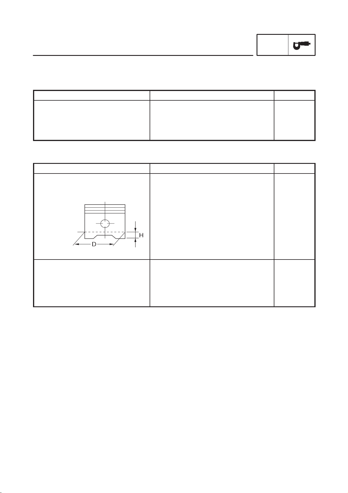
ENGINE SPECIFICATIONS
Item Standard Limit
Piston
Piston-to-cylinder clearance
Diameter D
Height H
Carburetors
ID mark
0.010 X 0.035 mm
73.955 X 73.970 mm
5 mm
5LV1 00 (A) (B) (D) (DK) (E) (GB) (GR)
(I) (N) (NL) (S) (SF) (CH) (P)
(AUS)
5LV3 20 (D)
5LV2 10 (F)
SSS
SSS
SSS
SSS
0.12 mm
SSS
SSS
SSS
SSS
SSS
–1–
CHASSIS SPECIFICATIONS
Item Standard Limit
Front suspension
Spring
Free length
Spacer length
Installed length
Spring rate (K1)
Spring rate (K2)
Spring stroke (K1)
Spring stroke (K2)
Optional spring available
Fork oil
Recommended oil
Quantity (each front fork leg)
Level (from the top of the inner
tube, with the inner tube fully
compressed, and without the
fork spring)
CHASSIS SPECIFICATIONS
344.0 mm
78.5 mm
320.0 mm
7.8 N/ mm (0.8 kg /mm)
11.8 N/ mm (1.2 kg/ mm)
0 X 64 mm
64 X 140 mm
No
Suspension oil “01” or equivalent
435 cm
140 mm
3
SPEC
SSS
SSS
SSS
SSS
SSS
SSS
SSS
SSS
SSS
SSS
SSS
–2–
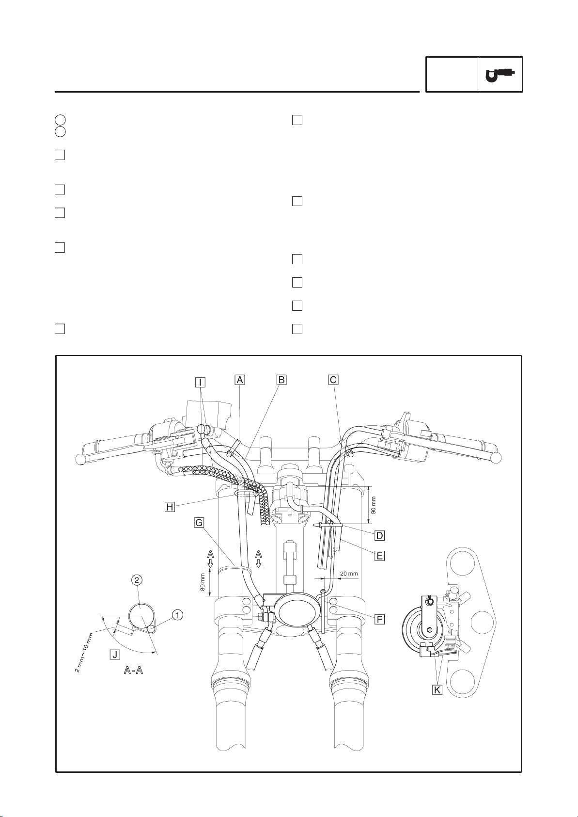
CABLE ROUTING
1 Brake hose
2 Front fork
A Fasten the right handlebar switch lead to the han-
dlebar with a plastic band. Point the end of clamp to
the downward.
B Route the right handlebar switch lead by the right
side of the wire guide behind the throttle cable.
C Fasten the left handlebar switch lead to the handle-
bar with a plastic band. Point the end of clamp to the
downward.
D Fasten the left handlebar switch lead, main switch
lead, clutch cable and starter cable with a plastic
band. Clamp beneath the horn lead branching position. Do not fasten the horn lead. Direct the end of
clamp to the rear inner side of vehicle.
Clamp it at 90 mm below the bottom end of the upper bracket.
E Route the main switch lead front and left side the
another leads.
CABLE ROUTING
F Pass the horn leads from the outside of vehicle to
the inner side and clamp it to the under-bracket.
Point the tip of clamp to the front of vehicle. There
should be no slack with the lead between horn and
clamp.
Clamp it at the position of 20 mm from the inner side
of the inner tube.
G Clamp the brake hose to the inner tube. Cut the sur-
plus part of clamp tip leaving 2 to 10 mm and point
the tip of clamp to the front of vehicle.
Clamp it at 80 mm from the top end of the under
bracket.
H Route the brake hose through the brake hose
guide.
I Route the throttle cable 1 and 2 behind the brake
hose and pass it by the left side of wire guide.
J Position the remained part of clamp tip within this
range.
K Direct the horn lead coupler to the rear.
SPEC
–3–
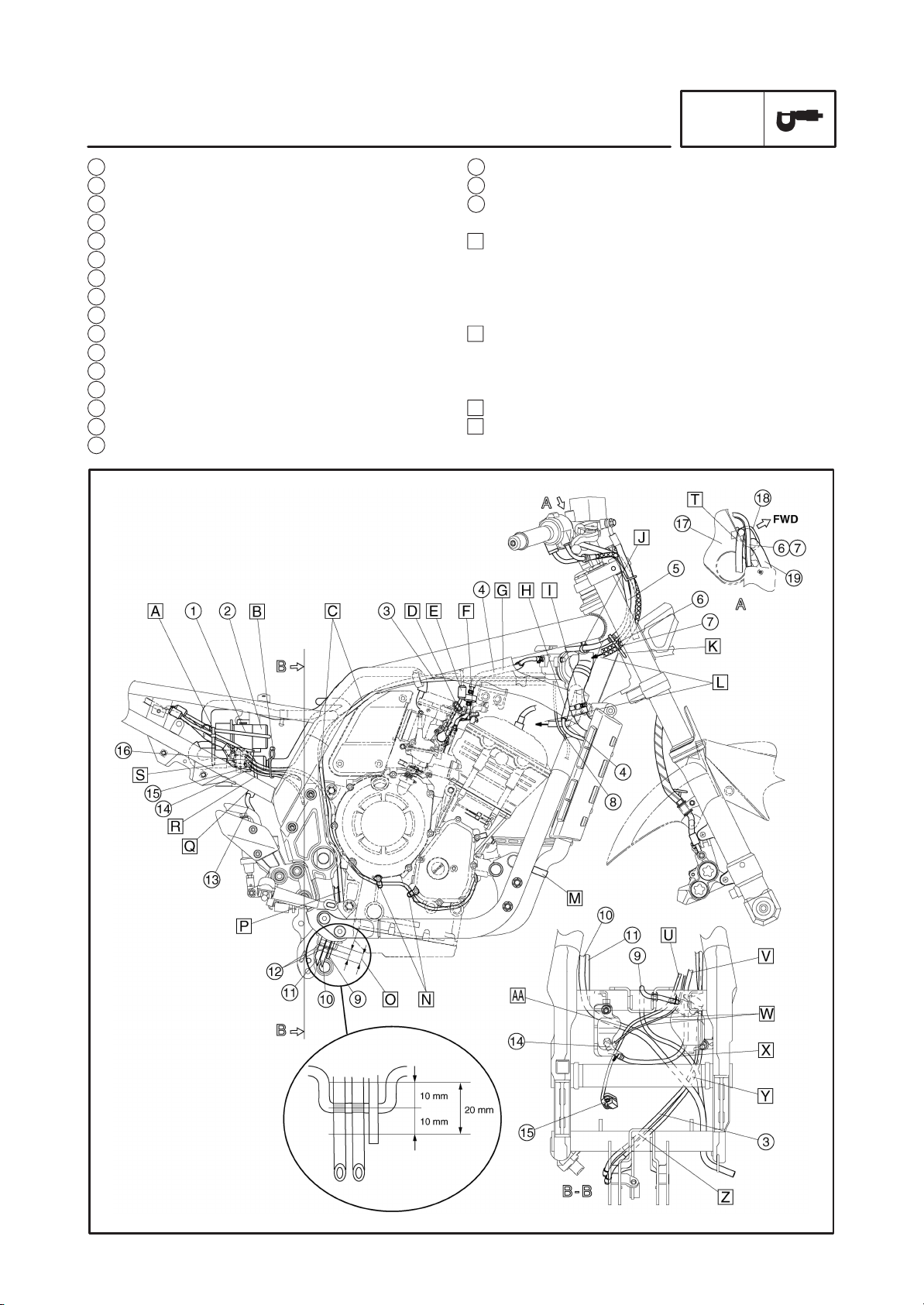
CABLE ROUTING
SPEC
1 Fuel pump lead
2 Fuel pump
3 EXUP cable
4 Carburetor heater hose
5 Right handlebar switch lead
6 Throttle cable 2
7 Throttle cable 1
8 Radiator fan motor lead
9 Coolant reservoir tank over flow hose
10 Fuel tank drain hose
11 Fuel tank breather hose
12 White paint mark
13 Rear brake light switch lead
14 Neutral switch lead
15 Speed sensor lead
16 Pickup coil lead
17 Handlebar upper bracket
18 Brake hose guide
19 Front brake hose
A Fasten the fuel pump lead, pickup coil lead, neutral
switch lead, speed sensor lead, rear brake light
switch lead and fuel pump with a plastic clamp.
Pass the clamp tip between the frame and rear
fender and point it to the downward.
B Fasten the fuel hose, pickup coil lead, neutral switch
lead and speed sensor lead with a plastic clamp under the fuel hose. Place the fitting part on the up-
ward.
C Put the EXUP cable into the air box cover.
D Clamp the throttle position sensor lead to the carbu-
retor with a steel clamp.
–4–
 Loading...