


OWNER’S MANUAL
LIT-11626-16-33
FZS1000R
FZS1000RC
FZS1000SR
FZS1000SRC
5LV-28199-12
EAU03438
U5LV12.book Page 1 Thursday, June 27, 2002 5:49 PM
EAU00002
INTRODUCTION
Congratulations on your purchase of the Yamaha FZS1000/FZS1000S. This model
is the result of Yamaha’s vast experience in the production of fine sporting, touring,
and pacesetting racing machines. It represents the high degree of craftsmanship and
reliability that have made Yamaha a leader in these fields.
This manual will give you an understanding of the operation, inspection, and basic
maintenance of this motorcycle. If you have any questions concerning the operation
or maintenance of your motorcycle, please consult a Yamaha dealer.
The design and manufacture of this Yamaha motorcycle fully comply with the emissions standards for clean air applicable at the date of manufacture. Yamaha has met
these standards without reducing the performance or economy of operation of the
motorcycle. To maintain these high standards, it is important that you and your
Yamaha dealer pay close attention to the recommended maintenance schedules and
operating instructions contained within this manual.
U5LV12.book Page 1 Thursday, June 27, 2002 5:49 PM
IMPORTANT MANUAL INFORMATION
Particularly important information is distinguished in this manual by the following notations:
EAU00003
NOTE:
●
This manual should be considered a permanent part of this motorcycle and should remain
with it even if the motorcycle is subsequently sold.
●
Yamaha continually seeks advancements in product design and quality. Therefore, while
this manual contains the most current product information available at the time of printing,
there may be minor discrepancies between your motorcycle and this manual. If you have
any questions concerning this manual, please consult your Yamaha dealer.
The Safety Alert Symbol means ATTENTION! BECOME ALERT! YOUR SAFETY IS
INVOLVED!
Failure to follow WARNING instructions could result in severe injury or death to the
motorcycle operator, a bystander or a person inspecting or repairing the motorcycle.
A CAUTION indicates special precautions that must be taken to avoid damage to the
motorcycle.
CAUTION:
NOTE: A NOTE provides key information to make procedures easier or clearer.
U5LV12.book Page 2 Thursday, June 27, 2002 5:49 PM
IMPORTANT MANUAL INFORMATION
EW000000
_
PLEASE READ THIS MANUAL AND THE “YOU AND YOUR MOTORCYCLE: RIDING
TIPS” BOOKLET CAREFULLY AND COMPLETELY BEFORE OPERATING THIS MOTOR-
CYCLE. DO NOT ATTEMPT TO OPERATE THIS MOTORCYCLE UNTIL YOU HAVE ATTAINED ADEQUATE KNOWLEDGE OF ITS CONTROLS AND OPERATING FEATURES
AND UNTIL YOU HAVE BEEN TRAINED IN SAFE AND PROPER RIDING TECHNIQUES.
REGULAR INSPECTIONS AND CAREFUL MAINTENANCE, ALONG WITH GOOD RIDING
SKILLS, WILL ENSURE THAT YOU SAFELY ENJOY THE CAPABILITIES AND THE RELIABILITY OF THIS MOTORCYCLE.
_
WARNING
U5LV12.book Page 3 Thursday, June 27, 2002 5:49 PM
IMPORTANT MANUAL INFORMATION
AFFIX DEALER
LABEL HERE
EAU04247
FZS1000R/FZS1000RC/FZS1000SR/FZS1000SRC
OWNER’S MANUAL
©2002 by Yamaha Motor Corporation, U.S.A.
1st edition, May 2002
All rights reserved.
Any reprinting or unauthorized use
without the written permission of
Yamaha Motor Corporation, U.S.A.
is expressly prohibited.
Printed in Japan.
P/N LIT-11626-16-33
U5LV12.book Page 1 Thursday, June 27, 2002 5:49 PM
EAU00009
TABLE OF CONTENTS
1 SAFETY INFORMATION
1
2 DESCRIPTION
2
3 INSTRUMENT AND CONTROL FUNCTIONS
3
4 PRE-OPERATION CHECKS
4
5 OPERATION AND IMPORTANT RIDING POINTS
5
6 PERIODIC MAINTENANCE AND MINOR REPAIR
6
7 MOTORCYCLE CARE AND STORAGE
7
8 SPECIFICATIONS
8
9 CONSUMER INFORMATION
9
INDEX

U5LV12.book Page 1 Thursday, June 27, 2002 5:49 PM
SAFETY INFORMATION
1
Safe riding........................................................................................1-1
Protective apparel ............................................................................1-3
Modifications ....................................................................................1-3
Loading and accessories ..................................................................1-3
Gasoline and exhaust gas ................................................................1-5
Location of important labels ..............................................................1-7
U5LV12.book Page 1 Thursday, June 27, 2002 5:49 PM
MOTORCYCLES ARE SINGLE TRACK VEHICLES. THEIR SAFE USE AND OPERATION ARE
DEPENDENT UPON THE USE OF PROPER RIDING TECHNIQUES AS WELL AS THE EXPERTISE
OF THE OPERATOR. EVERY OPERATOR SHOULD KNOW THE FOLLOWING REQUIREMENTS
BEFORE RIDING THIS MOTORCYCLE.
HE OR SHE SHOULD:
1.
OBTAIN THOROUGH INSTRUCTIONS FROM A COMPETENT SOURCE ON ALL ASPECTS OF
MOTORCYCLE OPERATION.
2.
OBSERVE THE WARNINGS AND MAINTENANCE REQUIREMENTS IN THE OWNER’S
MANUAL.
3.
OBTAIN QUALIFIED TRAINING IN SAFE AND PROPER RIDING TECHNIQUES.
4.
OBTAIN PROFESSIONAL TECHNICAL SERVICE AS INDICATED BY THE OWNER’S MANUAL
AND/OR WHEN MADE NECESSARY BY MECHANICAL CONDITIONS.
Safe riding
1.
Always make pre-operation checks. Careful checks may help prevent an accident.
2.
This motorcycle is designed to carry the operator and a passenger.
3.
The failure of motorists to detect and recognize motorcycles in traffic is the predominating cause of
automobile/motorcycle accidents. Many accidents have been caused by an automobile driver who
did not see the motorcycle. Making yourself conspicuous appears to be very effective in reducing the
chance of this type of accident.
Therefore:
a.
Wear a brightly colored jacket.
b.
Use extra caution when you are approaching and passing through intersections, since intersections are the most likely places for motorcycle accidents to occur.
c.
Ride where other motorists can see you. Avoid riding in another motorist’s blind spot.
1-1
SAFETY INFORMATION
EAU00014
U5LV12.book Page 2 Thursday, June 27, 2002 5:49 PM
SAFETY INFORMATION
4.
Many accidents involve inexperienced operators. In fact, many operators who have been involved in
accidents do not even have a current motorcycle license.
a.
Make sure that you are qualified and that you only lend your motorcycle to other qualified
operators.
b.
Know your skills and limits. Staying within your limits may help you to avoid an accident.
c.
We recommend that you practice riding your motorcycle where there is no traffic until you have
become thoroughly familiar with the motorcycle and all of its controls.
5.
Many accidents have been caused by error of the motorcycle operator. A typical error made by the
operator is veering wide on a turn due to EXCESSIVE SPEED or undercornering (insufficient lean
angle for the speed).
a.
Always obey the speed limit and never travel faster than warranted by road and traffic conditions.
b.
Always signal before turning or changing lanes. Make sure that other motorists can see you.
6.
The posture of the operator and passenger is important for proper control.
a.
The operator should keep both hands on the handlebar and both feet on the operator footrests
during operation to maintain control of the motorcycle.
b.
The passenger should always hold onto the operator, the seat strap or grab bar, if equipped, with
both hands and keep both feet on the passenger footrests.
c.
Never carry a passenger unless he or she can firmly place both feet on the passenger footrests.
7.
Never ride under the influence of alcohol or other drugs.
8.
This motorcycle is designed for on-road use only. It is not suitable for off-road use.
1-2

U5LV12.book Page 3 Thursday, June 27, 2002 5:49 PM
SAFETY INFORMATION
Protective apparel
The majority of fatalities from motorcycle accidents are the result of head injuries. The use of a safety
helmet is the single most critical factor in the prevention or reduction of head injuries.
1.
Always wear an approved helmet.
2.
Wear a face shield or goggles. Wind in your unprotected eyes could contribute to an impairment of vision that could delay seeing a hazard.
3.
The use of a jacket, heavy boots, trousers, gloves, etc., is effective in preventing or reducing abrasions or lacerations.
4.
Never wear loose-fitting clothes, otherwise they could catch on the control levers, footrests, or wheels
and cause injury or an accident.
5.
Never touch the engine or exhaust system during or after operation. They become very hot and can
cause burns. Always wear protective clothing that covers your legs, ankles, and feet.
6.
A passenger should also observe the above precautions.
Modifications
Modifications made to this motorcycle not approved by Yamaha, or the removal of original equipment,
may render the motorcycle unsafe for use and may cause severe personal injury. Modifications may
also make your motorcycle illegal to use.
Loading and accessories
Adding accessories or cargo to your motorcycle can adversely affect stability and handling if the weight
distribution of the motorcycle is changed. To avoid the possibility of an accident, use extreme caution
when adding cargo or accessories to your motorcycle. Use extra care when riding a motorcycle that
has added cargo or accessories. Here are some general guidelines to follow if loading cargo or adding
accessories to your motorcycle:
1-3

U5LV12.book Page 4 Thursday, June 27, 2002 5:49 PM
SAFETY INFORMATION
Loading
The total weight of the operator, passenger, accessories and cargo must not exceed the maximum
load limit of FZS1000, FZS1000S: 189 kg (417 lb) / FZS1000C, FZS1000SC: 188 kg (415 lb). When
loading within this weight limit, keep the following in mind:
1.
Cargo and accessory weight should be kept as low and close to the motorcycle as possible. Make
sure to distribute the weight as evenly as possible on both sides of the motorcycle to minimize imbalance or instability.
2.
Shifting weights can create a sudden imbalance. Make sure that accessories and cargo are securely
attached to the motorcycle before riding. Check accessory mounts and cargo restraints frequently.
3.
Never attach any large or heavy items to the handlebar, front fork, or front fender. These items, including such items as sleeping bags, duffel bags, or tents, can create unstable handling or a slow
steering response.
Accessories
Genuine Yamaha accessories have been specifically designed for use on this motorcycle. Since
Yamaha cannot test all other accessories that may be available, you must personally be responsible
for the proper selection, installation and use of non-Yamaha accessories. Use extreme caution when
selecting and installing any accessories.
Keep the following guidelines in mind, as well as those provided under “Loading” when mounting acces-
sories.
1.
Never install accessories or carry cargo that would impair the performance of your motorcycle. Carefully inspect the accessory before using it to make sure that it does not in any way reduce ground
clearance or cornering clearance, limit suspension travel, steering travel or control operation, or obscure lights or reflectors.
1-4
U5LV12.book Page 5 Thursday, June 27, 2002 5:49 PM
SAFETY INFORMATION
a.
Accessories fitted to the handlebar or the front fork area can create instability due to improper
weight distribution or aerodynamic changes. If accessories are added to the handlebar or front
fork area, they must be as lightweight as possible and should be kept to a minimum.
b.
Bulky or large accessories may seriously affect the stability of the motorcycle due to aerodynamic
effects. Wind may attempt to lift the motorcycle, or the motorcycle may become unstable in cross
winds. These accessories may also cause instability when passing or being passed by large
vehicles.
c.
Certain accessories can displace the operator from his or her normal riding position. This improper position limits the freedom of movement of the operator and may limit control ability, therefore,
such accessories are not recommended.
2.
Use caution when adding electrical accessories. If electrical accessories exceed the capacity of the
motorcycle’s electrical system, an electric failure could result, which could cause a dangerous loss of
lights or engine power.
Gasoline and exhaust gas
1.
GASOLINE IS HIGHLY FLAMMABLE:
a.
Always turn the engine off when refueling.
b.
Take care not to spill any gasoline on the engine or exhaust system when refueling.
c.
Never refuel while smoking or in the vicinity of an open flame.
2.
Never start the engine or let it run for any length of time in a closed area. The exhaust fumes are poisonous and may cause loss of consciousness and death within a short time. Always operate your
motorcycle in an area that has adequate ventilation.
3.
Always turn the engine off before leaving the motorcycle unattended and remove the key from the
main switch. When parking the motorcycle, note the following:
1-5

U5LV12.book Page 6 Thursday, June 27, 2002 5:49 PM
SAFETY INFORMATION
a.
The engine and exhaust system may be hot, therefore, park the motorcycle in a place where pedestrians or children are not likely to touch these hot areas.
b.
Do not park the motorcycle on a slope or soft ground, otherwise it may fall over.
c.
Do not park the motorcycle near a flammable source (e.g., a kerosene heater, or near an open
flame), otherwise it could catch fire.
4.
When transporting the motorcycle in another vehicle, make sure that it is kept upright. If the motorcycle should lean over, gasoline may leak out of the carburetor or fuel tank.
5.
If you should swallow any gasoline, inhale a lot of gasoline vapor, or allow gasoline to get into your
eyes, see your doctor immediately. If any gasoline spills on your skin or clothing, immediately wash
the affected area with soap and water and change your clothes.
1-6
U5LV12.book Page 7 Thursday, June 27, 2002 5:49 PM
SAFETY INFORMATION
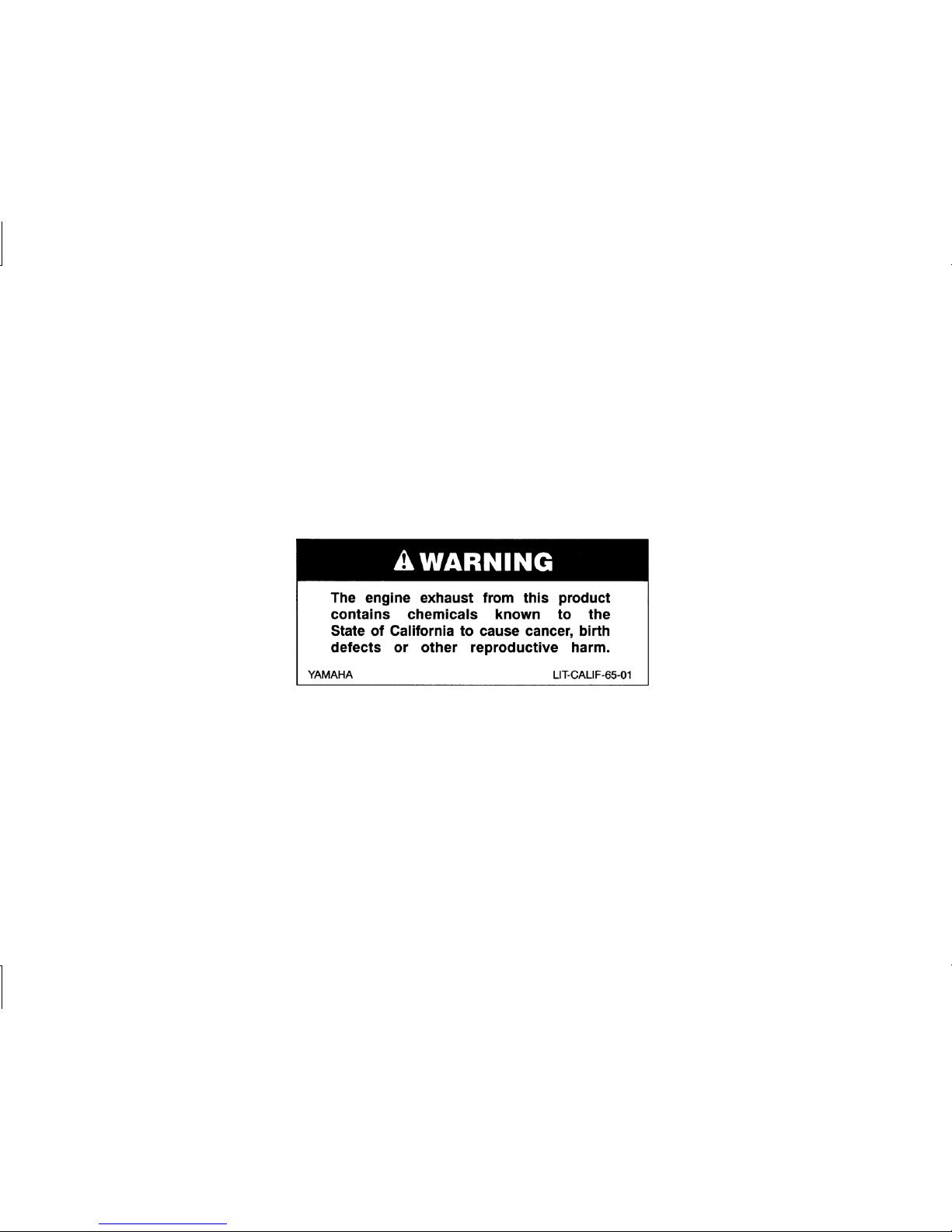
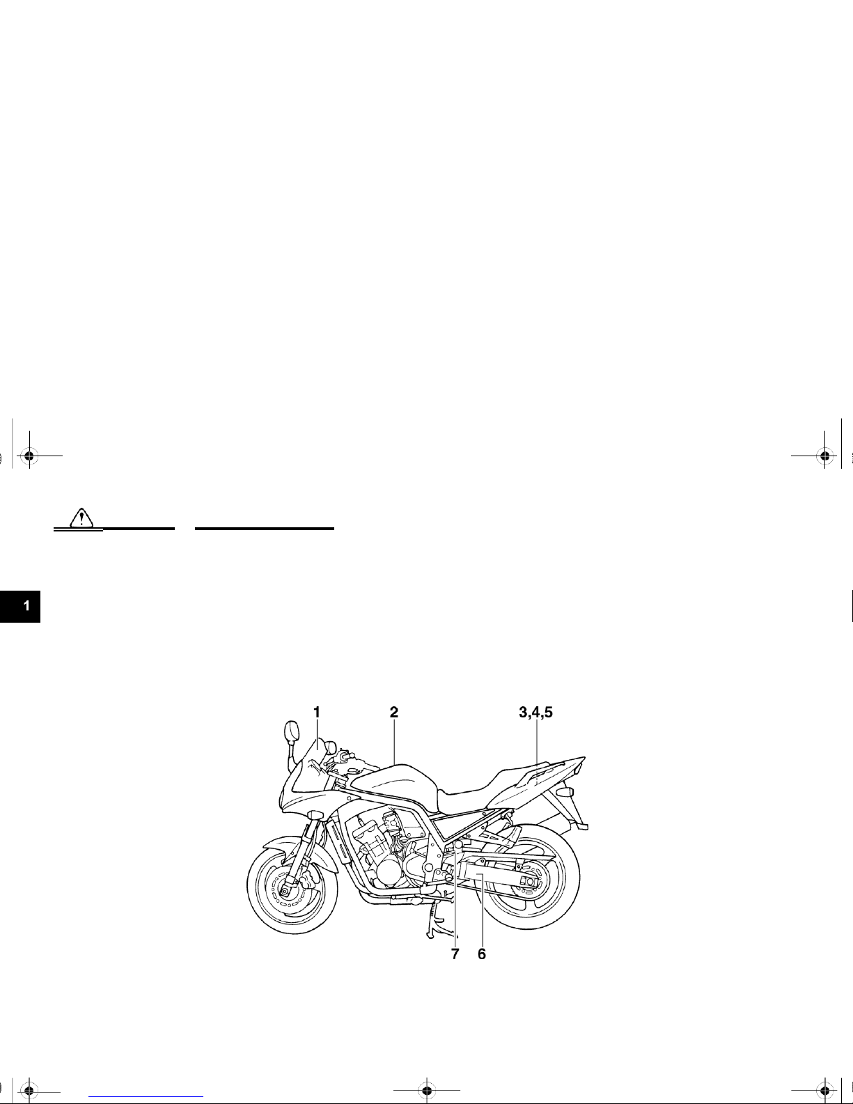
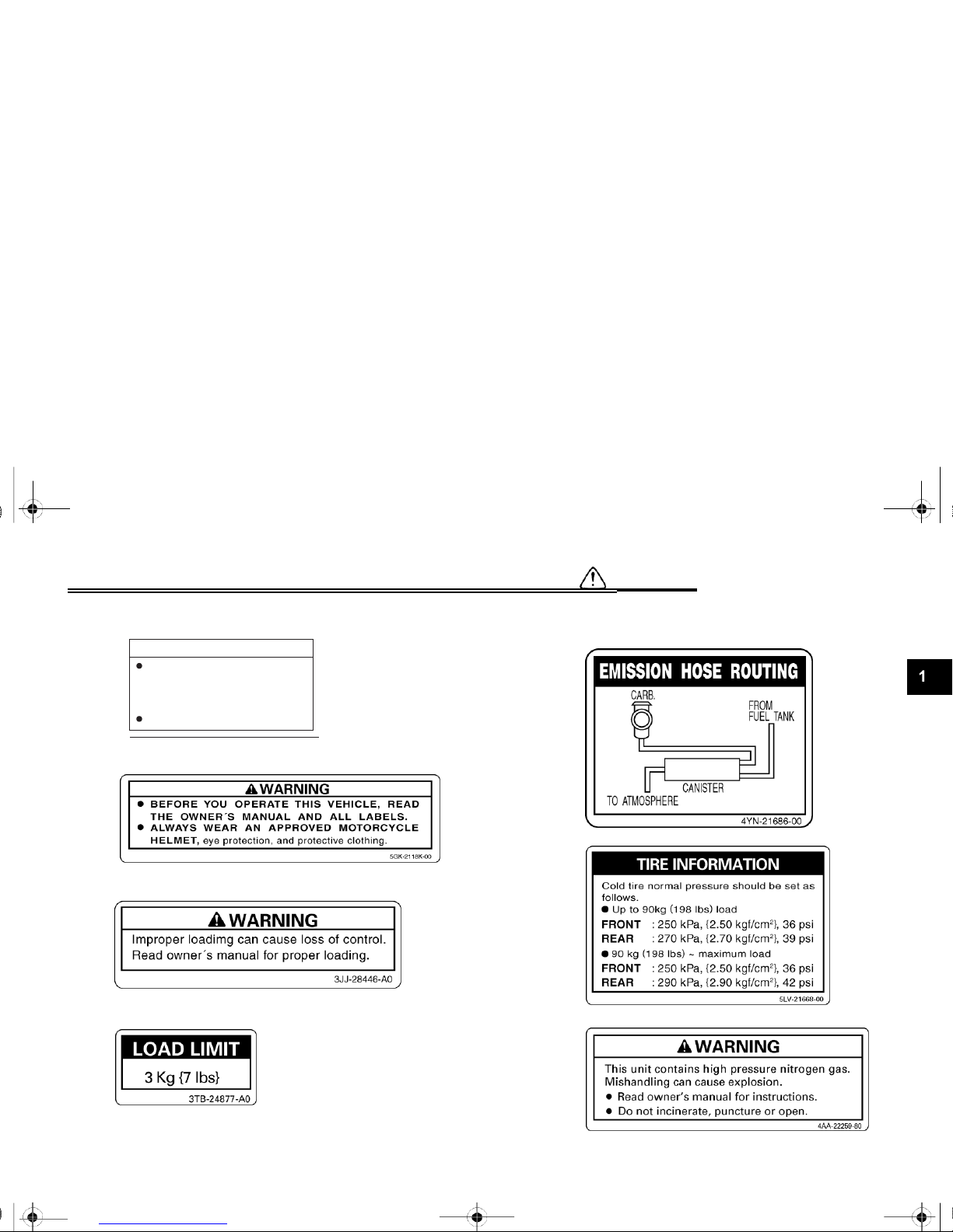
Location of important labels
Please read the following important labels carefully before operating this motorcycle.
EAU02977
1-7
U5LV12.book Page 8 Thursday, June 27, 2002 5:49 PM
SAFETY INFORMATION
1
5JW-00
(5JW-2835Y-00)
2
3
4
1-8
5
California only
6
7
Cleaning with alkaline or
acid cleaner, gasoline or
solvent will damage
windshield.
Use neutral detergent.
CAUTION
U5LV12.book Page 1 Thursday, June 27, 2002 5:49 PM
DESCRIPTION
2
Left view ..........................................................................................2-1
Right view ........................................................................................2-2
Controls and instruments..................................................................2-3
U5LV12.book Page 1 Thursday, June 27, 2002 5:49 PM
DESCRIPTION
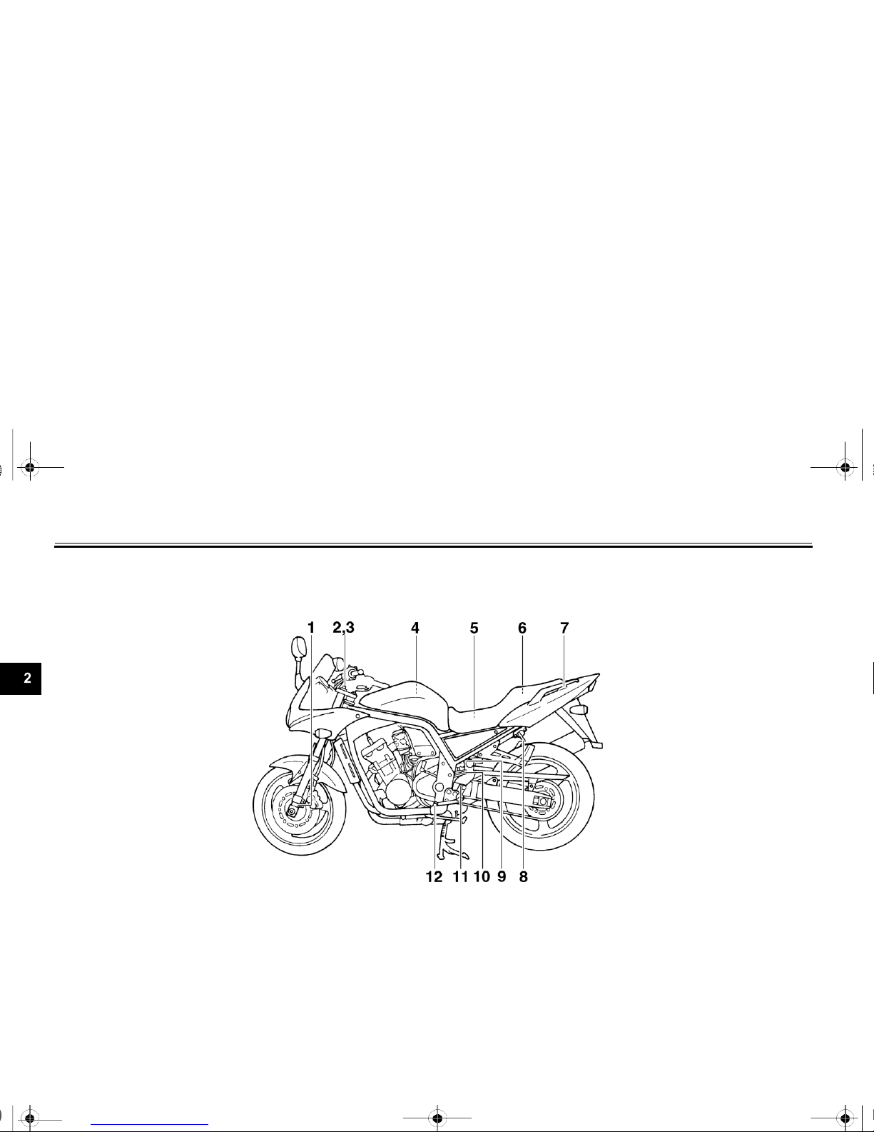
Left view
EAU00026
1. Front fork compression damping
8. Seat lock/helmet holder
(page 3-11)
force adjusting screw
(page 3-14)
9. Shock absorber assembly
2. Front fork rebound damping force
compression damping force
adjusting screw
(page 3-13)
adjusting screw
(page 3-16)
3. Front fork spring preload adjusting
10. Shock absorber assembly spring
bolt
(page 3-13)
preload adjusting ring
(page 3-15)
4. Air filter element
(page 6-19)
11. Shock absorber assembly rebound
5. Fuses
(page 6-38)
damping force adjusting knob
(page 3-15)
6.
Storage compartment (page 3-12)
7.
Grab bar
2-1
12.
Shift pedal (page 3-7)
U5LV12.book Page 2 Thursday, June 27, 2002 5:49 PM
DESCRIPTION
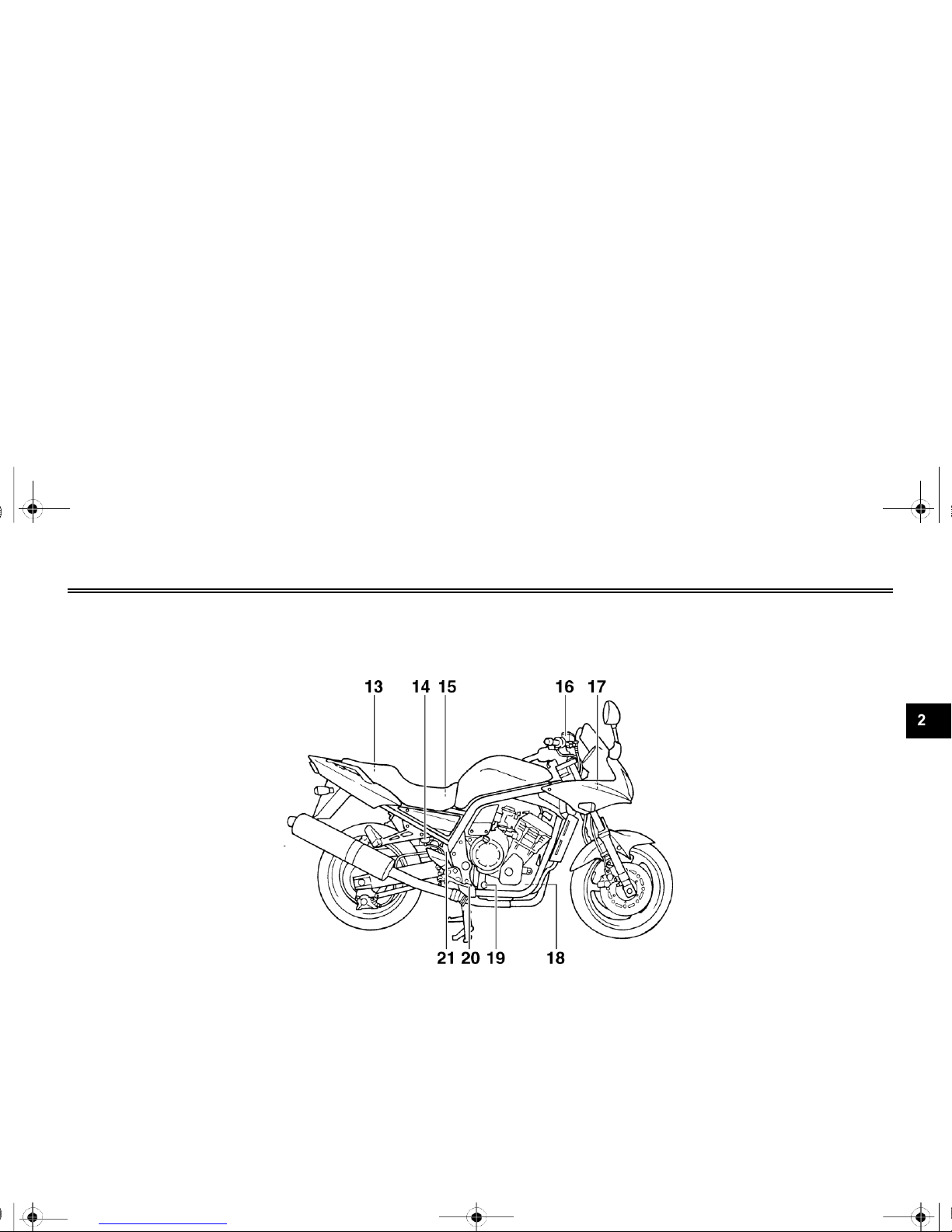
Right view
13.
Owner’s tool kit (page 6-1)
14.
Rear brake fluid reservoir (page 6-30)
15.
Battery (page 6-37)
16.
Front brake fluid reservoir (page 6-29)
17.
Radiator cap (page 6-17)
18.
Engine oil filter cartridge (page 6-13)
19.
Engine oil level check window (page 6-12)
20.
Brake pedal (page 3-8)
21.
Coolant reservoir (page 6-15)
2-2

U5LV12.book Page 3 Thursday, June 27, 2002 5:49 PM
DESCRIPTION
Controls and instruments
1.
Clutch lever (page 3-7)
2.
Left handlebar switches (page 3-6)
3.
Starter (choke) lever (page 3-10)
4.
Speedometer unit (page 3-3)
5.
Main switch/steering lock (page 3-1)
6.
Tachometer unit (page 3-4)
7.
Fuel gauge (page 3-5)
8.
Right handlebar switches (page 3-6)
9.
Brake lever (page 3-7)
10.
Throttle grip (page 6-22)
2-3
U5LV12.book Page 1 Thursday, June 27, 2002 5:49 PM
INSTRUMENT AND CONTROL FUNCTIONS
3
Main switch/steering lock..................................................................3-1
Indicator and warning lights ..............................................................3-2
Speedometer unit .............................................................................3-3
Tachometer unit................................................................................3-4
Self-diagnosis devices ......................................................................3-5
Fuel gauge .......................................................................................3-5
Handlebar switches ..........................................................................3-6
Clutch lever .............................................................................................. 3-7
Shift pedal ........................................................................................3-7
Brake lever ............................................................................................... 3-7
Brake pedal ......................................................................................3-8
Fuel tank cap ...................................................................................3-8
Fuel .................................................................................................3-9
Starter (choke) lever..............................................................................3-10
Seat ................................................................ ............................... 3-11
Helmet holder................................................................................. 3-11
Storage compartment ..................................................................... 3-12
Adjusting the front fork ................................................................... 3-12
Adjusting the shock absorber assembly .......................................... 3-14
EXUP system ................................................................................. 3-17
Sidestand ....................................................................................... 3-17
Ignition circuit cut-off system .......................................................... 3-18
WARNING
U5LV12.book Page 1 Thursday, June 27, 2002 5:49 PM
INSTRUMENT AND CONTROL FUNCTIONS
EAU00027
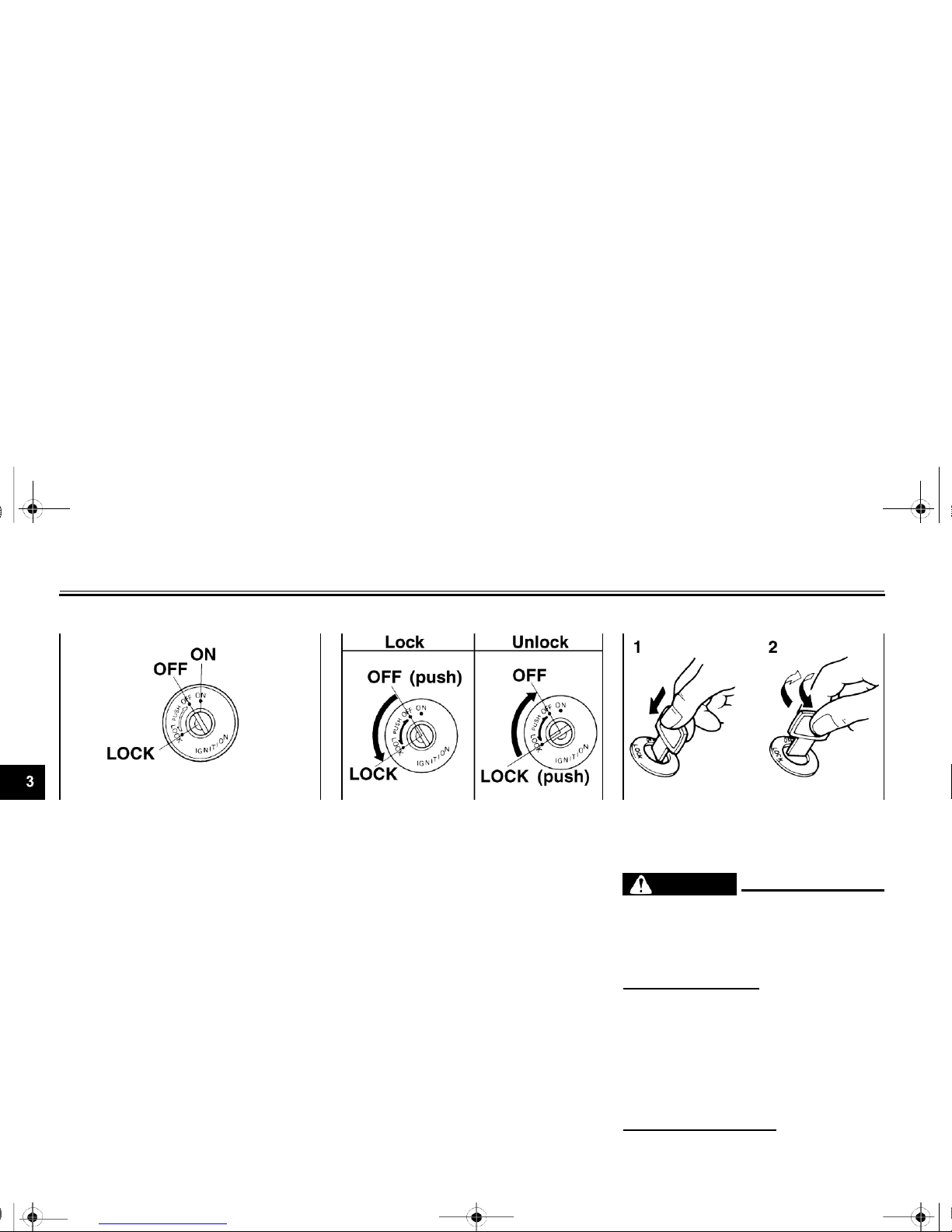
Main switch/steering lock
EAU00029
LOCK
EAU00040
1.
Push.
2.
Turn.
EW000016
The main switch/steering lock controls
the ignition and lighting systems, and is
The steering is locked, and all electrical
systems are off. The key can be
_
used to lock the steering. The various
positions are described below.
EAU00032
ON
All electrical systems are supplied with
power, and the headlight, meter lighting, taillight and position lights come
on, and the engine can be started. The
key cannot be removed.
EAU00038
OFF
All electrical systems are off. The key
can be removed.
removed.
To lock the steering
1.
Turn the handlebars all the way to the left.
2.
Push the key in from the “OFF” po- sition,
and then turn it to “LOCK” while still pushing
it.
3.
Remove the key.
To unlock the steering
Push the key in, and then turn it to “OFF” while
still pushing it.
3-1

Never turn the key to “OFF” or
“LOCK” while the motorcycle is
moving, otherwise the electrical
systems will be switched off,
which may result in loss of
control or an accident. Make
sure that the motor- cycle is
stopped before turning the key
to “OFF” or “LOCK”.
_
U5LV12.book Page 2 Thursday, June 27, 2002 5:49 PM
INSTRUMENT AND CONTROL FUNCTIONS
EAU00063
High beam indicator light “ ”
This indicator light comes on when the
high beam of the headlight is switched
on.
EAU04881
Coolant temperature warning light
“
”
This warning light comes on when the
engine overheats. When this occurs,
stop the engine immediately and allow
Oil level warning light “ ”
EAU04877
the engine to cool.
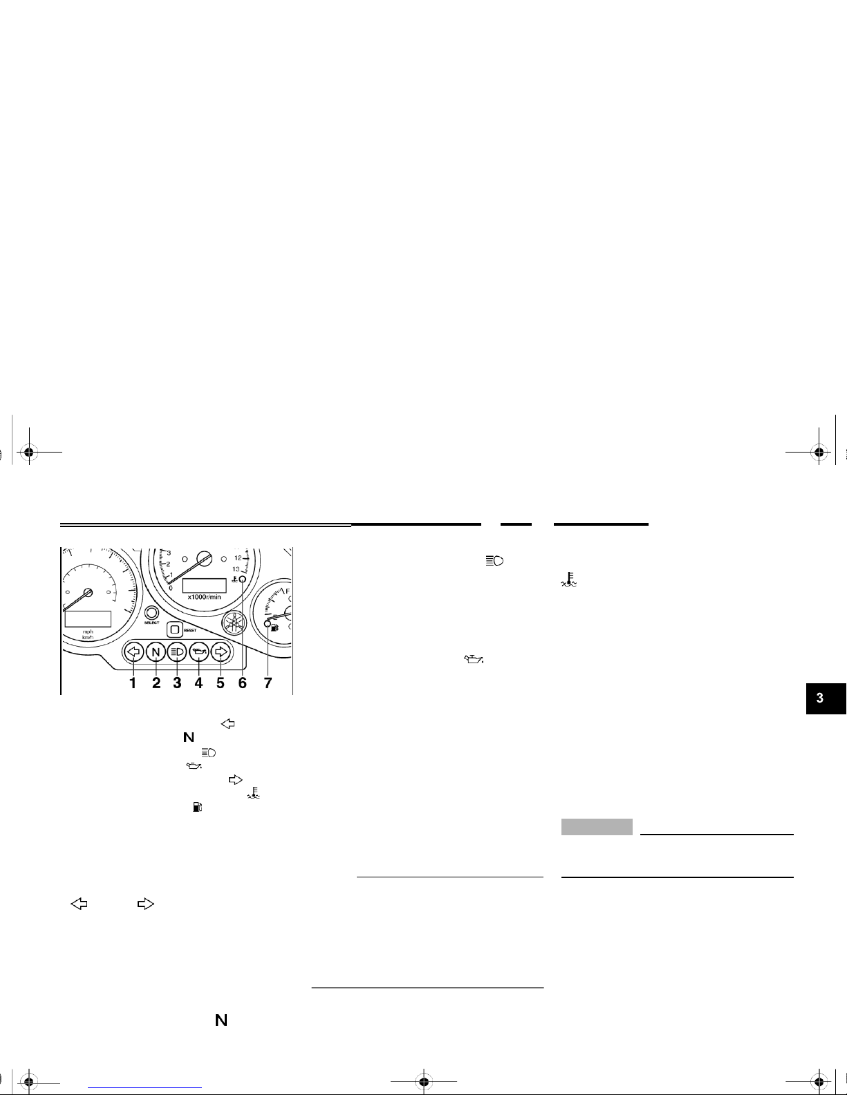
1.
Left turn signal indicator light “ ”
2.
Neutral indicator light “ ”
3.
High beam indicator light “ ”
4.
Oil level warning light “ ”
5.
Right turn signal indicator light “ ”
6.
Coolant temperature warning light “ ”
7.
Fuel level warning light “ ”
EAU03034
Indicator and warning lights
EAU04121
Turn signal indicator lights
“
” and “ ”
The corresponding indicator light flashes when the turn signal switch is
pushed to the left or right.
This warning light comes on when the
engine oil level is low.
The electrical circuit of the warning light
can be checked by turning the key to
“ON”.
If the warning light does not come on
for a few seconds, then go off, have a
Yamaha dealer check the electrical circuit.
NOTE:
Even if the oil level is sufficient, the
warning light may flicker when riding on
a slope or during sudden acceleration
or deceleration, but this is not a malfunction.
The electrical circuit of the warning light
can be checked by turning the key to
“ON”.
If the warning light does not come on
for a few seconds, then go off, have a
Yamaha dealer check the electrical circuit.
EC000002
CAUTION:
_
Do not operate the engine if it is overheated.
Neutral indicator light “ ”
EAU00061
This indicator light comes on when the
transmission is in the neutral position.

3-2
U5LV12.book Page 3 Thursday, June 27, 2002 5:49 PM
INSTRUMENT AND CONTROL FUNCTIONS
This information will enable you to plan
future fuel stops.
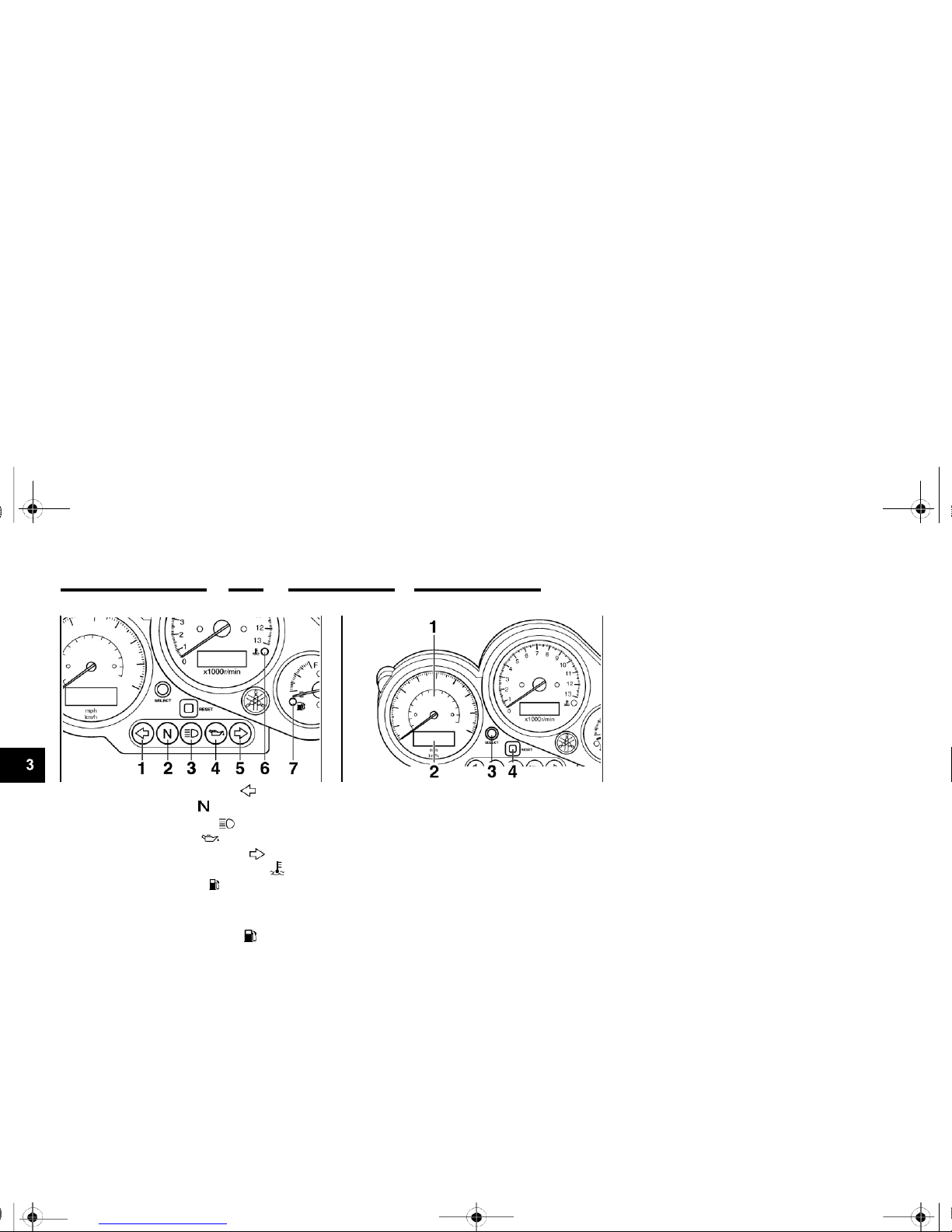
1.
Left turn signal indicator light “ ”
2.
Neutral indicator light “ ”
3.
High beam indicator light “ ”
4.
Oil level warning light “ ”
5.
Right turn signal indicator light “ ”
6.
Coolant temperature warning light “ ”
7.
Fuel level warning light “ ”
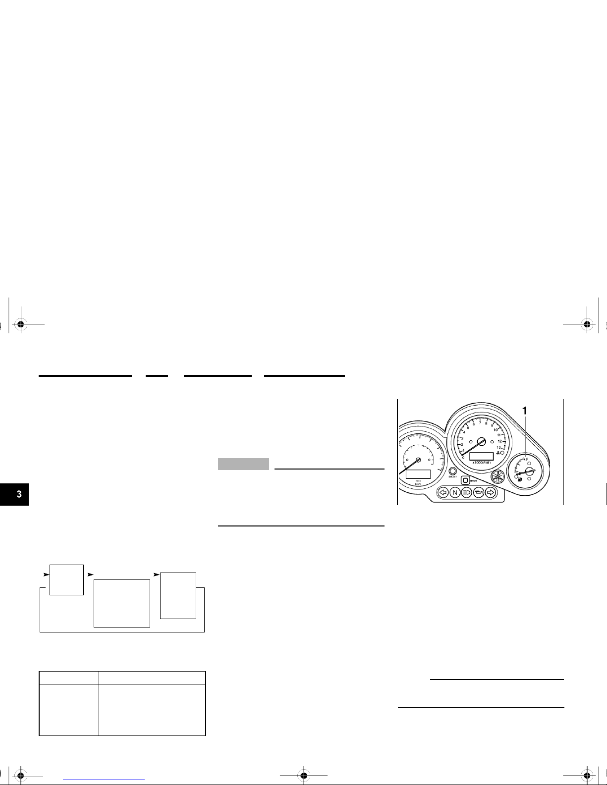
1.
Speedometer
2.
Odometer/tripmeter
3.
“SELECT” button
4.
“RESET” button
Speedometer unit
EAU04289
To set a mode
Push the “SELECT” button to change
between the odometer mode “ODO”,
and the tripmeter modes “TRIP 1” and
“TRIP 2” in the following order:
ODO TRIP 1 TRIP 2 ODO
To reset a meter
To reset either tripmeter 1 or 2 to 0.0,
select either by pushing the “SELECT”
button, and then push the “RESET”
Fuel level warning light “ ”
EAU04878
The speedometer unit is equipped with
the following:
button for at least one second.
This warning light comes on when the
fuel level drops below approximately 4
L (0.9 Imp gal, 1.1 US gal). When this
occurs, refuel as soon as possible.
The electrical circuit of the warning light
can be checked by turning the key to
“ON”.
If the warning light does not come on
for a few seconds, then go off, have a
Yamaha dealer check the electrical circuit.
●
an odometer
●
two tripmeters
When set to “ODO”, the motorcycle’s
total mileage is indicated.
When set to “TRIP 1” or “TRIP 2”, the
motorcycle’s mileage since the tripme-
ter was last reset is indicated. The tripmeters can be used together with the
fuel gauge to estimate the distance that
can be traveled on a full tank of fuel.
3-3
U5LV12.book Page 4 Thursday, June 27, 2002 5:49 PM
INSTRUMENT AND CONTROL FUNCTIONS
To set the clock:
1.
Push both the “SELECT” and
“RESET” buttons for at least two
seconds.
2.
When the hour digits start flashing,
push the “RESET” button to set
the hours.
3.
Push the “SELECT” button to
change the minutes.
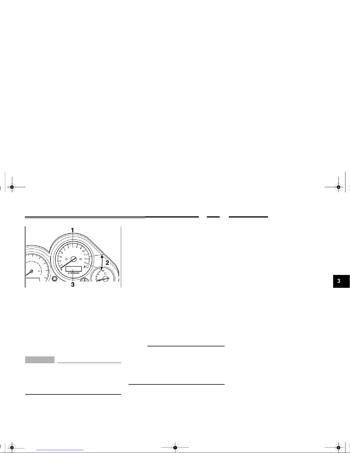
1.
Tachometer
2.
Tachometer red zone
3.
Clock
Tachometer unit
EAU03954
4.
When the minute digits start flash-
ing, push the “RESET” button to
set the minutes.
5.
Push the “SELECT” button to start
The electric tachometer allows the rider
to monitor the engine speed and keep it
within the ideal power range.
EC000003
CAUTION:
_
Do not operate the engine in the ta-
the clock.
NOTE:
After setting the clock, be sure to push
the “SELECT” button before turning the
key to “OFF”, otherwise the clock will
not be set.
chometer red zone. Red zone: 11,500 r/min and above
This tachometer unit is equipped with a
clock.
3-4
0 r/min for
Circuit-specific
number of r/min
U5LV12.book Page 5 Thursday, June 27, 2002 5:49 PM
INSTRUMENT AND CONTROL FUNCTIONS
Self-diagnosis devices
EAU04290
If the tachometer displays such an error code, note the circuit-specific num-
This model is equipped with a self-diagnosis device for the following electrical circuits:
●
throttle position sensor
●
speed sensor
●
EXUP system
●
overturn switch
If any of those circuits are defective,
the tachometer will repeatedly display
the following error code:
ber of r/min, and then have a Yamaha
dealer check the motorcycle.
EC000004
CAUTION:
_
When the tachometer displays an error code, the motorcycle should be checked as soon as possible in order to avoid engine damage.
1.
Fuel gauge
Fuel gauge
EAU00110
Current
engine
3 seconds
for 2.5 seconds
(See the table
speed for
3 seconds
below.)
Use the chart below to identify the
faulty electrical circuit.
Specific r/min
Faulty electrical circuit
3,000 r/min
Throttle position sensor
4,000 r/min
Speed sensor
7,000 r/min
EXUP system
9,000 r/min
Overturn switch
3-5
The fuel gauge indicates the amount of
fuel in the fuel tank. The needle moves
towards “E” (Empty) as the fuel level
decreases. When the needle reaches
“E”, approximately 4 L (0.9 Imp gal,
1.1
US gal) of fuel remain in the fuel
tank. If this occurs, refuel as soon as
possible.
NOTE:
Do not allow the fuel tank to empty itself completely.
U5LV12.book Page 6 Thursday, June 27, 2002 5:49 PM
INSTRUMENT AND CONTROL FUNCTIONS
Turn signal switch “ / ”
EAU03889
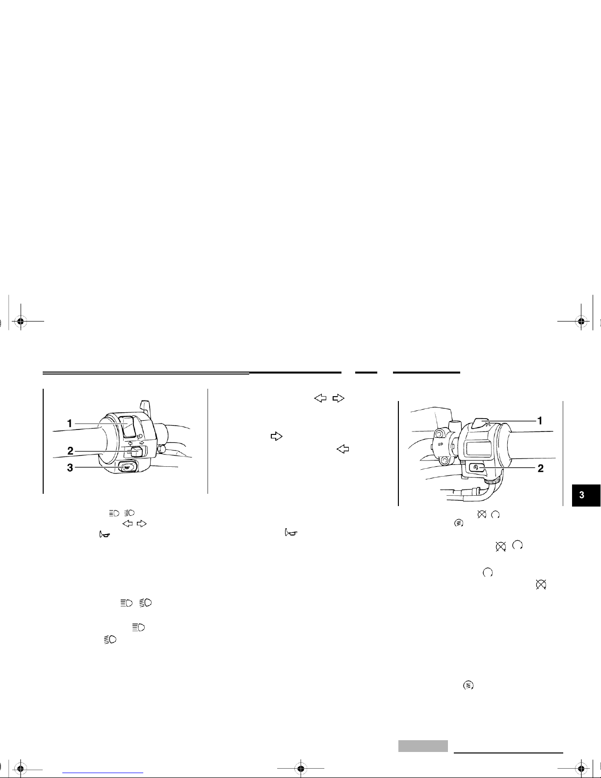
1.
Dimmer switch “
/
”
2.
Turn signal switch “ / ”
3.
Horn switch “ ”
EAU00118
To signal a right-hand turn, push this
switch to “ ”. To signal a left-hand
turn, push this switch to “ ”. When
released, the switch returns to the center position. To cancel the turn signal
lights, push the switch in after it has returned to the center position.
EAU00129
Horn switch “ ”
Press this switch to sound the horn.
1.
Engine stop switch “ / ”
2.
Start switch “ ”
Engine stop switch “
/
”
EAU03890
Handlebar switches
Dimmer switch “ / ”
EAU03888
Set this switch to “ ” before starting
the engine. Set this switch to “ ” to
stop the engine in case of an emergen-
Set this switch to “ ” for the high
beam and to “ ” for the low beam.
cy, such as when the motorcycle overturns or when the throttle cable is
stuck.
Start switch “ ”
EAU00143
Push this switch to crank the engine
with the starter.
CAUTION:
_
EC000005

See page 5-1 for starting instructions prior to starting the engine.
3-6

U5LV12.book Page 7 Thursday, June 27, 2002 5:49 PM
INSTRUMENT AND CONTROL FUNCTIONS
1.
Clutch lever 1. Shift pedal 1. Brake lever
2.
Brake lever position adjusting dial
Clutch lever
EAU00152
Shift pedal
EAU00157
3.
Arrow mark
a. Distance between brake lever and handlebar
The clutch lever is located at the left
handlebar grip. To disengage the
clutch, pull the lever toward the handle-
The shift pedal is located on the left
side of the engine and is used in combination with the clutch lever when
grip
Brake lever
EAU00161
bar grip. To engage the clutch, release
the lever. The lever should be pulled
rapidly and released slowly for smooth
clutch operation.
The clutch lever is equipped with a
clutch switch, which is part of the ignition
circuit cut-off system. (See page 3-18
for an explanation of the ignition circuit
cut-off system.)
shifting the gears of the 6-speed constant-mesh transmission equipped on
this motorcycle.
3-7
The brake lever is located at the right
handlebar grip. To apply the front brake,
pull the lever toward the handlebar grip.
The brake lever is equipped with a position adjusting dial. To adjust the distance between the brake lever and the
handlebar grip, turn the adjusting dial
while holding the lever pushed away
from the handlebar grip. Make sure that
the appropriate setting on the adjusting
dial is aligned with the arrow mark on
the brake lever.

U5LV12.book Page 8 Thursday, June 27, 2002 5:49 PM
INSTRUMENT AND CONTROL FUNCTIONS
2. Turn the key counterclockwise to
the original position, remove it,
and then close the lock cover.
NOTE:
The fuel tank cap cannot be closed unless the key is in the lock. In addition,
the key cannot be removed if the cap is
not properly closed and locked.
1.
Brake pedal 1. Fuel tank cap lock cover
2.
Unlock.
EAU00162
Brake pedal
EAU02935
_
EWA00025
The brake pedal is on the right side of
the motorcycle. To apply the rear
brake, press down on the brake pedal.
Fuel tank cap
To open the fuel tank cap
Open the fuel tank cap lock cover, insert the key into the lock, and then turn
it 1/4 turn clockwise. The lock will be released and the fuel tank cap can be
opened.
To close the fuel tank cap
1.
Push the fuel tank cap into position with the key inserted in the
lock.
Make sure that the fuel tank cap is properly closed before riding.
_
WARNING

3-8

U5LV12.book Page 9 Thursday, June 27, 2002 5:49 PM
INSTRUMENT AND CONTROL FUNCTIONS
CAUTION:
_
EAU00185 EAU04265
Immediately wipe off spilled fuel
with a clean, dry, soft cloth, since
fuel may deteriorate painted surfaces or plastic parts.
1.
Fuel tank filler tube
2.
Fuel level
EAU03753
CAUTION:
_
ECA00104
Fuel
Make sure that there is sufficient fuel in
the tank. Fill the fuel tank to the bottom
of the filler tube as shown.
EW000130
Use only unleaded gasoline. The
use of leaded gasoline will cause severe damage to internal engine
parts, such as the valves and piston
rings, as well as to the exhaust system.
_
●
Do not overfill the fuel tank, otherwise it may overflow when the
fuel warms up and expands.
●
Avoid spilling fuel on the hot
engine.
_
3-9
WARNING
Recommended fuel:
UNLEADED GASOLINE ONLY
Fuel tank capacity:
Total amount:
21 L (4.6 Imp gal, 5.5 US gal)
Reserve amount:
4 L (0.9 Imp gal, 1.1 US gal)

U5LV12.book Page 10 Thursday, June 27, 2002 5:49 PM
INSTRUMENT AND CONTROL FUNCTIONS
Your Yamaha engine has been designed to use regular unleaded gasoline with a pump octane number
[(R+M)/2] of 86 or higher, or a research
octane number of 91 or higher. If
knocking (or pinging) occurs, use a
gasoline of a different brand or premium unleaded fuel. Use of unleaded fuel
will extend spark plug life and reduce
maintenance costs.
Gasohol
There are two types of gasohol: gasohol containing ethanol and that containing methanol. Gasohol containing
ethanol can be used if the ethanol content does not exceed 10%. Gasohol
containing methanol is not recommended by Yamaha because it can
cause damage to the fuel system or vehicle performance problems.
EAU03839
Starter (choke) lever “ ”
Starting a cold engine requires a richer
air-fuel mixture, which is supplied by
the starter (choke).
Move the lever in direction a to turn on
the starter (choke).
Move the lever in direction b to turn off
the starter (choke).
3-10
1. Starter (choke) lever “ ”

U5LV12.book Page 11 Thursday, June 27, 2002 5:49 PM
INSTRUMENT AND CONTROL FUNCTIONS
1.
Seat lock
2.
Unlock.
Seat
EAU03956
1.
Projection
2.
Seat holder
To install the seat
1.
Insert the projection on the front of
1.
Helmet holder
2.
Unlock.
Helmet holder
EAU04291
To remove the seat
1.
Insert the key into the seat lock,
and then turn it clockwise.
2.
While holding the key in that position, lift the rear of the seat, and
then pull the seat off.
the seat into the seat holder as
shown.
2.
Push the rear of the seat down to
lock it in place.
3.
Remove the key.
NOTE:
Make sure that the seat is properly secured before riding.
To open the helmet holder, insert the
key into the seat lock, and then turn the
key as shown.
To lock the helmet holder, turn the key
to the original position, and then remove it.
EW000030
_
Never ride with a helmet attached to the helmet holder, since the helmet may hit objects, causing loss of control and possibly an accident.
_
3-11
WARNING

U5LV12.book Page 12 Thursday, June 27, 2002 5:49 PM
INSTRUMENT AND CONTROL FUNCTIONS
When storing the owner’s manual or
other documents in the storage com-
Adjusting the front fork
EAU04293
partment, be sure to wrap them in a
plastic bag so that they will not get wet.
When washing the motorcycle, be
careful not to let any water enter the
storage compartment.
This front fork is equipped with spring
preload adjusting bolts, rebound damping force adjusting screws and compression damping force adjusting
screws.
EW000035
_
1.
Storage compartment
Storage compartment
EAU04101
Always adjust both fork legs equally, otherwise poor handling and loss
of stability may result.
The storage compartment is located
_
under the seat. (See page 3-11 for seat
removal and installation procedures.)
EWA00005
_
●
Do not exceed the load limit of
3 kg (7 lb) for the storage compartment.
●
Do not exceed the maximum
load of FZS1000, FZS1000S:
189 kg (417 lb) / FZS1000C,
FZS1000SC: 188 kg (415 lb) for
the vehicle.
_
WARNING
WARNING

3-12

U5LV12.book Page 13 Thursday, June 27, 2002 5:49 PM
INSTRUMENT AND CONTROL FUNCTIONS
1.
Spring preload adjusting bolt 1. Current setting 1. Rebound damping force adjusting screw
Spring preload
To increase the spring preload and
thereby harden the suspension, turn
the adjusting bolt on each fork leg in direction
a.
To decrease the spring preload and thereby soften the
suspension, turn the adjusting bolt on
each fork leg in direction b.
2.
Front fork cap bolt
NOTE:
Align the appropriate groove on the adjusting mechanism with the top of the
front fork cap bolt.
Setting
Minimum (soft)
5*
Standard 2
Maximum (hard)
1
* fully turned out position
Rebound damping force
To increase the rebound damping
force and thereby harden the rebound
damping, turn the adjusting screw on
each fork leg in direction
a.
To decrease the rebound damping force and
thereby soften the rebound damping,
turn the adjusting screw on each fork
leg in direction b.
Minimum (soft)
17 clicks in direction b*
Standard
7 clicks in direction b*
Maximum (hard)
1 click in direction b*
*
With the adjusting screw fully turned in direction a
3-13

U5LV12.book Page 14 Thursday, June 27, 2002 5:49 PM
INSTRUMENT AND CONTROL FUNCTIONS
1.
Compression damping force adjusting screw
Compression damping force
To increase the compression damping
force and thereby harden the compression damping, turn the adjusting screw
on each fork leg in direction
a.
To decrease the compression damping force
and thereby soften the compression
damping, turn the adjusting screw on
each fork leg in direction b.
Minimum (soft)
21 clicks in direction b*
Standard
6 clicks in direction b*
Maximum (hard)
1 click in direction b*
*
With the adjusting screw fully turned in direction a
EC000015
CAUTION:
_
Never attempt to turn an adjusting mechanism beyond the maximum or minimum settings.
NOTE:
Although the total number of clicks of a
damping force adjusting mechanism
may not exactly match the above specifications due to small differences in
production, the actual number of clicks
always represents the entire adjusting
range. To obtain a precise adjustment,
it would be advisable to check the number of clicks of each damping force adjusting mechanism and to modify the
specifications as necessary.
EAU04295*
Adjusting the shock absorber
assembly
This shock absorber assembly is
equipped with a spring preload adjusting ring, a rebound damping force adjusting knob and a compression
damping force adjusting screw.
EC000015
CAUTION:
_
Never attempt to turn an adjusting
mechanism beyond the maximum
or minimum settings.
3-14

U5LV12.book Page 15 Thursday, June 27, 2002 5:49 PM
INSTRUMENT AND CONTROL FUNCTIONS
NOTE:
●
Align the appropriate notch in the
adjusting ring with the position indicator on the shock absorber.
●
Use the special wrench included in
the owner’s tool kit to make the ad-
justment.
1.
Spring preload adjusting ring
2.
Special wrench
3.
Position indicator
Spring preload
To increase the spring preload and
thereby harden the suspension, turn
the adjusting ring in direction
a.
To decrease the spring preload and thereby
soften the suspension, turn the adjusting ring in direction b.
1.
Rebound damping force adjusting knob
Rebound damping force
To increase the rebound damping
force and thereby harden the rebound
damping, turn the adjusting knob in direction
a.
To decrease the rebound
damping force and thereby soften the
rebound damping, turn the adjusting
knob in direction b.
Minimum (soft)
20 clicks in direction b*
Standard
10 clicks in direction b*
Maximum (hard)
3 clicks in direction b*
* With the adjusting knob fully turned in direction a
3-15
Setting
Minimum (soft)
1 Standard 6
Maximum (hard)
11

U5LV12.book Page 16 Thursday, June 27, 2002 5:49 PM
INSTRUMENT AND CONTROL FUNCTIONS
NOTE:
Although the total number of clicks of a
_
EAU00315
1.
Compression damping force adjusting screw
Compression damping force
To increase the compression damping
force and thereby harden the compression damping, turn the adjusting screw
in direction
a.
To decrease the compression damping force and thereby
soften the compression damping, turn
the adjusting screw in direction b.
Minimum (soft)
1 click in direction a*
Standard
7 clicks in direction a*
Maximum (hard)
12 clicks in direction a*
* With the adjusting screw fully turned in direction b
damping force adjusting mechanism
may not exactly match the above specifications due to small differences in
production, the actual number of clicks
always represents the entire adjusting
range. To obtain a precise adjustment,
it would be advisable to check the number of clicks of each damping force adjusting mechanism and to modify the
specifications as necessary.
This shock absorber contains highly pressurized nitrogen gas. For
proper handling, read and understand the following information before handling the shock absorber.
The manufacturer cannot be held responsible for property damage or
personal injury that may result from
improper handling.
●
Do not tamper with or attempt to
open the gas cylinder.
●
Do not subject the shock absorber to an open flame or other
high heat sources, otherwise it
may explode due to excessive
gas pressure.
●
Do not deform or damage the
gas cylinder in any way, as this
will result in poor damping performance.
●
Always have a Yamaha dealer
service the shock absorber.
_
3-16
WARNING

U5LV12.book Page 17 Thursday, June 27, 2002 5:49 PM
INSTRUMENT AND CONTROL FUNCTIONS
EXUP system
EAU01571
Sidestand
EAU00330 EW000044
This motorcycle is equipped with
Yamaha’s EXUP (EXhaust Ultimate
Power valve) system. This system
boosts engine power by means of a
valve that regulates the diameter of the
exhaust pipe. The EXUP system valve
is constantly adjusted in accordance
with the engine speed by a computercontrolled servomotor.
EC000027
_
●
The EXUP system has been set
and extensively tested at the
Yamaha factory. Changing
these settings without sufficient
technical knowledge may result
in poor performance of or damage to the engine.
●
If the EXUP system does not operate, have a Yamaha dealer
check it.
The sidestand is located on the left side
of the frame. Raise the sidestand or
lower it with your foot while holding the
motorcycle upright.
NOTE:
The built-in sidestand switch is part of
the ignition circuit cut-off system, which
cuts the ignition in certain situations.
(See further down for an explanation of
the ignition circuit cut-off system.)
_
The motorcycle must not be ridden
with the sidestand down, or if the
sidestand cannot be properly
moved up (or does not stay up), otherwise the sidestand could contact
the ground and distract the operator, resulting in a possible loss of
control. Yamaha’s ignition circuit
cut-off system has been designed to
assist the operator in fulfilling the
responsibility of raising the sidestand before starting off. Therefore,
check this system regularly as described below and have a Yamaha
dealer repair it if it does not function
properly.
_
WARNING
CAUTION:

3-17

U5LV12.book Page 18 Thursday, June 27, 2002 5:49 PM
INSTRUMENT AND CONTROL FUNCTIONS
EAU03741
Ignition circuit cut-off system
The ignition circuit cut-off system (comprising the sidestand switch, clutch
switch and neutral switch) has the following functions.
●
It prevents starting when the transmission is in gear and the sidestand is up, but the clutch lever is
not pulled.
●
It prevents starting when the transmission is in gear and the clutch
lever is pulled, but the sidestand is
still down.
●
It cuts the running engine when
the transmission is in gear and the
sidestand is moved down.
Periodically check the operation of the
ignition circuit cut-off system according
to the following procedure.
EW000046
_
●
The vehicle must be placed on
the centerstand during this inspection.
●
If a malfunction is noted, have a
Yamaha dealer check the system before riding.
_
3-18
WARNING

U5LV12.book Page 19 Thursday, June 27, 2002 5:49 PM
INSTRUMENT AND CONTROL FUNCTIONS
NOTE:
This check is most reliable if performed with
a warmed-up engine.
3-19
The system is OK. The motorcycle can be ridden.
The clutch switch may be defective.
The motorcycle should not be ridden until
checked by a Yamaha dealer.
The sidestand switch may be defective.
The motorcycle should not be ridden until
checked by a Yamaha dealer.
The neutral switch may be defective.
The motorcycle should not be ridden until
checked by a Yamaha dealer.
With the engine turned off:
1.
Move the sidestand down.
2.
Make sure that the engine stop switch is set to “ ”.
3.
Turn the key to “ON”.
4.
Shift the transmission into the neutral position.
5.
Push the start switch.
Does the engine start?
YES NO
With the engine still running:
6.
Move the sidestand up.
7.
Keep the clutch lever pulled.
8.
Shift the transmission into gear.
9.
Move the sidestand down.
Does the engine stall?
YES NO
After the engine has stalled:
10.
Move the sidestand up.
11.
Keep the clutch lever pulled.
12.
Push the start switch.
Does the engine start?
YES NO

U5LV12.book Page 1 Thursday, June 27, 2002 5:49 PM
PRE-OPERATION CHECKS
4
Pre-operation check list ....................................................................4-1

U5LV12.book Page 1 Thursday, June 27, 2002 5:49 PM
PRE-OPERATION CHECKS
EAU01114
The condition of a vehicle is the owner’s responsibility. Vital components can start to deteriorate quickly and unexpectedly,
even if the vehicle remains unused (for example, as a result of exposure to the elements). Any damage, fluid leakage or loss
of tire air pressure could have serious consequences. Therefore, it is very important, in addition to a thorough visual inspection, to check the following points before each ride.
Pre-operation check list
EAU03439
ITEM
CHECKS
PAGE
Fuel
•
Check fuel level in fuel tank.
•
Refuel if necessary.
•
Check fuel line for leakage.
3-9–3-10
Engine oil
•
Check oil level in engine.
•
If necessary, add recommended oil to specified level.
•
Check vehicle for oil leakage.
6-12
Coolant
•
Check coolant level in reservoir.
•
If necessary, add recommended coolant to specified level.
•
Check cooling system for leakage.
6-15–6-16
Front brake
•
Check operation.
•
If soft or spongy, have Yamaha dealer bleed hydraulic system.
•
Check fluid level in reservoir.
•
If necessary, add recommended brake fluid to specified level.
•
Check hydraulic system for leakage.
6-29–6-30
Rear brake
•
Check operation.
•
If soft or spongy, have Yamaha dealer bleed hydraulic system.
•
Check fluid level in reservoir.
•
If necessary, add recommended brake fluid to specified level.
•
Check hydraulic system for leakage.
6-27–6-30
Clutch
•
Check operation.
•
Lubricate cable if necessary.
•
Check lever free play.
•
Adjust if necessary.
6-27,
6-34

4-1

U5LV12.book Page 2 Thursday, June 27, 2002 5:49 PM
PRE-OPERATION CHECKS
ITEM
CHECKS
PAGE
Throttle grip
•
Make sure that operation is smooth.
•
Check cable free play.
•
If necessary, have Yamaha dealer adjust cable free play and lubricate cable and
grip housing.
6-22,
6-33
Control cables
•
Make sure that operation is smooth.
•
Lubricate if necessary.
6-33
Drive chain
•
Check chain slack.
•
Adjust if necessary.
•
Check chain condition.
•
Lubricate if necessary.
6-31–6-32
Wheels and tires
•
Check for damage.
•
Check tire condition and tread depth.
•
Check air pressure.
•
Correct if necessary.
6-23–6-26
Brake and shift pedals
•
Make sure that operation is smooth.
•
Lubricate pedal pivoting points if necessary.
6-33
Brake and clutch levers
•
Make sure that operation is smooth.
•
Lubricate lever pivoting points if necessary.
6-34
Centerstand, sidestand
•
Make sure that operation is smooth.
•
Lubricate pivots if necessary.
6-34
Chassis fasteners
•
Make sure that all nuts, bolts and screws are properly tightened.
•
Tighten if necessary.
—
Instruments, lights, signals
and switches
•
Check operation.
•
Correct if necessary.
—
Sidestand switch
•
Check operation of ignition circuit cut-off system.
•
If system is defective, have Yamaha dealer check vehicle.
3-17
4-2

U5LV12.book Page 3 Thursday, June 27, 2002 5:49 PM
PRE-OPERATION CHECKS
NOTE:
Pre-operation checks should be made each time the motorcycle is used. Such an inspection can be accomplished in a very
short time; and the added safety it assures is more than worth the time involved.
EWA00033
_
If any item in the Pre-operation check list is not working properly, have it inspected and repaired before operating the motorcycle.
_
4-3
WARNING

U5LV12.book Page 1 Thursday, June 27, 2002 5:49 PM
OPERATION AND IMPORTANT RIDING POINTS
5
Starting and warming up a cold engine .............................................5-1
Starting a warm engine ....................................................................5-3
Shifting.............................................................................................5-4
Engine break-in ................................................................................5-5
Parking ............................................................................................5-6

U5LV12.book Page 1 Thursday, June 27, 2002 5:49 PM
OPERATION AND IMPORTANT RIDING POINTS
EAU00372
EAU00373
_
●
Become thoroughly familiar
with all operating controls and
their functions before riding.
Consult a Yamaha dealer regarding any control or function
that you do not thoroughly
understand.
●
Never start the engine or operate it in a closed area for any
length of time. Exhaust fumes
are poisonous, and inhaling
them can cause loss of consciousness and death within a
short time. Always make sure
that there is adequate ventilation.
●
Before starting out, make sure
that the sidestand is up. If the
sidestand is not raised completely, it could contact the
ground and distract the operator, resulting in a possible loss
of control.
EAU00376
CAUTION:
_
●
Make sure not to store personal
items near the air cleaner intake, otherwise air intake will be
blocked and performance will
suffer.
●
Make sure not to put anything
near the battery and its terminals, otherwise electrical failure
and acid corrosion may result.
EAU04827
Starting and warming up a
cold engine
In order for the ignition circuit cut-off
system to enable starting, one of the
following conditions must be met:
●
The transmission is in the neutral
position.
●
The transmission is in gear with
the clutch lever pulled and the
sidestand up.
EW000054
_
●
Before starting the engine,
check the function of the ignition circuit cut-off system according to the procedure
described on page 3-19.
●
Never ride with the sidestand
down.
_
_
WARNING
WARNING

5-1

U5LV12.book Page 2 Thursday, June 27, 2002 5:49 PM
OPERATION AND IMPORTANT RIDING POINTS
1.
Turn the key to “ON” and make
sure that the engine stop switch is
set to “ ”.
ECA00108
CAUTION:
_
The oil level warning light, coolant temperature warning light and fuel level warning light should come on for a few seconds, then go off. If a warning light does not go off, have a
4.
Start the engine by pushing the
start switch.
NOTE:
If the engine fails to start, release the
start switch, wait a few seconds, and
then try again. Each starting attempt
should be as short as possible to preserve the battery. Do not crank the engine more than 10 seconds on any one
attempt.
with sufficient engine oil, have a
Yamaha dealer check the electrical circuit.
●
If the coolant temperature warn-
ing light flickers or remains on
after starting, immediately stop
the engine, and then check the
coolant level and the vehicle for
coolant leakage. If necessary,
add coolant, and then check the
Yamaha dealer check the electrical
warning light again. If, when the
circuit.
2.
Shift the transmission into the neutral position.
NOTE:
When the transmission is in the neutral
position, the neutral indicator light
should be on, otherwise have a
Yamaha dealer check the electrical circuit.
3.
Turn the starter (choke) on and
completely close the throttle. (See
page 3-10 for starter (choke) operation.)
ECA00116
CAUTION:
_
●
If the oil level warning light flickers or remains on after starting,
immediately stop the engine,
and then check the engine oil
level and the vehicle for oil leakage. If necessary, add engine
oil, and then check the warning
light again. If, when the key is
turned to “ON”, the warning
light does not come on for a few
seconds, then go off, or if it
does not go off after starting
key is turned to “ON”, the warn-
ing light does not come on for a
few seconds, then go off, or if it
does not go off after starting
with sufficient coolant, have a
Yamaha dealer check the elec-
trical circuit.
●
If the fuel level warning light re -
mains on after starting, stop the
engine, and then check the fuel
level. If necessary, refuel as
soon as possible, and then
check the warning light again.
If, when the key is turned to
“ON”, the warning light does
5-2

U5LV12.book Page 3 Thursday, June 27, 2002 5:49 PM
OPERATION AND IMPORTANT RIDING POINTS
not come on for a few seconds, then go off, or if it does not go
NOTE:
The engine is warm when it responds
Starting a warm engine
EAU01258
off after starting with sufficient fuel, have a Yamaha dealer check the electrical circuit.
_
5.
After starting the engine, move the
starter (choke) back halfway.
ECA00055
normally to the throttle with the starter
(choke) turned off. To avoid the possibility of excessive exhaust emissions,
never leave the starter (choke) on longer than necessary. The time necessary
for starter (choke) use depends upon
Follow the same procedure as for starting a cold engine with the exception
that the starter (choke) is not required
when the engine is warm.
CAUTION:
_
For maximum engine life, always warm the engine up before starting off. Never accelerate hard when the engine is cold!
_
the ambient temperature. Temperatures above 10 °C (50 °F) require about
10 seconds of starter (choke) use and
temperatures below 10 °C (50 °F) require about 35 seconds with the starter
(choke) turned on, then about 2.5 min-
6.
When the engine is warm, turn the
starter (choke) off.
utes with the starter (choke) in the halfway position.

5-3

U5LV12.book Page 4 Thursday, June 27, 2002 5:49 PM
OPERATION AND IMPORTANT RIDING POINTS
EC000048
CAUTION:
To start out and accelerate
EAU02988
1. Shift pedal
N. Neutral position
Shifting
EAU00423
_
●
Even with the transmission in
the neutral position, do not
coast for long periods of time
with the engine off, and do not
tow the motorcycle for long distances. The transmission is
properly lubricated only when
the engine is running. Inadequate lubrication may damage
the transmission.
1.
Pull the clutch lever to disengage
the clutch.
2.
Shift the transmission into first
gear. The neutral indicator light
should go out.
3.
Open the throttle gradually, and at
the same time, release the clutch
lever slowly.
4.
At the recommended shift points
shown in the table on page 5-5,
Shifting gears lets you control the
amount of engine power available for
starting off, accelerating, climbing hills,
etc.
The gear positions are shown in the
illustration.
NOTE:
To shift the transmission into the neutral position, press the shift pedal down
repeatedly until it reaches the end of its
travel, and then slightly raise it.
●
Always use the clutch while
changing gears to avoid damaging the engine, transmission,
and drive train, which are not
designed to withstand the
shock of forced shifting.
close the throttle, and at the same
time, quickly pull the clutch lever
in.
5.
Shift the transmission into second
gear. (Make sure not to shift the
transmission into the neutral posi-
tion.)
6.
Open the throttle part way and
gradually release the clutch lever.
7.
Follow the same procedure when
shifting to the next higher gear.
NOTE:
Always shift gears at the recommended shift points.

5-4

U5LV12.book Page 5 Thursday, June 27, 2002 5:49 PM
OPERATION AND IMPORTANT RIDING POINTS
To decelerate
EAU00427
Recommended shift points
EAU02989
Engine break-in
EAU01128
1.
Apply both the front and the rear
brakes to slow the motorcycle.
2.
Shift the transmission into first
gear when the motorcycle reaches
25 km/h (15.5 mi/h). If the engine
is about to stall or runs very roughly, pull the clutch lever in and use
the brakes to stop the motorcycle.
3.
Shift the transmission into the neutral position when the motorcycle
is almost completely stopped. The
neutral indicator light should come
on.
The recommended shift points during
acceleration and deceleration are
shown in the table below.
Acceleration
shift point
km/h (mi/h)
Deceleration
shift point
km/h (mi/h)
1st 2nd
16 (9.9) –
2nd 3rd
24 (14.9)
25 (15.5)
3rd 4th
32 (19.9)
25 (15.5)
4th 5th
40 (24.9)
25 (15.5)
5th 6th
48 (29.8)
25 (15.5)
There is never a more important period
in the life of your engine than the period
between 0 and 1,600 km (1,000 mi).
For this reason, you should read the
following material carefully.
Since the engine is brand new, do not
put an excessive load on it for the first
1,600 km (1,000 mi). The various parts
in the engine wear and polish themselves to the correct operating clearances. During this period, prolonged
full-throttle operation or any condition
that might result in engine overheating
must be avoided.
5-5

U5LV12.book Page 6 Thursday, June 27, 2002 5:49 PM
OPERATION AND IMPORTANT RIDING POINTS
0–1,000 km (0–600 mi)
EAU03749*
Parking
EAU00460
Avoid prolonged operation above
5,000 r/min.
1,000–1,600 km (600–1,000 mi)
Avoid prolonged operation above
6,000 r/min.
EC000052*
CAUTION:
_
After 1,000 km (600 mi) of operation, the engine oil must be changed and the oil filter cartridge replaced.
1,600 km (1,000 mi) and beyond
The vehicle can now be operated
normally.
When parking, stop the engine, and
then remove the key from the main
switch.
EW000058
_
●
Since the engine and exhaust
system can become very hot,
park in a place where pedestrians or children are not likely to
touch them.
●
Do not park on a slope or on
soft ground, otherwise the
motorcycle may overturn.
_
CAUTION:
_
EC000053
●
Keep the engine speed out of
the tachometer red zone.
●
If any engine trouble should occur during the engine break-in
period, immediately have a
Yamaha dealer check the vehicle.
WARNING

5-6

U5LV12.book Page 1 Thursday, June 27, 2002 5:49 PM
PERIODIC MAINTENANCE AND MINOR REPAIR
Periodic maintenance ..........................................6-1
Owner’s tool kit ....................................................6-1
Periodic maintenance chart for the emission
control system .................................................. 6-3
General maintenance and lubrication chart ..........6-5
Removing and installing panels .......................... 6-8
Checking the spark plugs .................................. 6-10
Canister (for California only) .............................. 6-11
Engine oil and oil filter cartridge ......................... 6-12
Coolant ............................................................. 6-15
Cleaning the air filter element ............................ 6-19
Adjusting the carburetors ................................... 6-21
Adjusting the throttle cable free play.................... 6-22
Adjusting the valve clearance ............................ 6-22
Tires.................................................................. 6-23
Cast wheels ...................................................... 6-26
Accessories and replacement parts ................... 6-26
Adjusting the clutch lever free play ...................... 6-27
Adjusting the brake pedal position ..................... 6-27
Adjusting the rear brake light switch ................... 6-28
Checking the front and rear brake pads ............. 6-29
Checking the brake fluid level .............................. 6-29
Changing the brake fluid .................................... 6-30
Drive chain slack ............................................... 6-31
Lubricating the drive chain ................................. 6-32
Checking and lubricating the cables................... 6-33
Checking and lubricating the throttle grip and
cable ............................................................... 6-33
Checking and lubricating the brake and
shift pedals...................................................... 6-33
Checking and lubricating the brake and
clutch levers ......................................................... 6-34
Checking and lubricating the centerstand and
idestand .......................................................... 6-34
Lubricating the rear suspension ......................... 6-35
Checking the front fork ...................................... 6-35
Checking the steering ....................................... 6-36
6
Checking the wheel bearings ............................. 6-36
Battery .............................................................. 6-37
Replacing the fuses ........................................... 6-38
Replacing a headlight bulb ................................ 6-39
Replacing a tail/brake light bulb ......................... 6-41
Replacing a turn signal light bulb ....................... 6-41
Front wheel ....................................................... 6-42
Rear wheel........................................................ 6-43
Troubleshooting ..................................................... 6-45
Troubleshooting charts ...................................... 6-46


U5LV12.book Page 1 Thursday, June 27, 2002 5:49 PM
PERIODIC MAINTENANCE AND MINOR REPAIR
EAU00462
EAU01790
Safety is an obligation of the owner.
Periodic inspection, adjustment and lubrication will keep your vehicle in the
safest and most efficient condition possible. The most important points of
motorcycle inspection, adjustment, and
lubrication are explained on the following pages.
Maintenance, replacement, or repair of the emission control devices and systems may be performed by any
EAU00467
PERIODIC MAINTENANCE
PROPER PERIODIC MAINTENANCE
OF YOUR MOTORCYCLE IS IMPORTANT IN ORDER TO ENJOY LONG,
PLEASURABLE SERVICE. ESPECIALLY IMPORTANT ARE THE
MAINTENANCE SERVICES RELATED TO EMISSIONS CONTROL.
THESE CONTROLS NOT ONLY
FUNCTION TO ENSURE CLEANER
AIR, BUT ARE ALSO VITAL TO
1.
Owner’s tool kit
Owner’s tool kit
EAU04479
repair establishment or individual
that is certified (if applicable).
EW000060
_
If you are not familiar with motorcycle maintenance work, have a
Yamaha dealer do it for you.
_
PROPER ENGINE OPERATION AND
MAXIMUM PERFORMANCE. IN THE
FOLLOWING PERIODIC MAINTENANCE CHARTS, THE SERVICES
RELATED TO EMISSIONS CONTROL ARE GROUPED SEPARATELY. THESE SERVICES REQUIRE
SPECIALIZED DATA, KNOWLEDGE,
AND EQUIPMENT. YAMAHA DEALERS ARE TRAINED AND EQUIPPED
TO PERFORM THESE PARTICULAR
SERVICES.
The owner’s tool kit is located inside
the storage compartment under the
seat. (See page 3-11 for seat removal
and installation procedures.)
The service information included in this
manual and the tools provided in the
owner’s tool kit are intended to assist
you in the performance of preventive
maintenance and minor repairs. However, additional tools such as a torque
wrench may be necessary to perform
certain maintenance work correctly.
WARNING

6-1

U5LV12.book Page 2 Thursday, June 27, 2002 5:49 PM
PERIODIC MAINTENANCE AND MINOR REPAIR
NOTE:
If you do not have the tools or experience required for a particular job, have
a Yamaha dealer perform it for you.
EW000062
_
Modifications not approved by
Yamaha may cause loss of performance, excessive emissions, and
render the vehicle unsafe for use.
Consult a Yamaha dealer before attempting any changes.
_
6-2
WARNING

U5LV12.book Page 3 Thursday, June 27, 2002 5:49 PM
PERIODIC MAINTENANCE AND MINOR REPAIR
Periodic maintenance chart for the emission control system
EAU00471
6-3
No.
ITEM
ROUTINE
INITIAL
ODOMETER READINGS
600 mi
(1,000 km)
or
1 month
4,000 mi
(7,000 km)
or
6 months
8,000 mi
(13,000 km)
or
12 months
12,000 mi
(19,000 km)
or
18 months
16,000 mi
(25,000 km)
or
24 months
20,000 mi
(31,000 km)
or
30 months
1
*
Valve clearance
•
Check and adjust valve clearance
when engine is cold.
Every 26,600 mi (42,000 km)
2
Spark plugs
•
Check condition.
•
Adjust gap and clean.
•
Replace every 8,000 mi (13,000 km) or
12 months.
Replace.
Replace.
3
*
Crankcase
ventilation system
•
Check ventilation hose for cracks or
damage.
•
Replace if necessary.
4
*
Fuel line
•
Check fuel hoses and vacuum hose
for cracks or damage.
•
Replace if necessary.
5
*
Fuel filter
•
Replace every 20,000 mi (31,000 km)
or 30 months.
Replace.
6
*
Exhaust system
•
Check for leakage.
•
Retighten if necessary.
•
Replace gasket(s) if necessary.
7
*
Carburetor
synchronization
•
Adjust synchronization of carburetors.
8
*
Idle speed
•
Check and adjust engine idle speed.
•
Adjust cable free play.

U5LV12.book Page 4 Thursday, June 27, 2002 5:49 PM
PERIODIC MAINTENANCE AND MINOR REPAIR
No.
ITEM
ROUTINE
INITIAL
ODOMETER READINGS
600 mi
(1,000 km)
or
1 month
4,000 mi
(7,000 km)
or
6 months
8,000 mi
(13,000 km)
or
12 months
12,000 mi
(19,000 km)
or
18 months
16,000 mi
(25,000 km)
or
24 months
20,000 mi
(31,000 km)
or
30 months
9
*
Evaporative
emission control
system (For
California only)
•
Check control system for damage.
•
Replace if necessary.
10
*
Air induction
system
•
Check the air cut valve and reed valve
for damage.
•
Replace the entire air induction
system if necessary.
* Since these items require special tools, data and technical skills, have a Yamaha dealer perform the service.
6-4

U5LV12.book Page 5 Thursday, June 27, 2002 5:49 PM
PERIODIC MAINTENANCE AND MINOR REPAIR
General maintenance and lubrication chart
EAU00472
6-5
No.
ITEM
ROUTINE
INITIAL
ODOMETER READINGS
600 mi
(1,000 km)
or
1 month
4,000 mi
(7,000 km)
or
6 months
8,000 mi
(13,000 km)
or
12 months
12,000 mi
(19,000 km)
or
18 months
16,000 mi
(25,000 km)
or
24 months
20,000 mi
(31,000 km)
or
30 months
1
Engine oil
•
Replace (warm engine before
draining). (See NOTE on page 6-7.)
2
Engine oil filter
cartridge
•
Replace at initial 600 mi (1,000 km) or
1 month, and thereafter every
8,000 mi (13,000 km) or 12 months.
3
*
Air filter element
•
Clean with compressed air.
•
Replace if necessary.
4
*
Cooling system
•
Check hose for cracks or damage.
•
Replace if necessary.
•
Replace coolant every 24 months. #3
Replace.
5
*
Brake system
•
Check operation, pad wear, and fluid
leakage. (See NOTE on page 6-7.)
•
Correct if necessary.
6
*
Clutch
•
Check operation.
•
Adjust or replace cable.
7
*
Control cable
•
Apply chain lube thoroughly. #1
8
*
Throttle grip
housing and
cable
•
Check operation and free play.
•
Adjust the throttle cable free play if
necessary.
•
Lubricate the throttle grip housing and
cable.

U5LV12.book Page 6 Thursday, June 27, 2002 5:49 PM
PERIODIC MAINTENANCE AND MINOR REPAIR
No.
ITEM
ROUTINE
INITIAL
ODOMETER READINGS
600 mi
(1,000 km)
or
1 month
4,000 mi
(7,000 km)
or
6 months
8,000 mi
(13,000 km)
or
12 months
12,000 mi
(19,000 km)
or
18 months
16,000 mi
(25,000 km)
or
24 months
20,000 mi
(31,000 km)
or
30 months
9
*
Swingarm pivot
bearing
•
Check bearing assembly for
looseness.
•
Moderately repack every 16,000 mi
(25,000 km) or 24 months. #2
Repack.
10
*
Rear suspension
link pivots
•
Check operation.
•
Moderately repack every 16,000 mi
(25,000 km) or 24 months. #2
Repack.
11
*
Shock absorber
assembly
•
Check operation and for oil leakage.
•
Replace if necessary.
12
*
Front fork
•
Check operation and for oil leakage.
•
Repair if necessary.
13
*
Steering bearings
•
Check bearing assembly for
looseness.
•
Moderately repack every 16,000 mi
(25,000 km) or 24 months. #2
Repack.
14
Brake and clutch
lever pivot shafts
•
Lubricate. #2
15
Brake and shift
pedal pivot shafts
•
Lubricate. #2
16
*
Drive chain
•
Check chain slack/alignment
condition.
•
Adjust and lubricate chain thoroughly.
#1
Every 600 mi (1,000 km) or after washing the motorcycle
or riding in the rain.
17
*
Wheel bearings
•
Check bearings for smooth operation.
18
*
Sidestand and
centerstand
pivots
•
Check operation.
•
Lubricate. #2
6-6

U5LV12.book Page 7 Thursday, June 27, 2002 5:49 PM
PERIODIC MAINTENANCE AND MINOR REPAIR
*
Since these items require special tools, data and technical skills, have a Yamaha dealer perform the service.
#1 : Yamaha chain lube
#2 : Lithium-soap-based grease (all-purpose grease)
#3 : Ethylene glycol anti-freeze coolant
EAU03907
NOTE:
From 24,000 mi (37,000 km) or 36 months, repeat the maintenance intervals starting from 4,000 mi (7,000 km) or 6 months.
EAU03234*
NOTE:
●
The air filter needs more frequent service if you are riding in unusually wet or dusty areas.
●
Hydraulic brake service
•
Regularly check and, if necessary, correct the brake fluid level.
•
Every two years replace the internal components of the brake master cylinders and calipers, and change the brake
fluid.
•
Replace the brake hoses every four years and if cracked or damaged.
●
Engine oil type
•
Yamalube 4 (20W-40) or engine oil SAE 20W-40 (API SE) for temperatures of 5 °C (40 °F) or above.
•
Yamalube 4 (10W-30) or engine oil SAE 10W-30 (API SE) for temperatures of 15 °C (60 °F) or below.
6-7
No.
ITEM
ROUTINE
INITIAL
ODOMETER READINGS
600 mi
(1,000 km)
or
1 month
4,000 mi
(7,000 km)
or
6 months
8,000 mi
(13,000 km)
or
12 months
12,000 mi
(19,000 km)
or
18 months
16,000 mi
(25,000 km)
or
24 months
20,000 mi
(31,000 km)
or
30 months
19
*
Sidestand switch
•
Check and clean or replace if
necessary.
20
*
Chassis fasteners
•
Check all chassis fitting and fasteners.
•
Correct if necessary.
21
*
Muffler and
exhaust pipe
•
Check the screw clamp for looseness.

U5LV12.book Page 8 Thursday, June 27, 2002 5:49 PM
PERIODIC MAINTENANCE AND MINOR REPAIR
1.
Panel A
2.
Panel B
1.
Panel C 1. Panel A
2.
Screw
Removing and installing panels
EAU01122
Panels A and C
To remove one of the panels
EAU04003
The panels shown above need to be
removed to perform some of the maintenance jobs described in this chapter.
Refer to this section each time a panel
needs to be removed and installed.
Remove the screw, and then pull the
panel off as shown.

6-8

U5LV12.book Page 9 Thursday, June 27, 2002 5:49 PM
PERIODIC MAINTENANCE AND MINOR REPAIR
1.
Panel C
2.
Screw
To install the panel
Place the panel in the original position,
and then install the screw
1.
Panel B
2.
Screw ( 3)
Panel B
To remove the panel
EAU01315
Remove the screws, and then take the
panel off.
To install the panel
Place the panel in the original position,
and then install the screws.
6-9

U5LV12.book Page 10 Thursday, June 27, 2002 5:49 PM
PERIODIC MAINTENANCE AND MINOR REPAIR
NOTE:
If any spark plug shows a distinctly different color, the engine could be defective. Do not attempt to diagnose such
problems yourself. Instead, have a
Yamaha dealer check the motorcycle.
3.
Check each spark plug for electrode erosion and excessive car-
1.
Spark plug cap 1. Spark plug wrench
bon or other deposits, and replace
it if necessary.
EAU03329
Checking the spark plugs
The spark plugs are important engine
components, which are easy to check.
Since heat and deposits will cause any
spark plug to slowly erode, the spark
plugs should be removed and checked
in accordance with the periodic maintenance and lubrication chart. In addition,
the condition of the spark plugs can reveal the condition of the engine.
To remove a spark plug
1.
Remove the spark plug cap.
2.
Remove the spark plug as shown,
with the spark plug wrench included in the owner’s tool kit.
To check the spark plugs
1.
Check that the porcelain insulator
around the center electrode on
each spark plug is a medium-tolight tan (the ideal color when the
motorcycle is ridden normally).
2.
Check that all spark plugs installed
in the engine have the same color.
6-10
Specified spark plug:
CR9E (NGK) or
U27ESR-N (DENSO)

U5LV12.book Page 11 Thursday, June 27, 2002 5:49 PM
PERIODIC MAINTENANCE AND MINOR REPAIR
3.
Install the spark plug with the
spark plug wrench, and then tighten it to the specified torque.
a. Spark plug gap
To install a spark plug
1.
Measure the spark plug gap with a
wire thickness gauge and, if necessary, adjust the gap to specification.
2.
Clean the surface of the spark
plug gasket and its mating surface, and then wipe off any grime
from the spark plug threads.
NOTE:
If a torque wrench is not available when
installing a spark plug, a good estimate
of the correct torque is 1/4–1/2 turn
past finger tight. However, the spark
plug should be tightened to the specified torque as soon as possible.
4.
Install the spark plug cap.
EAU01796
Canister (for California only)
This model is equipped with a canister
to prevent the discharging of fuel vapor
into the atmosphere.
●
Check each hose connection.
●
Check each hose and canister for
cracks or damage. Replace if
damaged.
●
Make sure the vent hose is not
blocked. Clean it if necessary.
6-11
Spark plug gap:
0.7–0.8 mm (0.028–0.031 in)
Tightening torque:
Spark plug:
12.5 Nm (1.25 m·kgf, 9.0 ft·lbf)

U5LV12.book Page 12 Thursday, June 27, 2002 5:49 PM
PERIODIC MAINTENANCE AND MINOR REPAIR
Engine oil and oil filter cartridge
EAU04625
To change the engine oil (with or
without oil filter cartridge replacement)
The engine oil level should be checked
before each ride. In addition, the oil
must be changed and the oil filter cartridge replaced at the intervals specified in the periodic maintenance and
lubrication chart.
To check the engine oil level
1.
Place the motorcycle on the centerstand.
NOTE:
Make sure that the motorcycle is positioned straight up when checking the oil
level. A slight tilt to the side can result in
a false reading.
2.
Start the engine, warm it up for
several minutes, and then turn it
off.
1.
Engine oil filler cap
2.
Engine oil level check window
3.
Maximum level mark
4.
Minimum level mark
3.
Wait a few minutes until the oil settles, and then check the oil level
through the check window located
at the bottom-right side of the
crankcase.
NOTE:
The engine oil should be between the
minimum and maximum level marks.
4.
If the engine oil is below the mini-
mum level mark, add sufficient oil
of the recommended type to raise
it to the correct level.
1.
Start the engine, warm it up for
several minutes, and then turn it
off.
2.
Place an oil pan under the engine
to collect the used oil.

6-12

U5LV12.book Page 13 Thursday, June 27, 2002 5:49 PM
PERIODIC MAINTENANCE AND MINOR REPAIR
1.
Engine oil drain bolt
3. Remove the engine oil filler cap
and drain bolt to drain the oil from
the crankcase.
NOTE:
●
Skip steps 4–6 if the oil filter cartridge is not being replaced.
●
When draining the engine oil, use
a funnel or similar device to keep
the oil away from the exhaust pipe.
1.
Oil filter wrench
2.
Oil filter cartridge
4. Remove the oil filter cartridge with
an oil filter wrench.
NOTE:
An oil filter wrench is available at a
Yamaha dealer.
1.
O-ring
5.
Apply a thin coat of engine oil to
the O-ring of the new oil filter cartridge.
NOTE:
Make sure that the O-ring is properly
seated.
6-13
Left side

U5LV12.book Page 14 Thursday, June 27, 2002 5:49 PM
PERIODIC MAINTENANCE AND MINOR REPAIR
1.
Torque wrench
6.
Install the new oil filter cartridge
with an oil filter wrench, and then
tighten it to the specified torque
with a torque wrench.
7.
Install the engine oil drain bolt, and
then tighten it to the specified
torque.
8.
Add the specified amount of the
recommended engine oil, and
then install and tighten the oil filler
cap.
ECA00133
CAUTION:
_
●
In order to prevent clutch slippage (since the engine oil also
lubricates the clutch), do not
mix any chemical additives. Do
not use oils with a diesel speci-
fication of “CD” or oils of a
higher quality than specified. In
addition, do not use oils labeled
“ENERGY CONSERVING II” or
higher.
●
Make sure that no foreign material enters the crankcase.
9.
Start the engine, and then let it idle
for several minutes while checking
it for oil leakage. If oil is leaking,
immediately turn the engine off
and check for the cause.
NOTE:
After the engine is started, the engine
oil level warning light should go off if the
oil level is sufficient.
6-14
Tightening torque:
Oil filter cartridge:
17 Nm (1.7 m·kgf, 12 ft·lbf)
Recommended engine oil:
See page 8-1.
Oil quantity:
Without oil filter cartridge
replacement:
2.8 L (2.46 Imp qt, 2.96 US qt)
With oil filter cartridge
replacement:
3.0 L (2.64 Imp qt, 3.17 US qt)
Total amount (dry engine):
3.7 L (3.26 Imp qt, 3.91 US qt)
Tightening torque:
Engine oil drain bolt:
43 Nm (4.3 m·kgf, 31 ft·lbf)

U5LV12.book Page 15 Thursday, June 27, 2002 5:49 PM
PERIODIC MAINTENANCE AND MINOR REPAIR
EC000067
CAUTION:
Coolant
EAU04879
_
If the oil level warning light flickers
or remains on, immediately turn the
engine off and have a Yamaha dealer check the vehicle.
10.
Turn the engine off, and then
check the oil level and correct it if
necessary.
The coolant level should be checked
before each ride. In addition, the coolant must be changed at the intervals
specified in the periodic maintenance
and lubrication chart.
To check the coolant level
1. Place the motorcycle on the centerstand.
NOTE:
●
The coolant level must be checked
on a cold engine since the level
varies with engine temperature.
●
Make sure that the motorcycle is
positioned straight up when
checking the coolant level. A slight
tilt to the side can result in a false
reading.
1.
Coolant reservoir
2.
Maximum level mark
3.
Minimum level mark
2.
Check the coolant level in the
coolant reservoir.
NOTE:
The coolant should be between the
minimum and maximum level marks.
3.
If the coolant is at or below the
minimum level mark, remove panel A (See page 6-8 for panel removal and installation
procedures.), remove the reservoir cap, add coolant to the maximum level mark, and then install
the reservoir cap and the panel.
6-15

U5LV12.book Page 16 Thursday, June 27, 2002 5:49 PM
PERIODIC MAINTENANCE AND MINOR REPAIR
EW000067
_
Never attempt to remove the radiator cap when the engine is hot.
EC000080
_
●
If coolant is not available, use
distilled water or soft tap water
instead. Do not use hard water
or salt water since it is harmful
to the engine.
_
NOTE:
●
The radiator fan is automatically
switched on or off according to the
coolant temperature in the radiator.
●
If the engine overheats, see page
●
If water has been used instead
_
of coolant, replace it with coolant as soon as possible, otherwise the engine may not be
sufficiently cooled and the cooling system will not be protected
against frost and corrosion.
●
If water has been added to the
coolant, have a Yamaha dealer
check the antifreeze content of
the coolant as soon as possible,
otherwise the effectiveness of
the coolant will be reduced.
6-47
for further instructions.
6-16
CAUTION:
WARNING
Coolant reservoir capacity
(up to the maximum level mark):
0.3 L (0.26 Imp qt, 0.32 US qt)
_

U5LV12.book Page 17 Thursday, June 27, 2002 5:49 PM
PERIODIC MAINTENANCE AND MINOR REPAIR
To change the coolant
EAU04299
1.
Place the motorcycle on the centerstand and let the engine cool if
necessary.
2.
Remove panels A and B. (See
pages 6-8 and 6-9 for panel removal and installation procedures.)
3.
Place a container under the en-
1. Radiator cap 1. Coolant drain bolt
gine to collect the used coolant.
4. Remove the radiator cap.
EW000067
5. Remove the coolant drain bolt to
drain the cooling system.
6. After the coolant is completely
Never attempt to remove the radiator cap when the engine is hot.
_
drained, thoroughly flush the cooling system with clean tap water.
7. Install the coolant drain bolt, and
then tighten it to the specified
torque.
NOTE:
Check the washer for damage and replace it if necessary.
Tightening torque:
Coolant drain bolt:
7 Nm (0.7 m·kgf, 5.1 ft·lbf)
WARNING
_

6-17

U5LV12.book Page 18 Thursday, June 27, 2002 5:49 PM
PERIODIC MAINTENANCE AND MINOR REPAIR
8.
Pour the recommended coolant
into the radiator until it is full.
EC000080
CAUTION:
_
9.
Install the radiator cap, start the
engine, let it idle for several min-
●
If coolant is not available, use
distilled water or soft tap water
instead. Do not use hard water
or salt water since it is harmful
to the engine.
●
If water has been used instead
of coolant, replace it with coolant as soon as possible, otherwise the engine may not be
sufficiently cooled and the cooling system will not be protected
against frost and corrosion.
●
If water has been added to the
coolant, have a Yamaha dealer
check the antifreeze content of
the coolant as soon as possible,
otherwise the effectiveness of
the coolant will be reduced.
utes, and then turn it off.
10.
Remove the radiator cap to check
the coolant level in the radiator. If
necessary, add sufficient coolant
until it reaches the top of the radiator, and then install the radiator
cap.
11.
Check the coolant level in the reservoir. If necessary, remove the
coolant reservoir cap, add coolant
to the maximum level mark, and
then install the cap.
12.
Start the engine, and then check
the vehicle for coolant leakage. If
coolant is leaking, have a Yamaha
dealer check the cooling system.
13.
Install the panels.
Recommended antifreeze:
High-quality ethylene glycol
antifreeze containing corrosion
inhibitors for aluminum engines
Antifreeze/water mixture ratio:
1:1
Coolant quantity:
Total amount:
2.4 L (2.11 Imp qt, 2.54 US qt)
Coolant reservoir capacity:
0.3 L (0.26 Imp qt, 0.32 US qt)

6-18

U5LV12.book Page 19 Thursday, June 27, 2002 5:49 PM
PERIODIC MAINTENANCE AND MINOR REPAIR
EAU04051*
Cleaning the air filter element
The air filter element should be cleaned
at the intervals specified in the periodic
maintenance and lubrication chart.
Clean the air filter element more frequently if you are riding in unusually
wet or dusty areas.
1. Remove the seat. (See page 3-11
for seat removal and installation
1.
Bolt ( 3) 1. Rubber cover
procedures.)
2. Remove the fuel tank bolts.
3. Lift the fuel tank to position it away
from the air filter case. (Do not disconnect the fuel hoses!)
2.
Rubber cover holder ( 2)
5.
Pull the rubber cover off its holders.
EW000071
_
●
Make sure that the fuel tank is
well supported.
●
Do not tilt or pull the fuel tank
too much, otherwise the fuel
hoses may come loose, which
could cause fuel leakage.
_
4. Remove panels A and C. (See
page 6-8 for panel removal and installation procedures.)
6-19
WARNING

U5LV12.book Page 20 Thursday, June 27, 2002 5:49 PM
PERIODIC MAINTENANCE AND MINOR REPAIR
1.
Air filter case cover
2.
Screw ( 4)
6. Remove the air filter case cover by
removing the screws.
1. Air filter element 1. Air filter element
7. Pull the air filter element out. 8. Lightly tap the air filter element to
remove most of the dust and dirt,
and then blow the remaining dirt
out with compressed air as shown.
If the air filter element is damaged,
replace it.
9. Insert the air filter element into the
air filter case.
6-20

U5LV12.book Page 21 Thursday, June 27, 2002 5:49 PM
PERIODIC MAINTENANCE AND MINOR REPAIR
ECA00089*
CAUTION:
Adjusting the carburetors
EAU00628
_
The engine should never be operated without the air filter element installed, otherwise the pistons and/or
cylinders may become excessively
worn.
10.
Install the air filter case cover by
installing the screws.
11.
Place the rubber cover in the original position.
1.
Fuel tank breather hose
2.
Original position (white mark)
EWA00052
The carburetors are important parts of
the engine and emission control system, which require very sophisticated
adjustment. Therefore, all carburetor
adjustments should be left to a
Yamaha dealer, who has the necessary professional knowledge and
experience.
12.
Install the panels.
13.
Install the fuel tank by installing the
bolts.
_
●
Before installing the fuel tank,
make sure that the fuel hoses
are not damaged. If any fuel
hose is damaged, do not start
the engine but have a Yamaha
dealer replace the hose, otherwise fuel may leak.
●
Make sure that the fuel hoses
are properly connected and
routed, and not pinched.
●
Be sure to place the fuel tank
breather hose in the original position.
14.
Install the seat.
WARNING

6-21

U5LV12.book Page 22 Thursday, June 27, 2002 5:49 PM
PERIODIC MAINTENANCE AND MINOR REPAIR
EAU00637
Adjusting the valve clearance
The valve clearance changes with use,
resulting in improper air-fuel mixture
and/or engine noise. To prevent this
from occurring, the valve clearance
must be adjusted by a Yamaha dealer
at the intervals specified in the periodic
maintenance and lubrication chart.
a. Throttle cable free play
EAU00635
Adjusting the throttle cable free play
The throttle cable free play should
measure 3–5 mm (0.1–0.2 in) at the
throttle grip. Periodically check the
throttle cable free play and, if necessary, have a Yamaha dealer adjust it.
6-22

U5LV12.book Page 23 Thursday, June 27, 2002 5:49 PM
PERIODIC MAINTENANCE AND MINOR REPAIR
Tires
EAU03581 EW000083
To maximize the performance, durability, and safe operation of your motorcycle, note the following points
regarding the specified tires.
Tire air pressure
The tire air pressure should be
checked and, if necessary, adjusted
before each ride.
EW000082
_
●
The tire air pressure must be
checked and adjusted on cold
tires (i.e., when the temperature
of the tires equals the ambient
temperature).
●
The tire air pressure must be
adjusted in accordance with the
riding speed and with the total
weight of rider, passenger, cargo, and accessories approved
for this model.
_
*
Total weight of rider, passenger, cargo and
accessories
_
Proper loading of your motorcycle
is important for several characteristics of your motorcycle, such as
handling, braking, performance and
safety. Do not carry loosely packed
items that can shift. Securely pack
your heaviest items close to the
center of the motorcycle, and distribute the weight evenly from side
to side. Properly adjust the suspension for your load, and check the
condition and pressure of your tires.
NEVER OVERLOAD YOUR MOTORCYCLE. Make sure that the total
weight of the cargo, rider, passenger, and accessories (cowling, saddlebags, etc. if approved for this
model) does not exceed the maximum load of the motorcycle. Operation of an overloaded motorcycle
could cause tire damage, an accident, or even injury.
_
6-23
Maximum load*
WARNING
WARNING
FZS1000, FZS1000S:
189 kg (417 lb)
FZS1000C, FZS1000SC:
188 kg (415 lb)
Tire air pressure
(measured on cold tires)
Load*
Front
Rear
Up to 90 kg (198 lb)
250 kPa
(2.50 kgf/cm2,
36 psi)
270 kPa
(2.70 kgf/cm2,
39 psi)
90 kg (198 lb)–
maximum
250 kPa
(2.50 kgf/cm2,
36 psi)
290 kPa
(2.90 kgf/cm2,
42 psi)
High-speed riding
250 kPa
(2.50 kgf/cm2,
36 psi)
290 kPa
(2.90 kgf/cm2,
42 psi)

U5LV12.book Page 24 Thursday, June 27, 2002 5:49 PM
PERIODIC MAINTENANCE AND MINOR REPAIR
1.
Tire sidewall
2.
Tire wear indicators
a. Tire tread depth
Tire inspection
Always check the tires before operating
the motorcycle. If a tire tread shows
crosswise lines (minimum tread depth),
if the tire has a nail or glass fragments
in it, or if the side wall is cracked, contact a Yamaha dealer immediately and
have the tire replaced.
EW000094
_
●
It is dangerous to ride with a
worn-out tire. When a tire tread
begins to show crosswise lines,
have a Yamaha dealer replace
the tire immediately.
●
The replacement of all wheeland brake-related parts, including the tires, should be left to a
Yamaha dealer, who has the
necessary professional knowledge and experience.
_
1.
Tire air valve
2.
Tire air valve core
3.
Tire air valve cap with seal
Tire information
This motorcycle is equipped with cast
wheels and tubeless tires with valves.
6-24
Minimum tire tread depth
(front and rear)
1.0 mm (0.04 in)
WARNING

U5LV12.book Page 25 Thursday, June 27, 2002 5:49 PM
PERIODIC MAINTENANCE AND MINOR REPAIR
EW000080
_
FRONT
EAU00684
_
●
The front and rear tires should
be of the same make and design, otherwise the handling
characteristics of the motorcycle cannot be guaranteed.
●
After extensive tests, only the
tires listed below have been approved for this model by
Yamaha Motor Co., Ltd.
●
Always make sure that the valve
caps are securely installed to
prevent air pressure leakage.
●
Use only the tire valves and
valve cores listed below to
avoid tire deflation during a
high-speed ride.
_
REAR
This motorcycle is fitted with superhigh-speed tires. Note the following
points in order to make the most efficient use of these tires.
●
Use only the specified replacement tires. Other tires may run
the danger of bursting at super
high speeds.
●
Brand-new tires can have a relatively poor grip on certain road
surfaces until they have been
“broken in”. Therefore, it is advisable before doing any highspeed riding to ride conservatively for approximately 100 km
(60 mi) after installing a new
tire.
●
The tires must be warmed up
before a high-speed run.
●
Always adjust the tire air pressure according to the operating
conditions.
_
6-25
WARNING
WARNING
Manufacturer
Size
Model
Bridgestone
120/70 ZR17 (58W)
BT020F U
120/70 ZR17 M/C (58W)
Manufacturer
Size
Model
Bridgestone
180/55 ZR17 (73W)
BT020R U
180/55 ZR17 M/C (73W)
FRONT & REAR
Tire air valve
TR412
Valve core
#9000A (original)

U5LV12.book Page 26 Thursday, June 27, 2002 5:49 PM
PERIODIC MAINTENANCE AND MINOR REPAIR
Cast wheels
EAU03773
EAU00691
Accessories and replacement
by the use of items which have not been approved by Yamaha.
To maximize the performance, durability, and safe operation of your motorcycle, note the following points
parts
_
_
EW000098
regarding the specified wheels.
●
The wheel rims should be checked
for cracks, bends or warpage before each ride. If any damage is
found, have a Yamaha dealer replace the wheel. Do not attempt
even the smallest repair to the
wheel. A deformed or cracked
wheel must be replaced.
●
The wheel should be balanced
whenever either the tire or wheel
has been changed or replaced. An
unbalanced wheel can result in
poor performance, adverse handling characteristics, and a shortened tire life.
●
Ride at moderate speeds after
changing a tire since the tire surface must first be “broken in” for it to
develop its optimal characteristics.
This motorcycle is not designed to
pull a trailer or to be attached to a
sidecar. The accessories or replacement parts you choose for your
motorcycle should be designed specifically for this model, and they
must be securely mounted to maintain the inherent stability of the original design. Genuine Yamaha Parts
and Accessories are designed and
tested to be compatible with your
motorcycle. Please consider Genuine Yamaha Parts and Accessories
before making a purchase. Use of
non-Yamaha-approved accessories
or replacement parts may cause
loss of handling stability and riding
safety. Since Yamaha cannot control the quality of accessories or
parts manufactured by other companies, Yamaha cannot be held liable for any consequences caused
6-26
WARNING

U5LV12.book Page 27 Thursday, June 27, 2002 5:49 PM
PERIODIC MAINTENANCE AND MINOR REPAIR
NOTE:
If the specified free play cannot be obtained as described above or if the
clutch does not operate correctly, have
a Yamaha dealer check the internal
clutch mechanism.
1. Clutch lever free play adjusting bolt
c. Clutch lever free play
a. Distance between brake pedal and footrest
EAU00712
EAU04005
Adjusting the clutch lever free play
The clutch lever free play should measure 10–15 mm (0.4–0.6 in) as shown.
Periodically check the clutch lever free
play and, if necessary, adjust it as follows.
To increase the clutch lever free play,
turn the adjusting bolt in direction
a.
To decrease the clutch lever free play,
turn the adjusting bolt in direction b.
Adjusting the brake pedal position
The top of the brake pedal should be positioned approximately 43 mm (1.7 in)
below the top of the footrest as shown.
Periodically check the brake pedal position and, if necessary, have a Yamaha
dealer adjust it.

6-27

U5LV12.book Page 28 Thursday, June 27, 2002 5:49 PM
PERIODIC MAINTENANCE AND MINOR REPAIR
EW000109
_
A soft or spongy feeling in the brake
pedal can indicate the presence of
air in the hydraulic system. If there
is air in the hydraulic system, have a
Yamaha dealer bleed the system before operating the motorcycle. Air in
the hydraulic system will diminish
the braking performance, which
may result in loss of control and an
accident.
_
1.
Rear brake light switch
2.
Rear brake light switch adjusting nut
EAU00713
Adjusting the rear brake light switch
The rear brake light switch, which is activated by the brake pedal, is properly
adjusted when the brake light comes
on just before braking takes effect. If
necessary, adjust the brake light switch
as follows.
Turn the adjusting nut while holding the
rear brake light switch in place. To
make the brake light come on earlier,
turn the adjusting nut in direction
a.
To
make the brake light come on later,
turn the adjusting nut in direction b.
6-28
WARNING
 Loading...