

Yamaha FZS1000N, FZS1000NC Service Manual

EAS00001
or unauthorized use without the written
permission of Yamaha Motor Corporation,
FZS1000N (C)
SERVICE MANUAL
2001 by Yamaha Motor
Corporation, U.S.A.
First edition, January 2001
All rights reserved. Any reproduction
U.S.A. is expressly prohibited.
Printed in U.S.A.
P/N LIT-11616-14-48
EAS00003
NOTICE
This manual was produced by the Y amaha Motor Company , Ltd. primarily for use by Y amaha dealers
and their qualified mechanics. It is not possible to include all the knowledge of a mechanic in one manual. Therefore, anyone who uses this book to perform maintenance and repairs on Yamaha vehicles
should have a basic understanding of mechanics and the techniques to repair these types of vehicles.
Repair and maintenance work attempted by anyone without this knowledge is likely to render the vehicle unsafe and unfit for use.
This model has been designed and manufactured to perform within certain specifications in regard to
performance and emissions. Proper service with the correct tools in necessary to ensure that the vehicle will operate as designed. If there is any question about a service procedure, it is imperative that
you contact a Y amaha dealer for any service information changes that apply to this model. This policy
is intended to provide the customer with the most satisfaction from his vehicle and to conform with federal environmental quality objectives.
Y amaha Motor Company, Ltd. is continually striving to improve all its models. Modifications and significant changes in specifications or procedures will be forwarded to all authorized Y amaha dealers and
will appear in future editions of this manual where applicable.
NOTE:
S This Service Manual contains information regarding periodic maintenance to the emission control
system. Please read this material carefully.
S Designs and specifications are subject to change without notice.
EAS00004
IMPORTANT INFORMATION
Particularly important information is distinguished in this manual by the following.
The Safety Alert Symbol means ATTENTION! BECOME ALERT! YOUR
SAFETY IS INVOLVED!
Failure to follow WARNING instructions could result in severe injury or death
the motorcycle operator, a bystander or a person checking or repairing the motorcycle.
CAUTION:
NOTE: A NOTE provides key information to make procedures easier or clearer.
A CAUTION indicates special precautions that must be taken to avoid damage
to the motorcycle.
to
EAS00007
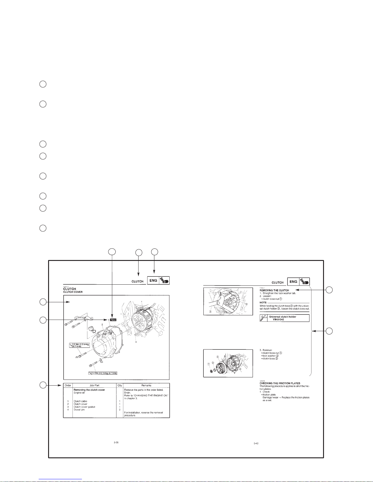
HOW TO USE THIS MANUAL
This manual is intended as a handy , easy-to-read reference book for the mechanic. Comprehensive
explanations of all installation, removal, disassembly , assembly , repair and check procedures are laid
out with the individual steps in sequential order.
1
The manual is divided into chapters. An abbreviation and symbol in the upper right corner of each
page indicate the current chapter. Refer to “SYMBOLS” on the following page.
2
Each chapter is divided into sections. The current section title is shown at the top of each page,
except in Chapter 3 (“Periodic Checks and Adjustments”), where the sub-section title(-s) appears.
(In Chapter 3, “Periodic Checks and Adjustments”, the sub-section title appears at the top of each
page, instead of the section title.)
3
Sub-section titles appear in smaller print than the section title.
4
To help identify parts and clarify procedure steps, there are exploded diagrams at the start of each
removal and disassembly section.
5
Numbers are given in the order of the jobs in the exploded diagram. A circled number indicates a
disassembly step.
6
Symbols indicate parts to be lubricated or replaced (see “SYMBOLS”).
7
A job instruction chart accompanies the exploded diagram, providing the order of jobs, names of
parts, notes in jobs, etc.
8
Jobs requiring more information (such as special tools and technical data) are described sequen-
tially.
6
4
5
7
1
2
3
8
1
GEN
INFO
3
CHK
ADJ
5
COOL
7
2
SPEC
4
ENG
6
CARB
8
ELECCHAS
EAS00008
SYMBOLS
The following symbols are not relevant to every
vehicle.
Symbols
chapter.
General information
1
Specifications
2
Periodic checks and adjustments
3
Engine
4
Cooling system
5
Carburetor(-s)
6
Chassis
7
Electrical system
8
Troubleshooting
9
1
to 9 indicate the subject of each
9
10
TRBL
SHTG
11 12
1413
16 1715
19 2018
22
24 25
Symbols10 to 17 indicate the following.
10
Serviceable with engine mounted
11
Filling fluid
12
Lubricant
13
Special tool
14
Tightening torque
15
Wear limit, clearance
16
Engine speed
17
Electrical data
Symbols18 to 23 in the exploded diagrams indicate the types of lubricants and lubrication
points.
18
Engine oil
19
Gear oil
2321
20
Molybdenum disulfide oil
21
Wheel bearing grease
22
Lithium soap base grease
23
Molybdenum disulfide grease
Symbols24 to 25 in the exploded diagrams indicate the following:
24
Apply locking agent (LOCTITER)
25
Replace the part
EAS00012
TABLE OF CONTENTS
GENERAL INFORMATION
SPECIFICATIONS
PERIODIC CHECKS AND
ADJUSTMENTS
ENGINE
COOLING SYSTEM
GEN
INFO
SPEC
CHK
ADJ
ENG
COOL
1
2
3
4
5
CARBURETORS
CHASSIS
ELECTRICAL SYSTEM
TROUBLESHOOTING
CARB
CHAS
ELEC
TRBL
SHTG
6
7
8
9

GEN
INFO
CHAPTER 1
GENERAL INFORMATION
MOTORCYCLE IDENTIFICATION 1-1. . . . . . . . . . . . . . . . . . . . . . . . . . . . . . .
VEHICLE IDENTIFICATION NUMBER 1-1. . . . . . . . . . . . . . . . . . . . . . . . .
MODEL CODE 1-1. . . . . . . . . . . . . . . . . . . . . . . . . . . . . . . . . . . . . . . . . . . . .
IMPORTANT INFORMATION 1-2. . . . . . . . . . . . . . . . . . . . . . . . . . . . . . . . . . . .
PREPARATION FOR REMOVAL AND DISASSEMBLY 1-2. . . . . . . . . .
REPLACEMENT PARTS 1-2. . . . . . . . . . . . . . . . . . . . . . . . . . . . . . . . . . . . .
GASKETS, OIL SEALS AND O-RINGS 1-2. . . . . . . . . . . . . . . . . . . . . . . .
LOCK WASHERS/PLATES AND COTTER PINS 1-2. . . . . . . . . . . . . . . .
BEARINGS AND OIL SEALS 1-3. . . . . . . . . . . . . . . . . . . . . . . . . . . . . . . . .
CIRCLIPS 1-3. . . . . . . . . . . . . . . . . . . . . . . . . . . . . . . . . . . . . . . . . . . . . . . . . .
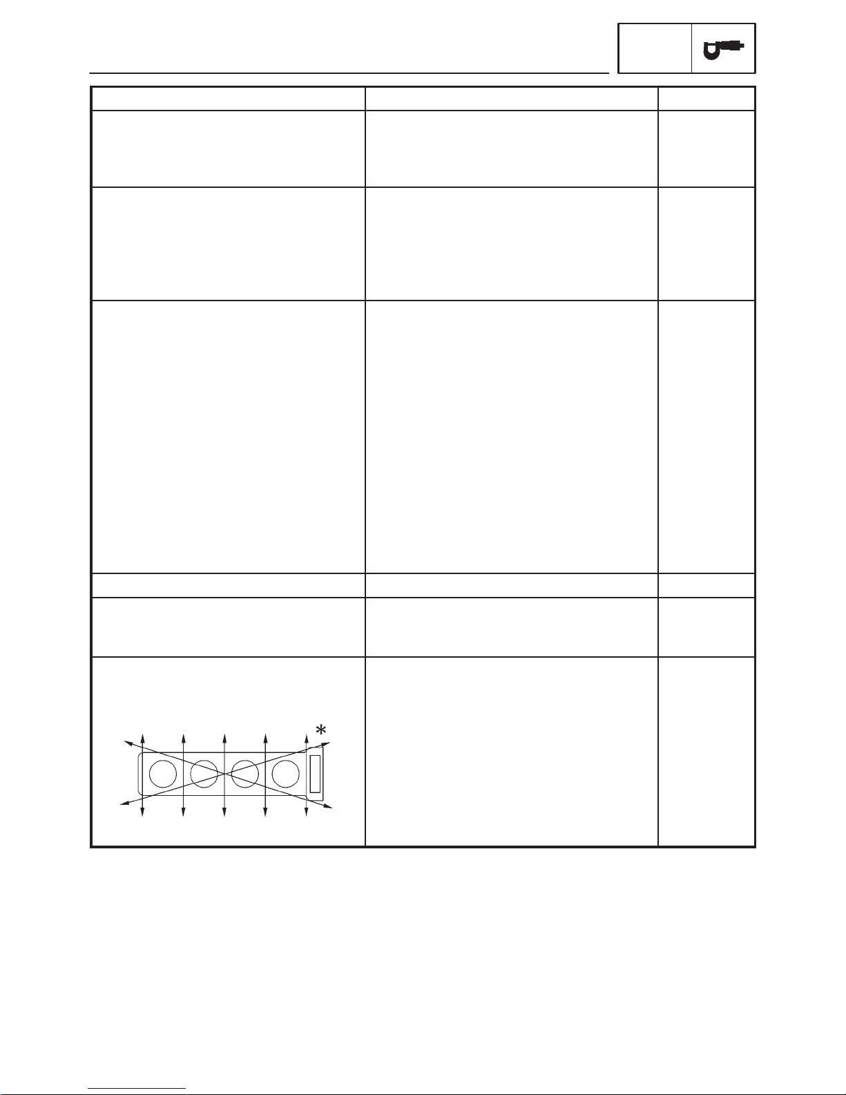
CHECKING THE CONNECTIONS 1-4. . . . . . . . . . . . . . . . . . . . . . . . . . . . . . .
SPECIAL TOOLS 1-5. . . . . . . . . . . . . . . . . . . . . . . . . . . . . . . . . . . . . . . . . . . . . .

GEN
INFO
MOTORCYCLE IDENTIFICATION
EAS00014
GENERAL INFORMATION
MOTORCYCLE IDENTIFICATION
EAS00017
VEHICLE IDENTIFICATION NUMBER
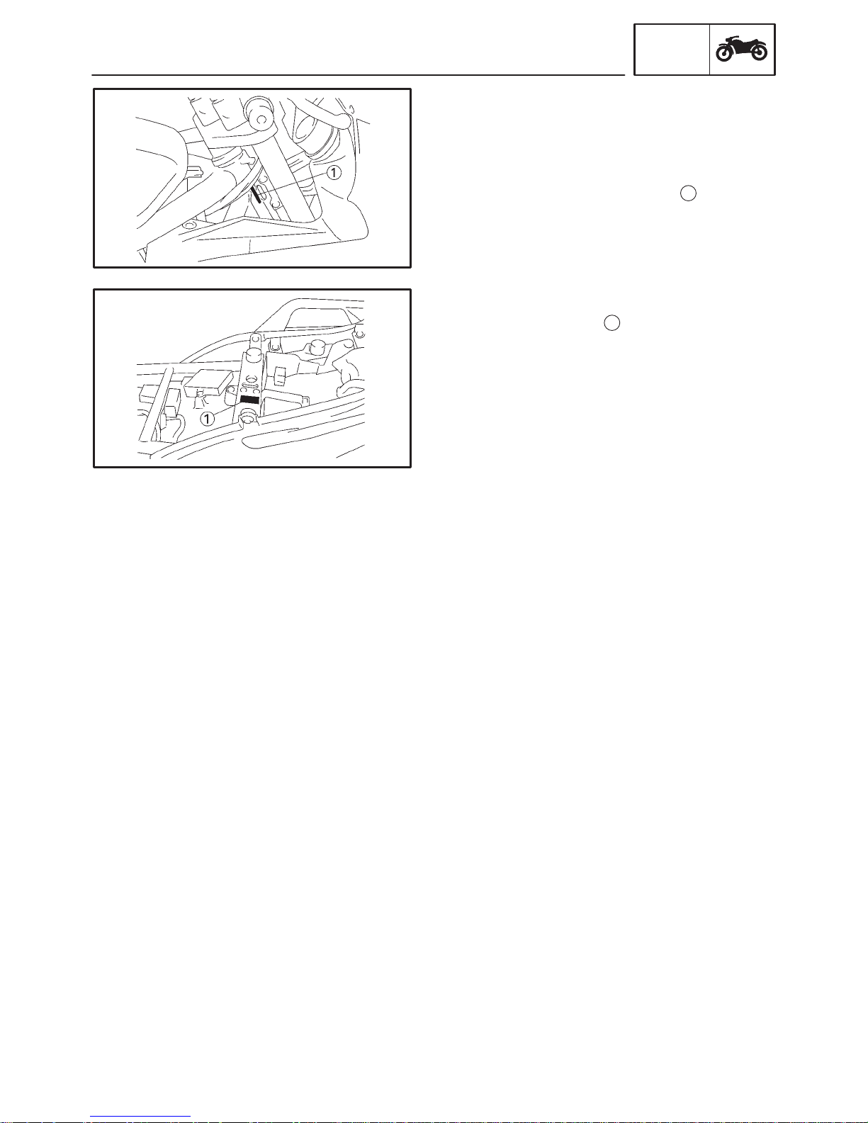
The vehicle identification number
into the right side of the steering head.
EAS00018
MODEL CODE
The model code label
This information will be needed to order spare
parts.
GEN
INFO
1
is stamped
1
is affixed to the frame.
1-1
IMPORTANT INFORMATION
EAS00020
IMPORTANT INFORMATION
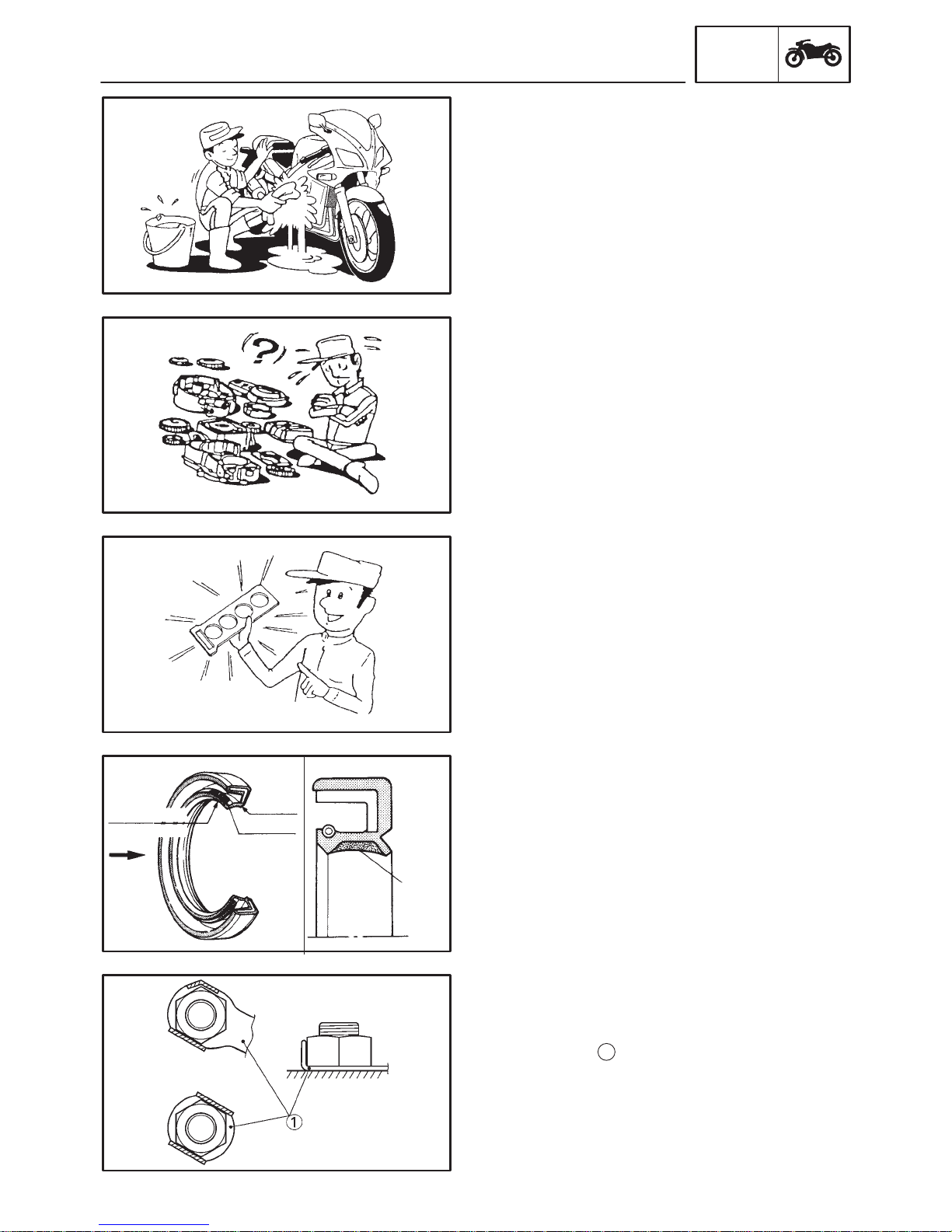
PREPARATION FOR REMOVAL AND DISASSEMBLY
1. Before removal and disassembly , remove all
dirt, mud, dust and foreign material.
2. Use only the proper tools and cleaning
equipment.
Refer to the “SPECIAL TOOLS” section.
3. When disassembling, always keep mated
parts together. This includes gears, cylinders, pistons and other parts that have been
”mated” through normal wear. Mated parts
must always be reused or replaced as an assembly.
4. During disassembly, clean all of the parts
and place them in trays in the order of disassembly . This will speed up assembly and allow for the correct installation of all parts.
5. Keep all parts away from any source of fire.
GEN
INFO
lip
oil
lip
spring
grease
EAS00021
REPLACEMENT PARTS
1. Use only genuine Yamaha parts for all replacements. Use oil and grease recommended by Yamaha for all lubrication jobs.
Other brands may be similar in function and
appearance, but inferior in quality.
EAS00022
GASKETS, OIL SEALS AND O-RINGS
1. When overhauling the engine, replace all
gaskets, seals and O-rings. All gasket surfaces, oil seal lips and O-rings must be
cleaned.
2. During reassembly, properly oil all mating
parts and bearings and apply grease onto
the oil seal lips with greace.
EAS00023
LOCK WASHERS/PLATES AND COTTER
PINS
1. After removal, replace all lock washers/plates
1
and cotter pins. After the bolt or
nut has been tightened to specification, bend
the lock tabs along a flat of the bolt or nut.
1-2
IMPORTANT INFORMATION
EAS00024
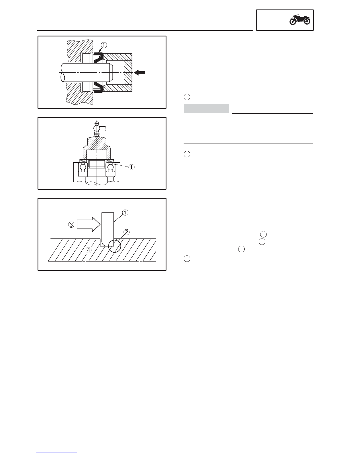
BEARINGS AND OIL SEALS
1. Install bearings and oil seals so that the
manufacturer’s marks or numbers are visible. When installing oil seals, apply a light
coat of lithium soap base grease onto the oil
seal lips. Oil bearings liberally when installing, if appropriate.
Oil seal
1
CAUTION:
Do not spin the bearing with compressed air
because this will damage the bearing surfaces.
Bearing
1
GEN
INFO
EAS00025
CIRCLIPS
1. Before reassembly , check all circlips carefully and replace damaged or distorted circlips.
Always replace piston pin clips after one use.
1
When installing a circlip
the sharp-edged corner
posite the thrust
Shaft
4
3
that the circlip receives.
, make sure that
2
is positioned op-
1-3
CHECKING THE CONNECTIONS
EAS00026
CHECKING THE CONNECTIONS
Check the leads, couplers, and connectors for
stains, rust, moisture, etc.
1. Disconnect:
S lead
S coupler
S connector
2. Check:
S lead
S coupler
S connector
3. Check:
S all connections
NOTE:
If the pin
up.
1
2
3
Moisture ! Dry with an air blower.
Rust/stains ! Connect and disconnect several times.
Loose connection ! Connect properly.
1
on the terminal is flattened, bend it
GEN
INFO
4. Connect:
S lead
S coupler
S connector
NOTE:
Make sure that all connections are tight.
5. Check:
S continuity
(with a pocket tester)
Pocket tester measurement
YU-03112-C
NOTE:
S If there is no continuity, clean the terminals.
S When checking the wire harness, perform
steps 1 to 3.
S As a quick remedy, use a contact revitalizer
available at most part stores.
1-4
GEN
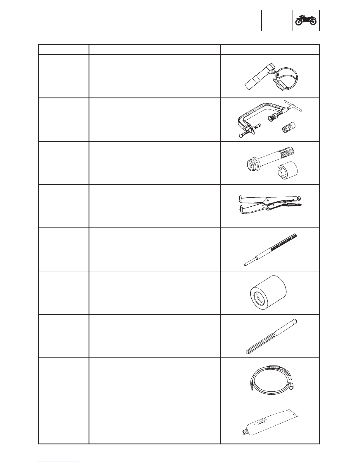
SPECIAL TOOLS
EAS00027
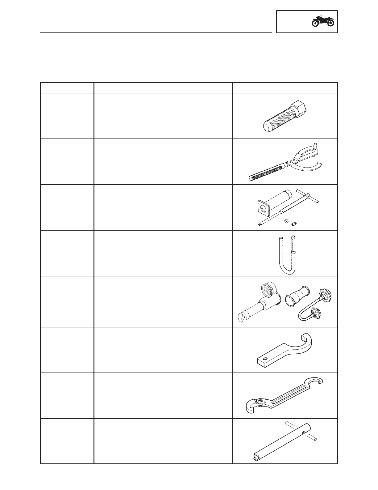
SPECIAL TOOLS
The following special tools are necessary for complete and accurate tune-up and assembly . Use only
the appropriate special tools as this will help prevent damage caused by the use of inappropriate tools
or improvised techniques. Special tools, part numbers or both may differ depending on the country.
When placing an order, refer to the list provided below to avoid any mistakes.
INFO
Tool No.
YM-01080-A
YU-01235
YU-01304
YU-01312-A
Radiator
Pressure Tester
YU-24460-01
Radiator
Pressure
Tester Adapter
YU-33984
Tool name/Function Illustration
Alternator Rotor Puller
This tool is used to remove the generator
rotor.
Universal Magneto & Rotor Holder
This tool is used to hold the generator rotor
when removing or installing the generator
rotor bolt or pickup coil rotor bolt.
Piston Pin Puller
This tool is used to remove the piston pins.
Fuel Level Gauge
This tool is used to measure the fuel level in
the float chamber.
Radiator Pressure Tester
Radiator Pressure Tester Adapter
These tools are used to check the cooling
system.
Spanner Wrench
YU-33975
This tool is used to loosen or tighten the
steering stem ring nuts.
Steering Nut Wrench
YU-1268
This tool is used to loosen the steering stem
ring nuts.
Damper Rod Holder
YM-01447
This tool is used to hold the damper rod
assembly when loosening or tightening the
damper rod assembly bolt.
1-5
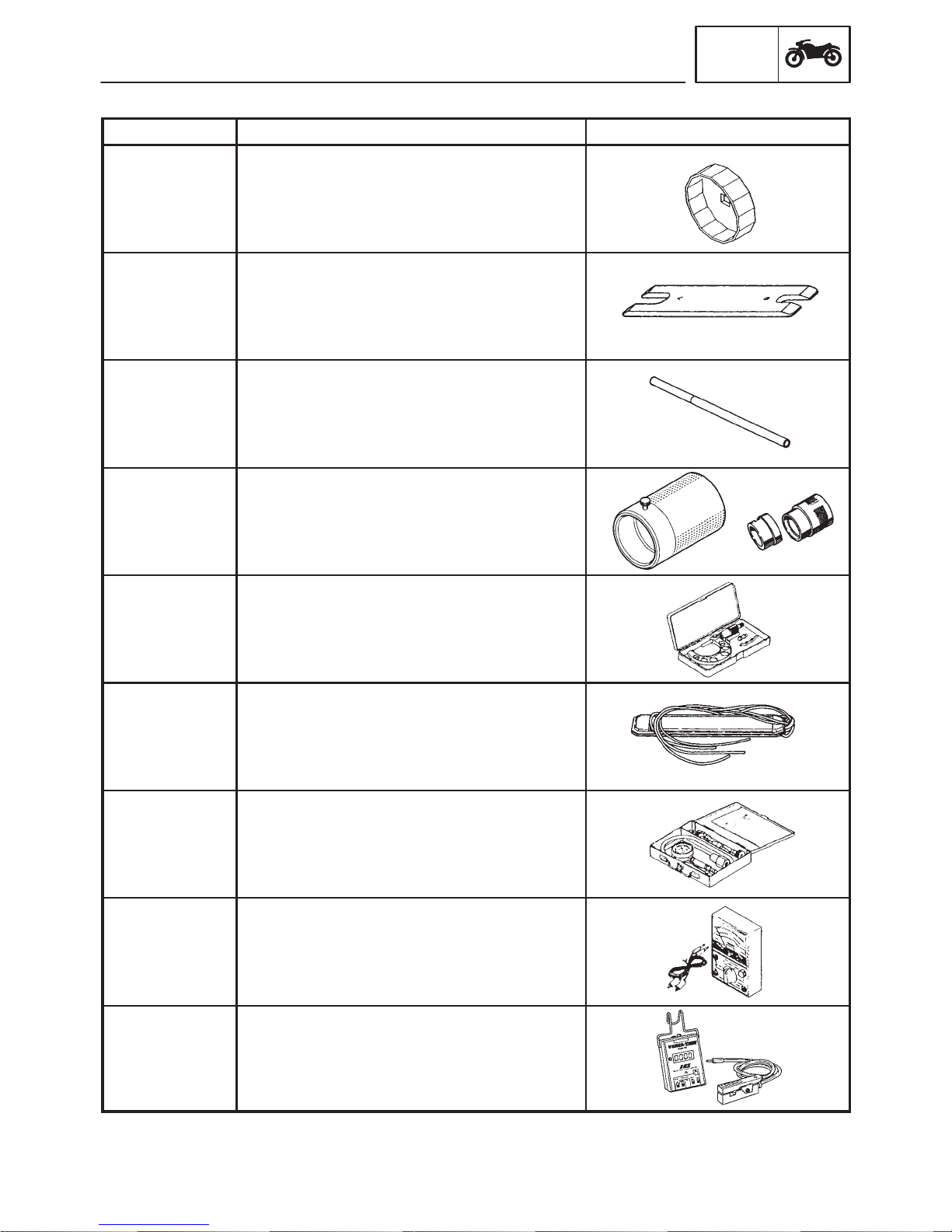
SPECIAL TOOLS
Tool No. Tool name/Function Illustration
Oil Filter Wrench
YU-38411
This tool is needed to loosen or tighten the
oil filter cartridge.
Rod Holder
YM-01434
This tool is used to support the damper
adjusting rod.
Rod Puller
Rod puller
YM-01437
This tool is used to pull up the front fork
damper rod.
GEN
INFO
Driver
YM-33963
43 mm
Adapters
YM-8020-A
YU-03008
YU-8030
Compression
Gauge Set
YU-33223
Driver
43 mm Adapters
This tool is used to install the front fork’s oil
seal and dust seal.
Micrometers (50 X 75 mm)
This tool is used to measure the piston skirt
diameter.
Carburetor Synchronizer
This guide is used to synchronize the
carburetors.
Compression Gauge Set
Compression Gauge Adapter
These tools are used to measure engine
compression.
Pocket Tester Measurement
YU-03112-C
This tool is used to check the electrical
system.
Inductive Self-Powered Tachometer
YU-8036-B
This tool is used to check engine speed.
1-6
SPECIAL TOOLS
Tool No. Tool name/Function Illustration
Battery Powered Timing Light
YM-33277-A
This tool is used to check the ignition
timing.
Valve Spring
Compressor
YM-04019
Adapter
YM-4108
YM-4114
40 and 50 mm
Bearing Driver
YM-4058
Water Pump
Seat Installer
YM-33221
Valve Spring Compressor Set, Quick
Release
Adapter
These tools are used to remove or install
the valve assemblies.
40 and 50 mm Bearing Driver
Water Pump Seal Installer
These tools are used to install the water
pump seal.
Universal Clutch Holder (Grabbit)
GEN
INFO
YM-91042
YM-04111
YM-4116
YM-04112
YM-4117
YM-04113
YM-4118
This tool is used to hold the clutch boss
when removing or installing the clutch boss
nut.
Valve Guide Remover (ø4)
Valve Guide Remover (ø4.5)
This tool is used to remove or install the
valve guides.
Valve Guide Installer (ø4)
Valve Guide Installer (ø4.5)
This tool is used to install the valve guides.
Valve Guide Reamer (ø4)
Valve Guide Reamer (ø4.5)
This tool is used to rebore the new valve
guides.
Dynamic Spark Tester
YM-34487
This tool is used to check the ignition
system components.
Yamaha bond No. 1215
ACC-1100105-01
This bond is used to seal two mating
surfaces (e.g., crankcase mating surfaces).
1-7


SPEC
CHAPTER 2.
SPECIFICATIONS
GENERAL SPECIFICATIONS 2-1. . . . . . . . . . . . . . . . . . . . . . . . . . . . . . . . . . .
ENGINE SPECIFICATIONS 2-2. . . . . . . . . . . . . . . . . . . . . . . . . . . . . . . . . . . . .
CHASSIS SPECIFICATIONS 2-11. . . . . . . . . . . . . . . . . . . . . . . . . . . . . . . . . . . .
ELECTRICAL SPECIFICATIONS 2-15. . . . . . . . . . . . . . . . . . . . . . . . . . . . . . . .
TIGHTENING TORQUES 2-18. . . . . . . . . . . . . . . . . . . . . . . . . . . . . . . . . . . . . . .
GENERAL TIGHTENING TORQUES 2-18. . . . . . . . . . . . . . . . . . . . . . . . . .
ENGINE TIGHTENING TORQUES 2-19. . . . . . . . . . . . . . . . . . . . . . . . . . . .
CHASSIS TIGHTENING TORQUES 2-22. . . . . . . . . . . . . . . . . . . . . . . . . . .
LUBRICATION POINTS AND LUBRICANT TYPES 2-23. . . . . . . . . . . . . . . .
ENGINE 2-23. . . . . . . . . . . . . . . . . . . . . . . . . . . . . . . . . . . . . . . . . . . . . . . . . . .
CHASSIS 2-24. . . . . . . . . . . . . . . . . . . . . . . . . . . . . . . . . . . . . . . . . . . . . . . . . .
COOLING SYSTEM DIAGRAMS 2-25. . . . . . . . . . . . . . . . . . . . . . . . . . . . . . . .
ENGINE OIL LUBRICATION CHART 2-29. . . . . . . . . . . . . . . . . . . . . . . . . . . . .
LUBRICATION DIAGRAMS 2-30. . . . . . . . . . . . . . . . . . . . . . . . . . . . . . . . . . . . .
CABLE ROUTING 2-35. . . . . . . . . . . . . . . . . . . . . . . . . . . . . . . . . . . . . . . . . . . . .
SPEC
GENERAL SPECIFICATIONS
SPECIFICATIONS
GENERAL SPECIFICATIONS
Item Standard Limit
Model code 5LV5 (USA except for California)
5LV6 (CDN)
5LV7 (California)
Dimensions
Overall length
Overall width
Overall height
Seat height
Wheelbase
Minimum ground clearance
Minimum turning radius
Weight
Wet (with oil and a full fuel tank)
Dry (without oil and fuel)
Maximum load (total of cargo, rider,
passenger, and accessories)
2,125 mm (83.7 in)
765 mm (30.1 in)
1,190 mm (46.9 in)
820 mm (32.3 in)
1,450 mm (57.1 in)
140 mm (5.5 in)
2,900 mm (114.2 in)
231 kg (509 lb)
232 kg (512 lb) (for california)
208 kg (459 lb)
209 kg (461 lb) (for california)
189 kg (417 lb)
188 kg (415 lb) (for california)
SPEC
2-1
ENGINE SPECIFICATIONS
Item Standard Limit
Engine
Engine type
Displacement
Cylinder arrangement
Bore X stroke
Compression ratio
Engine idling speed
Vacuum pressure at engine idling
speed
Standard compression pressure
(at sea level)
Fuel
Recommended fuel
Fuel tank capacity
Total (including reserve)
Reserve only
Engine oil
Lubrication system
Recommended oil
ENGINE SPECIFICATIONS
SPEC
Liquid-cooled, 4-stroke, DOHC
998 cm
3
Forward-inclined parallel 4-cylinder
74 X 58 mm (2.91 X 2.28 in)
11.4 : 1
1,050 X 1,150 r/min
30 kPa (225 mmHg, 8.86 in Hg)
1,450 kPa
2
(14.5 kg/cm
, 206 psi) at 400 r/min
Unleaded fuel (for USA)
Regular unleaded gasoline (for CDN)
21 L (18.5 Imp qt, 22.2 US qt)
4.0 L (3.52 Imp qt, 4.22 US qt)
Wet sump
Yamalube 4 (20W40) or SAE 20W40 type
SE motor oil
Quantity
Total amount
Without oil filter cartridge
replacement
With oil filter cartridge
replacement
Oil pressure (hot)
Relief valve opening pressure
3.7 L (3.2 Imp qt, 3.8 US qt)
2.8 L (2.4 Imp qt, 2.9 US qt)
3.0 L (2.6 Imp qt, 3.1 US qt)
2
45 kPa (0.45 kg/cm
, 6.40 psi) at
1,100 r/min
490 X 570 kPa
2
(4.9 X 5.7 kg/cm
, 69.7 X 81.1 psi)
2-2
ENGINE SPECIFICATIONS
Item Standard Limit
Oil filter
Oil filter type
Bypass valve opening pressure
Oil pump
Oil pump type
Inner-rotor-to-outer-rotor-tip
clearance
Outer-rotor-to-oil-pump-housing
clearance
Cooling system
Radiator capacity
Radiator cap opening pressure
Radiator core
Width
Height
Depth
Coolant reservoir
Capacity
Water pump
Water pump type
Reduction ratio
Max. impeller shaft tilt
Starting system type Electric starter
Cartridge (paper)
180 X 220 kPa
(1.8 X 2.2 kg/cm
Trochoidal
0.09 X 0.15 mm (0.004 X 0.006 in)
0.03 X 0.08 mm (0.001 X 0.003 in)
2.4 L (2.11 Imp qt, 2.53 US qt)
95 X 125 kPa
(0.95 X 1.25 kg/cm
340 mm (13.4 in)
238 mm (9.4 in)
24 mm (0.94 in)
0.3 L (0.26 Imp qt, 0.32 US qt)
Single-suction centrifugal pump
68/43 X 28/28 (1.581)
2
, 25.6 X 31.3 psi)
2
, 13.1 X 17.8 psi)
SPEC
0.15 mm
(0.006 in)
Spark plugs
Model (manufacturer) X quantity
Spark plug gap
Cylinder head
Max. warpage
CR9E/U27ESR-N (NGK/DENSO) X 4
0.7 X 0.8 mm (0.028 X 0.031 in)
0.1 mm
(0.004 in)
2-3
Item Standard Limit
Camshafts
Drive system
Camshaft cap inside diameter
Camshaft journal diameter
Camshaft-journal-to-camshaft-
cap clearance
Intake camshaft lobe dimensions
ENGINE SPECIFICATIONS
Chain drive (right)
24.500 X 24.521 mm
(0.9646 X 0.9654 in)
24.459 X 24.472 mm
(0.9630 X 0.9635 in)
0.028 X 0.062 mm (0.0011 X 0.0024 in)
SPEC
Measurement A
Measurement B
Measurement C
Exhaust camshaft lobe
dimensions
Measurement A
Measurement B
Measurement C
Max. camshaft runout
32.5 X 32.6 mm (1.2795 X 1.2835 in)
24.95 X 25.05 mm (0.9823 X 0.9862 in)
7.45 X 7.65 mm (0.2933 X 0.3012 in)
32.95 X 33.05 mm (1.2972 X 1.3012 in)
24.95 X 25.05 mm (0.9823 X 0.9862 in)
7.75 X 7.95 mm (0.3051 X 0.3126 in)
32.4 mm
(1.2756 in)
24.85 mm
(0.9783 in)
32.85 mm
(1.2933 in)
24.85 mm
(0.9783 in)
0.03 mm
(0.0012 in)
2-4
ENGINE SPECIFICATIONS
Intake
0.21 X 0.25 mm (0.0083 X 0.0098 in)
Item Standard Limit
Timing chain
Model/number of links
Tensioning system
Valves, valve seats, valve guides
Valve clearance (cold)
Exhaust
Valve dimensions
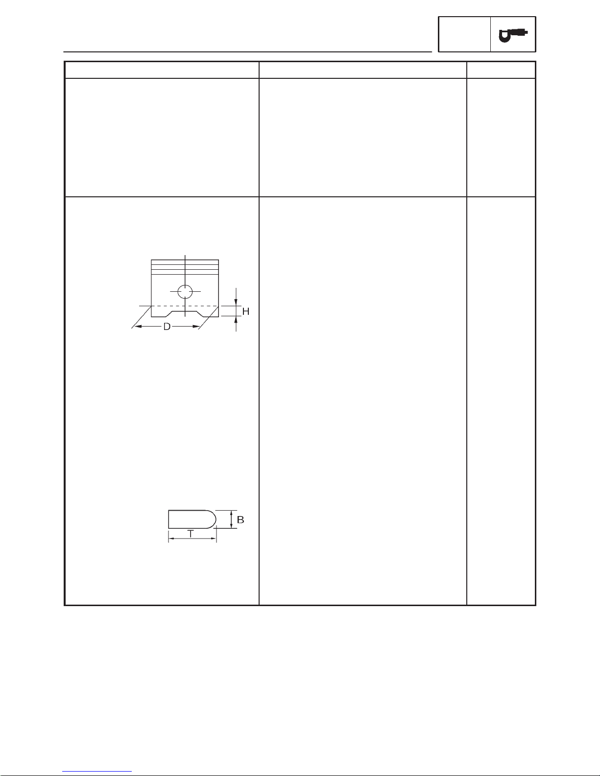
Head Diameter Face Width Seat Width Margin Thickness
Valve head diameter A
Intake
Exhaust
Valve face width B
Intake
Exhaust
Valve seat width C
Intake
Exhaust
Valve margin thickness D
Intake
Exhaust
Valve stem diameter
Intake
Exhaust
Valve guide inside diameter
Intake
Exhaust
Valve-stem-to-valve-guide
clearance
Intake
Exhaust
RH2015/130
Automatic
0.11 X 0.20 mm (0.0043 X 0.0079 in)
X
22.9 X 23.1 mm (0.9016 X 0.9094 in)
24.4 X 24.6 mm (0.9606 X 0.9685 in)
1.76 X 2.90 mm (0.0693 X 0.1142 in)
1.76 X 2.90 mm (0.0693 X 0.1142 in)
0.9 X 1.1 mm (0.035 X 0.043 in)
0.9 X 1.1 mm (0.035 X 0.043 in)
0.5 X 0.9 mm (0.020 X 0.035 in)
0.5 X 0.9 mm (0.020 X 0.035 in)
3.975 X 3.900 mm (0.1565 X 0.1535 in)
4.465 X 4.480 mm (0.1758 X 0.1764 in)
4.000 X 4.012 mm (0.1575 X 0.1580 in)
4.500 X 4.512 mm (0.1772 X 0.1776 in)
0.010 X 0.037 mm (0.0004 X 0.0015 in)
0.020 X 0.047 mm (0.0008 X 0.0019 in)
X
SPEC
3.945 mm
(0.1553 in)
4.43 mm
(0.1744 in)
4.05 mm
(0.1594 in)
4.55 mm
(0.1791 in)
0.08 mm
(0.0031 in)
0.10 mm
(0.0039 in)
2-5
ENGINE SPECIFICATIONS
Item Standard Limit
SPEC
Valve stem runout
Valve seat width
Intake
Exhaust
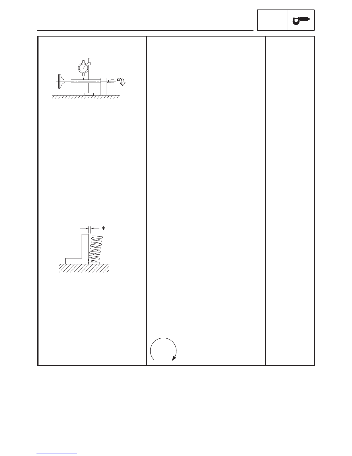
Valve springs
Free length
Intake
Exhaust
Installed length (valve closed)
Intake
Exhaust
Compressed spring force
(installed)
Intake
Exhaust
Spring tilt
SSS
0.9 X 1.1 mm (0.035 X 0.043 in)
0.9 X 1.1 mm (0.035 X 0.043 in)
38.90 mm (1.53 in)
40.67 mm (1.60 in)
34.50 mm (1.36 in)
35.00 mm (1.38 in)
82 X 96 N (8.2 X 9.6 kg, 18.4 X 25.4 lb)
110 X 126 N
(11.0 X 12.6 kg, 24.7 X 28.3 lb)
0.01 mm
(0.0004 in)
SSS
SSS
SSS
SSS
SSS
SSS
SSS
SSS
Intake
Exhaust
Winding direction (top view)
Intake
Exhaust
SSS
SSS
Clockwise
Clockwise
2-6
2.5_ /1.7 mm
(2.5_ /0.067 in)
2.5_ /1.8 mm
(2.5_ /0.071 in)
SSS
SSS
Item Standard Limit
Cylinders
Cylinder arrangement
Bore X stroke
Compression ratio
Bore
Max. taper
Max. out-of-round
Pistons
Piston-to-cylinder clearance
Diameter D
ENGINE SPECIFICATIONS
Forward-inclined, parallel 4-cylinder
74 X 58 mm (2.91 X 2.28 in)
11.4 : 1
74.00 X 74.01 mm (2.9134 X 2.9138 in)
0.030 X 0.055 mm (0.001 X 0.002 in)
73.955 X 73.970 mm
(2.9118 X 2.9122 in)
SPEC
0.05 mm
(0.0016 in)
0.05 mm
(0.0016 in)
0.12 mm
(0.005 in)
Height H
Piston pin bore (in the piston)
Diameter
Offset
Offset direction
Piston pins
Outside diameter
Piston-pin-to-piston-pin-bore
clearance
Piston rings
Top ring
Ring type
Dimensions (B X T)
End gap (installed)
Ring side clearance
5 mm (0.20 in)
17.002 X 17.013 mm
(0.6694 X 0.6698 in)
0.5 mm (0.0197 in)
Intake side
16.991 X 17.000 mm
(0.6689 X 0.6693 in)
0.002 X 0.022 mm
(0.00008 X 0.00087 in)
Barrel
0.90 X 2.75 mm (0.035 X 0.108 in)
0.32 X 0.44 mm (0.010 X 0.020 in)
0.030 X 0.065 mm (0.0012 X 0.0026 in)
17.043 mm
(0.6710 in)
16.971 mm
(0.6681 in)
0.072 mm
(0.0028 in)
2-7
2nd ring
ENGINE SPECIFICATIONS
Item Standard Limit
SPEC
Ring type
Dimensions (B X T)
End gap (installed)
Ring side clearance
Oil ring
Dimensions (B X T)
End gap (installed)
Connecting rods
Crankshaft-pin-to-big-end-bearing
clearance
Bearing color code
Crankshaft
Taper
0.8 X 2.8 mm (0.031 X 0.110 in)
0.43 X 0.58 mm (0.017 X 0.023 in)
0.020 X 0.055 mm (0.0008 X 0.0022 in)
1.5 X 2.6 mm (0.059 X 0.101 in)
0.10 X 0.35 mm (0.004 X 0.014 in)
0.031 X 0.055 mm (0.0012 X 0.0022 in)
–1 = Violet 0 = White 1 = Blue
2 = Black
Width A
Width B
Max. runout C
Big end side clearance D
Crankshaft-journal-to-crankshaftjournal-bearing clearance
Bearing color code
Clutch
Clutch type
Clutch release method
Clutch release method operation
Operation
Clutch cable free play (at the end of the
clutch lever)
52.40 X 57.25 mm (2.063 X 2.254 in)
300.75 X 302.65 mm (11.84 X 11.92 in)
0.03 mm
(0.0012 in)
0.160 X 0.262 mm (0.006 X 0.010 in)
0.029 X 0.053 mm (0.0011 X 0.0021 in)
–1 = Pink/violet 0 = Pink/white
1 = Pink/blue 2 = Pink/black
3 = Pink/brown
Wet, multiple disc
Cam (pull rod type)
Cable operation
Left-hand operation
10 X 15 mm (0.39 X 0.59 in)
2-8
Item Standard Limit
Friction plates
Thickness
Plate quantity
Thickness
Plate quantity
Clutch plates
Thickness
Plate quantity
Max. warpage
Clutch springs
Free length
Spring quantity
Transmission
Transmission type
Primary reduction system
Primary reduction ratio
Secondary reduction system
Secondary reduction ratio
Operation
Gear ratios
1st gear
2nd gear
3rd gear
4th gear
5th gear
6th gear
Max. main axle runout
Max. drive axle runout
ENGINE SPECIFICATIONS
2.92 X 3.08 mm (0.115 X 0.121 in)
8
3.42 X 3.58 mm (0.135 X 0.141 in)
1
1.9 X 2.1 mm (0.075 X 0.083 in)
8
50 mm (1.97 in)
6
Constant mesh, 6-speed
Spur gear
68/43 (1.581)
Chain drive
44/16 (2.750)
Left-foot operation
35/14 (2.500)
35/19 (1.842)
30/20 (1.500)
28/21 (1.333)
30/25 (1.200)
29/26 (1.115)
SPEC
2.82 mm
(0.111 in)
3.32 mm
(0.131 in)
0.1 mm
(0.004 in)
0.08 mm
(0.003 in)
0.08 mm
(0.003 in)
Shifting mechanism
Shift mechanism type
Max. shift fork guide bar bending
Installed shift rod length
Air filter type Dry element
Fuel pump
Pump type
Model (manufacturer)
Output pressure
Guide bar
260 mm (10.2 in)
Electrical
4SV (MITSUBISHI)
20 kPa (0.2 kg/cm
2-9
2
, 2.8 psi)
0.1 mm
(0.004 in)
Item Standard Limit
Carburetors
Model (manufacturer) X quantity
Throttle cable free play (at the
flange of the throttle grip)
ID mark
Main jet
Main air jet
Jet needle
Needle jet
Pilot air jet
Pilot outlet
Pilot jet
Bypass 1
Bypass 2
Bypass 3
Pilot screw turns out
Valve seat size
Starter jet 1
Starter jet 2
Throttle valve size
Fuel level (above the line on the
float chamber)
ENGINE SPECIFICATIONS
BSR37 (MIKUNI) X 4
3 X 5 mm (0.12 X 0.20 in)
5LV5 40
Carburetors 1 and 4: #132.5
Carburetors 2 and 3: #130
#80
Carburetor 1 and 4: 5D129-3/5
Carburetor 2 and 3: 5D130-3/5
P-OM
#85
1.0
#15
0.9
0.9
0.9
2.0
1.5
#42.5
0.8
#115
3.0 X 4.0 mm (0.118 X 0.157 in)
SPEC
Max. EXUP cable free play (at the
EXUP valve pulley)
1.5 mm (0.059 in)
2-10
CHASSIS SPECIFICATIONS
Item Standard Limit
Frame
Frame type
Caster angle
Trail
Front wheel
Wheel type
Rim
Size
Material
Wheel travel
Wheel runout
Max. radial wheel runout
Max. lateral wheel runout
Rear wheel
Wheel type
Rim
Size
Material
Wheel travel
Wheel runout
Max. radial wheel runout
Max. lateral wheel runout
CHASSIS SPECIFICATIONS
Double cradle
26_
104 mm (4.09 in)
Cast wheel
17 X MT3.50
Aluminum
140 mm (5.51 in)
SSS
SSS
Cast wheel
17 X MT5.50
Aluminum
135 mm (5.31 in)
SSS
SSS
SPEC
SSS
SSS
SSS
SSS
SSS
SSS
SSS
1 mm
(0.04 in)
0.5 mm
(0.02 in)
SSS
SSS
SSS
SSS
1 mm
(0.04 in)
0.5 mm
(0.02 in)
Front tire
Tire type
Size
Model (manufacturer)
Tire pressure (cold)
0 X 90 kg
90 X 201 kg
High-speed riding
Min. tire tread depth
Tubeless
120/70 ZR17 (58W)
MEZ4Y FRONT (METZELER)
BT020F U (BRIDGESTONE)
2
250 kPa (2.5 kgf/cm
250 kPa (2.5 kgf/cm
250 kPa (2.5 kgf/cm
, 36 psi)
2
, 36 psi)
2
, 36 psi)
SSS
SSS
SSS
SSS
SSS
SSS
SSS
1.0 mm
(0.04 in)
2-11
 Loading...