

Page 1

Page 2
FOREWORD
This Assembly Manual contains the information required for the correct reassembly of this Y amaha motorcycle prior to delivery to the customer. Since some external parts of the motorcycle have been removed at the
Y amaha factory for the convenience of packing, assembly by the Y amaha dealer is required. It should be noted
that the reassembled motorcycle should be throughly
cleaned, inspected, and adjusted prior to delivery to the
customer.
NOTICE
The service specifications given in this assembly manual are based on the model as manufactured. Modifications and significant changes in specifications and / or
procedures will be forwarded to Authorized Yamaha
Dealers. The procedures below are described in the order that the procedures are carried out correctly and
completely.Failure to do so can result in poor performance and possible harm to the motorcycle and/or rider.
Particularly important information is distinguished in this
manual by the following notations.
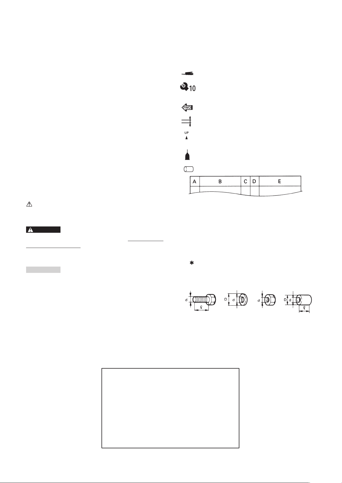
SYMBOLS USED IN
ASSEMBLY MANUAL
In order to simplify descriptions in assembly manuals,
the following symbols are used:
: Coat with lithium soap base grease.
: Tighten to 10 Nm.
: (10 Nm = 1.0 mkg)
: Front ward of the motorcycle.
: Provide a clearance.
: Install so that the arrow mark faces
: upward.
: Apply a motor oil.
: Made of rubber or plastics.
The Safety Alert Symbol means ATTENTION! BECOME ALERT! YOUR SAFETY IS INVOLVED!
WARNING
Failure to follow WARNING instructions could result in
severe injury or death to the motorcycle operator, a bystander, or a person inspecting or repairing the motorcycle.
CAUTION:
A CAUTION indicates special precautions that must be
taken to avoid damage to the motorcycle.
NOTE:
A NOTE provides key information to make procedures
easier or clearer.
A: Ref No. (indicating the order or operations.)
B: Part name
C: Quantity of parts per motorcycle.
D: Place where parts are held.
V: Stored in vinyl bag.
C: Stored in carton box.
S: Fixed inside the steel frame and/or contained
in the styrofoam tray (upper or lower).
: Temporarily installed or secured.
E: Size or material of parts.
d/D:Diameter of part.
: Length of part.
ex, 5 = 5 mm
FZS1000 (N) 2001
ASSEMBLY MANUAL
2000 by Yamaha Motor Co., Ltd.
First Edition, December 2000
All rights reserved. Any reproduction or
unauthorized use without the written
permission of Yamaha Motor Co., Ltd.
is expressly prohibited.
Printed in BELGIUM
Page 3

FZS1000 (N) 2001
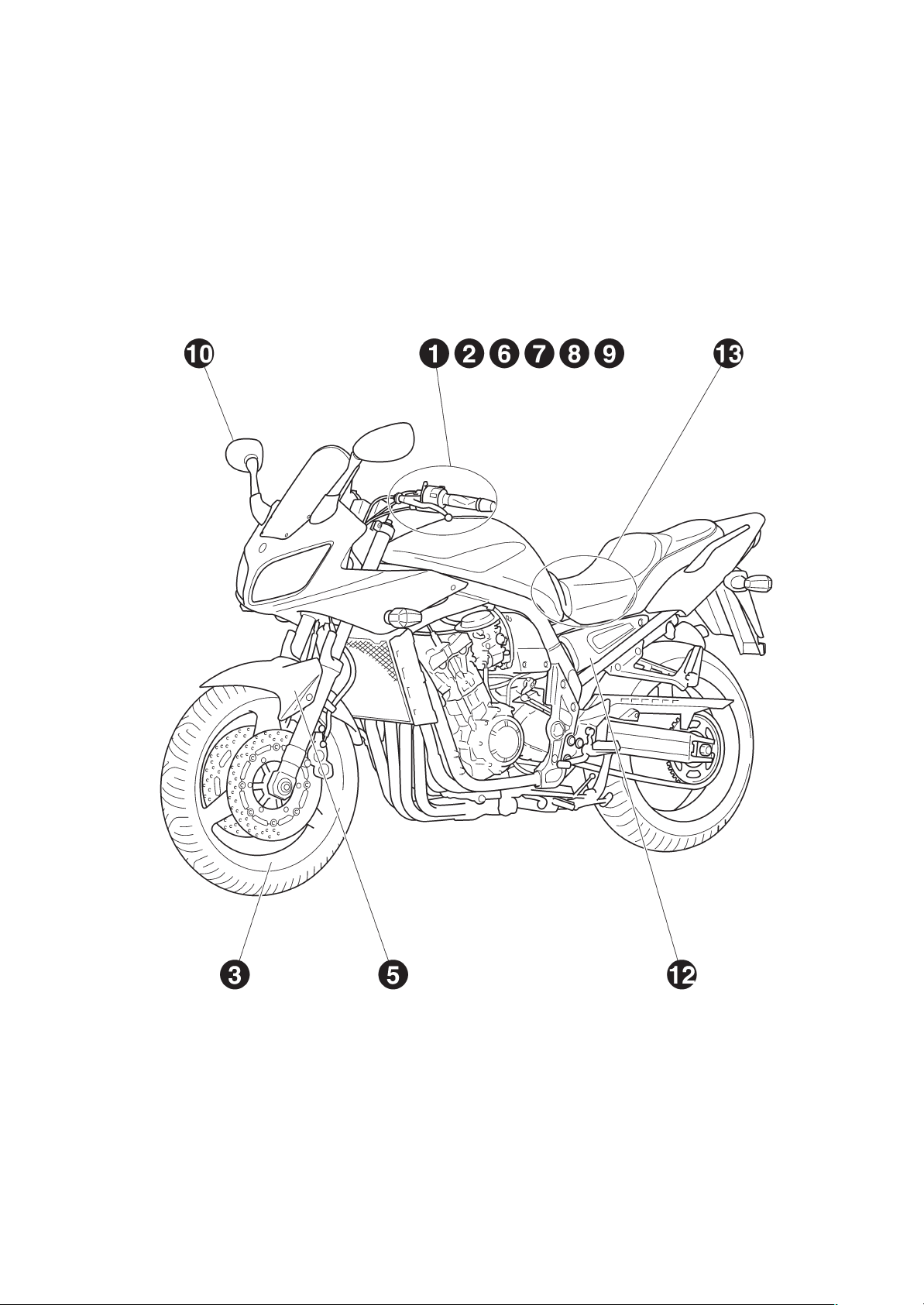
SET-UP AND PREDELIVERY CHECKLIST
NOTE:
Check the following items again when set up and predelivery service are completed.
A: INSTALLATION OF THE PARTS INCLUDED IN THE CRATE
Handlebar
Throttle grip
Front wheel
Front fender
Front brake hose clamp
Front brake master cylinder
Handlebar switch (left)
B: TIGHTENING TORQUE OF EACH PART
Handlebar holder (upper) 28 Nm (2.8 mkg)
Front fender and outer tube 10 Nm (1.0 mkg)
Front wheel axle 59 Nm (5.9 mkg)
Front wheel axle pinch bolt 20 Nm (2.0 mkg)
Master cylinder and bracket 10 Nm (1.0 mkg)
Side cover 4 Nm (0.4 mkg)
C: ROUTING OF WIRE, CABLES, ETC.
Throttle cables
Brake hose
Clutch cable
Left handlebar switch lead
Clutch cable
Band
Rear view mirror
Windscreen
Inner panel
Side cover (left)
Battery
Right handlebar switch lead
Battery positive lead
Battery negative lead
Starter cable
D: ADJUSTMENTS
Checking and charging the battery
Drain the fuel
Checking the tire pressure
Checking the engine oil level
Checking the coolant level
Adjusting the engine idling speed
Adjusting the throttle cable free play
Adjusting the front brake
Adjusting the rear brake
Checking the brake fluid level
Breeding the hydraulic brake system
Adjusting the clutch cable free play
Adjusting the front fork legs
Adjusting the rear shock absorber assembly
Adjusting the drive chian slack
Adjusting the rear brake light switch
Adjusting the headlight beams
Adjusting the digital clock
Page 4

E: FUNCTION AND PERFORMANCE
Check for the function of headlight, meter light and tail light
Check for the funciton of brake light
Check for the function of flasher light and indicator light
Check for the tone quality of the horn
Check for the function of the indicator on the speedometer
Check for brake feeling
Check for engine noise (Yes/No)
Check for exhaust leak (Yes/No)
F: ACCESSORIES, ETC. FOR DELIVERY
Owner’s manual
Owner’s tool kit
Page 5
SETUP PROCEDURES
–1–
Page 6
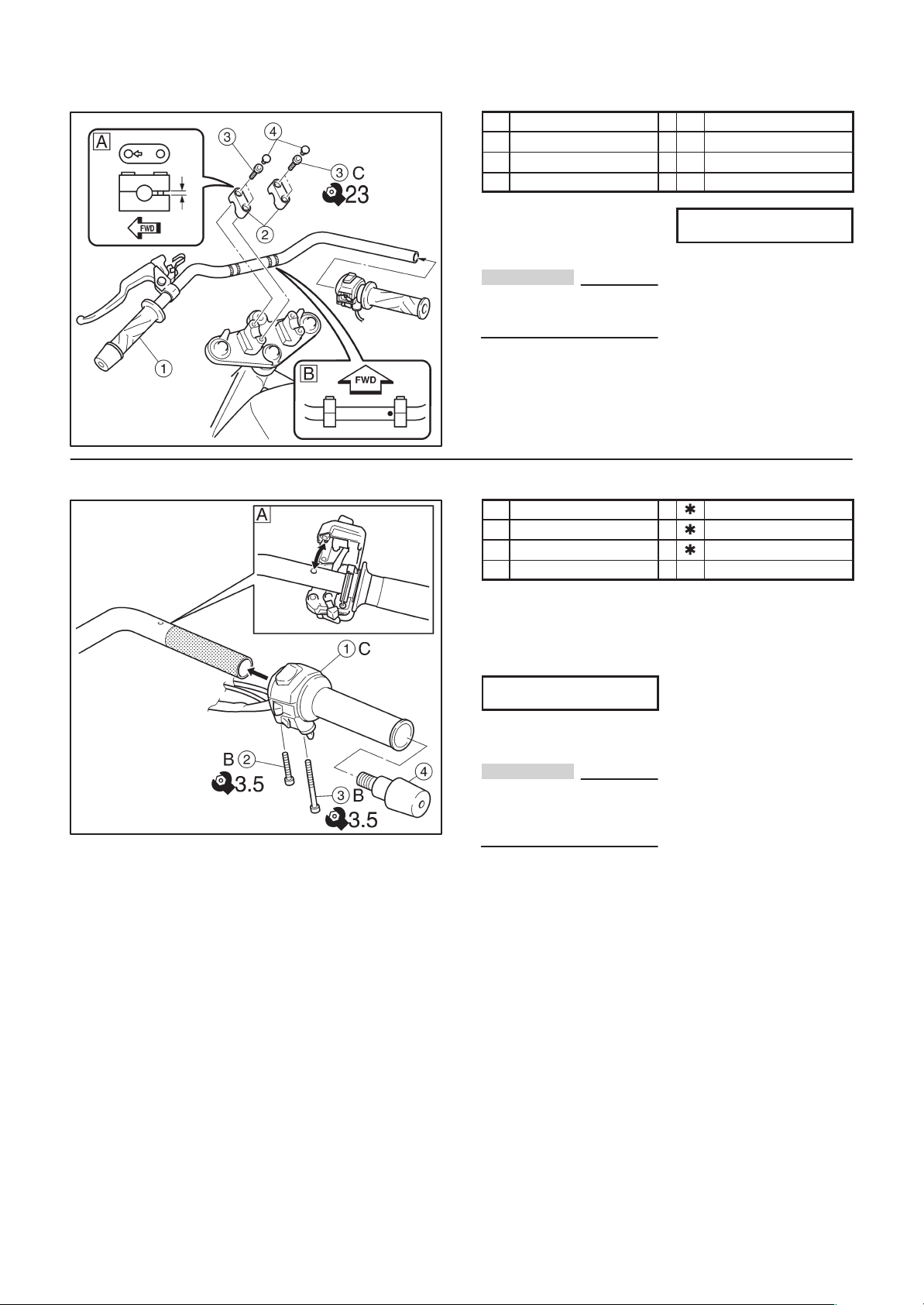
1. Handlebar
1 Handlebar 1 C
2 Handlebar holder 2 V
3 Hexagon socket bolt 4 V d = 8, = 30
4 Plug 4 V
2. Throttle grip
A: The handlebar holder should be
installed with the arrow mark
forward.
Tightening torque:
23 Nm (2.3 mkg)
CAUTION:
First tighten the bolts on the
front side, and then tighten the
bolts on the rear side.
B: Align the punch mark on the
handlebar with the top of the
lower handlebar holder.
C: Tighten the bolts to specified
torque.
1 Throttle grip 1
2 Screw 1 d = 5, = 30
3 Screw 1 d = 5, = 50
4 Grip end 1 V
A: Align the projection on the han-
dlebar switch with the hole in
the handlebar.
B: Tighten the bolt to specified
torque.
Tightening torque
3.5 Nm (0.4 mkg)
C: Check the throttle grip for
smooth action.
CAUTION:
Proper cable routing is essential
to assure safe motorcycle operation.
Refer to “CABLE ROUTING”.
–2–
Page 7
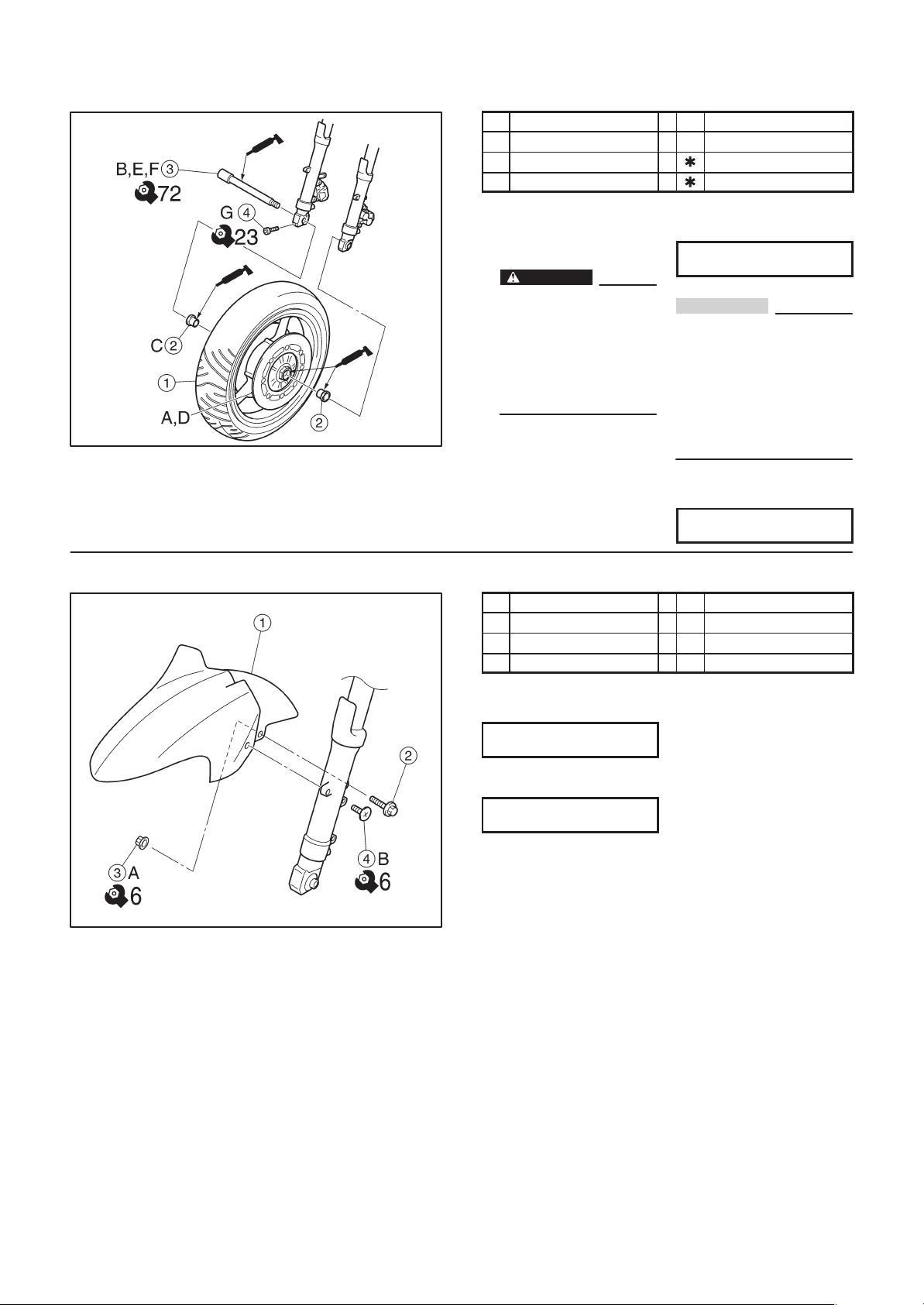
3. Front wheel
1 Front wheel 1 S
2 Collar 2 V
3 Front wheel axle 1
4 Axle pinch bolt 1 d = 8, = 45
4. Front fender
A: Clean the brake disc.
B: Clean the front wheel axle.
C: Clean the collar .
D:
WARNING
Take care not to put grease
on the brake disc or inner
surface of the brake pads. If
you do so, clean using a rag
dampened with a solvent.
Foreign material on braking
surface can cause impaired
braking action.
E: Lift the front wheel and install
the front wheel axle.
1 Front fender 1 C
2 Flange bolt 2 V d = 6, = 9
3 Nut 2 V d = 6
4 Screw 2 V d = 6, = 61
F: Tighten the front wheel axle to
specified torque.
Tightening torque:
72 Nm (7.2 mkg)
CAUTION:
Before tightening the pinch bolt,
stroke the front forks several
times to make sure of proper fork
operation. With the pinch bolt
loose, work the left fork leg back
and forth until the proper clearance between the disc and caliper bracket on the front fork are
obtained.
G: Tighten the axle pinch bolt to
specified torque.
Tightening torque:
23 Nm (2.3 mkg)
A: Tighten the nuts to specified
torque.
Tightening torque:
6 Nm (0.6 mkg)
B: Tighten the screw to specified
torque.
Tightening torque:
6 Nm (0.6 mkg)
–3–
Page 8
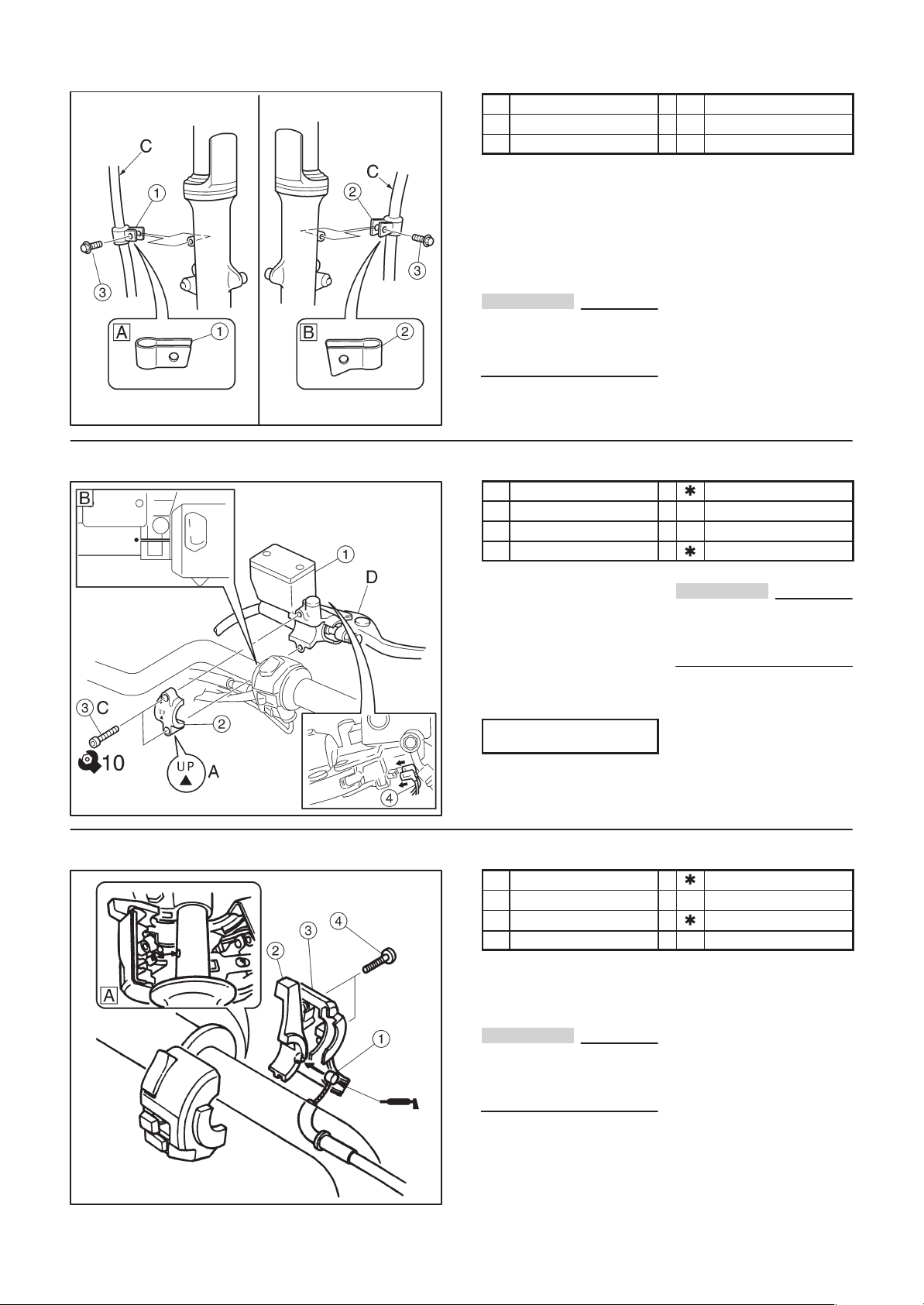
5. Front brake hose clamp
6. Front brake master cylinder
1 Brake hose clamp (right) 1 V
2 Brake hose clamp (left) 1 V
3 Flange bolt 2 V d = 6, = 25
A: Install the brake hose clamp on
the right side brake hose.
B: Install the brake hose clamp on
the left side brake hose.
C: Pass the brake hose through
the brake hose holder and secure the holder to the front fork.
CAUTION:
Proper hose routing is essential
to assure safe motorcycle operation.
Refer to “CABLE ROUTING”.
1
Master cylinder 1
2 Bracket 1 V
3 Hexagon socket bolt 2 V d = 6, = 10
4 Brake switch lead 2
7. Handlebar switch (left)
A: Make sure that the “UP” mark
with the bracket is pointed upward.
B: Align the punch mark on the
handlebar with the gap of the
master cylinder bracket.
C: Tighten the bolts in stages and
maintain an equal gap on each
side of the bracket.
Tightening torque:
10 Nm (1.0 mkg)
D: Check the brake lever for
smooth action.
1
Starter cable 1
2 Starter lever 1 V
3 handlebar switch (left) 1
4 Panhead screw 2 C d = 5, = 25
A: Align the projection on the han-
dlebar switch (left) with the hole
in the handlebar.
CAUTION:
Proper cable and hose routing is
essential to assure safe motorcycle operation. Refer to
“CABLE ROUTING”.
CAUTION:
Proper cable routing is essential
to assure safe motorcycle operation.
Refer to “CABLE ROUTING”.
–4–
Page 9

8. Clutch cable
9. Band
1 Clutch cable 1
2 Clutch switch coupler 1
A: Check the clutch lever for
smooth action.
CAUTION:
Proper cable routing is essential
to assure safe motorcycle operation.
Refer to “CABLE ROUTING”.
1 Band 2 V
A: Clamp the left handlebar switch
lead.
B: Clamp the right handlebar
switch lead.
10. Rear view mirror
NOTE:
Refer to “CABLE ROUTING”.
Rear view mirror
1
(left and right)
2 Cap nut 4 V d = 6
2 C
–5–
Page 10

11. Windscreen
12. Inner panel
1 Windscreen 1 C
2 Special nut 6 V d = 5
3 Screw 6 V d = 5, = 23
CAUTION:
The windscreen is made of an
acrylate resin. Take care so that
it is not scratched.
A: Tighten the screw to specified
torque.
Tightening torque:
0.4 Nm (0.04 mkg)
1 Inner panel (left and right) 2 C
2 Button head screw 4 V d = 5, = 13
3 Button head screw 2 V d = 6, = 16
4 Plastic washer 2 V d = 6
13. Side cover (left)
A: Tighten the screw to specified
torque.
Tightening torque
1.5 Nm (0.2 mkg)
B: Tighten the screw to specified
torque.
Tightening torque
4.5 Nm (0.5 mkg)
1 Side cover (left) 1 C
2 Button head screw 1 V d = 6, = 16
A: Tighten the screw to specified
torque.
Tightening torque:
3.8 Nm (0.4 mkg)
–6–
Page 11

14. Battery
1 Battery 1
2 Bolt 2 d = 6, = 10
3 Band 1
4 Seat 1
A: Installing the battery.
NOTE:
Refer to “ADJUSTMENTS AND
PREDELIVERY SERVICE”.
B: First, connect the positive lead
(Red color lead) to the positive
terminal.
C: Connect the negative lead
(Black color lead) to the negative terminal.
NOTE:
Refer to “CABLE ROUTING”.
–7–
Page 12

CABLE ROUTING
WARNING
Proper cable and lead routing is essential to insure
safe motorcycle operation.
1
Handlebar switch lead (right)
2
Throttle cable 1
3
Throttle cable 2
4
Clutch cable
5
Starter cable
6
Handlebar switch lead (left)
7
Main switch lead
8
Battery negative lead
9
Battery positive lead
10
Battery
A
Fasten the handlebar switch lead (right) and handlebar with a plastic band.
B
Route the handlebar switch lead (right) backward
the throttle cable and right side the brake hose guide.
C
Fasten the handlebar switch lead (left) and handlebar with a plastic band.
D
Route the throttle cable 1 and 2 backward the brake
hose, and left side the brake hose guide.
E
Fasten the battery negative lead with a battery band.
F
Insert the ground lead coupler in the battery band.
–8–
Page 13

ADJUSTMENTS AND PREDELIVERY SERVICE
–9–
Page 14

A. CHECKING AND CHARGING THE BAT-
TERY
NOTE:
The battery used in this motorcycls is a new version maintenance free “Valve Regulated Lead
Acid Battery”, it has been pre-filled with electrolyte
at the factory so there is no need for you to add any
fluid at any time.
1. Check:
Using a digital volt meter, the state of a discharged MF battery can be chacked by measuring open-circuit voltage (the voltage measured with the positive and negative terminals
being disconnected).
Open-circuit
voltage
12.8 V or
higher
Charging time
Charging is not necessary
WARNING
Do not attempt boost charging under any
circumstances.
Battery electrolyte is poisonous and danger-
ous, causing severe burns, etc. Contains
sulfric acid. Avoid contact with skin, eyes or
clothing.
Antidote: External – Flush with water. Internal – Drink large quantities of water or milk.
Follow with milk of magnesia, beaten egg, or
vegetable oil. Call physician immediately .
Eyes: Flush with water for 15 minutes and
get prompt medical attention. Batteries produce explosive gases. Keep sparks, flame,
cigarettes, etc., away . V entilate when charging or using in enclosed space. Always
shield eyes when working near batteries.
KEEP OUT OT REACH OF CHILDREN.
CAUTION:
If the voltage is lower than 12.8 V the battery
must be charged. If this is not done, the life
of the battery will be shortened drastically.
Since the procedure for charging the battery
is not explained in the assembly manual, refer to the service manual for more datails.
Never remove the strip of caps, nor add any
water or electrolyte.
B. DRAIN THE FUEL
1. Put a rag under the carburetor drain hose so
fuel does not contact the crankcase.
2. Loosen the four drain screws
standing fuel.
and drain the
1
WARNING
FUEL IS HIGHLY FLAMMBLE:
Always turn off the engine when draining.
Take care not to spill any fuel on the engine
or exhaust pipe(s)/muffler(s) when draining.
Never drain fuel while smoking or in the vi-
cinity of an open flame.
3. Retighten the four drain screws securely.
–10–
Page 15

EAA00128
C. CHECKING THE TIRE PRESSURE
1. Measure:
tire pressure
Out of specification Adjust.
WARNING
Tire inflation pressure should be checked
and adjusted when the temperature of the
tire equals the ambient air temperature. Tire
inflation pressure must be adjusted according to total weight of cargo, rider, and accessories (fairing, saddlebags, etc. if approved
for this model), and vehicle speed.
Proper loading of your motorcycle is impor-
tant for the handling, braking, and other performance and safety characteristics of your
motorcycle. Do not carry loosely packed
items that can shift.
Securely pack your heaviest items close to
the center of the motorcycle, and distribute
the weight evenly from side to side. Properly
adjust the suspension for your load, and
check the condition and pressure of your
tires.
NEVER OVERLOAD YOUR MOTORCYCLE.
Make sure the total weight of the cargo, rider,
and accessories (fairing, saddlebags, etc. if
approved for this model) does not exceed the
maximum load of the motorcycle. Operation of
an overload motorcycle could cause tire damage, an accident, or even injury.
Basic weight
with oil and a
231 kg
full fuel tank
Maximum
load*
Cold tire
pressure
Up to 90 kg
load*
90 kg
maximum load*
High
speed riding
(2.5 kgf/cm2)
(2.5 kgf/cm2)
(2.5 kgf/cm2)
189 kg
Front Rear
250 kPa
270 kPa
2.7 kgf/cm2)
250 kPa
290 kPa
(2.9 kgf/cm2)
250 kPa
290 kPa
(2.9 kgf/cm2)
*: total of cargo, rider, passenger and accessories
EAA00129
D. CHECKING THE ENGINE OIL LEVEL
1. Stand the motorcycle on a level surface.
NOTE:
Place the motorcycle on a suitable stand.
Make sure that the motorcycle is upright.
2. Let the engine idle for a few minutes.
3. Check:
engine oil level
The engine oil level should be between the
a
minimum level marks
marks
.
b
and maximum level
Below the minimum level mark Add the recommended engine oil to the proper level.
Recommended engine oil
Refer to the chart for the engine oil grade
which is best suited for certain atmospheric
temperatures.
API standard
SE or higher grade
ACEA standard
G4 or G5
Quantity
With oil filter element replacement
3.0 L
CAUTION:
Engine oil also lubricates the clutch and the
wrong oil types or additives could cause
clutch slippage. Therefore, do not add any
chemical additives or use engine oils with a
grade of CD
labeled “ENERGY CONSERVING II”
a
or higher and do not use oils
or
b
higher.
Do not allow foreign materials to enter the
crankcase.
4. Start the engine, warm it up for several minutes, and then turn it off.
5. Check the engine oil level again.
NOTE:
Before checking the engine oil level, wait a few
minutes until the oil has settled.
–11–
Page 16

EAA00136
E. CHECKING THE COOLANT LEVEL
1. Stand the motorcycle on a level surface.
NOTE:
Place the motorcycle on a suitable stand.
Make sure that the motorcycle is upright.
2. Check:
coolant level
The coolant level should be between the maximum level mark
.
b
a
and minimum level marks
Below the minimum level mark Add the recommended coolant to the proper level.
CAUTION:
Adding water instead of coolant lowers the
antifreeze content of the coolant. If water is
used instead of coolant, check and correct
the antifreeze concentration of the coolant.
Use only distilled water. Soft water may be
used if distilled water is not available.
3. Start the engine, warm it up for several minutes, and then turn it off.
4. Check:
coolant level
NOTE:
Before checking the coolant level, wait a few minutes until it settles.
EAA00140
F. ADJUSTING THE ENGINE IDLING SPEED
NOTE:
Prior to adjusting the engine idling speed, the carburetor synchronization should be adjusted properly, the air filter should be clean, and the engine
should have adequate compression.
1. Start the engine and let it warm up for several
minutes.
2. Attach:
engine tachometer
(to the spark plug lead of cylinder #1)
Engine tachometer
90890-031 13
3. Measure:
engine idling speed
Out of specification Adjust.
Engine idling speed
1,050 1,150 r/min
EAA00141
G. ADJUSTING THE THROTTLE CABLE FREE
PLA Y
NOTE:
Prior to adjusting the throttle cable free play, the
engine idling speed should be adjusted.
1. Measure:
throttle cable free play
a
Out of specification Adjust.
Throttle cable free play (at the
flange of the throttle grip)
3 5 mm
4. Adjust:
engine idling speed
a. Turn the pilot screw
in or out until it is lightly
1
seated.
b. Turn the pilot screw out the specified number of
turns.
Pilot screw
2 turns out
c. Turn the throttle stop screw
or
until the specified engine idling speed is
b
in direction
2
obtained.
Engine idling speed is
Direction
Direction
a
increased.
Engine idling speed is
b
decreased.
2. Adjust:
a. Loosen the locknut
b. Turn the adjusting nut 2 in direction
.
1
a
or
until the specified throttle cable free play is obtained.
Throttle cable free play is
Direction
Direction
a
increased.
Throttle cable free play is
b
decreased.
c. Tighten the locknut.
WARNING
After adjusting the throttle cable free play, turn
the handlebar to the right and to the left to ensure that this does not cause the engine idling
speed to change.
a
b
–12–
Page 17

EAA00142
H. ADJUSTING THE FRONT BRAKE
1. Adjust:
D brake lever position
(distance
lever)
a. While pushing the brake lever forward, turn the
adjusting dial
desired position.
NOTE:
Be sure to align the setting on the adjusting dial
with the arrow mark
Position #1 Distance is the largest.
Position #4 Distance is the smallest.
a
from the throttle grip to the brake
until the brake lever is in the
1
on the brake lever holder.
2
a
a
WARNING
After adjusting the brake lever position, make
sure that the pin on the brake lever holder is
firmly inserted in the hole in the adjusting dial.
CAUTION:
After adjusting the brake lever position, make
sure that there is no brake drag.
WARNING
A soft or spongy feeling in the brake lever can
indicate the presence of air in the brake system. Before the vehicle is operated, the air
must be removed by bleeding the brake system. Air in the brake system will considerably
reduce braking performance and could result
in loss of control and possibly an accident.
Therefore, check and, if necessary, bleed the
brake system.
EAA00146
I. ADJUSTING THE REAR BRAKE
1. Measure:
D brake pedal position
(distance
the top of the brake pedal)
Out of specification Adjust.
Brake pedal position (below the top of the
rider footrest)
40 mm
2. Adjust:
D brake pedal position
a. Loosen the locknut
b. Turn the adjusting bolt 2 in direction
until the specified brake pedal position is obtained.
Direction Brake pedal is raised.
Direction Brake pedal is lowered.
a
from the top of the rider footrest to
.
1
a
b
a
or
WARNING
After adjusting the brake pedal position, check
that the end of the adjusting bolt
through the hole
c
.
is visible
2
c. Tighten the locknut
Locknut
18 Nm (1.8 mSkg)
to specification.
1
WARNING
A soft or spongy feeling in the brake pedal can
indicate the presence of air in the brake system. Before the vehicle is operated, the air
must be removed by bleeding the brake system. Air in the brake system will considerably
reduce braking performance and could result
in loss of control and possibly an accident.
Therefore, check and, if necessary, bleed the
brake system.
b
CAUTION:
After adjusting the brake pedal position, make
sure that there is no brake drag.
–13–
Page 18

A
B
EAA00151
J. CHECKING THE BRAKE FLUID LEVEL
1. Stand the motorcycle on a level surface.
NOTE:
D Place the motorcycle on a suitable stand.
D Make sure that the motorcycle is upright.
2. Check:
D brake fluid level
Below the minimum level mark
a
Add the
recommended brake fluid to the proper level.
Recommended brake fluid
DOT 4
WARNING
D Use only the designated brake fluid. Other
brake fluids may cause the rubber seals to
deteriorate, causing leakage and poor brake
performance.
D Refill with the same type of brake fluid that is
already in the system. Mixing brake fluids
may result in a harmful chemical reaction,
leading to poor brake performance.
D When refilling, be careful that water does not
enter the reservoir. Water will significantly
lower the boiling point of the brake fluid and
could cause vapor lock.
Front brake
A
Rear brake
B
EAA00154
K. BLEEDING THE HYDRAULIC BRAKE SYS-
TEM
WARNING
Bleed the hydraulic brake system whenever:
D the system was disassembled,
D a brake hose was loosened or removed,
D the brake fluid level is very low,
D brake operation is faulty.
1. Remove:
D reservoir cap
D diaphragm
1
2
NOTE:
D Be careful not to spill any brake fluid or allow the
brake fluid reservoir to overflow.
D When bleeding the hydraulic brake system,
make sure that there is always enough brake
fluid before applying the brake. Ignoring this precaution could allow air to enter the hydraulic
brake system, considerably lengthening the
bleeding procedure.
D If bleeding is difficult, it may be necessary to let
the brake fluid settle for a few hours. Repeat the
bleeding procedure when the tiny bubbles in the
hose have disappeared.
2. Bleed:
D hydraulic brake system
CAUTION:
Brake fluid may damage painted surfaces and
plastic parts. Therefore, always clean up any
spilt brake fluid immediately.
NOTE:
In order to ensure a correct reading of the brake
fluid level, make sure that the top of the reservoir is
horizontal.
c. Connect a clear plastic hose
tightly to the
1
bleed screw 2.
Front
A
Rear
B
d. Place the other end of the hose into a contain-
er.
e. Slowly apply the brake several times.
f. Fully squeeze the brake lever or fully depress
the brake pedal and hold it in position.
g. Loosen the bleed screw.
This will release the tension and cause the
brake lever to contact the throttle grip or the
brake pedal to fully extend.
h. Tighten the bleed screw and then release the
brake lever or brake pedal.
i. Repeat steps (e) to (h) until all of the air
bubbles have disappeared from the brake fluid
in the plastic hose.
j. Tighten the bleed screw to specification.
Bleed screw
6 Nm (0.6 mSkg)
k. Fill the reservoir to the proper level.
Refer to “CHECKING THE BRAKE FLUID
LEVEL”.
WARNING
After bleeding the hydraulic brake system,
check the brake operation.
a. Add the recommended brake fluid to the prop-
er level.
b. Install the brake fluid resorvoir diaphragm.
–14–
Page 19

L. ADJUSTING THE CLUTCH CABLE FREE
PLAY
1. Check:
clutch cable free play
Out of specification Adjust.
Clutch cable free play (at the end of the clutch
lever)
10 15 mm
2. Adjust:
clutch cable free play
a
Clutch cable free play is
Direction
Direction
c. Tighten the locknut.
NOTE:
If the specified clutch cable free play cannot be obtained on the handlebar side of the cable, use the
adjusting nut on the engine side.
a
increased.
Clutch cable free play is
b
decreased
a. Loosen the locknut
b. Turn the adjusting bolt 2 in direction
until the specified clutch cable free play is obtained.
.
1
a
or
b
–15–
Page 20

EAA00159
M. ADJUSTING THE FRONT FORK LEGS
The following procedure applies to both of the front
fork legs.
WARNING
Always adjust both front fork legs evenly.
Uneven adjustment can result in poor handling and loss of stability.
Securely support the motorcycle so that
there is no danger of it falling over.
Rebound damping
CAUTION:
Never go beyond the maximum or minimum
adjustment positions.
1. Adjust:
rebound damping
a. Turn the adjusting screw
.
b
in direction
2
a
or
Spring preload
CAUTION:
Grooves are provided to indicate the adjust-
ment position.
Never go beyond the maximum or minimum
adjustment positions.
1. Adjust:
spring preload
a. Turn the adjusting bolt
Spring preload is
Direction
Direction
Adjusting positions
Standard: 4
Minimum: 8
Maximum: 1
increased (suspension is
a
harder).
Spring preload is
decreased (suspension is
b
softer).
in direction
1
a
or
b
Rebound damping is
Direction
Direction
Adjusting positions
Standard: 7 clicks out*
.
Minimum: 17 clicks out*
Maximum: 1 clicks out*
*: from the fully turned-in position
Compression damping
increased (suspension is
a
harder).
Rebound damping is
decreased (suspension is
b
softer).
CAUTION:
Never go beyond the maximum or minimum
adjustment positions.
1. Adjust:
compression damping
a. Turn the adjusting screw
.
b
Compression damping is
Direction
Direction
increased (suspension is
a
harder).
Compression damping is
decreased (suspension is
b
softer).
in direction
3
a
or
–16–
Adjusting positions
Standard: 6 clicks out*
Minimum: 21 clicks out*
Maximum: 1 clicks out*
*: from the fully turned-in position
Page 21

EAA00169
N. ADJUSTING THE REAR SHOCK ABSORB-
ER ASSEMBL Y
WARNING
Securely support the motorcycle so that there
is no danger of it falling over.
Spring preload
CAUTION:
Never go beyond the maximum or minimum
adjustment positions.
1. Adjust:
spring preload
NOTE:
Adjust the spring preload with the special wrench
and extension bar included in the owner’s tool kit.
a. Turn the adjusting ring
b. Align the desired position on the adjusting ring
with the stopper
Direction
Direction
a
b
in direction
1
.
2
Spring preload is
increased (suspension
is harder).
Spring preload is
decreased (suspension
is softer).
a
or
b
Rebound damping
CAUTION:
Never go beyond the maximum or minimum
adjustment positions.
1. Adjust:
rebound damping
a. Turn the adjusting knob
.
b
Direction
Direction
Adjusting positions
.
Standard: 20 clicks out*
Minimum: 10 clicks out*
Maximum: 3 clicks out*
*: from the fully turned-in position
Compression damping
a
b
Rebound damping is
increased (suspension
is harder).
Rebound damping is
decreased (suspension
is softer).
in direction
2
CAUTION:
Never go beyond the maximum or minimum
adjustment positions.
a
or
Adjusting positions
Standard: 6
Minimum: 1
Maximum: 11
1. Adjust:
compression damping
a. Turn the adjusting screw
.
b
Compression damping is
a
Direction
Direction
Adjusting positions
Standard: 7 clicks in*
Minimum: 1 clicks in*
Maximum: 12 clicks in*
*: from the fully turned-out position
increased (suspension
is harder).
Compression damping is
decreased (suspension
b
is softer).
in direction
3
a
or
–17–
Page 22

EAA00178
O. ADJUSTING THE DRIVE CHAIN SLACK
NOTE:
The drive chain slack must be checked at the tightest point on the chain.
CAUTION:
A drive chain that is too tight will overload the
engine and other vital parts, and one that is too
loose can skip and damage the swingarm or
cause an accident. Therefore, keep the drive
chain slack within the specified limits.
1. Stand the motorcycle on a level surface.
WARNING
Securely support the motorcycle so that there
is no danger of it falling over.
4. Loosen:
D wheel axle nut
1
5. Adjust:
D drive chain slack
a. Loosen both locknuts 2.
b. Turn both adjusting bolts 3 in direction
until the specified drive chain slack is ob-
b
a
or
tained.
Direction Drive chain is tightened.
Direction Drive chain is loosened.
a
b
NOTE:
D To maintain the proper wheel alignment, adjust
both sides evenly.
D Push the rear wheel forward to make sure that
there is no clearance between the wheel axle
plates and the end of the adjusting bolts.
NOTE:
Both wheels should be on the ground without a rider on the motorcycle.
2. Rotate the rear wheel several times and check
the drive chain to locate its tightest point.
3. Measure:
D drive chain slack
a
Out of specification Adjust.
Drive chain slack
40 50 mm
EAA00181
P. ADJUSTING THE REAR BRAKE LIGHT
SWITCH
NOTE:
The rear brake light switch is operated by movement of the brake pedal.
The rear brake light switch is properly adjusted
when the brake light comes on just before the braking effect starts.
1. Check:
D rear brake light operation timing
Incorrect Adjust.
c. Tighten the wheel axle nut to specification.
Wheel axle nut
150 Nm (15 mSkg)
d. Tighten the locknuts to specification.
Locknut
16 Nm (1.6 mSkg)
2. Adjust:
D rear brake light operation timing
a. Hold the main body
of the rear brake light
1
switch so that it does not rotate and turn the ad-
a
justing nut
in direction
2
or
b
until the rear
brake light comes on at the proper time.
Direction
Direction
a
b
Brake light comes on
sooner.
Brake light comes on
later.
EAA00184
Q. ADJUSTING THE HEADLIGHT BEAMS
The following procedure applies to both of the
headlights.
1. Adjust:
D headlight beam (vertically)
a. Turn the adjusting screw
.
b
Direction Headlight beam is raised.
Direction Headlight beam is lowered.
a
b
in direction
1
a
or
–18–
2. Adjust:
D headlight beam (horizontally)
a. Turn the adjusting knob
.
b
2
Left headlight
Direction
Direction
a
b
Headlight beam moves to
the right.
Headlight beam moves to
the left.
Right headlight
Direction
Direction
a
b
Headlight beam moves to
the left.
Headlight beam moves to
the right.
in direction
a
or
Page 23

EAA00185
R. ADJUSTING THE DIGITAL CLOCK
NOTE:
This digital clock constantly displays the time.
1. Adjust:
digital clock
a. Hold down the “RESET” button 2 and “SE-
LECT” button
b. Push the “RESET” button 2 to set the hour.
And push the “SELECT” button.
c. Push the “RESET” button 2 to set the min-
utes. And push the “SELECT” button.
NOTE:
When setting the time (e.g., after reconnecting the
battery), first set the clock to 1:00 AM, then set it to
the correct time.
1
.
3
–19–
Page 24

APPENDICES
SERVICE DAT A
FZS1000 (N) 2001
Engine idling speed: 1,050 1,150 r/min
Spark plug:
Type
Gap
Fuel:
Recommended fuel
Fuel tank capacity Total:
Valve clearance (cold): IN
EX
Maximum load * 201 kg
Up to 90 kg load *
Tire pressure
90 kg Maximum load *
High speed riding
CR9E (NGK), U27ESR-N (DENSO)
0.7 0.8 mm
Regular unleaded gasoline
21 L
0.11 0.20 mm
0.21 0.25 mm
Front Rear
250 kPa
(2.5 kgf/cm
2
, 2.5 bar)
250 kPa
(2.5 kgf/cm2, 2.5 bar)
250 kPa
(2.5 kgf/cm2, 2.5 bar)
270 kPa
(2.7 kgf/cm
2
, 2.7 bar)
290 kPa
(2.9 kgf/cm2, 2.9 bar)
290 kPa
(2.9 kgf/cm2, 2.9 bar)
* Load is the total weight of cargo, rider, passenger, and accessories.
ST ANDARD EQUIPMENT
No.
Part name Q’ty
1 Owner’s manual 1
2 Owner’s tool kit 1
OWNER’S TOOL KIT
No. Part name Q’ty
1 Owner’s tool bag 1
2 Pliers 1
3 Wrench (10 – 12) 1
4 Wrench (12 – 14) 1
5 Wrench (14 – 17) 1
6 Wrench (32) 1
7 Special wrench 1
8 Extension bar 1
9 Spark plug wrench 1
10 Screwdriver grip 1
11 Screwdriver bit (phillips-slotted) 1
12 Screwdriver bit (phillips) 1
13 Hexagon wrench (3) 1
14 Hexagon wrench (4) 1
15 Hexagon wrench (5) 1
–20–
Page 25

TIGHTENING TORQUE
Part to be tightened
Thread size
Engine:
Spark plug
Engine oil drain bolt
Chassis
Upper bracket pinch bolt
Upper bracket cap nut
Upper bracket and handlebar holder
Handlebar holder
Lower bracket pinch bolt
Lower bracket ring nut
Front brake master cylinder
Front brake hose union bolt
Engine mounting
Engine mounting bolt/nut
Engine mounting bolt/nut
Frame and down tube
Clutch cable lock nut
Ignition coil and stay
Pivot shaft
Rear shock absorber (upper)
Rear shock absorber and relay arm
Relay arm and frame
Relay arm and connecting arm
Connecting arm and swing arm
Drive chain guard
Drive chain case
Fuel cock
Fuel sender
Side cover
Coolant reservoir tank
Front wheel axle
Front wheel axle pinch bolt
Front brake caliper
Front brake disk
Front brake bleed screw
Rear brake torque rod
Rear wheel sprocket
Drive chain adjusting nut
Rear brake caliper
Rear wheel axle
Rear brake hose union bolt
Rear brake bleed screw
Rear brake disk
Rider footrest bracket and frame
Rear brake reservoir tank
Rear brake master cylinder
Rider footrest and bracket
Passenger footrest bracket and frame
Passenger footrest bracket and muffler
M10
M14
M8
M22
M10
M8
–
M25
M6
M10
M10
M8
M10
M8
M6
M18
M10
M10
M10
M12
M12
M6
M6
M6
M5
M6
M6
M16
M8
M10
M6
M8
M8
M10
M8
M10
M24
M10
M8
M8
M8
M6
M8
M10
M8
M10
Tightening torque
Nm mkg
13
43
30
110
32
23
23
See note
10
30
55
33
89
7
7
125
40
40
40
48
48
7
7
7
4
4
4
72
23
40
18
6
23
69
16
40
150
30
6
23
30
4
23
55
28
48
1.3
4.3
3.0
11
3.2
2.3
2.3
10
3.0
5.5
3.3
8.9
0.7
0.7
12.5
4.0
4.0
4.0
4.8
4.8
0.7
0.7
0.7
0.4
0.4
0.4
7.2
2.3
4.0
1.8
0.6
2.3
6.9
1.6
4.0
15
3.0
0.6
2.3
3.0
0.4
2.3
5.5
2.8
4.8
NOTE:
1. First, tighten the ring nut approximately 52 Nm (5.2 mkg) by using the torque wrench, then loosen the ring nut
2. Retighten the ring nut 18 Nm (1.8 mkg).
completely .
–21–
Page 26

HOW TO USE THE CONVERSION TABLE
Torque
Weight
Distance
Mi
neous
All specification date in this manual is listed
in SI and METRIC UNITS.
Use this table to convert METRIC unit data
to IMP unit data.
Ex.
METRIC MULTIPLIER IMP
**mm 0.03937 = **in
2 mm 0.03937 = 0.08in
Volume/
Capacity
scella-
CONVERSION TABLE
METRIC TO IMP
Known Multiplier Result
mSkg 7.233 ftSlb
mSkg 86.794 inSlb
cmSkg 0.0723 ftSlb
cmSkg 0.8679 inSlb
kg 2.205 lb
g 0.03527 oz
km/hr 0.6214 mph
km 0.6214 mi
m 3.281 ft
m 1.094 yd
cm 0.3937 in
mm 0.03937 in
cc (cm3) 0.03527 oz (IMP liq.)
cc (cm3) 0.06102 cu. in
lit (liter) 0.8799 qt (IMP liq.)
lit (liter) 0.2199 gal (IMP liq.)
kg/mm 55.997 lb/in
2
kg/cm
Centigrade 9/5 (_C) +32 Fahrenheit (_F)
14.2234 psi (lb/in2)
–22–
Page 27

Page 28

PRINTED ON RECYCLED PAPER
PRINTED IN BELGIUM
2000 12 - 1.4 1
I
 Loading...