

Yamaha F15HP, F20HP User Manual

OWNER’S MANUAL
F15C
F20
U.S.A.Edition
LIT-18626-07-17
6AG-28199-10
EMU25060
Read this owner’s manual carefully before operating your outboard motor.
ZMU01690
Important manual information
EMU31280
To the owner
Thank you for choosing a Yamaha outboard
motor. This Owner’s Manual contains information needed for proper operation, maintenance and care. A thorough understanding
of these simple instructions will help you obtain maximum enjoyment from your new
Yamaha. If you have any question about the
operation or maintenance of your outboard
motor, please consult a Yamaha dealer.
In this Owner’s Manual particularly important
information is distinguished in the following
ways.
The Safety Alert Symbol means
ATTENTION! BECOME ALERT! YOUR
SAFETY IS INVOLVED!
EWM00780
WARNING
Failure to follow WARNING instructions
could result in severe injury or death
the machine operator, a bystander, or a
person inspecting or repairing the outboard motor.
ECM00700
CAUTION:
A CAUTION indicates special precautions
that must be taken to avoid damage to the
outboard motor.
to
al, please consult your Yamaha dealer.
NOTE:
The F15CEH, F15CMH, F15CPH, F20EH,
F20ER, F20MH, F20PH, F20PR and the
standard accessories are used as a base for
the explanations and illustrations in this
manual. Therefore some items may not apply to every model.
EMU25110
F15C, F20
OWNER’S MANUAL
©2006 by Yamaha Motor Corporation, USA
1st edition, June 2006
All rights reserved.
Any reprinting or unauthorized use
without the written permission of
Yamaha Motor Corporation, USA
is expressly prohibited.
Printed in Japan
P/N LIT-18626-07-17
NOTE:
A NOTE provides key information to make
procedures easier or clearer.
Yamaha continually seeks advancements in
product design and quality. Therefore, while
this manual contains the most current product information available at the time of printing, there may be minor discrepancies
between your machine and this manual. If
there is any question concerning this manu-

Table of contents
General information .......................... 1
Identification numbers record.......... 1
Outboard motor serial number .......... 1
Key number....................................... 1
Emission control information ........... 1
North American models..................... 1
Star labels ......................................... 2
Safety information ........................... 3
Important labels............................... 4
Warning labels ..................................4
Caution labels ...................................5
Basic boating rules (Rules of the
road) .............................................. 5
Steering and sailing rules and
sound signals.................................. 6
Rules when encountering vessels .... 6
Other special situations..................... 7
Fueling instructions ......................... 9
Gasoline.......................................... 10
Engine oil ........................................10
Battery requirement....................... 11
Battery specifications ...................... 11
Without a rectifier or Rectifier
Regulator ...................................... 11
Propeller selection......................... 12
Start-in-gear protection ................. 12
Basic components ..........................13
Main components.......................... 13
Fuel tank .........................................13
Fuel joint ......................................... 14
Fuel gauge ...................................... 14
Fuel tank cap .................................. 14
Air vent screw ................................. 14
Remote control................................ 14
Remote control lever....................... 14
Neutral interlock trigger................... 15
Neutral throttle lever........................ 15
Tiller handle .................................... 15
Gear shift lever................................ 15
Throttle grip..................................... 16
Throttle indicator .............................16
Throttle friction adjuster................... 16
Engine stop lanyard switch .............17
Engine stop button .......................... 17
Manual starter handle .....................18
Starter button ..................................18
Main switch .....................................18
Power tilt switch ..............................18
Steering friction adjuster .................19
Steering friction adjuster .................20
Trim tab ...........................................20
Trim rod (tilt pin) ..............................20
Tilt lock mechanism......................... 21
Tilt support knob.............................. 21
Tilt support bar ................................21
Power tilt unit................................... 21
Top cowling lock lever (pull up
type) .............................................. 22
Flushing device ...............................22
Warning indicator ............................22
Warning system ............................ 22
Overheat warning............................ 22
Low oil pressure warning ................23
Operation ......................................... 25
Installation..................................... 25
Mounting the outboard motor ..........25
Clamping the outboard motor.......... 27
Breaking in engine ........................ 28
Procedure for 4-stroke models........ 28
Preoperation checks ..................... 28
Fuel .................................................28
Controls........................................... 28
Engine .............................................28
Checking the engine oil level ..........29
Filling fuel...................................... 29
Ring Free Fuel Additive................... 29
Operating engine .......................... 30
Feeding fuel (portable tank) ............30
Starting engine ................................31
Warming up engine....................... 34
Manual start and electric start
models ..........................................34
Shifting.......................................... 35
Forward (tiller handle and remote
control models) .............................35
Reverse (automatic reverse lock
and power trim and tilt models)..... 36
Reverse (manual tilt and hydro tilt
models) ......................................... 36
Stopping engine............................ 37

Table of contents
Procedure ....................................... 37
Trimming outboard motor.............. 38
Adjusting trim angle for manual tilt
models .......................................... 38
Adjusting trim angle (power tilt
models) ......................................... 39
Adjusting boat trim ..........................40
Tilting up and down ....................... 41
Procedure for tilting up (manual tilt
models) ......................................... 41
Procedure for tilting up (power trim
and tilt models / power tilt
models) ......................................... 42
Procedure for tilting down (manual
tilt models) .................................... 43
Procedure for tilting down (power
trim and tilt models / power tilt
models) ......................................... 44
Cruising in shallow water .............. 45
Cruising in shallow water (manual
tilt models) .................................... 45
Power trim and tilt models / power
tilt models...................................... 46
Cruising in other conditions........... 47
Maintenance..................................... 48
Specifications ................................ 48
Transporting and storing outboard
motor ........................................... 50
Dismounting the outboard motor..... 50
Storing outboard motor ...................52
Procedure ....................................... 52
Lubrication ...................................... 53
Cleaning and anticorrosion
measures ...................................... 53
Battery care..................................... 53
Flushing power unit......................... 54
Cleaning the outboard motor .......... 55
Checking painted surface of
motor............................................. 55
Periodic maintenance.................... 55
Replacement parts.......................... 56
Maintenance chart .......................... 57
Maintenance chart (additional)........ 58
Greasing ......................................... 59
Cleaning and adjusting spark
plug ............................................... 60
Checking fuel system ......................61
Inspecting fuel filter .........................62
Cleaning fuel filter ...........................62
Inspecting idling speed.................... 63
Changing engine oil ........................63
Checking wiring and connectors .....65
Exhaust leakage.............................. 65
Water leakage .................................66
Engine oil leakage........................... 66
Checking power trim and tilt /
power tilt system ........................... 66
Checking propeller ..........................66
Removing the propeller ...................67
Installing the Propeller..................... 67
Changing gear oil ............................68
Cleaning fuel tank ...........................69
Inspecting and replacing
anode(s)........................................ 69
Checking battery (for electric start
models) ......................................... 70
Connecting the battery ....................71
Disconnecting the battery................ 71
Checking top cowling ......................72
Coating the boat bottom.................. 72
Trouble Recovery............................ 73
Troubleshooting ............................ 73
Temporary action in emergency ... 76
Impact damage ...............................76
Replacing fuse ................................76
Power trim and tilt / power tilt will
not operate.................................... 77
Starter will not operate ....................77
Emergency starting engine
(manual starter model).................. 78
Emergency starting engine
(electric start model) .....................79
Treatment of submerged motor .... 82
Procedure........................................ 82
Consumer information ................... 83
Important warranty information for
U.S.A. and Canada ..................... 83
YAMAHA MOTOR
CORPORATION, U.S.A.
FOUR-STROKE OUTBOARD

Table of contents
MOTOR
THREE-YEAR LIMITED
WARRANTY ................................ 85
IMPORTANT WARRANTY
INFORMATION IF YOU USE
YOUR YAMAHA OUTSIDE THE
USA OR CANADA ......................87
EMU25170
Identification numbers record
EMU25183
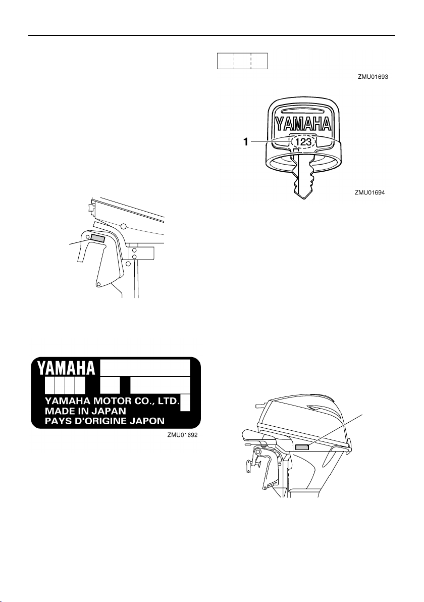
Outboard motor serial number
The outboard motor serial number is
stamped on the label attached to the port
side of the clamp bracket.
Record your outboard motor serial number in
the spaces provided to assist you in ordering
spare parts from your Yamaha dealer or for
reference in case your outboard motor is stolen.
1
ZMU05335
1. Outboard motor serial number location
General information
1. Key number
EMU25221
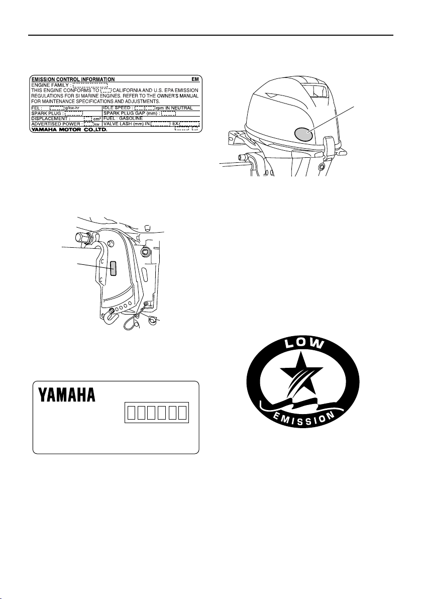
Emission control information
EMU25230
North American models
This engine conforms to U.S. Environmental
Protection Agency (EPA) regulations for marine SI engines. See the label affixed to your
engine for details.
EMU25242
Approval label of emission control certificate
This label is attached to the bottom cowling.
New Technology; (4-stroke/HPDI) EM
EMU25190
Key number
If a main key switch is equipped with the motor, the key identification number is stamped
on your key as shown in the illustration.
Record this number in the space provided for
reference in case you need a new key.
1
ZMU05516
1. Approval label location
1
General information
ZMU05159
EMU25262
Manufactured date label
This label is attached to the clamp bracket or
the swivel bracket.
1
ZMU05498
particular label.
1
ZMU05623
1. Star labels location
EMU25280
One Star—Low Emission
The one-star label identifies engines that
meet the Air Resources Board’s 2001 exhaust emission standards. Engines meeting
these standards have 75% lower emissions
than conventional carbureted two-stroke engines. These engines are equivalent to the
U.S. EPA’s 2006 standards for marine engines.
1. Manufactured date label location
Manufactured:
ZMU04346
EMU25272
Star labels
Your outboard motor is labeled with a California Air Resources Board (CARB) star label. See below for a description of your
2
ZMU01702
EMU25290
Two Stars—Very Low Emission
The two-star label identifies engines that
meet the Air Resources Board’s 2004 exhaust emission standards. Engines meeting
these standards have 20% lower emissions
than One Star-Low-Emission engines.
ZMU01703
EMU25300
Three Stars—Ultra Low Emission
The three-star label identifies engines that
meet the Air Resources Board’s 2008 exhaust emission standards. Engines meeting
these standards have 65% lower emissions
than One Star-Low-Emission engines.
ZMU01704
EMU25362
Safety information
●
Before mounting or operating the outboard
motor, read this entire manual. Reading it
should give you an understanding of the
motor and its operation.
Before operating the boat, read any own-
●
er’s or operator’s manuals supplied with it
and all labels. Be sure you understand
each item before operating.
Do not overpower the boat with this out-
●
board motor. Overpowering the boat could
result in loss of control. The rated power of
General information
the outboard should be equal to or less
than the rated horsepower capacity of the
boat. If the rated horsepower capacity of
the boat is unknown, consult the dealer or
boat manufacturer.
Do not modify the outboard. Modifications
●
could make the motor unfit or unsafe to
use.
Incorrect propeller selection and incorrect
●
use may not only cause engine damage,
but also adversely affect fuel consumption.
Consult your dealer for correct use.
●
Never operate after drinking alcohol or taking drugs. About 50% of all boating fatalities involve intoxication.
●
Have an approved personal flotation device (PFD) on board for every occupant. It
is a good idea to wear a PFD whenever
boating. At a minimum, children and nonswimmers should always wear PFDs, and
everyone should wear PFDs when there
are potentially hazardous boating conditions.
Gasoline is highly flammable, and its va-
●
pors are flammable and explosive. Handle
and store gasoline carefully. Make sure
there are no gas fumes or leaking fuel before starting the engine.
●
This product emits exhaust gases which
contain carbon monoxide, a colorless,
odorless gas which may cause brain damage or death when inhaled. Symptoms include nausea, dizziness, and drowsiness.
Keep cockpit and cabin areas well ventilated. Avoid blocking exhaust outlets.
Check throttle, shift, and steering for prop-
●
er operation before starting the engine.
●
Attach the engine stop switch lanyard cord
to a secure place on your clothing, or your
arm or leg while operating. If you accidentally leave the helm, the cord will pull from
3
General information
the switch, stopping the engine.
●
Know the marine laws and regulations
where you will be boating—and obey
them. For basic boating rules, see “Rules
of the road” on page 5.
Stay informed about the weather. Check
●
weather forecasts before boating. Avoid
boating in hazardous weather.
Tell someone where you are going: leave
●
a Float Plan with a responsible person. Be
sure to cancel the Float Plan when you return.
●
Use common sense and good judgment
when boating. Know your abilities, and be
sure you understand how your boat handles under the different boating conditions
you may encounter. Operate within your
limits, and the limits of your boat. Always
operate at safe speeds, and keep a careful
watch for obstacles and other traffic.
Always watch carefully for swimmers dur-
●
ing the engine operation.
●
Stay away from swimming areas.
When a swimmer is in the water near you
●
shift into neutral and shut off the engine.
●
Do not illegally discard empty containers
used to replace or replenish oil. For the
correct processing of empty containers,
consult the dealer where you purchased
the oil.
●
When replacing oils used to lubricate the
product (engine or gear oil), be sure to
wipe away any spilt oil. Never pour oil without using a funnel or similar device. If necessary, verify the necessary replacement
procedure with the dealer.
●
Never illegally discard (dump) the product.
Yamaha recommends consulting the deal-
er on discarding the product.
Be informed about boating safety. Additional
publications and information can be obtained
from many organizations, including the following:
United States Coast Guard
Consumer Affairs Staff (G-BC)
Office of Boating, Public, and Consumer Affairs
U.S. Coast Guard Headquarters
Washington, D.C. 20593-0001
Boating Safety Hotline: 1-800-368-5647
National Marine Manufacturers Association (NMMA)
401 N. Michigan Ave.
Chicago, Il 60611
Marine Retailers Association of America
155 N. Michigan Ave.
Chicago, Il 60601
EMU25382
Important labels
EMU25395
Warning labels
ZMU05514
EMU25401
Label
EWM01260
WARNING
●
Be sure shift control is in neutral before
starting engine. (except 2HP)
●
Do not touch or remove electrical parts
when starting or during operation.
●
Keep hands, hair, and clothes away
from flywheel and other rotating parts
while engine is running.
4
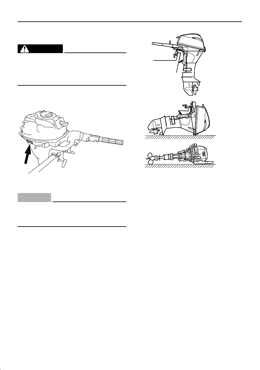
EMU25431
Label
EWM01300
WARNING
This engine is equipped with a neutral
●
starting device.
●
The engine will not start unless the shift
control is in neutral position.
EMU25465
Caution labels
General information
ZMU05515
EMU25473
Label
ECM01191
CAUTION:
Transport and store the engine only as
shown. Otherwise, engine damage could
result from leaking oil.
ZMU05630
EMU25500
Basic boating rules (Rules of
the road)
Just as there are rules which apply when you
are driving on streets and high ways, there
are waterway rules which apply when you
are driving your boat. These rules are used
internationally, and are also enforced by the
United States Coast Guard and local agencies. You should be aware of these rules,
and follow them whenever you encounter
another vessel on the water.
Several sets of rules prevail according to
geographic location, but are all basically the
same as the International Rules of the Road.
The rules presented here in your Owner’s
Manual are condensed, and have been provided for your convenience only. Consult
your local U.S. Coast Guard Auxiliary or Department of Motor Vehicles for a complete
set of rules governing the waters in which
5
General information
you will be using your boat.
EMU25510
Steering and sailing rules and sound signals
Whenever two vessels on the water meet
one another, one vessel has the right-ofway; it is called the “stand-on” vessel. The
vessel which does not have the right-of-way
is called the “give-way” or “burdened” vessel.
These rules determine which vessel has the
right-of-way, and what each vessel should
do.
Stand-on vessel
The vessel with the right-of-way has the duty
to continue its course and speed, except to
avoid an immediate collision. When you
maintain your direction and speed, the other
vessel will be able to determine how best to
avoid you.
Give-way vessel
The vessel which does not have the right-ofway has the duty to take positive and timely
action to stay out of the way of the Stand-On
vessel. Normally, you should not cross in
front of the vessel with the right-of-way. You
should slow down or change directions briefly and pass behind the other vessel. You
should always move in such a way that the
operator of the other vessel can see what
you are doing.
“The general prudential rule”
This rule is called Rule 2 in the International
Rules and says,
“In obeying and construing these rules due
regard shall be had to all dangers of navigation and collision, and to any special circumstances, which may render a departure from
the above rules necessary in order to avoid
immediate danger.”
In other words, follow the standard rules except when a collision will occur unless both
vessels try to avoid each other. If that is the
case, both vessels become “Give-Way” vessels.
EMU25520
Rules when encountering vessels
There are three main situations which you
may encounter with other vessels which
could lead to a collision unless the Steering
Rules are followed:
Meeting:
sel head-on)
Crossing:
er vessel’s path)
Overtaking:
passed by another vessel)
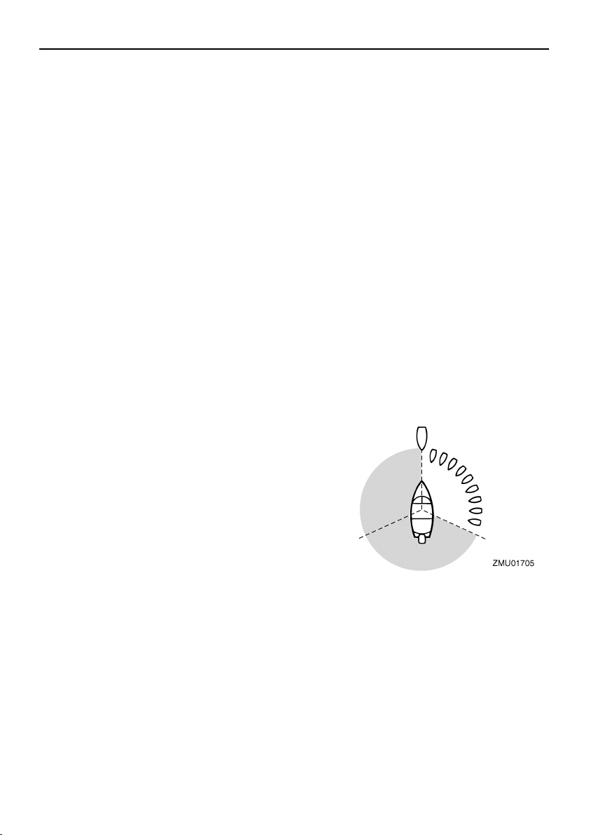
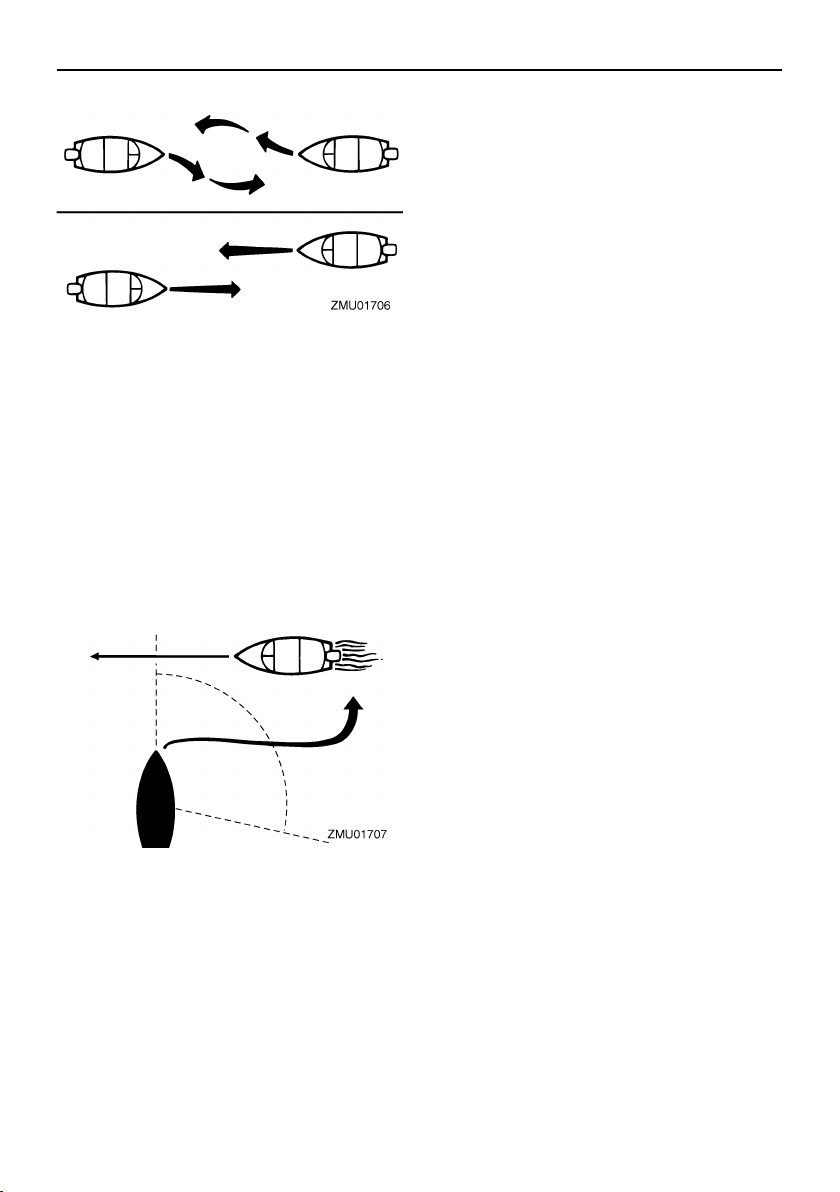
In the following illustration, your boat is in the
center. You should give the right-of-way to
any vessels shown in white area (you are the
Give-Way vessel). Any vessels in the shaded area must yield to you (they are the GiveWay vessels). Both you and the meeting
vessel must alter course to avoid each other.
Meeting
If you are meeting another power vessel
head on, and are close enough to run the risk
of collision, neither of you has the right-ofway! Both of you should alter course to avoid
an accident. You should keep the other vessel on your port (left) side. This rule doesn’t
apply if both of you will clear one another if
you continue on your set course and speed.
(you are approaching another ves-
(you are traveling across the oth-
(you are passing or being
6
Crossing
When two power driven vessels are crossing
each other’s path close enough to run the
risk of collision, the vessel which has the other on the starboard (right) side must keep out
of the way of the other. If the other vessel is
on your right, you must keep out of its way;
you are the Give-Way vessel. If the other
vessel is on your port (left) side, remember
that you should maintain course and direction, provided the other vessel gives you the
right-of-way as it should.
Overtaking
If you are passing another vessel, you are
the “Give-Way” vessel. This means that the
other vessel is expected to maintain its
course and speed. You must stay out of its
way until you are clear of it. Likewise, if another vessel is passing you, you should
maintain your speed and direction so that the
other vessel can steer itself around you.
General information
EMU25530
Other special situations
There are three other rules you should be
aware of when driving your boat around other vessels.
Narrow channels and bends
When navigating in narrow channels, you
should keep to the right when it is safe and
practical to do so. If the operator of a powerdriven vessel is preparing to go around a
bend that may obstruct the view of other water vessels, the operator should sound a prolonged blast on the whistle (4 to 6 seconds).
If another vessel is around the bend, it too
should sound the whistle. Even if no reply is
heard, however, the vessel should still proceed around the bend with caution. If you
navigate such waters with your boat, you will
need to carry a portable air horn, available
from local marine supply stores.
Fishing vessel right-of-way
All vessels which are fishing with nets, lines
or trawls are considered to be “fishing vessels” under the International Rules. Vessels
with trolling lines are not considered fishing
vessels. Fishing vessels have the right-ofway regardless of position. Fishing vessels
cannot, however, impede the passage of
other vessels in narrow channels.
Sailing vessel right-of-way
Sailing vessels should normally be given the
right-of-way. The exceptions to this are:
1. When the sailing vessel is overtaking
the power-driven vessel, the power-driven vessel has the right-of-way.
2. Sailing vessels should keep clear of any
fishing vessel.
3. In a narrow channel, a sailing vessel
should not hamper the safe passage of
a power-driven vessel which can navigate only in such a channel.
7

General information
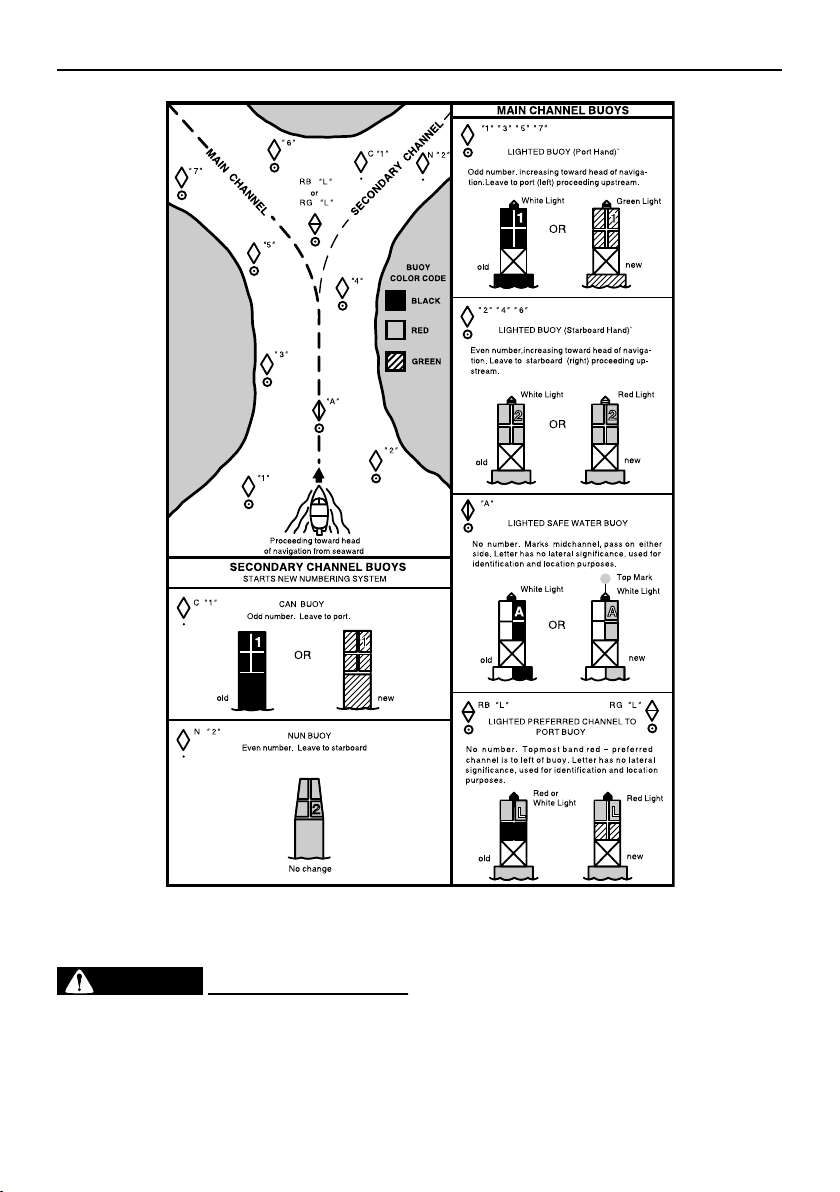
Reading buoys and other markers
The waters of the United states are marked
for safe navigation by the lateral system of
buoyage. Simply put, buoys and markers
have an arrangement of shapes, colors,
numbers and lights to show which side of the
buoy a boater should pass on when navigating in a particular direction. The markings on
these buoys are oriented from the perspective of being entered from seaward (the boater is going towards the port). This means that
red buoys are passed on the starboard
(right) side when proceeding from open water into port, and black buoys are to port (left)
side. When navigating out of port, your position with respect to the buoys should be reversed; red buoys should be to port and
black buoys to starboard.
Many bodies of water used by boaters are
entirely within the boundaries of a particular
state. The Uniform State Waterway Marking
System has been devised for these waters.
This system uses buoys and signs with distinctive shapes and colors to show regulatory or advisory information. These markers
are white with black letters and orange
boarders. They signify speed zones, restricted areas, danger areas, and general information.
Remember, markings may vary by geographic location. Always consult local boating authorities before driving your boat in
unfamiliar waters.
8
General information
EMU25540
Fueling instructions
EWM00010
WARNING
GASOLINE AND ITS VAPORS ARE HIGHLY FLAMMABLE AND EXPLOSIVE!
●
Do not smoke when refueling, and keep
ZMU01708
away from sparks, flames, or other
sources of ignition.
●
Stop engine before refueling.
●
Refuel in a well-ventilated area. Refuel
portable fuel tanks off the boat.
●
Take care not to spill gasoline. If gasoline spills, wipe it up immediately with
9
General information
dry rags.
●
Do not overfill the fuel tank.
Tighten the filler cap securely after re-
●
fueling.
●
If you should swallow some gasoline,
inhale a lot of gasoline vapor, or get
gasoline in your eyes, get immediate
medical attention.
If any gasoline spills onto your skin, im-
●
mediately wash with soap and water.
Change clothing if gasoline spills on it.
Touch the fuel nozzle to the filler open-
●
ing or funnel to help prevent electrostatic sparks.
ECM00010
CAUTION:
Use only new clean gasoline which has
been stored in clean containers and is not
contaminated with water or foreign matter.
EMU25570
Gasoline
If knocking or pinging occurs, use a different
brand of gasoline or premium unleaded fuel.
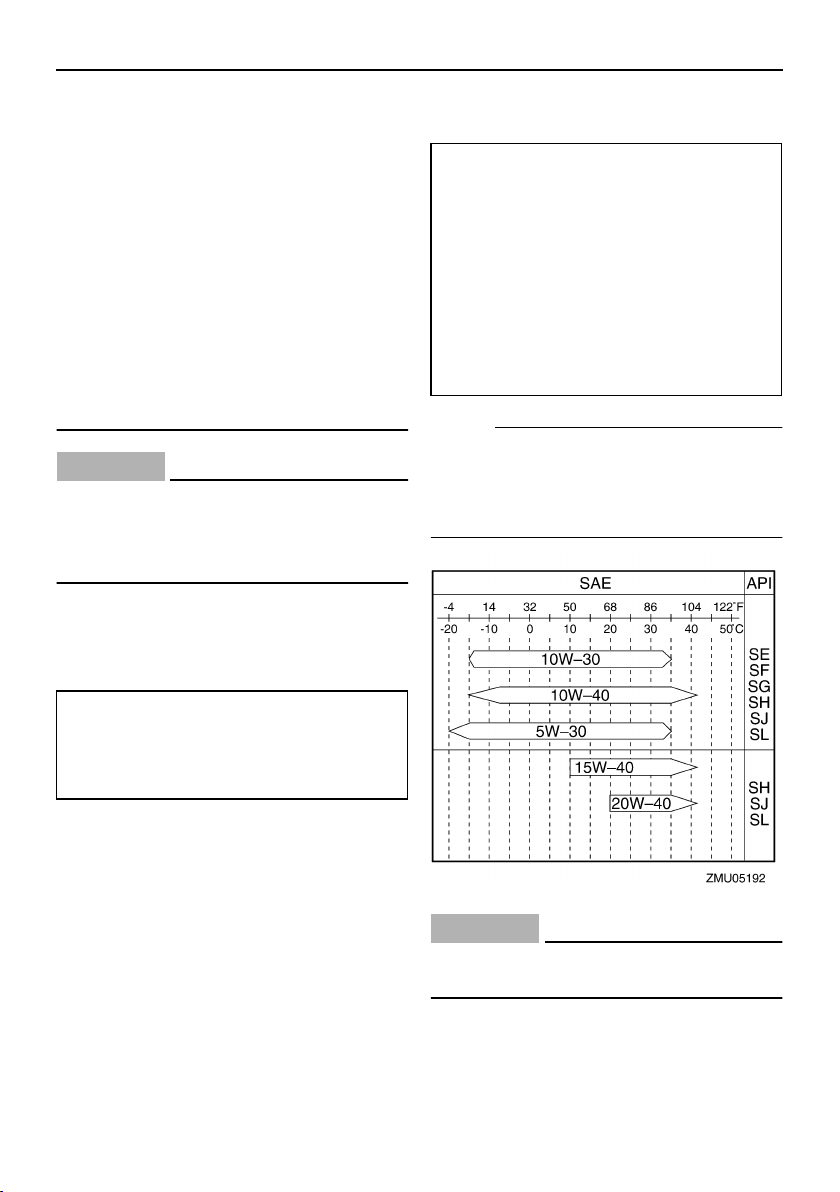
EMU31440
Engine oil
Recommended engine oil:
YAMALUBE 4-M FC-W oil or 4-stroke
motor oil with a combination of the following SAE and API oil classifications
Engine oil type SAE:
10W-30 or 10W-40
Engine oil grade API:
SE, SF, SG, SH, SJ, SL
Engine oil quantity (excluding oil filter):
1.6 L (1.69 US qt) (1.41 Imp.qt)
NOTE:
If the recommended engine oil grades are
not available, select an alternative from the
following chart according to the average
temperatures in your area.
Recommended gasoline:
Regular unleaded gasoline with a minimum octane rating of 86 (Pump Octane Number) = (R+M)/2
Gasohol
There are two types of gasohol: gasohol containing ethanol and that containing methanol. Gasohol containing ethanol can be used
if ethanol content does not exceed 10% and
the fuel meets minimum octane ratings.
Yamaha does not recommended gasohol
containing methanol because it can cause
fuel system damage or engine performance
problems.
10
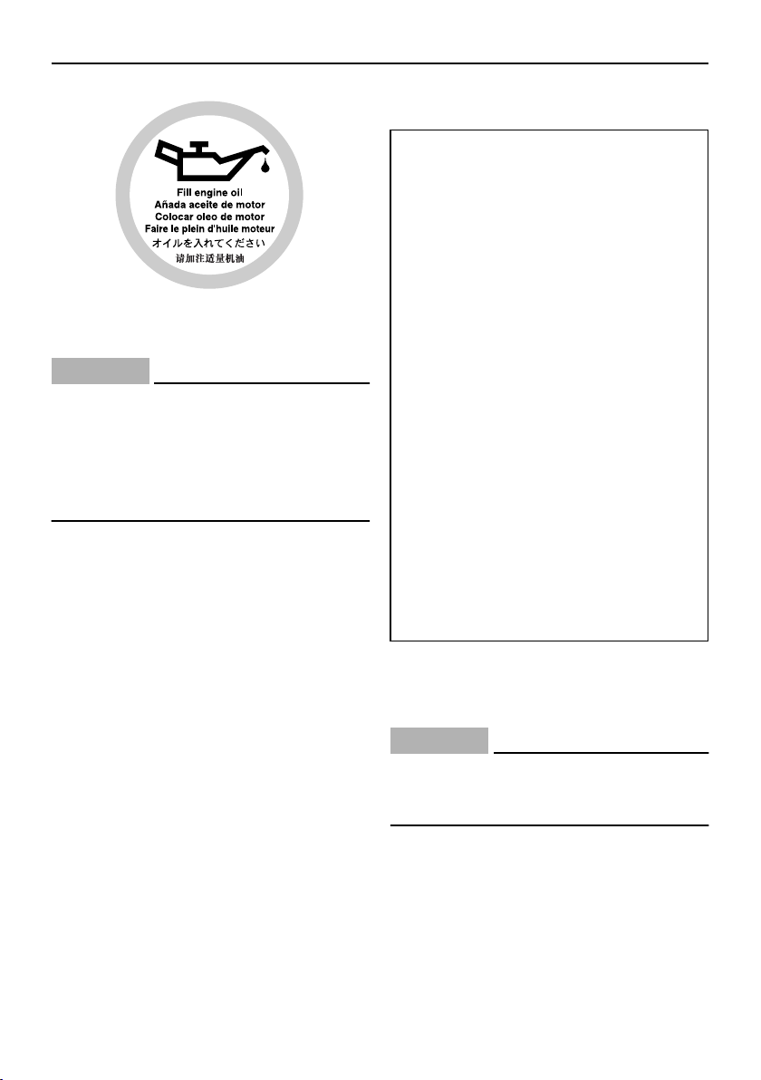
ECM01050
CAUTION:
All 4-stroke engines are shipped from the
factory without engine oil.
ZMU01710
EMU25690
Battery requirement
ECM01060
CAUTION:
Do not use a battery that does not meet
the specified capacity. If a battery which
does not meet specifications is used, the
electric system could perform poorly or
be overloaded, causing electric system
damage.
For electric start models, choose a battery
which meets the following specifications.
General information
EMU25711
Battery specifications
Minimum cold cranking amps (CCA/
SAE):
F15CEH 245.0 A
F15CPH 245.0 A
F20EH 245.0 A
F20ER 245.0 A
F20PH 245.0 A
F20PR 245.0 A
Minimum marine cranking amps (MCA/
ABYC):
F15CEH 323.0 A
F15CPH 323.0 A
F20EH 323.0 A
F20ER 323.0 A
F20PH 323.0 A
F20PR 323.0 A
Minimum reserve capacity (RC/SAE):
F15CEH 52 minutes
F15CPH 52 minutes
F20EH 52 minutes
F20ER 52 minutes
F20PH 52 minutes
F20PR 52 minutes
EMU25730
Without a rectifier or Rectifier Regulator
ECM01090
CAUTION:
A battery cannot be connected to models
that do not have a rectifier or Rectifier
Regulator.
If you wish to use a battery with the models
without a rectifier or Rectifier Regulator, install an optional Rectifier Regulator.
Using a maintenance-free battery with the
above models can shorten the life of the battery significantly.
Install an optional Rectifier Regulator or use
11
General information
accessories rated to withstand 18 volts or
higher with the above models. Consult your
Yamaha dealer for details on installing an
optional Rectifier Regulator.
EMU25742
Propeller selection
The performance of your outboard motor will
be critically affected by your choice of propeller, as an incorrect choice could adversely
affect performance and could also seriously
damage the motor. Engine speed depends
on the propeller size and boat load. If engine
speed is too high or too low for good engine
performance, this will have an adverse effect
on the engine.
Yamaha outboard motors are fitted with propellers chosen to perform well over a range
of applications, but there may be uses where
a propeller with a different pitch would be
more appropriate. For a greater operating
load, a smaller-pitch propeller is more suitable as it enables the correct engine speed
to be maintained. Conversely, a larger-pitch
propeller is more suitable for a smaller operating load.
Yamaha dealers stock a range of propellers,
and can advise you and install a propeller on
your outboard that is best suited to your application.
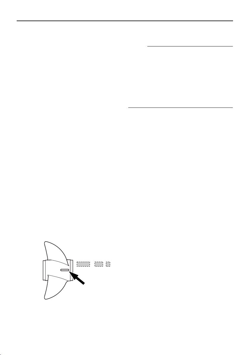
3. Type of propeller (propeller mark)
NOTE:
Select a propeller which will allow the engine
to reach the middle or upper half of the operating range at full throttle with the maximum
boat load. If operating conditions such as
light boat loads then allow the engine r/min to
rise above the maximum recommended
range, reduce the throttle setting to maintain
the engine in the proper operating range.
For instructions on propeller removal and installation, see page 66.
EMU25770
Start-in-gear protection
Yamaha outboard motors or Yamaha-approved remote control units are equipped
with start-in-gear protection device(s). This
feature permits the engine to be started only
when it is in neutral. Always select neutral
before starting the engine.
1. Propeller diameter in inches
2. Propeller pitch in inches
12
x
-
123
ZMU04605
Basic components
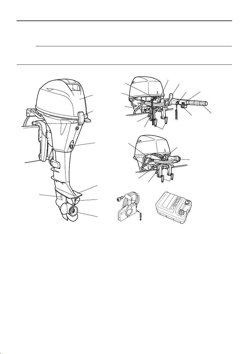
EMU25799
Main components
NOTE:
* May not be exactly as shown; also may not be included as standard equipment on all models.
F15C, F20
19
1
18
8
9
10
11
2
3
4
7
5
6
1. Top cowling
2. Top cowling lock lever
3. Drain screw
4. Anti-cavitation plate
5. Trim tab
6. Propeller
7. Cooling water inlet
8. Warning indicator(s)
9. Gear shift lever*
10. Engine stop button/Engine stop lanyard
switch*
11. Throttle friction adjuster*
12. Throttle grip*
13. Power trim and tilt switch*
17
13
16
15
18
14
8
13
17
16
20
14. Clamp screw
15. Steering friction lever*
16. Rope attachment
17. Tilt support knob*
18. Flushing device
19. Starter button*
20. Remote control box (side mount type)*
21. Fuel tank*
EMU25802
Fuel tank
If your model was equipped with a portable
14
21
12
ZMU05518
13
Basic components
fuel tank, its function is as follows.
EWM00020
WARNING
The fuel tank supplied with this engine is
its dedicated fuel reservoir and must not
be used as a fuel storage container. Commercial users should conform to relevant
licensing or approval authority regulations.
2
1
4
3
ZMU02284
1. Fuel joint
2. Fuel gauge
3. Fuel tank cap
4. Air vent screw
EMU25830
Fuel joint
This joint is used to connect the fuel line.
EMU25841
Fuel gauge
This gauge is located on either the fuel tank
cap or on the fuel joint base. It shows the approximate amount of fuel remaining in the
tank.
EMU25850
Fuel tank cap
This cap seals the fuel tank. When removed,
the tank can be filled with fuel. To remove the
cap, turn it counterclockwise.
EMU25860
Air vent screw
This screw is on the fuel tank cap. To loosen
the screw, turn it counterclockwise.
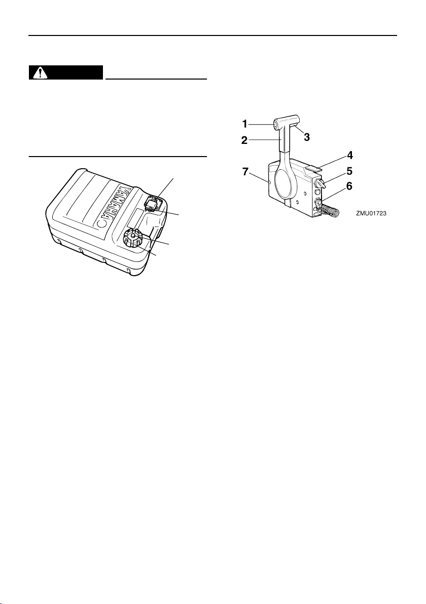
EMU26180
Remote control
The remote control lever actuates both the
shifter and the throttle. The electrical switches are mounted on the remote control box.
1. Power trim and tilt switch
2. Remote control lever
3. Neutral interlock trigger
4. Neutral throttle lever
5. Main switch / choke switch
6. Engine stop lanyard switch
7. Throttle friction adjuster
EMU26190
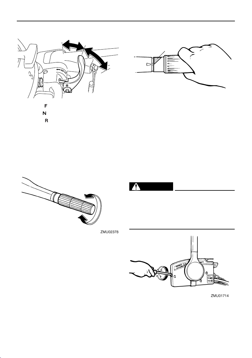
Remote control lever
Moving the lever forward from the neutral position engages forward gear. Pulling the lever back from neutral engages reverse. The
engine will continue to run at idle until the lever is moved about 35° (a detent can be felt).
Moving the lever farther opens the throttle,
and the engine will begin to accelerate.
14
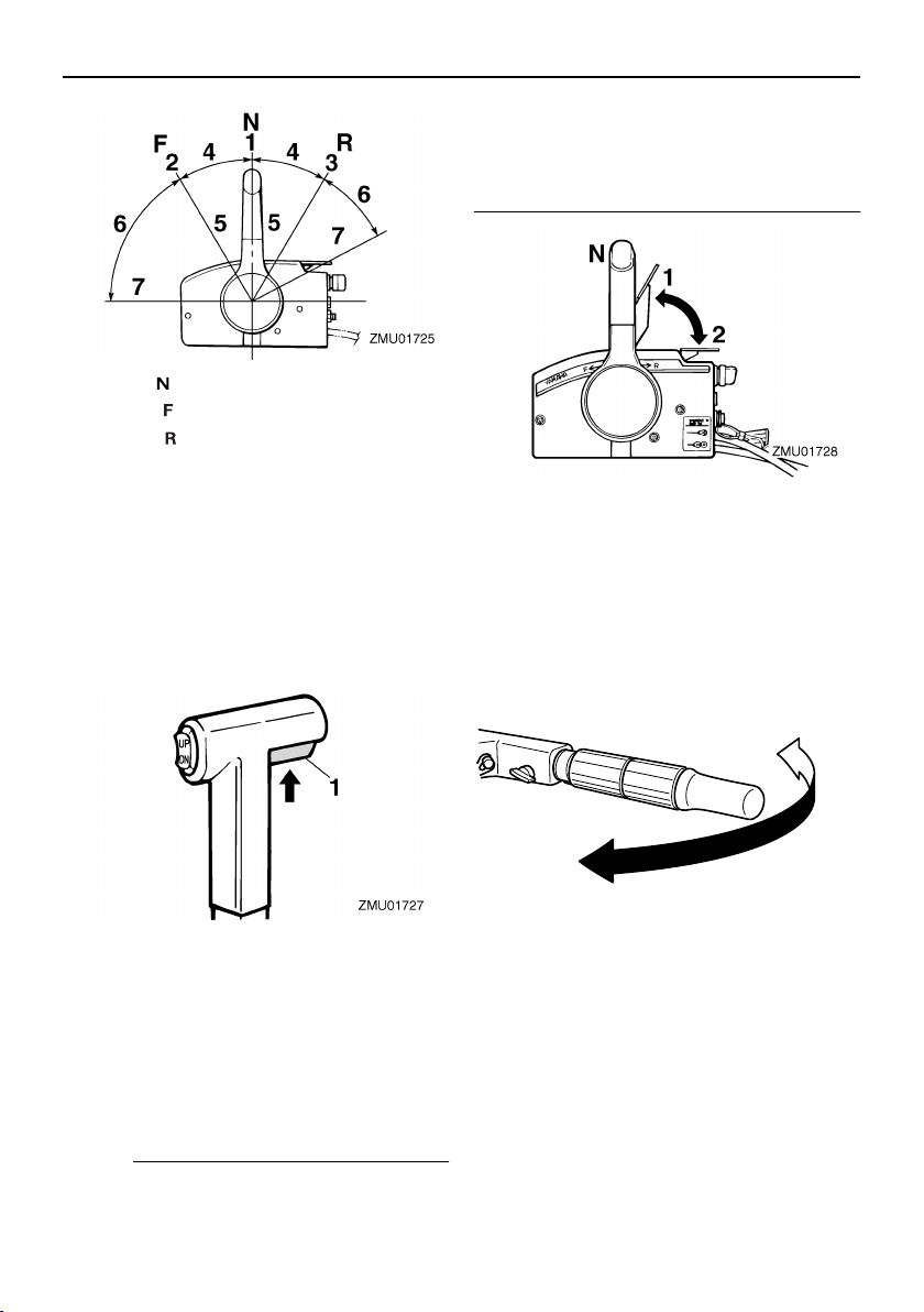
1. Neutral “”
2. Forward “”
3. Reverse “”
4. Shift
5. Fully closed
6. Throttle
7. Fully open
EMU26201
Neutral interlock trigger
To shift out of neutral, first pull the neutral interlock trigger up.
Basic components
when the remote control lever is in neutral.
The remote control lever will operate only
when the neutral throttle lever is in the closed
position.
1. Fully open
2. Fully closed
EMU25911
Tiller handle
To change direction, move the tiller handle to
the left or right as necessary.
1. Neutral interlock trigger
EMU26211
Neutral throttle lever
To open the throttle without shifting into either forward or reverse, put the remote control lever in the neutral position and lift the
neutral throttle lever.
NOTE:
The neutral throttle lever will operate only
ZMU01997
EMU25922
Gear shift lever
Pulling the gear shift lever towards you puts
the engine in forward gear so that the boat
moves ahead. Pushing the lever away from
you puts the engine in reverse gear so that
the boat moves astern.
15
Basic components
1. Forward “”
2. Neutral “”
3. Reverse “”
EMU25941
R
3
N
2
F
1
ZMU05519
Throttle grip
The throttle grip is on the tiller handle. Turn
the grip counterclockwise to increase speed
and clockwise to decrease speed.
1
ZMU05337
1. Throttle indicator
EMU25971
Throttle friction adjuster
A friction device provides adjustable resistance to movement of the throttle grip or the
remote control lever, and can be set according to operator preference.
To increase resistance, turn the adjuster
clockwise. To decrease resistance, turn the
adjuster counterclockwise.
EWM00031
WARNING
Do not overtighten the friction adjuster. If
there is too much resistance, it could be
difficult to move the remote control lever
or throttle grip, which could result in an
accident.
EMU25961
Throttle indicator
The fuel consumption curve on the throttle
indicator shows the relative amount of fuel
consumed for each throttle position. Choose
the setting that offers the best performance
and fuel economy for the desired operation.
16
ZMU02001
When constant speed is desired, tighten the
adjuster to maintain the desired throttle setting.
EMU25990
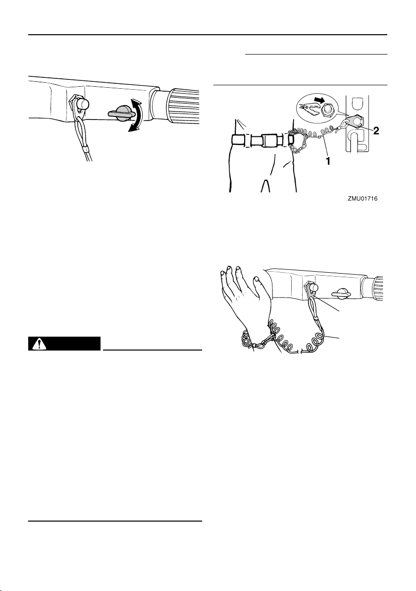
Engine stop lanyard switch
The lock plate must be attached to the engine stop switch for the engine to run. The
lanyard should be attached to a secure place
on the operator’s clothing, or arm or leg.
Should the operator fall overboard or leave
the helm, the lanyard will pull out the lock
plate, stopping ignition to the engine. This
will prevent the boat from running away under power.
EWM00120
WARNING
●
Attach the engine stop switch lanyard
to a secure place on your clothing, or
your arm or leg while operating.
●
Do not attach the lanyard to clothing
that could tear loose. Do not route the
lanyard where it could become entangled, preventing it from functioning.
●
Avoid accidentally pulling the lanyard
during normal operation. Loss of engine power means the loss of most
steering control. Also, without engine
power, the boat could slow rapidly. This
could cause people and objects in the
boat to be thrown forward.
Basic components
NOTE:
The engine cannot be started with the lock
plate removed.
1. Lanyard
2. Lock plate
2
1
ZMU02003
1. Lanyard
2. Lock plate
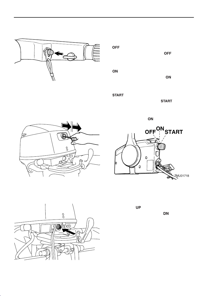
EMU26001
Engine stop button
To open the ignition circuit and stop the engine, push this button.
17
Basic components
ZMU02083
EMU26070
Manual starter handle
To start the engine, first gently pull the handle out until resistance is felt. From that position, then pull the handle straight out quickly
to crank the engine.
EMU26090
Main switch
The main switch controls the ignition system;
its operation is described below.
●
“”
(off)
With the main switch in the “” (off) posi-
tion, the electrical circuits are off, and the key
can be removed.
●
“”
(on)
With the main switch in the “” (on) posi-
tion, the electrical circuits are on, and the key
cannot be removed.
“”
●
With the main switch in the “” (start) po-
sition, the starter motor turns to start the engine. When the key is released, it returns
automatically to the “” (on) position.
(start)
ZMU05536
EMU26080
Starter button
To start the engine with the electric starter,
push the starter button.
ZMU05521
18
EMU26102
Power tilt switch
The power tilt system adjusts the outboard
motor angle in relation to the transom. Pushing the switch “” (up) tilts the outboard mo-
tor up. Pressing the switch “” (down) tilts
the outboard motor down. When the switch is
released, the outboard motor will stop in its
current position.
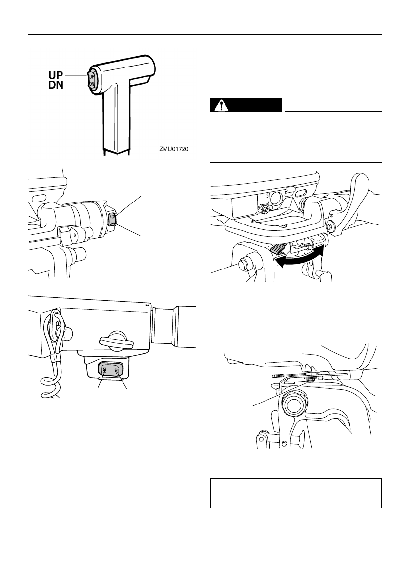
UP
DN
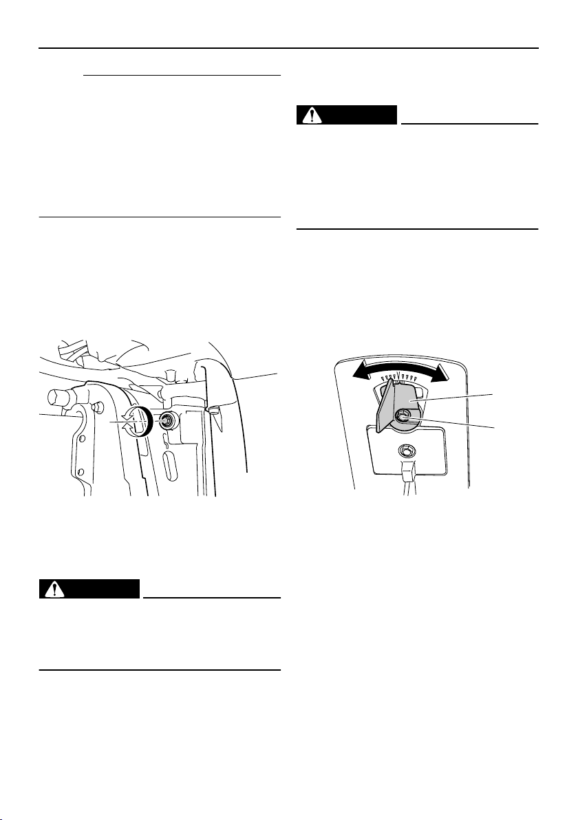
Basic components
To increase resistance, turn the lever to the
port side “A”.
To decrease resistance, turn the lever to the
starboard side “B”.
EWM00040
WARNING
Do not overtighten the friction adjuster. If
there is too much resistance, it could be
difficult to steer, which could result in an
accident.
A
ZMU05579
DN
UP
ZMU04899
NOTE:
For instructions on using the power tilt
switch, see pages 38 and 41.
EMU31431
Steering friction adjuster
A friction device provides adjustable resistance to the steering mechanism, and can be
set according to operator preference. An adjuster lever is located on the bottom of the
tiller handle bracket.
B
If the resistance does not increase even
when the lever is turned to the port side “A”,
make sure that the nut is tightened to the
specified torque.
ZMU05522
1
ZMU05523
1. Nut
Nut tightening torque:
5.8 Nm (4.3 ft-lb) (0.6 kgf-m)
19
Basic components
NOTE:
●
Steering movement is blocked when the
adjuster lever is set to the “A” position.
●
Check the tiller handle for smooth movement when the lever is turned to the starboard side “B”.
●
Do not apply lubricants such as grease to
the friction areas of the steering friction adjuster.
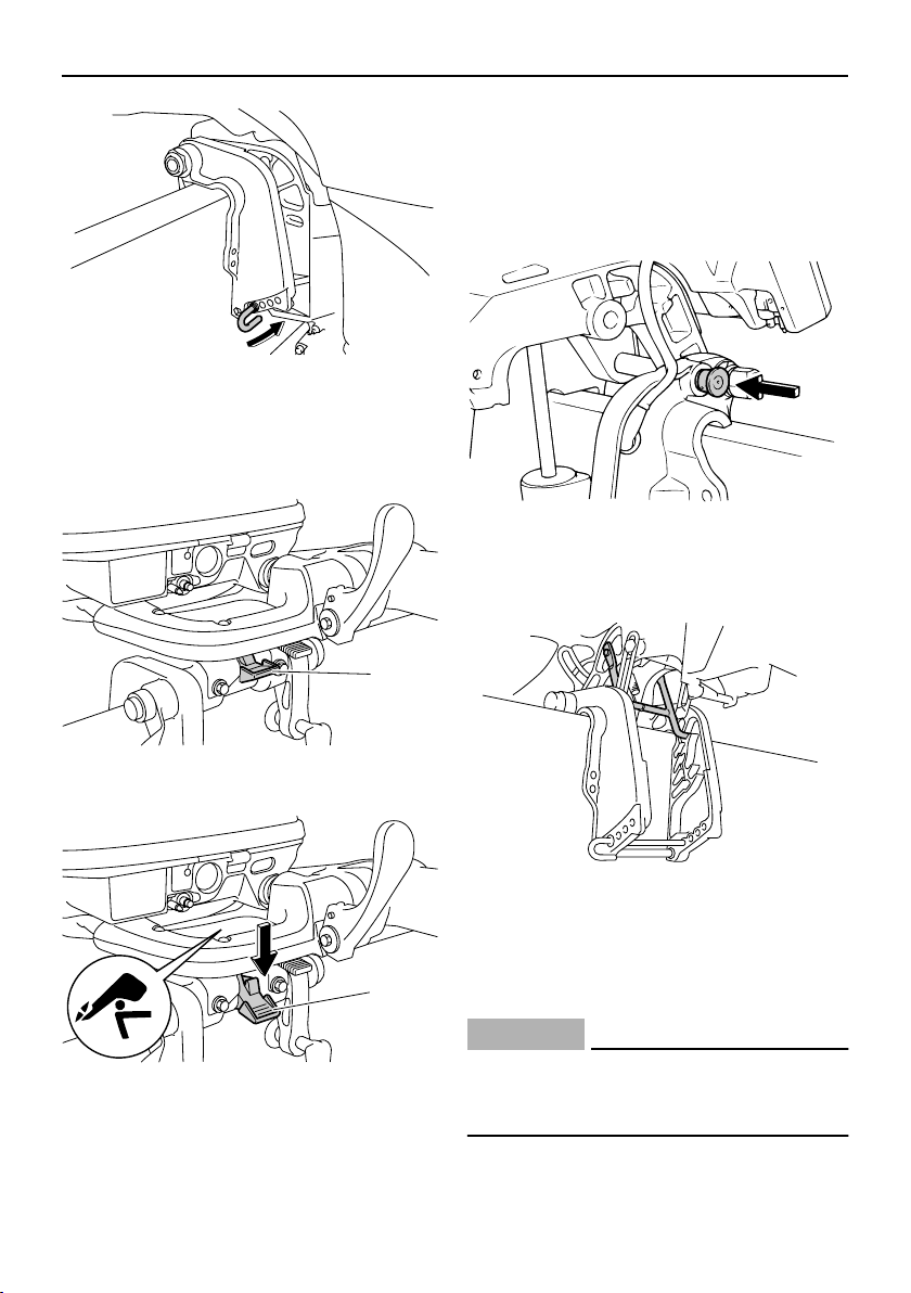
EMU26122
Steering friction adjuster
A friction device provides adjustable resistance to the steering mechanism, and can be
set according to operator preference. An adjusting screw or bolt is located on the swivel
bracket.
right or left by applying the same amount of
force.
EWM00840
WARNING
An improperly adjusted trim tab could
cause difficult steering. Always test run
after the trim tab has been installed or replaced to be sure steering is correct. Be
sure you have tightened the bolt after adjusting the trim tab.
If the boat tends to veer the left (port side),
turn the trim tab rear end to the port side “A”
in the figure.
If the boat tends to veer the right (starboard
side), turn the trim tab end to the starboard
side “B” in the figure.
A
B
1
2
ZMU02288
To increase resistance, turn the adjuster
clockwise.
To decrease resistance, turn the adjuster
counterclockwise.
EWM00040
WARNING
Do not overtighten the friction adjuster. If
there is too much resistance, it could be
difficult to steer, which could result in an
accident.
EMU26250
Trim tab
The trim tab should be adjusted so that the
steering control can be turned to either the
20
ZMU05524
1. Trim tab
2. Bolt
EMU26261
Trim rod (tilt pin)
The position of the trim rod determines the
minimum trim angle of the outboard motor in
relation to the transom.
ZMU05525
EMU30530
Tilt lock mechanism
The tilt lock mechanism is used to prevent
the outboard motor from lifting out of the water when in reverse gear.
1
Basic components
the release position.
EMU26320
Tilt support knob
To keep the outboard motor in the tilted up
position, push the tilt support knob under the
swivel bracket.
ZMU02812
EMU26330
Tilt support bar
The tilt support bar keeps the outboard motor
in the tilted up position.
ZMU05526
1. Tilt lock lever (Lock / tilt-down)
1
ZMU05631
1. Tilt lock lever (Release / tilt-up)
To lock it, set the tilt lock lever in the lock position. To release, push the tilt lock lever in
ZMU05528
EMU26360
Power tilt unit
This unit tilts the outboard motor up and
down and is controlled with the power tilt
switch.
ECM00630
CAUTION:
Do not step on or exert pressure on the
power tilt motor. The power tilt unit could
be damaged as a result.
21
Basic components
1
ZMU05597
1. Power tilt unit
2. Power tilt motor
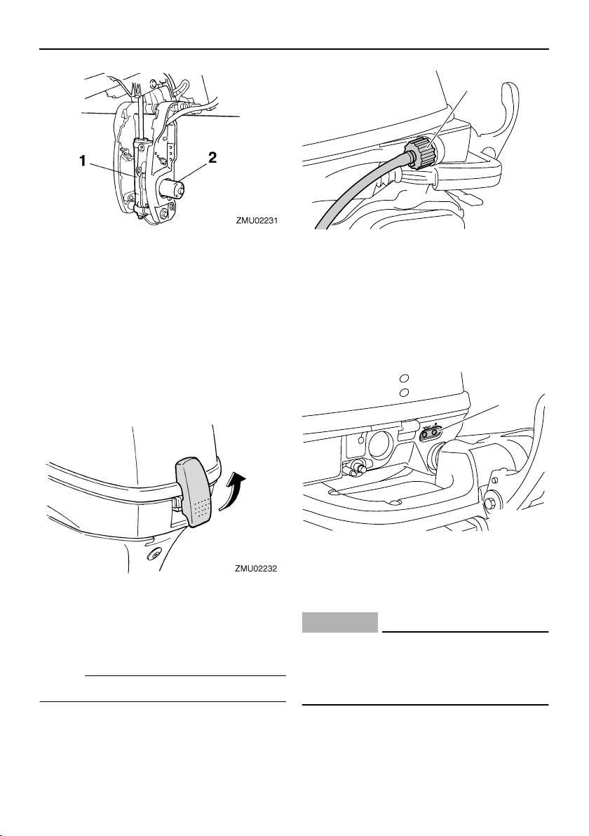
EMU26382
Top cowling lock lever (pull up type)
To remove the engine top cowling, pull up
the lock lever(s) and lift off the cowling.
When installing the cowling, check to be sure
it fits properly in the rubber seal. Then lock
the cowling by moving the lever(s) downward.
EMU26460
Flushing device
This device is used to clean the cooling water passages of the motor using a garden
hose and tap water.
NOTE:
For details on usage, see page 54.
1. Flushing device
EMU26302
Warning indicator
If the engine develops a condition which is
cause for warning, the indicator lights up. For
details on how to read the warning indicator,
see page 22.
1
ZMU05530
1. Warning indicator
EMU26801
Warning system
ECM00090
CAUTION:
Do not continue to operate the engine if a
warning device has activated. Consult
your Yamaha dealer if the problem cannot be located and corrected.
EMU26816
Overheat warning
This engine has an overheat warning device.
22
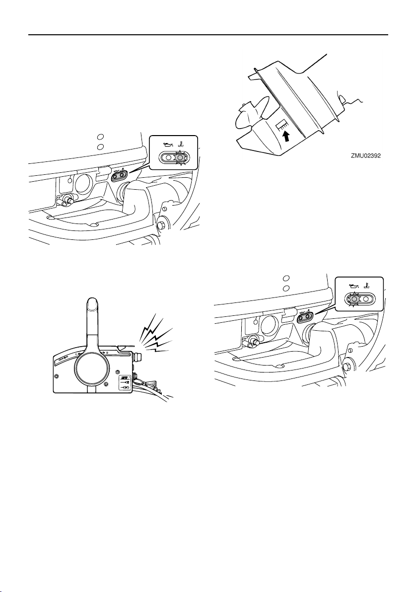
If the engine temperature rises too high, the
warning device will activate.
Activation of warning device
●
The engine speed will automatically decrease to about 2000 r/min.
●
If equipped with an overheat warning indicator, it will light or blink.
ZMU05592
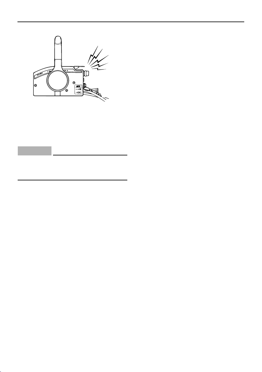
●
The buzzer will sound (if equipped on the
tiller handle, remote control box, or main
switch panel).
Basic components
EMU30167
Low oil pressure warning
If the oil pressure drops too low, the warning
device will activate.
Activation of warning device
●
The engine speed will automatically decrease to about 2000 r/min.
If equipped with a low oil pressure warning
●
indicator, it will light or blink.
ZMU02360
If the warning system has activated, stop the
engine and check the cooling water inlet for
clogging.
ZMU05531
●
The buzzer will sound (if equipped on the
tiller handle, remote control box, or main
switch panel).
23
Basic components
ZMU02360
If the warning system has activated, stop the
engine as soon as it is safe to do so. Check
the oil level and add oil as needed. If the oil
level is correct and the warning device does
not switch off, consult your Yamaha dealer.
ECM00100
CAUTION:
Do not continue to run the engine if the
low oil pressure warning indicator is on.
Serious engine damage could occur.
24
 Loading...