


F200B
FL200B
F250G
FL250G
SERVICE MANUAL
6DX-28197-5P-11

Preface
This manual has been prepared by Yamaha primarily for use by Yamaha dealers and their trained
mechanics when performing maintenance procedures and repairs to Yamaha equipment. It has
been written to suit the needs of persons who have the Bronze Technical Certificate of the YTA
(Yamaha Technical Academy) marine or the equivalent basic understanding of the mechanical and
electrical concepts and procedures inherent in the work, for without such knowledge attempted
repairs or service to the equipment could render it unsafe or unfit for use.
Because Yamaha has a policy of continuously improving its products, models may differ in detail
from the descriptions and illustrations given in this publication. Use only the latest edition of this
manual. Authorized Yamaha dealers are notified periodically of modifications and significant
changes in specifications and procedures, and these are incorporated in successive editions of this
manual. Also, up-to-date parts information is available on YPEC-web. Additional information and
up-to-date information on Yamaha products and services are available on Yamaha Service Portal.
Important information
Particularly important information is distinguished in this manual by the following notations:
The Safety Alert Symbol means ATTENTION! BECOME ALERT! YOUR SAFETY IS
INVOLVED!
A WARNING indicates a hazardous situation which, if not avoided, could result in death or
serious injury.
A NOTICE indicates special precautions that must be taken to avoid damages to the outboard motor or other property.
TIP:
A TIP provides key information to make procedures easier or clearer.
F200B, FL200B, F250G, FL250G
SERVICE MANUAL
©2011 by Yamaha Motor Co., Ltd.
1st Edition, July 2011
All rights reserved.
Any reprinting or unauthorized use
without the written permission of
Yamaha Motor Co., Ltd.
is expressly prohibited.
Contents
General information
Specification
Technical features and description
Rigging information
Troubleshooting
Electrical system
GEN
INFO
SPEC
TECH
FEA
RIG
GING
TRBL
SHTG
ELEC
0
1
2
3
4
5
Fuel system
Power unit
Lower unit
Bracket unit
Maintenance
Index
FUEL
POWR
LOWR
BRKT
MNT
6
7
8
9
10
Appendix
A


GEN
INFO
General information
Safety while working ..................................................... 0-1
Rotating part............................................................................... 0-1
Hot part....................................................................................... 0-1
Electric shock ............................................................................. 0-1
Propeller ..................................................................................... 0-1
Handling of gasoline................................................................... 0-1
Ventilation................................................................................... 0-1
Self-protection ............................................................................ 0-2
Working with crane..................................................................... 0-2
Handling of gas torch ................................................................. 0-2
Part, lubricant, and sealant......................................................... 0-2
Handling of sealant..................................................................... 0-2
Special service tool .................................................................... 0-3
Tightening torque ....................................................................... 0-3
Non-reusable part....................................................................... 0-3
Disassembly and assembly........................................................ 0-3
0
How to use this manual ..................................................... 0-4
Manual format ............................................................................ 0-4
Abbreviation ............................................................................... 0-5
Lubricant, sealant, and thread locking agent.................. 0-7
Symbol ....................................................................................... 0-7
Special service tool............................................................ 0-9
GEN
INFO
General information
Safety while working
To prevent an accident or injury and to provide quality service, observe the following
safety procedures.
Rotating part
• Hands, feet, hair, jewelry, clothing, personal flotation device straps, and so on,
can become entangled with internal rotating
parts of the engine, resulting in serious
injury or death.
• Keep the top cowling installed whenever
possible. Do not remove or install the top
cowling when the engine is running.
• Only operate the engine with the top cowling removed according to the specific
instructions in the manual. Keep hands,
feet, hair, jewelry, clothing, personal flotation device straps, and so on, away from
any exposed moving parts.
Handling of gasoline
• Gasoline is highly flammable. Keep gasoline and all flammable products away from
heat, sparks, and open flames.
• Gasoline is poisonous and can cause injury
or death. Handle gasoline with care. Never
siphon gasoline by mouth. If you swallow
some gasoline, inhale a lot of gasoline
vapor, or get some gasoline in your eyes,
see your doctor immediately. If gasoline
spills on your skin, wash with soap and
water. If gasoline spills on your clothing,
change your clothes.
Hot part
During and after operation, engine parts are
hot enough to cause burns. Do not touch any
parts under the top cowling until the engine
has cooled.
Electric shock
Do not touch any electrical parts while starting or operating the engine. Otherwise, shock
or electrocution could result.
Propeller
Do not hold the propeller with your hands
when loosening or tightening the propeller
nut.
Ventilation
• Gasoline vapor and exhaust gas are
heavier than air and extremely poisonous.
If gasoline vapor or exhaust gas is inhaled
in large quantities, it may cause loss of consciousness and death within a short time.
• When test running an engine indoors (for
example, in a water tank) make sure to do
so where adequate ventilation can be maintained.
0-1
Safety while working
Self-protection
• Protect your eyes by wearing safety
glasses or safety goggles during all operations involving drilling and grinding, or when
using an air compressor.
• Protect your hands and feet by wearing
protective gloves and safety shoes when
necessary.
Working with crane
• Outboard motors weighing 18.0 kg (39.7 lb)
and over must be carried by a crane.
• Use the wire ropes of adequate strength,
and lift up the outboard motor using the
three point suspension.
• If the outboard motor does not have three
or more points to be suspended, support it
using additional ropes or the like so that the
outboard motor can be lifted and carried in
a stable manner.
Handling of gas torch
• Improper handling of a gas torch may result
in burns. For information on the proper handling of the gas torch, see the operation
manual issued by the manufacturer.
• When using a gas torch, keep it away from
the gasoline and oil, to prevent a fire.
• Components become hot enough to cause
burns. Do not touch any hot components
directly.
Part, lubricant, and sealant
Use only genuine Yamaha parts, lubricants,
and sealants, or those recommended by
Yamaha, when servicing or repairing the outboard motor.
0
Handling of sealant
• Wear protective gloves to protect your skin,
when using the sealants.
• See the material safety data sheet issued
by the manufacturer. Some of the sealants
may be harmful to human health.
0-2
GEN
INFO
General information
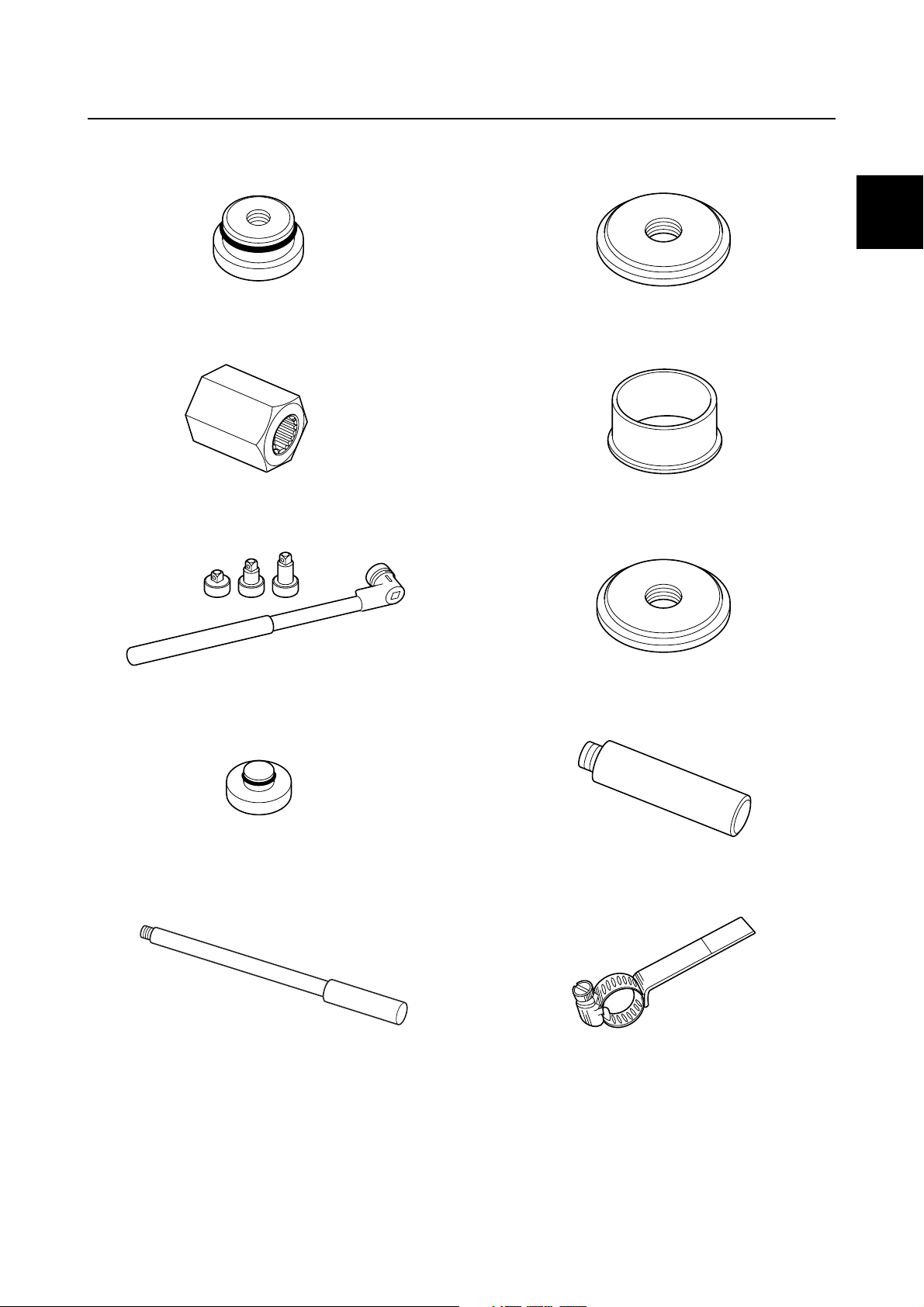
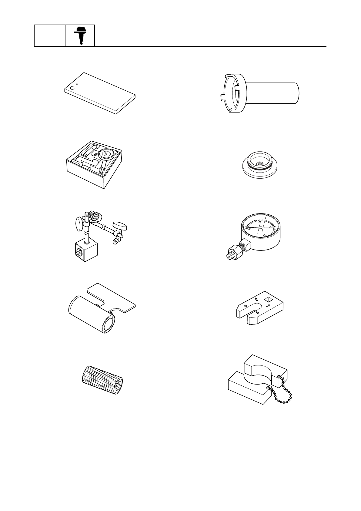
Special service tool
Use the recommended special service tools
to work safely, and to protect parts from damage.
Tightening torque
Follow the tightening torque specifications
provided throughout the manual. When tightening nuts, bolts, and screws, tighten the
large sizes first, and tighten fasteners starting
in the center and moving outward.
Non-reusable part
Always use new gaskets, seals, O-rings, cotter pins, and so on, when installing or assembling parts.
Disassembly and assembly
• Use compressed air to remove dust and dirt
during disassembly.
• Apply engine oil to the contact surfaces of
moving parts before assembly.
• Install bearings so that the bearing identification mark is facing in the direction indicated in the installation procedure. In
addition, make sure to lubricate the bearings liberally.
• Apply a thin coat of water resistant grease
to the lip and periphery of an oil seal before
installation.
• Check that moving parts operate normally
after assembly.
0-3
Safety while working / How to use this manual
How to use this manual
Manual format
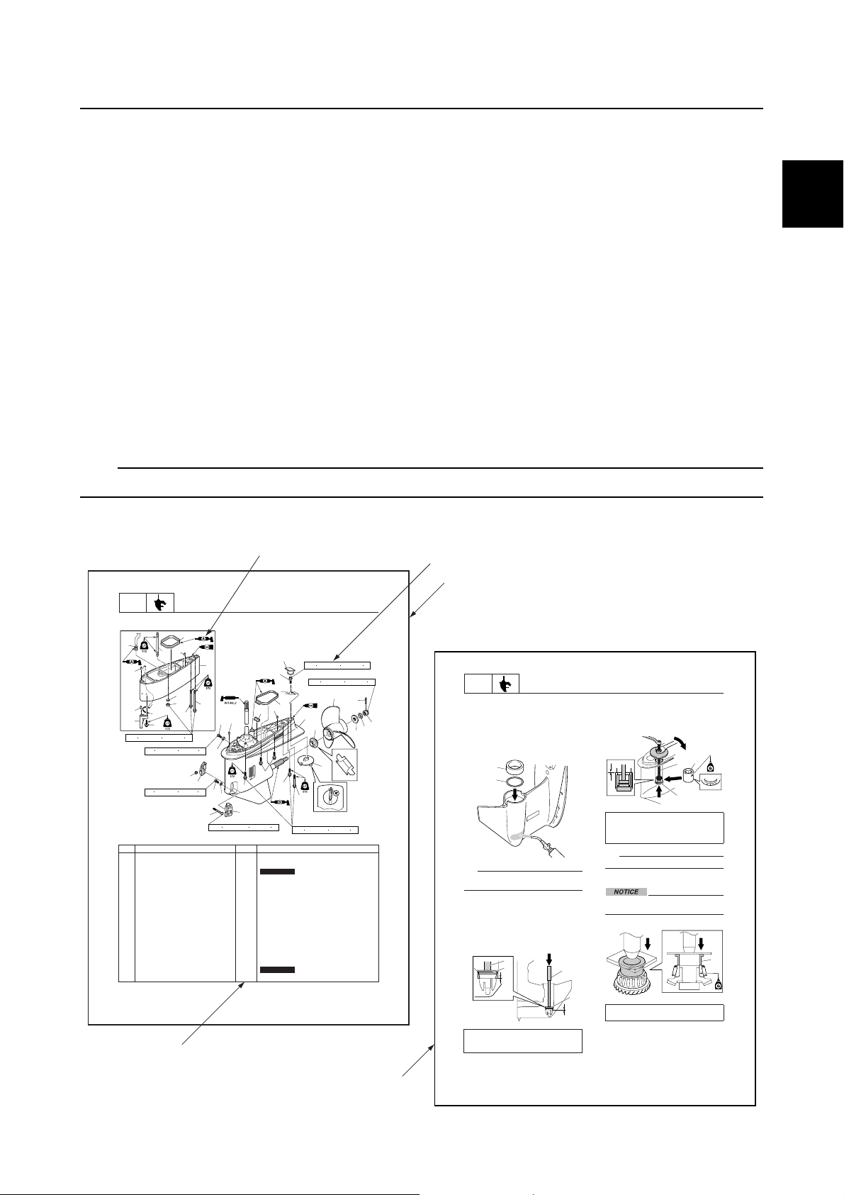
The format of this manual has been designed to make service procedures clear and easy to understand. Use the following information as a guide for effective and quality service.
• Parts are shown and detailed in an exploded diagram and are listed in the component list (see 1
in the following figure for an example page).
• The component list consists of part names and quantities, as well as bolt and screw dimensions
(see 2 in the following figure).
• Symbols are used to indicate important aspects of a procedure, such as the grade of lubricant and
the lubrication points (see 3 in the following figure).
• Tightening torque specifications are provided in the exploded diagrams (see 4 in the following fig-
ure), and in the related detailed instructions. Some torque specifications are listed in stages as
torque figures or angles in degrees.
• Separate procedures and illustrations are used to explain the details of removal, checking, and
installation where necessary (see 5 in the following figure for an example page).
TIP:
For troubleshooting procedures, see Chapter 4, “Troubleshooting.”
0
3
LOWR
Lower unit (regular rotation model)
È
26
25
24
23
47 N
No. Part name Q’ty Remarks
1 Water inlet cover (PORT) 1
2 Bolt 1 M5 40 mm
3Gasket 2
4 Drain screw 1
5 Water inlet cover (STBD) 1
6 Self-locking nut 1
7 Check screw 1
8Dowel 2
9Plate 1
10 Rubber seal 1
11 Bolt 1 M10 45 mm
12 Grommet 1
13 Lower unit 1
14 Spacer 1
15 Propeller 1
16 Cotter pin 1
17 Propeller nut 1
È U-transom model
8-1
Lower unit
25
27
33
32
31
34
35
m (4.7 kgf m, 34.7 ft lb)
9 N
m (0.9 kgf m, 6.6 ft lb)
9 N m (0.9 kgf m, 6.6 ft lb)
28
6
29
30
5
2
2.3 N
8
7
3
22
4
3
1
m (0.23 kgf m, 1.70 ft lb)
12
11
8
9
22
22
x
Not reusable
x
Not reusable
42 N m (4.2 kgf m, 31.0 ft lb)
10
13
21
47 N
m (4.7 kgf m, 34.7 ft lb)
54 N
2
m (5.4 kgf m, 39.8 ft lb)
15
14
20
4
1
LOWR
16
17
18
19
2. Heat the installation area of the taper
roller bearing outer race in the lower case
with a gas torch, and then install the
outer race 2.
the lower case, heat the entire
installation area evenly. Otherwise,
the paint on the lower case could be
burned.
TIP:
Do not reuse a shim if it is any deformed or
scratched.
3. While holding the special service tool 3,
strike the tool to check that the taper
roller bearing outer race is installed
properly. If a high-pitched metallic sound
is produced when the special service tool
is struck, the outer race is installed
properly.
Driver rod LL 3: 90890-06605
Bearing outer race attachment 4:
90890-06658
Lower unit
NOTICE:
When heating
2
1
3
4
3
4. Install the rollers into the needle bearing
outer race, and install the special service
tool into the needle bearing assembly 5,
and then install the needle bearing
assembly 5.
Ball bearing attachment 6:
90890-06655
Bearing outer race puller assembly 7:
90890-06523
TIP:
The needle bearing contains 28 rollers.
Assembling the forward gear
Do not reuse the bearing, always replace
it with a new one.
1. Install a new taper roller bearing.
4
Bearing inner race attachment 1:
90890-06659
5
7
6
1
5
8-19
0-4

GEN
INFO
Abbreviation
The following abbreviations are used in this service manual.
Abbreviation Description
ABYC American Boat and Yacht Council
AFT Aft end
API American Petroleum Institute
APS Accelerator Position Sensor
ATF Automatic Transmission Fluid
AWG American Wire Gauge
BOW Bow end
BTDC Before Top Dead Center
C/E Check Engine
C/L Centerline
CCA Cold Cranking Ampere
DN Down side
DOHC Dual Over Head Camshaft
ECM Electronic Control Module
General information
EN European Norm (European standard)
ETV Electronic Throttle Valve
EX Exhaust
EXH Exhaust
FForward
GPS Global Positioning System
IEC International Electro-technical Commission
IN Intake
INT Intake
ISC Idle Speed Control
ISO International Organization for Standardization
LAN Local Area Network
N Neutral
OCV Oil Control Valve
PCV Pressure Control Valve
PORT Port side
PTT Power Trim and Tilt
R Reverse
RON Research Octane Number
SAE Society of Automotive Engineers
STBD Starboard side
SW Switch
TCI Transistor-Controlled Ignition
TDC Top Dead Center
0-5

Abbreviation Description
TPS Throttle Position Sensor
UP Upside
VCT Variable Camshaft Timing
W/F Water in Fuel
YDIS Yamaha Diagnostic System
How to use this manual
0
0-6
GEN
INFO
General information
Lubricant, sealant, and thread locking agent
Symbol
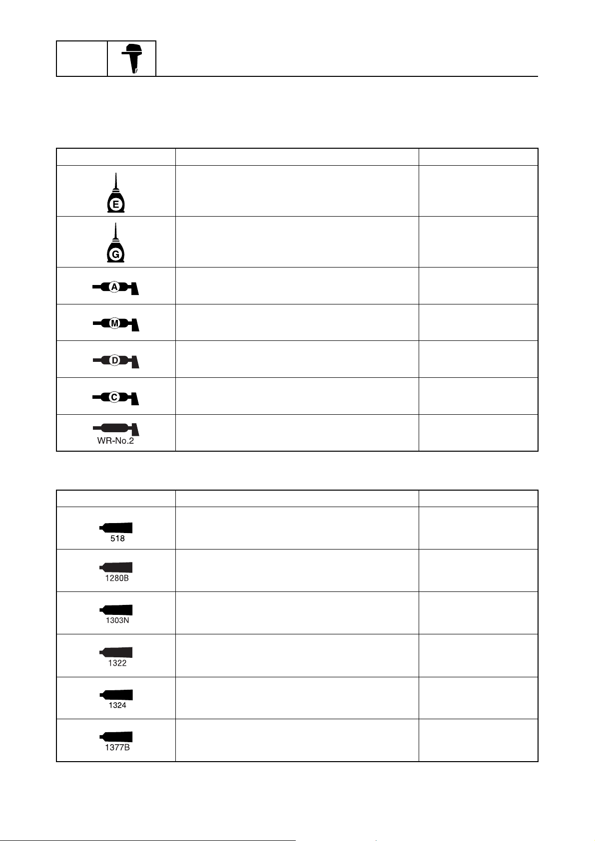
Symbols in an exploded diagram or illustration indicate the grade of lubricant and the lubrication
points.
Symbol Name Application
Yamaha 4-stroke motor oil Lubricant
Gear oil Lubricant
Water resistant grease
(Yamaha grease A)
Molybdenum disulfide grease Lubricant
Corrosion resistant grease
(Yamaha grease D)
Low temperature resistant grease
(Yamaha grease C)
WR-No.2 grease Lubricant
Symbols in an exploded diagram or illustration indicate the type of sealant or thread locking agent
and the application points.
Symbol Name Application
LOCTITE 518 Sealant
ThreeBond 1280B Sealant
Lubricant
Lubricant
Lubricant
0-7
ThreeBond 1303N Thread locking agent
ThreeBond 1322 Thread locking agent
ThreeBond 1324 Thread locking agent
ThreeBond 1377B Thread locking agent
Lubricant, sealant, and thread locking agent
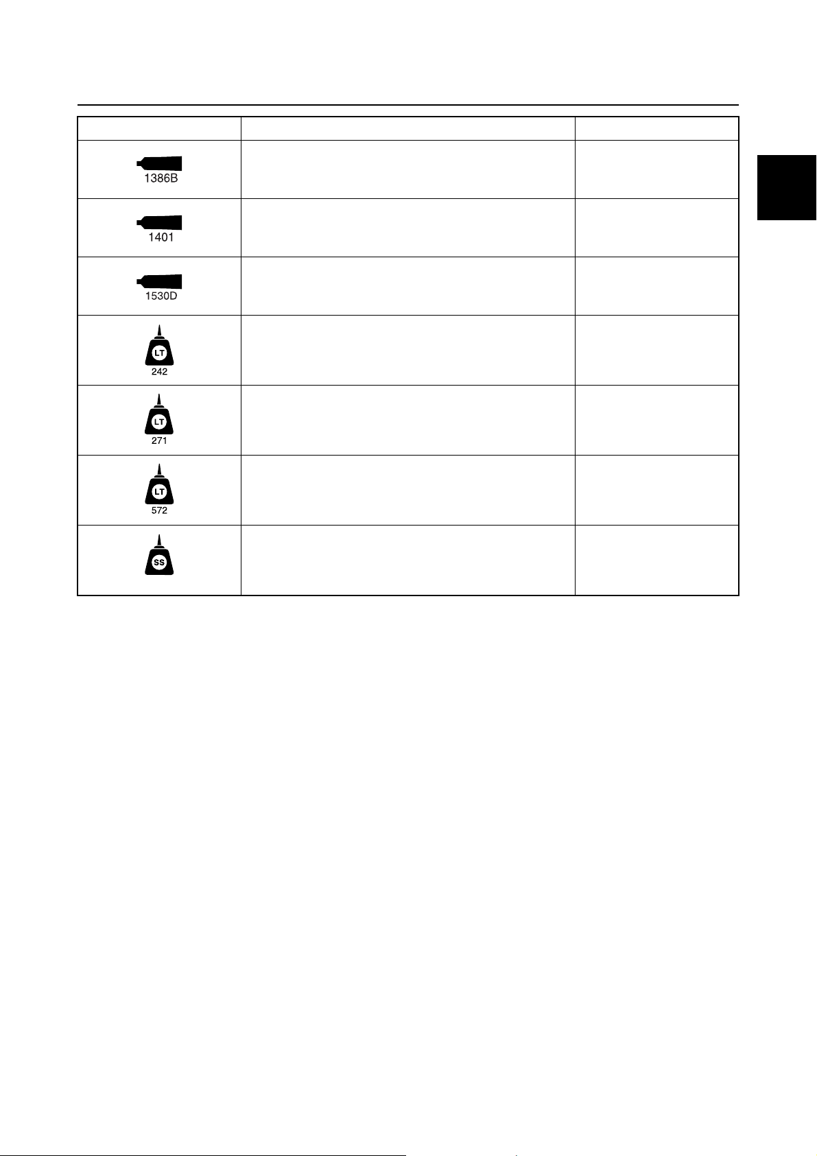
Symbol Name Application
ThreeBond 1386B Sealant
ThreeBond 1401 Thread locking agent
ThreeBond 1530D Sealant
LOCTITE 242 (blue) Thread locking agent
LOCTITE 271 (red) Thread locking agent
LOCTITE 572 (white) Sealant
0
Silicone sealant Sealant
0-8
GEN
INFO
General information
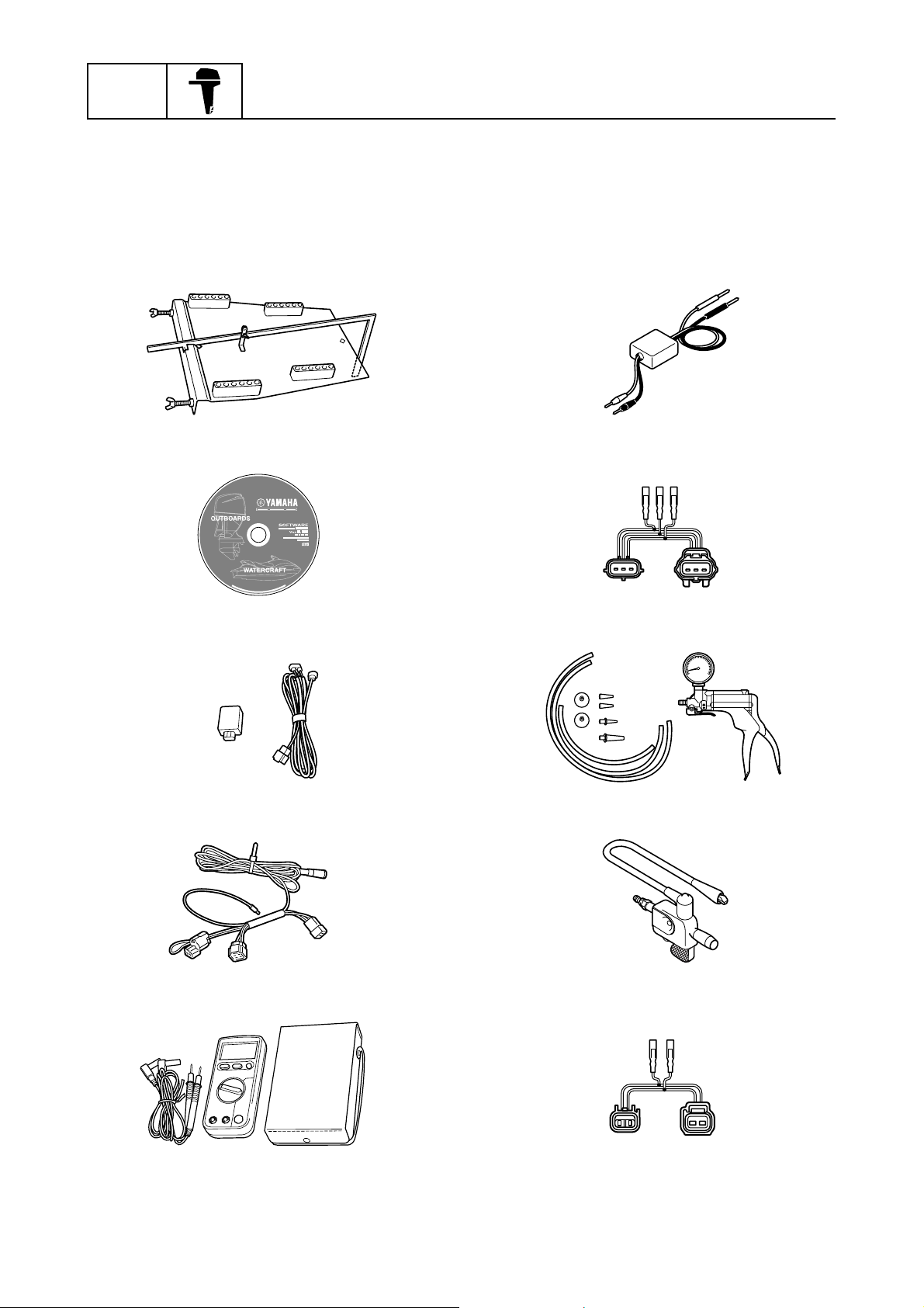
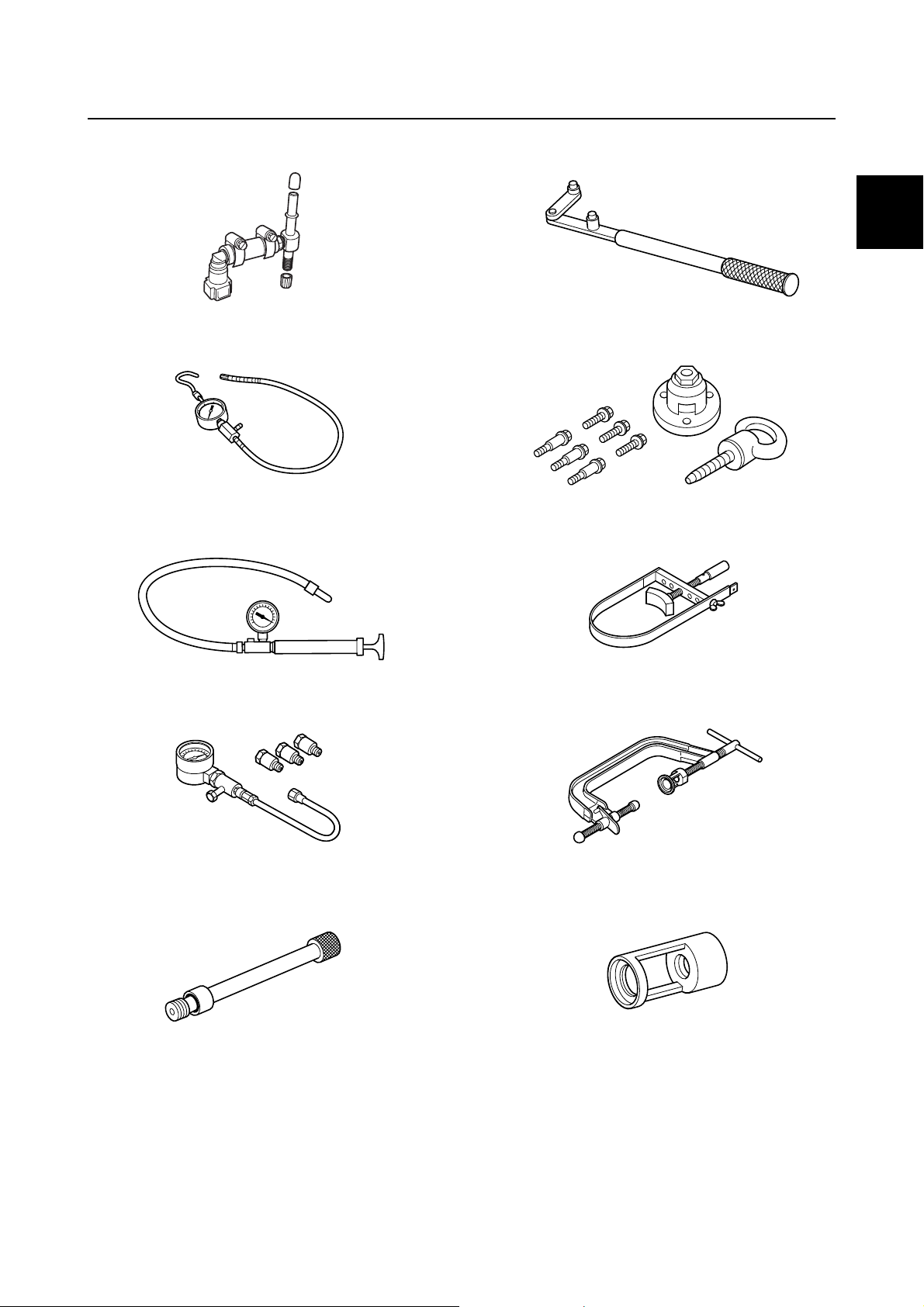
Special service tool
For all markets except U.S.A. and Canada
Special service tools with Yamaha part numbers (90890/60V-*****) are distributed by the Parts Division.
Drilling plate
90890-06783
YDIS (CD-ROM, Ver. 1.33)
60V-WS853-06
YDIS USB adapter and cable
60V-WS850-00
Peak voltage adapter
90890-03172
Test harness (3 pins)
90890-06869
Vacuum/pressure pump gauge set
90890-06756
Diagnostic flash indicator B
90890-06865
Digital circuit tester
90890-03174
0-9
Ignition tester
90890-06754
Test harness (2 pins)
90890-06867
Special service tool
Fuel pressure gauge adapter B
90890-06942
Fuel pressure gauge
90890-06786
Leakage tester
90890-06840
Flywheel magnet holder
90890-06522
0
Flywheel puller
90890-06521
Sheave holder
90890-01701
Compression gauge
90890-03160
Compression gauge extension
90890-06563
Valve spring compressor
90890-04019
Valve spring compressor attachment
90890-06320
0-10
GEN
INFO
General information
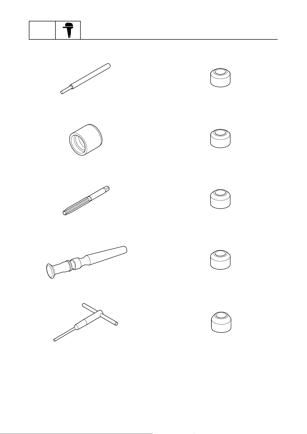
Valve guide remover/installer
90890-06801
Valve guide installer
90890-06810
Valve guide reamer
90890-06804
Valve seat cutter 30° (intake)
90890-06817
Valve seat cutter 30° (exhaust)
90890-06326
Valve seat cutter 45° (intake)
90890-06816
Valve lapper
90890-04101
Valve seat cutter holder
90890-06316
Valve seat cutter 45° (exhaust)
90890-06325
Valve seat cutter 60° (intake and exhaust)
90890-06324
0-11
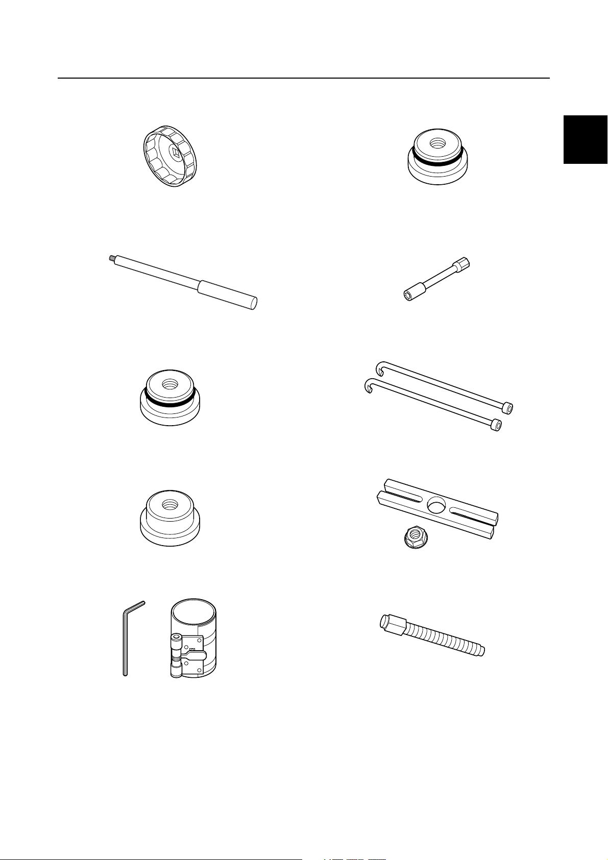
Special service tool
Oil filter wrench
90890-06830
Driver rod L3
90890-06652
Needle bearing attachment
90890-06613
Needle bearing attachment
90890-06653
0
Shift rod socket
90890-06679
Bearing housing puller claw L
90890-06502
Needle bearing attachment
90890-06607
Piston ring compressor
90890-05158
Stopper guide plate
90890-06501
Center bolt
90890-06504
0-12
GEN
INFO
General information
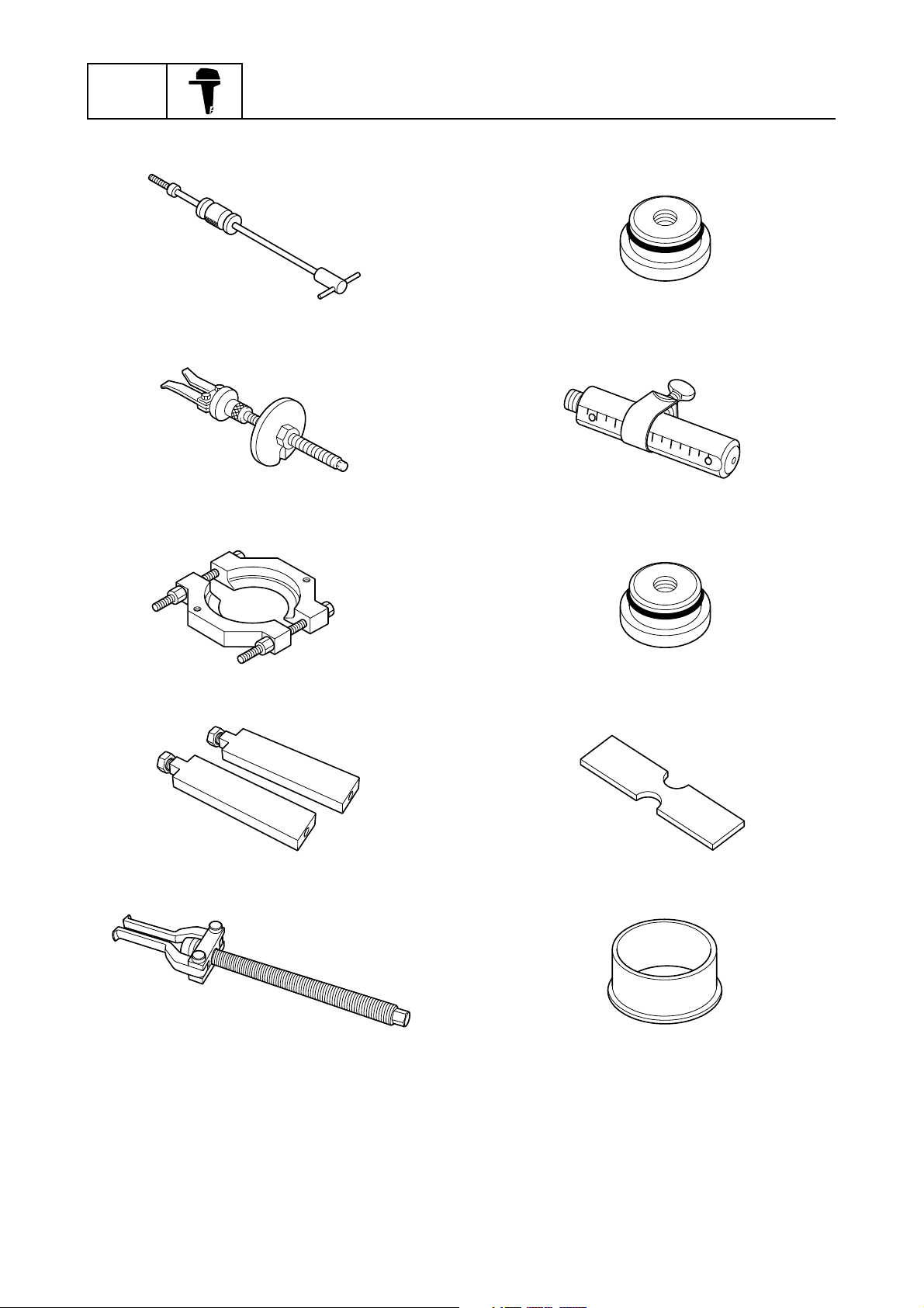
Slide hammer handle
90890-06531
Bearing outer race puller assembly
90890-06523
Bearing separator
90890-06534
Needle bearing attachment
90890-06611
Driver rod SS
90890-06604
Needle bearing attachment
90890-06610
Stopper guide stand
90890-06538
Bearing puller assembly
90890-06535
Bearing depth plate
90890-06603
Bearing inner race attachment
90890-06640
0-13
Special service tool
Needle bearing attachment
90890-06654
Drive shaft holder 6
90890-06520
Pinion nut holder
90890-06715
Bearing inner race attachment
90890-06658
0
Bearing inner race attachment
90890-06659
Bearing outer race attachment
90890-06628
Ball bearing attachment
90890-06655
Driver rod LL
90890-06605
Driver rod LS
90890-06606
Backlash indicator
90890-06706
0-14
GEN
INFO
General information
Magnet base plate
90890-07003
Dial gauge set
90890-01252
Magnet base B
90890-06844
Ring nut wrench
90890-06578
Ball bearing attachment
90890-06557
PTT oil pressure gauge assembly
90890-06580
Pinion height gauge
90890-06672
Puller head
90890-06514
Cylinder-end screw wrench
90890-06568
PTT piston vice attachment
90890-06572
0-15

Tilt rod wrench
90890-06569
Special service tool
0
0-16

SPEC
Specification
Model features.................................................................... 1-1
General feature .......................................................................... 1-1
Model designation ...................................................................... 1-2
Serial number ............................................................................. 1-3
Model data .......................................................................... 1-4
Dimension and weight ................................................................ 1-4
Performance............................................................................... 1-4
Power unit .................................................................................. 1-4
Lower unit................................................................................... 1-5
Bracket unit ................................................................................ 1-5
Fuel and oil requirement............................................................. 1-5
Battery requirement.................................................................... 1-6
PTT fluid requirement................................................................. 1-6
Electrical system technical data....................................... 1-7
Ignition timing control system ..................................................... 1-7
Fuel injection control system ...................................................... 1-8
Engine speed control system ..................................................... 1-8
VCT system................................................................................ 1-9
PTT system ................................................................................ 1-9
Charging system ...................................................................... 1-10
Starting system......................................................................... 1-10
Gauge/sensor........................................................................... 1-11
Fuel system technical data ............................................. 1-11
Fuel system .............................................................................. 1-11
Power unit technical data................................................ 1-12
Power unit ................................................................................ 1-12
Cylinder head assembly ........................................................... 1-12
Crankcase assembly ................................................................ 1-13
Lower unit technical data ................................................ 1-15
Lower unit assembly (regular rotation model) .......................... 1-15
Lower unit assembly (counter rotation model) ......................... 1-15
Bracket unit technical data ............................................. 1-16
PTT system .............................................................................. 1-16
Specified tightening torque............................................. 1-17
Rigging information .................................................................. 1-17
Fuel system .............................................................................. 1-17
Power unit ................................................................................ 1-17
Lower unit (regular rotation model) .......................................... 1-19

Lower unit (counter rotation model).......................................... 1-19
Bracket unit .............................................................................. 1-19
PTT unit.................................................................................... 1-20
General tightening torque ............................................... 1-21
1
SPEC
Specification
Model features
General feature
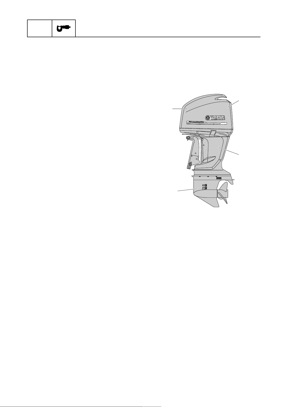
F200B, FL200B, F250G, and FL250G Overall feature
• Electronic fuel injected, 60° V6, DOHC, 24-valves, VCT, 3352.0 cm
• 6Y8 Multifunction Meter for easy rigging and precision engine information
• Low emission in compliance with EU regulation
a Power unit
• Shimless valve lifters
• Multi-point electronic fuel injection
• Blowby gas reburning system
• Vapor gas treatment system
• Single electronic throttle body
• Long intake manifolds
• Large diameter intake valve heads
• In-bank exhaust system
• Speed sensor and water pressure sensor
(optional)
b
3
(204.5 cu. in) engine
a
c
b Electrical
• Electronic fuel injection control
• Digital ignition control
• VCT control
• Knock control
• Over-rev control
• Self-diagnosis system
• ETV control
• Fail-safe control
• Conventional or LAN gauges acceptable
• Water-cooled Rectifier Regulator with isola-
tor
c Upper case
• Anodized exhaust passages
d Lower unit
• Hard chromeplated water pump (outer plate
cartridge and insert cartridge)
• Anodized lower case and propeller shaft
housing (F250G and FL250G)
• Drive shaft spring (F250G and FL250G)
• Propeller damper cooling system (F250G
and FL250G)
d
1-1

Model designation
F 250 G E T X
12 3 4 5
Model features
None: 2-stroke
E: Enduro
F: 4-stroke
1 Model category
2 Output horsepower Example: 6/9.9/75/150/250/300
3 Model generation A/B/C/D/F/G/H/J/L/N/P/Q/R/S/T/U/V/X/Y (Repeat from A)
4 Model variation
L: Counter rotating propeller
T: High thrust (4-stroke)
D: Twin rotating propeller
K: Kerosene
Z: HPDI
Level 1: Starting method
M: Manual start
E: Electric start
W: Electric start with manual start
Level 2: Control method
None: Remote control without tiller handle
H: Tiller handle
C: Remote control with tiller handle
Level 3: Trim and tilt method
None: Manual tilt
D: Hydraulic tilt
P: PT (Power tilt)
T: PT/T (Power trim and tilt)
1
Transom height
5
(Drive shaft length)
Level 4: Lubrication system (2-stroke model)
None: Premixed fuel with oil model
O: Oil injection model
S (15 in)
L (20 in)
Y (22.5 in)
X (25 in)
U (31 in)
1-2
SPEC
Specification
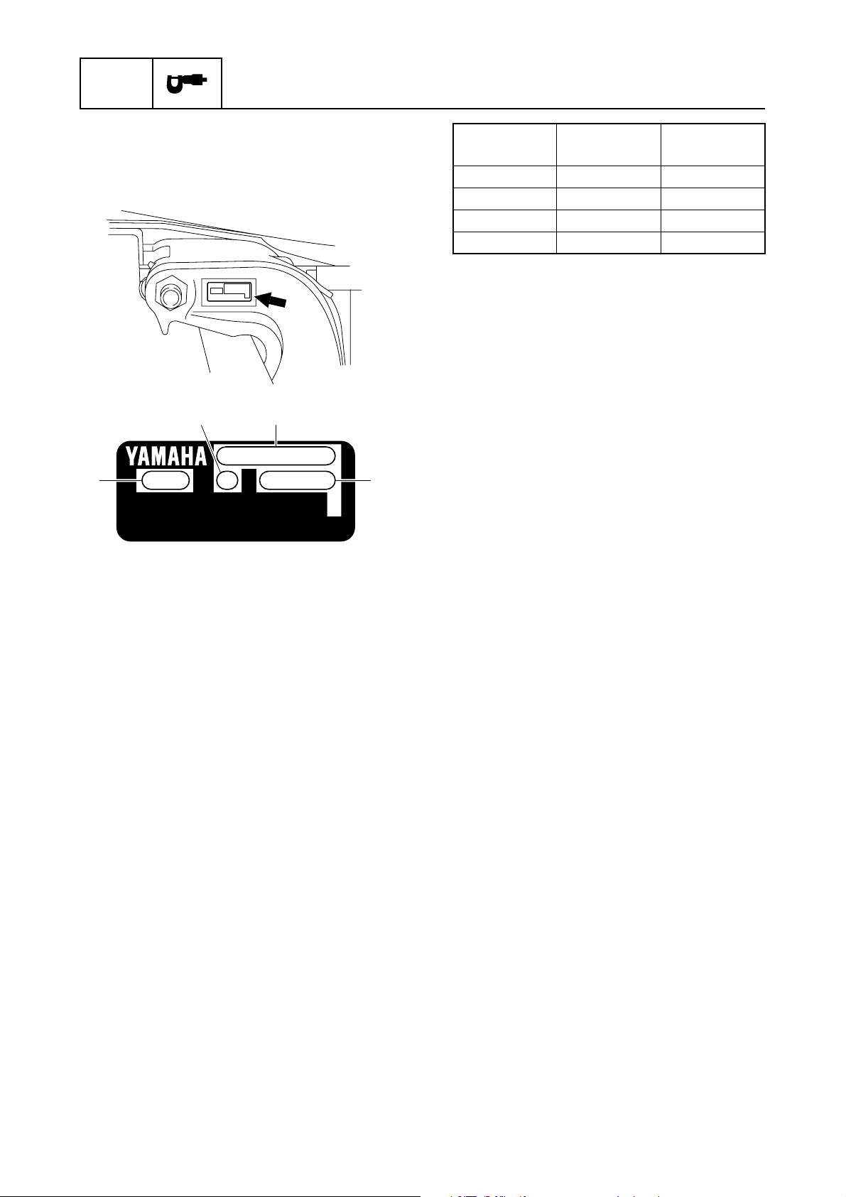
Serial number
The outboard motor serial number is indicated on a label affixed to the port clamp
bracket.
31
2
YAMAHA MOTOR CO., LTD.
MADE IN JAPAN
PAYS D'ORIGINE JAPON
4
Model name
Approved
model code
Starting
serial No.
F200BET 6S1 1002876–
FL200BET 6S2 1001074–
F250GET 6DX 1000001–
FL250GET 6DY 1000001–
1 Model name
2 Approved model code
3 Transom height
4 Serial number
1-3

Model data
Dimension and weight
Model features / Model data
Item Unit
Overall length mm (in)
Overall width mm (in) 634.0 (25.0)
Overall height
X mm (in)
U mm (in) 1956.0 (77.0)
Outboard motor transom height
X mm (in) 643.0 (25.3)
U mm (in) 770.0 (30.3)
Weight (SUS)
X kg (lb) 283.0 (624)
U kg (lb) 290.0 (639)
(*1) With SUS (stainless steel) propeller
(*1)
F200BET FL200BET F250GET FL250GET
Model
868.0 (34.2)
1829.0 (72.0)
Performance
Item Unit
Maximum output
At 5500 r/ min kW (HP)
Full throttle operating range r/min
Maximum fuel consumption
At 5500 r/min
Engine idle speed r/min
L (US gal,
Imp gal)/hr
F200BET FL200BET F250GET FL250GET
147.1 (200)
73.7 (19.5, 16.2) 75.6 (20.0, 16.6)
Model
5000–6000
600–700
1
183.9 (250)
Power unit
Item Unit
Type 4-stroke, DOHC
Cylinder quantity V6
Total displacement cm
Bore × stroke mm (in) 94.0 × 80.5 (3.70 × 3.17)
Compression ratio 9.9 : 1
Control system Remote control
Starting system Electric
Fuel system Fuel injection
Ignition control system TCI
Advance type Microcomputer
Maximum generator output V, A 12.0, 44.0
Spark plug LFR6A-11(NGK)
Firing order 1–2–3–4–5–6 (Normal operation)
Cooling system Water
Exhaust system Propeller boss
Lubrication system Wet sump
3
(cu. in) 3352.0 (204.5)
F200BET FL200BET F250GET FL250GET
Model
1-4

SPEC
Lower unit
Specification
Item Unit
Gear shift positions F-N-R
Gear ratio 2.00 (30/15)
Reduction gear type Spiral bevel gear
Clutch type Dog clutch
Propeller shaft type Spline
Propeller direction (rear view)
Propeller mark T, M TL, ML T, M TL, ML
F200BET FL200BET F250GET FL250GET
Clock-
wise
Counter-
clockwise
Model
Clock-
wise
Counter-
clockwise
Bracket unit
Item Unit
Trim angle
At 12° boat transom degree –3 to 16
Tilt-up angle degree 70
Steering angle degree 32 + 32
Trim and tilt system PTT
F200BET FL200BET F250GET FL250GET
Model
Fuel and oil requirement
Item Unit
Fuel type Regular unleaded gasoline
Minimum fuel octane number RON 84 90
Engine oil 4-stroke motor oil
Engine oil grade (*1) (*2) API SE, SF, SG, SH, SJ, SL
SAE 5W-30, 10W-30, 10W-40
Total engine oil quantity (oil pan
capacity) (*3)
Gear oil type Hypoid gear oil
Gear oil grade (*2)
Gear oil quantity
(*1) If the recommended engine oil grades are not available, use engine oil with an API classifica-
tion of SH, SJ, or SL and an SAE classification of 15W-40, 20W-40, or 20W-50.
(*2) Meeting both API and SAE requirements.
(*3) For actual engine oil amount required at periodical oil check, see “Power unit technical data”
(1-12).
L (US qt,
Imp qt)
API GL-4
SAE 90
L (US qt,
Imp qt)
F200BET FL200BET F250GET FL250GET
1.150
(1.216,
1.012)
(1.057,
0.880)
Model
5.6 (5.92, 4.93)
1.000
(1.216,
1.012)
1.150
1.000
(1.057,
0.880)
1-5

Battery requirement
Model data
Item Unit
Minimum cold cranking amps
CCA/EN A 711.0
Minimum rated capacity
20HR/IEC Ah 100.0
F200BET FL200BET F250GET FL250GET
Model
PTT fluid requirement
Item Unit
Fluid type ATF Dexron II
F200BET FL200BET F250GET FL250GET
Model
1
1-6

SPEC
Specification
Electrical system technical data
Ignition timing control system
Item Unit
Spark plug
Gap mm (in) 1.0–1.1 (0.039–0.043)
Ignition coil
Input voltage V 12.0
Pulser coil
Air gap mm (in) 1.4–1.6 (0.055–0.063)
Resistance (*1)
At 20 °C (68 °F) Ω 396.0–594.0
Output peak voltage
At cranking (unloaded) V 3.0
At cranking (loaded) V 2.7
At 1500 r/min (loaded) V 14.5
At 3500 r/min (loaded) V 17.8
Cam position sensor
Input voltage V 12.0
Knock sensor
Resistance (*1)
At 20 °C (68 °F) kΩ 504.0–616.0
Air temperature sensor
Resistance (*1)
At 20 °C (68 °F) kΩ 2.21–2.69
At 80 °C (176 °F) kΩ 0.32
Input voltage V 4.75–5.25
Neutral switch
Input voltage V 4.75–5.25
Air pressure sensor
Input voltage V 4.75–5.25
Output voltage
At –20.0 kPa (–0.20
kgf/cm
At –46.7 kPa (–0.467
kgf/cm
Engine temperature sensor
Resistance (*1)
At 20 °C (68 °F) kΩ 54.2–69.0
At 100 °C (212 °F) kΩ 3.12–3.48
Thermoswitch
Input voltage (*1) V 11.4
Temperature
Switch ON °C (°F) 84–90 (183–194)
Switch OFF °C (°F) 68–82 (154–180)
2
, –2.9 psi)
2
, –6.8 psi)
V3.21
V2.16
F200BET FL200BET F250GET FL250GET
Model
(*1) The figures are for reference only.
1-7

Fuel injection control system
Electrical system technical data
Item Unit
Fuel line
Pressure (*1)
Within 5 seconds after
engine start switch
turned to ON
At engine idle speed
Fuel injector
Resistance (*1)
At 20 °C (68 °F) Ω 12.0
Low-pressure fuel pump
Resistance (*1)
At 20 °C (68 °F) Ω 0.5–4.0
High-pressure fuel pump
Resistance (*1)
At 20 °C (68 °F) Ω 0.3–10.0
Vapor shut-off valve
Resistance (*1)
At 20 °C (68 °F) Ω 30.0–34.0
Water detection switch
Input voltage V 4.75–5.25
kPa
(kgf/cm
psi)
kPa
(kgf/cm
psi)
F200BET FL200BET F250GET FL250GET
2
,
2
,
290.0 (2.90, 42.1)
260.0 (2.60, 37.7)
Model
1
(*1) The figures are for reference only.
Engine speed control system
Item Unit
Oil pressure sensor
Input voltage V 4.75–5.25
Output voltage (*1)
At 392.0 kPa (3.92
kgf/cm
At 784.0 kPa (7.84
kgf/cm
APS
Resistance (*1)
With accelerator lever
fully closed
With accelerator lever
fully open
Output voltage (*1)
2
2
APS 1 and APS 2
APS 1 and APS 2
, 56.8 psi)
, 113.7 psi)
At 20 °C (68 °F) kΩ 0.8
At 20 °C (68 °F) kΩ 5.3
V2.5
V4.5
F200BET FL200BET F250GET FL250GET
Model
1-8

SPEC
Specification
Item Unit
With remote control lever
fully closed
APS 1 V 0.550–0.850
APS 2 V 0.400–1.000
With remote control lever
fully open
APS 1 and APS 2 V Above 3.250
TPS
Output voltage (*1)
With throttle valve fully
closed
TPS 1 V 0.500–0.700
With throttle valve fully
open
TPS 2 V 4.600–4.700
Shift cut switch
Input voltage V 4.75–5.25
(*1) The figures are for reference only.
F200BET FL200BET F250GET FL250GET
Model
VCT system
Item Unit
OCV
Resistance (*1)
At 20 °C (68 °F) Ω 6.7–7.7
Input voltage V 12.0
(*1) The figures are for reference only.
F200BET FL200BET F250GET FL250GET
PTT system
Item Unit
Trim sensor
Free position resistance (*1)
At 20 °C (68 °F) Ω 247.6–387.6
Setting resistance Ω 9.0–11.0
(*1) The figures are for reference only.
F200BET FL200BET F250GET FL250GET
Model
Model
1-9

Charging system
Electrical system technical data
Item Unit
Lighting coil
Resistance (*1)
At 20 °C (68 °F) Ω 0.11–0.17
Output peak voltage
At cranking (unloaded) V 8.3
At 1500 r/min (unloaded) V 44.7
At 3500 r/min (unloaded) V 97.7
Fuse A 60
Rectifier Regulator
Output peak voltage
At 1500 r/min (loaded) V 13.0
At 3500 r/min (loaded) V 13.0
(*1) The figures are for reference only.
F200BET FL200BET F250GET FL250GET
Model
Starting system
Item Unit
Starter motor
Type Sliding gear
Output kW 1.4
Cranking time limit second 30
Brush
Standard length mm (in) 15.5 (0.61)
Wear limit mm (in) 9.5 (0.37)
Commutator
Standard diameter mm (in) 29.0 (1.14)
Wear limit mm (in) 28.0 (1.10)
Standard undercut mm (in) 0.5–0.8 (0.02–0.03)
Wear limit mm (in) 0.2 (0.01)
F200BET FL200BET F250GET FL250GET
Model
1
1-10

SPEC
Gauge/sensor
Specification
Item Unit
F200BET FL200BET F250GET FL250GET
Model
Water pressure sensor
Input voltage V 4.75–5.25
Output voltage (*1)
At 392.0 kPa (3.92
2
kgf/cm
, 56.8 psi)
At 784.0 kPa (7.84
2
kgf/cm
, 113.7 psi)
V2.5
V4.5
Speed sensor
Input voltage V 4.75–5.25
Output voltage (*1)
At 392.0 kPa (3.92
2
kgf/cm
, 56.8 psi)
At 784.0 kPa (7.84
2
kgf/cm
, 113.7 psi)
V2.5
V4.5
(*1) The figures are for reference only.
Fuel system technical data
Fuel system
Item Unit
F200BET FL200BET F250GET FL250GET
Fuel filter assembly
Holding pressure
kPa
2
Positive pressure
(kgf/cm
,
psi)
kPa
Negative pressure
(kgf/cm
2
,
psi)
Primer pump
Holding pressure
kPa
2
Positive pressure
(kgf/cm
,
psi)
Vapor separator tank
Float height mm (in) 67.5 ± 2.5 (2.66 ± 0.10)
Canister
Holding pressure
kPa
2
Positive pressure
(kgf/cm
,
psi)
Model
200.0 (2.00, 29.0)
80.0 (0.80, 11.6)
170.0 (1.70, 24.7)
19.6 (0.196, 2.8)
1-11

Electrical system technical data / Fuel system technical data / Power unit technical data
Power unit technical data
Power unit
Item Unit
Cylinder
Minimum compression
pressure (*1)
Engine oil
Oil pressure (*2)
At 60 °C (140 °F) with SL
10W-30 engine oil and at
650 r/min
At 62 °C (144 °F) with SL
10W-30 engine oil and at
3000 r/min
Timing belt
Installation height mm (in) 2.0 (0.08)
Replacement engine oil quantity
(at periodic maintenance)
Without oil filter replacement
With oil filter replacement
kPa
(kgf/cm
psi)
kPa
(kgf/cm
psi)
kPa
(kgf/cm
psi)
L (US qt,
Imp qt)
L (US qt,
Imp qt)
F200BET FL200BET F250GET FL250GET
2
,
2
,
2
,
630.0 (6.30, 91.4)
507.3 (5.073, 73.6)
700.6 (7.006, 101.6)
4.5 (4.76, 3.96)
4.7 (4.97, 4.14)
Model
1
(*1) Measuring conditions: Ambient temperature 20 °C (68 °F), wide open throttle, with spark plugs
removed from all cylinders. The figures are for reference only.
(*2) For details of the checking method, see “Checking the oil pressure” (7-1). The figures are for
reference only.
Cylinder head assembly
Item Unit
Cylinder head
Warpage limit mm (in) 0.10 (0.0039)
Journal inside diameter mm (in) 25.000–25.021 (0.9843–0.9851)
Valve stem
Diameter
Intake mm (in) 5.477–5.492 (0.2156–0.2162)
Exhaust mm (in) 5.464–5.479 (0.2151–0.2157)
Runout
Intake and exhaust mm (in) 0.010 (0.0004)
Valve guide
Inside diameter
Intake and exhaust mm (in) 5.504–5.522 (0.2167–0.2174)
Valve guide clearance
Intake mm (in) 0.012–0.045 (0.0005–0.0018)
Exhaust mm (in) 0.025–0.058 (0.0010–0.0023)
Installation height mm (in) 12.500–12.900 (0.4921–0.5079)
F200BET FL200BET F250GET FL250GET
Model
1-12

SPEC
Specification
Item Unit
Valve spring
Free length mm (in) 48.1 (1.89)
Tilt mm (in) 1.7 (0.07)
Valve lifter
Outside diameter mm (in) 30.970–30.980 (1.2193–1.2197)
Valve lifter clearance mm (in) 0.020–0.055 (0.0008–0.0022)
Camshaft
Cam lobe height
Intake mm (in) 46.311–46.411 (1.8233–1.8272)
Exhaust mm (in) 45.360–45.460 (1.7858–1.7898)
Cam lobe width
Intake and exhaust mm (in) 35.950–36.050 (1.4154–1.4193)
Journal diameter mm (in) 24.960–24.980 (0.9827–0.9835)
Runout mm (in) 0.015 (0.0006)
Valve
Clearance
Intake mm (in) 0.205 ± 0.035 (0.0081 ± 0.0014)
Exhaust mm (in) 0.345 ± 0.035 (0.0136 ± 0.0014)
Head diameter
Intake mm (in) 36.400–36.600 (1.4331–1.4409)
Exhaust mm (in) 31.400–31.600 (1.2362–1.2441)
Seat contact width
Intake mm (in) 1.100–1.400 (0.0433–0.0551)
Exhaust mm (in) 1.400–1.700 (0.0551–0.0669)
Margin thickness
Intake mm (in) 0.500–0.900 (0.0197–0.0354)
Exhaust mm (in) 0.900–1.300 (0.0354–0.0512)
F200BET FL200BET F250GET FL250GET
Model
Crankcase assembly
Item Unit
Cylinder
Bore mm (in) 94.000–94.017 (3.7008–3.7014)
Piston
Diameter mm (in) 93.921–93.941 (3.6977–3.6985)
Measuring point mm (in) 13.500 (0.5315)
Piston clearance mm (in) 0.075–0.080 (0.0030–0.0031)
Ring groove (top) mm (in) 1.230–1.250 (0.0484–0.0492)
Ring groove (2nd) mm (in) 1.220–1.240 (0.0480–0.0488)
Ring groove (oil) mm (in) 2.510–2.530 (0.0988–0.0996)
Pin boss inside diameter mm (in) 21.021–21.031 (0.8276–0.8280)
Pin outside diameter mm (in) 21.008–21.017 (0.8271–0.8274)
Oversize diameter
1st mm (in) 94.176–94.186 (3.7077–3.7081)
1-13
F200BET FL200BET F250GET FL250GET
Model

Power unit technical data
Item Unit
Piston ring
Top ring
Type Barrel
Dimension height (B) mm (in) 1.200 (0.0472)
Dimension width (T) mm (in) 2.800–3.000 (0.1102–0.1181)
End gap (*1) mm (in) 0.200–0.300 (0.0079–0.0118)
Side clearance mm (in) 0.030–0.050 (0.0012–0.0020)
2nd ring
Type Taper
Dimension height (B) mm (in) 1.170–1.190 (0.0461–0.0469)
Dimension width (T) mm (in) 3.700–3.900 (0.1457–0.1535)
End gap (*1) mm (in) 0.300–0.450 (0.0118–0.0177)
Side clearance mm (in) 0.030–0.070 (0.0012–0.0028)
Oil ring
Dimension height (B) mm (in) 2.400–2.470 (0.0945–0.0972)
Dimension width (T) mm (in) 2.300–2.700 (0.0906–0.1063)
End gap (*1) mm (in) 0.150–0.600 (0.0059–0.0236)
Side clearance mm (in) 0.040–0.130 (0.0016–0.0051)
Connecting rod
Small end inside diameter mm (in) 21.022–21.037 (0.8276–0.8282)
Big end inside diameter mm (in) 53.015–53.035 (2.0872–2.0880)
Big end side clearance mm (in) 0.150–0.300 (0.0059–0.0118)
Oil clearance mm (in) 0.028–0.066 (0.0011–0.0026)
Crankshaft
Journal diameter mm (in) 62.968–62.992 (2.4791–2.4800)
Crankpin diameter mm (in) 49.976–50.000 (1.9676–1.9685)
Runout mm (in) 0.030 (0.0012)
Crankpin width mm (in) 21.500–21.550 (0.8465–0.8484)
Crankcase
Oil clearance mm (in) 0.035–0.050 (0.0014–0.0020)
Thermostat
Valve opening temperature °C (°F) 58–62 (136–144)
Valve opening stroke mm (in) 0.05 (0.0020)
Fully open temperature °C (°F) 70 (158)
Fully open stroke mm (in) 4.3 (0.17)
F200BET FL200BET F250GET FL250GET
Model
1
(*1) The figures are for reference only.
1-14

SPEC
Specification
Lower unit technical data
Lower unit assembly (regular rotation model)
Item Unit
Lower unit
kPa
psi)
2
,
Holding pressure
Forward gear backlash (*1) mm (in) 0.26–0.65 (0.0102–0.0256)
Reverse gear backlash (*1) mm (in) 0.23–0.88 (0.0091–0.0346)
Pinion shim (T3) mm 0.10, 0.12, 0.15, 0.18, 0.30, 0.40, 0.50
Forward gear shim (T1) mm 0.10, 0.12, 0.15, 0.18, 0.30, 0.40, 0.50
Reverse gear shim (T2) mm 0.10, 0.12, 0.15, 0.18, 0.30, 0.40, 0.50
Propeller shaft shim (T4) mm —
Propeller shaft
Free play mm (in) —
Runout mm (in) 0.02 (0.0008)
Drive shaft
Runout mm (in) 0.2 (0.008)
(*1) Figures obtained using the special service tools.
(kgf/cm
F200BET F250GET
Model
68.6 (0.686, 9.9)
1.80, 1.90, 2.00, 2.10,
2.20
0.20–0.50 (0.0079–
0.0197)
Lower unit assembly (counter rotation model)
Item Unit
Lower unit
kPa
psi)
2
,
Holding pressure
Forward gear backlash (*1)
Reverse gear backlash (*1) mm (in) 0.43–0.96 (0.0169–0.0378)
Pinion shim (T3) mm 0.10, 0.12, 0.15, 0.18, 0.30, 0.40, 0.50
Forward gear shim (T2) mm 0.10, 0.12, 0.15, 0.18, 0.30, 0.40, 0.50
Reverse gear shim (T1) mm 0.10, 0.12, 0.15, 0.18, 0.30, 0.40, 0.50
Propeller shaft shim (T4) mm 0.10, 0.12, 0.15, 0.18, 0.30, 0.40, 0.50
Propeller shaft
Free play mm (in) 0.25–0.35 (0.0098–0.0138)
Runout mm (in) 0.02 (0.0008)
Drive shaft
Runout mm (in) 0.2 (0.008)
(*1) Figures obtained using the special service tools.
(kgf/cm
mm (in) 0.46–0.82 (0.0181–0.0323)
FL200BET FL250GET
Model
68.6 (0.686, 9.9)
1-15

Bracket unit technical data
PTT system
Lower unit technical data / Bracket unit technical data
Item Unit
PTT
Hydraulic pressure (*1)
MPa
Down
Up
Motor brush
Standard length mm (in) 11.5 (0.45)
Wear limit mm (in) 4.5 (0.18)
Motor commutator
Standard diameter mm (in) 23.0 (0.91)
Wear limit mm (in) 22.0 (0.87)
Standard undercut (*1) mm (in) 1.4 (0.06)
Wear limit mm (in) 0.9 (0.04)
(*1) The figures are for reference only.
(kgf/cm
psi)
MPa
(kgf/cm
psi)
F200BET FL200BET F250GET FL250GET
2
,
2
,
6.7–8.7 (67.0–87.0, 971.5–1261.5)
13.0–15.0 (130.0–150.0, 1885.0–2175.0)
Model
1
1-16

SPEC
Specification
Specified tightening torque
Specified tightening torques are provided for specific nuts, bolts, and screws. When tightening these
fasteners, follow the tightening torque specifications indicated throughout the manual to meet the
design aims of the outboard motor.
Rigging information
Part to be tightened Screw size
Shift cable locknut
Throttle cable locknut
Negative battery cable nut
Speed sensor
Speed sensor adapter bolt
Water pressure sensor
Water pressure sensor adapter
Fuel system
Part to be tightened Screw size
Fuel cup assembly
Intake silencer bolt
Intake manifold bolt
Throttle body nut
Throttle damper plate bolt
Canister holder bolt
Canister bracket bolt
Air pressure sensor bolt
Vapor shut-off valve nut
Low-pressure fuel pump cover bolt
Pressure regulator holder screw
Vapor separator cover bolt
Float chamber cover screw
Needle valve assembly screw
Float pin screw
Fuel cooler cover screw
Vapor separator drain screw
—
—
—
—
M6
—
—
—
M6
M6
—
M8
M6
M6
M6
—
M6
M5
M4
M4
M4
M4
M5
—
Tightening torques
N·mkgf·mft·lb
40.43.0
40.43.0
13 1.3 9.6
18 1.8 13.3
10 1.0 7.4
18 1.8 13.3
23 2.3 17.0
Tightening torques
N·mkgf·mft·lb
50.53.7
70.75.2
10 1.0 7.4
13 1.3 9.6
13 1.3 9.6
50.53.7
50.53.7
50.53.7
50.53.7
50.53.7
40.43.0
20.21.5
20.21.5
20.21.5
20.21.5
40.43.0
20.21.5
Power unit
Part to be tightened Screw size
Flywheel magnet nut — 240 24.0 177.0
Pulser coil screw M5 4 0.4 3.0
Power unit mounting bolt M10 42 4.2 31.0
PTT relay terminal bolt M6 4 0.4 3.0
Terminal stud bolt M10 26 2.6 19.2
Rectifier Regulator cover bolt
Rectifier Regulator bolt
1st
2nd 12 1.2 8.9
1st
2nd 12 1.2 8.9
M6
M6
Anode screw M4 3 0.3 2.2
1-17
Tightening torques
N·mkgf·mft·lb
60.64.4
60.64.4

Specified tightening torque
Part to be tightened Screw size
PTT relay terminal nut — 40.43.0
Engine ECM bolt M6 7 0.7 5.2
Timing belt tensioner bolt — 39 3.9 28.8
Pulley bolt M10 39 3.9 28.8
Cylinder head cover bolt
Ignition coil bolt M6 7 0.7 5.2
Spark plug — 25 2.5 18.4
Cylinder head cover plate screw M4 2 0.2 1.5
Adapter plug M14 23 2.3 17.0
Camshaft cap bolt
VCT cap — 32 3.2 23.6
VCT bolt M12 60 6.0 44.3
Driven sprocket bolt M10 60 6.0 44.3
Exhaust cover bolt
Exhaust outer cover plug M18 55 5.5 40.6
OCV bolt M6 7 0.7 5.2
Engine hanger bolt M6 12 1.2 8.9
Cylinder head bolt
Cylinder head bolt
(When using a new bolt)
Cylinder head bolt
(When reusing the bolt)
Oil pressure sensor — 18 1.8 13.3
Oil filter — 18 1.8 13.3
Oil filter union bolt UNF 34 3.4 25.1
Crankcase cover bolt
Cooling water passage cover bolt M6 12 1.2 8.9
Knock sensor — 32 3.2 23.6
Engine temperature sensor — 15 1.5 11.1
Oil pump cover screw — 40.43.0
Crankcase bolt
Crankcase bolt (length: 93 mm)
1st
2nd 8 0.8 5.9
1st
2nd 17 1.7 12.5
1st
2nd 12 1.2 8.9
1st
2nd 28 2.8 20.7
1st
2nd 60 6.0 44.3
3rd Loosen completely
4th 30 3.0 22.1
5th 60 6.0 44.3
6th 90°
1st
2nd 54 5.4 39.8
3rd Loosen completely
4th 27 2.7 19.9
5th 54 5.4 39.8
6th 90°
1st
2nd 28 2.8 20.7
1st
2nd 90°
1st
2nd 90°
M6
M7
M6
M8
M10
M10
M8
M10
M8
Tightening torques
N·mkgf·mft·lb
80.85.9
80.85.9
60.64.4
14 1.4 10.3
30 3.0 22.1
27 2.7 19.9
14 1.4 10.3
33 3.3 24.3
28 2.8 20.7
1
1-18

SPEC
Specification
Part to be tightened Screw size
Crankcase bolt (length: 55 mm)
1st
2nd 28 2.8 20.7
M8
Tightening torques
N·mkgf·mft·lb
14 1.4 10.3
Anode bolt M5 7 0.7 5.2
Anode — 30.32.2
Thermostat cover plug M14 23 2.3 17.0
Connecting rod bolt
1st
2nd 23 2.3 17.0
M9
13 1.3 9.6
3rd 90°
Lower unit (regular rotation model)
Part to be tightened Screw size
Check screw
—
Trim tab bolt M10 42 4.2 31.0
Propeller nut
—
Lower case mounting bolt M10 47 4.7 34.7
Drain screw
Lower case mounting nut (U-transom model)
—
—
Water inlet cover screw M5 1 0.1 0.7
Propeller shaft housing bolt M8 29 2.9 21.4
Grease nipple
Pinion nut
—
—
Tightening torques
N·mkgf·mft·lb
90.96.6
55 5.5 40.6
90.96.6
47 4.7 34.7
60.64.4
142 14.2 104.7
Lower unit (counter rotation model)
Part to be tightened Screw size
Check screw
—
Trim tab bolt M10 42 4.2 31.0
Propeller nut
—
Lower case mounting bolt M10 47 4.7 34.7
Drain screw
Lower case mounting nut (U-transom model)
Ring nut
—
—
—
Water inlet cover screw M5 1 0.1 0.7
Propeller shaft housing bolt M8 29 2.9 21.4
Grease nipple
Pinion nut
—
—
Tightening torques
N·mkgf·mft·lb
90.96.6
55 5.5 40.6
90.96.6
47 4.7 34.7
108 10.8 79.7
60.64.4
142 14.2 104.7
Bracket unit
Part to be tightened Screw size
Neutral switch screw M4 2 0.2 1.5
Shift cut switch screw M4 2 0.2 1.5
Grease nipple (shift bracket)
Shift bracket bolt
Shift rod detent bolt
—
—
—
Flushing hose adapter screw ø650.53.7
Tightening torques
N·mkgf·mft·lb
10.10.7
19 1.9 14.0
18 1.8 13.3
1-19

Specified tightening torque
Part to be tightened Screw size
Upper mounting nut
Lower mounting nut
Upper mount bracket bolt M10 54 5.4 39.8
Engine oil drain bolt M14 28 2.8 20.7
Baffle plate screw M6 4 0.4 3.0
Apron stay
Oil pan assembly bolt
PCV
Oil strainer bolt M6 12 1.2 8.9
Oil pan bolt M8 20 2.0 14.8
Exhaust manifold bolt M8 20 2.0 14.8
Muffler bolt M8 20 2.0 14.8
Grease nipple (clamp bracket and swivel
bracket)
Self-locking nut (through tube)
Trim sensor screw M6 4 0.4 3.0
Friction plate screw M6 4 0.4 3.0
—
—
—
M8 20 2.0 14.8
M10 42 4.2 31.0
—
—
—
Tightening torques
N·mkgf·mft·lb
72 7.2 53.1
72 7.2 53.1
80.85.9
80.85.9
30.32.2
22 2.2 16.2
1
PTT unit
Part to be tightened Screw size
PTT unit bolt M10 42 4.2 31.0
Reservoir cap
PTT motor bolt M8 19 1.9 14.0
Reservoir bolt M8 19 1.9 14.0
Gear pump bolt M5 7 0.7 5.2
Gear pump bracket bolt M5 7 0.7 5.2
Manual valve
Tilt ram
Tilt cylinder end screw
Tilt piston bolt
Trim cylinder end screw
Pipe joint adapter
Pipe joint
—
—
—
—
—
—
—
—
Tightening torques
N·mkgf·mft·lb
70.75.2
20.21.5
65 6.5 47.9
90 9.0 66.4
70.75.2
160 16.0 118.0
20 2.0 14.8
15 1.5 11.1
1-20

SPEC
Specification
General tightening torque
This chart indicates the tightening torques for
standard fasteners with a standard ISO
thread pitch.
Width
across
flats (A)
8 mm M5 5 0.5 3.7
10 mm M6 8 0.8 5.9
12 mm M8 18 1.8 13.3
14 mm M10 36 3.6 26.6
17 mm M12 43 4.3 31.7
Screw
size (B)
General torque
specifications
N·mkgf·mft·lb
1-21

TECH
FEA
Technical features and description
Electronic control system ................................................. 2-1
Engine control system component ............................................. 2-2
Actuator, sensor, and switch ...................................................... 2-3
Electronic fuel injection control................................................... 2-4
Digital ignition control ................................................................. 2-5
VCT control ................................................................................ 2-6
Knock control.............................................................................. 2-7
Over-rev control and alert control............................................... 2-8
ETV control................................................................................. 2-9
Fail-safe control........................................................................ 2-10
Power unit system ........................................................... 2-11
Shimless valve lifter.................................................................. 2-11
Fuel system ...................................................................... 2-12
Fuel diagram ............................................................................ 2-12
Blowby gas reburning system .................................................. 2-14
Vapor gas treatment................................................................. 2-15
2
Lubrication system .......................................................... 2-16
Lubrication diagram.................................................................. 2-16
Cooling system ................................................................ 2-17
Cooling diagram ....................................................................... 2-17
Intake and exhaust system ............................................. 2-21
Intake and exhaust diagram ..................................................... 2-21
Lower unit ......................................................................... 2-22
Drive shaft spring (F250G and FL250G) .................................. 2-22
Propeller damper cooling (F250G and FL250G) ...................... 2-23

TECH
FEA
Technical features and description
Electronic control system
These models use electronic fuel injection control, digital ignition control, VCT control, knock control, over-rev control, alert control, ETV control, and fail-safe control. The engine ECM performs
these controls according to the signals sent from various sensors and switches.
In addition, the engine ECM has a self-diagnosis function to perform troubleshooting using the
YDIS.
The 6Y8 Multifunction Meter can be installed as an option.
Air (cowl inside)
Air (cowl outside)
High-pressure
fuel pump
Vapor separator
OCV
Ignition
coil
Ignition
coil
Check valve
Check valve
Filter
Check valve
Fuel injector
Canister
Low-pressure fuel pump
Water separator
Fuel
Water
detection
switch
Vapor shut-off
valve
Air
ETV
TPS
2-1
6Y8 Multi-
function
Meter
OCV
Throttle control
Valve control
Fuel control
Ignition control
Battery
Fuel injector
Engine
ECM
Cam position sensor
Pulser coil
Air pressure sensor
Oil pressure sensor
Engine temperature sensor
Air temperature sensor
Knock sensor
APS
Shift cut switch
Neutral switch
Thermoswitch
Engine shut-off switch
Water pressure sensor (optional)
Speed sensor (optional)

Engine control system component
B
A
Electronic control system
1
2
2
3
0
9
8
7
K
6
M
L
O
N
P
5
4
C
D
E
F
G
H
I
J
1 OCV (STBD)
2 Thermoswitch (STBD)
3 APS
4 Neutral switch
5 Shift cut switch
6 Fuel injector (STBD)
7 Cam position sensor (STBD IN)
8 Ignition coil (STBD)
9 Knock sensor
0 Engine ECM
A Ignition coil (PORT)
B Cam position sensor (PORT EX)
C Pulser coil
D Engine temperature sensor
E Thermoswitch (PORT)
F OCV (PORT)
G Cam position sensor (PORT IN)
H Fuel injector (PORT)
I High-pressure fuel pump
J Low-pressure fuel pump
K TPS
L Oil pressure sensor
M ETV
N Air pressure sensor
O Vapor shut-off valve
P Air temperature sensor
2-2

TECH
FEA
Actuator, sensor, and switch
Engine ECM Determines the engine operating conditions according to the input
Pulser coil Detects the engine speed.
Cam position sensor
(PORT EX)
Cam position sensor
(PORT IN)
Cam position sensor
(STBD IN)
APS 1 Detect the throttle opening. APS 2 is the main sensor and APS 1 is
APS 2
TPS 1 Detect the throttle valve opening. TPS 1 is the main sensor and
TPS 2
ETV Opens and closes the throttle valve using a motor.
Air pressure sensor Detects the intake air pressure.
Air temperature sensor Detects the intake air temperature.
Engine temperature
sensor
Oil pressure sensor Detects the oil pressure.
Thermoswitch Detects engine overheating.
Knock sensor Detects engine knocking.
Shift cut switch Detects when the gear shift moves to the N position.
Neutral switch Detects when the gear shift is in the N position.
Engine shut-off switch Activates the engine stop function compulsorily.
Fuel injector Injects fuel.
Ignition coil Activates the ignition.
Vapor shut-off valve Controls the amount of vapor gas to be sent from the vapor
OCV Advances or retards the camshaft timing by switching the oil
High-pressure fuel pump Pressurizes the fuel in the vapor separator, and sends the fuel to
Low-pressure fuel pump Sends the fuel from the fuel tank to the vapor separator.
Technical features and description
signals from the sensors, which are installed at various locations on
the engine, and sends output signals to operate the actuators to
perform the various control functions.
Performs troubleshooting using a self-diagnosis function.
Detects the crankshaft angle and piston positions.
Determines each group of cylinders (#1 and #4, #2 and #5, and #3
and #6).
Determines the stroke. (For example, distinguishes the
compression stroke TDC from the exhaust stroke TDC.)
Determines each group of cylinders (#1 and #4, #2 and #5, and #3
and #6).
Determines the stroke of each cylinder according to the signals from
both the pulser coil and the cam position sensor (PORT EX).
Detects the advance angle on the port camshaft.
Detects the advance angle on the starboard camshaft.
the sub sensor. APS 1 and APS 2 mutually monitor each other for
malfunctions.
TPS 2 is the sub sensor. TPS 1 and TPS 2 mutually monitor each
other for malfunctions.
Detects the engine temperature.
separator to the intake system.
passages through which the engine oil is sent into the advance
chamber or the retard chamber in the rotor vane housing.
the fuel rails.
2-3

Electronic control system
Electronic fuel injection control
In electronic fuel injection control, the engine ECM calculates the precise air and fuel mixture
required in each combustion chamber depending on the load and engine speed in order to increase
combustion efficiency. The fuel injection amount is controlled by the fuel injector actuation time.
There are 2 types of fuel injection timing control: synchronous fuel injection and asynchronous fuel
injection. According to the engine operating conditions during the control, the control mode switches
automatically between the start-up mode, normal operating mode, and fuel injection cutoff mode. In
addition, a multi-point fuel injection system provides the appropriate fuel injection amount for all
weather conditions. As a result, the outboard motor starts quickly the first time the engine start
switch is turned to START. Also, a fuel injector anti-sticking control has been adopted.
Pulser coil
Cam position sensor
(PORT EX)
Cam position sensor
(PORT IN)
Cam position sensor
(STBD IN)
APS
TPS
Air pressure sensor
Air temperature sensor
Engine temperature sensor
2
Fuel injector
Engine
ECM
Vapor shut-off
valve
Neutral switch
Engine shut-off switch
Battery
Engine start switch
2-4

TECH
FEA
Digital ignition control
In digital ignition control, the engine ECM determines the optimum ignition timing according to the
signals from the sensors and sends the primary current to the ignition coils. According to the engine
operating conditions, the basic ignition timing and ignition coil energization time are determined. In
addition, various restrictions and compensations are made to determine the actual ignition timing.
The ignition timing is also controlled according to the knock control. See “Knock control” (2-7).
Pulser coil
Cam position sensor
(PORT EX)
Cam position sensor
(PORT IN)
Cam position sensor
(STBD IN)
APS
Technical features and description
TPS
Air pressure sensor
Air temperature sensor
Engine temperature sensor
Knock sensor
Shift cut switch
Engine shut-off switch
Battery
Engine
ECM
Ignition coil
Engine start switch
2-5

Electronic control system
VCT control
In VCT control, the engine ECM determines the appropriate intake valve opening timing according
to the signals from the sensors. According to the engine operating conditions, the OCVs are operated and the VCT assemblies advance and retard the intake valve opening timing in order to
increase the intake and exhaust efficiency at low and mid-range engine speeds and obtain greater
acceleration.
Pulser coil
Cam position sensor
(PORT EX)
Cam position sensor
(PORT IN)
Cam position sensor
(STBD IN)
TPS
Engine
ECM
OCV (PORT)
OCV (STBD)
2
Engine temperature sensor
2-6

TECH
FEA
Knock control
In knock control, the engine ECM receives the knock signal from the knock sensor, which is
installed on the cylinder block between the cylinder banks. The engine ECM retards the ignition timing and decreases the engine speed according to the amount of knocking to protect the engine from
damage.
If the knocking occurs frequently, the ignition timing is retarded until the knocking is no longer
detected, and the retarded ignition timing is maintained.
Also, a learning function for the knock control has been adopted.
The knock control activates according to the following conditions:
temperature
Engine speed
Less than 4500 r/min Knock control does
4500 r/min or more Knock control
Technical features and description
Engine
Less than 20 °C
(68 °F)
not activate
20–25 °C (68–77 °F)
Knock control
activates if conditions
continue for 0.5
second
activates
More than 25 °C
(77 °F)
Knock control
activates
The knock control also activates when the engine temperature sensor is malfunctioning regardless
of the preceding conditions.
2-7

Electronic control system
Over-rev control and alert control
In over-rev control and alert control, the engine ECM decreases the engine speed to protect the
engine from damage.
Pulser coil
TPS
Fuel injector
Engine temperature sensor
Oil pressure sensor
Engine
ECM
Thermoswitch
Ignition coil
2
Shift cut switch
Battery
Engine start switch
6Y8 Multifunction
Meter
2-8

TECH
FEA
ETV control
In ETV control, the engine ECM determines the appropriate throttle valve opening according to the
signals from the sensors, and controls the throttle valve. The engine ECM is equipped with a learning function that records all of the compensations made by the control to the throttle valve opening
for the operating conditions up to that point. In addition, the engine idle speed is controlled using the
ETV control.
APS
TPS
Engine temperature sensor
Technical features and description
ETV motor
Shift cut switch
Neutral switch
Battery
Engine start switch
Engine
ECM
Fuel injector
2-9

Electronic control system
Fail-safe control
In fail-safe control, the engine ECM enters the fail-safe mode when an electrical component malfunctions. The fail-safe control system records the trouble codes according to the engine trouble
conditions.
Trouble
code
13 Pulser coil C/E No signal
Engine
15
17 Knock sensor C/E Output voltage is less than 0.90 V or more than 4.00 V.
23
24, 71, 72Cam position
28 Neutral switch C/E Neutral switch is off during the start-up mode.
29
39
45
46
73, 74 OCV C/E Open or short circuit in the OCV circuit.
112, 113,
114, 115,
116, 117,
118, 119,
121, 122,
123, 129,
136, 137,
138, 139,
141, 142,
143, 144,
145
124, 125,
126, 127,
128
131, 132,
133, 134,
135
temperature
sensor
Air temperature
sensor
sensor
Air pressure
sensor
Oil pressure
sensor C/E
Shift cut switch
Thermoswitch
ETV
TPS
APS
Item
LAN
gauge
display
C/E
C/E
C/E
C/E
C/E
C/E
C/E
C/E
C/E
Trouble conditions to be detected
Open or short circuit in the engine temperature sensor
circuit. Output voltage is less than 0.18 V or more than
4.90 V.
Output voltage is less than 0.10 V or more than 4.60 V.
Signal error (irregular)
Output voltage is less than 0.20 V or more than 4.50 V.
Output voltage is less than 0.30 V, more than 4.80 V
for 260 seconds, or more than 4.80 V when the engine
is stopped.
Output voltage is more than 4.50 V, the shift cut switch
is on during the start-up mode, or both the neutral
switch and shift cut switch are on for 5 seconds.
Switch is on when the engine temperature is 40 °C
(104 °F) or less, or off when the engine temperature is
more than 120 °C (248 °F).
Open or short circuit in the ETV relay and ETV motor
circuit.
TPS 1 output voltage is less than 0.35 V or more than
4.80 V, TPS 2 output voltage is less than 2.25 V or
more than 4.80 V, or the output voltage difference
between TPS 1 and TPS 2 is 2.30 V or more.
Open or short circuit in the APS circuit, or the output
voltage difference between APS 1 and APS 2 is 0.996
V or more.
2
2-10

TECH
FEA
Technical features and description
Power unit system
These models are equipped with a V6, 4-stroke engine that has 60° cylinder banks. The power unit
features shimless valve lifters, a blowby gas reburning system, a vapor gas treatment system, a single electronic throttle body, long intake manifolds, large diameter intake valve heads, and an inbank exhaust system.
The F(L)250G is a new high-output outboard motor for use in various environments. The outboard
motor has adopted structural features that improve durability.
The F(L)200B is an outboard motor for commercial use.
Shimless valve lifter
Newly designed valve lifters 1 have been adopted instead of the usual valve shims 2. The valve
lifters are available in different thicknesses a. Therefore, the valve clearance b can be adjusted by
replacing the current valve lifter with a new valve lifter of the appropriate thickness.
Previous V6 model
New V6 model
2
b
a
1
2-11

Fuel system
Fuel diagram
Power unit system / Fuel system
Primer pump
Fuel filter (with water
separator and water
detection switch)
Low-pressure
fuel pump
Check valve
Filter
Float chamber
Vapor
separator assembly
Fuel rail (PORT)
Boat fuel filter (optional)
Canister
Vapor shut-off valve
High-pressure
fuel pump
Boat fuel tank
Check valve
Check valve
Pressure regulator
Atmosphere (cowl inside)
Atmosphere (cowl outside)
Surge tank
Fuel rail (STBD)
2
Fuel
injector #6
Intake manifold (PORT)
Combustion
chamber #6
È Fuel flow
É Air flow
Ê Vapor gas flow
injector #4
Combustion
chamber #4
Fuel
Fuel
injector #2
Combustion
chamber #2
Fuel
injector #1
Intake manifold (STBD)
Combustion
chamber #1
Fuel
injector #3
Combustion
chamber #3
Fuel
injector #5
Combustion
chamber #5
È
É
Ê
2-12

TECH
FEA
Technical features and description
9
0
8
2
È
È From the fuel tank
1
3
7
4
0
6
5
1 Primer pump
2 Fuel filter assembly (with water separator)
3 Low-pressure fuel pump
4 Vapor separator
5 Fuel cooler
6 High-pressure fuel pump
7 Pressure regulator
8 Fuel rail (PORT)
9 Fuel rail (STBD)
0 Fuel injector
2-13

Fuel system
Blowby gas reburning system
A blowby gas reburning system removes any unburned fuel from the blowby gases and sends it to
the combustion chambers to be burned.
1
2
2
È Blowby gas flow
É Engine oil
1 Intake silencer
2 Blowby gas separator (integrated with cylinder head cover)
È
É
2-14

TECH
FEA
Vapor gas treatment
Vapor gases from the vapor separator are collected in the canister, and then gradually discharged
into the atmosphere after being absorbed and cleaned by the activated charcoal. After the engine is
started, the vapor gases in the canister are drawn into the surge tank through the vapor shut-off
valve, which is controlled by the engine ECM, and then sent to the intake manifolds and combustion
chambers.
Technical features and description
Combustion chamber Intake manifold
Atmosphere (cowl inside)
Atmosphere (cowl outside)
È Air flow
É Vapor gas flow
Check valve
Check valve
Surge tank
Vapor shut-off valve
Canister
Vapor separator
È
É
2-15

Lubrication system
Lubrication diagram
Fuel system / Lubrication system
Piston
Crankpin
(connecting rod big end)
Crankshaft
main journal
Cylinder head
Main gallery
Oil filter
Oil pump with
relief valve
Oil strainer
OCV
Camshaft journal
Oil pressure sensor
Oil pan
Camshaft
passage hole
VCT assembly
Valve and related parts
2
5
4
3
È Engine oil flow
1 Oil pan
2 Oil strainer
3 Oil pump with relief valve
6
7
1
4 Oil filter
5 Oil pressure sensor
6 OCV
7 VCT assembly
7
6
2
È
2-16

TECH
FEA
Cooling system
Cooling diagram
Technical features and description
Thermostat (PORT) Thermostat (STBD)
Cylinder block
É
Flushing device
Muffler
Upper case
Lower case
Exhaust cover (PORT)
Cylinder head (PORT) Cylinder head (STBD)
Cylinder block
Exhaust guide
PCV
Exhaust guide
Exhaust cover (STBD)
Upper
Fuel cooler
Lower
Oil pan
Ê
Water pump
Rectifier Regulator
Propeller boss
Trim tab
Water inlet
Water
È Cooling water flow
É When flushing the cooling water passage
Ê Dynamic water pressure when the boat is cruising (F250G and FL250G)
2-17
Pilot hole
È

6
Cooling system
6
2
2
1
È Cooling water flow
É F(L)200B
Ê F(L)250G
1
3
ÊÉ
1
2
1
5
4
È
1 Water inlet
2 Water pump
3 Oil pan
4 Exhaust guide
5 PCV
6 Thermostat
2-18

TECH
FEA
4
A
B
3
7
8
Technical features and description
9
5
0
6
I
H
a
J
C
1
D
G
E
È Cooling water flow
1 Cooling water hose (cylinder block to joint)
2 Cooling water hose (joint to joint)
3 Cooling water hose (joint to joint)
4 Cooling water hose (joint to joint)
5 Cooling water hose (joint to joint)
6 Cooling water hose (joint to joint)
7 Cooling water hose (joint to joint)
8 Cooling water hose (thermostat cover
[STBD] to joint)
9 Cooling water hose (joint to cylinder block)
0 Cooling water hose (thermostat cover
[PORT] to cylinder block)
F
6
0
e
J
H
I
2
2
9
3
D
C
d
G
1
A Cooling water hose (joint to Rectifier
Regulator)
B Cooling water hose (Rectifier Regulator to
joint)
C Cooling water hose (joint to fuel cooler)
D Cooling water hose (fuel cooler to joint)
E Cooling water hose (joint to joint)
F Cooling water pilot hose (joint to cooling
water pilot hole)
G Cooling water hose (cylinder head [STBD]
to adapter [water pressure sensor])
H Flushing hose (flushing hose adapter to
joint)
5
B
c
4
8
7
E
b
A
È
2-19

B
3
A
4
7
8
a
Cooling system
9
5
0
6
I
2
H
J
D
G
E
I Flushing hose (joint to cooling water
passage cover)
J Speedometer hose
F
1
C
6
0
e
J
H
I
2
2
1
d
G
C
D
3
9
5
8
7
E
b
A
B
c
4
È
a Fuel cooler
b Rectifier Regulator
c Cooling water pilot hole (on the bottom
cowling)
d Adapter (water pressure sensor)
e Water passage cover (on the cylinder
block)
2-20

TECH
FEA
Technical features and description
Intake and exhaust system
The single electronic throttle valve, which is operated by the engine ECM, enables precise control of
the intake air. The intake air is smoothly routed into each combustion chamber through the surge
tanks and the long intake manifolds for greater power. The long intake manifolds are designed to
increase air flow, thereby boosting low and mid-range torque and resulting in quicker acceleration.
The intake system has adopted intake valves with large diameter valve heads to increase the charging efficiency of the intake air.
The exhaust gases are cooled with water as they pass through the in-bank exhaust system. For
increased performance, the gases are smoothly vented straight down and out through the propeller.
The exhaust gas passages are anodized to protect the lower unit from corrosion.
Intake and exhaust diagram
3
5
6
7
1
2
3
4
4
È Intake air flow
É Exhaust gas flow
1 Throttle body
2 Surge tank
3 Intake manifold
2-21
8
È
É
4 Exhaust cover
5 Exhaust guide
6 Exhaust manifold
7 Muffler
8 Propeller

Intake and exhaust system / Lower unit
Lower unit
The outer plate cartridge and insert cartridge of the water pump are hard chromeplated for durability
and to protect the parts from abrasion due to muddy water.
The lower case and propeller shaft housing are anodized.
Drive shaft spring (F250G and FL250G)
The spring pushes the drive shaft toward the water pump and stabilizes the thrust free play of the
shaft.
1
2
2
3
4
5
6
1
5
6
É
3
2
4
È Spring force
É Water pump side
1 Pinion shim
2 Thrust bearing
3 Drive shaft
4 Thrust bearing
5 Spring
6 Washer
È
2-22

TECH
FEA
Propeller damper cooling (F250G and FL250G)
The water pipe for cooling the propeller damper is incorporated in the lower case. The water intake
is located in front of the trim tab to drawn in the water by the dynamic pressure, and the propeller
damper is cooled without disturbing the exhaust gas flow. As a result, higher output can be
obtained.
Technical features and description
1
È Cooling water flow
1 Water pipe
È
2-23

RIG
GING
Rigging information
Outboard motor installation.............................................. 3-1
External dimensions .......................................................... 3-2
F200BET, FL200BET, F250GET, FL250GET............................ 3-2
Clamp bracket ............................................................................ 3-3
Crate top cover pictograph description........................... 3-4
Uncrating procedure.......................................................... 3-5
Outboard motor mounting................................................. 3-6
Outboard motor mounting height..................................... 3-8
Rigging grommet mounting .............................................. 3-9
Rigging grommet description...................................................... 3-9
Installing the shift cable and throttle cable ................................. 3-9
Installing the wiring harness ..................................................... 3-11
Installing the isolator lead (optional)......................................... 3-11
Installing the battery cable........................................................ 3-12
Installing the speed sensor (optional)....................................... 3-12
Installing the water pressure sensor (optional)......................... 3-13
Installing the rigging grommet .................................................. 3-14
Remote control box and switch panel installation........ 3-15
Battery installation........................................................... 3-16
Battery cable routing without house (accessory) battery.......... 3-16
Battery cable routing with house (accessory) battery............... 3-18
3
System diagram ............................................................... 3-22
Single outboard motor application............................................ 3-22
Twin outboard motor application .............................................. 3-24
Triple outboard motor application............................................. 3-26
Rigging recommendation................................................ 3-28
Extension length recommendation for battery cable ................ 3-28
Propeller selection ........................................................... 3-29
Propeller size............................................................................ 3-29
Selection................................................................................... 3-29

RIG
GING
Rigging information
Outboard motor installation
• Overpowering a boat could cause severe instability. Do not mount an outboard motor with
more horsepower than the maximum rating on the capacity plate of the boat. If the boat
does not have a capacity plate, consult the boat manufacturer.
• Improper mounting of the outboard motor could result in hazardous conditions, such as
poor handling, loss of control, or fire hazards. Consult your dealer or have a Yamaha
trained person experienced in proper rigging mount the outboard motor.
Too much weight on the transom could change the center of gravity, buoyancy, operating
balance, or performance of the boat, which could cause loss of control or swamping. Consult the boat manufacturer for the maximum engine weight allowable on the transom, which
is different from the overall boat capacity. Overloading the transom with an outboard motor
that is too heavy could also damage the hull, transom, deck, or helm area, as well as the outboard motor and other equipment.
Before mounting the outboard motor, consult the manufacturer of the engine jack plates or
brackets. Excessive loads could damage the engine jack plates, brackets, boat transom,
steering system, or engine. This could cause loss of control.
3-1

Outboard motor installation / External dimensions
External dimensions
F200BET, FL200BET, F250GET, FL250GET
453 (17.8)
mm (in)
(*1)
T1
723.9 (28.5)
32˚
3
902 (35.5)
X: 643 (25.3)
X: 1078 (42.4)
U: 1205 (47.4)
752 (29.6)
387 (15.2)
39 (1.5)
(*2)
U: 770 (30.3)
H
216 (8.5)
219 (8.6)
45 (1.8)
230 (9.1)
317 (12.5)
59 (2.3)
651 (25.6)
75 (3.0)
X: 1155 (45.5)
U: 1272 (50.1)619 (24.4)
67˚
X: 847 (33.3)
U: 924 (36.4)
12˚
25
(1.0)
X: 52 (2.0)
U: 59 (2.3)
–3˚
673 (26.5)
(*1) Minimum distance between the outboard motors in twin or triple installation
(*2) Transom height
TIP:
The dimension values may include reference values.
3-2

RIG
GING
Clamp bracket
Rigging information
mm (in)
180 (7.1)
163.5 (6.4)
180 (7.1)
163.5 (6.4)
411 (16.2)
13 (0.5)
13 (0.5)
50.8 (2.0)
79 (3.1)
20 (0.8)
254 (10.0)
18.5 (0.7)
55.5 (2.2)
102 (4.0)102 (4.0)
125.4 (4.9)125.4 (4.9)
TIP:
The dimension values may include reference values.
3-3
52 (2.0)

External dimensions / Crate top cover pictograph description
Crate top cover pictograph description
The following pictographs are important when handling the crate.
Read the notice and understand what each pictograph means to prevent damage to the outboard
motor when handling, transporting, and storing the crate.
Stack limit: Maximum units for storage
Upward
Handle with care
Avoid water
3
Product barycentric position
Lifting fork insert position
IMPORTANT
This unit delivered to carrier in a good condition.
For protection against loss due to damage, inspect thoroughly.
If damage is noted, make note on freight bill.
Shipper assumes no further liability to the transportation company.
Your claim should be filed against carrier for damage of any nature.
3-4

RIG
GING
Rigging information
Uncrating procedure
1. Check the crate for shipping damage.
2. Remove the top cover.
3. Remove all of the bolts from the bottom
plate, and then remove the frame.
NOTICE: Be careful not to damage the
outboard motor.
4. Remove the wrapping, and then check
the outboard motor for concealed damage.
4
5. Remove the top cowling, and then
remove the flywheel magnet cover 1.
1
6. Install a lifting harness 2 to the engine
hangers 3.
3
2
2
9. Remove the skeg holder 5.
5
10. Remove the bolts 6.
6
3
7. Tension the lifting harness.
8. Lift up the outboard motor along with the
bottom plate 4 carefully. NOTICE: Make
sure that the lifting harness does not
damage any parts of the outboard
motor.
3-5
11. Remove the steering retainer, and then
install a hydraulic steering cylinder following the recommendation of the manufacturer.

Uncrating procedure / Outboard motor mounting
Outboard motor mounting
Proper mounting of the outboard motor provides better performance, maximum reliability, and the highest customer satisfaction.
This chapter contains the specifications necessary to mount the outboard motor, and
may vary slightly depending on applications.
When mounting the outboard motor, make
sure that there is sufficient clearance for the
outboard motor to fully tilt up, and to fully
move to port and starboard. See “External
dimensions” (3-2).
1. For single outboard motor installation,
place the outboard motor on the vertical
centerline of the boat transom. For the
hull without strakes, make a same radius
(R) at both sides of hull, and have
another measurement points.
È
RR
É
C/L
ab
cd
C/L
TIP:
• Make sure that the distance e is equal to
• For the distance (T1), see “External dimen-
For triple outboard motor installation, place
the center outboard motor so that the C/L of
the outboard motor is aligned with the C/L of
the boat transom. Place the other 2 outboard motors on both sides so that the distances from the C/L of the outboard motors
to the C/L of the boat transom are equal.
distance f.
sions” (3-2).
C/L
f
e
T1
C/L
gh
3
ab
cd
È Hull without strakes
É Hull with strakes
TIP:
Make sure that the distance a is equal to
distance b, and the distance c is equal to
distance d.
For twin outboard motor installation, place
the outboard motors so that the distance from
the C/L of each outboard motor to the C/L of
the boat transom are equal on both sides.
T1 T1
3-6

RIG
GING
Rigging information
TIP:
• Make sure that the distance g is equal to
distance h.
• If the boat has a V shape hull, the center
outboard motor should have longer transom height than the outboard motors on
both sides.
• For the distance (T1), see “External dimen-
sions” (3-2).
2. Adjust the position of the outboard motor
so that the height of the anti-cavitation
plate k is equal to or slightly above the
bottom of the boat transom.
È
k
TIP:
This mounting height information is for reference only. It is impossible to provide complete instructions for every possible boat and
outboard motor combination.
3. Adjust the height of the scale m to the
transom height (H), and place it on the
special service tool 1. Secure the special service tool 1 to the boat transom
n using screws or vises.
TIP:
For the transom height (H), see “External
dimensions” (3-2).
4. When the outboard motor mounting position has been determined, mark the bestsuited 4 symmetrical mounting holes in
the boat transom n. Drill the mounting
holes perpendicular to the surface of the
boat transom using a 13.0 mm (0.5 in)
drill bit.
É
k
Ê
k k
k
È Single outboard motor installation
É Twin outboard motor installation
Ê Triple outboard motor installation
k
m
n
p
C/L
Drilling plate 1: 90890-06783
Mounting hole diameter p:
13.0 mm (0.5 in) or more
1
H
m
3-7

Outboard motor mounting / Outboard motor mounting height
5. Apply sealant to the mounting holes and
secure the outboard motor using the
included mounting bolts 2, small washers 3, large washers 4, and nuts 5.
NOTICE: Make sure that there is no
clearance between the surfaces of the
boat transom and the clamp brackets.
Otherwise, the clamp brackets or boat
transom may be damaged.
2
3
4
D
Boat transom
thickness (D)
65–75 mm
(2.56–2.95 in)
75–95 mm
(2.95–3.74 in)
2
2
5
3
3
4
3
Mounting bolt
M12 × 130 mm
(5.12 in)
M12 × 150 mm
(5.91 in)
3
5
4
3
5
Outboard motor mounting height
4-stroke engines are heavier than 2-stroke
engines of the same horsepower. Therefore,
if a 2-stroke outboard motor is replaced with
a 4-stroke outboard motor, the boat will
become “stern heavy.” Also, the water line
will rise and become closer to the power unit.
If the water line is too close to the power
head, poor engine performance could result,
and water could enter the cylinders and damage the engine.
When mounting a 4-stroke outboard motor to
a boat, make sure that the mounting height
between the water surface and the clamp
bracket seating point is not less than the
specified minimum mounting height a. Measure the mounting height when the boat is
moored and carrying the maximum load.
a
3
TIP:
The second hole from the top of each clamp
bracket is recommended for the upper
mounting bolt.
6. Install the mounting bolts, and then
tighten the nuts firmly. NOTICE: Make
sure that the clamp brackets do not
bite into the boat transom.
7. Tighten the locknuts firmly.
Minimum mounting height a:
100 mm (3.9 in)
3-8

RIG
GING
Rigging information
Rigging grommet mounting
Rigging grommet description
b
a
m
k
h
a Throttle cable
b Extension wiring harness
c Water temperature sensor harness
(optional) or water pressure sensor hose
(optional)
d Isolator lead (optional)
e Battery cable
f Conventional gauge lead (optional) or 6Y8
Multifunction Meter harness (optional)
g Fuel hose
h Speedometer hose
k Shift cable
m Flushing hose (commercially available)
c
d
e
f
g
2
3. Remove the rigging grommet 3.
3
4. Remove the cable holder 4.
4
Installing the shift cable and throttle cable
Before installing the shift cable and throttle cable, make sure to adjust the cables
according to the procedures in the remote
control operation manual.
1. Remove the rubber seal 1 from the
retaining plate 2.
1
2
5. Route the shift cable 5 through the bot-
tom cowling.
6. Fit the cable holder 4 into the groove a
in the shift cable 5, and then install the
cable holder 4 along with the shift cable
5.
a
4
5
2. Remove the retaining plate 2.
3-9
5

Rigging grommet mounting
7. Fully screw in the shift cable joint 6 to
the shift cable 5.
6
8. Move the remote control lever to the N
position.
9. Make a mark b on the fully retracted
inner cable, and then make a mark c on
the fully extended inner cable.
10. Make a mark d in the middle point
between the marks b and c, and then
align the mark d with the outer cable
edge e.
5
12. Adjust the shift cable joint 6, and then
install the shift cable joint 6 to the pin h.
WARNING! The shift cable joint must
be screwed in 8.0 mm (0.31 in) or
more.
h
6
6
Dimension k: 8.0 mm (0.31 in) or more
13. Install the clip 9, and then tighten the
shift cable locknut 0 to the specified
torque.
k
3
b
bd
11. Align the mark f on the bushing 7 with
the mark g on the shift bracket 8.
7
8
c
bd
e
f
g
0
9
Shift cable locknut 0:
4 N·m (0.4 kgf·m, 3.0 ft·lb)
14. Route the throttle cable A through the
bottom cowling.
15. Fasten the throttle cable A using the
cable holder 4 so that the cable holder
4 is fitted into the groove m in the throt-
tle cable A.
m
4
A
A
3-10

RIG
GING
16. Fully screw in the throttle cable joint B to
the throttle cable A.
17. Pull the inner cable so that there is no
free play (backlash).
Rigging information
Throttle cable locknut D:
4 N·m (0.4 kgf·m, 3.0 ft·lb)
21. Check the shift cable and throttle cable
for proper operation.
Installing the wiring harness
1. Remove the 10-pin coupler a from the
holder b on the bracket.
B
18. Check that the accelerator lever n contacts the stopper p.
19. Adjust the throttle cable joint B, and then
connect the throttle cable joint B to the
pin r of the accelerator lever n.
WARNING! The throttle cable joint
must be screwed in 8.0 mm (0.31 in) or
more.
A
p
n
r
a
2. Route the extension wiring harness
through the bottom cowling.
3. Connect the 10-pin coupler c, and then
fasten it using the holders b and d on
the bracket.
d
b
b
B
Dimension s: 8.0 mm (0.31 in) or more
20. Install the clip C, and then tighten the
throttle cable locknut D to the specified
torque.
3-11
s
B
DC
c
Installing the isolator lead (optional)
1. Remove the cap 1.
1
2. Route the isolator lead 2 through the
bottom cowling.

3. Connect the isolator coupler a.
2
Rigging grommet mounting
1
a
Installing the battery cable
1. Route the battery cable through the bottom cowling.
2. Connect the negative battery cable a,
and then tighten the negative battery
cable nut 1 to the specified torque.
3. Connect the positive battery cable b.
1
ba
Negative battery cable nut 1:
13 N·m (1.3 kgf·m, 9.6 ft·lb)
2. Cut off the tip a of the nipple 2.
a
2
3. Install the extension hose 3 to the nipple
2, and then fasten it using the plastic tie
4.
2
4
3
3
4. Install the rubber cap 2.
2
Installing the speed sensor (optional)
See 6Y8 Multifunction Meter set up manual
for details of the components.
1. Remove the engine ECM cover 1.
TIP:
Cut the extension hose 3 to 50 mm (2.0 in).
4. Install the tube 5.
5
3-12

RIG
GING
Rigging information
TIP:
Cut the tube 5 to 600 mm (23.6 in).
5. Remove the bracket 6.
6
6. Remove the cap 7, and then remove the
bracket 8 from the speed sensor coupler
b.
7
b
c
A
Speed sensor adapter bolt A:
10 N·m (1.0 kgf·m, 7.4 ft·lb)
9. Connect the extension hose 3 to the
speed sensor adapter 0, and then fasten the extension hose using the plastic
tie B.
B
0
8
7. Install the speed sensor 9 to the speed
sensor adapter 0, and then tighten the
speed sensor 9 to the specified torque.
0
9
Speed sensor 9:
18 N·m (1.8 kgf·m, 13.3 ft·lb)
8. Install the speed sensor assembly c,
and then tighten the speed sensor
adapter bolt A to the specified torque.
3
10. Connect the speed sensor coupler b.
b
11. Install the engine ECM cover.
Installing the water pressure sensor (optional)
See 6Y8 Multifunction Meter set up manual
for details of the components.
Do not reuse a gasket, always replace it
with a new one.
3-13

1. Remove the engine ECM cover 1, and
then remove the plug 2.
1
Rigging grommet mounting
W
2
2. Install the water pressure sensor 3 to
the water pressure sensor adapter 4,
and then tighten the water pressure sensor 3 to the specified torque.
4
3
Water pressure sensor 3:
18 N·m (1.8 kgf·m, 13.3 ft·lb)
b
5. Install the engine ECM cover.
Installing the rigging grommet
1. Route each harness through the proper
hole in the rigging grommet. See “Rigging grommet description” (3-9) for the
detailed description of the rigging grommet.
2. Align the white tape a on the battery
cable with the outer end of the rigging
grommet.
3
3. Install a new gasket 5 and the water
pressure sensor assembly a, and then
tighten the water pressure sensor
adapter 4 to the specified torque.
5
a
4
4
Water pressure sensor adapter 4:
23 N·m (2.3 kgf·m, 17.0 ft·lb)
4. Remove the cap, and then connect the
water pressure sensor coupler b.
a
3. Install the retaining plate 1.
4. Install the rubber seal 2.
2
1
TIP:
Make sure that the rubber seal is installed
securely.
3-14

RIG
GING
5. Install the rigging tube retainer 3, and
then fasten it using the plastic tie 4.
4
Rigging information
3
Remote control box and switch panel installation
See the Remote Control Box Operation Manual or Rigging Guide for the installation procedures.
3-15

Remote control box and switch panel installation / Battery installation
Battery installation
• Make sure to connect the battery properly and select the proper cable sizes. Otherwise, a
fire could result.
• When installing an isolator lead to the positive battery terminal or battery switch, over-cur-
rent protection in compliance with ABYC (E-11) must be provided.
Do not reverse the battery connections. Otherwise, the charging system could be damaged.
Battery cable routing without house (accessory) battery
• When only one battery is used for one engine, connect the positive battery cable and isola-
tor lead to the positive battery terminal. If the isolator lead is left unconnected, accidental
contact of the isolator lead with the negative terminal of the battery can cause a short circuit, which may result in a fire.
• When using a dual battery installation, a negative battery cable must be installed between
both engine batteries. This cable must be sized equivalent to the engine battery cables or
larger AWG cable size in accordance with ABYC specifications.
3
Isolator lead
Outboard
motor
Red
Black
3-16

RIG
GING
Rigging information
STBD PORT
Isolator lead
Outboard
motor
Black
Red
Isolator lead
Black
Outboard
motor
Outboard
motor
Red
Black
Black
Battery switch
ON/OFF
Red
STBD PORT
Outboard
motor
Red
ON/OFF
Black
Isolator lead
Outboard
motor
Red
ON/OFF
Isolator lead
Black
3-17
Battery switch
Battery switch
Black

Battery installation
STBD PORT
Outboard
motor
Battery switch
Battery switch
ON/OFF
Red
Navigation systems
Black
Red
Black Black Black
Boat systems
Red
Battery cable routing with house (accessory) battery
Outboard
motor
Black
ON/OFF
Red
3
• When only one battery is used for one engine, connect the positive battery cable and isola-
tor lead to the positive battery terminal. If the isolator lead is left unconnected, accidental
contact of the isolator lead with the negative terminal of the battery can cause a short circuit, which may result in a fire.
• When using a house battery, a negative battery cable must be installed between the house
battery and the engine battery. This cable must be sized equivalent to the engine battery
cables or larger AWG cable size in accordance with ABYC specifications.
• Battery switches must be capable of meeting intermittent and continuous current ratings
for engines and accessories.
3-18

RIG
GING
Rigging information
Outboard
motor
Isolator lead
Battery switch
Red
Red
Red
Battery switch
ON/OFF
12
Black
House battery
Outboard
motor
Isolator lead
Black
Black
Black
Battery switch
Red
Outboard
motor
Red
12
House battery
Isolator lead
Black
House battery
3-19

Battery installation
STBD
Outboard
motor
Black
Battery switch
12
STBD PORT
Outboard
motor
Isolator lead
Red
Battery switch
ON/OFF
Black
Black
Isolator lead
Isolator lead
Battery switch
House battery
Isolator lead
Outboard
motor
Red
ON/OFF
Outboard
motor
Black
PORT
3
Black
Battery switch
Red
ON/OFF
12 12
Black
Battery switch
Black
House battery
Red
Battery switch
Black
3-20

RIG
GING
Rigging information
STBD
Black
Battery switch
Outboard
motor
Isolator lead
Red
Battery switch
12 12
Black Black
Isolator lead
House battery
Outboard
motor
Red
PORT
Black
STBD PORT
Battery switch
ON/OFF
Outboard
motor
Red
Black
Isolator lead
ON/OFF
Black
Black
Isolator lead
Battery switch
ON/OFF
Red
House batteryHouse battery
Outboard
motor
Black
Black
3-21

Battery installation / System diagram
3
Color code
B: Black
G: Green
L: Blue
P: Pink
P/B : Pink/Black
R: Red
W : White
System diagram
Single outboard motor application
(*1) Install the waterproof cap to the open terminals.
1 Trim sensor
2 Trim sensor coupler
3 Speed sensor
4 Water pressure sensor
5 Engine ECM
6 Pigtail bus wire
7 Single hub
8 Main bus wire
9 703 remote control box
Y : Yellow
0 Fuse (10 A)
A Terminal resistor
B Tachometer unit
C Fuel meter unit
D Speedometer unit
E GPS
F Engine start switch (with engine shut-off
switch)
G 8 ft power wire
H Fuel tank (fuel level sensor)
a Bus port
b Device port
c Power port
È 703 remote control model
É 704 remote control model
Ê PORT
Ë STBD
3-22

RIG
GING
Rigging information
E
Hub 1
6P
4P
4P
4P
6P
2P
B
4P 4P 4P
a
b
b
b
a
c
A
8
CD
6P
(*1)
G
0
(*1)
B
YY
(*1)
(*1)
É
È
R
G
B
Y
R
G
B
Y
F
W
L
9
B P B P/B
Ê
Ë
HH
3-23
2
6
5
P P
6P
7
4P
4P
3
4
1

System diagram
3
Color code
B: Black
L: Blue
P: Pink
P/B : Pink/Black
W : White
Y : Yellow
Twin outboard motor application
(*1) Install the waterproof cap to the open terminals.
1 Trim sensor
2 Trim sensor coupler
3 Speed sensor
4 Water pressure sensor
5 Engine ECM
6 Pigtail bus wire
7 Terminal resistor
8 Main bus wire
9 8 ft power wire
0 Fuse (10 A)
A Engine start switch (with engine shut-off
switch)
B Tachometer unit
C Fuel meter unit
D Speedometer unit
E Fuel tank (fuel level sensor)
F GPS
G Multisensor (speed, water temperature,
and water depth)
a Bus port
b Device port
c Power port
È PORT
É STBD
3-24

RIG
GING
Rigging information
6P
4P
4P
4P
6P
2P
a
b
b
b
a
c
6P
4P
4P
4P
6P
2P
a
b
b
b
a
c
Hub 3
7
(*1)
(*1)
(*1)
8
4P
B
B
4P 4P 4P
A
9
CD
BYB
YY
0
6P
B P B P/B
ÈÉ
EE
WL
F
Hub 2
6P
4P
4P
4P
6P
2P
Hub 1
a
b
b
b
a
c
7
(*1)
5
6
8
4P
G
4P
6
4P
3
5
3-25
2
4
1
2
4
P PP P
1

System diagram
3
Color code
B: Black
L: Blue
P: Pink
P/B : Pink/Black
W : White
Y : Yellow
switch)
Triple outboard motor application
(*1) Install the waterproof cap to the open terminals.
1 Trim sensor
2 Trim sensor coupler
3 Speed sensor
4 Water pressure sensor
5 Engine ECM
6 Pigtail bus wire
7 Main bus wire
8 Fuse (10 A)
9 Engine start switch (with engine shut-off
0 8 ft power wire
A Terminal resistor
B Tachometer unit
C Fuel meter unit
D Speedometer unit
E Fuel tank (fuel level sensor)
F GPS
G Multisensor (speed, water temperature,
and water depth)
a Bus port
b Device port
c Power port
È PORT
É STBD
3-26

RIG
GING
Rigging information
6P
4P
4P
4P
6P
2P
6P
4P
4P
4P
6P
2P
a
b
b
b
a
c
a
b
b
b
a
c
Hub 3
(*1)
(*1)
A
7
4P
B
4P
B
0
B
4P 4P 4P
9
8
CD
6P
B P B P/B
ÈÉ
EE
B
B
YY
Y
WL
F
G
6P
4P
4P
4P
6P
2P
Hub 2
a
b
b
b
a
c
Hub 1
(*1)
5
6
4P
7
4
1
7
6
4P
3
5
4
P PP P P P
22
1
2
5
6
6P
4P
4P
4P
6P
2P
4P
a
b
b
b
a
c
Hub 4
4
1
4P
(*1)
(*1)
A
(*1)
3-27

System diagram / Rigging recommendation
Rigging recommendation
Extension length recommendation for battery cable
Do not exceed the recommended extension length for the battery cable. Otherwise, the electrical system could be damaged or operate improperly.
To extend the length of battery cables, follow the requirements in the tables for your battery capacity, cable size, and ambient temperature.
The maximum total extension length is the total combined length of the positive and negative battery cables.
Select an extension battery cable and terminal that meet ABYC requirements or equivalent.
Select a battery stud that is best-suited to the terminal size.
Solder the cable and terminal connections to prevent them from corroding.
Ambient temperature is 0 °C (32 °F) and above
Battery requirements Cable specifications
Maximum total extension length
Unit
CCA/EN 711.0 Amps
20HR/IEC 100.0 Ah
Minimum
capacity
(Positive battery cable + Negative battery cable)
AWG4
(20 mm
5.4 m (17.7 ft) 9.2 m (30.2 ft)
2
)
AWG2
(30 mm2)
AWG1/0
(50 mm2)
14.2 m
(46.6 ft)
3
Ambient temperature is below 0 °C (32 °F)
Battery requirements Cable specifications
Unit
CCA/EN 711.0 Amps
20HR/IEC 83.0 Ah
Minimum
capacity
Maximum total extension length
(Positive battery cable + Negative battery cable)
AWG4
(20 mm
3.5 m (11.5 ft) 6.0 m (19.7 ft) 9.2 m (30.2 ft)
2
)
AWG2
(30 mm2)
AWG1/0
(50 mm2)
3-28

RIG
GING
Rigging information
Propeller selection
The size and type of propeller that is used will
affect the performance of a boat and outboard motor critically. Propellers greatly
affect boat speed, acceleration, engine life,
fuel economy, and even boating and steering
capabilities. An incorrect choice could
adversely affect performance and could also
damage the engine seriously.
Use the following information as a guide for
selecting a propeller that meets the operating
conditions of the boat and outboard motor.
Propeller size
The size of the propeller is indicated on the
propeller boss end, and on the side of the
propeller boss.
abc
The propeller sizes listed in the propeller list
indicate the following information:
--
da bc
a Propeller diameter (in inches)
b Propeller pitch (in inches)
c Propeller type (propeller mark)
d Number of propeller blades
Selection
When the engine speed is at full throttle operating range, the ideal propeller for the boat is
the one that provides maximum performance
in relation to boat speed and fuel consumption.
b
a
c
a Propeller diameter (in inches)
b Propeller pitch (in inches)
c Propeller type (propeller mark)
Full throttle operating range:
5000–6000 r/min
3-29

Propeller selection
Regular rotation model
Dia. (in) Pitch (in) Mark Material Part number Remarks
13 3/8 23 M S-Steel 6G5-45976-01
13 3/8 25 M S-Steel 6G5-45930-00
13 3/4 17 M2 S-Steel 6G5-45978-03
13 3/4 19 M2 S-Steel 6G5-45974-03
13 3/4 19 M S-Steel 68F-45974-00
13 3/4 21 M S-Steel 6G5-45972-02
13 3/4 21 M S-Steel 68F-45976-00
14 1/4 17 M S-Steel 68F-45972-00
14 1/4 18 M S-Steel 68F-45978-00
14 1/2 15 M S-Steel 68F-45970-00
14 1/2 19 T S-Steel 61A-45974-00
14 1/2 21 T S-Steel 61A-45972-00
14 1/2 23 M S-Steel 6R4-45974-A0
14 7/8 21 M S-Steel 6R4-45972-A0
15 17 T S-Steel 61A-45978-00
15 21 T S-Steel 6D0-45972-00
15 21 T S-Steel 6BR-45B70-00 4 blades
15 22 T S-Steel 6BR-45B72-00 4 blades
15 23 T S-Steel 6BR-45B74-00 4 blades
15 1/4 15 M S-Steel 6G5-45970-02
15 1/4 15 M S-Steel 6R4-45976-A0
15 1/4 17 M S-Steel 6R4-45978-A0
15 1/4 19 M S-Steel 6R4-45970-A1
15 1/4 19 T S-Steel 6D0-45970-00
15 1/2 17 T S-Steel 6D0-45978-00
15 3/4 13 M S-Steel 6G5-45932-00
15 3/4 15 T S-Steel 6D0-45976-00
13 1/2 23 M Aluminum 6G5-45949-00 F200B only
13 3/4 21 M Aluminum 6G5-45943-01 F200B only
14 19 M Aluminum 6G5-45945-01 F200B only
14 1/2 17 M Aluminum 6G5-45947-01 F200B only
14 5/8 16 M Aluminum 6G5-45952-00 F200B only
15 1/4 15 M Aluminum 6G5-45941-00 F200B only
3
3-30

RIG
GING
Counter rotation model
Dia. (in) Pitch (in) Mark Material Part number Remarks
13 3/8 23 ML S-Steel 6K1-45976-00
13 3/4 17 ML1 S-Steel 6K1-45978-02
13 3/4 19 ML S-Steel 68G-45974-00
13 3/4 19 ML1 S-Steel 6K1-45974-02
13 3/4 21 ML S-Steel 6K1-45972-01
13 3/4 21 ML S-Steel 68G-45976-00
14 1/4 17 ML S-Steel 68G-45972-00
14 1/4 18 ML S-Steel 68G-45978-00
14 1/2 19 TL S-Steel 61B-45974-00
14 1/2 21 TL S-Steel 61B-45972-00
14 1/2 23 ML S-Steel 6R1-45974-A0
14 7/8 21 ML S-Steel 6R1-45972-A0
15 17 TL S-Steel 61B-45978-00
15 21 TL S-Steel 6D1-45972-00
15 21 TL S-Steel 6BS-45B70-00 4 blades
15 22 TL S-Steel 6BS-45B72-00 4 blades
15 23 TL S-Steel 6BS-45B74-00 4 blades
15 1/4 15 ML S-Steel 6K1-45970-01
15 1/4 15 ML S-Steel 6R1-45976-A0
15 1/4 17 ML S-Steel 6R1-45978-A0
15 1/4 19 ML S-Steel 6R1-45970-A1
15 1/4 19 TL S-Steel 6D1-45970-00
15 1/2 17 TL S-Steel 6D1-45978-00
15 3/4 15 TL S-Steel 6D1-45976-00
14 19 ML Aluminum 6K1-45945-00 FL200B only
14 1/2 17 ML Aluminum 6K1-45947-00 FL200B only
Rigging information
3-31
 Loading...