

YAMAHA F150A, FL150A PARTS CATALOGUE

F150A
FL150A
290503
SERVICE MANUAL
63P-28197-3F-11
NOTICE
This manual has been prepared by Yamaha primarily for use by Yamaha dealers and their trained
mechanics when performing maintenance procedures and repairs to Yamaha equipment. It has
been written to suit the needs of persons who have a basic understanding of the mechanical and
electrical concepts and procedures inherent in the work, for without such knowledge attempted
repairs or service to the equipment could render it unsafe or unfit for use.
Because Yamaha has a policy of continuously improving its products, models may differ in detail
from the descriptions and illustrations given in this publication. Use only the latest edition of this
manual. Authorized Yamaha dealers are notified periodically of modifications and significant
changes in specifications and procedures, and these are incorporated in successive editions of this
manual.
Important information
Particularly important information is distinguished in this manual by the following notations:
The Safety Alert Symbol means ATTENTION! BECOME ALERT! YOUR SAFETY IS
INVOLVED!
WARNING
Failure to follow WARNING instructions could result in severe injury or death to the machine
operator, a bystander, or a person inspecting or repairing the outboard motor.
CAUTION:
A CAUTION indicates special precautions that must be taken to avoid damage to the outboard motor.
NOTE:
A NOTE provides key information to make procedures easier or clearer.
1
F150A, FL150A
SERVICE MANUAL
©2003 by Yamaha Motor Co., Ltd.
1st Edition, July 2003
All rights reserved.
Any reprinting or unauthorized use
without the written permission of
Yamaha Motor Co., Ltd.
is expressly prohibited.
Printed in the Netherlands
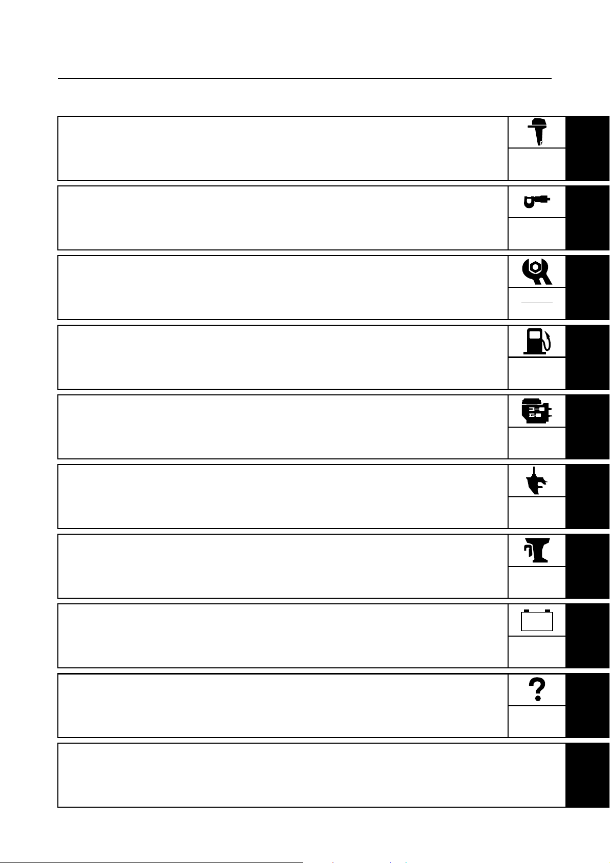
Contents
General information
Specifications
Periodic checks and adjustments
Fuel system
Power unit
GEN
INFO
SPEC
CHK
ADJ
FUEL
POWR
1
2
3
4
5
Lower unit
Bracket unit
Electrical systems
Troubleshooting
Index
LOWR
BRKT
–+
ELEC
TRBL
SHTG
6
7
8
9

GEN
INFO
General information
How to use this manual.................................................................................1-1
Manual format............................................................................................1-1
Symbols.....................................................................................................1-2
Safety while working......................................................................................1-3
Fire prevention...........................................................................................1-3
Ventilation..................................................................................................1-3
Self-protection ...........................................................................................1-3
Parts, lubricants, and sealants ..................................................................1-3
Good working practices .............................................................................1-4
Disassembly and assembly .......................................................................1-4
Identification...................................................................................................1-5
Applicable models .....................................................................................1-5
Serial number ............................................................................................1-5
Features and benefits....................................................................................1-6
Crankshaft and cylinder.............................................................................1-6
Balancer ....................................................................................................1-7
Piston and piston ring ................................................................................1-7
Connecting rod ..........................................................................................1-8
Cylinder head cover...................................................................................1-8
Intake system ............................................................................................1-9
Top cowling .............................................................................................1-10
64E type power trim and tilt unit ..............................................................1-11
Cooling system ........................................................................................1-12
Lubrication system...................................................................................1-13
Fuel system .............................................................................................1-15
Rectifier Regulator...................................................................................1-16
Isolator.....................................................................................................1-16
Technical tips ...............................................................................................1-17
Electronic control system.........................................................................1-17
ECM.........................................................................................................1-17
Fail-safe control .......................................................................................1-18
Warning control .......................................................................................1-19
Shift cut control........................................................................................1-20
Over-revolution control ............................................................................1-20
Fuel pump control....................................................................................1-20
Propeller selection.......................................................................................1-21
Propeller size...........................................................................................1-21
Selection..................................................................................................1-21
63P3F11

Predelivery checks ......................................................................................1-22
Checking the fuel system ........................................................................1-22
Checking the gear oil level ......................................................................1-22
Checking the engine oil level...................................................................1-22
Checking the battery................................................................................1-22
Checking the outboard motor mounting height........................................1-23
Checking the remote control cables ........................................................1-23
Checking the steering system .................................................................1-24
Checking the gear shift and throttle operation.........................................1-24
Checking the power trim and tilt system..................................................1-24
Checking the engine start switch and engine stop lanyard switch ..........1-24
Checking the cooling water pilot hole ......................................................1-25
Test run ...................................................................................................1-25
Break-in ...................................................................................................1-25
After test run ............................................................................................1-25
1
2
3
4
5
6
7
8
9
63P3F11
GEN
INFO
General information
How to use this manual
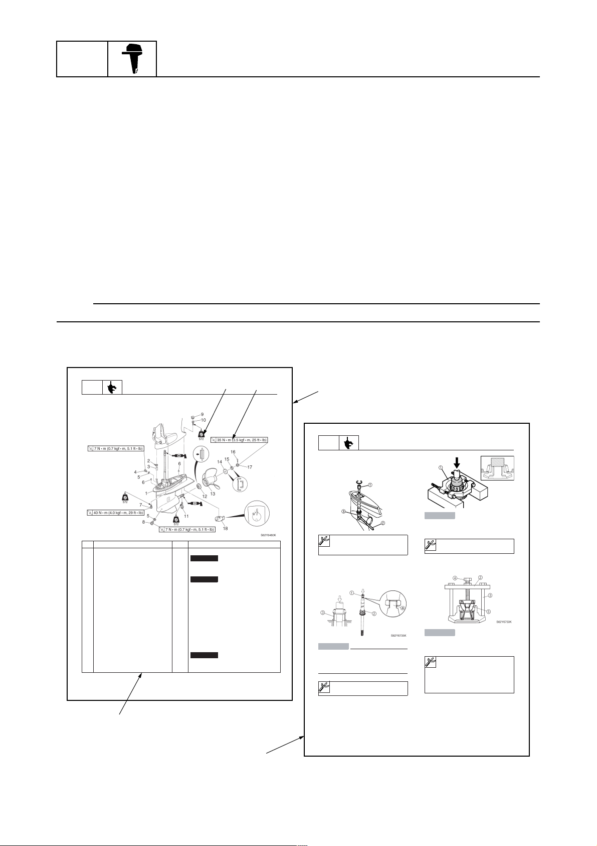
Manual format
The format of this manual has been designed to make service procedures clear and easy to understand. Use the information below as a guide for effective and quality service.
1
Parts are shown and detailed in an exploded diagram and are listed in the components list.
2
Tightening torque specifications are provided in the exploded diagrams and after a numbered
step with tightening instructions.
3
Symbols are used to indicate important aspects of a procedure, such as the grade of lubricant
and lubrication point.
4
The components list consists of part names and part quantities, as well as bolt and screw dimensions.
5
Service points regarding removal, checking, and installation are shown in individual illustrations
to explain the relevant procedure.
NOTE:
For troubleshooting procedures, see Chapter 9, “Troubleshooting.”
1
LOWR
Lower unit
No. Part name Q’ty Remarks
1 Lower unit 1
2 Plastic tie 1
3Hose 1
4 Check screw 1
5 Gasket 2
6 Dowel pin 2
7 Bolt 4 M10 40 mm
8 Drain screw 1
9Grommet 1
10 Bolt 1 M10 45 mm
11 Bolt 1 M8 60 mm
12 Thrust washer 1
13 Propeller 1
14 Washer 1
15 Washer 1
16 Cotter pin 1
17 Propeller nut 1
18 Trim tab 1
6-5
Lower unit
Not reusable
Not reusable
Not reusable
3
4
2
62Y5A11
1
LOWR
Removing the drive shaft
1. Remove the drive shaft assembly and
pinion, and then pull out the forward
gear.
Disassembling the drive shaft
1. Install the pinion nut 1, tighten it finger
tight, and then remove the drive shaft
bearing 2 using a press.
CAUTION:
• Do not press the drive shaft threads
directly.
• Do not reuse the bearing, always
replace it with a new one.
Disassembling the forward gear
1. Remove the taper roller bearing from the
forward gear using a press.
Lower unit
S62Y6850K
Drive shaft holder 4 1: 90890-06518
Pinion nut holder 2: 90890-06505
Socket adapter 2 3: 90890-06507
Bearing inner race attachment 3:
90890-06639
CAUTION:
Do not reuse the bearing, always replace
it with a new one.
Bearing separator 1: 90890-06534
2. Remove the needle bearing from the forward gear.
CAUTION:
Do not reuse the bearing, always replace
it with a new one.
a
Stopper guide plate 2: 90890-06501
Stopper guide stand 3:
90890-06538
Bearing puller 4: 90890-06535
Bearing puller claw 1 5:
90890-06536
S62Y6740K
1-1
5
6-19
62Y5A11
63P3F11
Symbols
T
R
.
.
D
242
LT
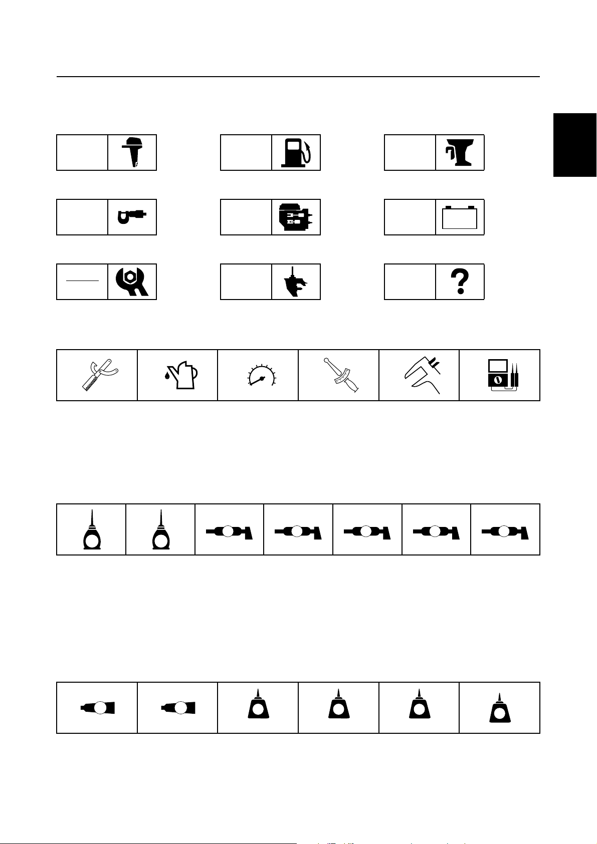
The symbols below are designed to indicate the content of a chapter.
How to use this manual
General information
GEN
INFO
Specifications
SPEC
Periodic checks and adjustments
CHK
ADJ
Symbols 1 to 6 indicate specific data.
123456
Fuel system
FUEL
Power unit
POWR
Lower unit
LOWR
Bracket unit
BRKT
Electrical systems
ELEC
Troubleshooting
– +
TRBL
SHTG
1
2
3
4
Special tool
1
Specified oil or fluid
2
Specified engine speed
3
Specified tightening torque
4
Symbols 7 to C in an exploded diagram indicate the grade of lubricant and the lubrication point.
7890ABC
A M
E G
Apply Yamaha 4-stroke motor oil
7
Apply gear oil
8
Apply water resistant grease (Yamaha grease A)
9
Apply molybdenum disulfide grease
0
Symbols D to I in an exploded diagram indicate the type of sealant or locking agent and the application point.
DEFGHI
GM
4
LT
271
Specified measurement
5
Specified electrical value
6
(resistance, voltage, electric current)
C I
Apply corrosion resistant grease
A
(Yamaha grease D)
Apply low temperature resistant grease
B
(Yamaha grease C)
Apply injector grease
C
LT
572
SS
5
6
7
8
9
Apply Gasket Maker
D
Apply Yamabond No. 4
E
Apply LOCTITE 271 (red)
F
63P3F11
Apply LOCTITE 242 (blue)
G
Apply LOCTITE 572
H
Apply silicon sealant
I
1-2
GEN
INFO
General information
Safety while working
To prevent an accident or injury and to
ensure quality service, follow the safety procedures provided below.
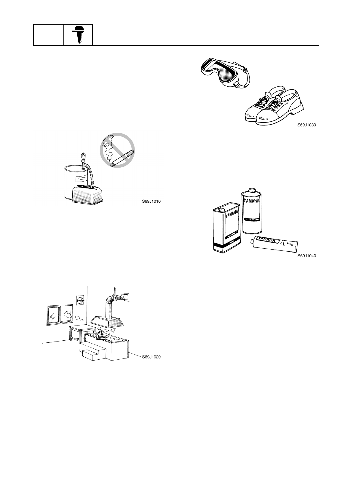
Fire prevention
Gasoline is highly flammable.
Keep gasoline and all flammable products
away from heat, sparks, and open flames.
Ventilation
Gasoline vapor and exhaust gas are heavier
than air and extremely poisonous. If inhaled
in large quantities they may cause loss of
consciousness and death within a short time.
When test running an engine indoors (e.g., in
a water tank) be sure to do so where adequate ventilation can be maintained.
1
Parts, lubricants, and sealants
Use only genuine Yamaha parts, lubricants,
and sealants or those recommended by
Yamaha, when servicing or repairing the outboard motor.
Under normal conditions, the lubricants mentioned in this manual should not harm or be
hazardous to your skin. However, you should
follow these precautions to minimize any risk
when working with lubricants.
Self-protection
Protect your eyes by wearing safety glasses
or safety goggles during all operations involving drilling and grinding, or when using an air
compressor.
Protect your hands and feet by wearing protective gloves and safety shoes when necessary.
1-3
1. Maintain good standards of personal and
industrial hygiene.
2. Change and wash clothing as soon as
possible if soiled with lubricants.
3. Avoid contact with skin. Do not, for
example, place a soiled rag in your
pocket.
4. Wash hands and any other part of the
body thoroughly with soap and hot water
after contact with a lubricant or lubricant
soiled clothing has been made.
5. To protect your skin, apply a protective
cream to your hands before working on
the outboard motor.
63P3F11
Safety while working
6. Keep a supply of clean, lint-free cloths for
wiping up spills, etc.
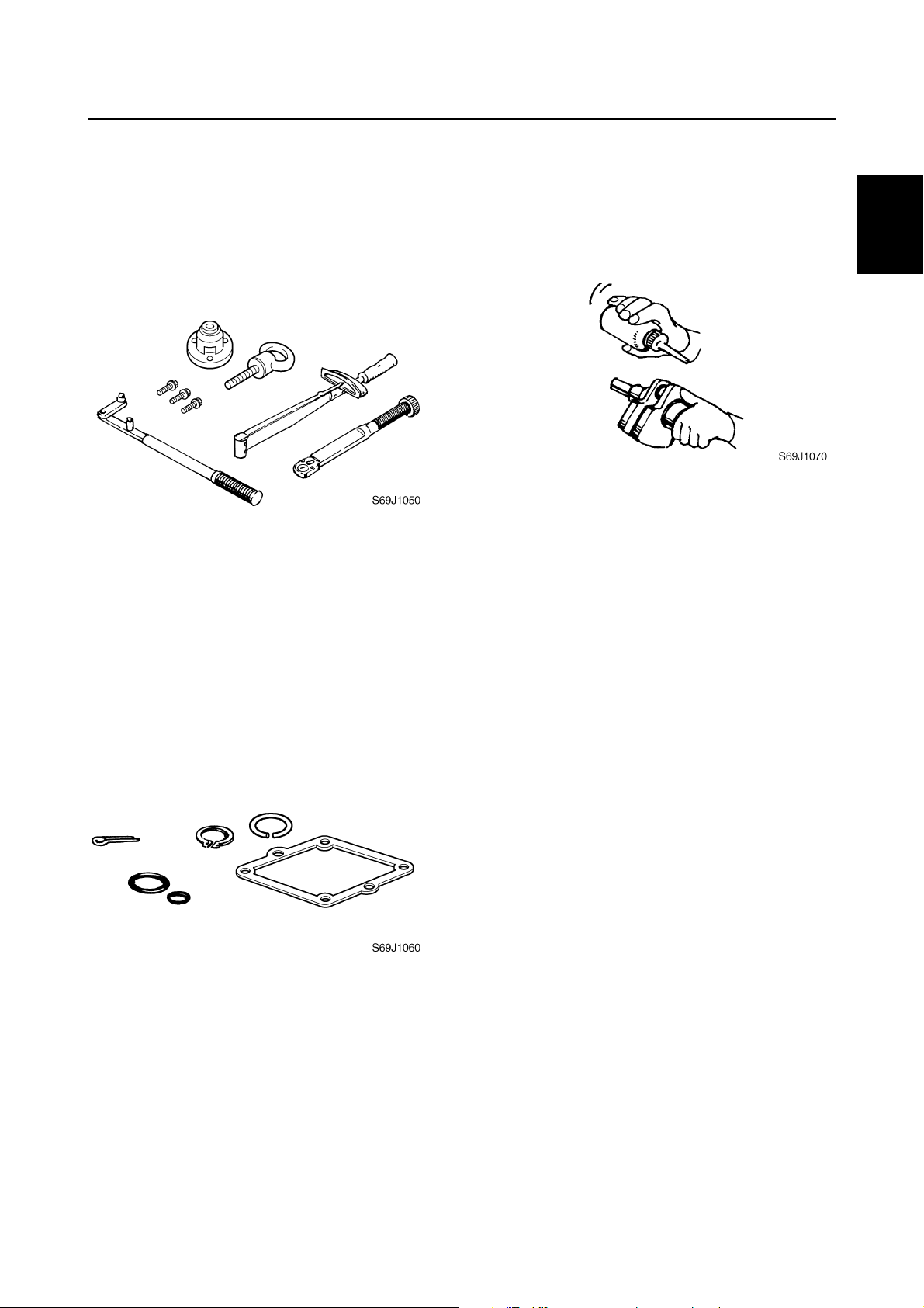
Good working practices
Special service tools
Use the recommended special service tools
to protect parts from damage. Use the right
tool in the right manner—do not improvise.
Tightening torques
Follow the tightening torque specifications
provided throughout the manual. When tightening nuts, bolts, and screws, tighten the
large sizes first, and tighten fasteners starting
in the center and moving outward.
Non-reusable parts
Always use new gaskets, seals, O-rings, cotter pins, circlips, etc., when installing or
assembling parts.
Disassembly and assembly
1. Use compressed air to remove dust and
dirt during disassembly.
2. Apply engine oil to the contact surfaces
of moving parts before assembly.
3. Install bearings with the manufacture
identification mark in the direction indicated in the installation procedure. In
addition, be sure to lubricate the bearings
liberally.
4. Apply a thin coat of water-resistant
grease to the lip and periphery of an oil
seal before installation.
5. Check that moving parts operate normally after assembly.
1
2
3
4
5
6
7
8
9
63P3F11
1-4
GEN
INFO
General information
Identification
Applicable models
This manual covers the following models.
Applicable models
F150AET, FL150AET
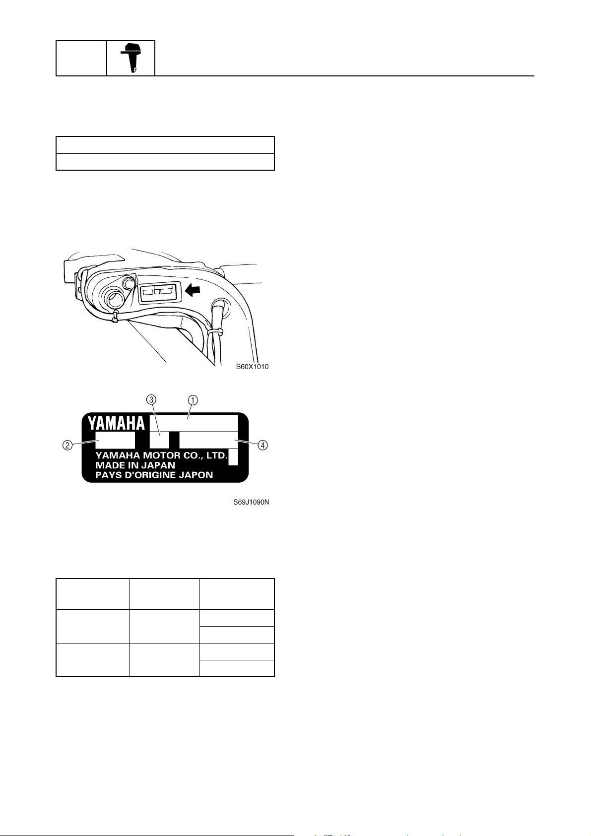
Serial number
The outboard motor serial number is
stamped on a label attached to the port
clamp bracket.
1
Model name
1
Approved model code
2
Transom height
3
Serial number
4
Model name
Approved
model code
F150AET 63P
FL150AET 64P
1-5
Starting
serial No.
L: 1000017–
X: 1000044–
L: 1000013–
X: 1000009–
63P3F11
Identification / Features and benefits
Features and benefits
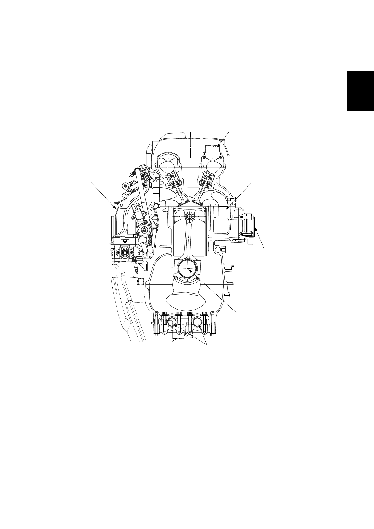
Crankshaft and cylinder
The center of the crankshaft is offset 10 mm (0.39 in) from the center of the cylinder to make more
space to incorporate the throttle body assembly.
This design produces good engine balance and allows a compact design.
Exhaust gas from each cylinder flows directly into the exhaust manifold to obtain a compact design
for the exhaust system.
2
1
3
1
1
2
3
4
Throttle body assembly
1
Oil/gas separator
2
Direct exhaust system
3
Rectifier Regulator
4
Offset 10 mm (0.39 in)
5
Balancer shafts
6
6
5
4
5
6
S63P1070
7
8
63P3F11
9
1-6
GEN
INFO
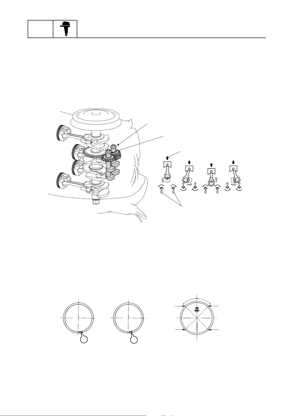
Balancer
A two-piece balancer is used in the crankcase to reduce the secondary forces of inertia produced by
reciprocating pistons.
The balancer shaft 1 is driven by the gear on the crankshaft.
The balancer shaft 2 is driven by the gear on the balancer shaft 1.
The two counterrotating balancer shafts rotate at twice the speed of the crankshaft and reduce the
forces of inertia of the connecting rods and each balancer shaft.
Therefore, engine vibration is reduced.
General information
1
2
3
4
Balancer shaft 1
1
Balancer shaft 2
2
Piston secondary force of inertia
3
Balancer force of inertia
4
Piston and piston ring
A forged piston has been adopted for durability.
Hard chromium plating is applied to the piston rings.
The top and 2nd piston rings differ and are identified by a mark on each ring.
Install the piston rings on the piston with the identification marks facing up.
1
R
2
RN
3
1
4
˚
5
5
4
˚
S63P1080
2
4
S63P1090
Top ring
1
2nd ring
2
Upper oil ring rail
3
Lower oil ring rail
4
1-7
63P3F11

Features and benefits
Connecting rod
A direction mark for installing the connecting rod to the crankshaft in the proper direction is on the
connecting rod cap.
The direction mark should face the flywheel.
The connecting rod and connecting rod cap are manufactured as a single piece. Then, they are split
using impact force. Only use the connecting rods and connecting rod caps in their original combinations, do not interchange them.
1
1
2
S63P1100
Direction mark
1
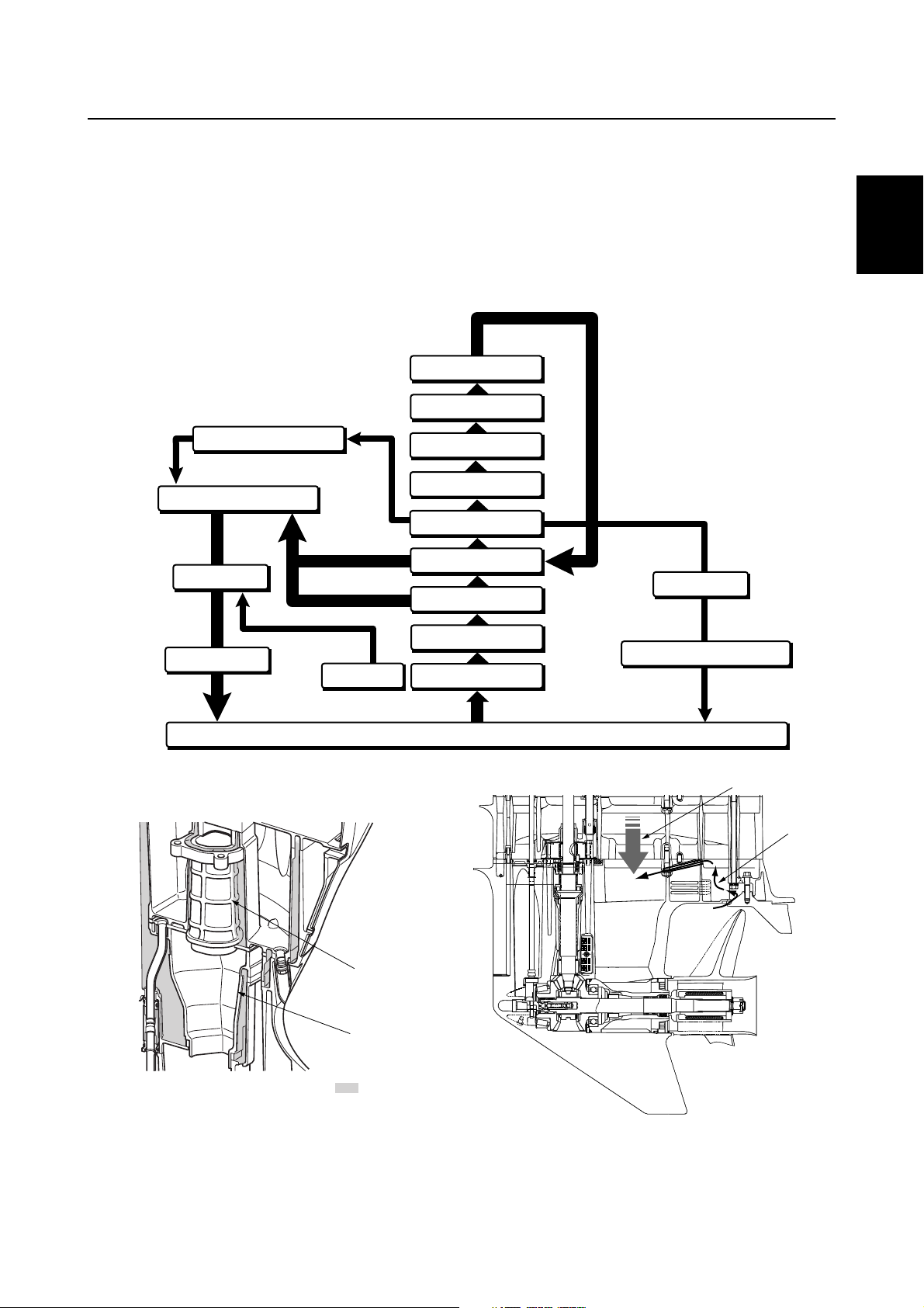
Cylinder head cover
The oil/gas separator is used to obtain low emissions and is built into the cylinder head cover to
obtain a compact design.
The gas and oil flow is shown below.
1
3
4
5
6
7
Intake silencer
1
Cylinder head cover (with gas/oil separator)
2
Blowby gas
È
Oil
É
63P3F11
2
8
:
È
:
É
S63P1110
9
1-8
GEN
INFO
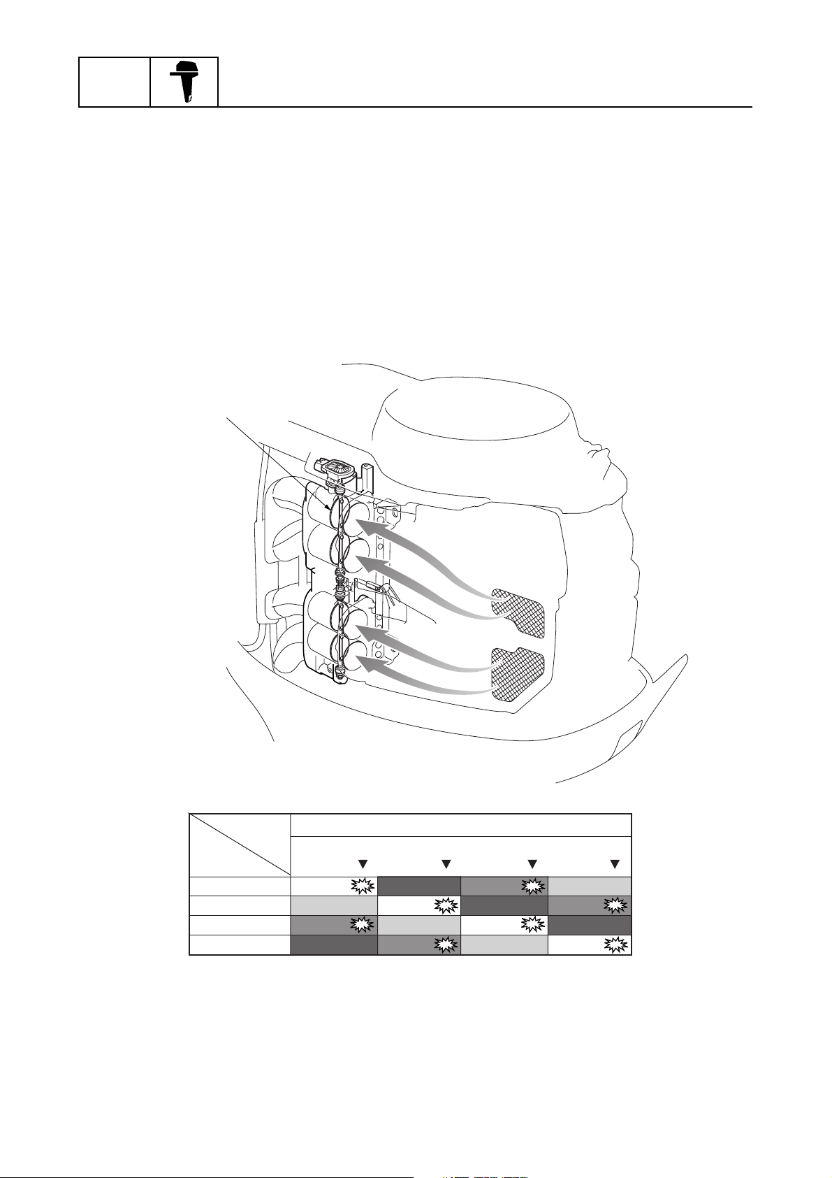
Intake system
Multi-point, group fuel injection with four separate throttle valves is adopted for the intake system.
Intake air volume is calculated according to engine speed, Intake air pressure, and throttle position,
and then the fuel injection volume is determined by the intake air volume to obtain a precise air and
fuel ratio under all operating conditions.
The cylinders are grouped, #1/#4 and #2/#3. Fuel is injected twice during each full cycle of each cylinder, once during the exhaust stroke and once during the compression stroke. Fuel is injected during the compression stroke of the #1 cylinder and the exhaust stroke of the #4 cylinder and during
the exhaust stroke of the #1 cylinder and the compression stroke of the #4 cylinder. The same
occurs during the compression and exhaust strokes of the #2 and #3 cylinders.
This allows a simpler fuel injection control system.
General information
1
#1 cylinder
#3 cylinder
#4 cylinder
#2 cylinder
Four separate throttle valve
1
1-9
Initial injection timing
BTDC10
Compression Combustion
Intake
Exhaust Intake
Combustion
Compression Combustion
Exhaust Intake
Exhaust Intake
Exhaust
Compression Combustion
Compression
S63P1120
63P3F11
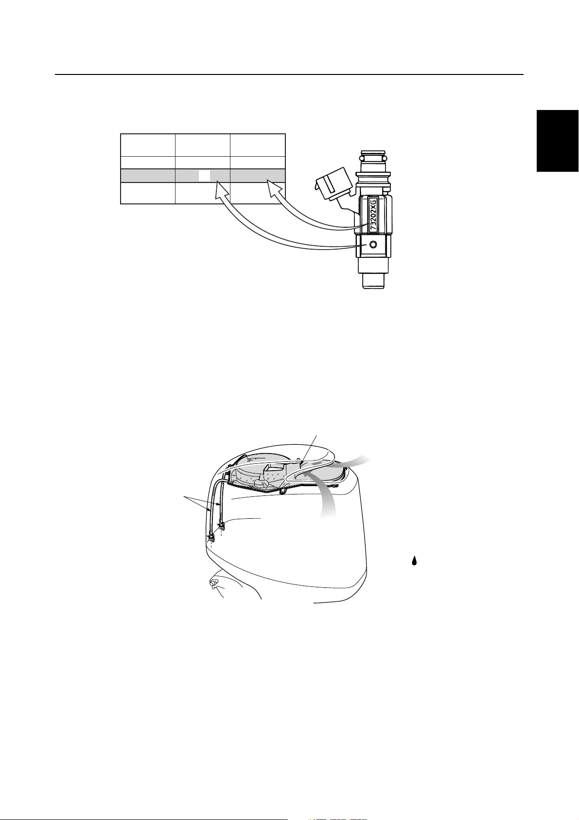
Features and benefits
The shape of the fuel injectors is the same for the F115, F150, F200 and F225.
Therefore, each fuel injector is identified by color because the specifications of each fuel injector are
different.
È
F115 732
F150
F200
F225
Model
È
Injector color
É
First three digits
Ê
Top cowling
Water is separated from the intake air and flows down through the drain hoses before draining out
through the bottom cowling.
The structure of the top cowling helps to prevent water from accumulating in the top cowling and
entering the power unit.
É
Ë
Ì
Í
Ê
731
741
Ë
Ì
Í
1
S63P1130
Orange
Yellow
Ivory
1
2
3
4
5
Water separator
1
Air (including water)
2
Drain hoses
3
Water
È
3
2
6
7
:
È
S63P1140
8
9
63P3F11
1-10
GEN
INFO
64E type power trim and tilt unit
The 64E type clamp bracket and power trim and tilt unit used for current V4 and V6 outboard motors
have been adopted.
This allows easier interchanging of Yamaha outboards with the same classification because the
mounting dimensions are the same.
For the power trim and tilt unit, only the impact absorber valve opening pressure of the tilt piston
fluid circuit has been changed. The pressure is distinguished from those of other models by an identification mark stamped on the power trim and tilt unit.
General information
È
Identification mark Applicable models
YA Carbureted V4 and V6 (2.6)
YB N/A
YC
YD F115 (F115A), LF115 (FL115A), and (F100B)
YE VZ225 (Z225H) and VZ250 (Z250F)
YF F150 (F150A) and LF150 (FL150A)
Electronic fuel injected V6 (2.6), HPDI (2.6),
VX200 (200H), VX225 (225G), and VX250 (250C)
È
S63P1150
1-11
63P3F11
Features and benefits
Cooling system
The cooling water flow diagram is as follows.
To cool the propeller damper, the cooling system is designed so that fresh cooling water is taken in
from the front of the trim tab and supplied to the exhaust passage of the lower case to cool the
exhaust gas.
Cooling water also accumulates around the exhaust muffler to cool the upper case and reduce
exhaust noise.
Thermostat
Cylinder block
1
2
Pressure control valve
Upper case
Lower case
Propeller boss
Trim tab
Cylinder head
Cylinder block
Exhaust cover
Exhaust guide
Oil pan
Water pump
Water inlet
Sea / River / Lake
Fuel cooler
Cooling water pilot hole
3
3
4
5
6
4
7
Exhaust manifold
1
Muffler
2
Exhaust gas
3
63P3F11
1
2
8
:
È
4
È
S63P1170
Water
Water
1-12
9
GEN
INFO
Lubrication system
The lubrication oil flow diagram is as follows.
General information
Balancer
journal
Crankcase
Cylinder sleeve
Piston
Crankpin
Crankshaft main journal
Main passage
Oil filter
Oil filter bracket
Relief valve
Oil pump
Oil strainer
Oil pan
Cylinder head
Camshaft journal
Oil pressure sensor
Camshaft
IN/EX valve
S63P1260
There is a small hole in the relief valve to allow oil to drain from the oil filter bracket so that it does
not remain in the oil filter. This prevents oil from spilling out when replacing the oil filter.
:
È
S63P1180
Relief valve
1
Oil filter bracket
2
Oil
È
1
2
1-13
63P3F11
Features and benefits
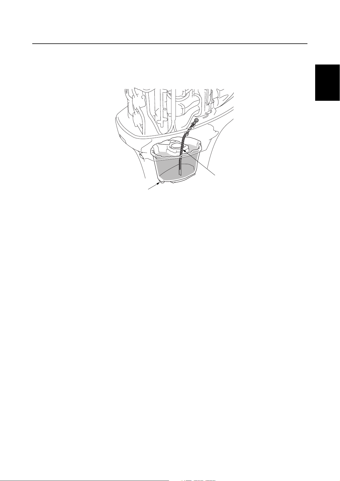
A dual oil drain system is adopted.
An oil drain bolt is located on the bottom of the oil pan.
A long dipstick guide, which reaches the bottom of the oil pan, can also be used to pump out the oil
completely with an oil-extracting tool.
2
1
2
3
Drain bolt
1
Dipstick guide
2
1
S63P1190
4
5
6
7
63P3F11
8
9
1-14
GEN
INFO
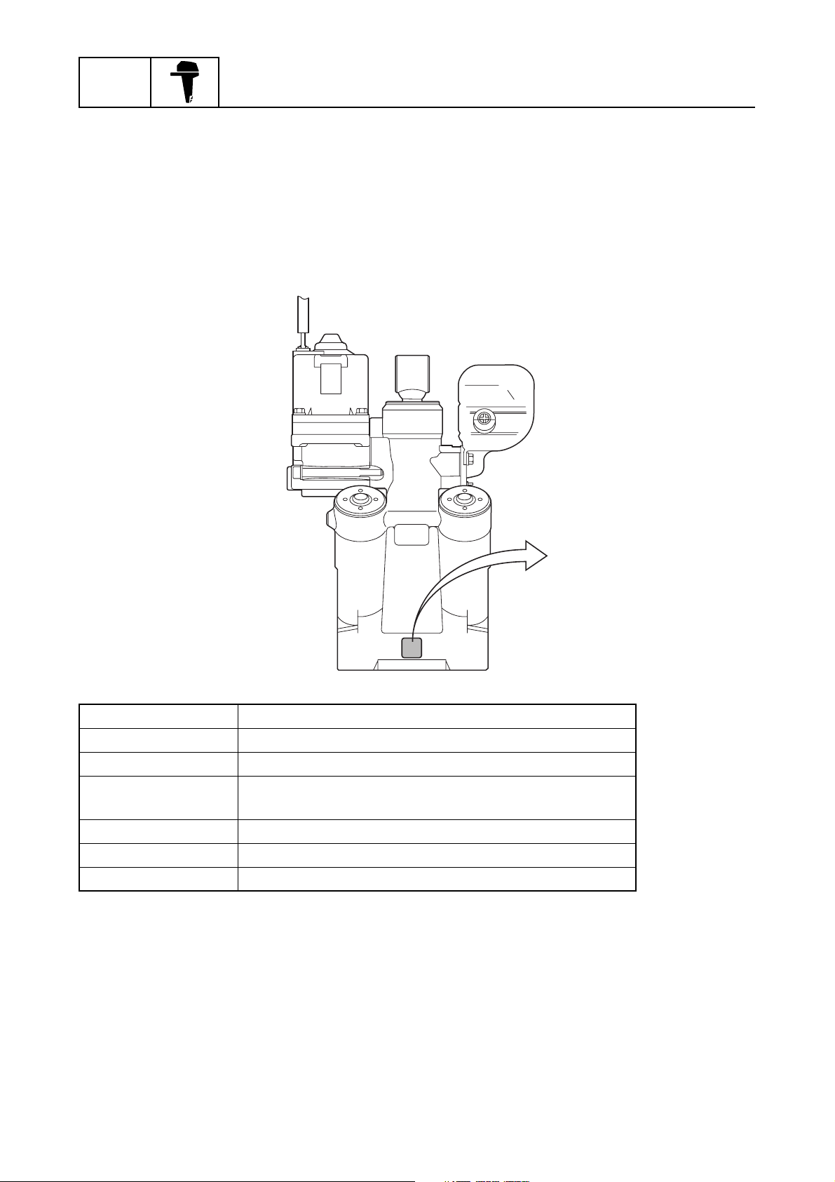
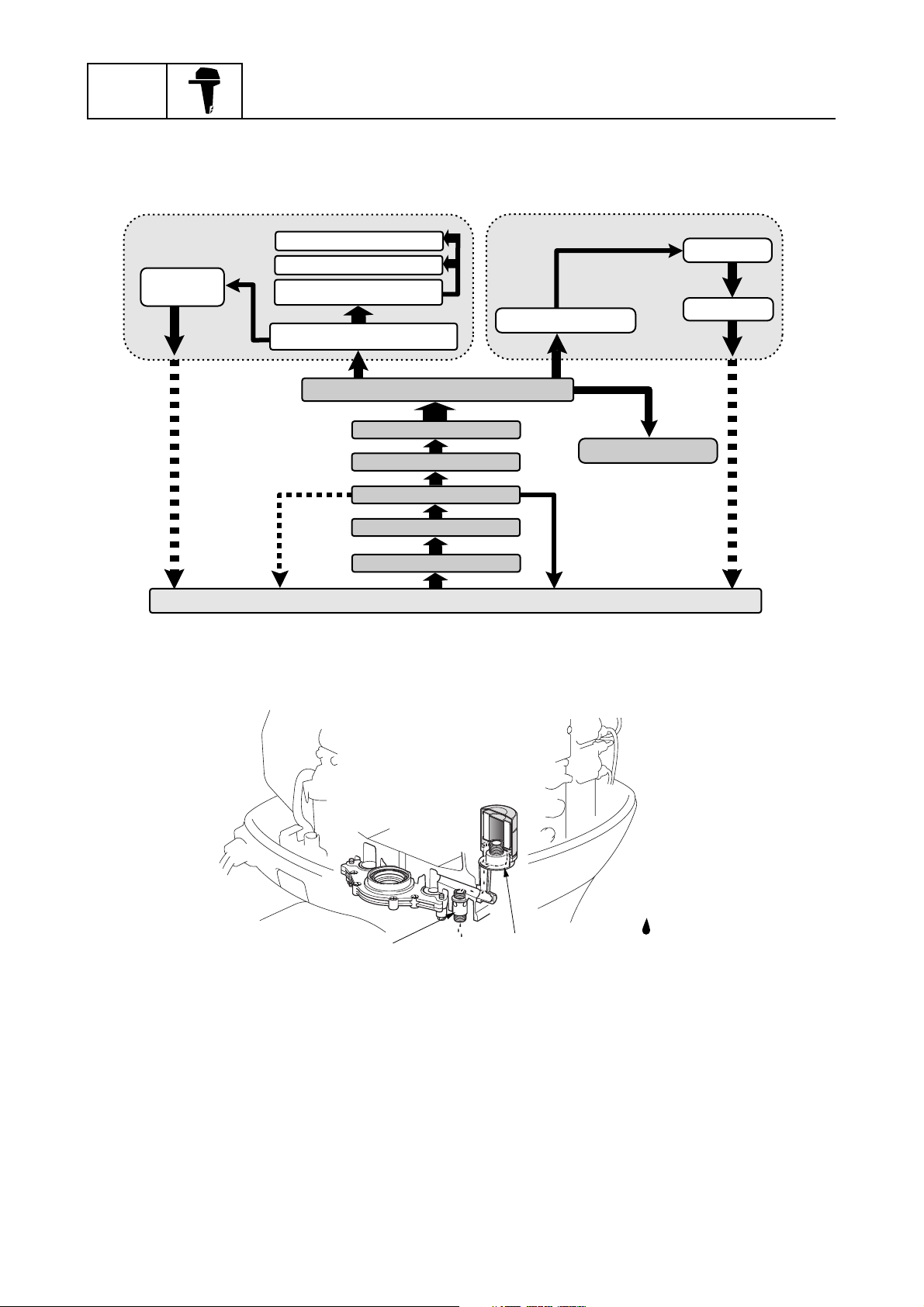
Fuel system
A fuel pressure regulator is incorporated onto the outlet of the electric fuel pump to obtain a compact
design and simple fuel delivery.
Fuel discharged from the pressure regulator returns to the vapor separator after being cooled in the
fuel cooler.
The pressure check valve is incorporated onto the fuel rail for easier servicing of the fuel system.
General information
Fuel tank
Vapor separator Electric fuel pump Fuel rail
Fuel cooler
Fuel filter (fuel tank)
Pressure regulator
Primer pump
Fuel
injector
12
Fuel filter
(69J type)
Fuel
injector
Fuel
injector
3
1
Fuel pump
check valve
Fuel
injector
4
Pressure
Pressure regulator
1
Vapor separator
2
Fuel cooler
3
Fuel flow
È
1-15
3
2
:
È
S63P1200
63P3F11
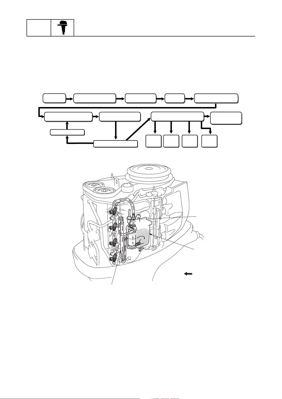
Features and benefits
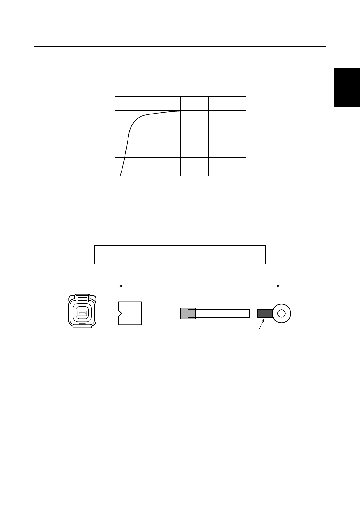
Rectifier Regulator
A water-cooled Rectifier Regulator is incorporated onto the exhaust outer cover.
This allows for a compact engine design and produces a large electric current output for charging
the battery under low engine speed.
40
35
30
25
È
20
15
10
5
0
1,000
Charging current (A)
È
Engine speed (r/min)
É
Isolator
An isolator is incorporated into the Rectifier Regulator. If a second battery is used, connect an
optional isolator lead.
Isolator lead P/N: 69J-81949-00 (3.8 m/12.5 ft)
2,000
3,000
68F-81949-00 (2.7 m/9 ft)
É
4,000
5,000
6,000
7,000
S63P1210
1
2
3
4
5
Red tube
1
3.8 m (12.5 ft)/2.7 m (9 ft)
1
6
S63P1220
7
8
9
63P3F11
1-16
GEN
INFO
General information
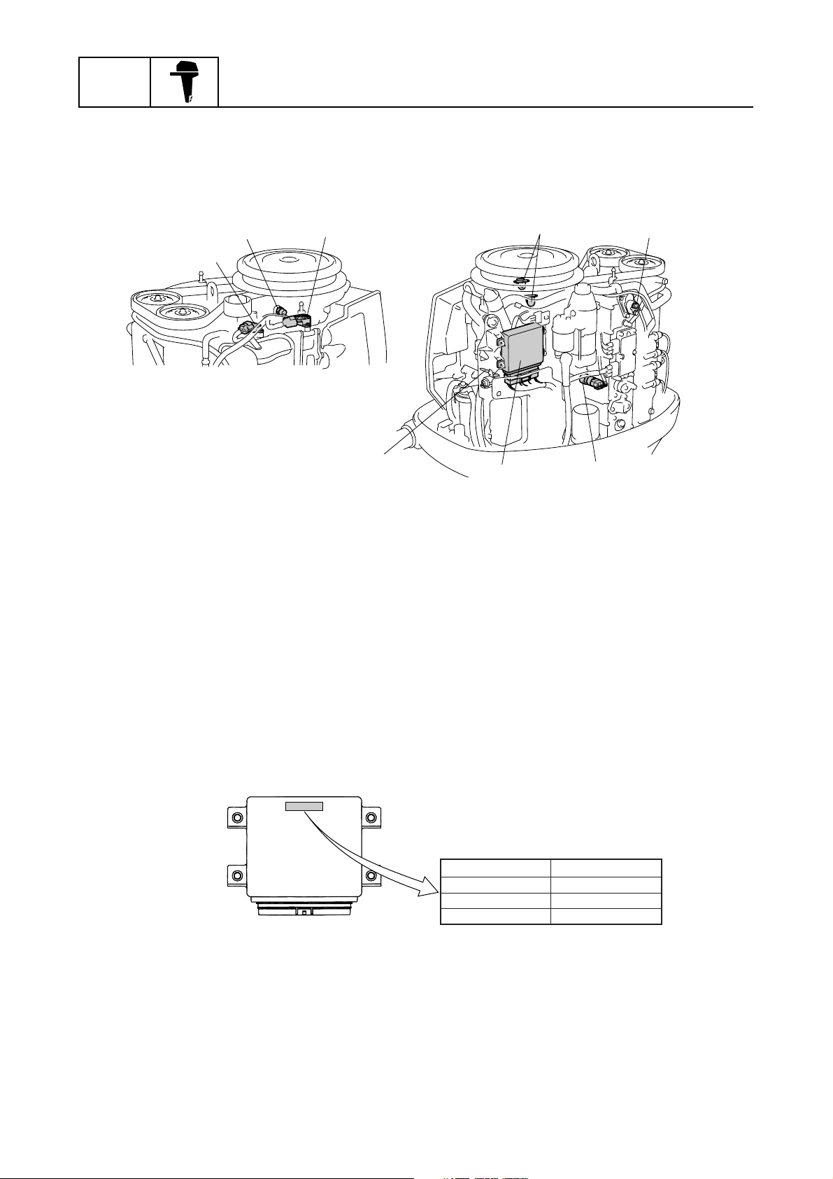
Technical tips
Electronic control system
The electronic control system consists of the sensors and the ECM (electronic control module).
Under various conditions, the ECM provides the best suitable engine operation.
7
4
8
5
S63P1230
1
Intake air pressure sensor
1
Engine temperature sensor
2
Throttle position sensor
3
Pulser coil
4
2
3
6
Thermoswitch
5
Intake air temperature sensor
6
ECM
7
Oil pressure sensor
8
1
ECM
This engine is controlled by the ECM to obtain precise combustion under various operating conditions for high power output, low fuel consumption, and low emissions.
The ECM controls the ignition timing, the fuel injection timing, and the fuel injection volume and
ensures that optimum ignition timing and an optimum air and fuel ratio can be achieved under all
operating conditions such as starting the engine, normal operation, and quick acceleration.
The self-diagnostic function is incorporated into the ECM, and can quickly detect a malfunction
when a personal computer is used with the optional software installed. (Refer to the “Yamaha Diagnostic System Instruction Manual”.)
ÈÉ
63P-00 EUR
63P-10 USA, CAN, OCE
ECM identification
È
Destination
É
63P-20 JPN
S63P1240
1-17
63P3F11

Technical tips
Fail-safe control
If the electrical components malfunction, the ECM controls the ignition and fuel injection as shown in
the table.
Malfunctioning item Details Ignition control Fuel control
No signal received during
Pulser coil
Throttle position
sensor
Intake air pressure
sensor
Engine temperature
sensor
Intake air temperature sensor
Neutral switch
four consecutive crankshaft
rotations
Output voltage is 0.3 V or
lower or 4.7 V or higher
Output voltage is 0.2 V or
lower or 4.5 V or higher
Output voltage is 0.18 V or
lower or 4.93 V or higher
Output voltage is 0.10 V or
lower or 4.61 V or higher
Switch is off when starting
the outboard motor
Fixed to BTDC 10° Fixed to BTDC 10°
Controlled according to the basic
injection map
Normal control
Normal control Normal control
Normal control Normal control
Normal control Normal control
Controlled by Intake
air pressure and
engine speed
Fuel injection volume is controlled by
the throttle position
sensor
1
2
3
4
The switch is on when the
engine temperature is 40 °C
Thermoswitch
Shift cut switch
Oil pressure sensor
During fail-safe control, the engine idle speed increases to 900 r/min except if the neutral switch is
off when the outboard motor is started.
(104 °F) or lower or the
switch is off when the engine
temperature is 130 °C
(266 °F) or higher.
Output voltage is 4.50 V or
higher, the switch is on when
the outboard motor is
started, or both the shift cut
switch and neutral switch are
on for 5 seconds
Output voltage is 0.3 V or
lower or 4.8 V or higher
Normal control Normal control
Normal control Normal control
Normal control Normal control
5
6
7
8
63P3F11
9
1-18

GEN
INFO
Warning control
This outboard motor is equipped with warning control functions to avoid serious engine damage.
The engine speed is limited to approximately 2,000 r/min if the engine overheats, if the oil pressure
is low, or if a dual engine system (DES) is operated.
When a switch turns on, the engine speed is controlled as shown in the table.
General information
Thermo-
switch
On
Overheat warning
indicator lights and
buzzer sounds
Fuel injection is shut off in the cylinder order #1, #4, and #3 at 2.5-second intervals when the engine
is running at 2,000 r/min or more.
Fuel injection to the #2 cylinder is not shut off.
When the throttle-opening angle is 30 degrees or less, fuel injection to the #3 cylinder will begin
again.
When the engine speed decreases to less than 2,000 r/min, fuel injection will begin again in the cylinder order #3, #4, and #1 at 0.2-second intervals.
The warning control mode deactivates when the engine speed is less than 1,600 r/min or the throttle-opening angle is less than 7 degrees.
Engine
temperature
sensor
130 °C
(266 °F) or
higher
(0.63 V or
lower)
Oil pressure
sensor
Below
specified oil
pressure due
to engine
speed
Oil pressure
warning
indicator lights
and buzzer
sounds
DES
signal
On
Buzzer
sounds
Less than
2,000 r/min
Fuel injection
begins again in the
cylinder order #3,
#4, and #1
NOTE:
• The warning indicators light for 3 seconds after the engine start switch is
turned on.
• The buzzer sounds if the lanyard is
removed from the engine stop lanyard
switch while starting the outboard
motor.
Engine speed
2,000 r/min
or more
Fuel injection is
shut off in the
cylinder order #1,
#4, and #3.
1-19
63P3F11

Technical tips
Shift cut control
This outboard motor is equipped with a shift cut control system for easier shifting.
This device misfires and retards the ignition of some cylinders to fluctuate the engine speed
instantly when the engine is running from 400 to 2,000 r/min. This allows smooth engagement
and/or disengagement of the dog clutch.
When shifting, the ignition is shut off as shown in the table.
Engine speed
(r/min)
Shift cut
switch
Off N/A N/A N/A N/A
On N/A
N/A: No misfire control
Over-revolution control
This outboard motor is equipped with an over-revolution control system to protect the engine.
If the engine speed exceeds 6,200 r/min, the fuel injection is shut off as shown in the table below.
less than 400 400 to 729 730 to 2,000 2,001 or more
Misfires the #1
Retards ignition
timing
and #4 cylinders,
and then retards
ignition timing
N/A
1
2
3
4
Engine speed (r/min) Injected cylinder Note
6,199 or less #1, #2, #3, and #4 Normal operation
6,200 to 6,300 #2 and #3
Over-revolution control mode6,301 to 6,550 #2
6,551 or more None
Fuel pump control
The electric fuel pump operates for 3 seconds after the engine start switch is turned on and continues to operate while the engine is running.
The electric fuel pump stops 1 second after the engine is stopped.
NOTE:
After the engine start switch is turned on, all of the fuel injectors are driven to prevent them from
sticking before the electric fuel pump is driven.
5
6
7
8
63P3F11
9
1-20
GEN
INFO
General information
Propeller selection
The performance of a boat and outboard
motor will be critically affected by the size
and type of propeller you choose. Propellers
greatly affect boat speed, acceleration,
engine life, fuel economy, and even boating
and steering capabilities. An incorrect choice
could adversely affect performance and
could also seriously damage the engine.
Use the following information as a guide for
selecting a propeller that meets the operating
conditions of the boat and the outboard
motor.
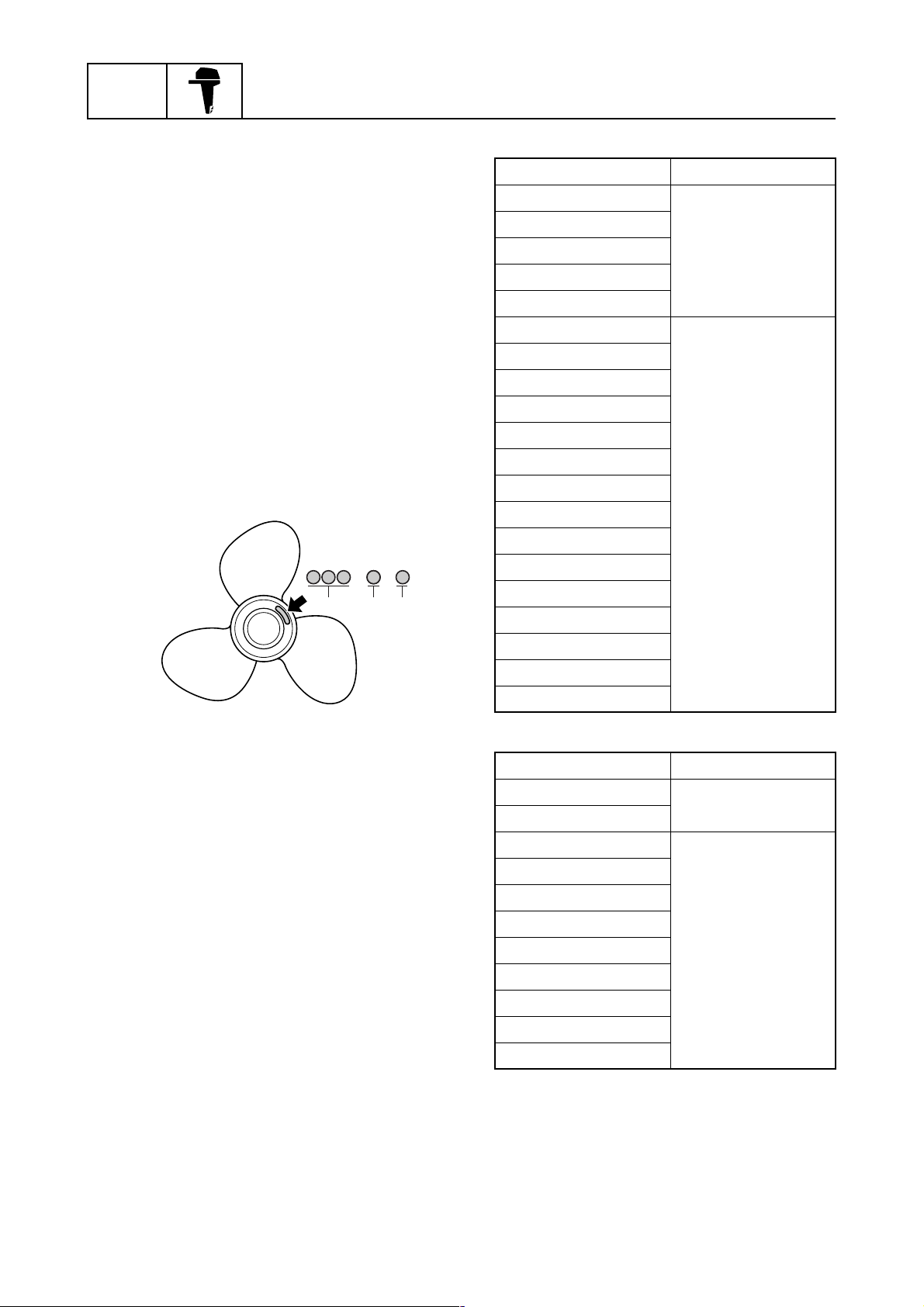
Propeller size
The size of the propeller is indicated on the
propeller boss end.
× -
abc
1
Regular rotation model
Propeller size (in) Material
13 1/2 × 23 - M
13 3/4 × 21 - M
14 × 19 - M
Aluminum
14 1/2 × 17 - M
15 1/4 × 15 - M
13 3/8 × 23 - M
13 3/8 × 25 - M
13 3/4 × 17 - M2
13 3/4 × 19 - M2
13 3/4 × 21 - M
14 1/2 × 15 - M
14 1/2 × 21 - M
14 1/2 × 23 - M
Stainless
14 1/2 × 25 - M
14 1/2 × 27 - M
14 7/8 × 21 - M
15 × 19 - M
15 1/4 × 15 - M
S69J1100
Propeller diameter (in inches)
a
Propeller pitch (in inches)
b
Propeller type (propeller mark)
c
Selection
When the engine speed is at the full throttle
operating range (5,000–6,000 r/min), the
ideal propeller for the boat is one that provides maximum performance in relation to
boat speed and fuel consumption.
15 1/4 × 17 - M
15 3/4 × 13 - M
Counter rotation model
Propeller size (in) Material
14 × 19 - ML
Aluminum
14 1/2 × 17 - ML
13 3/8 × 23 - ML
13 3/4 × 17 - ML1
13 3/4 × 19 - ML1
13 3/4 × 21 - ML
14 1/2 × 23 - ML
Stainless
14 7/8 × 21 - ML
15 1/4 × 15 - ML
15 1/4 × 17 - ML
15 1/4 × 19 - ML
1-21
63P3F11

Propeller selection / Predelivery checks
Predelivery checks
To make the delivery process smooth and
efficient, the predelivery checks should be
completed as explained below.
Checking the fuel system
1. Check that the fuel hoses are securely
connected and that the fuel tank is full
with fuel.
1
Checking the engine oil level
1. Check the engine oil level.
1
2
NOTE:
• If the engine oil is above the maximum level
mark (H), extract sufficient oil with an oil
changer or drain it until the level is between
(H) and (L).
• If the engine oil is below the minimum level
mark (L), add sufficient oil until the level is
between (H) and (L).
3
4
CAUTION:
This is a 4-stroke engine. Never use premixed fuel.
Checking the gear oil level
1. Check the gear oil level.
Recommended engine oil:
4-stroke motor oil
API: SE, SF, SG, SH, or SJ
SAE: 10W-30 or 10W-40
Oil capacity:
Without oil filter replacement:
5.2 L (5.5 US qt, 4.6 Imp qt)
Checking the battery
1. Check the capacity, electrolyte level, and
specified gravity of the battery.
Recommended battery capacity:
CCA/EN: 711 A
20HR/IEC: 100 Ah
Electrolyte specified gravity:
1.280 at 20 °C (68 °F)
2. Check that the positive and negative bat-
tery leads are securely connected.
5
6
7
8
63P3F11
S60V1290
9
1-22
GEN
INFO
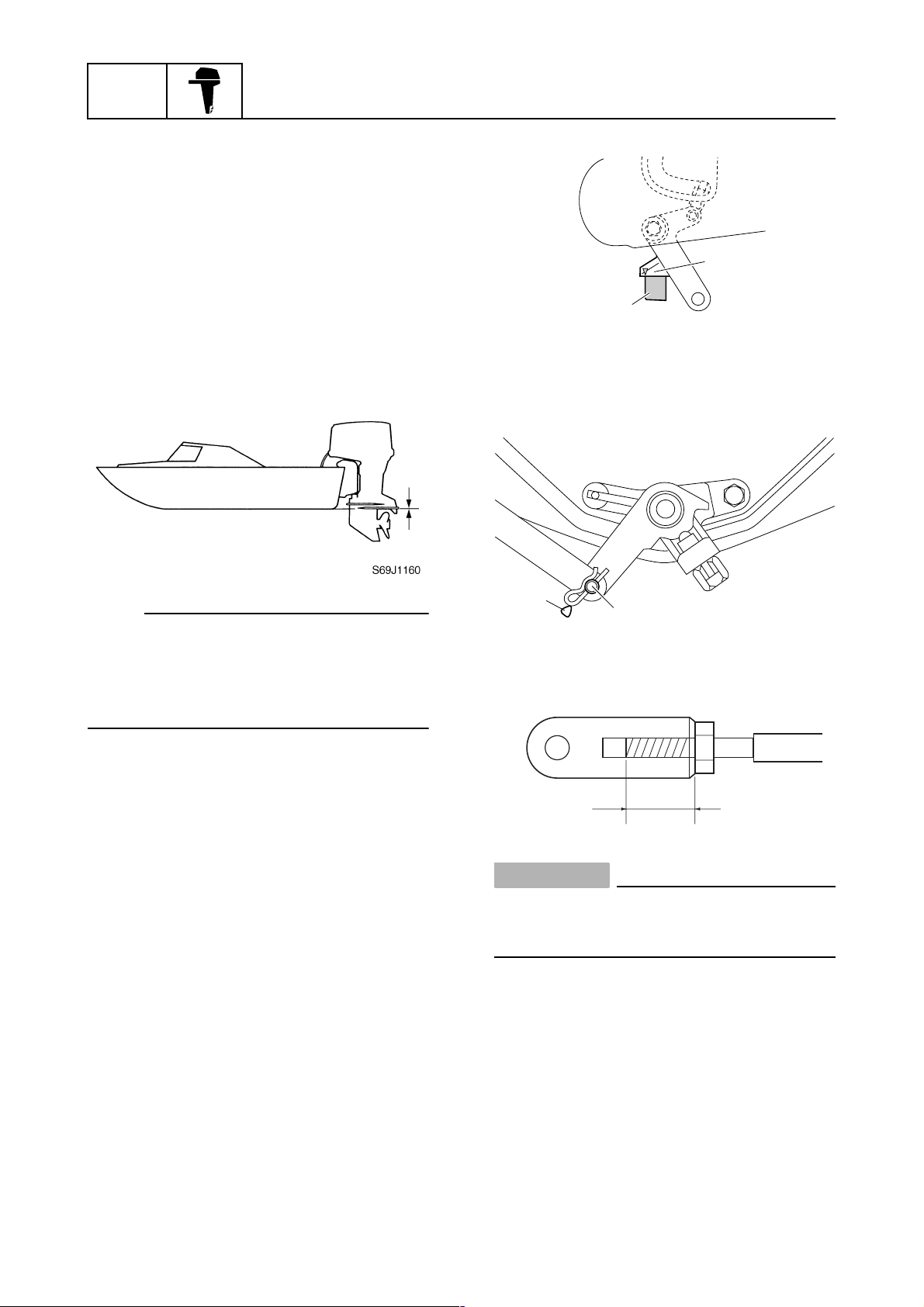
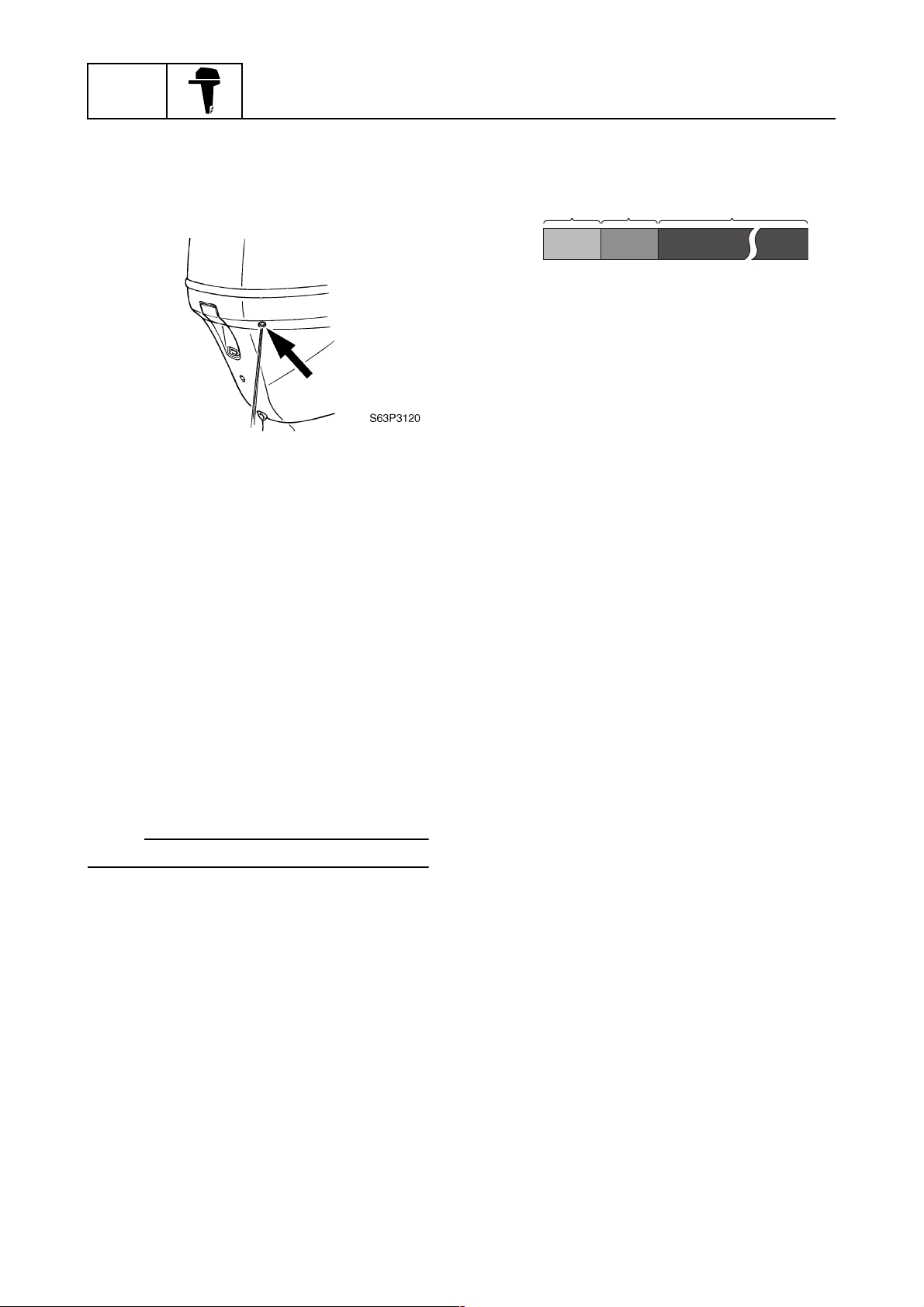
Checking the outboard motor
mounting height
1. Check that the anti-cavitation plate is
aligned with the bottom of the boat. If the
mounting height is too high, cavitation
will occur and propulsion will be reduced.
Also, the engine speed will increase
abnormally and cause the engine to
overheat. If the mounting height is too
low, water resistance will increase and
reduce engine efficiency.
General information
1
2
S63P1040
3. Check that the center of the set pin a is
aligned with the alignment mark b on
the bottom cowling.
NOTE:
The optimum mounting height is affected by
the combination of the boat and the outboard
motor. To determine the optimum mounting
height, test run the outboard motor at different heights.
2. Check that the clamp brackets are
secured with the clamp bolts.
Checking the remote control cables
1. Set the remote control lever to the neutral position and fully close the throttle
lever.
2. Check that the stopper 1 on the throttle
lever 2 contacts the fully closed stopper
2
on the cylinder block.
b
a
c
S63P3270
S69J3370
CAUTION:
The shift/throttle cable joint must be
screwed in a minimum of 8.0 mm (0.31 in)
c
.
1-23
63P3F11
Predelivery checks
Checking the steering system
1. Check the steering friction for proper
adjustment.
2. Check that the steering operates
smoothly.
3. Check that there is no interference with
wires or hoses when the outboard motor
is steered.
Checking the gear shift and throttle
operation
1. Check that the gear shift operates
smoothly when the remote control lever
is shifted from neutral to forward or
reverse.
Checking the power trim and tilt
system
1. Check that the outboard motor tilts up
and down smoothly when operating the
power trim and tilt unit.
2. Check that there is no abnormal noise
produced when the outboard motor is
tilted up or down.
3. Check that there is no interference with
wires or hoses when the tilted-up outboard motor is steered.
4. Check that the trim meter points down
when the outboard motor is tilted all the
way down.
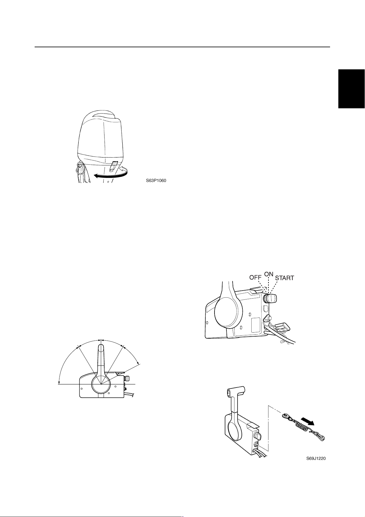
Checking the engine start switch and
engine stop lanyard switch
1. Check that the engine starts when the
engine start switch is turned to START.
2. Check that the engine turns off when the
engine start switch is turned to OFF.
1
2
3
4
5
2. Check that the throttle operates smoothly
when the remote control lever is shifted
from forward or reverse to the fully open
position a.
N
F
a
R
a
S69J1210
6
S60V1070
7
3. Check that the engine turns off when the
engine stop lanyard is pulled from the
engine stop lanyard switch.
8
9
63P3F11
1-24
GEN
INFO
Checking the cooling water pilot
hole
1. Check that cooling water is discharged
from the cooling water pilot hole.
General information
È
È
Hour
ab
0
1
210
c
After test run
1. Check for water in the gear oil.
S69J1240
Test run
1. Start the engine, and then check that the
gear shift operates smoothly.
2. Check the engine idle speed after the
engine has been warmed up.
3. Operate at trolling speed.
4. Run the outboard motor for 1 hour at
2,000 r/min or at half throttle, then for
another hour at 3,000 r/min or at 3/4
throttle.
5. Check that the outboard motor does not
tilt up when shifting into reverse and that
water does not flow in over the transom.
NOTE:
The test run is part of the break-in operation.
2. Check for fuel leakage in the cowling.
3. Flush the cooling water passage with
fresh water using the flushing kit and with
the engine running at idle.
Break-in
During the test run, perform the break-in
operation in the following three stages.
1. One hour a at 2,000 r/min or at approximately half throttle
2. One hour b at 3,000 r/min or 3/4 throttle
and 1 minute out of every 10 at full throttle
3. Eight hours c at any speed, however,
avoid running at full speed for more than
5 minutes
1-25
63P3F11
 Loading...