

Page 1

DSP-AX620
Natural Sound AV Amplifier
Amplificateur audio-vidéo
G B
OWNER’S MANUAL
MODE D’EMPLOI
BEDIENUNGSANLEITUNG
BRUKSANVISNING
MANUALE DI ISTRUZIONI
MANUAL DE INSTRUCCIONES
GEBRUIKSAANWIJZING
Page 2

CAUTION: READ THIS BEFORE OPERATING YOUR UNIT.
1 To assure the finest performance, please read this
manual carefully. Keep it in a safe place for future
reference.
2 Install this unit in a well ventilated, cool, dry, clean
place with at least 30 cm on the top, 20 cm on the
right and left, and 10 cm at the back of this unit for
ventilation space — away from direct sunlight, heat
sources, vibration, dust, moisture, and/or cold.
3 Locate this unit away from other electrical
appliances, motors, or transformers to avoid
humming sounds. To prevent fire or electrical
shock, do not place this unit where it may get
exposed to rain, water, and/or any type of liquid.
4 Do not expose this unit to sudden temperature
changes from cold to hot, and do not locate this
unit in a environment with high humidity (i.e. a room
with a humidifier) to prevent condensation inside
this unit, which may cause an electrical shock, fire,
damage to this unit, and/or personal injury.
5 On the top of this unit, do not place:
– Other components, as they may cause damage
and/or discoloration on the surface of this unit.
– Burning objects (i.e. candles), as they may cause
fire, damage to this unit, and/or personal injury.
– Containers with liquid in them, as they may
cause electrical shock to the user and/or
damage to this unit.
6 Do not cover this unit with a newspaper, tablecloth,
curtain, etc. in order not to obstruct heat radiation.
If the temperature inside this unit rises, it may
cause fire, damage to this unit, and/or personal
injury.
7 Do not plug in this unit to a wall outlet until all
connections are complete.
8 Do not operate this unit upside-down. It may
overheat, possibly causing damage.
9 Do not use force on switches, knobs and/or cords.
10 When disconnecting the power cord from the wall
outlet, grasp the plug; do not pull the cord.
11 Do not clean this unit with chemical solvents; this
might damage the finish. Use a clean, dry cloth.
12 Only voltage specified on this unit must be used.
Using this unit with a higher voltage than specified
is dangerous and may cause fire, damage to this
unit, and/or personal injury. YAMAHA will not be
held responsible for any damage resulting from use
of this unit with a voltage other than specified.
13 To prevent damage by lightning, disconnect the
power cord from the wall outlet during an electrical
storm.
14 Take care of this unit so that no foreign objects and/
or liquid drops inside this unit.
15 Do not attempt to modify or fix this unit. Contact
qualified YAMAHA service personnel when any
service is needed. The cabinet should never be
opened for any reasons.
16 When not planning to use this unit for long periods
of time (i.e. vacation), disconnect the AC power plug
from the wall outlet.
17 Be sure to read the “TROUBLESHOOTING” section
on common operating errors before concluding that
this unit is faulty.
18 Before moving this unit, press STANDBY/ON to set
this unit in the standby mode, and disconnect the
AC power plug from the wall outlet.
19 VOLTAGE SELECTOR (China and General models
only)
The VOLTAGE SELECTOR on the rear panel of this
unit must be set for your local main voltage
BEFORE plugging into the AC main supply.
Voltages are 110/120/220/240 V AC, 50/60 Hz.
This unit is not disconnected from the AC power
source as long as it is connected to the wall outlet,
even if this unit itself is turned off. This state is called
the standby mode. In this state, this unit is designed to
consume a very small quantity of power.
■ For U.K. customers
If the socket outlets in the home are not suitable for the
plug supplied with this appliance, it should be cut off and
an appropriate 3 pin plug fitted. For details, refer to the
instructions described below.
Note
• The plug severed from the mains lead must be destroyed, as a
plug with bared flexible cord is hazardous if engaged in a live
socket outlet.
■ Special Instructions for U.K.
Model
IMPORTANT
THE WIRES IN MAINS LEAD ARE COLOURED
IN ACCORDANCE WITH THE FOLLOWING
CODE:
Blue: NEUTRAL
Brown: LIVE
As the colours of the wires in the mains lead of this
apparatus may not correspond with the coloured
markings identifying the terminals in your plug,
proceed as follows:
The wire which is coloured BLUE must be connected
to the terminal which is marked with the letter N or
coloured BLACK. The wire which is coloured
BROWN must be connected to the terminal which is
marked with the letter L or coloured RED.
Making sure that neither core is connected to the earth
terminal of the three pin plug.
II
CAUTION
II
Page 3

INTRODUCTION
CONTENTS
INTRODUCTION
FEATURES ............................................................ 2
GETTING STARTED ........................................... 3
Checking the Package Contents ............................... 3
Installing Batteries in the Remote Control ............... 3
CONTROLS AND FUNCTIONS ........................ 4
Front Panel ............................................................... 4
Remote Control ........................................................ 6
Description of the Numeric Buttons ........................ 7
Using the Remote Control ........................................ 8
Front Panel Display .................................................. 9
Rear Panel .............................................................. 10
PREPARATION
SPEAKER SETUP .............................................. 11
Speakers to Be Used ............................................... 11
Speaker Placement ................................................. 11
CONNECTIONS ................................................. 12
Before Connecting Components ............................ 12
Connecting Audio Components ............................. 12
Connecting Video Components .............................. 14
Connecting the Speakers ........................................ 16
Connecting an External Amplifier (Europe and U.K.
models only) ....................................................... 18
Connecting an External Decoder ........................... 18
IMPEDANCE SELECTOR Switch ....................... 19
Connecting the Power Supply Cords ..................... 19
ON-SCREEN DISPLAY (OSD) ......................... 20
OSD Modes ............................................................ 20
Selecting the OSD Mode ........................................ 20
SPEAKER MODE SETTINGS ......................... 21
Summary of SPEAKER SET Items
1A through 1E .................................................... 21
ADJUSTING THE SPEAKER
OUTPUT LEVELS ......................................... 22
Before You Begin ................................................... 22
Using the Test Tone (TEST DOLBY SUR.) .......... 22
BASIC OPERATION
BASIC PLAYBACK ........................................... 24
Input Modes and Indications .................................. 26
Selecting a Sound Field Program ........................... 28
Normal Stereo Reproduction .................................. 29
BASIC RECORDING ......................................... 30
ADVANCED OPERATION
SET MENU .......................................................... 31
Adjusting the Items on the SET MENU ................. 31
1 SPEAKER SET (speaker mode settings) ........... 32
2 L/R BALANCE (balance of the left and
right main speakers) ........................................... 34
3 HP TONE CTRL (headphone tone control) ....... 35
4 I/O ASSIGNMENT ............................................ 35
5 INPUT MODE (initial input mode) ................... 35
6 DOLBY D. SET (Dolby Digital set) .................. 36
7 DTS SET (DTS LFE level) ................................ 36
8 SP DELAY TIME............................................... 37
9 DISPLAY SET ................................................... 37
10MEMORY GUARD ........................................... 37
ADJUSTING THE LEVEL OF THE EFFECT
SPEAKERS ...................................................... 38
SLEEP TIMER .................................................... 39
Setting the Sleep Timer .......................................... 39
Canceling the Sleep Timer ..................................... 39
REMOTE CONTROL FEATURES .................. 40
Selector Dial ........................................................... 40
Commonly Used Buttons in Any Position of the
Selector Dial ....................................................... 41
Controlling the Components Connected
to This Unit ........................................................ 41
Button Names and Functions in Each Position ...... 42
Setting the Manufacturer Code .............................. 45
Returning to the Factory Setting ............................ 46
ADDITIONAL INFORMATION
SOUND FIELD PROGRAM ............................. 47
Hi-Fi DSP Programs ............................................... 47
CINEMA DSP Programs ........................................ 47
SOUND FIELD PROGRAM PARAMETER
EDITING ......................................................... 50
What is a sound field? ............................................ 50
Sound Field Program Parameters ........................... 50
Changing Parameter Settings ................................. 51
Resetting a Parameter to the Factory-set Value ...... 51
Sound Field Parameter Descriptions ...................... 52
APPENDIX
TROUBLESHOOTING ..................................... 55
SPECIFICATIONS ............................................. 59
GLOSSARY ......................................................... 60
INDEX .................................................................. 62
INTRODUCTION
PREPARATION
OPERATION
BASIC
OPERATION
ADVANCED
INFORMATION
ADDITIONAL
APPENDIX
1
English
Page 4

FEATURES
Built-in 5-Channel Power Amplifier
◆ Minimum RMS Output Power
(0.06% THD, 20 Hz – 20 kHz)
Main: 90 W + 90 W (8 Ω)
Center: 90 W (8 Ω)
Rear: 90 W + 90 W (8 Ω)
◆ Maximum Power (EIAJ)
[China and General models only]
(10% THD, 1 kHz)
Main: 115 W + 115 W (8 Ω)
Center: 115 W (8 Ω)
Rear: 115 W + 115 W (8 Ω)
Multi-Mode Digital Sound Field
Processing
◆ DTS Decoder
◆ Dolby Pro Logic Decoder
◆ Dolby Digital Decoder
◆ Hi-Fi DSP
◆ CINEMA DSP: Combination of YAMAHA DSP
Technology and Dolby Pro Logic, Dolby Digital
or DTS
◆ Virtual CINEMA DSP
◆ SILENT CINEMA
Other Features
◆ 96-kHz/24-bit D/A Converter
◆ “SET MENU” which Provides You with
10 Items for Optimizing This Unit for Your
Audio/Video System
◆ Test Tone Generator for Easier Speaker Balance
Adjustment
◆ 6-Channel External Decoder Input for Other
Future Formats
◆ BASS EXTENSION Button for Reinforcing
Bass Response
◆ On Screen Display Function Helpful in
Controlling This Unit
◆ S Video Signal Input/Output Capability
◆ Component Video Input/Output Capability
◆ Optical and Coaxial Digital Audio Signal Jacks
◆ Sleep Timer
◆ Remote Control with Preset Manufacturer Codes
• y indicates a tip for your operation.
• Some operations can be performed by using either the buttons on the main unit or on the remote control. In cases
when the button names differ between the main unit and the remote control, the button name on the remote control
is given in parentheses in this manual.
Manufactured under license from Dolby Laboratories.
“Dolby”, “AC-3”, “Pro Logic” and the double-D symbol are
trademarks of Dolby Laboratories.
Confidential Unpublished Works. ©1992-1997 Dolby
Laboratories, Inc. All rights reserved.
Manufactured under license from Digital Theater Systems, Inc.
US Pat. No. 5,451,942 and other world-wide patents issued and
pending. “DTS” and “DTS Digital Surround” are trademarks of
Digital Theater Systems, Inc. Copyright 1996 Digital Theater
Systems, Inc. All Rights Reserved.
2
Page 5
GETTING STARTED
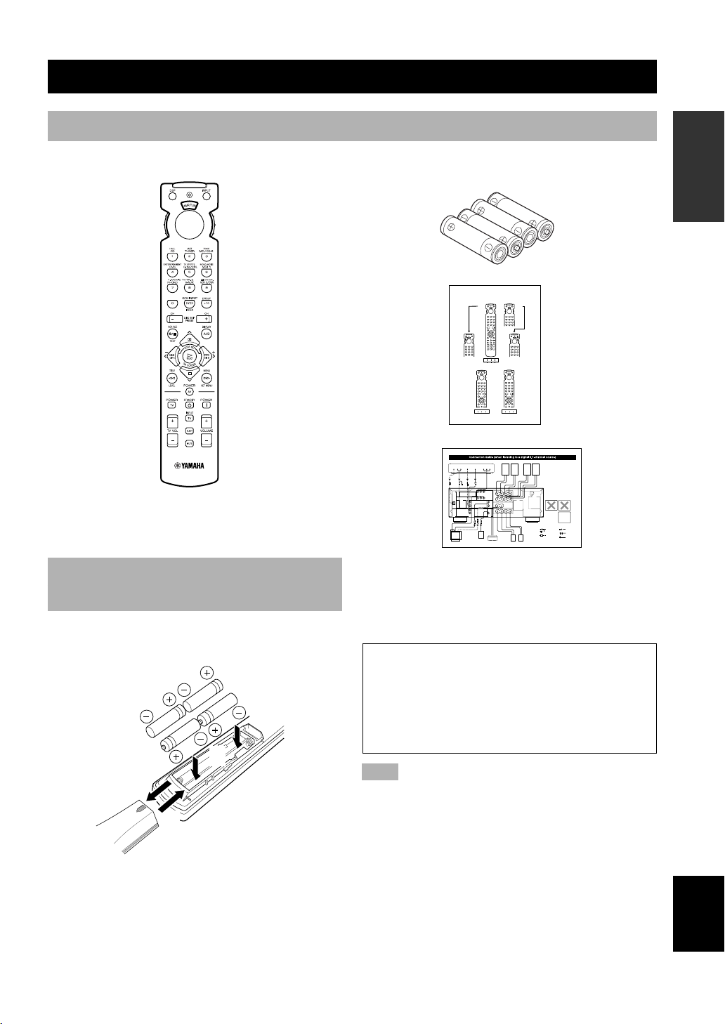
Checking the Package Contents
Check your package to make sure it has the following items.
Remote control
A/B/C/D/E
INTRODUCTION PREPARATION
Batteries (4)
(AAA, R03, UM-4)
Quick Reference Card
Quick Reference Card
OPERAIONT
BASIC
Connection guide
Installing Batteries in the Remote Control
Insert the batteries in the correct direction by aligning the
+ and – marks on the batteries with the polarity markings
(+ and –) inside the battery compartment.
2
1
3
■ Notes on batteries
• Change the batteries periodically.
• Do not use old batteries together with new ones.
• Do not use different types of batteries (such as alkaline
and manganese batteries) together. Read the packaging
carefully as these different types of batteries may have
the same shape and color.
■ Changing batteries
As the batteries lose power, the operating range of the
remote control decreases and the indicator does not flash
or its light becomes dim. When you notice any of these
conditions, change all of the batteries.
If the remote control is without batteries for more than
2 minutes, or if exhausted batteries remain in the
remote control, the contents of the memory may be
cleared. When the memory is cleared, insert new
batteries, set up the manufacturer code that may have
been cleared.
Note
• If the batteries have leaked, dispose of them immediately.
Avoid touching the leaked material or letting it come into
contact with clothing, etc. Clean the battery compartment
thoroughly before installing new batteries.
3
OPERATION
ADVANCED
INFORMATION
ADDITIONAL
APPENDIX
English
Page 6
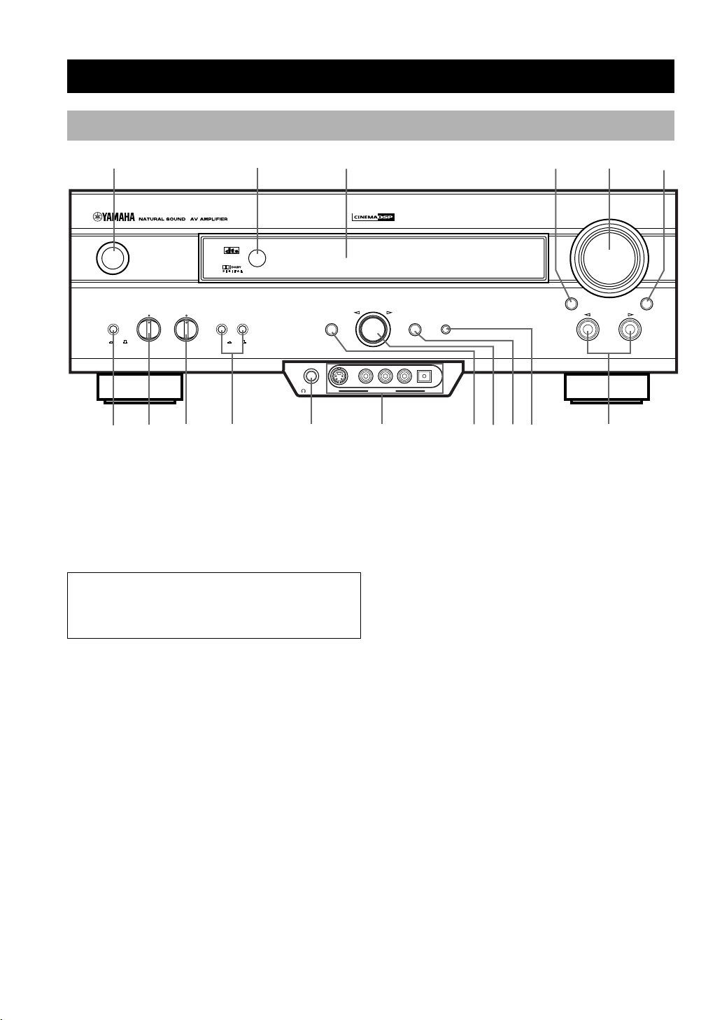
Front Panel
y
CONTROLS AND FUNCTIONS
1
STANDBY
/ON
BASS TREBLE SPEAKERS
BASS
EXTENSION
– + – +
8
7
9 0
2
DIGITAL
SURROUND
AB
ONOFFON
OFF
3 4
PHONES S VIDEO VIDEO L AUDIO R OPTICAL
SILENT VIDEO AUX
qw
1 STANDBY/ON
Turns on or sets this unit in the standby mode. When you
turn on this unit, you will hear a click and there will be a
4 to 5-second delay before this unit can reproduce sound.
Standby mode
In this mode, this unit consumes a small amount of
power to receive infrared-signals from the remote
control.
2 Remote control sensor
Receives signals from the remote control.
3 Front panel display
Shows information about the operational status of this
unit.
4 INPUT MODE
Selects the mode of input for sources that send two or
more types of signals to this unit (see page 26 for details).
You cannot control the input mode when you select 6CH
INPUT as the input source.
5
DIGITAL
–+
DSP
PROGRAM
EFFECTSET MENU
e
r
t
VOLUME
INPUT
u
5 VOLUME
Controls the output level of all audio channels.
This does not affect the REC OUT level.
6 6CH INPUT
Selects the source connected to the 6CH INPUT jacks.
The source selected by pressing 6CH INPUT takes
priority over the source selected with INPUT l / h (or
the input selector buttons on the remote control).
7 BASS EXTENSION ON/OFF
When pushed in (ON), this feature boosts the bass
frequency of the left and right main speakers by +6 dB
(60 Hz) while maintaining overall tonal balance. This
boost is useful if you do not use a subwoofer.
However, this boost may not be noticeable if “1B MAIN
SP” on the SET MENU is set to SMALL and “1D LFE/
BASS OUT” is set to SWFR.
6
6CH INPUTINPUT MODE
4
Page 7

CONTROLS AND FUNCTIONS
8 BASS
Adjusts the low-frequency response for the left and right
main speakers.
Turn the control to the right to increase or to the left to
decrease the low-frequency response.
9 TREBLE
Adjusts the high-frequency response for the left and right
main speakers.
Turn the control to the right to increase or to the left to
decrease the high-frequency response.
Note
• If you increase or decrease the high-frequency or the lowfrequency sound to an extreme level, the tonal quality from the
center and rear speakers may not match that of the left and
right main speakers.
0 SPEAKERS A/B
When pushed in (ON), these buttons turn on the set of
main speakers connected to the A and/or B terminals on
the rear panel.
q PHONES jack
Outputs audio signals for private listening with
headphones. When you connect headphones, no signals
are output to the speakers.
y
(Europe and U.K. models only)
• When you connect headphones, no signals are also output to
the OUTPUT jacks.
w VIDEO AUX jacks
Inputs audio and video signals from a portable external
source such as a game console. To reproduce source
signals from these jacks, select V-AUX as the input
source.
e SET MENU
Enters the SET MENU.
r Multi jog knob
Selects and adjust the SET MENU item after pressing
SET MENU.
Selects the DSP program after pressing DSP PROGRAM.
t DSP PROGRAM
Switches the function of the multi jog knob for selecting
DSP program.
y EFFECT
Switches the effect speakers (center and rear) on and off.
If you turn off the output of these speakers by using
EFFECT, all Dolby Digital and DTS audio signals except
for the LFE channel are directed to the main left and right
channels.
When Dolby Digital or DTS signals are mixed, the left
and right main channel signal levels may not match.
u INPUT l / h
Selects the input source (CD, TUNER, MD/CD-R, DVD,
D-TV/CBL, VCR 1, PHONO, V-AUX, VCR 2/DVR) you
want to listen to or watch.
INTRODUCTION PREPARATION
OPERAIONT
BASIC
OPERATION
ADVANCED
5
INFORMATION
ADDITIONAL
APPENDIX
English
Page 8
CONTROLS AND FUNCTIONS
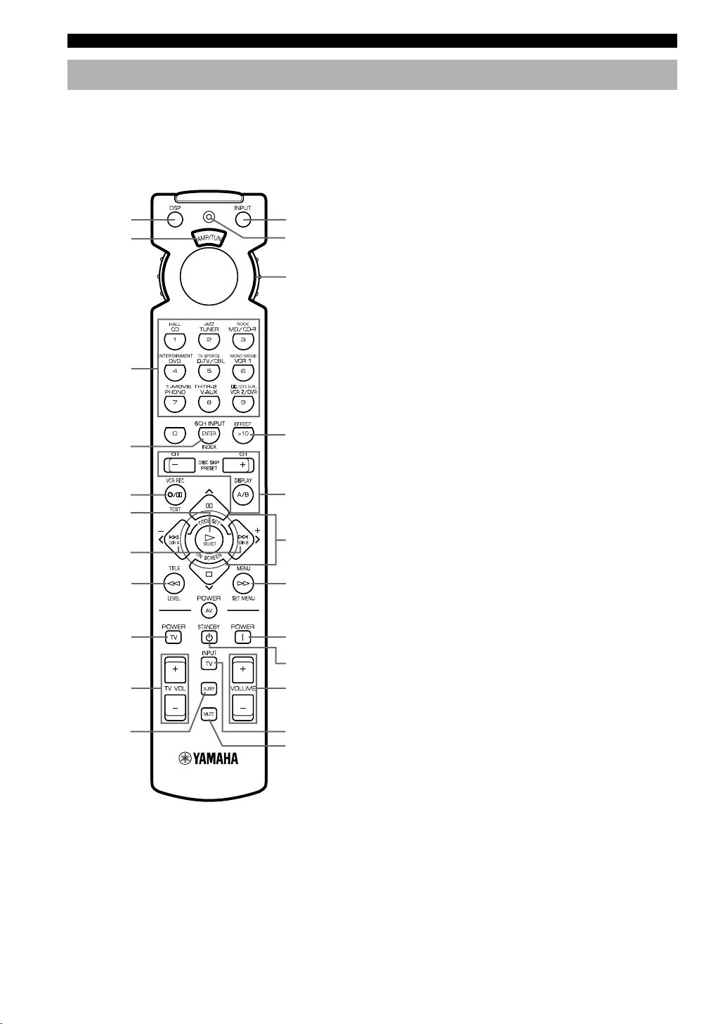
Remote Control
This section describes the basic operation of this unit with
the remote control. First, set the selector dial to the AMP/
TUN position. See “REMOTE CONTROL FEATURES”
for full details.
1
2
Select the
AMP/TUN
position.
0
q
w
3
4
EFFECT
5
6
A/B/C/D/E
e
r
7
8
TV POWER
t
y
u
TV VOLUME
9
i
TV INPUT
o
3 Numeric buttons (Input selector buttons)
These buttons select the input source.
See “Description of the Numeric Buttons” for the
numeric buttons.
4 6CH INPUT
Selects the source connected to the 6CH INPUT jacks.
5 TEST
Outputs the test tone.
6 ON SCREEN
Selects the on-screen display (OSD) mode for your video
monitor.
7 j / i (–/+)
Adjust DSP program parameters and SET MENU items.
–/+ is displayed on the on-screen display.
8 LEVEL
Selects the effect speaker channel (center, rear and
subwoofer) so you can adjust their output level
independently.
9 SLEEP
Sets the sleep timer.
0 INPUT
Switches the function of the numeric buttons to the input
selector.
q Indicator
Flashes while the remote control is sending signals.
w Selector dial
Turn this dial to select the position for the component to
be controlled. (The proper code must be set up for your
component. See “Setting the Manufacture Codes”.) When
a position is selected, the remote control is set to that
component operation mode.
e A/B/C/D/E, PRESET –/+
These buttons are used to select a preset station when
using YAMAHA tuner.
A/B/C/D/E: To select one of 5 preset station groups (A
to E)
PRESET –/+: To select a preset station number (1 to 8)
1 DSP
Switches the function of the numeric buttons to the DSP
program selector.
2 Indicator window
Shows the name of components which can be controlled.
6
r u/d
Select DSP program parameters and SET MENU items.
t SET MENU
Enters the SET MENU.
y POWER
Turns on the power of this unit.
u STANDBY
Sets this unit in the standby mode.
Page 9
CONTROLS AND FUNCTIONS
i VOLUME +/–
Increases or decreases the volume level.
o MUTE
Mutes the sound. Press again to restore the audio output
to the previous volume level.
EFFECT
Switches the effect speakers (center and rear) on and off
in the following cases:
• When the selector dial is set to the DSP/TUN position.
• While the indicator is lit for about 3 seconds after
pressing DSP.
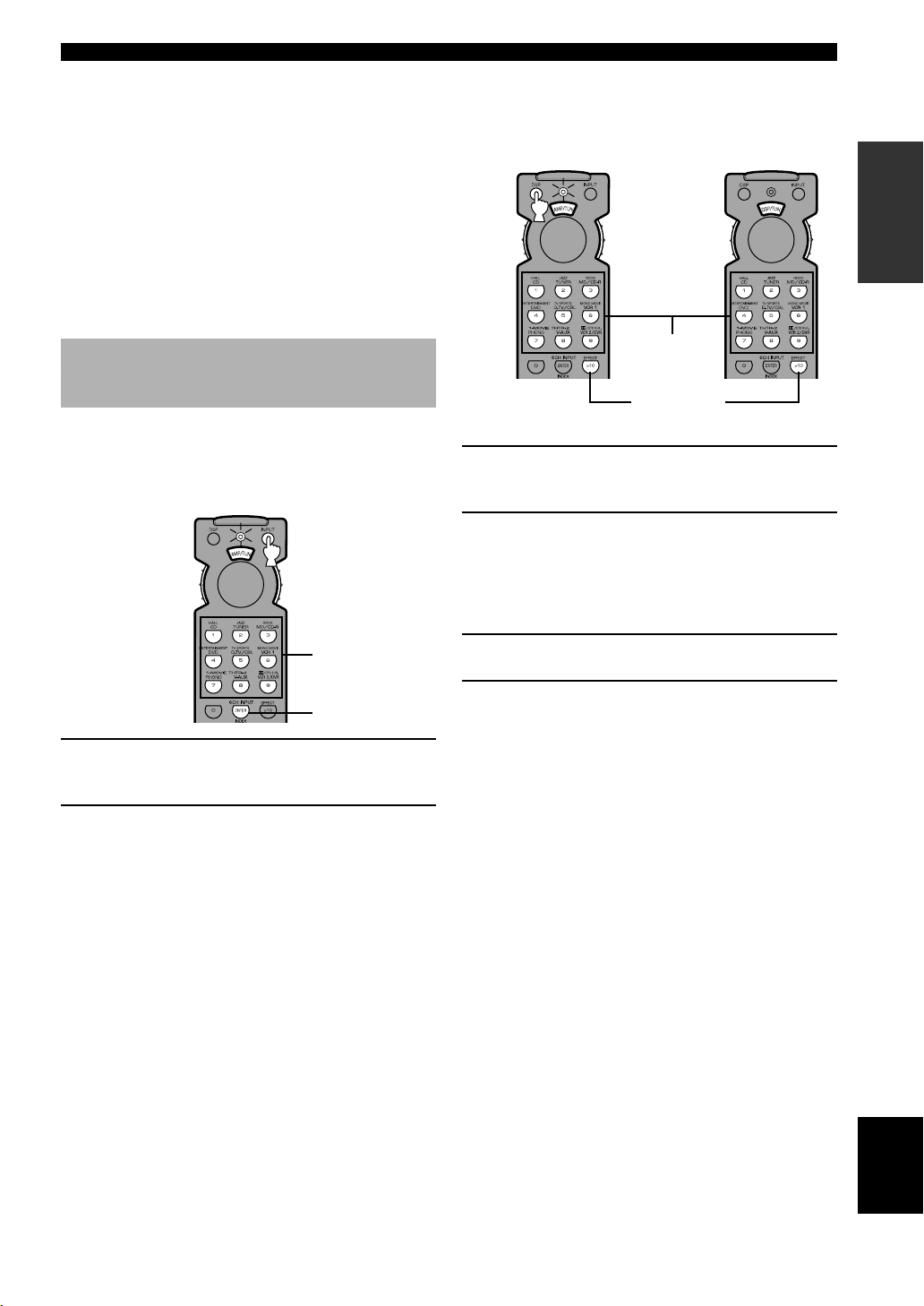
Description of the Numeric Buttons
The numeric buttons function in various ways depending
on the position of the selector dial or the combination of
other instructions.
■ When selecting an input source
■ When selecting a DSP program
and turning on or off the effect
speakers (center and rear)
A
DSP program
group buttons
B
EFFECT
A
1 Press DSP regardless of the position of the
selector dial.
The indicator lights up for about 3 seconds.
2 You can select a DSP program with the
numeric buttons and turn on or off the effect
speakers (center and rear) by pressing
EFFECT while the indicator is lit.
INTRODUCTION PREPARATION
OPERAIONT
BASIC
Input selector
buttons
6CH INPUT
1 Press INPUT regardless of the position of
the selector dial.
The indicator lights up for about 3 seconds.
2 You can select an input source with the
numeric buttons and 6CH INPUT while the
indicator is lit.
B
1 Set the selector dial to the DSP/TUN
position.
2 You can select a DSP program directly with
the numeric buttons and turn on or off the
effect speakers (center and rear) by pressing
EFFECT.
OPERATION
ADVANCED
INFORMATION
ADDITIONAL
APPENDIX
English
7
Page 10
CONTROLS AND FUNCTIONS
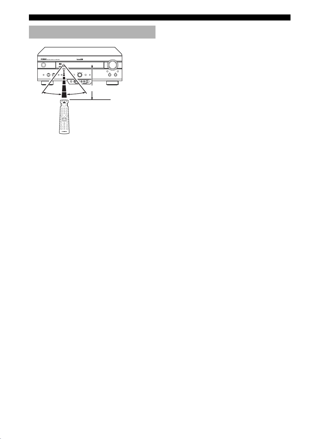
Using the Remote Control
DIGITAL
SURROUND
–+–
+
30° 30°
DIGITAL
Approximately 6 m (20 feet)
The remote control transmits a directional infrared beam.
Be sure to aim the remote control directly at the remote
control sensor on the main unit during operation.
■ Handling the remote control
• Do not spill water or other liquids on the remote
control.
• Do not drop the remote control.
• Do not leave or store the remote control in the
following types of conditions:
– high humidity or temperature such as near a heater,
stove or bath;
– dusty places; or
– in places subject to extremely low temperatures.
8
Page 11

Front Panel Display
1 2
4
3
CONTROLS AND FUNCTIONS
INTRODUCTION PREPARATION
D-TV/CBL
PCM
5
VIRTUAL
DIGITAL
PRO LOGIC
DSP
ASPB
6 7
V-AUX
VCR2/DVR
DOLBY DIGITAL
PRO LOGIC DTS
VCR 1
MOVIE THEATER 1 2
ENTERTAINMENT
8
1 t indicator
Lights up when the built-in DTS decoder is on.
2 VIRTUAL indicator
Lights up when using Virtual CINEMA DSP.
3 g and o indicators
Light up according to the type of Dolby signals this unit
is reproducing. “ g ” lights up when the builtin Dolby Digital decoder is on. “ o ” lights up
when the built-in Dolby Pro Logic decoder is on.
4 Input source indicator
Shows the current input source with a cursor.
5 x indicator
Lights up when you select a DSP program.
6 v indicator
Lights up when this unit is reproducing PCM (pulse code
modulation) digital audio signals.
CDTUNER PHONO
VOLUME
dB
ms
SLEEP
0 q
9
DVD
MD/CD-R
7 Headphones indicator
Lights up when headphones are connected.
8 DSP program indicators
The name of the selected DSP program lights up when
the ENTERTAINMENT, MOVIE THEATER 1, MOVIE
THEATER 2 or q/DTS SURROUND DSP program is
selected.
9 Multi-information display
Shows the current DSP program name and other
information when adjusting or changing settings.
0 VOLUME level indicator
Indicates the volume level.
q SLEEP indicator
Lights up while the sleep timer is on.
OPERAIONT
BASIC
OPERATION
ADVANCED
INFORMATION
ADDITIONAL
APPENDIX
English
9
Page 12
CONTROLS AND FUNCTIONS
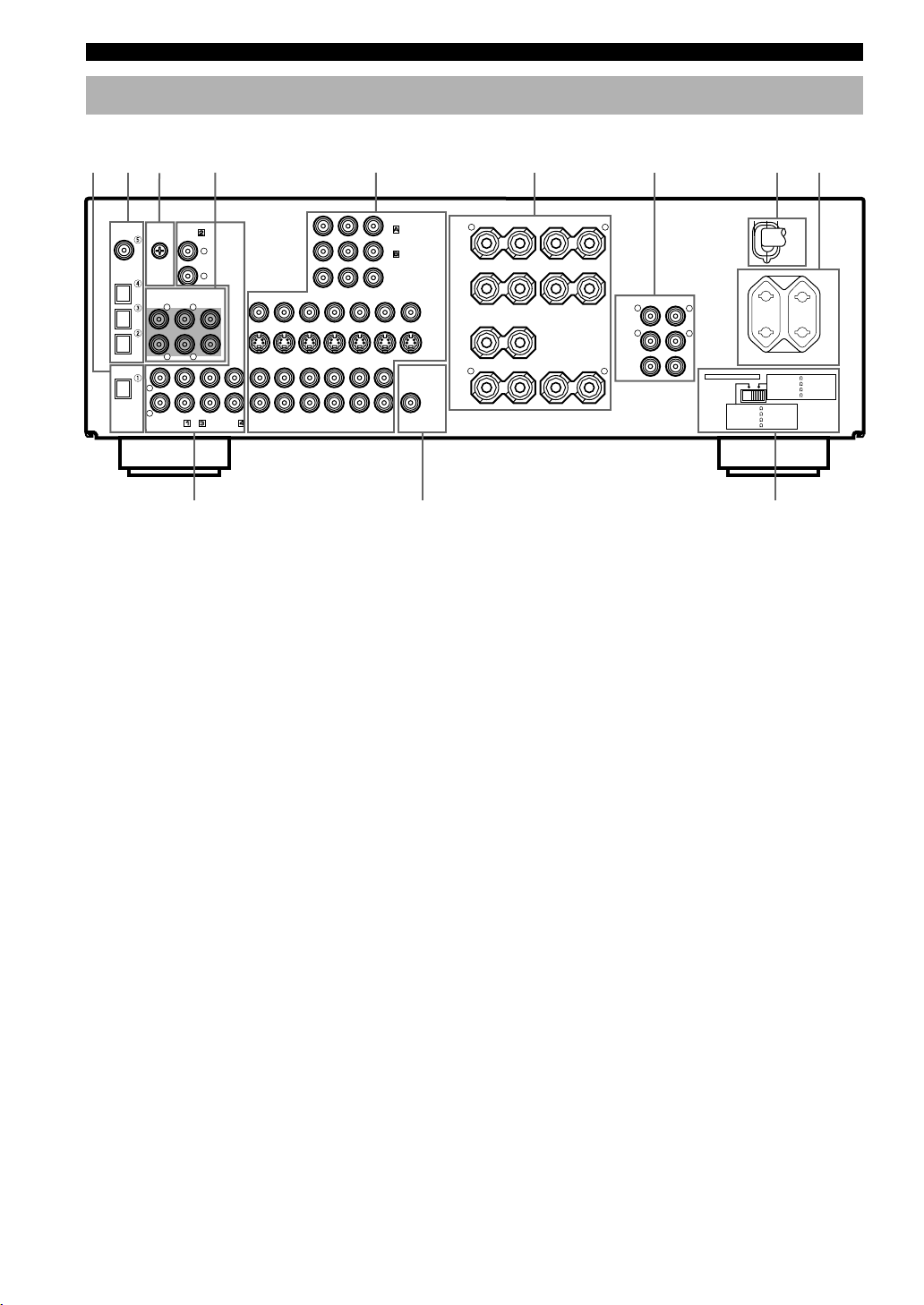
Rear Panel
1 4 5
2
DIGITAL
INPUT
CD
COAXIAL
OPTICAL
D-TV/CBL
DVD
MD/CD-R
OPTICAL
MD/CD-R
DIGITAL
OUTPUT
3
L
R
GND
MAIN
PHONO
TUNER
6CH INPUT
SURROUND
RLR
CD
L
R
CENTER
L
SUB WOOFER
IN(PLAY)
MD/CD-R
OUT(REC)
D-TV/CBL
DVD
DVD
D-TV/CBL
AUDIO SIGNAL
DVD
D-TV/CBL
MONITOR
VCR 2
/DVR
VCR 2/DVR
OUT
OUT
OUT
MONITOR OUT
WOOFER
YPB/CBPR/CRCOMPONENT VIDEO
VCR 1
IN
OUT IN
VIDEO SIGNAL
IN
OUT IN
VCR 1
SUB
VIDEO
S VIDEO
OUTPUT
0 q
1 DIGITAL OUTPUT jacks
2 DIGITAL INPUT jacks
3 GND terminal
See page 12 for connection information.
4 6CH INPUT jacks
See page 18 for connection information.
5 Video component jacks
See pages 14 and 15 for connection information.
6 Speaker terminals
See pages 16 and 17 for connection information.
7 OUTPUT jacks (Europe and U.K. models only)
See page 18 for connection information.
6 7
SPEAKERS
+
–
–
R L
+
8 9
A
MAIN
B
CENTER
R
REAR
(SURROUND)
+
+
–
––
OUTPUT
R
MAIN
REAR
(SURROUND)
CENTER
+
L
L
R
L
IMPEDANCE SELECTOR
SET BEFORE POWER ON
MAIN A OR B: 4
A + B: 8
CENTER
REAR
100W MAX. TOTAL
MAIN A OR B: 8
CENTER
REAR
MIN. /SPEAKER
MIN. /SPEAKER
: 6
MIN. /SPEAKER
: 6
MIN. /SPEAKER
AC OUTLETS
SWITCHED
w
(Europe model)
8 AC power cord
Connect to a power outlet.
9 AC OUTLET(S)
Use these outlets to supply power to your other audio/
video components (see page 19).
0 Audio component jacks
See pages 12 and 13 for connection information.
q SUBWOOFER jack
See page 17 for connection information.
w IMPEDANCE SELECTOR switch
Use this switch to match the amplifier output to your
speaker impedance. Set this unit in the standby mode
before you change the setting of this switch (see page 19).
A + B:16
MAINS
: 8
: 8
MIN. /SPEAKER
MIN. /SPEAKER
MIN. /SPEAKER
MIN. /SPEAKER
10
China and General models only
VOLTAGE SELECTOR
See page 19.
Page 13
PREPARATION
Speakers to Be Used
SPEAKER SETUP
INTRODUCTION
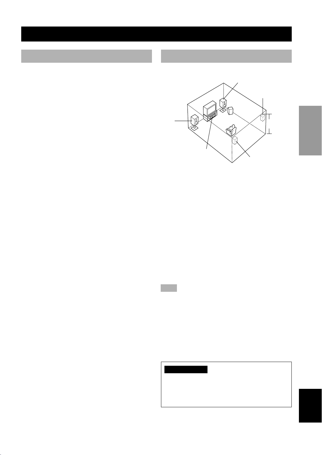
Speaker Placement
This unit has been designed to provide the best soundfield quality with a 5-speaker system, using left and right
main speakers, left and right rear speakers, and a center
speaker. If you use different brands of speakers (with
different tonal qualities) in your system, the tone of a
moving human voice and other types of sound may not
shift smoothly. We recommend that you use speakers
from the same manufacturer to ensure even tonal quality.
The main speakers are used for the main source sound
plus the effect sounds. They will probably be the speakers
from your present stereo system. The rear speakers are
used for the effect and surround sounds, and the center
speaker is for the center sounds (dialog, vocals, etc.). If
for some reason it is not practical to use a center speaker,
you can do without it. Best results, however, are obtained
with the full system.
The main speakers should be high-performance models
and have enough power-handling capacity to accept the
maximum output of your audio system. The other
speakers do not have to be equal to the main speakers.
For precise sound localization, however, it is ideal to use
high-performance models that can reproduce sounds over
the full range for the center speaker and the rear speakers.
■ Use of a subwoofer expands your
sound field
It is also possible to further expand your system with the
addition of a subwoofer. The use of a subwoofer is
effective not only for reinforcing bass frequencies from
any or all channels, but also for reproducing the LFE
(low-frequency effect) channel with high fidelity when
the Dolby Digital signal or the DTS signal is played back.
The YAMAHA Active Servo Processing Subwoofer
System is ideal for natural and lively bass reproduction.
Refer to the following diagram when you place the
speakers.
Main
speaker (L)
Center speaker
Main speaker (R)
Rear speaker (R)
Subwoofer
1.8 m
Rear speaker (L)
■ Main speakers
Place the left and right main speakers an equal distance
from the ideal listening position. The distance of each
speaker from each side of the video monitor should be the
same.
■ Rear speakers
Place these speakers behind your listening position,
facing slightly inwards, nearly 1.8 m (approx. 6 feet)
above the floor.
■ Center speaker
Align the front face of the center speaker with the front
face of your video monitor. Place the speaker as close to
the monitor as possible, such as directly over or under the
monitor and centrally between the main speakers.
Note
• If the center speaker is not used, the center channel sound will
be heard from the left and right main speakers. In this case,
“1A CENTER SP” on the SET MENU is set to NONE.
PREPARATION
BASIC OPERA-
TION
OPERATION
ADVANCED
INFORMATION
ADDITIONAL
■ Subwoofer
The position of the subwoofer is not so critical, because
low bass sounds are not highly directional. But it is better
to place the subwoofer near the main speakers. Turn it
slightly toward the center of the room to reduce the wall
reflections.
CAUTION
Please use magnetically shielded speakers. Sometimes
a video monitor may be adversely affected even when
magnetically shielded speakers are used. Separate the
speakers from the monitor if this happens.
11
APPENDIX
English
Page 14

CONNECTIONS
Before Connecting Components
CAUTION
Never connect this unit and other components to mains power until all connections between components have been
completed.
• Be sure all connections are made correctly, that is to say L (left) to L, R (right) to R, “+” to “+” and “–” to “–”. Some
components require different connection methods and have different jack names. Refer to the operation instructions
for each component to be connected to this unit.
• When you connect other YAMAHA audio components (such as a tape deck, MD recorder and CD player or
changer), connect them to the jack with the same number labels as !, @, # etc.
• After you have completed all connections, check them again to make sure they are correct.
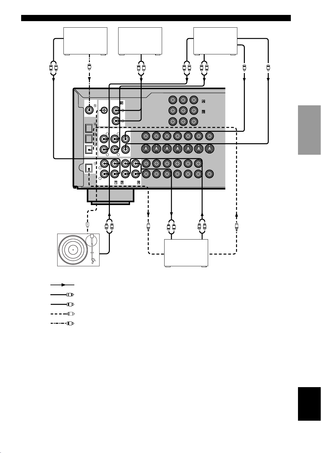
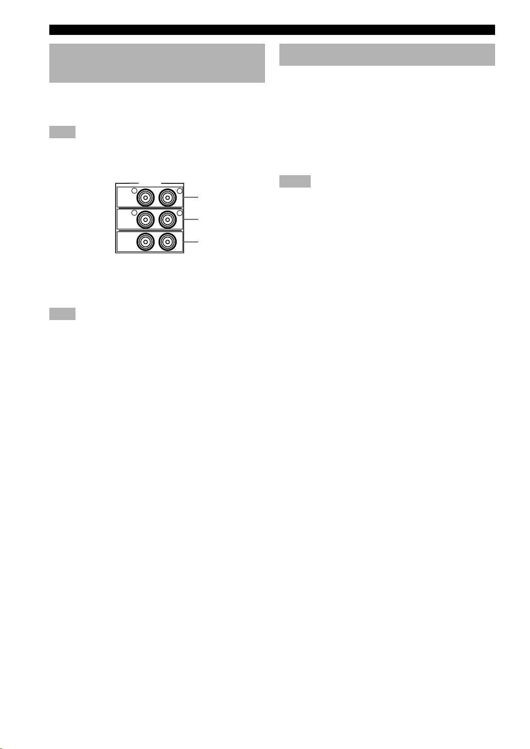
Connecting Audio Components
■ Connecting to digital jacks
This unit has digital jacks for direct transmission of
digital signals through either coaxial or fiber optic cables.
You can use the digital jacks to input PCM, Dolby Digital
and DTS bitstreams. When you connect components to
both the COAXIAL and OPTICAL jacks, priority is given
to the input signals from the COAXIAL jack. All digital
input jacks are acceptable for 96-kHz sampling digital
signals.
y
• You can designate the input for each digital jack according to
your component by using “4 I/O ASSIGNMENT” on the SET
MENU.
About the dust protection cap
Pull out the cap from the optical jack
before you connect the fiber optic cable.
Do not discard the cap. When you are not
using the optical jack, be sure to put the
cap back in place. This cap protects the
jack from dust.
Note
• The OPTICAL jacks on this unit conform to the EIA standard.
If you use a fiber optic cable that does not conform to this
standard, this unit may not function properly.
■ Connecting a turntable
PHONO jacks are for connecting a turntable with an MM
or high-output MC cartridge. If you have a turntable with
a low-output MC cartridge, use an inline boosting
transformer or MC-head amplifier when connecting to
these jacks.
y
• The GND terminal does not electrically ground the turntable. It
simply reduces noise in the signal. In some cases, you may
hear less noise if you do not connect to the GND terminal.
■ Connecting a tuner
You can listen to an FM or AM broadcasting by
connecting AM/FM tuner.
To get clearer reception, connect the antennas correctly.
Refer to your tuner’s operation instrustions for details.
■ Connecting a CD player
y
• The COAXIAL jack is available for a CD player which has a
coaxial digital output jack.
• When you connect a CD player to both the analog and digital
jacks, priority is given to the input signals from the digital jack.
■ Connecting an MD recorder, CD
recorder or tape deck
y
• When you connect your recording component to both the
analog and digital input and output jacks, the priority is given
to the digital signal.
Notes
• When you connect a recording component to this unit, keep its
power on while using this unit. If the power is off, this unit
may distort the sound from other components.
• Since digital output and analog output (REC OUT) are
independent of each other, the analog signal is output only to
the analog jack, while the digital signal is output only to the
digital jack.
12
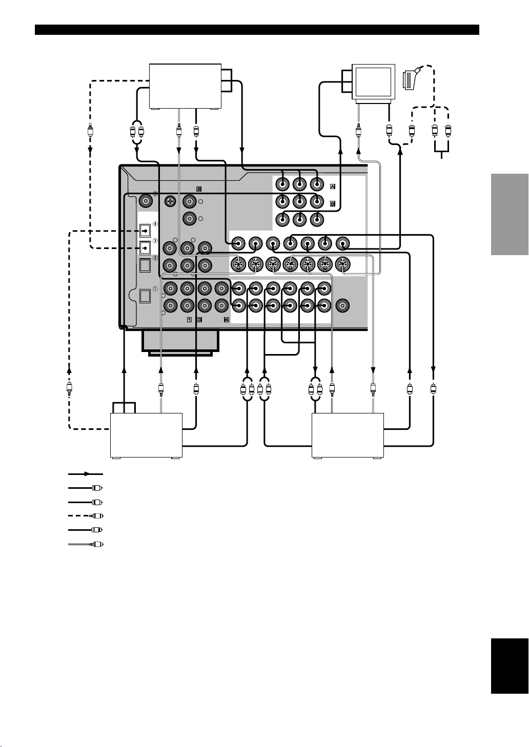
Page 15
CONNECTIONS
OUTPUT
R
L
(Europe model)
CD player
C
DIGITAL
INPUT
CD
COAXIAL
OPTICAL
D-TV/CBL
DVD
MD/CD-R
OPTICAL
MD/CD-R
DIGITAL
OUTPUT
COAXIAL
OUTPUT
GND
MAIN
RLR
L
R
PHONO
TUNER
6CH INPUT
SURROUND
CD
AM/FM Tuner
L
R
CENTER
L
SUB WOOFER
OUT(REC)
IN(PLAY)
MD/CD-R
R
L
AUDIO SIGNAL
MAIN
OUTPUT
SUBWOOFER
OUTPUT
External decoder
INTRODUCTION
R
VCR 2
/DVR
D-TV/CBL
OUT
L
DVD
MONITOR
OUT
R
SURROUND
OUTPUT
MONITOR OUT
VIDEO
S VIDEO
CENTER
OUTPUT
PREPARATION
L
D-TV/CBL
DVD
YPB/CBPR/CRCOMPONENT VIDEO
VCR 1
IN
OUT IN
VIDEO SIGNAL
BASIC OPERA-
IN
DVD
D-TV/CBL
VCR 1
OUT IN
VCR 2/DVR
OUT
SUB
WOOFER
OUTPUT
TION
GND
L R
OUTPUT
Turntable
indicates signal direction
L
indicates left analog cables
R
indicates right analog cables
O
indicates optical cables
C
indicates coaxial cables
L R
INPUT OUTPUT
MD recorder
or
OPTICAL
INPUT
CD recorder
L R
OPTICAL
OUTPUT
OO
OPERATION
ADVANCED
INFORMATION
ADDITIONAL
APPENDIX
English
13
Page 16
CONNECTIONS
Connecting Video Components
■ About the video jacks
There are three types of video jacks. Video signals input through the VIDEO jacks are the conventional composit video
signals. Video signals input through the S VIDEO jacks are separated into luminance (Y) and color (C) video signals.
The S-video signals achieve high-quality color reproduction. Video signals input through the COMPONENT VIDEO
jacks are separated into luminance (Y) and color difference (P
into three for each signal. The description of the component video jacks may be different depending on the component
(e.g. Y, C
, CR/Y, PB, PR/Y, B-Y, R-Y etc.). Component video signals provide the best quality in picture reproduction.
B
If your video component has an S-video output or component video output, you can connect it to this unit. Connect the
S-video signal output jack on your video component to the S VIDEO jack or connect the component signal output jacks
on your video component to the COMPONENT VIDEO jacks.
VIDEO jack (composite)
S VIDEO jack
YPB/CBPR/C
COMPONENT VIDEO jacks
R
Notes
• Use a commercially available S-video cable when connecting to the S VIDEO jack, and commercially available video cables when
connecting to the COMPONENT VIDEO jacks.
• When you are using the COMPONENT VIDEO jacks, check the details in the owner’s manual that came with the component being
connected.
, PR/CR) video signals. The jacks are also separated
B/CB
y
• Each type of video jack works independently. Signals input
through the composite video, S-video and component jacks are
output through the corresponding composite video, S-video,
and component jacks, respectively.
• If you make S-video connections to this unit, it is not necessary
to make composite video connections. If both types of
connections are made, this unit gives priority to the S-video
signal.
• You can designate the input for the COMPONENT VIDEO A
and B jacks according to your component by using “4 I/O
ASSIGNMENT” on the SET MENU.
■ Video monitor with a 21-pin connector (Europe and U.K. models only)
Make a connection as shown on page 15 with a commercially available SCART-plug connector cable.
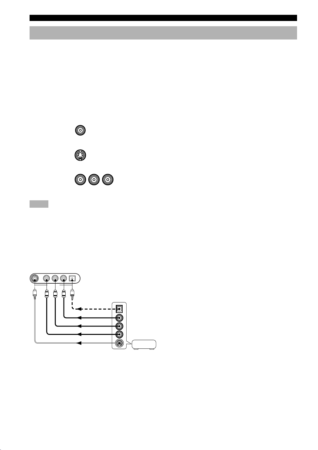
■ VIDEO AUX jacks (on the front panel)
S VIDEO VIDEO L AUDIO R OPTICAL
VIDEO AUX
S
V
R
L
O
OPTICAL OUT
AUDIO OUT R
AUDIO OUT L
VIDEO OUT
S VIDEO OUT
Game console
These jacks are used to connect any video input source
such as a game console to this unit.
14
Page 17
CONNECTIONS
O
OPTICAL
OUTPUT
AUDIO
OUTPUT
R
L
COAXIAL
OPTICAL
D-TV/CBL
OPTICAL
S VIDEO
OUTPUT
DIGITAL
INPUT
CD
DVD
MD/CD-R
MD/CD-R
DIGITAL
OUTPUT
DVD player
S
GND
TUNER
6CH INPUT
MAIN
SURROUND
RLR
L
R
CD
PHONO
VIDEO
OUTPUT
V
L
R
CENTER
L
SUB WOOFER
IN(PLAY)
MD/CD-R
OUT(REC)
COMPONENT
OUTPUT
DVD
D-TV/CBL
D-TV/CBL
DVD
AUDIO SIGNAL
COMPONENT
INPUT
S VIDEO
INPUT
DVD
D-TV/CBL
MONITOR
VCR 2
/DVR
VCR 2/DVR
OUT
OUT
OUT
MONITOR OUT
WOOFER
YPB/CBPR/CRCOMPONENT VIDEO
VCR 1
IN
OUT IN
VIDEO SIGNAL
IN
OUT IN
VCR 1
SUB
OUTPUT
Monitor
VIDEO
S
VIDEO
S VIDEO
INPUT
SCART-plug (Europe
and U.K. models only)
V
L
V
R
No connection
(Europe model)
INTRODUCTION
PREPARATION
BASIC OPERA-
TION
COMPONENT
OUTPUT
O
OPTICAL
OUTPUT
S VIDEO
OUTPUT
S
TV/digital TV
or cable TV/
satellite tuner
VIDEO
OUTPUT
AUDIO
V
R
L
INPUT
R
L
S VIDEO
OUTPUT
S
R
L
VCR 1 or VCR 2/
DVR (digital video
recorder)
S VIDEO
INPUT
S
V
VIDEO
OUTPUT
V
AUDIO OUTPUTAUDIO OUTPUT VIDEO INPUT
indicates signal direction
L
indicates left analog cables
R
indicates right analog cables
O
indicates optical cables
V
indicates video cables
S
indicates S-video cables
When using an LD player
Connect the LD player output to the DVD jack.
If the LD player has an OPTICAL digital output jack, connect it to this unit’s OPTICAL DVD jack. If it has analog
jacks, connect it to the analog DVD jacks. If it has an “RF OUTPUT jack” to output a Dolby Digital RF signal (AC-3),
use a commercially available RF demodulator and connect it to the OPTICAL DVD jack.
If connecting a DVD player and an LD player, connect the LD player to the digital input jack (ex. D-TV/CBL) or to the
analog input jack (D-TV/CBL, VCR 1 or VCR 2/DVR). For details on connections and operations, refer to the
operation instructions for the LD player.
Note that this unit’s remote control can be used to operate the LD player by setting the corresponding manufacturer
code for the DVD/LD position.
OPERATION
ADVANCED
INFORMATION
ADDITIONAL
APPENDIX
English
15
Page 18
CONNECTIONS
Connecting the Speakers
Be sure to connect the left channel (L), right channel (R), “+” (red) and “–” (black) properly. If the connections are
faulty, no sound will be heard from the speakers, and if the polarity of the speaker connections is incorrect, the sound
will be unnatural and lack bass.
CAUTION
• Use speakers with the specified impedance shown on the rear panel of this unit.
• Do not let the bare speaker wires touch each other and do not let them touch any metal part of this unit. This could
damage the unit and/or speakers.
If necessary, use the SET MENU to change the speaker mode settings according to the number and size of the speakers
in your configuration after you finish connecting your speakers.
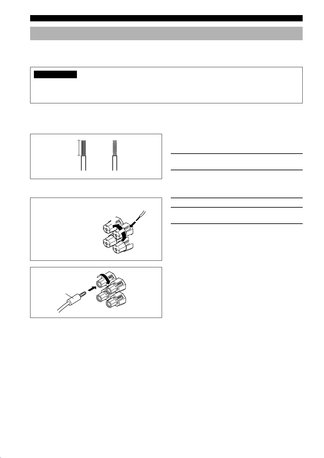
■ Speaker cables
A speaker cord is actually a pair of insulated cables
10 mm (3/8”)
running side by side. One of the cables is colored or
shaped differently, perhaps with a stripe, groove or ridge.
1 Remove approx. 10 mm (3/8”) of insulation
12
from each of the speaker cables.
2 Twist the exposed wires of the cable
together to prevent short circuits.
■ Connecting to the SPEAKERS terminals
Red: positive (+)
Black: negative (–)
2
1
1 Unscrew the knob.
2 Insert one bare wire into the hole in the side
of each terminal.
3 Tighten the knob to secure the wire.
3
y
(China and General models only)
• Banana plug connections are also possible. First, tighten the
Banana plug
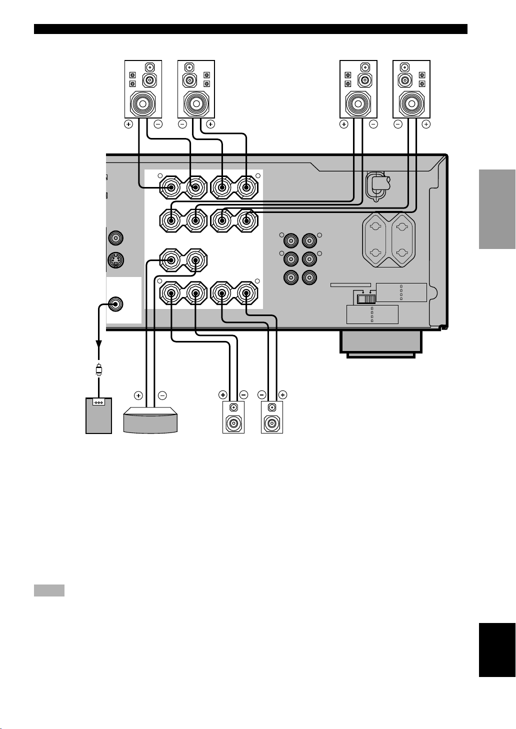
■ MAIN SPEAKERS terminals
One or two speaker systems can be connected to these terminals. If you use only one speaker system, connect it to either
of the MAIN A or B terminals.
■ REAR SPEAKERS terminals
A rear speaker system can be connected to these terminals.
■ CENTER SPEAKER terminals
A center speaker can be connected to these terminals.
knob and then insert the banana plug connector into the end of
the corresponding terminal.
16
Page 19
CONNECTIONS
T
/
(Europe model)
Right
D
CBL
OR
T
OMPONENT VIDEO
MONITOR OUT
SUB
WOOFER
OUTPUT
Main speakers A
A
MAIN
B
VIDEO
CENTER
S VIDEO
REAR
(SURROUND)
Left
SPEAKERS
+ –
R L
+ –
+ ––+
R
– +
L
R
MAIN
R
REAR
(SURROUND)
CENTER
Main speakers B
Right Left
AC OUTLETS
OUTPUT
L
L
IMPEDANCE SELECTOR
SET BEFORE POWER ON
MAIN A OR B: 4
A + B: 8
CENTER
REAR
SWITCHED
100W MAX. TOTAL
MAIN A OR B: 8
CENTER
REAR
MIN. /SPEAKER
MIN. /SPEAKER
: 6
MIN. /SPEAKER
: 6
MIN. /SPEAKER
MAINS
A + B:16
MIN. /SPEAKER
MIN. /SPEAKER
: 8
MIN. /SPEAKER
: 8
MIN. /SPEAKER
INTRODUCTION
PREPARATION
BASIC OPERA-
TION
OPERATION
ADVANCED
Right Left
Subwoofer
system
Center speaker Rear speakers
INFORMATION
ADDITIONAL
■ SUBWOOFER jack
When using a subwoofer with built-in amplifier,
including the YAMAHA Active Servo Processing
Subwoofer System, connect the input jack of the
subwoofer system to this jack. Low bass signals
distributed from the main, center and/or rear channels are
directed to this jack. (The cut-off frequency of this jack is
90 Hz.) The LFE (low-frequency effect) signals generated
when Dolby Digital or DTS is decoded are also directed
if they are assigned to this jack.
Notes
• Adjust the subwoofer volume according to the operating
instructions for the subwoofer. (Fine adjustment is possible
using this unit’s output level control of the effect speakers.)
• Depending on the settings of “1 SPEAKER SET”, “6 DOLBY
D. SET” and “7 DTS SET” on the SET MENU, some signals
may not be output from the SUBWOOFER jack.
APPENDIX
English
17
Page 20
CONNECTIONS
Connecting an External Amplifier (Europe and U.K. models only)
If you want to increase the power output to the speakers,
or want to use another amplifier, connect an external
amplifier to the OUTPUT jacks as follows.
Note
• When RCA pin plugs are connected to the OUTPUT jacks for
output to an external amplifier, do not use the corresponding
SPEAKERS terminals.
OUTPUT
R
MAIN
R
REAR
(SURROUND)
CENTER
1 MAIN jacks
Main channel line output jacks.
Note
• The signals output through these jacks are affected by the
BASS, TREBLE and BASS EXTENSION settings.
2 REAR (SURROUND) jacks
Rear channel line output jacks.
L
1
L
2
3
Connecting an External Decoder
This unit is equipped with 6 additional input jacks (left
and right MAIN, CENTER, left and right SURROUND
and SUBWOOFER) for discrete multi-channel input from
an external decoder, sound processor or pre-amplifier.
Connect the output jacks on your external decoder to the
6CH INPUT jacks. Be sure to match the left and right
outputs to the left and right input jacks for the main and
surround channels.
Notes
• When you select 6CH INPUT as the input source, this unit
automatically turns off the digital sound field processor, and
you cannot listen to DSP programs.
• When you select 6CH INPUT as the input source, changing
items 1A to 1D on the SET MENU is not affected.
3 CENTER jacks
Center channel line output jacks.
18
Page 21

IMPEDANCE SELECTOR Switch
CONNECTIONS
WARNING
Do not change the IMPEDANCE SELECTOR switch setting while the power of this unit is on, otherwise the unit
may be damaged.
If this unit fails to turn on when STANDBY/ON (or POWER) is pressed, the IMPEDANCE SELECTOR switch may
not be fully slid to either position. If so, slide the switch to either position fully when this unit is in the standby
mode.
Select the left or right position according to the impedance of the speakers in your system. Be sure to move this switch
only when this unit is in the standby mode.
VOLTAGE SELECTOR
VOLTAGE SELECTOR
(General model)
AC OUTLETS
SWITCHED
100W MAX.
TOTAL
IMPEDANCE SELECTOR
SET BEFORE POWER ON
MAIN A OR B: 4
A + B: 8
CENTER
REAR
MIN. /SPEAKER
MIN. /SPEAKER
: 6
MIN. /SPEAKER
: 6
MIN. /SPEAKER
MAIN A OR B: 8
A + B:16
CENTER
REAR
MIN. /SPEAKER
MIN. /SPEAKER
: 8
MIN. /SPEAKER
: 8
MIN. /SPEAKER
IMPEDANCE SELECTOR
Switch
position
Left
Right
Speaker Impedance level
If you use one set of main speakers, the impedance of
each speaker must be 4 Ω or higher.
Main
If you use two sets of main speakers, the impedance of
each speaker must be 8 Ω or higher.
Center
Rear
The impedance must be 6 Ω or higher.
The impedance of each speaker must be 6 Ω or higher.
If you use one set of main speakers, the impedance of
Main
each speaker must be 8 Ω or higher.
If you use two sets of main speakers, the impedance of
each speaker must be 16 Ω or higher.
Center The impedance must be 8 Ω or higher.
Rear
The impedance of each speaker must be 8 Ω or higher.
■ VOLTAGE SELECTOR (China and General models only)
The VOLTAGE SELECTOR on the rear panel of this unit must be set for your local main voltage BEFORE plugging
into the AC main supply. Voltages are 110/120/220/240 V AC, 50/60 Hz.
INTRODUCTION
PREPARATION
OPERAIONT
BASIC
OPERATION
ADVANCED
Connecting the Power Supply Cords
After completing all connections, connect the AC power cord to an AC power outlet. Disconnect the AC power cord if
you will not use this unit for a long period of time.
■ AC OUTLET(S) (SWITCHED)
IMPEDANCE SELECTOR
SET BEFORE POWER ON
MAIN A OR B: 4
A + B: 8
CENTER
REAR
(Europe model)
MAINS
AC OUTLETS
SWITCHED
100W MAX. TOTAL
MAIN A OR B: 8
A + B:16
CENTER
: 8
REAR
: 8
MIN. /SPEAKER
MIN. /SPEAKER
: 6
MIN. /SPEAKER
: 6
MIN. /SPEAKER
SWITCHED
MIN. /SPEAKER
MIN. /SPEAKER
MIN. /SPEAKER
MIN. /SPEAKER
To AC outlet
Europe, China and General models ............. 2 OUTLETS
U.K. model ..................................................... 1 OUTLET
Use these outlets to connect the power cords only from
your audio/video components to this unit. The power to
the AC OUTLET(S) is controlled by this unit’s
STANDBY/ON (or POWER and STANDBY). These
outlets will supply power to any connected component
whenever this unit is turned on. The maximum power
(total power consumption of components) that can be
connected to the AC OUTLET(S) is 100 W.
19
INFORMATION
ADDITIONAL
APPENDIX
English
Page 22
ON-SCREEN DISPLAY (OSD)
You can display the operation information for this unit on
a video monitor. If you display the SET MENU and DSP
program parameter settings on a monitor, it is much easier
to see the available options and parameters than it is by
reading this information on the front panel display.
y
• If a video source is being reproduced, the OSD is
superimposed over the image.
• The OSD signal is not output to the REC OUT jack, and will
not be recorded with any video signal.
• You can set the OSD to turn on (blue background) or off when
a video source is not being reproduced (or the source
component is turned off) by using “9 DISPLAY SET” on the
SET MENU.
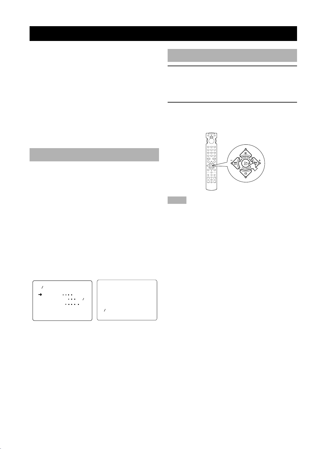
OSD Modes
You can change the amount of information the OSD
shows.
Full display
This mode always shows the DSP program parameter
settings on the video monitor.
Short display
This mode briefly shows the same contents as the front
panel display at the bottom of the screen and then
disappears.
Display off
This mode briefly shows the “DISPLAY OFF” message
at the bottom of the screen and then disappears.
Afterwards, no changes to operations appear on the
monitor except those of the ON SCREEN button.
P01 CONCERT HALL
INIT. DLY
ROOM SIZE 1.0
LIVENESS
45ms
5
P01 CONCERT HALL
Selecting the OSD Mode
1 When you turn on the power, the video
monitor and front panel display show the
level of the main volume for a few seconds
and then switch to show the current DSP
program.
2 Press ON SCREEN on the remote control
repeatedly to change the display mode.
The OSD mode changes in the following order: full
display, short display, and display off.
Notes
• If you choose a video input source that has a component
connected to both the S VIDEO IN and composite VIDEO IN
jacks, and both the S VIDEO OUT and composite VIDEO
OUT jacks are connected to a video monitor, the video signal is
output to both the S VIDEO OUT and VIDEO OUT jacks.
However, the OSD is carried only on the S-video signal. If no
video signal is input, the OSD is carried on both the S-video
and composite video signals.
• If your video monitor is connected only to the COMPONENT
VIDEO jacks of this unit, the OSD is not shown. Make sure to
connect your video monitor to the COMPONENT VIDEO
jacks and either VIDEO or S VIDEO jacks if you want to see
the OSD.
• Playing back video software that has an anti-copy signal or
video signals with a lot of noise may produce unstable images.
Full display Short display
y
• When you choose the full display mode, INPUT l / h,
VOLUME and some other types of operation information are
displayed at the bottom of the screen in the same format as that
for the front panel display.
• The SET MENU and test tone display appear regardless of the
OSD mode.
20
Page 23
SPEAKER MODE SETTINGS
This unit is equipped with a main amplifier capable of handling 5.1 channel. Although up to 6 speakers can be
connected, it is possible to select the speaker mode that gives the best sound field effect according to the number and
size of speakers being used.
Before use, please set the speaker mode setting using “1 SPEAKER SET” on the SET MENU described on page 32.
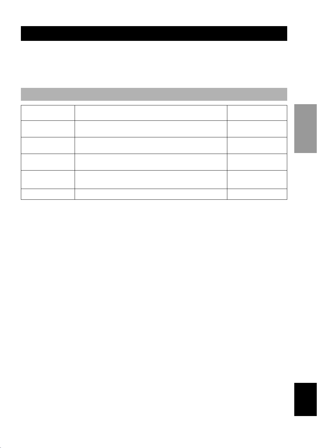
Summary of SPEAKER SET Items 1A through 1E
Item Description
1A CENTER SP
1B MAIN SP
1C REAR L/R SP
1D LFE/BASS OUT
1E MAIN LEVEL Selects the main speaker level.
Selects the output mode according to whether or not a center speaker is
being used and its performance.
Selects the output mode according to the performance of the main
speakers.
Selects the output mode according to whether or not rear L/R speakers
are being used and their performance.
Selects the speaker according to use for LFE signal output and low bass
signal.
Control value (default
setting indicated in bold)
LRG/SML/NONE
LARGE/SMALL
LRG/SML/NONE
SWFR/MAIN/BOTH
Normal/–10 dB
INTRODUCTION
PREPARATION
OPERAIONT
BASIC
OPERATION
ADVANCED
21
INFORMATION
ADDITIONAL
APPENDIX
English
Page 24
ADJUSTING THE SPEAKER OUTPUT LEVELS
This section explains how to adjust the speaker output
levels by using the test tone generator. When this
adjustment is made, the output level heard at the listening
position will be the same from each speaker. This is
important for the best performance of the digital sound
field processor, the Dolby Pro Logic decoder, Dolby
Digital decoder and DTS decoder.
Note
• Since this unit cannot enter the test mode while headphones are
connected to this unit, be sure to unplug the headphones from
the PHONES jack when using the test tone.
Before You Begin
1
VOLUME
6CH INPUTINPUT MODE
INPUT
STANDBY
EXTENSION
/ON
BASS
3
BASS TREBLE SPEAKERS
–+–
+
3
DIGITAL
SURROUND
AB
ONOFFON
OFF
2
DIGITAL
PROGRAM
– +
PHONES S VIDEO VIDEO L AUDIO R OPTICAL
SILENT VIDEO AUX
DSP
EFFECTSET MENU
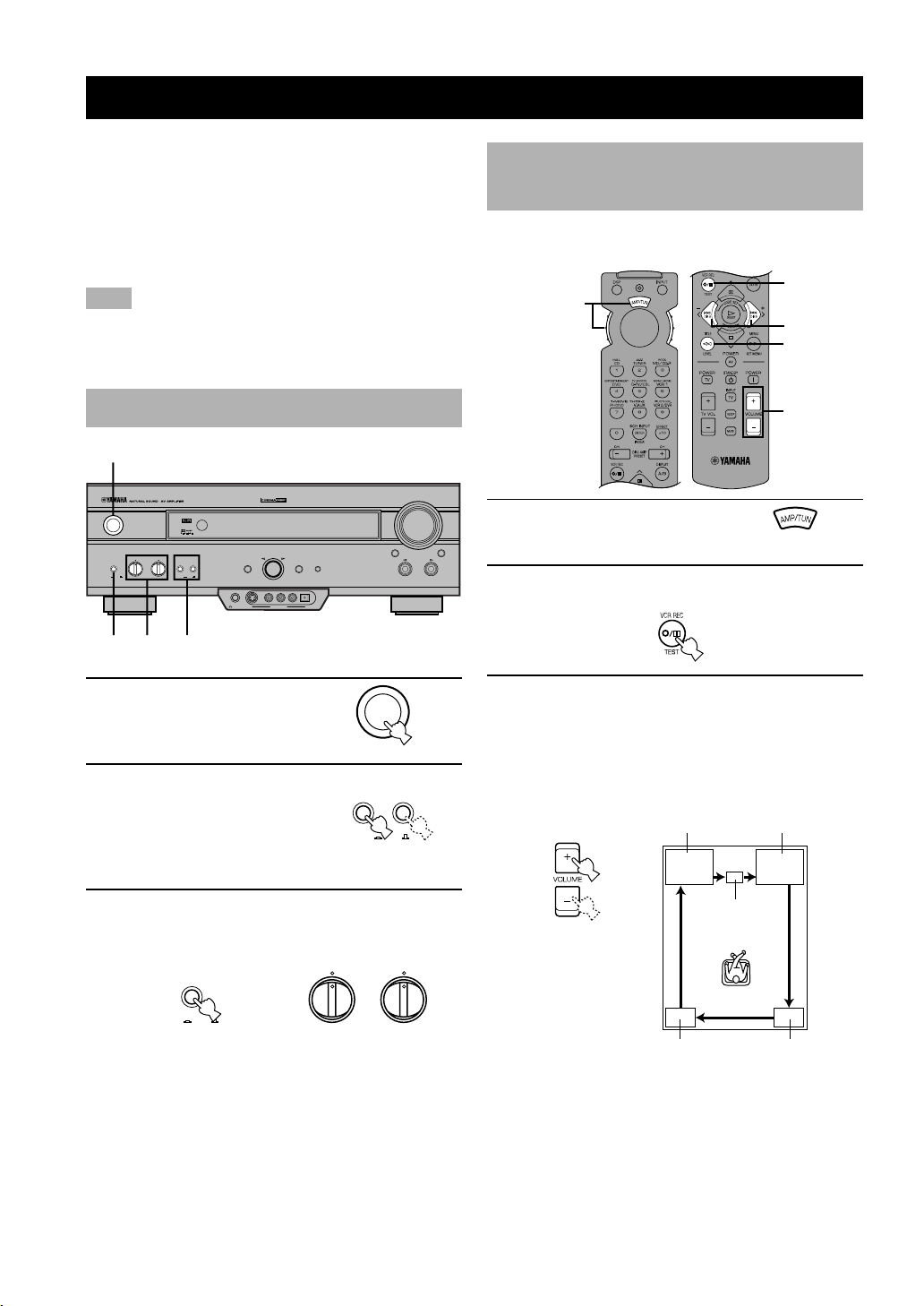
Using the Test Tone (TEST DOLBY SUR.)
The adjustment of each speaker output level should be
made at your listening position with the remote control.
2,6
A/B/C/D/E
1
5
4
3
A/B/C/D/E
1 Set the selector dial to the
AMP/TUN (or DSP/TUN)
position.
2 Press TEST to output the test tone.
1 Press STANDBY/ON to
turn on the power. Turn on
the video monitor.
2 Press SPEAKERS A or B
to select the main
speakers to be used.
If you are using two sets of the
main speakers, press both A
and B.
STANDBY
/ON
SPEAKERS
AB
OFF
ON
3 Set BASS and TREBLE on the front panel to
the center position and set BASS
EXTENSION to OFF.
BASS
EXTENSION
OFFON
Set to OFF.
BASS TREBLE
–
+
–
+
3 Adjust the volume so you can hear the test
tone.
The test tone is heard from the left main speaker,
center speaker, right main speaker, right rear speaker
and left rear speaker in order. The tone is produced
for 2.5 seconds each time.
LEFT
(TEST LEFT)
(TEST CENTER)
LEFT SURROUND
(TEST L SUR.)
RIGHT
(TEST RIGHT)
CENTER
RIGHT SURROUND
(TEST R SUR.)
22
Page 25
CONNECTIONSADJUSTING THE SPEAKER OUTPUT LEVELS
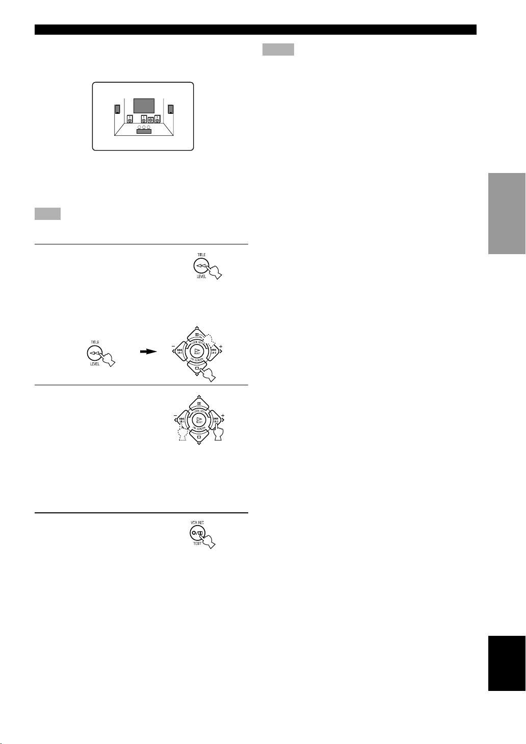
The state of the test tone output is also shown on the
monitor by an image of the audio listening room.
This is convenient for adjusting each speaker level.
TEST DOLBY SUR.
LEFT
y
• If “1A CENTER SP” on the SET MENU is set to NONE, the
center channel sound is automatically output from the left and
right main speakers.
Note
• If the test tone cannot be heard, turn down the volume, set the
unit in the standby mode and check the speaker connections.
4 Press LEVEL repeatedly
to select the speaker to be
adjusted.
y
• Once you press LEVEL, you can also select the speaker to be
adjusted by pressing d. (Pressing u changes the selection in
the reverse order.)
Notes
• For details on adjusting the subwoofer speaker, refer to the
effect speaker level adjustment described on page 38.
• After adjusting with the test tone, it is possible to adjust the
speaker level to taste while listening to the playback of an
actual source when using the effect speaker level adjustment
described on page 38.
y
• You can increase the output levels of the effect speakers
(center, left rear and right rear) to +10 dB. If the output level of
these speakers is lower than that of the main speakers even
after you have increased the output level of these speakers up
to +10 dB, set “1E MAIN LEVEL” on the SET MENU to
–10 dB. This setting decreases the main speaker output level to
about one-third of the normal level. After you have set “1E
MAIN LEVEL” on the SET MENU to –10 dB, adjust the
levels for the center and rear speakers again.
INTRODUCTION
PREPARATION
OPERAIONT
BASIC
5 Press j / i repeatedly to
adjust the output level of
the currently selected
speaker so that it
becomes almost the
same as that of the main
speaker.
• While adjusting, the test tone is heard from the
selected speaker.
• Repeat steps 4 and 5 to adjust the output levels of
the center, left rear and right rear speakers.
6 When the adjustment is
complete, press TEST.
The test tone stops and the
current DSP program appears
on the front panel display and
on the video monitor.
OPERATION
ADVANCED
INFORMATION
ADDITIONAL
APPENDIX
English
23
Page 26
BASIC OPERATION
BASIC PLAYBACK
When using the remote control, set the selector dial to
the AMP/TUN position.
1
STANDBY
EXTENSION
/ON
BASS
BASS TREBLE SPEAKERS
–+–
+
5
6
DIGITAL
SURROUND
AB
OFF
ONOFFON
2
DIGITAL
PROGRAM
– +
PHONES S VIDEO VIDEO L AUDIO R OPTICAL
SILENT VIDEO AUX
DSP
EFFECTSET MENU
A/B/C/D/E
56
VOLUME
INPUT
3
1
3
A/B/C/D/E
5
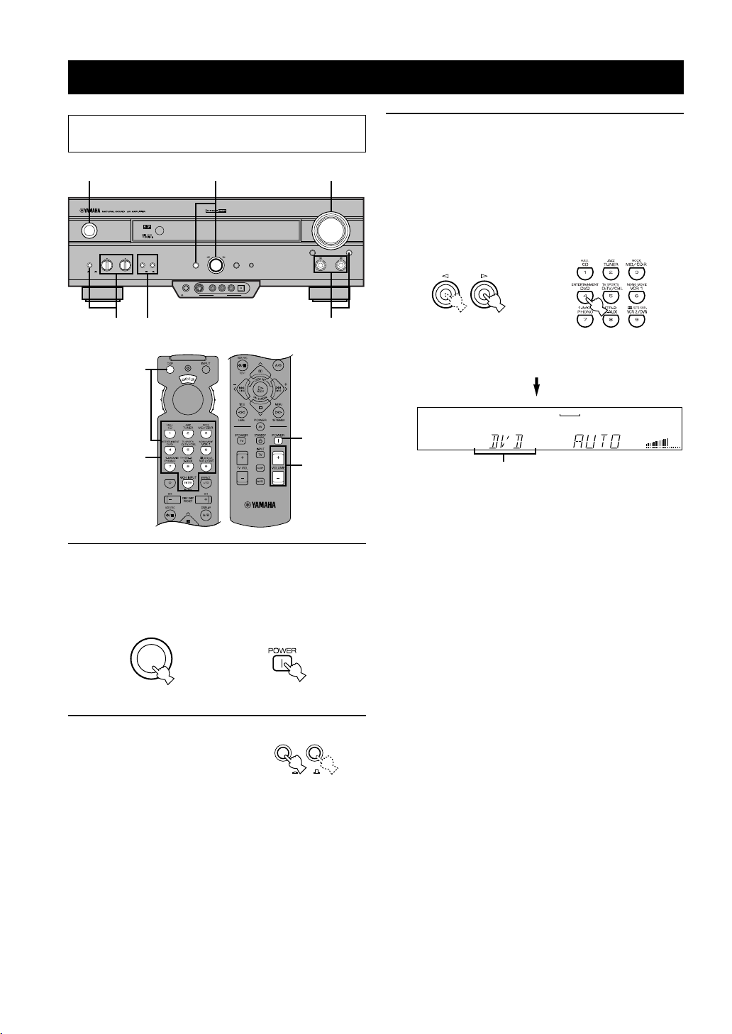
1 Press STANDBY/ON (or POWER) to turn on
the power. Turn on the video monitor.
The front panel display and the video monitor show
the level of the main volume for a few seconds and
then switch to show the current DSP program.
STANDBY
/ON
2 Press SPEAKERS A or B
to select the main
speakers to be used.
If you are using two sets of
main speakers, press both A
and B.
or
Remote controlFront panel
SPEAKERS
AB
ON
OFF
Front panel
3 Press INPUT l / h repeatedly (or press one
of the input selector buttons) to select the
input source.
• The current input source is indicated on the front
panel display with a cursor.
• The current input source name and input mode
appear on the front panel display and on the video
6CH INPUTINPUT MODE
monitor for a few seconds.
INPUT
or
Front panel
VCR2/DVR
V-AUX
VCR 1
D-TV/CBL
Remote control
MD/CD-R
DVD
CDTUNER PHONO
VOLUME
Selected input source
Select this: To reproduce the signal from
this component
PHONO: Turntable
CD: CD player
TUNER: AM/FM tuner
MD/CD-R: MD recorder/CD recorder/tape deck
DVD: DVD player
D-TV/CBL: TV/digital TV or cable TV/satellite
tuner
VCR 1: Video cassette deck 1
VCR 2/DVR: Video cassette deck 2/digital
video recorder
V-AUX: Another audio/video component
(connected to the VIDEO AUX
jacks on the front panel)
24
Page 27
BASIC PLA YBACK
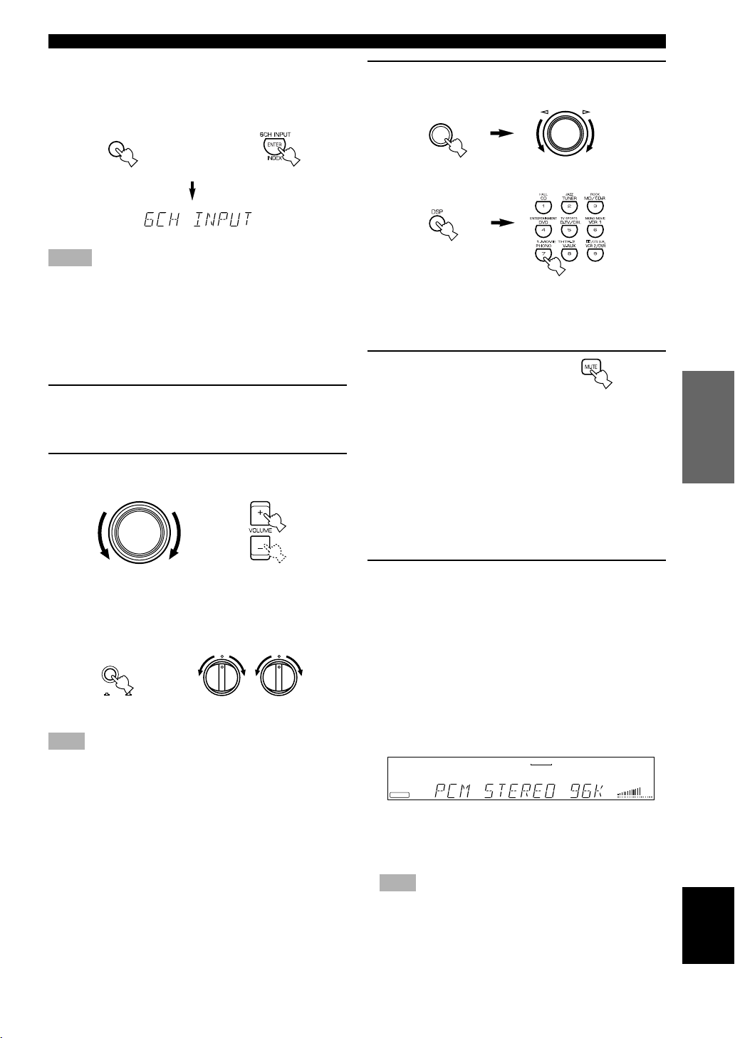
To select a source connected to the 6CH INPUT
jacks
Press 6CH INPUT until “6CH INPUT” appears on the
front panel display and on the video monitor.
6CH INPUT
or
Front panel
Remote control
Notes
• If “6CH INPUT” is shown on the front panel display and on
the video monitor, no other source can be played. To select
another input source with INPUT l / h (or the input selector
buttons), press 6CH INPUT to turn off “6CH INPUT” from the
front panel display and the video monitor.
• If you want to enjoy an audio source connected to the 6CH
INPUT jacks together with a video source, first select the video
source and then press 6CH INPUT.
4 Start playback (or select a broadcast station)
on the source component.
Refer to the operation instructions for the
component.
5 Adjust the volume to the desired output
level.
VOLUME
or
Front panel Remote control
If desired, use BASS, TREBLE and BASS
EXTENSION etc. These controls are only effective
for sound from the main speakers.
BASS
EXTENSION
OFFON
Front panel
Note
• If the component connected to the VCR 1 OUT, VCR 2/DVR
OUT and MD/CD-R OUT jacks is turned off, the reproduced
sound may be distorted or the volume may be lowered. In these
cases, turn on the component.
BASS TREBLE
–
+
–
+
6 Use the digital sound field processor.
See “Selecting a Sound Field Program”.
DSP
PROGRAM
D-TV/CBL
–+
MD/CD-R
DVD
CDTUNER PHONO
VOLUME
Front panel
or
Remote control
■ To mute the sound
Use this when you want to temporarily mute audio
output.
Press MUTE on the
remote control.
To restore the audio output to
the previous volume level,
press MUTE again.
y
• You can also cancel mute to press any operation buttons such as
VOLUME +/–.
• During muting, “MUTE ON” appears on the front panel
display and on the video monitor.
■ When you have finished using
this unit
Press STANDBY/ON (or STANDBY) to set
this unit in the standby mode.
■ Notes on the digital signal
The digital input jacks of this unit can also handle
96-kHz sampling digital signals. (To utilize this, use a
source that supports 96-kHz sampling digital signals and
set the player for digital output. Refer to the operation
instructions for the player.) Note the following when a
96-kHz sampling digital signal is input to this unit:
1. The following indication will appear on the front panel
display.
VCR 1
VCR2/DVR
V-AUX
PCM
INTRODUCTION
PREPARATION
OPERATION
BASIC
OPERATION
ADV ANCED
INFORMATION
ADDITIONAL
APPENDIX
2. DSP programs cannot be selected. Sound will be
output as normal 2-channel stereo sound from only the
left and right main speakers.
Note
• If “1B MAIN SP” on the SET MENU is set to SMALL and
“1D LFE/BASS OUT” is set to SWFR, or “1D LFE/BASS
OUT” is set to BOTH, the sound is also output from the
subwoofer.
3. Adjustment of the speaker output level (except for
subwoofer output level) described on page 38 cannot
be made.
English
25
Page 28
BASIC PLAYBACK
■ BGV (background video) function
The BGV function allows you to combine a video image
from a video source with a sound from an audio source.
(For example, you can listen to classical music while you
are watching a video.)
Select a source from the video group and then select a
source from the audio group with the input selector
buttons on the remote control. The BGV function does
not work if you select the sources with INPUT l / h on
the front panel.
Input Modes and Indications
When using the remote control, set the selector dial to
the AMP/TUN position.
This unit comes with various input jacks. If your
component is connected to more than one type of input
jack, you can set the priority of the input signal.
Press INPUT MODE (or the input selector
button that you have pressed to select the
input source on the remote control)
repeatedly until the desired input mode is
shown on the front panel display and on the
video monitor.
AUTO: In this mode, the input signal is
automatically selected in the
following order:
1) Dolby Digital or DTS signal
2) Digital (PCM) signal
3) Analog signal
DTS: In this mode, only the digital input
signal encoded with DTS is selected
even if another signal is input at the
same time.
ANLG (ANALOG): In this mode, only the analog input
signal is selected even if a digital
signal is input at the same time.
Notes
• If digital signals are input from both the COAXIAL and
OPTICAL jacks, the digital signal from the COAXIAL jack is
selected.
• When AUTO is selected, this unit automatically determines the
type of signal. If this unit detects a Dolby Digital or DTS
signal, the decoder automatically switches to the appropriate
setting and reproduces 5.1 channel source.
• The sound output may be interrupted for some LD players and
DVD players in the following situation:
When the input mode has been set to AUTO and a search is
performed while playing the source encoded with a Dolby
Digital or DTS signal, the sound may delay for a moment when
playback is resumed.
• Depending on the LD player, playback may not be made when
playing an LD that is not digitally recorded with the input
mode set to AUTO. If this happens, set the input mode to
ANALOG.
26
INPUT MODE
Front panel
VCR2/DVR
V-AUX
VCR 1
or
D-TV/CBL
Remote control
MD/CD-R
DVD
Input mode
CDTUNER PHONO
VOLUME
Page 29

■ Notes on playing a source
encoded with a DTS signal
• If the digital output data of the player has been
processed in any way, you may not be able to
perform DTS decoding even if you make a digital
connection between this unit and the player.
• If you play a source encoded with a DTS signal and
set the input mode to ANALOG, this unit reproduces
the noise of an unprocessed DTS signal. When you
want to play a DTS source, be sure to connect the
source to a digital input jack and set the input mode
to AUTO or DTS.
• If you switch the input mode to ANALOG while
playing a source encoded with a DTS signal, this unit
reproduces no sound.
• The following phenomena may occur if the input
mode is set to AUTO when playing back source
encoded with a DTS signal.
– If you continue to play a source encoded with a DTS
signal, this unit automatically switches to the “DTS-
decoding” mode to prevent noise from being
generated during subsequent operation. (The “t”
indicator lights up on the front panel display.) The
“t” indicator may flash immediately after
playback of a source encoded with a DTS signal has
finished. Only a source encoded with a DTS signal
can be played back while this indicator is flashing.
(The indicator will flash for less than a minute.) If
you want to play a normal PCM source soon, set the
input mode back to AUTO.
– The “t” indicator may flash when a search or
skip operation is performed. If this status continues
for a certain length of time, the unit will
automatically switch from the “DTS-decoding”
mode to PCM digital signal input mode and the
“t” indicator will go out.
BASIC PLAYBACK
INTRODUCTION
PREPARATION
OPERATION
BASIC
OPERATION
ADVANCED
INFORMATION
ADDITIONAL
27
APPENDIX
English
Page 30
BASIC PLAYBACK
Selecting a Sound Field Program
You can enhance your listening experience by selecting a
DSP program. For details about each program, see
“SOUND FIELD PROGRAM”.
■ On the remote control
1
2
A/B/C/D/E
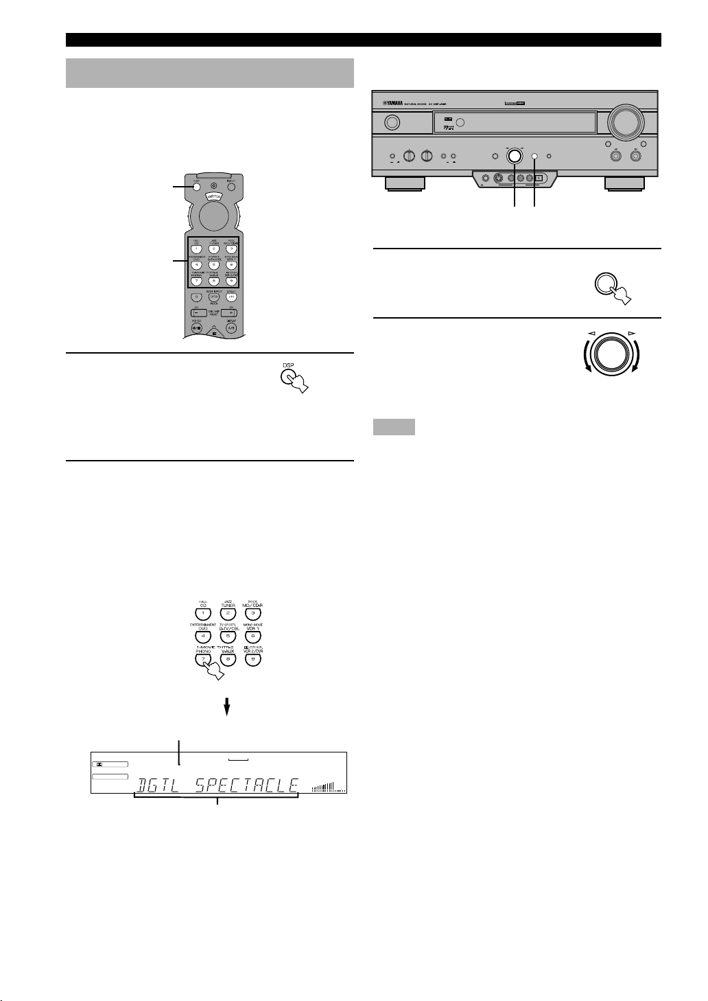
1 Press DSP.
The indicator lights up for
about 3 seconds.
y
• If the selector dial is set to the DSP/TUN position, skip this
step.
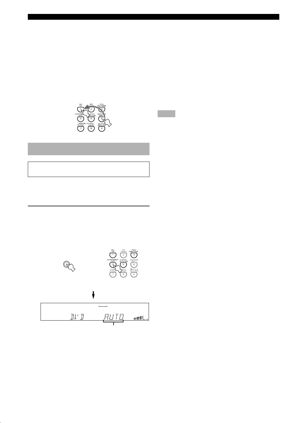
2 Use the numeric buttons to select the
desired program before the indicator goes
off.
• For example, to select the sub-program
“SPECTACLE”, press MOVIE THEATER 1
repeatedly.
• The name of the selected program appears on the
front panel display and on the video monitor.
Program group
DIGITAL
DSP
V-AUX
VCR2/DVR
D-TV/CBL
VCR 1
MOVIE THEATER 1
MD/CD-R
DVD
CDTUNER PHONO
VOLUME
■ On the front panel
DSP
PROGRAM
VOLUME
6CH INPUTINPUT MODE
INPUT
DIGITAL
– +
PHONES S VIDEO VIDEO L AUDIO R OPTICAL
SILENT VIDEO AUX
STANDBY
EXTENSION
/ON
BASS
BASS TREBLE SPEAKERS
– + – +
DIGITAL
SURROUND
AB
ONOFFON
OFF
2
1 Press DSP PROGRAM.
DSP
EFFECTSET MENU
PROGRAM
1
2 Turn the multi jog knob to
select the program.
The name of the selected
program appears on the front
panel display and on the video
monitor.
Notes
• Choose a DSP program based on your listening preference, and
not on the name of the program. The acoustics of your listening
room affect the DSP program. Minimize the sound reflections
in your room to maximize the effect created by the program.
• When you select an input source, this unit automatically selects
the last DSP program used with that source.
• When you set this unit in the standby mode, the current source
and DSP program are memorized and are automatically
selected when you turn on the power again.
• If a Dolby Digital or DTS signal is input when the input mode
is set to AUTO, the DSP program automatically switches to the
appropriate decoding program.
• When a monaural source is being played with PRO LOGIC/
NORMAL or PRO LOGIC/ENHANCED, no sound will be
heard from the main speakers and the rear speakers. Sound can
only be heard from the center speaker. However, if “1A
CENTER SP” on the SET MENU is set to NONE, the center
channel sound is output from the main speakers.
• When a source connected to the 6CH INPUT jacks of this unit
is selected, the digital sound field processor cannot be used.
• When 96-kHz sampling digital signals are input to this unit, the
DSP program cannot be selected. In this case, the sound is
reproduced as normal 2-channel stereo.
– +
28
Program name (sub-program)
Page 31

BASIC PLAYBACK
■ Virtual CINEMA DSP and SILENT
CINEMA
Virtual CINEMA DSP
Virtual CINEMA DSP allows you to enjoy the sound field
effects of the DSP program without rear speakers. Using
YAMAHA original technology, natural surround
reproduction is possible through the generation of a
virtual speaker.
The sound field processing is changed to the Virtual
CINEMA DSP mode by setting “1C REAR L/R SP” on
the SET MENU to NONE. Virtual CINEMA DSP is
performed by using the main speakers.
Note
• This unit is not set in the Virtual CINEMA DSP mode even if
“1C REAR L/R SP” is set to NONE in the following cases:
– when the 5CH STEREO, PRO LOGIC/NORMAL, DOLBY
DIGITAL/NORMAL or DTS/NORMAL program is selected;
– when the sound effect is turned off;
– when 6CH INPUT is selected as the input source;
– when 96-kHz sampling digital signals are input to this unit;
– when the Dolby Digital KARAOKE source is played;
– when using the test tone; or
– when connecting the headphones (you will hear SILENT
CINEMA).
SILENT CINEMA
SILENT CINEMA allows you to enjoy the realistic feel
of the DSP program while using headphones. This feature
delivers powerful surround reproduction just as if
listening through the speakers.
Normal Stereo Reproduction
Press EFFECT to turn off the sound effect
for normal stereo reproduction.
Press EFFECT again to turn the sound effect back
on.
EFFECT
Front panel
y
• If the selector dial is set to a position other than the DSP/TUN
position, first press DSP and then EFFECT on the remote
control.
Notes
• If you turn off the sound effect, no sound is output from the
center and rear speakers.
• If you turn off the sound effect while a Dolby Digital or DTS
signal is being output, the dynamic range of the signal is
automatically compressed and the sounds of the center and rear
speaker channels are mixed and output from the main speakers.
• The volume may be greatly reduced when you turn off the
sound effect or if you set “6 D-RANGE” on the SET MENU to
MIN. In this case turn on the sound effect.
or
Remote control
INTRODUCTION
PREPARATION
OPERATION
BASIC
OPERATION
ADVANCED
You can listen to SILENT CINEMA by connecting your
headphones to the PHONES jack while the effect
speakers are on.
INFORMATION
ADDITIONAL
APPENDIX
English
29
Page 32

BASIC RECORDING
Recording adjustments and other operations are
performed from the recording components. Refer to the
operation instructions for these components.
VOLUME
6CH INPUTINPUT MODE
INPUT
EXTENSION
STANDBY
/ON
BASS
BASS TREBLE SPEAKERS
–+–
+
DIGITAL
SURROUND
AB
ONOFFON
OFF
DIGITAL
PROGRAM
– +
PHONES S VIDEO VIDEO L AUDIO R OPTICAL
SILENT VIDEO AUX
DSP
EFFECTSET MENU
2
2
A/B/C/D/E
1 Turn on the power to the unit and all
connected component.
2 Select the source component you want to
record from.
INPUT
or
Front panel
Remote control
3 Start playback (or select a broadcast station)
on the source component.
4 Start recording on the recording component.
Notes
• Do a test recording before you start an actual recording.
• When this unit is set in the standby mode, you cannot record
between other components connected to this unit.
• The setting of BASS, TREBLE, BASS EXTENSION,
VOLUME, “2 L/R BALANCE” on the SET MENU and DSP
programs does not affect the recorded material.
• A source connected to the 6CH INPUT jacks of this unit cannot
be recorded.
• S-video and composite video signals pass independently
through this unit’s video circuits. Therefore, when recording or
dubbing video signals, if your video source component is
connected to provide only an S-video (or only a composite
video) signal, you can record only an S-video (or only a
composite video) signal by your VCR.
• A given input source is not output on the same REC OUT
channel. (For example, the signal input from VCR 1 IN is not
output on VCR 1 OUT.)
• Check the copyright laws in your country to record from
records, CDs, radio, etc. Recording of copyrighted material
may infringe copyright laws.
If you playback a video source that uses scrambled or
encoded signals to prevent it from being dubbed, the
picture itself may be disturbed due to those signals.
■ Special considerations when
recording DTS software
The DTS signal is a digital bitstream. Attempting to
digitally record the DTS bitstream will result in noise
being recorded. Therefore, if you want to use this unit to
record sources that have DTS signals recorded on them,
the following considerations and adjustments need to be
made.
For DVDs and CDs encoded with DTS
Only 2-channel analog audio signals may be recorded.
Set the DVD player (or CD player) as described in the
player’s operation instructions so that the audio signals
are output from the player’s analog outputs.
30
Page 33

ADVANCED OPERATION
SET MENU
The SET MENU consists of 10 items including the
speaker mode setting features. Use the SET MENU to
enjoy the optimum audio/video playback for your system.
y
• You can adjust the items on the SET MENU while playing a
source.
• We recommend that you adjust the items on the SET MENU
while using a video monitor. It is easier to see the video
monitor than it is to see the front panel display on this unit
while adjusting the items.
Note
• The indication on the front panel display is the abbreviation of
the OSD.
1 SPEAKER SET
1A CENTER SP
1B MAIN SP
1C REAR L/R SP
1D LFE/BASS OUT
1E MAIN LEVEL
2 L/R BALANCE
3 HP TONE CTRL
4 I/O ASSIGNMENT
4A CMPNT-V INPUT
4B OPTICAL OUT
4C OPTICAL IN
4D COAXIAL IN
5 INPUT MODE
6 DOLBY D. SET
LFE LEVEL
D-RANGE
7 DTS SET
8 SP DELAY TIME
9 DISPLAY SET
BLUE BACK
OSD SHIFT
DIMMER
10 MEMORY GUARD
Adjusting the Items on the SET MENU
Adjustment should be made with the remote control.
A/B/C/D/E
1
3,6
4,5
2
A/B/C/D/E
Notes
• Some items require extra steps to change to the desired setting.
• SET MENU and the multi jog knob on the front panel can also
be used to make these adjustments.
1 Set the selector dial to the
AMP/TUN (or DSP/TUN)
position.
2 Press SET MENU to enter the SET MENU.
SET MENU 1/3
1 SPEAKER SET
2 L/R BALANCE
3 HP TONE CTRL
4 I/O ASSIGNMENT
: Up/Down/
–/+ : Enter
3 Press u/d repeatedly to select the item (1 to
10) you want to adjust.
SET MENU 1/3
1 SPEAKER SET
2 L/R BALANCE
3 HP TONE CTRL
4 I/O ASSIGNMENT
: Up/Down/
–/+ : Enter
y
• By pressing SET MENU (or SET MENU on the front panel)
repeatedly, you can select items in the same order as when
pressing d.
INTRODUCTION
PREPARATION
OPERAIONT
BASIC
OPERATION
ADVANCED
INFORMATION
ADDITIONAL
APPENDIX
English
31
Page 34

SET MENU
1A CENTER SP
LRG
SML
NONE
4 Press j or i once to enter the setup mode of
the selected item.
The last setting you adjusted appears on the video
monitor or on the front panel display.
4A CMPNT-V INPUT
[A] • • • • • DVD
[B] • • • • • D-TV/CBL
y
• When making adjustments through the front panel, turn the
multi jog knob one step to either the left or the right to enter
setup mode for the selected item.
Depending on the item, press u/d to select a sub
item.
4B OPTICAL OUT
(1) • • • • • MD/CD-R
y
• When making adjustments through the front panel, press SET
MENU.
5 Press j / i repeatedly to change the setting
of the item.
4A CMPNT-V INPUT
[A] • • • • • VCR 1
[B] • • • • • D-TV/CBL
y
• When making adjustments through the front panel, turn the
multi jog knob to change the settings.
6 Press u/d repeatedly until the current DSP
program appears or simply press one of the
DSP program group button to exit from the
SET MENU.
Memory back-up
The memory back-up circuit prevents the stored data
from being lost even if this unit is set in the standby
mode, the power cord is disconnected from the AC
outlet, or the power supply is temporarily cut due to
power failure. However, if the power is cut for more
than one week, the settings of the SET MENU you
adjusted will return to the factory settings. If so, adjust
the items again.
1 SPEAKER SET (speaker mode
settings)
Use this feature to select suitable output modes for your
speaker configuration.
Notes
• When 96-kHz sampling digital signals are input to this unit,
level adjustments in items 1B, 1D and 1E are possible, but
those in items 1A, 1C are not affected.
• When 6CH INPUT is selected as the input source, level
adjustments in items 1A through 1E are not affected.
■ 1A CENTER SP (center speaker
mode)
By adding a center speaker to your speaker configuration,
the unit can provide good dialog localization for many
listeners and superior synchronization of sound and
images. The OSD shows a large, small or no center
speaker depending on how you set this item.
Choices: LRG (large), SML (small), NONE
Initial setting: LRG
LRG
Select this if you have a large center speaker. The entire
range of the center channel signal is directed to the center
speaker.
1A CENTER SP
or
y
• When operating through the front panel, press SET MENU
repeatedly until the DSP program name appears to exit from the
SET MENU.
32
SML
LRG
SML
Select this if you have a small center speaker. The lowfrequency signals (90 Hz and below) of the center
channel are directed to the speakers selected with “1D
LFE/BASS OUT”.
NONE
Page 35

SET MENU
1C REAR L/R SP
LRG
SML
NONE
1C REAR L/R SP
LRG
SML
NONE
1C REAR L/R SP
LRG
SML
NONE
NONE
Select this if you do not have a center speaker. All of the
center channel signals are directed to the left and right
main speakers.
1A CENTER SP
SML
LRG
NONE
■ 1B MAIN SP (main speaker mode)
The OSD shows large or small main speakers depending
on how you set this item.
Choices: LARGE, SMALL
Initial setting: LARGE
LARGE
Select this if you have large main speakers. The entire
range of the left and right main channel signal is directed
to the left and right main speakers.
1B MAIN SP
■ 1C REAR L/R SP (rear speaker
mode)
The OSD shows large, small or no rear speakers
depending on how you set this item.
Choices: LRG (large), SML (small), NONE
Initial setting: LRG
LRG
Select this if you have large left and right rear speakers or
if a rear subwoofer is connected to the rear speakers. The
entire range of the rear channel signal is directed to the
left and right rear speakers.
SML
Select this if you have small left and right rear speakers.
The low-frequency signals (90 Hz and below) of the rear
channel are directed to the speakers selected with “1D
LFE/BASS OUT”.
INTRODUCTION
PREPARATION
BASIC OPERA-
TION
LARGE
SMALL
SMALL
Select this if you have small main speakers. The lowfrequency signals (90 Hz and below) of the main channel
are directed to the speakers selected with “1D LFE/BASS
OUT”.
1B MAIN SP
LARGE
Note
• When you select MAIN for “1D LFE/BASS OUT”, the lowfrequency signals (90 Hz and below) of the main channel are
directed to the main speakers even if you select SMALL for the
main speaker mode.
SMALL
NONE
Select this if you do not have rear speakers.
y
• This unit is set in the Virtual CINEMA DSP mode by selecting
NONE for “1C REAR L/R SP”.
OPERATION
ADVANCED
INFORMATION
ADDITIONAL
APPENDIX
English
33
Page 36

SET MENU
1E MAIN LEVEL
Normal
–10dB
1E MAIN LEVEL
Normal
–10dB
■ 1D LFE/BASS OUT (bass out
mode)
LFE signals carry low-frequency effects when this unit
decodes a Dolby Digital or DTS signal. Low-frequency
signals are defined as 90 Hz and below.
Choices: SWFR (subwoofer), MAIN, BOTH
Initial setting: BOTH
SWFR
Select this if you use a subwoofer. The LFE signals are
directed to the subwoofer.
1D LFE/BASS OUT
MAIN
SWFR
MAIN
Select this if you do not use a subwoofer. The LFE
signals are directed to the main speakers.
1D LFE/BASS OUT
BOTH
■ 1E MAIN LEVEL (main level
mode)
Change this setting if you cannot match the output level
of the center and rear speakers with the main speakers
because of the unusually high-efficiency performance of
the main speakers.
Choices: Normal, –10 dB
Initial setting: Normal
Normal
Normally select this setting.
–10 dB
Select this if you cannot match the output level of your
effect speakers with that of your main speakers when
using the test tone. This setting decreases the main
speaker output level to about one-third of the normal
level.
MAIN
SWFR
BOTH
BOTH
Select this if you use a subwoofer and you want to mix
the main channel low-frequency signals with the LFE
signals.
1D LFE/BASS OUT
MAIN
SWFR
Notes
• When playing a 2-channel source (CD, MD, tape, video
cassette etc.), select the BOTH position to direct low bass
signals (below 90 Hz) to the SUBWOOFER jack.
• When you select SMALL (SML) for items 1A, 1B and 1C, the
low-frequency signals (90 Hz and below) from those channels
are added to the LFE and output to the subwoofer.
BOTH
2 L/R BALANCE (balance of the
left and right main speakers)
Use this feature to adjust the balance of the output level
from the left and right main speakers.
Control range: 10 for L/R
Initial setting: 0
Press i to decrease the output level for the
left main speaker. Press j for the right main
speaker.
2 L/R BALANCE
• • • • • • • • • •
L
Note
• The L/R BALANCE setting also applies to when headphones
are being used.
• • • • • • • • • •
I I
0
–/+ : Adjust
: Exit/
R
34
Page 37

SET MENU
3 HP TONE CTRL (headphone
tone control)
Use this feature to adjust the level of the bass and treble
when you use your headphones.
Control range (dB): –6 to +3
Initial setting: 0 dB for both BASS and TRBL (treble)
3 HP TONE CTRL
BASS
TRBL
–
0dB
+
4 I/O ASSIGNMENT
It is possible to assign jacks according to the component
to be used if this unit’s COMPONENT VIDEO input jack
or DIGITAL INPUT/OUTPUT jack settings (component
names for jacks) differ from that component. This makes
it possible to change the jack assignment and effectively
connect more component.
Once you assign, you can select that component with
INPUT l / h (or the input selector buttons).
■ 4C OPTICAL IN (for the OPTICAL
INPUT jacks)
Initial settings: (2) MD/CD-R
(3) DVD
(4) D-TV/CBL
4C OPTICAL IN
(2) • • • • • MD/CD-R
(3) • • • • • DVD
(4) • • • • • D-TV/CBL
■ 4D COAXIAL IN (for the COAXIAL
INPUT jack)
Initial setting: (5) CD
4D COAXIAL IN
(5) • • • • • CD
Note
• You cannot select an item more than once for the same type of
jack.
INTRODUCTION
PREPARATION
BASIC OPERA-
TION
■ 4A CMPNT-V INPUT (for the
COMPONENT VIDEO jacks)
Initial settings: [A] DVD
[B] D-TV/CBL
4A CMPNT-V INPUT
[A] • • • • • DVD
[B] • • • • • D-TV/CBL
■ 4B OPTICAL OUT (for the
OPTICAL OUTPUT jack)
Initial setting: (1) MD/CD-R
4B OPTICAL OUT
(1) • • • • • MD/CD-R
5 INPUT MODE (initial input
mode)
Use this feature to designate the input mode when turning
on the power of this unit with the source component
connected to more than one type of input jacks.
Choices: AUTO, LAST
Initial setting: AUTO
5 INPUT MODE
AUTO LAST
–/+ : Select
/
: Exit
AUTO
Select this to allow this unit to automatically detect the
type of input signal and select the appropriate input mode.
LAST
Select this to set this unit to automatically select the last
input mode used for that source.
OPERATION
ADVANCED
INFORMATION
ADDITIONAL
APPENDIX
English
35
Page 38

SET MENU
6 DOLBY D. SET (Dolby Digital
set)
This setting is effective only when this unit decodes
Dolby Digital signals.
6 DOLBY D. SET
LFE LEVEL
D-RANGE
■ LFE LEVEL
Use this feature to adjust the output level of the LFE
(low-frequency effect) channel when playing back a
Dolby Digital signal. The LFE signal carries the lowfrequency special effect sound which is only added to
certain scenes.
Control value (dB): –20 to 0
Initial setting: 0 dB
Notes
• Adjust the LFE level according to the capacity of your
subwoofer.
• Normally, around –6 dB to –8 dB is most suitable for listening
at home.
• • • •
• • •
MAX STD MIN
–/+ : Adjust
: Select/
0dB
MAX
Dialog
level
Output level
Input level
MIN
Dialog
level
Input level
Dialog
level
1.0
Output level
L-LEVEL BST
STD
H-LEVEL CUT
0.0
Input level
0.0
1.0
Output level
Note
• When you select MIN, the sound output may be faint because
some Dolby Digital signals are not compatible with the
minimum-level dynamic range. In this case, select MAX or
STD.
7 DTS SET (DTS LFE level)
This setting is effective only when this unit decodes DTS
signals.
■ D-RANGE (dynamic range)
Use this feature to adjust the dynamic range (the
difference between the maximum level and the minimum
level of sounds).
Choices: MAX, STD (standard), MIN
Initial setting: MAX
• Select MAX for feature films.
• Select STD for general use.
• Select MIN for listening to sources at an extremely
low volume level.
Use this feature to adjust the output level of the LFE
(low-frequency effect) channel when playing back a DTS
signal. The LFE signal carries the low-frequency special
effect sound which is only added to certain scenes.
Control range (dB): –10 to +10
Initial setting: 0 dB
7 DTS SET
LFE LEVEL • • • • 0dB
–/+ : Adjust
: Exit/
Note
• Adjust the LFE level according to the capacity of your
subwoofer.
36
Page 39

SET MENU
8 SP DELAY TIME
Use this feature to adjust the delay of the center channel
sound. This feature works when this unit decodes a Dolby
Digital or DTS signal. Ideally, the center speaker should
be the same distance from the listening position as the left
and right main speakers. However, in most home
situations, the center speaker is placed in line with the
main speakers. By delaying the sound from the center
speaker, the apparent distance from the center speaker to
the listening position can be adjusted to make it seem the
same as the distance between the left and right main
speakers to the listening position. Adjusting the delay
time for the center speaker is especially important for
giving depth to the dialog.
Control range (ms): 0 to 5
Initial setting: 0 ms
8 SP DELAY TIME
CENTER • • • • • • 0ms
–/+ : Adjust
: Exit/
Center speaker image
C
L
R
C
9 DISPLAY SET
9 DISPLAY SET
BLUE BACK • • • AUTO
OSD SHIFT • • • • • • 0
DIMMER • • • • • • • • • • 0
■ BLUE BACK
Selecting AUTO for the on-screen display setting displays
a blue background when there’s no video signal input.
Nothing is displayed on the screen including the onscreen display if OFF is selected.
Initial setting: AUTO
■ OSD SHIFT (OSD off-set position)
This setting is used to adjust the vertical position of the
OSD.
Control range: +5 (downward) to –5 (upward)
Initial setting: 0
Press i to lower the position of the OSD.
Press j to raise the position of the OSD.
■ DIMMER
You can adjust the brightness of the front panel display.
Control range: –4 to 0
Initial setting: 0
INTRODUCTION
PREPARATION
BASIC OPERA-
TION
OPERATION
ADVANCED
RL
RR
y
• Increasing the delay by 1 ms simulates moving the speaker
about 30 cm (one foot) farther away from the actual position of
the center speaker.
10 MEMORY GUARD
Use this feature to prevent accidental changes to DSP
program parameter values and other settings on this unit.
Choices: ON, OFF
Initial setting: OFF
10 MEMORY GUARD
OFF ON
–/+ : Select
/
: Exit
Select ON to protect the following features:
• DSP program parameters
• All SET MENU items
• Center, rear speakers and subwoofer levels
• The on-screen display (OSD) mode
Notes
• When “10 MEMORY GUARD” is set to ON, you cannot use
the test tone.
• When “10 MEMORY GUARD” is set to ON, you cannot select
any other SET MENU items.
INFORMATION
ADDITIONAL
APPENDIX
English
37
Page 40

ADJUSTING THE LEVEL OF THE EFFECT SPEAKERS
You can adjust the output level of each effect speaker
(center, left and right rear and subwoofer) while listening
to a music source.
Adjustment should be made with the remote control.
A/B/C/D/E
1
3
2
A/B/C/D/E
1 Set the selector dial to the
AMP/TUN (or DSP/TUN)
position.
2 Press LEVEL repeatedly to select the
speaker(s) you want to adjust.
Each time you press LEVEL, the selected speaker
changes and appears on the front panel display and
on the video monitor as follows: center, right rear,
left rear and subwoofer.
3 Press j / i to adjust the speaker output level.
• The control range for the center or left and right
rear speakers is from +10 dB to –10 dB.
• The control range for the subwoofer is from 0 dB
to –20 dB.
Notes
• If the speaker output mode is set to NONE, the output level of
that speaker cannot be adjusted.
• When you adjust the output level with LEVEL, the settings you
made with the test tone will be changed.
• To adjust speakers other than the subwoofer, the adjusting
procedure using the test tone on page 22 is recommended.
Memory back-up
The memory back-up circuit prevents the stored data
from being lost even if this unit is set in the standby
mode, the power cord is disconnected from the AC
outlet, or the power supply is temporarily cut due to
power failure. However, if the power is cut for more
than one week, the output level of the effect speakers
you adjusted will return to the factory settings. If so,
adjust the output level again.
CENTER
R SUR.
L SUR.
SWFR
Center speaker output level
Right rear speaker output
level
Left rear speaker output
level
Subwoofer output level
y
• Once you press LEVEL, you can also select the speaker(s) to
be adjusted by pressing d. (Pressing u changes the selection
in the reverse order.)
38
Page 41

SLEEP TIMER
Use this feature to automatically set this unit in the
standby mode after the amount of time you have set. The
sleep timer is useful when you are going to sleep while
this unit is playing or recording a source. The sleep timer
also automatically turns off the external components
connected to AC OUTLET(S).
The sleep timer can only be set with the remote control.
Setting the Sleep Timer
A/B/C/D/E
2
3
A/B/C/D/E
1 Select a source and start playback on the
source component.
2 Set the selector dial to a
position other than the TV
position.
3 Press SLEEP repeatedly
to set the amount of time
before this unit
automatically turns off.
Each time you press SLEEP, the front panel display
changes as shown below.
120 90 60 30
4 The “SLEEP” indicator soon lights up on the
front panel display after the sleep timer has
been set.
The display then returns to the previous indication.
MD/CD-R
DVD
D-TV/CBL
VCR 1
VCR2/DVR
V-AUX
DIGITAL
DSP
CDTUNER PHONO
SLEEP
VOLUME
Canceling the Sleep Timer
Press SLEEP repeatedly until “SLEEP OFF”
appears on the front panel display.
After a few seconds, “SLEEP OFF” disappears, the
“SLEEP” indicator goes off and the display returns
to the previous indication.
y
• The sleep timer setting can also be canceled by setting this unit
in the standby mode by using STANDBY on the remote
control (or STANDBY/ON on the front panel) or by
disconnecting the AC power cord from the AC outlet.
INTRODUCTION
PREPARATION
OPERAIONT
BASIC
OPERATION
ADVANCED
INFORMATION
ADDITIONAL
DIGITAL
DSP
The SLEEP timer is off
(SLEEP OFF).
(This is the state before
SLEEP is pressed.)
D-TV/CBL
VCR 1
VCR2/DVR
V-AUX
MD/CD-R
DVD
CDTUNER PHONO
SLEEP
VOLUME
APPENDIX
English
39
Page 42

REMOTE CONTROL FEATURES
It is possible to control this unit and other YAMAHA A/V components using the remote control supplied with this unit.
It is also possible to control components from other manufacturers (or some YAMAHA components) by setting the
proper manufacturer code (a signal assigned to each manufacturer and component).
Note
• For the notes on batteries, operating distance and names and functions of the remote control, refer to each description in this manual.
Selector Dial
Select the component (position) to be controlled by the remote control. For example, if the CD position is selected, the
remote control is set in the CD operation mode, allowing the CD player to be controlled. When turning the selector dial,
the position changes as follows:
AMP/TUN
You can perform the basic operations
of this unit.
CD
The code for a YAMAHA CD
player is factory-set.
CBL/SAT
A cable TV or satellite tuner can be controlled.
VCR
A VCR can be controlled.
TV
A TV can be controlled.
Selector
dial
TAPE/MD
The code for a YAMAHA MD recoder is factoryset. Be sure to set the proper code when
operating a CD recorder or tape deck.
DVD/LD & DVD MENU
An LD player can be controlled in
the DVD/LD position. A DVD player
can be controlled in the DVD/LD
and DVD MENU positions. The
code for a YAMAHA DVD player is
factory-set.
DSP/TUN
This unit can be controlled and DSP
programs can be selected directly.
Notes
• The general operational buttons on the remote control differ depending on the position of the selector dial. See the following pages
for details.
• When shipped from the factory, the YAMAHA manufacturer codes listed on page 46 are set for each dial position. If unable to
operate your YAMAHA A/V component, please try using another YAMAHA code.
40
Page 43

REMOTE CONTROL FEATURES
Commonly Used Buttons in Any Position of the Selector Dial
Regardless of the position of the selector dial, you can
control this unit and your TV with the following buttons.
Note
• You have to set up the code for your TV in the TV position
before you can control the TV.
1
!
@
#
■ Controlling this unit
See “Remote Control”.
1 STANDBY
2 POWER
3 VOLUME +/–
4 SLEEP
Note
• If you have set up the code for your TV and set the selector dial
to the TV position, this button is used to set the sleep timer for
the TV.
5 MUTE
Note
• If you have set up the code for your TV and set the selector dial
to the TV position, this button is used to mute the TV sound.
2
3
4
5
Controlling the Components Connected to This Unit
The example below describes the procedure for
controlling a YAMAHA CD player.
A/B/C/D/E
1
5
3
4
2
6
A/B/C/D/E
1 Set the selector dial to the
CD position.
2 Turn on the power.
3 Press INPUT.
The indicator lights up for
about 3 seconds.
4 Press CD while the
indicator is lit.
5 Press p.
See “Button Names and
Functions in Eash Position”
for the CD player operation
buttons.
6 Adjust the volume.
INTRODUCTION
PREPARATION
OPERAIONT
BASIC
OPERATION
ADVANCED
INFORMATION
ADDITIONAL
■ Controlling your TV
! TV POWER
@ TV INPUT
# TV VOLUME +/–
If you set the remote control with the manufacturer
codes listed from page i at the end of this
manual, you can control other brands of components.
See “Setting the Manufacturer Codes” for details.
APPENDIX
English
41
Page 44

REMOTE CONTROL FEATURES
Button Names and Functions in Each Position
■ TAPE/MD position (tape deck, MD recorder or CD recorder)
Select the TAPE/MD position.
Numeric buttons (MD/CD-R)
INDEX (CD-R)
+10 (MD/CD-R)
Deck A/B (tape)
r Rec/Pause (tape/MD)
e Pause (MD/CD-R)
b DIR A (tape)
This button selects the playing direction of deck A.
Skip – (MD/CD-R)
w Rewind (tape)
Search (MD/CD-R)
AV POWER
This button turns on the tape deck, MD recorder or CD recorder that has a remote control with a power button if you have set up the code for
another manufacturer.
p Play
A/B/C/D/E
This button selects deck A or B on a double-cassette
tape deck.
DISPLAY (MD/CD-R)
a DIR B (tape)
This button selects the playing direction of
deck B.
Skip + (MD/CD-R)
s Stop
f Fast forward (tape)
Search (MD/CD-R)
■ CD position
(for a CD player with CD changer)
Select the CD position.
DISC SKIP –/+
p Play
b Skip –
w Search
A/B/C/D/E
Numeric buttons
INDEX
+10
y Pause/Stop function
• Press the button once to give a
pause in operation and press
DISPLAY
e Pause
YAMAHA CD player (factory settings): Pause/Stop
a Skip +
s Stop
YAMAHA CD player (factory settings): Pause/Stop
f Search
AV POWER
This button turns on the CD player that has a remote
control with a power button if you have set up the
code for another manufacturer.
once more to stop operation.
• The dark-shaded buttons do not function even if you have set up the manufacturer code.
• Some of them may not function depending on the component you have. In this case, use the original remote
control supplied with your component.
42
Page 45

REMOTE CONTROL FEATURES
■ DVD/LD position
Select the DVD/LD position.
Numeric buttons
INDEX/Time (DVD)
Chapter/Time (LD)
+10
DISC SKIP –/+ (DVD)
p Play
b Skip – (DVD)
Skip/Chapter – (LD)
w Search
AV POWER
(DVD) This button turns on the DVD player that has a remote control with a power button if you have set up the code for another manufacturer.
(LD) This button turns on the LD player that has a remote control with a power button if you have set up the code for another manufacturer.
A/B/C/D/E
DISPLAY
e Pause
a Skip + (DVD)
Skip/Chapter + (LD)
s Stop
f Search
INTRODUCTION
PREPARATION
OPERAIONT
BASIC
■ DVD MENU position
Note
• DVD MENU operations cannot be performed for some DVD players.
Select the DVD MENU position.
DISC SKIP –/+
Return
Menu select
Menu left
TITLE
AV POWER
This button turns on the DVD player that has a remote control with a power button if you have set up
the code for another manufacturer.
A/B/C/D/E
Numeric buttons
INDEX
+10
DISPLAY
Menu up
Menu right
Menu down
MENU
OPERATION
ADVANCED
INFORMATION
ADDITIONAL
APPENDIX
• The dark-shaded buttons do not function even if you have set up the manufacturer code.
• Some of them may not function depending on the component you have. In this case, use the original remote
control supplied with your component.
English
43
Page 46

REMOTE CONTROL FEATURES
■ VCR position
Select the VCR
position.
VCR REC
Press this button
twice to start
recording.
p Play
w Rewind
AV POWER
This button turns on a VCR that has a remote control with a power
button if you have set up the code for your VCR.
A/B/C/D/E
Numeric
buttons
Ch enter/Recall
_/_ _
CH –/+
DISPLAY
e Pause
s Stop
f
Fast forward
■ CBL/SAT position
Select the CBL/SAT
position.
Menu select
Menu left
AV POWER
This button turns on a cable TV/satellite tuner that has a remote
control with a power button if you have set up the code for your cable
TV/satellite tuner.
■ TV position
Note
• You can control your VCR if you have set up the code for it in the VCR position.
CH –/+
Recall
A/B/C/D/E
Numeric buttons
Ch enter
_/_ _
DISPLAY/
Guide (SAT)
Menu up
Menu right
Menu down
MENU
Select the TV
position.
Numeric buttons
Press this button twice.
TV POWER
This button turns on a TV that has a
remote control with a power button if
you have set up the code for your TV.
VCR REC
p VCR play
w VCR rewind
TV VOL +/–
TV INPUT
A/B/C/D/E
Ch enter/Recall
_/_ _
CH –/+
DISPLAY
e VCR pause
s VCR stop
f
VCR fast forward
VCR power
TV SLEEP
TV MUTE
• The dark-shaded buttons do not function even if you have set up the manufacturer code.
• Some of them may not function depending on the component you have. In this case, use the original remote
control supplied with your component.
44
Page 47

REMOTE CONTROL FEATURES
Setting the Manufacturer Code
You can set up the code for the manufacturer of your
component in each position of the selector dial.
1 Turn on your component to be used.
2 Set the selector dial to the
desired position for the
component (TAPE/MD, CD,
DVD/LD, etc.).
3 Press j / i at the same time for about
4 seconds.
The indicator flashes twice.
4 Use the numeric buttons
to enter the four-digit
manufacturer code for the
component to be used.
Make sure that the
indicator flashes twice.
If the indicator does not flash
or flashes rapidly several
times, repeat step 3 and reenter the code.
5 Press AV POWER (or any other button) to
check if you have set up the code correctly.
If your component cannot be
controlled with the remote
control, try setting another
code for the same
manufacturer.
Notes
• You can set up only one code for one position.
• In the DVD/LD and DVD MENU positions:
Be sure to set the selector dial to the DVD/LD position before
entering the code for the DVD/LD player. You cannot set up
the code for a DVD player when the selector dial is set to the
DVD MENU position. The code set up in the DVD/LD
position is also simultaneously set up in the DVD MENU
position.
• If your component does not respond to any of the codes listed
for the manufacturer, use the original remote control supplied
with your component.
■ To use a second (and third) VCR
You can control a second (and third) VCR in the CBL/
SAT and DVD MENU positions if a cable TV/satellite
tuner or DVD player is not being used.
Note
• In order to set a second (and third) VCR in the DVD MENU
position, it is necessary to first set up the code for an LD player
in the DVD/LD position.
1 Turn on the VCR to be used.
2 Set the selector dial to the
CBL/SAT or DVD MENU
position.
3 Press j / i at the same time for about
4 seconds.
The indicator flashes twice.
4 Use the numeric buttons
to enter the four-digit
code for the second (and
third) VCR. Make sure that
the indicator flashes
twice.
If the indicator does not flash
or flashes rapidly several
times, repeat step 3 and reenter the code.
5 Press AV POWER (or any other button) to
check if you have set up the code correctly.
If the VCR cannot be
controlled with the remote
control, try setting another
code for the same
manufacturer.
INTRODUCTION
PREPARATION
OPERAIONT
BASIC
OPERATION
ADVANCED
INFORMATION
ADDITIONAL
APPENDIX
45
English
Page 48

REMOTE CONTROL FEATURES
Returning to the Factory Setting
■ To return to the factory-set codes
in all positions
1 Press j / i at the same time for about
4 seconds.
The indicator flashes twice.
■ To return to the factory-set codes
in each position
1 Set the selector dial to the
position for the
component to be returned
to the factory setting.
2 Press j / i at the same time for about
4 seconds.
The indicator flashes twice.
2 Enter the code number “9990”.
Make sure that the indicator flashes twice.
3 Enter the code number “0000”.
Make sure that the indicator flashes twice.
The following codes are factory set.
Selector dial position Component Code Set component Set code
TV TV 0101
CBL/SAT Satellite tuner 0006
VCR VCR 0002
DVD/LD DVD player 0008 (YAMAHA DVD player)
CD CD player 0005 (YAMAHA CD player)
TAPE/MD MD recorder 0024 (YAMAHA MD recorder)
We recommend that you write all the code numbers you have set on the table above.
46
Page 49

ADDITIONAL INFORMATION
SOUND FIELD PROGRAM
A digital sound field processor (DSP) based on the latest YAMAHA technology is built into this unit. It is possible to
play back various sound fields for the source you are listening to.
Note
• Regardless of the program name and characteristics listed in the table below, select the sound field program that sounds best to you.
Hi-Fi DSP Programs
■ For audio sources: Nos. 1 to 4
No. Program (group) Sub-program Features
1 CONCERT HALL —
2 JAZZ CLUB — This is the sound field at stage front in “The Bottom Line”, a famous New York
3 ROCK CONCERT —
4 ENTERTAINMENT DISCO
5CH STEREO
A large round concert hall with a rich surround effect. Pronounced reflections
from all directions emphasize the extension of sounds. The sound field has a great
deal of presence, and your virtual seat is near the center, close to the stage.
jazz club. The floor can seat 300 people to the left and right in a sound field
offering a real and vibrant sound.
The ideal program for lively, dynamic rock music. The data for this program was
recorded at LA’s “hottest” rock club. The listener’s virtual seat is at the center-left
of the hall.
This program recreates the acoustic environment of a lively disco in the heart of a
big city. The sound is dense and highly concentrated. It is also characterized by a
high-energy, “immediate” sound.
Using this program increases the listening position range. This is a sound field
suitable for background music at parties.
INTRODUCTION
PREPARATION
BASIC OPERA-
TION
OPERATION
ADVANCED
Note
• Reverberations (sound effects) for realizing the sound field and unprocessed stereo from the left and right main speakers is output.
The sound is not output from the center speaker. (The sound is output when one of these programs is selected while playing a source
encoded with a Dolby Digital or DTS signal. If 5CH STEREO is selected, the sound is output from all speakers regardless of the
input source.)
CINEMA DSP Programs
■ For audio-video sources: Nos. 4 to 6
No. Program (group) Sub-program Features
4 ENTERTAINMENT GAME
5 TV SPORTS — Although the presence sound field is relatively narrow, the surround sound field
6 MONO MOVIE —
This program adds a deep and spatial feeling to video game sounds.
employs the sound environment of a large concert hall. With this program, you
can enjoy watching various TV programs such as news, variety shows, music
programs or sports programs. In a stereo broadcast of a sports game, the
commentator is oriented at the center position, and the shouts and the
atmosphere in the stadium spread on the surround side, while their spread to the
rear is properly restrained.
This program is provided for reproducing monaural video sources (such as old
movies). The program produces the optimum reverberation to create sound depth
by using only the presence sound field.
INFORMATION
ADDITIONAL
APPENDIX
English
47
Page 50

SOUND FIELD PROGRAM
■ For movie programs: Nos. 7 to 9
Program
No.
(group)
MOVIE
7
THEATER 1
8 MOVIE
THEATER 2
9
q/DTS
SURROUND
SPECTACLE 70 mm
SCI-FI 70 mm SCI-FI
ADVENTURE 70 mm
GENERAL 70 mm GENERAL Analog, PCM,
NORMAL PRO LOGIC/
ENHANCED PRO LOGIC/
Sub-program
SPECTACLE
DGTL
SPECTACLE
DTS SPECTACLE
DGTL SCI-FI Dolby Digital
DTS SCI-FI
ADVENTURE
DGTL
ADVENTURE
DTS ADVENTURE
DGTL GENERAL
DTS GENERAL
NORMAL
DOLBY DIGITAL/
NORMAL
DTS DIGITAL
SUR./NORMAL
ENHANCED
DOLBY DIGITAL/
ENHANCED
DTS DIGITAL
SUR./ENHANCED
Input source Features
Analog, PCM,
Dolby Digital in
2-channel
Dolby Digital
(5.1-channel)
DTS
Analog, PCM,
Dolby Digital in
2-channel
(5.1-channel)
DTS
Analog, PCM,
Dolby Digital in
2-channel
Dolby Digital
(5.1-channel)
DTS
Dolby Digital in
2-channel
Dolby Digital
(5.1-channel)
DTS
Analog, PCM,
Dolby Digital in
2-channel
Dolby Digital
(5.1-channel)
DTS
Analog, PCM,
Dolby Digital in
2-channel
Dolby Digital
(5.1-channel)
DTS
This program creates the extremely wide sound
field of a 70-mm movie theater. It precisely
reproduces the source sound in detail, making
both the video and the sound field incredibly real.
This is ideal for any kind of video source encoded
with Dolby Surround, Dolby Digital or DTS
(especially large-scale movie productions).
This program clearly reproduces dialog and
sound effects in the latest sound form of science
fiction films, thus creating a broad and expansive
cinematic space amid the silence. You can enjoy
science fiction films in a virtual-space sound field
that includes Dolby Surround, Dolby Digital and
DTS-encoded software employing the most
advanced techniques.
This program is ideal for precisely reproducing
the sound design of the newest 70-mm and
multichannel soundtrack films. The sound field
is made to be similar to that of the newest movie
theaters, so the reverberations of the sound field
itself are restrained as much as possible.
This program is for reproducing sounds from
70-mm and multichannel soundtrack films, and
is characterized by a soft and extensive sound
field. The presence sound field is relatively
narrow. It spatially spreads all around and toward
the screen, restraining the echo effect of
conversations without losing clarity. For the
surround sound field, the harmony of music or
chorus sounds beautifully in a wide space at the
rear of the sound field.
The built-in decoder precisely reproduces sounds
and sound effects from sources.
The highly efficient decoding process improves
crosstalk and channel separation, and makes
sound positioning smoother and more precise.
In this program, the digital sound field processor
is not turned on.
This program ideally simulates the multisurround speaker systems of the 35-mm film
theaters. Dolby Pro Logic decoding, Dolby
Digital decoding or DTS decoding and digital
sound field processing create precise effects
without altering the original sound orientation.
The surround effects produced by this sound field
wrap around the viewer naturally from the back to
the left and right, and toward the screen.
Notes
• The “ x ” indicator does not light up when selecting the sub-program “NORMAL” of the q/DTS SURROUND program.
• If “1A CENTER SP” on the SET MENU is set to NONE, no sound is output from the center speaker.
• The effect sound is output from the main speakers when a monaural source is played with CINEMA DSP program groups 4 (GAME)
and 5 to 8.
48
Page 51

SOUND FIELD PROGRAM
■ MOVIE THEATER 1 and 2
Most commercially available movie software has 4-channel (left, center, right and surround) sound information encoded
by Dolby Surround matrix processing and stored on the left and right tracks. These signals are processed by the Dolby
Pro Logic decoder. The MOVIE THEATER programs are designed to recreate the spaciousness and delicate nuances of
sound that tend to be lost in the encoding and decoding processes.
The 6-channel soundtracks found on 70-mm film produce precise sound field localization and rich, deep sound without
using matrix processing. This unit’s MOVIE THEATER 70 mm programs provide the same quality of sound and sound
localization that 6-channel soundtracks do.
When the input source is analog, PCM or encoded with Dolby Digital in 2-channel
Presence DSP
sound field
Surround DSP
sound field
These programs express an immense sound field and a
large surround effect. They also give depth to the sound
from the main speakers to recreate the realistic sound of a
Dolby Stereo theater.
70 mm SPECTACLE
70 mm SCI-FI
70 mm ADVENTURE
70 mm GENERAL
INTRODUCTION
PREPARATION
BASIC OPERA-
The built-in Dolby Digital or DTS decoder brings the professional-quality sound designed for movie theaters into your
home. With the unit’s MOVIE THEATER programs, you can recreate a dynamic sound that gives you the feeling of
being at a public theater in your listening room by using Dolby Digital or DTS technology.
When the input source is encoded with Dolby Digital (5.1-channel) or DTS (Tri-Field CINEMA DSP)
These programs use YAMAHA’s tri-field DSP processing
on each of the Dolby Digital or DTS signals for the front,
left surround and right surround channels. This
processing enables this unit to reproduce the immense
Presence DSP
sound field
sound field and surround expression of a Dolby Digitalor DTS-equipped movie theater without sacrificing the
clear separation of all channels.
DGTL SPECTACLE
DTS SPECTACLE
DGTL SCI-FI
DTS SCI-FI
Left surround DSP
sound field
Right surround DSP
sound field
DGTL ADVENTURE
DTS ADVENTURE
DGTL GENERAL
DTS GENERAL
y
• If a Dolby Digital signal or DTS signal is input when the input mode is set to AUTO, the DSP program will be automatically
switched to the Dolby Digital playback sound field or DTS playback sound field.
TION
OPERATION
ADVANCED
INFORMATION
ADDITIONAL
APPENDIX
49
English
Page 52

SOUND FIELD PROGRAM PARAMETER EDITING
What is a sound field?
What really creates the rich, full tones of a live instrument
are the multiple reflections from the walls of the room. In
addition to making the sound “live”, these reflections
enable us to tell where the player is situated, and the size
and shape of the room in which we are sitting.
■ Elements of a sound field
In any environment, in addition to the direct sound
coming straight to our ears from the player’s instrument,
there are two distinct types of sound reflections that
combine to make up the sound field:
Early reflections
Reflected sounds reach our ears extremely rapidly
(50 ms – 100 ms after the direct sound), after reflecting
from one surface only — for example, from the ceiling or
a wall. These reflections fall into specific patterns for any
particular environment, and provide vital information to
our ears. Early reflections actually add clarity to the direct
sound.
Reverberations
These are caused by reflections from more than one
surface — walls, ceiling, the back of the room — so
numerous that they merge together to form a continuous
sonic “afterglow”. They are non-directional, and lessen
the clarity of the direct sound.
Direct sound, early reflections and subsequent
reverberation taken together help us to determine the
subjective size and shape of the room, and it is this
information that the digital sound field processor
reproduces in order to create sound fields.
If you could create the appropriate early reflections and
subsequent reverberations in your listening room, you
would be able to create your own listening environment.
The acoustics in your room could be changed to those of
a concert hall, a dance floor, or virtually any size room at
all. This ability to create sound fields at will is exactly
what YAMAHA has done with the digital sound field
processor.
Sound Field Program Parameters
DSP programs consist of some parameters to determine
the apparent room size, reverberation time, distance from
you to the performer, etc. In each program, these
parameters are set with values precisely calculated by
YAMAHA to create a sound field unique to the program.
It is recommended to use DSP programs without
changing the values of parameters; however, this unit also
allows you to create your own sound fields. Starting with
one of the built-in programs, you can adjust those
parameters.
Each DSP program has a set of parameters that allow you
to change the characteristics of the acoustic environment
to precisely create the effect you want. These parameters
correspond to the many natural acoustic factors that
create the sound field you experience in an actual concert
hall or other listening environment. The size of the room,
for example, affects the length of time between the early
reflections. The “ROOM SIZE” parameter provided in
many of the DSP programs alters the timing between
these reflections, thus changing the shape of the “room”
you are listening. In addition to room size, the shape of
the room and the characteristics of its surfaces have a
significant effect on the final sound. Surfaces that absorb
sound, for example, cause the reflections and
reverberations to die out more quickly, while highly
reflective surfaces allow the reflections to carry on for a
longer period of time. The digital sound field parameters
allow you to control these and many other factors that
contribute to your personal sound field, allowing you to
essentially “redesign” the concert halls, theaters, etc.
provided to create custom-tailored listening environments
that ideally match your mood and music.
See “Sound Field Parameter Descriptions”.
50
Page 53

SOUND FIELD PROGRAM PARAMETER EDITINGSOUND FIELD PROGRAM PARAMETER EDITING
Changing Parameter Settings
Although it is possible to enjoy playback on your system
without changing default setting parameters for the sound
field program, it is also possible to enjoy specifically
tailor the sound field program to the characteristics of the
source and the acoustics of the listening room.
3
1
2
A/B/C/D/E
4
5
3
A/B/C/D/E
1 Set the selector dial to the DSP/TUN (or
AMP/TUN) position.
or
2 Turn on the video monitor
and press ON SCREEN
repeatedly to select the
full display mode.
3 Select a DSP program you want to adjust.
Program No. Program name (group)
P07 MOVIE THEATER 1
Cursor
70mm Spectacle
P. INIT. DLY • • 13ms
P. ROOM SIZE • • 1.0
• • • • • 23ms
S. DELAY
S. ROOM SIZE • • 1.0
4 Press u/d to select the
parameter.
5 Press j / i to change the
parameter value.
y
• When you set the parameter to a value other than the factoryset value, an asterisk mark (*) appears by the parameter name
on the video monitor.
6 Repeat steps 3 to 5 above as necessary to
change other program parameters.
Memory back-up
The memory back-up circuit prevents the stored data
from being lost even if this unit is set in the standby
mode, the power cord is disconnected from the AC
outlet, or the power supply is temporarily cut due to
power failure. However, if the power is cut for more
than one week, the parameter value you edited will
return to the factory setting. If so, edit the parameter
value again.
Resetting a Parameter to the Factory-set Value
Select the parameter you want to reset. Then press and
hold j or i until the value temporarily stops at the
factory-set value. The asterisk mark (*) by the parameter
name disappears on the video monitor.
Notes
• The available parameters may be displayed on more than one
OSD page for some of the programs. To scroll through pages,
press u/d.
• You cannot change parameter values when “10 MEMORY
GUARD” on the SET MENU is set to ON. If you want to
change the parameter values, set “10 MEMORY GUARD” to
OFF.
INTRODUCTION
PREPARATION
BASIC OPERA-
TION
OPERATION
ADVANCED
INFORMATION
ADDITIONAL
APPENDIX
Parameters
Example of the MOVIE THEATER 1
English
51
Page 54

SOUND FIELD PROGRAM PARAMETER EDITING
Sound Field Parameter Descriptions
You can adjust the values of certain sound field parameters so the sound fields are recreated accurately in your listening
room.
Note
• Not all of the following parameters can be found in every program.
■ INIT.DLY (initial delay)
(P.INIT.DLY — for the presence sound field)
Function: This parameter changes the apparent distance from the sound source by adjusting the delay between the
direct sound and the first reflection heard by the listener.
Control range: 1 – 99 msec
Description: The smaller the value, the closer the sound source seems to the listener. The larger the value, the farther
the apparent distance seems. For a small room, this parameter would be set to a small value, for a large
room, set it to a large value.
Level
Time
INIT. DLY INIT. DLY INIT. DLY
Level
Sound source
First reflection
Early
reflections
Time
Level
Time
Sound source
Reflection surface
Small value = 1 ms
Large value = 99 ms
■ ROOM SIZE
(P.ROOM SIZE — for the presence sound field)
Function: This parameter adjusts the apparent size of the surround sound field. The larger the value, the larger the
surround sound field becomes.
Control range: 0.1 – 2.0
Description: As the sound is repeatedly reflected around a room, the larger the hall is, the longer the time between
the original reflected sound and the subsequent reflections. By controlling the time between the
reflected sounds, you can change the apparent size of the virtual venue. Changing this parameter from
one to two, doubles the apparent length of the room.
Sound source
Early reflections
Level
Time
Level
Time
Level
Time
Sound source
52
Small value = 0.1
Large value = 2.0
Page 55

SOUND FIELD PROGRAM PARAMETER EDITINGSOUND FIELD PROGRAM PARAMETER EDITING
■ LIVENESS
Function: This parameter adjusts the reflectivity of the virtual walls in the hall by changing the rate at which the
early reflections decay.
Control range: 0 – 10
Description: The early reflections of a sound source decay much faster in a room with acoustically absorbent wall
surfaces than in one which has highly reflective surfaces. A room with acoustically absorbent surfaces
is referred to as “dead,” while a room with highly reflective surfaces is referred to as “live”. The
“LIVENESS” parameter lets you adjust the early reflection decay rate, and thus the “liveness” of the
room.
Sound source
INTRODUCTION
Live
Sound source
Level
Small value = 0
Dead
Time
Small reflected sound
Level
Time
Level
Time
Large reflected sound
Large value = 10
■ S.DELAY (surround delay)
Function: This parameter adjusts the delay between the direct sound and the first reflection in the surround sound
field.
Control range: 0 – 49 msec (The range depends on the signal format.)
■ S.INIT.DLY (surround initial delay)
Function: This parameter adjusts the delay between the direct sound and the first reflection on the surround side
of the sound field. You can only adjust this parameter when at least two front channels and two rear
channels are used.
Control range: 1 – 49 msec
PREPARATION
BASIC OPERA-
TION
OPERATION
ADVANCED
INFORMATION
ADDITIONAL
53
APPENDIX
English
Page 56

SOUND FIELD PROGRAM PARAMETER EDITING
■ S.ROOM SIZE (surround room size)
Function: This parameter adjusts the apparent size of the surround sound field.
Control range: 0.1 – 2.0
■ S.LIVENESS (surround liveness)
Function: This parameter adjusts the apparent reflectivity of the virtual walls in the surround sound field.
Control range: 0 – 10
■ CT.DELAY (center delay)
Function: These parameters adjust the sound delay for each channel in 5 channel stereo mode.
Control range: 0 – 50 msec
■ LS.DELAY (left surround delay)
Function: These parameters adjust the sound delay for each channel in 5 channel stereo mode.
Control range: 0 – 50 msec
■ RS.DELAY (right surround delay)
Function: These parameters adjust the sound delay for each channel in 5 channel stereo mode.
Control range: 0 – 50 msec
54
Page 57

APPENDIX
TROUBLESHOOTING
Refer to the chart below when the unit does not function properly. If the problem you are experiencing is not listed
below or if the instruction below does not help, set this unit in the standby mode, disconnect the power cord and contact
the nearest authorized YAMAHA dealer or service center.
■ General
Problem Cause Remedy
The unit fails to turn
on when STANDBY/ON
(or POWER) is
pressed, or enters in
the standby mode
soon after the power
has been turned on.
On-screen display
does not appear.
No sound and/or no
picture.
The picture does not
appear.
The sound suddenly
goes off.
Only the speaker on
one side can be heard.
The power cord is not connected or the plug
is not completely inserted.
The IMPEDANCE SELECTOR switch on
the rear panel is not fully set to the left or
right position.
The protection circuitry has been
activated.
The setting for the on-screen display is set to
“DISPLAY OFF”.
The BLUE BACK setting under “9
DISPLAY SET” on the SET MENU is set
to OFF, and no video signal is input to this
unit.
Incorrect input or output cable connections.
An appropriate input source has not been
selected.
The speaker connections are not secure.
The main speakers to be used have not
been selected properly.
The volume is turned down.
The sound is muted.
Digital signals other than PCM audio,
Dolby Digital or DTS signal which this
unit cannot reproduce are being input to
this unit by playing a CD-ROM, etc.
The output and input for the video are
connected to different types of video jacks.
The protection circuit has been activated
because of a short circuit, etc.
The sleep timer has functioned.
The sound is muted.
Incorrect cable connections. Connect the cables properly. If the problem
Firmly connect the power cord.
Set the switch fully to the left or right position
when the unit is in the standby mode.
Make sure all speaker wire connections on
this unit and on all speakers are secure and
that the wire for each connection does not
touch anything other than its respective
connection.
Select the full display or short display mode.
Set BLUE BACK to AUTO to always show
the OSD.
Connect the cables properly. If the problem
persists, the cables may be defective.
Select an appropriate input source with
INPUT l / h or 6CH INPUT (or the input
selector buttons).
Secure the connections.
Select the main speakers with SPEAKERS A
and/or B.
Turn up the volume.
Press MUTE or any operation buttons to
cancel a mute and adjust the volume.
Play a source whose signals this unit can
reproduce.
Make connections using the same type of
jack (between composites, S-VIDEOs, or
components) for both the input and output.
Check the IMPEDANCE SELECTOR switch
is set to the appropriate position and then turn
the unit back on.
Check the speaker wires are not touching each
other and then turn the unit back on.
Turn on the power, and play the source again.
Press MUTE or any operation buttons to
cancel a mute and adjust the volume.
persists, the cables may be defective.
Refer to
page
19
19
16, 17
20
37
12 – 15
24
16, 17
24
25
25
—
14, 15
19
16, 17
39
25
12 – 17
INTRODUCTION
PREPARATION
OPERAIONT
BASIC
OPERATION
ADVANCED
INFORMATION
ADDITIONAL
APPENDIX
English
55
Page 58

TROUBLESHOOTING
Problem Cause Remedy
No sound from the
effect speakers.
No sound from the
center speaker.
No sound from the
rear speakers.
No sound from the
subwoofer.
Poor bass
reproduction.
A “humming” sound
can be heard.
The volume level is
low while playing a
record.
The sound effect is off.
A Dolby Surround, Dolby Digital or DTS
decoding DSP program is being used with
material not encoded with Dolby Surround,
Dolby Digital or DTS.
A 96-kHz sampling digital signal is being
input to this unit.
The output level of the center speaker is set
to minimum.
“1A CENTER SP” on the SET MENU is
set to NONE.
One of the Hi-Fi DSP programs (1 to 4)
has been selected.
The source encoded with a Dolby Digital
or DTS signal does not have a center
channel signal.
The output level of the rear speakers is set
to minimum.
A monaural source is being played with the
program 9.
“1D LFE/BASS OUT” on the SET MENU
is set to MAIN when a Dolby Digital or
DTS signal is being played.
“1D LFE/BASS OUT” on the SET MENU
is set to SWFR or MAIN when a 2-channel
source is being played.
The source does not contain low bass
signals (90 Hz and below).
“1D LFE/BASS OUT” on the SET MENU
is set to SWFR or BOTH and your system
does not include a subwoofer.
The output mode for each speaker (main,
center or rear) on the SET MENU does not
match your speaker configuration.
Incorrect cable connections.
No connection from the turntable to the
GND terminal.
The record is being played on a turntable
with an MC cartridge.
Press EFFECT to turn it on.
Select another DSP program.
Raise the level of the center speaker.
Select the appropriate mode for your center
speaker.
Select another DSP program.
Raise the output level of the rear speakers.
Select another DSP program.
Select SWFR or BOTH.
Select BOTH.
Select MAIN.
Select the appropriate output mode for each
speaker based on the size of the speakers in
your configuration.
Firmly connect the audio plugs. If the
problem persists, the cables may be
defective.
Connect the grounding cord of your
turntable to the GND terminal of this unit.
The turntable should be connected to the unit
through an MC-head amplifier.
Refer to
page
29
47, 48
25
38
32
47, 48
—
38
47, 48
34
34
—
34
32, 33
12 – 15
12, 13
12
56
Page 59

TROUBLESHOOTING
Problem Cause Remedy
The volume level
cannot be increased,
or the sound is
distorted.
The effect and
surround sounds
cannot be recorded.
A source cannot be
recorded by a digital
recording component
connected to the
DIGITAL OUTPUT jack
of this unit.
The sound field
parameters and some
other settings on this
unit cannot be
changed.
This unit does not
operate properly.
The sound is degraded
when listening with
headphones
connected to a tape
deck or CD player that
is connected to this
unit.
There is noise
interference from
digital or highfrequency equipment,
or the unit.
The component connected to the REC OUT
jacks of this unit is turned off.
It is not possible to record the effect and
surround sounds by a recording component.
A source component is only connected to the
analog input jacks of this unit.
“10 MEMORY GUARD” on the SET MENU
is set to ON.
The internal microcomputer has been frozen
by an external electric shock (such as
lightning or excessive static electricity) or by
a power supply with low voltage.
This unit is in the standby mode. Turn on the power of the unit.
The unit is too close to the digital or highfrequency equipment.
Turn on the power to the component.
Connect the source component to the digital
input jacks of this unit.
Select OFF.
Disconnect the AC power cord from the
outlet and then plug it in again after about
30 seconds.
Move the unit further away from such
equipment.
Refer to
page
12
30
12 – 15
37
—
—
—
INTRODUCTION
PREPARATION
OPERAIONT
BASIC
OPERATION
ADVANCED
57
INFORMATION
ADDITIONAL
APPENDIX
English
Page 60

TROUBLESHOOTING
■ Remote control
Problem Cause Remedy
The remote control
does not work nor
function properly.
The unit or other
component cannot be
controlled.
Wrong distance or angle.
Direct sunlight or lighting (from an inverter
type of fluorescent lamp, etc.) is striking
the remote control sensor of this unit.
The batteries are weak.
The component to be controlled has not been
selected.
The remote control cannot control system
components.
The manufacturer code has not been set up
properly.
Depending on the manufacturer or the
model, some components cannot be
controlled with this unit’s remote control
even though the code has been set up
properly.
The remote control will function within a
maximum range of 6 m (20 feet) and no more
than 30 degrees off-axis from the front panel.
Reposition the unit.
Replace all batteries with new ones.
Set the selector dial to the appropriate position,
corresponding to the component to be
controlled.
Enter the code again.
Try setting another code for the same
manufacturer.
Use the original remote control supplied with
your component.
Refer to
page
8
—
3
40
—
45
—
After this unit has been exposed to a strong external electric shock (such as lightning and strong static electricity) or if
you mishandle the operation of this unit, it may not function properly. In these cases, set this unit in the standby mode,
disconnect the power cord, plug it back in after 30 seconds, and start operating.
58
Page 61

SPECIFICATIONS
AUDIO SECTION
• Minimum RMS Output Power for Main, Center, Rear
20 Hz to 20 kHz, 0.06% THD, 8 ohms ................................. 90 W
1 kHz, 0.06% THD, 8 ohms ................................................ 100 W
• DIN Standard Output Power
[Europe model only]
1 kHz, 0.7% THD, 4 ohms .................................................. 130 W
• IEC Output Power
[Europe model only]
1 kHz, 0.06% THD, 8 ohms ................................................ 100 W
• Maximum Power (EIAJ)
[China and General models only]
1 kHz, 10% THD, 8 ohms ................................................... 115 W
• Dynamic Power (IHF)
8/6/4/2 ohms ................................................... 120/140/175/210 W
• Damping Factor
20 Hz to 20 kHz, 8 ohms .............................................. 80 or more
• Frequency Response
CD to Main L/R ......................................10 Hz to 100 kHz, –3 dB
• RIAA Equalization Deviation
PHONO (MM) .................................................................. ±0.5 dB
• Total Harmonic Distortion
PHONO MM (20 Hz to 20 kHz, 1 V, REC OUT) .... 0.02% or less
CD, etc. (20 Hz to 20 kHz, 45 W, 8 ohms, Main L/R)
............................................................................... 0.06% or less
• Signal to Noise Ratio (IHF-A Network)
PHONO MM to REC OUT (5 mV, shorted)
[Europe and U.K. models] .................................... 81 dB or more
[China and General models] .................................86 dB or more
CD (250 mV, shorted) to Main L/R, Effect Off .... 100 dB or more
• Residual Noise (IHF-A Network)
Main L/R ................................................................ 150 µV or less
• Channel Separation (1 kHz/10 kHz)
CD (5.1 kohms terminated) to Main L/R .................. 60 dB/45 dB
• Tone Control (Main L/R)
BASS Boost/Cut ...................................................... ±10 dB/50 Hz
TREBLE Boost/Cut ............................................... ±10 dB/20 kHz
BASS EXTENSION ................................................. +6 dB/60 Hz
• Phones Output ..................................................... 400 mV/560 ohms
• Input Sensitivity
CD, etc .............................................................. 150 mV/47 kohms
PHONO ............................................................. 2.5 mV/47 kohms
6CH INPUT ...................................................... 150 mV/47 kohms
• Maximum Input Signal
PHONO MM (1 kHz, 0.1% THD) ...................... 100 mV or more
CD, etc. (1 kHz, 0.5% THD) ....................................2.2 V or more
• Output Level
REC OUT ........................................................ 150 mV/1.2 kohms
PRE OUT [Europe and U.K. models only] ......... 2.1 V/1.2 kohms
SUBWOOFER .................................................... 4.0 V/1.2 kohms
VIDEO SECTION
• Video Signal Type
[Europe and U.K. models] ....................................................... PAL
[China and General models] .................................................NTSC
• Composite Video Signal Level ................................ 1 Vp-p/75 ohms
• S-Video Signal Level
Y ........................................................................... 1 Vp-p/75 ohms
C .................................................................... 0.286 Vp-p/75 ohms
• Component Video Signal Level
Y ........................................................................... 1 Vp-p/75 ohms
PB/CB, PR/CR....................................................... 0.7 Vp-p/75 ohms
• Signal to Noise Ratio ..................................................50 dB or more
• Frequency Response (MONITOR OUT)
Composite, S-Video ................................. 5 Hz to 10 MHz, –3 dB
Component ................................................. DC to 30 MHz, –3 dB
GENERAL
• Power Supply
[Europe and U.K. models] ................................... AC 230 V/50 Hz
[China model] ......................................................AC 220 V/50 Hz
[General model] ......................... AC110/120/220/240 V, 50/60 Hz
• Power Consumption ............................................................... 260 W
Standby Mode [Europe and U.K. models] ........................... 0.9 W
• Maximum Power Consumption
[General model only]
5-ch, 10% THD ................................................................... 610 W
• AC Outlets (Total 100 W maximum)
[Europe, China and General models] ................... 2 (SWITCHED)
[U.K. model] ........................................................ 1 (SWITCHED)
• Dimension (W x H x D) ................................... 435 x 151 x 390 mm
• Weight ................................................................................... 10.5 kg
• Accessories .............................................................. Remote Control
....................................................................................... Batteries
................................................................. Quick Reference Card
........................................................................ Connection Guide
* Specifications are subject to change without notice.
INTRODUCTION
PREPARATION
OPERAIONT
BASIC
OPERATION
ADVANCED
INFORMATION
ADDITIONAL
APPENDIX
59
English
Page 62

GLOSSARY
■ Dolby Surround
Dolby Surround uses a four analog channel recording
system to reproduce realistic and dynamic sound effects:
two left and right main channels (stereo), a center channel
for dialog (monaural), and a rear channel for special
sound effects (monaural). The rear channel reproduces
sound within a narrow frequency range.
Dolby Surround is widely used with nearly all video tapes
and laser discs, and in many TV and cable broadcasts as
well. The Dolby Pro Logic decoder built into this unit
employs a digital signal processing system that
automatically stabilizes the volume on each channel to
enhance moving sound effects and directionality.
■ Dolby Digital
Dolby Digital is a digital surround sound system that
gives you completely independent multi-channel audio.
With three front channels (left, center and right), and two
rear stereo channels, Dolby Digital provides five fullrange audio channels. With an additional channel
especially for bass effects, called LFE (low frequency
effect), the system has a total of 5.1 channels (LFE is
counted as 0.1 channel).
Using two-channel stereo for the rear speakers, more
accurate moving sound effects and surround sound
environment are possible than with Dolby Surround. The
wide dynamic range (from maximum to minimum
volume) reproduced by the five full-range channels and
the precise sound orientation generated using digital
sound processing provide listeners with previously
unheard of excitement and realism.
With this unit, any sound environment from monaural up
to a 5.1-channel configuration can be freely selected for
your enjoyment.
■ DTS (Digital Theater Systems)
Digital Surround
DTS digital surround was developed to replace the analog
soundtracks of movies with a six-channel digital sound
track, and is now rapidly gaining popularity in movie
theaters around the world. Digital Theater Systems Inc.
has developed a home theater system so that you can
enjoy the depth of sound and natural spatial
representation of DTS digital surround in your home.
This system is practically distortion-free, clear 6-channel
sound (technically, a left, right and center channels, two
rear channels, plus an LFE 0.1 channel as a subwoofer,
for a total of 5.1 channels).
■ LFE 0.1 channel
This channel is for the reproduction of low bass signals.
The frequency range for this channel is 20 Hz to 120 Hz.
This channel is counted as 0.1 because it only enforces a
low frequency range compared to the full-range
reproduced by the other 5 channels in a Dolby Digital or
DTS 5.1 channel systems.
■ CINEMA DSP
Since the Dolby Surround and DTS systems were
originally designed for use in movie theaters, their effect
is best felt in a theater having many speakers and
designed for acoustic effects. Since home conditions,
such as room size, wall material, number of speakers, and
so on, can differ so widely, it’s inevitable that there are
differences in the sound heard as well. Based on a wealth
of actually measured data, YAMAHA CINEMA DSP uses
YAMAHA original sound field technology to combine
Dolby Pro Logic, Dolby Digital and DTS systems to
provide the visual and audio experience of movie theater
in the listening room of your own home.
DIGITAL
■ SILENT CINEMA
YAMAHA has developed a natural, realistic sound effect
DSP algorithm for headphones.
Parameters for headphones have been set for each sound
field so that accurate representations of all the sound field
programs can be enjoyed on headphones.
■ Virtual CINEMA DSP
YAMAHA has developed a virtual CINEMA DSP
algorithm that allows you to enjoy DSP sound field
surround effects even without any rear speakers by using
virtual rear speakers.
It is even possible to enjoy virtual CINEMA DSP in a
minimum two-speaker system that does not include a
center speaker.
60
Page 63

GLOSSARY
■ S VIDEO signal
With S VIDEO signal system, the video signal normally
transmitted using a pin cable is separated and transmitted
as the Y signal for the luminance and the C signal for the
chrominance through the S VIDEO cable. Using the S
VIDEO jack eliminates video signal transmission loss and
allows recording and playback of even more beautiful
images.
■ Component video signal
With the component video signal system, the video signal
is separated into the Y signal for the luminance and the
PB/CB and PR/CR signals for the chrominance. Color can
be reproduced more faithfully with this system because
each of these signals is independent. The component
signal is also called the “color difference signal” because
the luminance signal is subtracted from the color signal.
A monitor with component input jacks is required in order
to use the component signal for output.
■ PCM (Linear PCM)
Linear PCM is a signal format under which an analog
audio signal is digitized, recorded and transmitted without
using any compression. This is used as a method of
recording CDs and DVD audio. The PCM system uses a
technique for sampling the size of the analog signal per
very small unit of time. Standing for “pulse code
modulation”, the analog signal is encoded as pulses and
then modulated for recording.
■ Sampling frequency and number
of quantized bits
When digitizing an analog audio signal, the number of
times the signal is sampled per second is called the
sampling frequency, while the degree of fineness when
converting the sound level into a numeric value is called
the number of quantized bits.
The range of rates that can be played back is determined
based on the sampling rate, while the dynamic range
representing the sound level difference is determined by
the number of quantized bits. In principle, the higher the
sampling frequency, the wider the range of frequencies
that can be played back, and the higher the number of
quantized bits, the more finely the sound level can be
reproduced.
■ I/O assignment (SET MENU)
Although component is normally connected according to
jack names shown on the rear panel, this unit includes a
function that assigns jacks according to the component
being connected. If the component being used differs
from the component name shown for this unit’s
component video input jacks or digital input/output jacks,
it is possible to assign jacks according to the component
being connected. This makes it possible to change the
jack assignment and effectively connect more component.
INTRODUCTION
PREPARATION
OPERAIONT
BASIC
OPERATION
ADVANCED
INFORMATION
ADDITIONAL
APPENDIX
61
English
Page 64

INDEX
A
Accesories ................................................................................... 3
AC outlets .................................................................................. 19
B
Balance (L/R BALANCE) (SET MENU) ................................. 34
BGV function ............................................................................ 26
C
CBL/SAT position ..................................................................... 44
CD position ................................................................................ 42
CINEMA DSP ..................................................................... 47, 60
Component video ...................................................................... 61
Connections
Audio components (MD recorder, CD recorder,
CD player and turntable) .................................................... 12
External amplifier (Europe and U.K. models only) ........... 18
External decoder ................................................................. 18
Power supply cords ............................................................ 19
Speakers ............................................................................. 16
Video components (DVD player, VCR and
TV/digital TV or cable TV/satellite tuner) ......................... 14
D
Delay time ................................................................................. 37
DISPLAY SET (SET MENU)
BLUE BACK ..................................................................... 37
DIMMER ........................................................................... 37
OSD SHIFT ........................................................................ 37
DOLBY D. SET (SET MENU)
D-RANGE .......................................................................... 36
LFE LEVEL ....................................................................... 36
Dolby Digital ............................................................................. 60
Dolby Surround (Dolby Pro Logic) ........................................... 60
DSP program
CINEMA DSP program ...................................................... 47
Hi-Fi DSP program ............................................................. 47
DTS ........................................................................................... 60
DTS SET (SET MENU) ............................................................ 36
Dust protection cap .................................................................... 12
DVD/LD position ...................................................................... 43
DVD MENU position ................................................................ 43
E
External decoder ........................................................................ 18
F
Front panel ................................................................................... 4
Front panel display ...................................................................... 9
H
HP TONE CTRL (SET MENU) ................................................ 35
I
I/O ASSIGNMENT (SET MENU)...................................... 35, 61
IMPEDANCE SELECTOR switch ........................................... 19
INPUT MODE (SET MENU) ................................................... 35
Input modes ............................................................................... 26
L
LFE ...................................................................................... 36, 60
M
Manufacturer codes ................................................................ 45, i
Memory back-up ........................................................... 32, 38, 51
MEMORY GUARD (SET MENU) ........................................... 37
Muting ....................................................................................... 25
P
PCM ........................................................................................... 61
PHONO jack .............................................................................. 12
Playing ....................................................................................... 24
Power supply cords ................................................................... 19
R
Rear panel .................................................................................. 10
Recording .................................................................................. 30
Remote control
Basic operation ..................................................................... 6
Batteries ................................................................................ 3
Operation range .................................................................... 8
Setup codes ......................................................................... 45
S
Sampling frequency ............................................................. 25, 61
Selector dial ........................................................................... 6, 40
SET MENU ............................................................................... 31
SILENT CINEMA ............................................................... 29, 60
Sleep timer ................................................................................. 39
Sound field ................................................................................ 50
SP DELAY TIME (SET MENU) .............................................. 37
Speaker
Output balance (test tone) .................................................. 22
Output levels (LEVEL mode) ............................................ 38
Output mode (SET MENU) ............................................... 21
Placement ........................................................................... 11
SPEAKER SET (SET MENU)
CENTER SP ....................................................................... 32
LFE/BASS OUT ................................................................ 34
MAIN LEVEL .................................................................... 34
MAIN SP ............................................................................ 33
REAR L/R SP ..................................................................... 33
Stereo reproduction ................................................................... 29
Subwoofer ................................................................................. 17
S VIDEO ................................................................................... 61
T
TAPE/MD position .................................................................... 42
Test tone (TEST DOLBY SUR.) ............................................... 22
TV position ................................................................................ 44
V
VCR position ............................................................................. 44
Video jack .................................................................................. 14
Virtual CINEMA DSP ......................................................... 29, 60
62
Page 65

ATTENTION : TENIR COMPTE DES PRÉCAUTIONS CI-DESSOUS
AVANT DE FAIRE FONCTIONNER L’APPAREIL.
1 Lire attentivement ce manuel pour obtenir le
meilleur fonctionnement de l’appareil. Le conserver
dans un endroit sûr pour pouvoir le consulter
ultérieurement.
2 Installer l’appareil dans un endroit bien aéré, frais,
sec et propre, et en veillant à ménager au moins
30 cm au-dessus, 20 cm sur chaque côté et 10 cm à
l’arrière pour qu’il soit bien ventilé; veiller à ce qu’il
ne soit pas dans la lumière directe du soleil, au
voisinage de source de chaleur, ni exposé à la
poussière, au froid, à l’humidité ou aux vibrations.
3 Placer cet appareil loin des autres appareils
électriques, moteurs électriques et transformateurs
pour éviter un ronflement. Pour ne pas risquer un
incendie ou une électrocution, ne pas placer cet
appareil dans un endroit où il pourrait être exposé
à la pluie ou à tout autre type de liquide.
4 Ne pas exposer cet appareil à de brusques
variations de températures (du froid au chaud) et
ne pas le placer dans un milieu très humide (pièce
avec un humidificateur, par exemple) pour
empêcher la formation de condensation à
l’intérieur. Ceci pourrait causer une électrocution,
un incendie, des dommages à l’appareil et/ou des
blessures.
5 Ne pas placer au-dessus de cet appareil :
– d’autres éléments de la chaîne car ils pourraient
provoquer des dommages et/ou une
décoloration de la surface de l’appareil ;
– des objets à flamme vive (bougies, par exemple)
car ils pourraient causer un incendie, des
dommages à cet appareil et/ou des blessures.
– des récipients contenant du liquide car ils
pourraient se renverser et causer une
électrocution et/ou endommager l’appareil.
6 Ne pas couvrir l’appareil avec un journal, une
nappe, un rideau etc., afin de ne pas faire obstacle
au rayonnement de chaleur. L’augmentation de
température à l’intérieur de l’appareil pourrait
causer un incendie, des dommages à l’appareil et/
ou des blessures.
7 Ne pas brancher cet appareil à une prise murale
avant d’avoir terminé tous les raccordements.
8 Ne pas utiliser cet appareil sens dessus-dessous. Il
pourrait surchauffer et causer des dommages.
9 Ne pas utiliser de force sur les interrupteurs,
boutons et/ou cordons.
10 Débrancher le cordon d’alimentation de la prise
murale en le tenant par la prise. Ne pas tirer sur le
cordon lui-même.
11 Ne pas nettoyer cet appareil avec des produits
chimiques. Ceci pourrait endommager la finition.
Utiliser un chiffon propre et sec.
12 N’utiliser que la tension spécifiée sur l’appareil.
L’utilisation de l’appareil avec une tension
supérieure à la valeur spécifiée est dangereuse et
peut causer un incendie, des dommages à cet
appareil et/ou des blessures. YAMAHA ne saurait
être tenu responsable de dommages dus à
l’utilisation de cet appareil avec une tension autre
que celle qui est spécifiée.
13 Pour ne pas risquer des dommages par la foudre,
débrancher le cordon d’alimentation de la prise
murale en cas d’orage.
14 Prendre toutes les précautions nécessaires pour
que des objets et/ou liquide ne puissent pas
tomber à l’intérieur de l’appareil.
15 Ne pas essayer de modifier ou de réparer soi-même
l’appareil. Confier toute réparation à un service
après-vente YAMAHA qualifié. Le boîtier de
l’appareil ne doit en aucun cas être ouvert.
16 Lorsqu’on prévoit que l’appareil restera longtemps
inutilisé (vacances, par exemple), débrancher le
cordon d’alimentation de la prise murale.
17 Avant de conclure que cet appareil est défectueux,
lire la section “EN CAS DE DIFFICULTÉ” sur les
erreurs d’utilisation courantes.
18 Avant de déplacer cet appareil, appuyer sur
STANDBY/ON pour mettre l’appareil en veille et
débrancher le cordon d’alimentation de la prise de
courant.
19 Sélecteur de tension (VOLTAGE SELECTOR)
(modèles pour la Chine et général seulement)
AVANT de brancher cet appareil à la prise de
courant, s’assurer que le sélecteur de tension
(VOLTAGE SELECTOR) au dos de l’appareil se
trouve sur la position correspondant à la tension
du secteur.
Les tensions sont de 110/120/220/240 V CA,
50/60 Hz.
Même éteint, cet appareil n’est pas déconnecté du
secteur tant qu’il reste branché à la prise de courant. Il
se trouve alors “en veille”. En mode veille, l’appareil
consomme une très faible quantité de courant.
ATTENTION
II
Page 66

INTRODUCTION
TABLE DES MATIÈRES
INTRODUCTION
CARACTÉRISTIQUES ....................................... 2
PRÉPARATION .................................................... 3
Vérification du contenu de l’emballage ................... 3
Mise en place des piles dans la télécommande ........ 3
LES COMMANDES ET LEURS
FONCTIONS ..................................................... 4
Panneau avant ........................................................... 4
Télécommande ......................................................... 6
Description des touches numériques ........................ 7
Utilisation de la télécommande ................................ 8
Afficheur du panneau avant ...................................... 9
Panneau arrière ....................................................... 10
PRÉPARATIFS
CONFIGURATION DES ENCEINTES ........... 11
Choix des enceintes ................................................ 11
Emplacement des enceintes .................................... 11
RACCORDEMENTS.......................................... 12
Avant de raccorder les éléments ............................. 12
Raccordement d’éléments audio ............................ 12
Raccordement d’éléments vidéo ............................ 14
Raccordement des enceintes................................... 16
Raccordement d’un amplificateur externe
(Modèles pour l’Europe et le Royaume-Uni
seulement) .......................................................... 18
Raccordement d’un décodeur externe .................... 18
Sélecteur d’impédance
(IMPEDANCE SELECTOR)............................. 19
Branchement des cordons d’alimentation .............. 19
AFFICHAGE SUR ÉCRAN (OSD)................... 20
Modes OSD ............................................................ 20
Sélection du mode OSD ......................................... 20
PARAMÈTRES DE MODE DES
ENCEINTES .................................................... 21
Résumé des paramètres 1A à 1E de
SPEAKER SET .................................................. 21
RÉGLAGE DES NIVEAUX DE SORTIE DES
ENCEINTES .................................................... 22
Avant de commencer .............................................. 22
Utilisation du signal test (TEST DOLBY SUR.) ... 22
OPÉRATIONS DE BASE
LECTURE DE BASE ......................................... 24
Modes d’entrée et indications ................................ 26
Sélection d’un programme de champ sonore ......... 28
Restitution stéréo normale ...................................... 29
ENREGISTREMENT DE BASE....................... 30
OPÉRATIONS ÉVOLUÉES
SET MENU .......................................................... 31
Réglage des paramètres de SET MENU ................ 31
1 SPEAKER SET (paramètres de mode des
enceintes) ........................................................... 32
2 L/R BALANCE (équilibrage des enceintes
principales gauche et droite) .............................. 34
3 HP TONE CTRL (réglage de la tonalité du
casque) ............................................................... 35
4 I/O ASSIGNMENT
(affectation d’entrée/sortie) ................................ 35
5 INPUT MODE (mode d’entrée initial) .............. 35
6 DOLBY D. SET
(paramétrage du Dolby Digital) ......................... 36
7 DTS SET (niveau LFE DTS) ............................. 36
8 SP DELAY TIME
(temps de retard des enceintes) .......................... 37
9 DISPLAY SET (réglage de l’affichage)............. 37
10MEMORY GUARD
(verrouillage des réglages) ................................. 37
RÉGLAGE DU NIVEAU DES ENCEINTES
D’EFFET .......................................................... 38
MINUTERIE DE MISE EN VEILLE
(SLEEP) ........................................................... 39
Activation de la minuterie d’arrêt........................... 39
Désactivation de la minuterie d’arrêt ..................... 39
FONCTIONS DE LA TÉLÉCOMMANDE ..... 40
Cadran sélecteur ..................................................... 40
Touches ayant les mêmes fonctions sur toutes les
positions du cadran sélecteur ............................. 41
Commande d’éléments raccordés à cet appareil .... 41
Nom des touches et leur fonction pour chaque
position du cadran sélecteur ............................... 42
Programmation des codes fabricant ....................... 45
Retour aux réglages d’usine ................................... 46
INFORMATIONS COMPLÉMENTAIRES
PROGRAMMES DE CHAMP SONORE ........ 47
Programmes Hi-Fi DSP .......................................... 47
Programmes CINEMA DSP................................... 47
MODIFICATION DES PARAMÈTRES DES
PROGRAMMES DE CHAMP SONORE .... 50
Qu’est-ce qu’un champ sonore ? ............................ 50
Paramètres des programmes de champ sonore
numérique .......................................................... 50
Modification des valeurs des paramètres ............... 51
Réinitialisation de paramètres
aux valeurs d’usine............................................. 51
Description des paramètres de champ sonore ........ 52
INTRODUCTION
PRÉPARATIFS
OPÉRATIONS
DE BASE
OPÉRATIONS
ÉVOLUÉES
COMPLÉMENTAIRES
INFORMATIONS
ANNEXES
ANNEXES
EN CAS DE DIFFICULTÉ ................................ 55
CARACTÉRISTIQUES TECHNIQUES .......... 59
GLOSSAIRE ....................................................... 60
INDEX .................................................................. 62
Français
1
Page 67

CARACTÉRISTIQUES
Amplification de puissance 5 canaux
◆ Puissance de sortie efficace minimum
(distorsion harmonique totale de 0,06 %,
20 Hz – 20 kHz)
Principaux : 90 W + 90 W (8 Ω)
Central : 90 W (8 Ω)
Arrière : 90 W + 90 W (8 Ω)
◆ Puissance maximum (EIAJ)
[Modèles pour la Chine et général seulement]
(distorsion harmonique totale de 10 %, 1 kHz)
Principaux : 115 W + 115 W (8 Ω)
Central : 115 W (8 Ω)
Arrière : 115 W + 115 W (8 Ω)
Processeur de champ sonore
numérique multi-modes
◆ Décodeur DTS
◆ Décodeur Dolby Prologic
◆ Décodeur Dolby Digital
◆ Hi-Fi DSP
◆ CINEMA DSP : utilisation combinée de la
technologie YAMAHA DSP et d’un décodeur
Dolby Prologic, Dolby Digital ou DTS
◆ Virtual CINEMA DSP
◆ SILENT CINEMA
Autres caractéristiques
◆ Convertisseur numérique/analogique de 96 kHz/
24 bits
◆ Menu de réglage (“SET MENU”) à
10 paramètres permettant d’adapter d’une
manière optimale cet appareil à la chaîne
audiovisuelle
◆ Générateur de signal test facilitant l’équilibrage
du son entre les enceintes
◆ Entrée décodeur externe 6 canaux pour les futurs
formats sonores
◆ Touche BASS EXTENSION pour l’accentuation
de la réponse dans les graves
◆ Fonction d’affichage sur écran (OSD) facilitant
l’utilisation de l’appareil
◆ Entrée/sortie de signal S-vidéo possible
◆ Capacité d’entrée/sortie vidéo composantes
(“component”)
◆ Prises de signal audio numérique optique et
coaxiale
◆ Minuterie de mise en veille (SLEEP)
◆ Télécommande avec codes fabricant
préprogrammés
• y indique un conseil d’utilisation.
• Certaines opérations peuvent à la fois être commandées depuis le panneau avant et depuis la télécommande. Dans
ce cas, si la touche de la télécommande ne porte pas le même nom que celle du panneau avant, son nom est indiqué
entre parenthèses dans ce manuel.
Fabriqué sous licence de Dolby Laboratories.
“Dolby”, “AC-3”, “Pro Logic” et le double D sont des marques
déposées par Dolby Laboratories Licensing Corporation.
Travaux confidentiels non publiés. © 1992-1997 Dolby
Laboratories, Inc. Tous droits réservés.
Fabriqué sous licence de Digital Theater Systems, Inc. Brevet
américain n°5.451.942 et brevets mondiaux accordés ou en
instance. “DTS” et “DTS Digital Surround” sont des marques
déposées par Digital Theater Systems, Inc. Copyright 1996
Digital Theater Systems, Inc. Tous droits réservés.
2
Page 68

PRÉPARATION
Vérification du contenu de l’emballage
S’assurer qu’aucun des accessoires ci-dessous ne manque.
Télécommande
A/B/C/D/E
Piles au manganèse (x4)
(AAA, R03, UM-4)
Carte de référence
(Quick Reference Card)
Quick Reference Card
INTRODUCTION PREPARATION
Guide des raccordements
(Connection guide)
OPERAIONT
BASIC
Mise en place des piles dans la télécommande
Insérer les piles dans le bon sens en faisant correspondre
leurs marques + et – avec les marques de polarité (+ et –)
à l’intérieur du compartiment des piles.
2
1
3
■ Remarques sur les piles
• Remplacer les piles périodiquement.
• Ne pas utiliser des piles usagées avec des piles neuves.
• Ne pas utiliser des piles de types différents ensemble
(piles alcalines et au manganèse, par exemple). Lire
attentivement ce qui est indiqué sur les piles car elles
peuvent être de types différents même si elles sont de
même forme et de même couleur.
■ Remplacement des piles
Lorsque les batteries se déchargent, la portée de la
télécommande diminue. Le témoin cesse alors de
clignoter ou sa lumière diminue. Remplacer alors toutes
les piles ensemble.
Il se peut que le contenu de la mémoire s’efface si on
laisse la télécommande sans piles pòûdant plus de
2 minutes ou si les piles à l’intérieur sont
complètement déchargées. Dans un tel cas, insérer des
piles neuves, puis reprogrammer les codes fabricant
ayant pu être effacés.
Remarque
• Si les piles ont coulé, les jeter immédiatement. Ne pas toucher
du liquide ayant fui et éviter qu’il ne vienne en contact avec
des vêtements, etc. Nettoyer complètement le compartiment
des piles avant de mettre en place les nouvelles piles.
OPERATION
ADVANCED
INFORMATION
ADDITIONAL
APPENDIX
Français
3
Page 69

LES COMMANDES ET LEURS FONCTIONS
y
Panneau avant
1
STANDBY
/ON
BASS TREBLE SPEAKERS
BASS
EXTENSION
– + – +
8
7
9 0
2
DIGITAL
SURROUND
AB
ONOFFON
OFF
3 4
PHONES S VIDEO VIDEO L AUDIO R OPTICAL
SILENT VIDEO AUX
qw
1 STANDBY/ON
Appuyer sur cette touche pour allumer ou mettre en veille
l’appareil. Lorsqu’on allume l’appareil, on entend un
déclic et le son ne se fait entendre qu’après 4 ou
5 secondes.
Mode veille
Dans ce mode, l’appareil consomme une très faible
quantité de courant afin de pouvoir continuer à capter
les signaux infrarouges de la télécommande.
2 Capteur de télécommande
Reçoit les signaux provenant de la télécommande.
3 Afficheur du panneau avant
Indique des informations sur l’état de fonctionnement de
l’appareil.
4 INPUT MODE
Appuyer sur cette touche pour sélectionner le mode
d’entrée pour des sources envoyant plusieurs types de
signaux à cet appareil (voir page 26 pour plus de détails).
Il n’est pas possible de contrôler le mode d’entrée si l’on
sélectionne 6CH INPUT comme source d’entrée.
5
DIGITAL
–+
DSP
PROGRAM
EFFECTSET MENU
e
r
t
VOLUME
INPUT
u
5 VOLUME
Tourner ce bouton pour régler le niveau de sortie de tous
les canaux audio.
Ce réglage est sans effet sur le niveau REC OUT.
6 6CH INPUT
Appuyer sur cette touche pour sélectionner la source
raccordée aux prises 6CH INPUT. La source ainsi
sélectionnée a priorité sur la source sélectionnée avec
INPUT l / h (ou avec les touches de sélection d’entrée
de la télécommande).
7 BASS EXTENSION ON/OFF
Lorsque cette touche est enfoncée (ON), ceci accentue les
graves de +6 dB (60 Hz) sur les enceintes principales
gauche et droite tout en maintenant l’équilibre tonal
général. Cette accentuation est utile lorsqu’il n’y a pas de
subwoofer.
Noter, toutefois, qu’elle peut être impercetible si l’on a
choisi l’option SMALL pour “1B MAIN SP” de SET
MENU et l’option SWFR pour “1D LFE/BASS OUT”.
6
6CH INPUTINPUT MODE
4
Page 70

LES COMMANDES ET LEURS FONCTIONS
8 BASS
Tourner ce bouton pour régler la réponse dans les basses
fréquences pour les enceintes principales gauche et droite.
Tourner ce bouton vers la droite pour augmenter la
réponse dans les basses fréquences et vers la gauche pour
la diminuer.
9 TREBLE
Tourner ce bouton pour régler la réponse dans les hautes
fréquences pour les enceintes principales gauche et droite.
Tourner ce bouton vers la droite pour augmenter la
réponse dans les hautes fréquences et vers la gauche pour
la diminuer.
Remarque
• Si l’on augmente ou diminue excessivement la réponse dans les
hautes fréquences ou dans les basses fréquences, il se peut que
la qualité tonale des enceintes centrale et arrière diffère de celle
des enceintes principales gauche et droite.
0 SPEAKERS A/B
Lorsque ces touches sont enfoncées (ON), la paire
d’enceintes principales raccordée aux bornes A et/ou B du
panneau arrière sont áctivées.
q Prise PHONES
Cette prise permet de brancher un casque pour une écoute
privée. Le son est alors coupé aux enceintes.
y
(Modèles pour l’Europe el Royaume-Uni seulement)
• Lorsqu’un casque est branché, aucun signal ne sort par les
prises OUTPUT.
e SET MENU
Cette touche fait apparaître SET MENU.
r Molette multifonctions
Après que l’on a appuyé sur SET MENU, cette molette
permet de sélectionner et de modifier les paramètres de
SET MENU.
Permet de sélectionner un programme DSP en appuyant
sur DSP PROGRAM.
t DSP PROGRAM
Permet de placer la molette multifonctions en mode de
sélection de programme DSP.
y EFFECT
Appuyer sur cette touche pour activer ou désactiver les
enceintes d’effet (centrale et arrière). Si l’on désactive les
enceintes d’effet avec cette touche, tous les signaux audio
Dolby Digital et DTS à l’exception de ceux pour le canal
LFE sont dirigés vers les canaux principaux gauche et
droit.
Lorsque les signaux Dolby Digital et DTS sont mélangés,
il se peut que le niveau de signal du canal principal
gauche ne soit pas le même que celui du canal principal
droit.
u INPUT l / h
Appuyer sur ces touches pour sélectionner la source
d’entrée CD, TUNER, MD/CD-R, DVD, D-TV/CBL,
VCR 1, PHONO, V-AUX, VCR 2/DVR que l’on désire
écouter ou regarder.
INTRODUCTION PREPARATION
OPERAIONT
BASIC
OPERATION
ADVANCED
w Prises VIDEO AUX
Ces prises reçoivent les signaux audio et vidéo d’une
source externe portable telle qu’une console de jeux. Pour
restituer les signaux de la source reçus par ces prises,
sélectionner V-AUX comme source d’entrée.
INFORMATION
ADDITIONAL
APPENDIX
Français
5
Page 71

LES COMMANDES ET LEURS FONCTIONS
Télécommande
Cette section décrit les commandes de la télécommande
pour les opérations de base de l’appareil. Placer d’abord
le cadran sélecteur sur la position AMP/TUN. Pour plus
d’informations, voir “FONCTIONS DE LA
TÉLÉCOMMANDE”.
1
2
Sélectionner la
position AMP/TUN.
0
q
w
3
4
EFFECT
5
6
A/B/C/D/E
e
r
7
8
t
3 Touches numériques (touches de sélection
d’entrée)
Appuyer sur ces touches pour sélectionner la source
d’entrée.
Pour plus d’informations sur les touches numériques, voir
“Description des touches numériques”.
4 6CH INPUT
Appuyer sur cette touche pour sélectionner la source
raccordée aux prises 6CH INPUT.
5 TEST
Appuyer sur cette touche pour l’émission d’un signal test.
6 ON SCREEN
Appuyer sur cette touche pour sélectionner le mode
d’affichage sur écran (OSD) pour le moniteur vidéo.
7 j / i (–/+)
Appuyer sur ces touches pour régler les paramètres des
programmes DSP et de SET MENU.
–/+ apparaît sur l’affichage sur écran.
8 LEVEL
Appuyer sur cette touche pour sélectionner les canaux des
enceintes d’effet (centrale, arrière et subwoofer) afin de
pouvoir en régler individuellement le niveau de sortie.
9 SLEEP
Appuyer sur cette touche pour activer la minuterie de
mise en veille.
0 INPUT
Appuyer sur cette touche pour utiliser les touches
numériques pour la sélection d’entrée.
TV POWER
y
u
TV VOLUME
9
i
TV INPUT
o
1 DSP
Appuyer sur cette touche pour utiliser les touches
numériques pour la sélection des programmes DSP.
2 Fenêtre indicatrice
Cette fenêtre indique le nom de l’élément de la chaîne qui
peut être commandé.
6
q Témoin
Ce témoin clignote lorsque la télécommande envoie des
signaux.
w Cadran sélecteur
Tourner ce cadran pour sélectionner l’élément de la
chaîne à commander. (Pour que l’élément sélectionné
puisse être commandé, le code fabricant correct doit avoir
été programmé. Voir “Programmation des codes
fabricant”.) La télécommande est alors placée dans le
mode de commande de cet élément.
e A/B/C/D/E, PRESET –/+
Lorsqu’on utilise un tuner YAMAHA, appuyer sur ces
touches pour sélectionner une station mémorisée.
A/B/C/D/E : Pour sélectionner l’un des cinq groupes
de stations mémorisées (A à E).
PRESET –/+ : Pour sélectionner un numéro de station
mémorisée (1 à 8).
r u/d
Appuyer sur ces touches pour sélectionner les paramètres
des programmes DSP et de SET MENU.
Page 72

LES COMMANDES ET LEURS FONCTIONS
t SET MENU
Appuyer sur cette touche pour accéder à SET MENU.
y POWER
Appuyer sur cette touche pour allumer cet appareil.
u STANDBY
Appuyer sur cette touche pour mettre l’appareil en veille.
i VOLUME +/–
Appuyer sur ces touches pour augmenter ou diminuer le
volume.
o MUTE
Appuyer sur cette touche pour mettre le son en sourdine.
Pour revenir au niveau de son antérieur, appuyer à
nouveau sur cette touche.
EFFECT
Ces touches permettent d’activer ou désactiver les
enceintes d’effet (centrale et arrière) dans les cas
suivants :
• quand le cadran sélecteur se trouve sur DSP/TUN.
• pendant que le témoin est allumé (3 secondes environ)
après que l’on a appuyé sur DSP.
Description des touches numériques
Les touches numériques ont des fonctions différentes
selon la position du cadran sélecteur ou de la combinaison
d’autres instructions.
■ Pour sélectionner une source
d’entrée
■ Pour sélectionner un programme
DSP et activer ou désactiver les
enceintes d’effet (centrale et
arrière)
A
Touches de
groupe de
programmes
B
DSP
EFFECT
A
1 Appuyer sur DSP quelle que soit la position
du cadran sélecteur.
Le témoin s’allume pendant 3 secondes environ.
2 Tant que le témoin est allumé, on peut
sélectionner le programme DSP avec les
touches numériques et activer ou désactiver
les enceintes d’effet (centrale et arrière) en
appuyant sur la touche EFFECT.
B
1 Placer le cadran sélecteur sur DSP/TUN.
2 On peut sélectionner un programme DSP
directement avec les touches numériques et
activer ou désactiver les enceintes d’effet
(centrale et arrière) en appuyant sur la
touche EFFECT.
INTRODUCTION PREPARATION
OPERAIONT
BASIC
OPERATION
ADVANCED
INFORMATION
ADDITIONAL
Touches de
sélection d’entrée
6CH INPUT
1 Appuyer sur INPUT quelle que soit la
position du cadran sélecteur.
Le témoin s’allume pendant 3 secondes environ.
2 Tant que le témoin est allumé, on peut
sélectionner une source d’entrée avec les
touches numériques et 6CH INPUT.
APPENDIX
Français
7
Page 73

LES COMMANDES ET LEURS FONCTIONS
Utilisation de la télécommande
DIGITAL
SURROUND
– + – +
30° 30°
DIGITAL
6 m environ
La télécommande émet un faisceau infrarouge
directionnel. La diriger directement vers le capteur
infrarouge de l’appareil.
■ Précautions d’utilisation de la
télécommande
• Ne pas renverser d’eau ou autre liquide sur la
télécommande.
• Ne pas faire tomber la télécommande.
• Ne pas laisser ou ranger la télécommande dans les
conditions suivantes :
– forte humidité ou chaleur (proximité d’un chauffage,
four ou bain) ;
– endroits poussiéreux ;
– endroits très froids.
8
Page 74

1 2
4
Afficheur du panneau avant
3
LES COMMANDES ET LEURS FONCTIONS
INTRODUCTION PREPARATION
D-TV/CBL
PCM
5
VIRTUAL
DIGITAL
PRO LOGIC
DSP
ASPB
6 7
V-AUX
VCR2/DVR
DOLBY DIGITAL
PRO LOGIC DTS
VCR 1
MOVIE THEATER 1 2
ENTERTAINMENT
8
1 Indicateur t
Cet indicateur s’allume lorsque le décodeur DTS intégré
est activé.
2 Indicateur VIRTUAL
Cet indicateur s’allume lorsque le mode Virtual CINEMA
DSP est utilisé.
3 Indicateurs g et o
Ces indicateurs s’allument selon le type de signal Dolby
restitué par cet appareil. “ g ” s’allume lorsque
le décodeur Dolby Digital intégré est activé.
“ o ” s’allume lorsque le décodeur Dolby
Prologic intégré est activé.
4 Indicateur de source d’entrée
Cet indicateur indique par un curseur la source d’entrée
actuelle.
5 Indicateur x
Cet indicateur s’allume lorsqu’on sélectionne un
programme DSP.
CDTUNER PHONO
VOLUME
dB
ms
SLEEP
0 q
9
DVD
MD/CD-R
7 Indicateur de casque
Cet indicateur s’allume lorsqu’un casque est branché.
8 Indicateurs de programme DSP
Le nom du programme DSP sélectionné s’allume lorsque
le programme ENTERTAINMENT, MOVIE THEATER
1, MOVIE THEATER 2 ou q/DTS SURROUND est
sélectionné.
9 Affichage multi-informations
Cet affichage indique le nom du programme DSP actuel
et fournit d’autres informations lors du réglage ou de la
modification des paramètres.
0 Indicateur de VOLUME
Cet indicateur indique le niveau du son.
q Indicateur SLEEP
Cet indicateur s’allume lorsque la minuterie d’arrêt est
activée.
OPERAIONT
BASIC
OPERATION
ADVANCED
INFORMATION
ADDITIONAL
6 Indicateur v
Cet indicateur s’allume lorsque l’appareil restitue des
signaux audio numériques PCM (Pulse Code
Modulation).
APPENDIX
Français
9
Page 75

LES COMMANDES ET LEURS FONCTIONS
Panneau arrière
1 4 5
2
DIGITAL
INPUT
CD
COAXIAL
OPTICAL
D-TV/CBL
DVD
MD/CD-R
OPTICAL
MD/CD-R
DIGITAL
OUTPUT
R
3
L
GND
MAIN
PHONO
TUNER
6CH INPUT
SURROUND
RLR
CD
L
R
CENTER
L
SUB WOOFER
IN(PLAY)
MD/CD-R
OUT(REC)
D-TV/CBL
DVD
D-TV/CBL
DVD
AUDIO SIGNAL
DVD
D-TV/CBL
MONITOR
VCR 2
/DVR
VCR 2/DVR
OUT
OUT
OUT
YPB/CBPR/CRCOMPONENT VIDEO
VCR 1
IN
OUT IN
VIDEO SIGNAL
IN
OUT IN
VCR 1
MONITOR OUT
SUB
WOOFER
OUTPUT
VIDEO
S VIDEO
0 q
1 Prises DIGITAL OUTPUT
2 Prises DIGITAL INPUT
3 Borne GND
Voir page 12 pour les informations de raccordement.
4 Prises 6CH INPUT
Voir page 18 pour les informations de raccordement.
5 Prises pour appareils vidéo
Voir pages 14 et 15 pour les informations de
raccordement.
6 Bornes d’enceinte
Voir pages 16 et 17 pour les informations de
raccordement.
7 Prises OUTPUT (Modèles pour l’Europe et le
Royaume-Uni seulement)
Voir page 18 pour les informations de raccordement.
6 7
SPEAKERS
+
–
–
R L
+
8 9
A
MAIN
B
CENTER
R
REAR
(SURROUND)
+
+
–
––
OUTPUT
R
MAIN
REAR
(SURROUND)
CENTER
+
L
L
R
L
IMPEDANCE SELECTOR
SET BEFORE POWER ON
MAIN A OR B: 4
A + B: 8
CENTER
REAR
MIN. /SPEAKER
MIN. /SPEAKER
: 6
MIN. /SPEAKER
: 6
MIN. /SPEAKER
AC OUTLETS
SWITCHED
100W MAX. TOTAL
MAIN A OR B: 8
CENTER
REAR
w
(Modèle pour l’Europe)
8 Cordon d’alimentation
Le raccorder à une prise de courant.
9 AC OUTLET(S)
Utiliser ces prises pour fournir le courant d’alimentation à
d’autres éléments audio/vidéo de la chaîne (voir page 19).
0 Prises pour appareils audio
Voir pages 12 et 13 pour les informations de
raccordement.
q Prise SUBWOOFER
Voir page 17 pour les informations de raccordement.
w Sélecteur d’impédance (IMPEDANCE
SELECTOR)
Utiliser ce sélecteur pour faire correspondre l’impédance
de sortie de l’amplificateur à celle des enceintes. Mettre
l’appareil en veille avant de changer la position du
sélecteur (voir page 19).
A + B:16
MAINS
: 8
: 8
MIN. /SPEAKER
MIN. /SPEAKER
MIN. /SPEAKER
MIN. /SPEAKER
10
Modèles pour la Chine et général seulement
Sélecteur de tension (VOLTAGE SELECTOR)
Voir page 19.
Page 76

PRÉPARATIFS
Choix des enceintes
CONFIGURATION DES ENCEINTES
INTRODUCTION
Emplacement des enceintes
Cet appareil est conçu pour offrir la meilleure qualité de
champ sonore avec cinq enceintes : des enceintes
principales gauche et droite, des enceintes arrière gauche
et droite et une enceinte centrale. Si l’on utilise des
enceintes de marques différentes (n’ayant pas la même
qualité tonale), il se peut que certains types de sons (voix
humaine, par exemple) en mouvement ne se déplacent pas
en douceur. Nous recommandons donc d’utiliser des
enceintes du même fabricant pour obtenir une qualité
tonale uniforme.
Les enceintes principales servent pour le son principal et
les effets sonores. Ce seront probablement les enceintes
de la chaîne actuellement utilisée. Les enceintes arrière
servent pour les effets sonores et les sons d’ambiance.
L’enceinte centrale sert pour les sons centraux (dialogues,
voix, etc.). Il n’est pas indispensable d’utiliser une
enceinte centrale, mais c’est avec toutes les enceintes que
l’on obtiendra les meilleurs résultats.
Les enceintes principales doivent être de haute
performance et pouvoir accepter la puissance maximale
de la chaîne. Il n’est pas nécessaire que les autres
enceintes aient le même niveau de performances. Pour
obtenir une localisation précise des sons, il est toutefois
préférable que les enceintes centrale et arrière soient aussi
des modèles de haute performance pouvant restituer les
sons sur tout le spectre sonore.
■ L’utilisation d’un subwoofer
étend le champ sonore
Il est possible d’étendre davantage le champ sonore en
ajoutant un subwoofer. Le subwoofer non seulement
renforce les basses fréquences des canaux
individuellement ou globalement, mais restitue aussi
fidèlement le son du canal LFE (effets basses fréquences)
lors de la lecture d’un signal Dolby Digital ou DTS. Le
subwoofer “YAMAHA Active Servo Processing
Subwoofer System” est le choix idéal car il assure une
restitution naturelle et vive des graves.
Disposer les enceintes comme sur le schéma ci-dessous.
Enceinte principale
(droite)
Enceinte arrière
(droite)
Enceinte
principale
(gauche)
Enceinte centrale
Enceinte arrière
(gauche)
Subwoofer
1,8 m
■ Enceintes principales
Placer les enceintes principales droite et gauche à égale
distance de la position d’écoute idéale. Ces enceintes
doivent aussi se trouver à une même distance du moniteur
vidéo à droite et à gauche.
■ Enceintes arrière
Placer ces enceintes derrière la position d’écoute à une
hauteur de 1,8 m environ en les tournant légèrement vers
l’intérieur.
■ Enceinte centrale
Aligner la façade de l’enceinte centrale sur celle du
moniteur vidéo. Placer l’enceinte aussi près du moniteur
vidéo que possible (directement au-dessous ou au-dessus,
par exemple) et au centre entre les deux enceintes
principales.
Remarque
• Si l’on n’utilise pas d’enceinte centrale, on entendra le son du
canal central par les enceintes principales droite et gauche.
Choisir alors l’option NONE pour “1A CENTER SP” de SET
MENU.
■ Subwoofer
La position du subwoofer n’est pas aussi importante car
les extrêmes-graves sont moins directionnels que les sons
aigus. Il est toutefois recommandé de le placer près des
enceintes principales. Le tourner légèrement vers le
centre de la pièce pour réduire la réflexion contre les
murs.
PRÉPARATIFS
BASIC OPERA-
TION
OPERATION
ADVANCED
INFORMATION
ADDITIONAL
APPENDIX
ATTENTION
Utiliser des enceintes à blindage magnétique. Dans
certains cas, l’image du moniteur vidéo peut être
affectée même lorsqu’on utilise des enceintes à
blindage magnétique. Éloigner alors les enceintes du
moniteur vidéo.
Français
11
Page 77

RACCORDEMENTS
Avant de raccorder les éléments
ATTENTION
Ne jamais brancher cet appareil ou un autre élément de la chaîne au secteur tant que tous les raccordements ne sont
pas terminés.
• Veiller à effectuer tous les raccordements correctement, c’est-à-dire en connectant les bornes L (gauche) à L, les
bornes R (droite) à R, les bornes “+” à “+” et les bornes “–” à “–”. Pour certains éléments, la méthode et les noms
des bornes peuvent être différents. Consulter le mode d’emploi de chaque élément à raccorder à cet appareil.
• Pour raccorder des éléments audio YAMAHA (platine cassette, platine minidisc, lecteur de compact disque ou
changeur de compact disque, etc.), utiliser des prises de même numéro (!, @, #, etc.).
• Après avoir terminé tous les raccordements, les vérifier à nouveau pour s’assurer qu’ils sont corrects.
Raccordement d’éléments audio
■ Raccordement à des prises
numériques
Cet appareil est doté de prises numériques pour la
transmission directe des signaux numériques par câble
coaxial ou câble à fibre optique. On peut utiliser les prises
numériques pour l’entrée des flux binaires PCM, Dolby
Digital et DTS. Si l’on raccorde un appareil à la fois à la
prise COAXIAL et à la prise OPTICAL, les signaux
d’entrée de la prise COAXIAL ont priorité. Toutes les
prises d’entrée numérique acceptent des signaux
numériques échantillonnés à 96 kHz.
y
• On peut affecter l’entrée de chaque prise numérique à un
appareil en utilisant “4 I/O ASSIGNMENT” de SET MENU.
Chapeau pare-poussière
Retirer le chapeau de la prise optique
avant de raccorder le câble à fibre
optique. Ne pas jeter le chapeau. Lorsque
la prise optique n’est pas utilisée, remettre
le chapeau en place. Ce chapeau la
protège contre la poussière.
Remarque
• Les prises OPTICAL de cet appareil sont à la norme EIA. Il se
peut que cet appareil ne fonctionne pas correctement si le câble
à fibre optique utilisé n’est pas conforme à cette norme.
■ Raccordement d’une platine
tourne-disque
Les prises PHONO permettent de raccorder une platine
tourne-disque à cellule MM ou à cellule MC à puissance
élevée. Si la platine tourne-disque comporte une cellule
MC à faible puissance, utiliser un transformateur relais en
ligne ou un préamplificateur de cellule MC pour la
raccorder à ces bornes.
y
• La borne GND ne met pas la platine tourne-disque à la terre.
Elle réduit simplement les bruits parasites dans le signal. Dans
certains cas, les bruits parasites diminuent lorsque la platine
tourne-disque n’est pas raccordée à la borne GND.
■ Raccordement d’un tuner
Il est possible d’écouter une émission FM ou AM en
raccordant un tuner AM/FM.
Raccorder correctement les antennes pour améliorer la
réception.
Pour plus d’informations, consulter le mode d’emploi du
tuner.
■ Raccordement d’un lecteur de
compact disque
y
• La prise COAXIAL permet de raccorder un lecteur de compact
disque muni d’une prise de sortie numérique coaxiale.
• Si l’on raccorde un lecteur de compact disque à la fois à la
prise analogique et à la prise numérique, les signaux d’entrée
de la prise numérique ont priorité.
■ Raccordement d’une platine
minidisc, d’un graveur de
compact disque ou d’une platine
cassette
y
• Si l’on raccorde l’appareil enregistreur à la fois aux prises
d’entrée et de sortie analogiques et numériques, le signal
numérique a priorité.
Remarques
• Lorsqu’on raccorde un appareil enregistreur à cet appareil, le
laisser allumé pendant l’utilisation de cet appareil. Si l’appareil
enregistreur est éteint, cet appareil peut causer une distorsion
du son reçu d’autres éléments de la chaîne.
• La sortie numérique et la sortie analogique (REC OUT) étant
indépendantes l’une de l’autre, le signal analogique n’est sorti
qu’à la prise analogique alors que le signal numérique n’est
sorti qu’à la prise numérique.
12
Page 78

RACCORDEMENTS
OUTPUT
R
L
(Modèle pour
l’Europe)
Lecteur de
compact disque
COAXIAL
OUTPUT
C
DIGITAL
INPUT
CD
COAXIAL
OPTICAL
D-TV/CBL
DVD
MD/CD-R
OPTICAL
MD/CD-R
DIGITAL
OUTPUT
L
R
GND
MAIN
PHONO
TUNER
6CH INPUT
SURROUND
RLR
CD
Tuner AM/FM
L
R
CENTER
L
SUB WOOFER
OUT(REC)
IN(PLAY)
MD/CD-R
R
L
AUDIO SIGNAL
MAIN
OUTPUT
Décodeur
SUBWOOFER
OUTPUT
externe
INTRODUCTION
R
VCR 2
/DVR
D-TV/CBL
OUT
L
DVD
MONITOR
OUT
R
SURROUND
OUTPUT
MONITOR OUT
VIDEO
S VIDEO
CENTER
OUTPUT
PRÉPARATIFS
L
YPB/CBPR/CRCOMPONENT VIDEO
VCR 1
D-TV/CBL
DVD
IN
OUT IN
VIDEO SIGNAL
BASIC OPERA-
IN
OUT IN
VCR 1
D-TV/CBL
DVD
VCR 2/DVR
OUT
SUB
WOOFER
OUTPUT
TION
GND
L R
OUTPUT
Platine
tourne-disque
indique le sens du signal.
L
indique un câble analogique gauche.
R
indique un câble analogique droit.
O
indique un câble optique.
C
indique un câble coaxial.
L R
INPUT OUTPUT
Platine minidisc
ou graveur de
OPTICAL
INPUT
compact disque
L R
OPTICAL
OUTPUT
OO
OPERATION
ADVANCED
INFORMATION
ADDITIONAL
APPENDIX
Français
13
Page 79

RACCORDEMENTS
Raccordement d’éléments vidéo
■ Prises vidéo
Il y a trois types de prises vidéo. Les signaux vidéo reçus par les prises VIDEO sont des signaux vidéo composite
classiques. Les signaux vidéo reçus par les prises S VIDEO sont séparés en signaux vidéo de luminance (Y) et de
couleur (C). Les signaux S-vidéo permettent d’obtenir une restitution des couleurs de haute qualité. Les signaux vidéo
reçus par les prises COMPONENT VIDEO sont séparés en signaux vidéo de luminance (Y) et de différence de couleur
, PR/CR). Une prise est affectée à chacun de ces trois signaux. La description des prises vidéo “component” peut
(P
B/CB
être différente selon les éléments (Y, C
“component” qui assurent la meilleure restitution d’image.
Si l’élément vidéo comporte une sortie S-vidéo ou une sortie vidéo “component”, il peut être raccordé à cet appareil.
Raccorder la prise de sortie S-vidéo de l’élément vidéo à la prise S VIDEO ou raccorder les prises de sortie
“component” de l’élément vidéo aux prises COMPONENT VIDEO.
Prise VIDEO (composite)
Prise S VIDEO
YPB/CBPR/C
Prises COMPONENT VIDEO
Remarques
• Utiliser un câble S-vidéo en vente dans le commerce pour un raccordement à la prise S VIDEO et des câbles vidéo en vente dans le
commerce pour le raccordement aux prises COMPONENT VIDEO.
• Lorsqu’on utilise les prises COMPONENT VIDEO, consulter le mode d’emploi de l’élément raccordé.
, CR/Y, PB, PR/Y, B-Y, R-Y, etc., par exemple). Ce sont les signaux vidéo
B
y
• Chaque prise vidéo fonctionne indépendamment. Les signaux
reçus par les prises vidéo composite, S-vidéo et “component”
sont respectivement émis par les prises vidéo composite, Svidéo et “component” correspondantes.
• Si l’on effectue des raccordements S-vidéo à cet appareil, il
n’est pas nécessaire d’effectuer des raccordements vidéo
composite. Si l’on effectue à la fois les deux types de
raccordements, cet appareil donne priorité au signal S-vidéo.
R
• On peut affecter l’entrée des prises COMPONENT VIDEO A
et B à un élément en utilisant le paramètre “4 I/O
ASSIGNMENT” de SET MENU.
■ Moniteur vidéo avec prise péritel (21 broches) (Modèles pour l’Europe et
le Royaume-Uni seulement)
Effectuer le raccordement comme sur l’illustration à la page 15 avec un câble péritel en vente dans le commerce.
■ Prises VIDEO AUX (sur le panneau avant)
S VIDEO VIDEO L AUDIO R OPTICAL
VIDEO AUX
S
V
R
L
O
OPTICAL OUT
AUDIO OUT R
AUDIO OUT L
VIDEO OUT
S VIDEO OUT
Console de jeux
Ces prises permettent de raccorder une source d’entrée
vidéo telle qu’une console de jeux à cet appareil.
14
Page 80

OPTICAL
OUTPUT
Lecteur de DVD
COMPONENT
OUTPUT
COMPONENT
INPUT
Moniteur vidéo
RACCORDEMENTS
Prise péritel (modèles
pour l’Europe et le
Royaume-Uni seulement)
INTRODUCTION
O
COMPONENT
OUTPUT
O
AUDIO
OUTPUT
S VIDEO
OUTPUT
R
L
DIGITAL
INPUT
CD
COAXIAL
OPTICAL
D-TV/CBL
DVD
MD/CD-R
OPTICAL
MD/CD-R
DIGITAL
OUTPUT
S VIDEO
OUTPUT
S
GND
6CH INPUT
MAIN
RLR
L
R
PHONO
VIDEO
OUTPUT
S
TUNER
SURROUND
L
CD
VIDEO
OUTPUT
V
L
R
CENTER
SUB WOOFER
IN(PLAY)
MD/CD-R
V
OUT(REC)
DVD
D-TV/CBL
D-TV/CBL
DVD
AUDIO SIGNAL
L
YPB/CBPR/CRCOMPONENT VIDEO
VCR 1
IN
OUT IN
VIDEO SIGNAL
IN
OUT IN
VCR 1
AUDIO
INPUT
R
R
L
VCR 2
/DVR
VCR 2/DVR
L
S VIDEO
INPUT
DVD
D-TV/CBL
MONITOR
OUT
OUT
OUT
S
R
MONITOR OUT
VIDEO
S VIDEO
SUB
WOOFER
OUTPUT
S VIDEO
OUTPUT
VIDEO
INPUT
S
S VIDEO
INPUT
S
V
L
V
Pas de
connexion
(Modèle pour
l’Europe)
V
V
R
PRÉPARATIFS
BASIC OPERA-
TION
OPERATION
ADVANCED
OPTICAL
OUTPUT
Téléviseur
standard/
numérique ou
décodeur câble/
satellite
AUDIO OUTPUTAUDIO OUTPUT VIDEO INPUT
VCR 1 ou VCR
2/DVR
(magnétoscope
numérique)
VIDEO
OUTPUT
indique le sens du signal.
L
indique un câble analogique gauche.
R
indique un câble analogique droit.
O
indique un câble optique.
V
indique un câble vidéo.
S
indique un câble S-vidéo.
Lors de l’utilisation d’un lecteur de laserdisc
Raccorder la sortie du lecteur de laserdisc à la prise DVD.
Si le lecteur de laserdisc est doté d’une prise de sortie numérique OPTICAL, le raccorder à la prise OPTICAL DVD de
cet appareil. S’il est doté de prises analogiques, le raccorder aux prises DVD analogiques. S’il est doté d’une prise “RF
OUTPUT” pour la sortie d’un signal Dolby Digital RF (AC-3), utiliser un démodulateur RF en vente dans le commerce
et le raccorder à la prise OPTICAL DVD.
Si l’on désire raccorder un lecteur de DVD et un lecteur de laserdisc, raccorder le lecteur de laserdisc à la prise d’entrée
numérique (ex. D-TV/CBL) ou à la prise d’entrée analogique (D-TV/CBL, VCR 1 ou VCR 2/DVR). Pour plus
d’informations sur les raccordements et opérations, consulter le mode d’emploi du lecteur de laserdisc.
Noter que l’on peut utiliser la télécommande de cet appareil pour commander le lecteur de laserdisc en programmant le
code fabricant correspondant sur la position DVD/LD.
INFORMATION
ADDITIONAL
APPENDIX
Français
15
Page 81

RACCORDEMENTS
Raccordement des enceintes
Raccorder correctement le canal gauche (L), le canal droit (R), “+” (rouge) et “–” (noir). Si les connexions sont
mauvaises, les enceintes ne produiront pas de son. Si la polarité des connexions est inversée, le son ne sera pas naturel
et les basses manqueront de profondeur.
ATTENTION
• Utiliser des enceintes ayant l’impédance indiquée à l’arrière de cet appareil.
• Veiller à ce que les extrémités dénudées des fils d’enceinte ne viennent pas en contact entre elles ou avec une
partie métallique de l’appareil. Ceci pourrait endommager l’appareil et/ou les enceintes.
Après avoir raccordé les enceintes, utiliser si nécessaire SET MENU pour changer les options choisies pour les
paramètres de mode des enceintes selon le nombre et la taille des enceintes utilisées.
■ Câbles d’enceinte
Un cordon d’enceinte est une paire de câbles isolés placés
côte à côte. L’un des deux câbles est identifié par une
10 mm
12
couleur ou une forme différente (filet, rainure ou crête,
par exemple).
1 Dénuder l’extrémité de chaque câble sur
environ 10 mm.
2 Tortiller ensemble les fils dénudés de
chaque câble pour éviter les court-circuits.
■ Raccordement aux bornes SPEAKERS
Rouge : positif (+)
Noir : négatif (–)
2
1
1 Desserrer le bouton.
2 Introduire l’extrémité dénudée du câble dans
l’orifice latéral de la borne.
3 Resserrer le bouton pour bloquer le câble.
3
y
(Modèles pour la Chine et général seulement)
• Des connexions à fiche banane sont également possibles. Serrer
Fiche banane
■ Bornes MAIN SPEAKERS
Ces bornes permettent de raccorder une ou deux paires d’enceintes. Si l’on n’utilise qu’une seule paire d’enceintes, la
raccorder aux bornes MAIN A ou B.
■ Bornes REAR SPEAKERS
Ces bornes permettent de raccorder une paire d’enceintes arrière.
■ Bornes CENTER SPEAKER
Ces bornes permettent de raccorder une enceinte centrale.
tout d’abord le bouton, puis introduire le connecteur à fiche
banane dans l’extrémité de la borne correspondante.
16
Page 82

RACCORDEMENTS
T
/
Droite
(Modèle pour l’Europe)
D
CBL
OR
T
OMPONENT VIDEO
MONITOR OUT
SUB
WOOFER
OUTPUT
Enceintes principales A
+ –
R L
A
MAIN
B
VIDEO
CENTER
+ –
S VIDEO
+ ––+
R
REAR
(SURROUND)
SPEAKERS
Gauche
– +
L
R
MAIN
R
REAR
(SURROUND)
CENTER
Enceintes principales B
Droite Gauche
MAINS
AC OUTLETS
OUTPUT
L
L
IMPEDANCE SELECTOR
SET BEFORE POWER ON
MAIN A OR B: 4
A + B: 8
CENTER
REAR
100W MAX. TOTAL
MAIN A OR B: 8
CENTER
REAR
MIN. /SPEAKER
MIN. /SPEAKER
: 6
MIN. /SPEAKER
: 6
MIN. /SPEAKER
SWITCHED
A + B:16
MIN. /SPEAKER
MIN. /SPEAKER
: 8
MIN. /SPEAKER
: 8
MIN. /SPEAKER
INTRODUCTION
PRÉPARATIFS
BASIC OPERA-
TION
OPERATION
ADVANCED
Gauche
INFORMATION
ADDITIONAL
Subwoofer
amplifié
Enceinte centrale
Droite
Enceintes arrière
■ Prise SUBWOOFER
Lorsqu’on utilise un subwoofer amplifié comme le
YAMAHA Active Servo Processing Subwoofer System,
raccorder la prise d’entrée du subwoofer amplifié à cette
prise. Les signaux d’extrêmes graves présents sur les
canaux principaux, central et/ou arrière sont dirigés vers
cette prise. (La fréquence de coupure de cette prise est de
90 Hz). Les signaux LFE (effet basses fréquences)
produits lorsque le son Dolby Digital ou DTS est décodé
sont également dirigés vers cette prise s’ils lui sont
affectés.
Remarques
• Régler le volume du subwoofer de la manière indiquée dans son
mode d’emploi. (Un réglage fin est possible en utilisant la
commande de niveau de sortie des enceintes d’effet sur cet
appareil.)
• Selon les options choisies pour “1 SPEAKER SET”,
“6 DOLBY D. SET” et “7 DTS SET” de SET MENU, il se
peut que certains signaux ne soient pas émis par la prise
SUBWOOFER.
APPENDIX
Français
17
Page 83

RACCORDEMENTS
Raccordement d’un amplificateur externe (Modèles pour l’Europe et le Royaume-Uni seulement)
Si l’on désire augmenter la puissance de sortie vers les
enceintes ou si l’on a besoin d’un amplificateur externe,
raccorder celui-ci aux prises OUTPUT de la manière
suivante :
Remarque
• Lorsque des fiches RCA sont connectées aux prises OUTPUT
pour la sortie du son vers un amplificateur externe, ne pas
utiliser les bornes SPEAKERS correspondantes.
OUTPUT
R
MAIN
R
REAR
(SURROUND)
CENTER
1 Prises MAIN
Prise de sortie de ligne des canaux principaux.
Remarque
• Les signaux émis par ces prises sont affectés par les réglages de
BASS, TREBLE et BASS EXTENSION.
L
1
L
2
3
Raccordement d’un décodeur externe
Cet appareil est muni de 6 prises d’entrée
supplémentaires (MAIN gauche et droite, CENTER,
SURROUND gauche et droite et SUBWOOFER) pour
une entrée de son sur plusieurs canaux indépendants
depuis un décodeur externe, un processeur de son ou un
préamplificateur.
Raccorder les prises de sortie du décodeur externe aux
prises 6CH INPUT. Faire correspondre les sorties gauche
et droite aux prises d’entrée gauche et droite pour les
canaux principaux et surround.
Remarques
• Lorsque l’on sélectionne 6CH INPUT comme source d’entrée,
cet appareil désactive automatiquement le processeur de champ
sonore numérique et l’on ne peut pas écouter des programmes
DSP.
• Si l’on sélectionne 6CH INPUT comme source d’entrée, le
changement des paramètres 1A à 1D de SET MENU est sans
effet.
2 Prises REAR (SURROUND)
Prises de sortie de ligne des canaux arrière.
3 Prises CENTER
Prises de sortie de ligne du canal central.
18
Page 84

Sélecteur d’impédance (IMPEDANCE SELECTOR)
RACCORDEMENTS
AVERTISSEMENT
Ne pas changer la position du sélecteur d’impédance (IMPEDANCE SELECTOR) lorsque l’appareil est sous tension
car cela risquerait d’endommager l’appareil.
Si cet appareil ne s’allume pas lorsqu’on appuie sur STANDBY/ON (ou POWER), il se peut que le sélecteur
d’impédance (IMPEDANCE SELECTOR) ne soit pas complètement poussé à droite ou à gauche. Le pousser alors à
fond sur la position appropriée lorsque cet appareil est en veille.
Sélectionner la position (droite ou gauche) correspondant à l’impédance des enceintes de la chaîne. Ne déplacer le
sélecteur que lorsque la chaîne est en veille.
VOLTAGE SELECTOR
VOLTAGE
SELECTOR
(Sélecteur de
tension)
(Modèle général)
AC OUTLETS
SWITCHED
100W MAX.
TOTAL
IMPEDANCE SELECTOR
SET BEFORE POWER ON
MAIN A OR B: 4
A + B: 8
CENTER
REAR
MIN. /SPEAKER
MIN. /SPEAKER
: 6
MIN. /SPEAKER
: 6
MIN. /SPEAKER
MAIN A OR B: 8
A + B:16
CENTER
REAR
MIN. /SPEAKER
MIN. /SPEAKER
: 8
MIN. /SPEAKER
: 8
MIN. /SPEAKER
IMPEDANCE SELECTOR
(Sélecteur d’impédance)
Position du
sélecteur
Gauche
Droite
Enceinte
Principale
Centrale
Arrière
Principale
Centrale
Arrière
Niveau d’impédance
Si l’on utilise une seule paire d’enceintes principales,
l’impédance de chaque enceinte doit être de 4 Ω ou plus.
Si l’on utilise deux paires d’enceinte principales,
l’impédance de chaque enceinte doit être de 8 Ω ou plus.
L’impédance doit être de 6 Ω ou plus.
L’impédance de chaque enceinte doit être de 6 Ω ou plus.
Si l’on utilise une seule paire d’enceintes principales,
l’impédance de chaque enceinte doit être de 8 Ω ou plus.
Si l’on utilise deux paires d’enceintes principales,
l’impédance de chaque enceinte doit être de 16 Ω ou
plus.
L’impédance doit être de 8 Ω ou plus.
L’impédance de chaque enceinte doit être de 8 Ω ou plus.
■ Sélecteur de tension (VOLTAGE SELECTOR) (modèles pour la Chine et
général seulement)
AVANT de brancher cet appareil à la prise de courant, s’assurer que le sélecteur de tension (VOLTAGE SELECTOR) au dos de
l’appareil se trouve sur la position correspondant à la tension du secteur. Les tensions sont de 110/120/220/240 V CA, 50/60 Hz.
INTRODUCTION
PRÉPARATIFS
BASIC OPERA-
TION
OPERATION
ADVANCED
Branchement des cordons d’alimentation
Après avoir terminé tous les raccordements, brancher le cordon d’alimentation à une prise de courant. Débrancher le
cordon d’alimentation si l’on prévoit que cet appareil restera longtemps inutilisé.
■ AC OUTLET(S) (SWITCHED) (PRISES CA COMMUTÉES)
(Modèle pour l’Europe)
AC OUTLETS
MAIN A OR B: 4
A + B: 8
CENTER
REAR
100W MAX. TOTAL
MAIN A OR B: 8
CENTER
REAR
MIN. /SPEAKER
MIN. /SPEAKER
: 6
MIN. /SPEAKER
: 6
MIN. /SPEAKER
IMPEDANCE SELECTOR
SET BEFORE POWER ON
SWITCHED
MAINS
SWITCHED
A + B:16
MIN. /SPEAKER
MIN. /SPEAKER
: 8
MIN. /SPEAKER
: 8
MIN. /SPEAKER
Prise CA
Modèles pour l’Europe, la Chine et général ......... 2 prises
Modèle pour le Royaume-Uni ............................... 1 prise
Utiliser ces prises pour brancher les cordons
d’alimentation d’autres éléments audio/vidéo de la chaîne
à cet appareil. L’alimentation des prises AC OUTLET(S)
est commandée par la touche STANDBY/ON (ou
POWER et STANDBY) de cet appareil. Lorsqu’on
allume l’appareil, ces prises alimentent les autres
éléments de la chaîne qui y sont branchés. La charge
maximale (consommation électrique totale des appareils)
pouvant être raccordée aux prises AC OUTLET(S) est de
100 watts.
19
INFORMATION
ADDITIONAL
APPENDIX
Français
Page 85

AFFICHAGE SUR ÉCRAN (OSD)
Cette fonction permet de visualiser les informations de
commande de l’appareil sur l’écran d’un moniteur vidéo.
Les options de SET MENU et les paramètres des
programmes DSP sont plus faciles à voir à l’écran que sur
l’afficheur du panneau avant.
y
• Lors de la restitution d’une source vidéo, l’OSD se superpose
sur l’image à l’écran.
• Le signal OSD n’est pas émis par la prise REC OUT et n’est
donc pas enregistré avec le signal vidéo.
• On peut choisir que l’OSD apparaisse (sur fond bleu) ou
n’apparaisse pas lorsque la source vidéo n’est pas restituée (ou
que l’appareil utilisé comme source est éteint) avec le
paramètre “9 DISPLAY SET” de SET MENU.
Modes OSD
Il est possible de changer la quantités d’informations
affichées par l’OSD.
Affichage complet
Dans ce mode, les réglages des paramètres des
programmes DSP sont affichés sur le moniteur vidéo.
Affichage raccourci
Dans ce mode, les mêmes informations que sur l’afficheur
du panneau avant apparaissent brièvement au bas de
l’écran.
Affichage désactivé
Dans ce mode, le message “DISPLAY OFF” apparaît
brièvement au bas de l’écran.
Après cela, les changements d’opération ne s’affichent
pas sur le moniteur à l’exception de ceux de la touche ON
SCREEN.
P01 CONCERT HALL
INIT. DLY
ROOM SIZE 1.0
LIVENESS
Affichage complet Affichage raccourci
y
• Lorsqu’on choisit le mode d’affichage complet, INPUT l / h,
VOLUME et certaines autres informations de commande
s’affichent au bas de l’écran dans le même format que sur
l’afficheur du panneau avant.
• L’affichage de SET MENU et du signal test apparaît quel que
soit le mode OSD.
45ms
5
P01 CONCERT HALL
Sélection du mode OSD
1 Lorsqu’on allume l’appareil, le volume du
son principal s’affiche pendant quelques
secondes sur le moniteur vidéo et l’afficheur
du panneau avant, puis le programme DSP
actuel s’affiche.
2 Appuyer plusieurs fois sur ON SCREEN de
la télécommande pour changer de mode
d’affichage.
Le mode OSD change dans l’ordre suivant :
affichage complet, affichage raccourci et affichage
désactivé.
Remarques
• Si l’on choisit une source d’entrée vidéo ayant un appareil
raccordé à la fois à la prise S VIDEO IN et à la prise VIDEO
IN composite et dont la prise S VIDEO OUT et la prise VIDEO
OUT composite sont toutes deux raccordées à un moniteur
vidéo, le signal vidéo est émis à la fois vers la prise S VIDEO
OUT et la prise VIDEO OUT. Toutefois, l’OSD n’est porté que
par le signal S-vidéo. S’il n’y a pas d’entrée de signal vidéo,
l’OSD est porté à la fois par le signal S-vidéo et le signal vidéo
composite.
• Si le moniteur vidéo n’est raccordé qu’aux prises
COMPONENT VIDEO de cet appareil, l’OSD n’apparaît pas.
Pour pouvoir voir l’OSD, raccorder le moniteur vidéo aux
prises COMPONENT VIDEO et soit à la prise VIDEO soit à la
prise S VIDEO.
• La lecture d’une source vidéo protégée contre la copie ou dont
le signal vidéo est très parasité peut produire des images
instables.
20
Page 86

PARAMÈTRES DE MODE DES ENCEINTES
Cet appareil est doté d’un amplificateur principal ayant une capacité de 5.1 canaux. Il est possible d’utiliser jusqu’à
6 enceintes et l’on peut choisir le mode d’enceintes procurant le meilleur champ sonore en fonction du nombre et de la
taille des enceintes utilisées.
Avant l’utilisation, spécifier le mode d’enceintes en utilisant “1 SPEAKER SET” de SET MENU comme il est indiqué à
la page 32.
Résumé des paramètres 1A à 1E de SPEAKER SET
Paramètre Description
1A CENTER SP Spécifie le mode de sortie selon qu’une enceinte centrale est
utilisée et ses performances.
1B MAIN SP Spécifie le mode de sortie selon des performances des enceintes
principales.
1C REAR L/R SP Spécifie le mode de sortie selon que des enceintes arrière droite/
gauche sont utilisées et leurs performances.
1D LFE/BASS OUT Spécifie l’enceinte à utiliser pour la sortie du signal LFE et du
signal d’extrêmes graves.
1E MAIN LEVEL Spécifie le niveau des enceintes principales.
Réglages possibles (réglage
par défaut indiqué en gras)
LRG/SML/NONE
LARGE/SMALL
LRG/SML/NONE
SWFR/MAIN/BOTH
Normal/–10 dB
INTRODUCTION
PRÉPARATIFS
BASIC OPERA-
TION
OPERATION
ADVANCED
21
INFORMATION
ADDITIONAL
APPENDIX
Français
Page 87

RÉGLAGE DES NIVEAUX DE SORTIE DES ENCEINTES
Cette section explique comment régler les niveaux de
sortie des enceintes à l’aide du générateur de signal test.
Lorsque ce réglage est terminé, le niveau du son tel qu’on
l’entend sur la position d’écoute doit être le même pour
chaque enceinte. Ceci est important pour tirer le meilleur
parti du processeur de champ sonore numérique (DSP),
du décodeur Dolby Prologic, du décodeur Dolby Digital
et du décodeur DTS.
Remarque
• Cet appareil ne peut pas passer en mode de signal test si le
casque est branché. Aussi, débrancher le casque de la prise
PHONES avant d’utiliser le signal test.
Avant de commencer
1
VOLUME
6CH INPUTINPUT MODE
INPUT
STANDBY
EXTENSION
/ON
BASS
BASS TREBLE SPEAKERS
–+–
+
DIGITAL
SURROUND
AB
ONOFFON
OFF
DIGITAL
PROGRAM
– +
PHONES S VIDEO VIDEO L AUDIO R OPTICAL
SILENT VIDEO AUX
DSP
EFFECTSET MENU
Utilisation du signal test (TEST DOLBY SUR.)
Le niveau de sortie de chaque enceinte doit être réglé
depuis la position d’écoute avec la télécommande.
2,6
A/B/C/D/E
1
5
4
3
A/B/C/D/E
1 Placer le cadran sélecteur
sur AMP/TUN (ou DSP/
TUN).
2 Appuyer sur TEST pour émettre le signal
test.
3
3
2
1 Appuyer sur STANDBY/
ON pour allumer
l’appareil. Allumer le
moniteur vidéo.
2 Appuyer sur SPEAKERS
A ou B pour sélectionner
la paire d’enceintes
principales à utiliser.
Si l’on utilise deux paires
d’enceintes principales,
appuyer sur A et B.
STANDBY
/ON
SPEAKERS
AB
ON
OFF
3 Placer BASS et TREBLE du panneau avant
sur la position centrale et BASS EXTENSION
sur OFF.
BASS
EXTENSION
OFFON
Placer sur OFF.
BASS TREBLE
–
+
–
+
3 Régler le volume de façon à entendre le
signal test.
On entend le signal test dans l’ordre suivant :
enceinte principale gauche, enceinte centrale,
enceinte principale droite, enceinte arrière droite et
enceinte arrière gauche. La durée du signal est de
2,5 secondes à chaque fois.
LEFT
(TEST LEFT)
(TEST CENTER)
LEFT SURROUND
(TEST L SUR.)
RIGHT
(TEST RIGHT)
CENTER
RIGHT SURROUND
(TEST R SUR.)
22
Page 88

RÉGLAGE DES NIVEAUX DE SORTIE DES ENCEINTES
L’état de la sortie du signal test est également
indiqué sur le moniteur par une image représentant la
salle d’écoute. Ceci permet de régler plus facilement
le niveau de chaque enceinte.
TEST DOLBY SUR.
LEFT
y
• Si l’on a choisi l’option NONE pour “1A CENTER SP” de
SET MENU, le son du canal central est automatiquement émis
par les enceintes principales gauche et droite.
Remarque
• Si l’on n’entend pas le signal test, baisser le volume, mettre
l’appareil en veille et vérifier les connexions des enceintes.
4 Appuyer plusieurs fois
sur LEVEL pour
sélectionner l’enceinte à
régler.
y
• Après avoir appuyé sur LEVEL, on peut également
sélectionner l’enceinte à régler en appuyant sur d. (Lorsqu’on
appuie sur u, la sélection change dans l’ordre inverse.)
Remarques
• Pour plus d’informations sur le réglage du subwoofer, se
reporter au réglage du niveau des enceintes d’effet décrit à la
page 38.
• Lors du réglage du niveau des enceintes décrit à la page 38, on
peut, après avoir utilisé le signal de test, régler le niveau des
enceintes à ses préférences en écoutant une source.
y
• On peut augmenter les niveaux de sortie des enceintes d’effet
(centrale, arrière gauche et arrière droite) à +10 dB. Si le
niveau de sortie de ces enceintes est inférieur à celui des
enceintes principales, même après que l’on a augmenté leur
niveau de sortie jusqu’à +10 dB, placer “1E MAIN LEVEL” de
SET MENU sur –10 dB. Ce réglage diminue le niveau de sortie
des enceintes principales à un tiers environ du niveau normal.
Après avoir placé “1E MAIN LEVEL” de SET MENU sur
–10 dB, régler à nouveau les niveaux pour les enceintes
centrale et arrière.
INTRODUCTION
PRÉPARATIFS
BASIC OPERA-
TION
5 Appuyer plusieurs fois
sur j / i pour régler le
niveau de sortie de
l’enceinte actuellement
sélectionnée de façon
qu’il soit presque le même
que celui de l’enceinte
principale.
• Lors du réglage, on entend le signal test à
l’enceinte sélectionnée.
• Répéter les opérations 4 et 5 pour régler les
niveaux de sortie des enceintes centrale, arrière
gauche et arrière droite.
6 Après avoir terminé les
réglages, appuyer sur
TEST.
Le signal test s’arrête et le
programme DSP actuel
apparaît sur l’afficheur du
panneau avant et sur le
moniteur vidéo.
OPERATION
ADVANCED
INFORMATION
ADDITIONAL
APPENDIX
Français
23
Page 89

OPÉRATIONS DE BASE
LECTURE DE BASE
Lors de l’utilisation de la télécommande, placer le
cadran sélecteur sur AMP/TUN.
1
STANDBY
EXTENSION
/ON
BASS
BASS TREBLE SPEAKERS
– + – +
5
6
DIGITAL
SURROUND
AB
OFF
ONOFFON
2
DIGITAL
PROGRAM
– +
PHONES S VIDEO VIDEO L AUDIO R OPTICAL
SILENT VIDEO AUX
DSP
EFFECTSET MENU
A/B/C/D/E
56
VOLUME
6CH INPUTINPUT MODE
INPUT
3
1
3
A/B/C/D/E
5
1 Appuyer sur STANDBY/ON (ou POWER) pour
allumer l’appareil. Allumer le moniteur vidéo.
Le volume du son principal s’affiche pendant
quelques secondes sur l’afficheur du panneau avant
et le moniteur vidéo, puis le programme DSP actuel
s’affiche.
STANDBY
/ON
Panneau avant
2 Appuyer sur SPEAKERS
A ou B pour sélectionner
la paire d’enceintes
principales à utiliser.
Si l’on utilise deux paires
d’enceintes principales,
appuyer sur A et B.
ou
Télécommande
SPEAKERS
AB
ON
OFF
Panneau avant
3 Appuyer plusieurs fois sur INPUT l / h (ou
sur l’une des touches de sélection d’entrée)
pour sélectionner la source d’entrée.
• La source d’entrée actuelle est indiquée par un
curseur sur l’afficheur du panneau avant.
• Le nom de la source d’entrée actuelle et le mode
d’entrée apparaissent pendant quelques secondes
sur l’afficheur du panneau avant et le moniteur
vidéo.
INPUT
ou
Panneau avant
VCR 1
VCR2/DVR
V-AUX
Source d’entrée sélectionnée
Choisir ceci : Pour restituer le signal de
l’élément suivant :
PHONO : Platine tourne-disque
CD : Lecteur de compact disque
TUNER : Tuner AM/FM
MD/CD-R : Platine minidisc/graveur de compact
disque/platine cassette
DVD : Lecteur de DVD
D-TV/CBL : Téléviseur standard/numérique ou
décodeur câble/satellite
VCR 1 : Magnétoscope 1
VCR 2/DVR : Magnétoscope 2/magnétoscope
numérique
V-AUX : Autre élément audio/vidéo (raccordé
aux prises VIDEO AUX du panneau
avant)
D-TV/CBL
DVD
Télécommande
MD/CD-R
CDTUNER PHONO
VOLUME
24
Page 90

LECTURE DE BASE
Pour sélectionner une source raccordée aux
prises 6CH INPUT
Appuyer sur 6CH INPUT jusqu’à ce que “6CH INPUT”
apparaisse sur l’afficheur du panneau avant et sur le
moniteur vidéo.
6CH INPUT
Panneau avant
ou
Télécommande
Remarques
• Si “6CH INPUT” apparaît sur l’afficheur du panneau avant et
sur le moniteur vidéo, aucune autre source ne peut être lue.
Pour sélectionner une autre source d’entrée avec INPUT
l / h (ou les touches de sélection d’entrée), appuyer sur 6CH
INPUT de façon que “6CH INPUT” disparaisse de l’afficheur
du panneau avant et du moniteur vidéo.
• Pour écouter une source audio raccordée aux prises 6CH
INPUT tout en visionnant une source vidéo, sélectionner tout
d’abord la source vidéo, puis appuyer sur 6CH INPUT.
4 Commencer la lecture (ou sélectionner une
station) sur l’appareil utilisé comme source.
Consulter le mode d’emploi de l’appareil utilisé
comme source.
5 Régler le volume au niveau désiré.
VOLUME
ou
6 Utiliser le processeur de champ sonore
numérique.
Voir “Sélection d’un programme de champ sonore”.
DSP
PROGRAM
Panneau avant
ou
Télécommande
■ Pour mettre le son en sourdine
Utiliser cette fonction pour mettre provisoirement le son
en sourdine.
Appuyer sur MUTE de la
télécommande.
Pour revenir au niveau de son
antérieur, appuyer à nouveau
sur MUTE.
y
• On peut également quitter le mode de sourdine en appuyant sur
une touche de commande telle que VOLUME +/–.
• Lors de la mise en sourdine, “MUTE ON” apparaît sur
l’afficheur du panneau avant et sur le moniteur vidéo.
■ Après avoir utilisé cet appareil
Appuyer sur STANDBY/ON (ou STANDBY)
pour mettre l’appareil en veille.
– +
INTRODUCTION
PREPARATION
OPÉRATIONS
DE BASE
OPERATION
ADV ANCED
Panneau avant
Télécommande
Si nécessaire, régler BASS, TREBLE, BASS
EXTENSION, etc. Ces commandes ne modifient que
le son des enceintes principales.
BASS
EXTENSION
OFFON
Panneau avant
BASS TREBLE
– + – +
Remarque
• Si l’appareil raccordé aux prises VCR 1 OUT, VCR 2/DVR
OUT et MD/CD-R OUT est éteint, il pourra y avoir une
distorsion du son ou une diminution de volume. Allumer alors
l’appareil raccordé.
■ Remarques sur le signal
numérique
Les prises d’entrée numérique de cet appareil acceptent
également des signaux numériques échantillonnés à
96 kHz. (Pour utiliser cette capacité, la source doit
prendre en charge de tels signaux et le lecteur être réglé
pour une sortie numérique. Consulter le mode d’emploi
du lecteur.) Lorsqu’un signal numérique échantillonné à
96 kHz est reçu par cet appareil, noter que :
1. l’indication suivante apparaît sur l’afficheur du
panneau avant ;
MD/CD-R
DVD
D-TV/CBL
VCR 1
VCR2/DVR
V-AUX
PCM
CDTUNER PHONO
VOLUME
2. il n’est pas possible de sélectionner des programmes
DSP. Le son n’est émis que par les enceintes
principales droite et gauche comme son stéréo
2 canaux normal ;
Remarque
• Si l’on a choisi l’option SMALL pour “1B MAIN SP” de
SET MENU et l’option SWFR pour “1D LFE/BASS
OUT”, ou si l’on a choisi l’option BOTH pour “1D LFE/
BASS OUT”, le son est également émis par le subwoofer.
3. le réglage du niveau de sortie des enceintes (sauf pour
le subwoofer) décrit à la page 38 n’est pas possible.
25
INFORMATION
ADDITIONAL
APPENDIX
Français
Page 91

LECTURE DE BASE
■ Fonction BGV (vidéo de fond)
Cette fonction permet de combiner l’image vidéo d’une
source vidéo avec le son d’une source audio (on peut, par
exemple, écouter de la musique classique tout en
regardant l’image d’une source vidéo).
Choisir une source dans le groupe vidéo, puis sélectionner
une source dans le groupe audio avec les touches de
sélection d’entrée de la télécommande. La fonction BGV
est inopérante si l’on sélectionne les sources avec INPUT
l / h du panneau avant.
Modes d’entrée et indications
Lors de l’utilisation de la télécommande, placer le
cadran sélecteur sur AMP/TUN.
Cet appareil comporte diverses prises d’entrée. Si un
élément est raccordé à plus d’un type de prise d’entrée, on
peut spécifier la priorité du signal d’entrée.
Appuyer plusieurs fois sur INPUT MODE (ou
sur la touche de sélection d’entrée de la
télécommande ayant été utilisée pour
sélectionner la source d’entrée) jusqu’à ce
que le mode d’entrée désiré apparaisse sur
l’afficheur du panneau avant et le moniteur
vidéo.
AUTO : Dans ce mode, le signal d’entrée est
automatiquement sélectionné dans
l’ordre suivant :
1) signal Dolby Digital ou DTS
2) signal numérique (PCM)
3) signal analogique
DTS : Dans ce mode, seul le signal
d’entrée numérique codé en DTS est
sélectionné même si un autre signal
est reçu en même temps.
ANLG (ANALOG) : Dans ce mode, seul le signal
d’entrée analogique est sélectionné
même si un signal numérique est
reçu en même temps.
Remarques
• Si des signaux numériques sont reçus à la fois par la prise
COAXIAL et la prise OPTICAL, le signal numérique de la
prise COAXIAL est sélectionné.
• Lorsque AUTO est sélectionné, cet appareil détermine
automatiquement le type de signal. Si l’appareil détecte un
signal Dolby Digital ou DTS, le décodeur passe
automatiquement sur le mode correspondant et restitue une
source 5.1 canaux.
• Pour certains lecteurs de laserdisc ou DVD, il se peut que le
son soit interrompu dans le cas suivant :
Lorsqu’on sélectionne AUTO comme mode d’entrée et que
l’on effectue une recherche tout en écoutant une source codée
en Dolby Digital ou DTS, il se peut qu’il y ait un certain retard
du son à la reprise de la lecture.
• Pour certains lecteurs de laserdisc, il se peut que la lecture d’un
laserdisc non enregistré en numérique ne soit pas possible avec
AUTO comme mode d’entrée. Choisir alors ANALOG comme
mode d’entrée.
26
INPUT MODE
Panneau avant
VCR2/DVR
V-AUX
VCR 1
ou
D-TV/CBL
Télécommande
MD/CD-R
DVD
Mode d’entrée
CDTUNER PHONO
VOLUME
Page 92

■ Remarques sur la lecture d’une
source codée en signal DTS
• Si les données de sortie numérique du lecteur ont été
traitées de quelque manière que ce soit, il se peut que
le décodage DTS ne soit pas possible même si l’on
réalise une liaison numérique entre cet appareil et le
lecteur.
• Si on lit une source codée en DTS et l’on choisit
ANALOG comme mode d’entrée, cet appareil restitue
les bruits parasites du signal DTS non traité. Pour lire
une source DTS, la raccorder à la prise d’entrée
numérique et choisir AUTO ou DTS comme mode
d’entrée.
• Si l’on passe sur le mode d’entrée ANALOG pendant
la lecture d’une source codée en DTS, cet appareil ne
restitue aucun son.
• Les phénomènes suivants peuvent se produire lors de
la lecture d’une source codée en DTS avec AUTO
comme mode d’entrée :
– Si l’on continue à lire une source codée en DTS, cet
appareil passe automatiquement en mode “DTS-
decoding” pour empêcher la production de bruits
parasites pendant l’opération suivante. (L’indicateur
“t” s’allume sur l’afficheur du panneau avant.)
L’indicateur “t” clignote dès que la lecture d’une
source codée en DTS est terminée. Pendant ce
clignotement, seule une source codée en DTS peut être
lue (le clignotement dure moins d’une minute). Pour
lire aussitôt une source en PCM normale, revenir sur le
mode d’entrée AUTO.
– L’indicateur “t” clignote lorsque l’on effectue une
recherche ou un saut. Si cet état se prolonge pendant
un certain temps, l’appareil passe automatiquement du
mode “DTS-decoding” au mode d’entrée numérique
PCM et l’indicateur “t” s’éteint.
LECTURE DE BASE
INTRODUCTION
PREPARATION
OPÉRATIONS
DE BASE
OPERATION
ADVANCED
27
INFORMATION
ADDITIONAL
APPENDIX
Français
Page 93

LECTURE DE BASE
Sélection d’un programme de champ sonore
Il est possible d’enrichir la restitution sonore en
sélectionnant un programme DSP. Pour les différents
programmes disponibles, voir “PROGRAMMES DE
CHAMP SONORE”.
■ Sur la télécommande
1
2
A/B/C/D/E
1 Appuyer sur DSP.
Le témoin s’allume pendant
3 secondes environ.
y
• Si le cadran sélecteur se trouve sur DSP/TUN, sauter cette
étape.
2 À l’aide des touches numériques,
sélectionner le programme désiré avant que
le témoin ne s’éteigne.
• Pour sélectionner le sous-programme
“SPECTACLE”, par exemple, appuyer plusieurs
fois sur MOVIE THEATER 1.
• Le nom du programme sélectionné apparaît sur
l’afficheur du panneau avant et sur le moniteur
vidéo.
Groupe de programmes
DIGITAL
DSP
MOVIE THEATER 1
MD/CD-R
DVD
D-TV/CBL
VCR 1
VCR2/DVR
V-AUX
CDTUNER PHONO
VOLUME
■ Sur le panneau avant
DSP
PROGRAM
VOLUME
6CH INPUTINPUT MODE
INPUT
DIGITAL
PROGRAM
– +
PHONES S VIDEO VIDEO L AUDIO R OPTICAL
SILENT VIDEO AUX
1
2
DSP
EFFECTSET MENU
STANDBY
EXTENSION
/ON
BASS
BASS TREBLE SPEAKERS
– + – +
DIGITAL
SURROUND
AB
OFF
ONOFFON
1 Appuyer sur DSP PROGRAM.
2 Tourner la molette
multifonctions pour
sélectionner le
programme.
Le nom du programme
sélectionné apparaît sur
l’afficheur du panneau avant et
sur l’écran du moniteur vidéo.
Remarques
• Choisir le programme DSP qui procure le meilleur champ
sonore sans trop tenir compte du nom du programme.
L’acoustique de la pièce influe sur le programme DSP. Pour
tirer le meilleur parti de l’effet créé par le programme, réduire
les réflexions sonores dans la pièce au minimum.
• Lorsqu’on choisit une source d’entrée, cet appareil sélectionne
automatiquement le dernier programme DSP utilisé pour elle.
• Lorsqu’on met cet appareil en veille, la source et le programme
DSP actuels sont mémorisés pour être automatiquement
sélectionnés lorsqu’on rallume l’appareil.
• Si l’appareil reçoit un signal Dolby Digital ou DTS alors que
AUTO est sélectionné comme mode d’entrée, le programme
DSP passe automatiquement sur le programme de décodage
approprié.
• Lors de la lecture d’une source mono avec PRO LOGIC/
NORMAL ou PRO LOGIC/ENHANCED, aucun son n’est
émis par les enceintes principales et arrière. Seule l’enceinte
centrale émet un son. Si, toutefois, on choisit l’option NONE
pour “1A CENTER SP” de SET MENU, le son du canal central
est émis par les enceintes principales.
• Lorsqu’on sélectionne une source raccordée aux prises 6CH
INPUT de cet appareil, il n’est pas possible d’utiliser le
processeur de champ sonore numérique.
• Lorsque des signaux numériques échantillonnés à 96 kHz sont
reçus par cet appareil, le programme DSP ne peut pas être
sélectionné. Le son est alors restitué comme son stéréo
2 canaux normal.
– +
28
Nom de programme (sous-programme)
Page 94

LECTURE DE BASE
■ Virtual CINEMA DSP et SILENT
CINEMA
Virtual CINEMA DSP
Le Virtual CINEMA DSP permet d’obtenir les effets de
champ sonore du programme DSP sans enceintes arrière.
Une technologie signée YAMAHA restitue une ambiance
sonore naturelle par la création d’une enceinte virtuelle.
Il est possible de bénéficier du champ sonore Virtual
CINEMA DSP en choisissant l’option NONE pour “1C
REAR L/R SP” de SET MENU. Le Virtual CINEMA
DSP utilise les enceintes principales.
Remarque
• Dans les cas suivants, cet appareil n’est pas placé en mode
Virtual CINEMA DSP même si l’on a choisi NONE pour “1C
REAR L/R SP” :
– lorsque le programme 5CH STEREO, PRO LOGIC/
NORMAL, DOLBY DIGITAL/NORMAL ou DTS/
NORMAL est sélectionné ;
– lorsque l’effet sonore est désactivé ;
– lorsque 6CH INPUT est sélectionné comme source d’entrée ;
– lorsque des signaux numériques échantillonnés à 96 kHz sont
reçus par cet appareil ;
– lors de la lecture d’une source Dolby Digital KARAOKE ;
– lors de l’utilisation du signal test ;
– lorsqu’un casque est raccordé (on entend le SILENT
CINEMA).
SILENT CINEMA
Le SILENT CINEMA procure l’effet réaliste du
programme DSP lors de l’utilisation d’un casque. Le son
d’ambiance restitué est aussi puissant que lors d’une
écoute par les enceintes.
Restitution stéréo normale
Appuyer sur EFFECT pour désactiver l’effet
sonore et passer en mode de restitution
stéréo normale.
Pour rétablir l’effet sonore, appuyer à nouveau sur
EFFECT.
EFFECT
Panneau avant
y
• Si le cadran sélecteur est placé sur une position autre que DSP/
TUN, appuyer d’abord sur DSP, puis sur EFFECT de la
télécommande.
Remarques
• Si l’on désactive l’effet sonore, aucun son n’est émis par les
enceintes centrale et arrière.
• Si l’on désactive l’effet sonore alors qu’un signal Dolby Digital
ou DTS est émis, la dynamique du signal est automatiquement
compressée et les sons des canaux central et arrière sont
mélangés et émis par les enceintes principales.
• Le volume peut considérablement diminuer lorsqu’on désactive
l’effet sonore si l’on choisit MIN pour “6 D-RANGE” de SET
MENU. Activer alors l’effet sonore.
ou
Télécommande
INTRODUCTION
PREPARATION
OPÉRATIONS
DE BASE
OPERATION
ADVANCED
On peut également utiliser le mode SILENT CINEMA en
raccordant un casque à la prise PHONES alors que les
enceintes d’effet sont activées.
INFORMATION
ADDITIONAL
APPENDIX
Français
29
Page 95

ENREGISTREMENT DE BASE
Les réglages et autres opérations d’enregistrement
s’effectuent sur l’appareil enregistreur. Consulter le
manuel de l’appareil enregistreur.
VOLUME
6CH INPUTINPUT MODE
INPUT
EXTENSION
STANDBY
/ON
BASS
BASS TREBLE SPEAKERS
–+–
+
DIGITAL
SURROUND
AB
OFF
ONOFFON
DIGITAL
PROGRAM
– +
PHONES S VIDEO VIDEO L AUDIO R OPTICAL
SILENT VIDEO AUX
DSP
EFFECTSET MENU
2
2
A/B/C/D/E
1 Allumer l’appareil et tous les éléments de la
chaîne raccordés.
2 Sélectionner la source que l’on désire
enregistrer.
INPUT
ou
Panneau avant
Télécommande
3 Commencer la lecture (ou sélectionner une
station) sur l’appareil utilisé comme source.
4 Commerncer l’enregistrement sur l’appareil
enregistreur.
Remarques
• Effectuer un essai d’enregistrement avant d’enregistrer
réellement.
• Lorsque cet appareil est en veille, il n’est pas possible
d’enregistrer d’un élément de la chaîne raccordé à cet appareil
à un autre.
• Le réglage de BASS, TREBLE, BASS EXTENSION,
VOLUME, “2 L/R BALANCE” de SET MENU et les
programmes DSP sont sans effet sur l’enregistrement.
• Il n’est pas possible d’enregistrer une source raccordée aux
prises 6CH INPUT de cet appareil.
• Les signaux S-vidéo et les signaux vidéo composite passent
indépendamment dans les circuits vidéo de cet appareil.
Lorsqu’on enregistre ou copie des signaux vidéo, si l’appareil
vidéo utilisé comme source est raccordé de telle façon qu’il
fournit seulement un signal S-vidéo (ou seulement un signal
vidéo composite), on ne peut enregistrer que le signal S-vidéo
(ou seulement le signal vidéo composite) avec le
magnétoscope.
• Le signal d’une source d’entrée donnée n’est pas émis sur le
même canal REC OUT. (Par exemple, le signal reçu depuis
VCR 1 IN n’est pas émis par VCR 1 OUT).
• Respecter les lois sur les droits d’auteur locales lors de
l’enregistrement de disques vinyle, compact disques, émissions
de radio, etc. L’enregistrement d’œuvres protégées par des
droits d’auteur peut contrevenir aux lois sur les droits d’auteur.
Lors de la lecture d’une source vidéo dont les signaux
ont été cryptés ou codés pour en empêcher la copie, il
se peut que l’image elle-même soit perturbée par ces
signaux.
■ Précautions spéciales à prendre
lors de l’enregistrement d’une
source DTS
Le signal DTS est un flux binaire numérique. Si l’on
essaie d’enregistrer numériquement le flux binaire
numérique, ceci se traduit par l’enregistrement de bruits
parasites. Si l’on désire utiliser cet appareil pour
enregistrer des sources avec des signaux DTS, les
précautions et réglages suivants sont nécessaires.
Pour les DVD et CD codés en DTS
Seuls des signaux audio analogiques 2 canaux peuvent
être enregistrés.
Régler le lecteur DVD (ou le lecteur de compact disque)
comme il est indiqué dans son mode d’emploi de façon
que la sortie des signaux audio s’effectue par les sorties
analogiques du lecteur.
30
Page 96

OPÉRATIONS ÉVOLUÉES
SET MENU
SET MENU comporte 10 paramètres dont les fonctions
de sélection de mode des enceintes. Utiliser SET MENU
pour obtenir les meilleures conditions de lecture audio/
vidéo pour la chaîne.
y
• On peut régler les paramètres de SET MENU pendant la
lecture d’une source.
• Il est recommandé de régler les paramètres de SET MENU en
utilisant l’écran du moniteur vidéo. En effet, les indications
sont plus facilement lisibles sur le moniteur vidéo que sur
l’afficheur du panneau avant.
Remarque
• Les indications sur l’afficheur du panneau avant sont celles de
l’OSD sous forme abrégée.
1 SPEAKER SET
1A CENTER SP
1B MAIN SP
1C REAR L/R SP
1D LFE/BASS OUT
1E MAIN LEVEL
2 L/R BALANCE
3 HP TONE CTRL
4 I/O ASSIGNMENT
4A CMPNT-V INPUT
4B OPTICAL OUT
4C OPTICAL IN
4D COAXIAL IN
5 INPUT MODE
6 DOLBY D. SET
LFE LEVEL
D-RANGE
7 DTS SET
8 SP DELAY TIME
9 DISPLAY SET
BLUE BACK
OSD SHIFT
DIMMER
10 MEMORY GUARD
Réglage des paramètres de SET MENU
Ces réglages doivent être effectués avec la télécommande.
A/B/C/D/E
1
3,6
4,5
2
A/B/C/D/E
Remarques
• Pour certains paramètres, la procédure de réglage comporte des
étapes supplémentaires.
• On peut également utiliser SET MENU et la molette
multifonctions du panneau avant pour ces réglages.
1 Placer le cadran sélecteur
sur AMP/TUN (ou DSP/
TUN).
2 Appuyer sur SET MENU pour accéder à SET
MENU.
SET MENU 1/3
1 SPEAKER SET
2 L/R BALANCE
3 HP TONE CTRL
4 I/O ASSIGNMENT
: Up/Down/
–/+ : Enter
3 Appuyer plusieurs fois sur u/d pour
sélectionner le paramètre (1 à 10) que l’on
désire régler.
SET MENU 1/3
1 SPEAKER SET
2 L/R BALANCE
3 HP TONE CTRL
4 I/O ASSIGNMENT
: Up/Down/
–/+ : Enter
y
• En appuyant plusieurs fois sur SET MENU (ou sur SET
MENU du panneau avant), on peut sélectionner les paramètres
dans le même ordre qu’en appuyant sur d.
INTRODUCTION
PREPARATION
BASIC OPERA-
TION
OPÉRATIONS
ÉVOLUÉES
INFORMATION
ADDITIONAL
APPENDIX
Français
31
Page 97

SET MENU
1A CENTER SP
LRG
SML
NONE
4 Appuyer une fois sur j ou i pour accéder au
mode de réglage du paramètre sélectionné.
Le dernier paramètre réglé apparaît sur le moniteur
vidéo ou sur l’afficheur du panneau avant.
4A CMPNT-V INPUT
[A] • • • • • DVD
[B] • • • • • D-TV/CBL
y
• Lorsqu’on effectue ces réglages depuis le panneau avant,
tourner la molette multifonctions d’un pas vers la gauche ou la
droite pour passer en mode de configuration du paramètre
sélectionné.
Selon les paramètres, appuyer sur u/d pour
sélectionner un sous-paramètre.
4B OPTICAL OUT
(1) • • • • • MD/CD-R
y
• Lorsqu’on effectue ces réglages depuis le panneau avant,
appuyer sur SET MENU.
5 Appuyer plusieurs fois sur j / i pour
changer le réglage du paramètre.
4A CMPNT-V INPUT
[A] • • • • • VCR 1
[B] • • • • • D-TV/CBL
y
• Lorsqu’on effectue ces réglages depuis le panneau avant,
tourner la molette multifonctions pour changer les paramètres.
Protection de la mémoire
Le circuit de sauvegarde de la mémoire empêche la
perte des données mémorisées lorsque l’appareil est
mis en veille, le cordon d’alimentation est débranché
ou l’alimentation est momentanément coupée par suite
d’une panne de courant. Si, toutefois, l’alimentation
reste coupée pendant plus d’une semaine, les
paramètres de SET MENU ayant été modifiés
reviennent au réglages d’usine. On devra les régler à
nouveau.
1 SPEAKER SET (paramètres de
mode des enceintes)
Cette fonction permet de choisir un mode de sortie
approprié pour la configuration d’enceintes.
Remarques
• Lorsque des signaux numériques échantillonnés à 96 kHz sont
reçus par cet appareil, les réglages de niveau des paramètres
1B, 1D et 1E sont possibles, mais ceux des paramètres 1A et
1C ne sont pas affectés.
• Lorsque 6CH INPUT est sélectionné comme source d’entrée,
les réglages de niveau des paramètres 1A à 1E ne sont pas
affectés.
■ 1A CENTER SP (mode de
l’enceinte centrale)
Si l’on ajoute une enceinte centrale à la configuration
d’enceintes, cet appareil assure une bonne localisation
spatiale des dialogues pour de nombreux auditeurs et une
synchronisation supérieure du son et des images. Selon
l’option choisie pour ce paramètre, l’OSD affiche une
grande, une petite enceinte ou pas d’enceinte centrale.
Options : LRG (grande), SML (petite), NONE (aucune)
Réglage initial : LRG (grande)
LRG (grande)
Choisir cette option si l’on utilise une enceinte centrale de
grande taille. Lorsque cette option est sélectionnée, les
signaux de tout le spectre sonore du canal central sont
dirigés vers l’enceinte centrale.
6 Appuyer plusieurs fois sur u/d jusqu’à ce
que le programme DSP actuel s’affiche ou
appuyer simplement sur les touches de
groupe de programmes DSP pour quitter
SET MENU.
ou
y
• Pour quitter SET MENU lorsqu’on utilise le panneau avant,
appuyer plusieurs fois sur SET MENU jusqu’à ce que le nom
du programme DSP s’affiche.
32
1A CENTER SP
SML
LRG
SML (petite)
Choisir cette option si l’on utilise une enceinte centrale de
petite taille. Lorsque cette option est sélectionnée, les
signaux d’extrêmes graves (90 Hz et moins) du canal
central sont dirigés vers les enceintes sélectionnées avec
“1D LFE/BASS OUT”.
NONE
Page 98

SET MENU
1C REAR L/R SP
LRG
SML
NONE
1C REAR L/R SP
LRG
SML
NONE
NONE (aucune)
Choisir cette option s’il n’y a pas d’enceinte centrale.
Lorsque cette option est sélectionnée, tous les signaux du
canal central sont dirigés vers les enceintes principales
gauche et droite.
1A CENTER SP
SML
LRG
NONE
■ 1B MAIN SP (mode des enceintes
principales)
Selon l’option choisie pour ce paramètre, l’OSD affiche
des grandes ou des petites enceintes principales gauche et
droite.
Options : LARGE (grandes), SMALL (petites)
Réglage intial : LARGE (grandes)
LARGE (grandes)
Choisir cette option si l’on utilise des enceintes
principales de grande taille. Lorsque cette option est
sélectionnée, les signaux de tout le spectre sonore des
canaux principaux gauche et droit sont dirigés vers les
deux enceintes principales.
1B MAIN SP
■ 1C REAR L/R SP (mode des
enceintes arrière)
Selon l’option sélectionnée pour ce paramètre, l’OSD
affiche des grandes, des petites enceintes ou pas
d’enceintes arrière.
Options : LRG (grandes), SML (petites), NONE (aucune)
Réglage initial : LRG (grandes)
LRG (grandes)
Choisir cette option si l’on utilise des enceintes arrière
gauche et droite de grande taille ou si un subwoofer
arrière est connecté aux enceintes arrière. Lorsque cette
option est sélectionnée, les signaux de tout le spectre
sonore des canaux arrière sont dirigés vers les enceintes
arrière droite et gauche.
1C REAR L/R SP
SML
LRG
SML (petites)
Choisir cette option si l’on utilise des enceintes arrière
gauche et droite de petite taille. Lorsque cette option est
sélectionnée, les signaux d’extrêmes graves (90 Hz et
moins) des canaux arrière sont dirigés vers les enceintes
sélectionnées avec “1D LFE/BASS OUT”.
NONE
INTRODUCTION
PREPARATION
BASIC OPERA-
TION
OPÉRATIONS
ÉVOLUÉES
LARGE
SMALL
SMALL (petites)
Choisir cette option si l’on utilise des enceintes
principales de petite taille. Lorsque cette option est
sélectionnée, les signaux d’extrêmes graves (90 Hz et
moins) des canaux principaux sont dirigés vers les
enceintes sélectionnées avec “1D LFE/BASS OUT”.
1B MAIN SP
LARGE
Remarque
• Lorsqu’on choisit l’option MAIN pour “1D LFE/BASS OUT”,
les signaux d’extrêmes graves (90 Hz et moins) des canaux
principaux sont dirigés vers les enceintes principales, même si
l’on choisit SMALL pour le mode des enceintes principales.
SMALL
NONE (aucune)
Choisir cette option s’il n’y a pas d’enceinte arrière.
y
• Lorsqu’on choisit l’option NONE pour “1C REAR L/R SP”,
cet appareil est placé en mode Virtual CINEMA DSP.
INFORMATION
ADDITIONAL
APPENDIX
Français
33
Page 99

SET MENU
1E MAIN LEVEL
Normal
–10dB
1E MAIN LEVEL
Normal
–10dB
■ 1D LFE/BASS OUT (mode de
sortie des graves)
Les signaux LFE portent les effets d’extrêmes graves lors
du décodage d’un signal Dolby Digital ou DTS. Les
signaux d’extrêmes graves sont définis comme ne
dépassant pas 90 Hz.
Options : SWFR (subwoofer), MAIN (principales),
BOTH (les deux)
Réglage initial : BOTH (les deux)
SWFR (subwoofer)
Choisir cette option si l’on utilise un subwoofer. Lorsque
cette option est sélectionnée, les signaux LFE sont dirigés
vers le subwoofer.
1D LFE/BASS OUT
MAIN
SWFR
MAIN (principales)
Choisir cette option si l’on n’utilise pas de subwoofer.
Lorsque cette option est sélectionnée, les signaux LFE
sont dirigés vers les enceintes principales.
BOTH
■ 1E MAIN LEVEL (mode de niveau
principal)
Changer ce paramètre si l’on ne peut pas faire
correspondre le niveau de sortie des enceintes centrale et
arrière à celui des enceintes principales en raison d’une
exceptionnelle performance des enceintes principales.
Options : Normal, –10 dB
Réglage initial : Normal
Normal
Sélectionner normalement ce paramètre.
–10 dB
Choisir cette option si l’on ne peut pas faire correspondre
le niveau de sortie des enceintes d’effet à celui des
enceintes principales lorsqu’on utilise le signal test.
Ce réglage diminue le niveau de sortie des enceintes
principales à un tiers environ du niveau normal.
1D LFE/BASS OUT
MAIN
SWFR
BOTH
BOTH (les deux)
Choisir cette option si la chaîne utilise un subwoofer et
que l’on désire mélanger les signaux d’extrêmes graves
des canaux principaux avec les signaux LFE.
1D LFE/BASS OUT
MAIN
SWFR
Remarques
• Pour écouter une source 2 canaux (compact disque, minidisc,
casette, cassette vidéo, etc.), sélectionner la position BOTH
pour diriger les signaux d’extrêmes-graves (fréquences
inférieures à 90 Hz) vers la prise SUBWOOFER.
• Si l’on choisit SMALL (SML) pour les paramètres 1A, 1B et
1C, les signaux d’extrêmes graves (90 Hz et moins) sont
ajoutés au canal LFE et dirigés vers le subwoofer.
BOTH
2 L/R BALANCE (équilibrage des
enceintes principales gauche et
droite)
Cette fonction permet d’équilibrer le niveau de sortie des
enceintes principales gauche et droite.
Plage de réglage : 10 pour L/R (gauche/droite)
Réglage initial : 0
Appuyer sur i pour diminuer le niveau de
sortie de l’enceinte principale gauche.
Appuyer sur j pour l’enceinte principale
droite.
2 L/R BALANCE
• • • • • • • • • •
L
• • • • • • • • • •
I I
0
–/+ : Adjust
: Exit/
R
34
Remarque
• Le paramètre L/R BALANCE s’applique également lors de
l’utilisation du casque.
Page 100

SET MENU
3 HP TONE CTRL (réglage de la
tonalité du casque)
Cette fonction permet de régler le niveau des graves et des
aiguës lorsqu’on utilise un casque.
Plage de réglage (dB) : –6 à +3
Réglage initial : 0 dB pour BASS et TRBL (aiguës)
3 HP TONE CTRL
BASS
TRBL
–
0dB
+
4 I/O ASSIGNMENT (affectation
d’entrée/sortie)
Cette fonction permet d’affecter les prises en fonction de
l’appareil utilisé si les réglages de la prise d’entrée
COMPONENT VIDEO ou de la prise DIGITAL INPUT/
OUTPUT (noms d’appareil pour les prises) ne
correspondent pas à ceux de l’appareil. On peut ainsi
changer l’affectation des prises et raccorder efficacement
un plus grand nombre d’appareils.
Après l’affectation, on peut sélectionner l’élément avec
INPUT l / h (ou les touches de sélection d’entrée).
■ 4A CMPNT-V INPUT (pour les
prises COMPONENT VIDEO)
Réglages initiaux : [A] DVD
[B] D-TV/CBL
4A CMPNT-V INPUT
[A] • • • • • DVD
[B] • • • • • D-TV/CBL
■ 4C OPTICAL IN (pour les prises
OPTICAL INPUT)
Réglages initiaux : (2) MD/CD-R
(3) DVD
(4) D-TV/CBL
4C OPTICAL IN
(2) • • • • • MD/CD-R
(3) • • • • • DVD
(4) • • • • • D-TV/CBL
■ 4D COAXIAL IN (pour la prise
COAXIAL INPUT)
Réglage initial : (5) CD
4D COAXIAL IN
(5) • • • • • CD
Remarque
• Il n’est pas possible de sélectionner une option plus d’une fois
pour le même type de prise.
5 INPUT MODE (mode d’entrée
initial)
Cette fonction permet de spécifier le mode d’entrée
lorsqu’on allume cet appareil avec l’appareil utilisé
comme source raccordé à plusieurs types de prises
d’entrée.
Options : AUTO, LAST (dernier)
Réglage initial : AUTO
INTRODUCTION
PREPARATION
BASIC OPERA-
TION
OPÉRATIONS
ÉVOLUÉES
INFORMATION
ADDITIONAL
■ 4B OPTICAL OUT (pour la prise
OPTICAL OUTPUT)
Réglage initial : (1) MD/CD-R
4B OPTICAL OUT
(1) • • • • • MD/CD-R
5 INPUT MODE
AUTO LAST
–/+ : Select
/
: Exit
AUTO
Choisir cette option pour que l’appareil détecte
automatiquement le type de signal d’entrée et sélectionne
le mode d’entrée approprié.
LAST (dernier)
Choisir cette option pour que l’appareil sélectionne
automatiquement le dernier mode d’entrée utilisé pour
cette source.
35
APPENDIX
Français
 Loading...