

Page 1

Version 1.2
Version 1.2
OWNER’S MANUAL
OWNER’S MANUAL
EN
Page 2

Getting Started
Getting Started with DME Designer
Thank you for purchasing the DME64N/24N.
Your DME64N/24N mixing engine, together the DME Designer software, lets you build a custom audio
system installation that can support an incredible variety of conditions. You can build an entire system
from input to output with the DME Designer software, then send the data from that system to the
DME64N/24N, which becomes an independent processor.
An amazing variety of applications are possible, including audio installations, sub-mixing, speaker
system control, matrix/routing, and multi-effect processing.
In this manual the abbreviation “DME” refers to the DME64N/24N.
NOTE
Here the abbreviation “DME” does not include the “DME32.”
NOTE
This manual is based on the English version of the software. Illustrations, command names, window names, and similar
information are from that version. Some items may differ from what you see on the computer screen, depending on which
operating system you are using.
SPECIAL NOTICES
• The software and this Owner’s Manual are the exclusive copyrights of Yamaha Corporation.
• Use of the software and this manual is governed by the license agreement which the purchaser fully
agrees to upon breaking the seal of the software packaging. (Please read carefully the Software
Licensing Agreement at the end of “DME Designer Installation Guide” before installing the
application.)
• Copying of the software or reproduction of this manual in whole or in part by any means is expressly
forbidden without the written consent of the manufacturer.
•Yamaha makes no representations or warranties with regard to the use of the software and
documentation and cannot be held responsible for the results of the use of this manual and the
software.
• This disc is a CD-ROM. Do not attempt to play the disc on an audio CD player. Doing so may result
in irreparable damage to your audio CD player.
• The company names and product names in this Owner’s Manual are the trademarks or registered
trademarks of their respective companies.
• The screen displays as illustrated in this Owner’s Manual are for instructional purposes, and may
appear somewhat different from the screens which appear on your computer.
• Future upgrades of application and system software and any changes in specifications and
functions will be announced separately.
• Windows® is the registered trademark of Microsoft® Corporation.
DME Designer Owner’s Manual
2
Page 3
About DME Designer
DME Designer is software that provides an integrated environment where you can build and control
systems that use DME.
Audio systems with DME are built on the computer screen in block diagram format using the DME
Designer software. Information about the inputs/outputs along with the arrangement of components
and their connections is called the “configuration.”
The software sends DME settings, along with configuration and parameter data, to the DME unit
through a USB or Ethernet connection. Once the data is transferred, the DME unit can be
disconnected from the computer and used as an independent processor. The DME can also be kept
connected to the computer and controlled in realtime from DME Designer software.
If multiple DME units are connected to the computer, you can use the DME Designer software to build
a configuration that includes those multiple units.
Getting Started
Area This means the entire site, and is therefore the uppermost level for a system built using
DME Designer. At least one zone must be located within the area.
Zone Specifies a space that has individual sound effects within the area, and creates DME
connection conditions. You can create and switch between multiple configurations.
Configuration Information related to the layout and connection of components in a zone.
Scene Information related to configuration assigned to a zone and the settings of the
components included in the configuration.
Component An object that is arranged within the Configuration window.
For a DME overview and glossary, see the “DME64N/24N Owner’s Manual.”
Systems built with DME Designer can have multiple zones within an area and multiple configurations
and scenes within a zone. However, only one area, zone, or configuration can be made active and
edited at a time. When active these are called the “Current Zone,” “Current Scene,” and “Current
Configuration.”
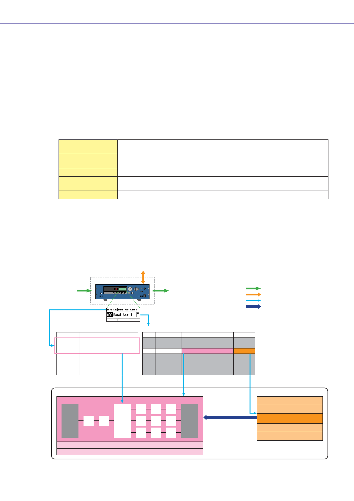
■ One DME unit/Zone
External Device (MIDI, GPI, DAW, AMX/Crestron)
Microphone
Mixer
External Head Amp
etc...
Input
Zone
Output
Power Amp
Processor
etc...
Notes
Audio signal
Control signal
Data explanation
Setting preset data
User Defined Button Scene Manager
LCD Display
Dome Low
Dome Mid
Dome Hi
....
Specifies the parameter to be changed.
Configuration
Output Processor for Dome
Local parameter link settings
External device settings
Assigned Parameter
Crossover: Output Low: Level
Crossover: Output Mid: Level
Crossover: Output Hight: Level
(No Assign)
(No Assign)
(No Assign)
MY8-AE
(Input)
EQ
Delay
Cross-
Over
No.
Scene Name
001
All On
002
Opening
003
Band Set 1
004
Band Set 2
005
Band Set 3
006
...
....
Delay EQ Dyn
Confuguration
Output Processor for Dome
Output Processor for Dome
Output Processor for Dome
Output Processor for Dome
Output Processor for Dome
...
Specifies the configuration
and preset data combination.
MY8-AE
(Output)
Set the value
Preset
All On
BGM & MC
Band 1
Band 2
Band 3
Preset data for output processor
All On Component value
BGM & MC
Band 1
Band 2
Band 3
DME Designer Owner’s Manual
3
Page 4
Getting Started
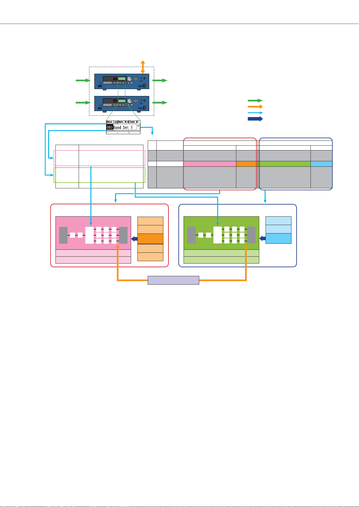
■ Two DME units/Zone
When one DME unit doesn’t provide sufficient processing power, up to 16 DME units can be used
External Device (MIDI, GPI, DAW, AMX/Crestron)
Input Output
Microphone
Mixer
External Head Amp
etc...
For DME#1
For DME#2
Input Output
User Defined Button
LCD Display
Dome Low
Dome Mid
Dome Hi
Hall Low
Hall Mid
Hall Hi
....
Selects the parameter to be
edited from two DME units.
DME#1
Configuration
Output Processor
for Dome
Local parameter link settings
External device settings
Assigned Parameter
#1: Crossover: Output Low: Level
#1: Crossover: Output Mid: Level
#1: Crossover: Output Hight: Level
#2: Crossover: Output Low: Level
#2: Crossover: Output Mid: Level
#2: Crossover: Output Hight: Level
DME#1
DME#2
Zone
Power Amp
Processor
etc...
Notes
Audio signal
Control signal
Data explanation
Setting preset data
Scene Manager
No.
Scene Name
001
All On
002
Opening
003
Band Set 1
004
Band Set 2
005
Band Set 3
006
...
....
Preset data Preset data
All On
BGM & MC
Band 1
Band 2
Band 3
Configuration
Output Processor for Dome
Output Processor for Dome
Output Processor for Dome
Output Processor for Dome
Output Processor for Dome
...
DME#2
Configuration
Output Processor
for Hall
Local parameter link settings
External device settings
For DME#1 For DME#2
Preset
All On
BGM & MC
Band 1
Band 2
Band 3
Configuration
Output Processor for Hall
Output Processor for Hall
Output Processor for Hall
Output Processor for Hall
Output Processor for Hall
...
Specifies the configuration and preset
data combination in each DME
All On
BGM & MC
Band
Preset
All On
BGM & MC
Band
Band
Band
Specifies the parameter to be linked between DME units.
Grobal Parameter Link
DME Designer Owner’s Manual
4
Page 5
Getting Started
Common data for DME units in the same zone
Scene Manager A “scene” is information that is used to change the audio processing content.
MIDI Program Change
settings
User Defined Button setting This information is necessary to control component parameters from the unit’s
Global parameter link settings This information is necessary to allow operation of similar parameters to be
Separate data for individual DME units
Configuration This information defines the configuration of audio processing, audio input/
Local parameter link
settings
External device settings This information is necessary to allow control of component parameters from
Preset data These are the parameter values for the components included in a configuration.
A combination of a configuration and preset data is specified for each scene.
A Scene Manager is function used to memorize and manage scenes. Up to 999
scenes can be memorized, and each scene is managed by number.
This setting is necessary to switch scenes using MIDI messages.
panel. Up to 24 parameters can be memorized.
linked between multiple DME units.
output, and external device components and the connections between
components required to achieve the desired audio processing.
This information is necessary to allow linked operation between similar
parameters within a single DME unit.
external devices.
Independent settings are required for each external device.
The following external devices can be used:
• MIDI controller( MIDI Control Change, Paramter Change)
• GPI controller
• DAW controller
• AMX, Crestron, and similar remote controllers.
Audio processing details can be changed by changing the preset data.
The following component types include preset data:
• GEQ, Matrix Mixer, and other audio processing components.
• Internal AD/DA (DME24N), Cascade (DME64N), and MY Card I/O
components.
• External device components for external head amps (AD8HR, AD824).
System Requirement
Operating System Windows
CPU 1 GHz or better Intel
Memory At least 256 MB
Hard Disk Capacity At least 300 MB
Display 1,280 x 1,024 pixels or better/High Color 16 bit or better
Other Mouse, CD-ROM drive, 100Base-TX/10Base-T Ethernet or USB connection
environment.
®
XP Professional/XP Home Edition/2000 Professional
®
Pentium®/Celeron® family processor
DME Designer Owner’s Manual
5
Page 6

Getting Started
Main Changes from V1.0 to V1.1
■ Main Panel Window
• Instead of the former Parameter Link function, there are now two functions: a Global Link function
that links parameters within all DMEs in a zone and a Local Link function that links parameters
within a single DME unit. (→ page 73)
• The Synchronization function can now not only send data from DME Designer to the DME unit,
but can also synchronize by reading data from the DME unit. (→ page 75)
• Scene Increment/Decrement and Time Adjustment can now be assigned in the GPI input
function. (→ page 80)
• DME unit events can now be recorded by the Event Logger function and displayed in the Event
Logger window. (→ page 111)
• The time for executing an event can now be set by using the Event Scheduler function.
(→ page 116)
• Parameters in the current configuration can now be listed on the display and printed out by using
the Parameter List function. (→ page 124)
• The Wav File Manager can manage Wave files played by the Wav File Player. (→ page 128)
• Settings can be made by the DAW Control function that are used for controlling DMEs from a
DAW controller. (→ page 132)
• DME unit data can now be saved as a backup file by using the Backup function. (→ page 135)
■ Designer Window
• The port name display can now be switched between long name display and short name display.
(→ page 148)
• DME64N cascade connections can now be set. (→ page 165)
• Priority items can now be set when compiling configurations by using the [Compile Priority]
function in the “Preferences” dialog box. (→ page 209)
• Delay time can now be displayed for each component by using the Show Signal Delay function.
(→ page 246)
• Monitoring points can now be edited by using the “Monitoring Point List” dialog box. (→
• The status of connections in a configuration can now be analyzed in advance by using the
Analyze function, without connecting the DME unit. (→ page 249)
•You can now set the action that occurs when you double-click a user module object. You can also
turn user module security ON or OFF, and set a password. (→ page 254)
• Libraries with component parameters saved in them can now be recalled from the context menu
for a component object. (→ page 277)
•A new rule for wiring prohibits connections to terminals that would short the terminator.
page 247
■ Component Editor/Component
•A status bar has been added to the component editor. It displays the component name,
component ID, and parameter IDs for parameters that are being edited. (→ page 265)
•A Snap function has been added that records parameters in the editor temporarily. Parameter
sets can then be switched by using the Snap buttons. (→ page 273)
• The meter's peak hold function can now be turned ON or OFF. (→ page 291)
•A Wav File Player component has been added for playing Wave files. (→ page 359)
• An effect component called SPX has been added that supports many different effect
applications, such as reverb, delay, and modulation effects, along with complex combinations of
multiple effects. (→ page 397)
•A Slot Out component editor has been added. (→ page 409)
• An Undo/Redo function is now available when using the design mode. It can undo the most
recent operation (control movement/resize/deletion).
)
DME Designer Owner’s Manual
6
Page 7

Changes from V1.1 to V1.2
■ Main Panel Window
• The synchronization algorithm has been refined for faster synchronization.
• Synchronization now can be executed from DME to DME Designer without any break in the
sound.
• In the following cases, synchronization can be executed from DME Designer to DME without any
break in the sound:
The second or later synchronization after starting DME Designer* and when differences in data
between the DME and DME Designer are limited to parameters within components, AD824/
AD8HR/DME24N AD/DA setting data, or MY card setting parameters.
* If the file was saved when DME Designer was closed, there will be no break in sound even in the first
synchronization after saving.
• Compile speed has been increased.
Up to three times faster when AutoDelayCompensation is turned On.
Up to two times faster when AutoDelayCompensation is turned Off.
• Synchronization is possible when no MY card or a different MY card is installed in the DME unit
(a confirmation dialog will appear).
• An option to automatically close the dialog after synchronization has been added. (→ page 37)
•A progress bar has been added to the Synchronization dialog. (→ page 36)
•A message appears to warn when synchronization will cause muting.
• The following operations can be performed while on line:
- Scene storage.
- Scene name changes.
- Fade ON/OFF and Fade Mode changes.
- Fade time changes.
- Parameter link setting changes.
• When a scene store is executed, that scene becomes the current scene.
•Wave files can be saved as DME data files, and are included in import/export operations.
(→ page 32)
•Wave files can be saved in the Wav file library.
• Event Log events can be output via GPI. (→ page 115)
• The on-line indicator appears as a button which can be used to switch between on-line and
off-line. (→ page 43)
• Scene edits cause the EDIT indicator to appear. (→ page 42)
• An auto file save function (Auto Save, post synchronization) has been added. (→ page 53)
• Different zones can be specified for use by different users. (→ page 56)
• Scene parameters related to User Defined Button, Program Change, GPI In and GPI Out can be
set via the Scene Manager. (→ page 63)
• [Select All] and [Clear All] buttons have been added to the Scene Manager Recall Safe dialog.
(→ page 67)
• User Control can be created for individual users as well as security levels. (→ page 70)
•A Remote Control Setup List has been added. (→ page 123)
This list can be used to make detailed settings for a new software protocol that allow the DME to
be controlled from AMX, Crestron, and similar devices.
Refer to the “DME-N Remote Control Protocol Specifications” document for details about the
communication protocol. Information about the “DME-N Remote Control Protocol Specifications”
document can be found at the Yamaha pro Audio website (URL below).
http://www.yamahaproaudio.com/
• It is possible to specify whether listed events will be executed by the Event Scheduler.
(→ page 116)
Getting Started
DME Designer Owner’s Manual
7
Page 8

Getting Started
• The order of same-time events can be changed in the Event Scheduler. (→ page 116)
• Exceptions can be specified for Event Scheduler execution day/time. (→ page 122)
• Event Scheduler execution times can be specified in 1-second increments. (→ page 121)
• Head amp gain and MY-Card can be set via GPI, MIDI, User defined Button, DAW Control.
• Parameter values, scene recall, GPI output, Wave file playback, and head amp gain can be set
via the User Defined Buttons. (→ page 98)
• The Component Lock function dialog is separate from the Parameter List dialog. (→ page 127)
• Shortcuts can be freely set as required. (→ page 134)
• Files can be saved in the DME unit. (→ page 52)
•A [Close All Editor Windows] button has been added to the Window menu. (→ page 51)
• External head amp parameters will be recognized by the DME unit when either the DME or the
external head amp (AD824, AD8HR) are turned on. Execute a scene recall to send DME settings
an external head amp.
• This manual is now separate from the DME Designer installer, and can not be accessed from the
DME Designer menus.
■ Designer Window
• The following operations can be carried out via the shortcut keys.
- Navigator
- Activate Navigator
- Activate Toolkit
- Activate Design Window
- Select Left Port and Start Wiring
- Select Right Port and Start Wiring
- Wire Auto Single to Right
- Wire Auto Multi to Right
- Wire Auto Single to Left
- Wire Auto Multi to Left
- Delete Wire
• It is now possible to simultaneously edit multiple objects of the same type.
Example: Change the thickness or color of multiple wires at once.
• Files related to user modules (user module files, library files, user module editor files) can be
combined and exported/imported as a single file.
• Port colors can be independently specified for each port type. (→ page 156)
• Default wire thicknesses and types can be independently specified for each port type.
• An automatic hot-spot connection function has been added. (→ page 225)
• Port display has been added to External Device, Picture, DME, and ICP1 objects.
• When drawing wires the keyboard cursor keys can be used to move the mouse cursor, and the
<Enter> key can be used to create nodes.
• When drawing wires <Shift> key plus <→> key and <Shift> key plus <←> key combinations can
be used to automatically connect horizontally-aligned hot spots.
• DME object ports can be freely specified.
• Compilation of configurations with loop connections is possible when Auto Delay Compensation
is On.
• The name has been changed from “Foot Monitor” external device to “Floor Monitor.”
• Addition External Device types have been provided.
• External Devices can be double-clicked to open a file saved by other applications. (→
• Picture objects can be double-clicked to open a specified editor. (→ page 187)
•Text objects can be double-clicked to open a specified editor. (→ page 190)
page 172
)
DME Designer Owner’s Manual
8
Page 9
Getting Started
• User module port labels can be edited. (→ page 183)
• Graphics can be placed to represent user modules. (→ page 183)
• The Legend field automatically resizes to accommodate project names and titles of different
lengths.
•A Generic “MY-Others” setting has been provided to accommodate third-party MY cards.
■ Component Editor Window
• Undo and Redo are now shortcut compatible.
•A scroll bar appears when the size of the component editor window is reduced.
• The size and position of the component editor window are memorized.
• An option to allow mouse-over zooming of the edit box has been added. (→ page 266)
•A [Back] button that allows switching between related parent and child windows has been
added. (→ page 265)
•A [Close All Editor Windows] button has been added to the contextual menu.
• Source Selector, Speaker Processor, Limiter, Slot In, Cascade In, and Cascade Out components
have been added.
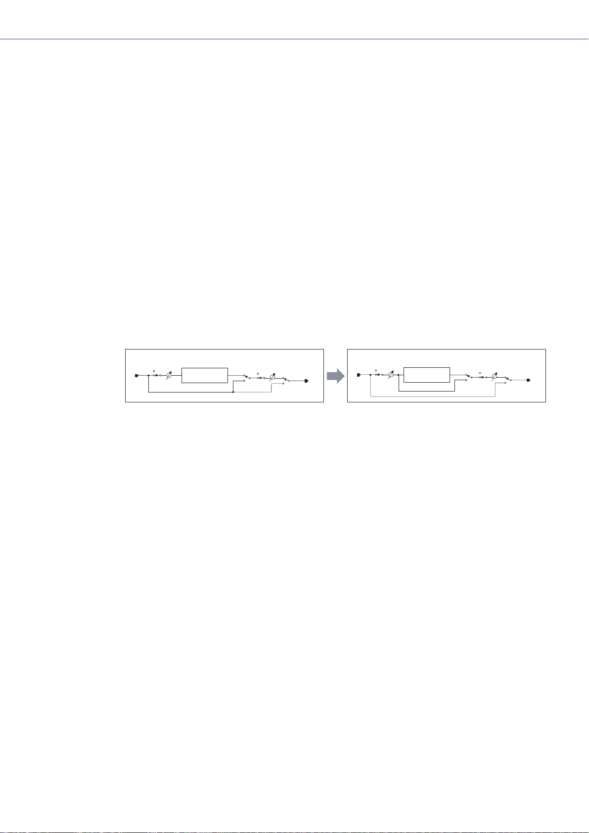
• The Delay algorithm has been revised. (→ page 332)
- LEVEL and MUTE are effective when Delay is Off for each channel.
- The name of the overall Delay [On] parameter has been changed to [All Bypass].
Input
Input
Input
Mute
IN
Level
Delay
Mute Level
On
Delay On
OUT
IN
Mute
Input
Level
Delay
On Mute Level
Delay All Bypass
OUT
• The bus send level range for Delay, Matrix, and Matrix Mixer components has been changed to
-∞ through 0.0 dB.
• Snap copy is possible. (→ page 274)
• Snap can be retained until the application is quit or another file is opened.
• Security status is displayed in the user module editor status bar.
• Multiple controllers can be selected by clicking while holding the <Ctrl> key when the editor is in
the design mode. (→ page 286)
• [Picture], [Text], [Box], [Ellipse], and [Frame] have been added to the tool palette of the user
module editor and user control editor design mode. (→ page 279)
• Controller properties can be accessed by double-clicking controllers in the user module editor or
user control editor design mode. (→ page 303)
• Picture and Text objects can be clicked to open a specified editor in the user module editor or
user control editor.
• The User Module Editor and User Control Editor offer a greater range of customization options for
color, size. etc., of the placed controls.
■ MIDI Setup
•A MIDI Setup minimize function has been added.
■ V1.2 Precautions
• When using project files (*.daf) created by version 1.1.5 or earlier, synchronize from the DME
Designer to the DME unit for the first synchronization.
•Project files (*.daf) created using version 1.2 will not open properly on version 1.1.
DME Designer Owner’s Manual
9
Page 10

Contents
Chapter 1 Before Using 11
Installing DME Designer.....................................................11
Starting DME Designer.......................................................11
Closing DME Designer.......................................................13
Chapter 2 DME Designer Overview 14
Names and Functions of the Windows...............................14
Users and Security.............................................................19
Project Files........................................................................22
DME Data File....................................................................30
Configuration Creation Procedure......................................34
Online.................................................................................35
Chapter 3 Main Panel Window 39
Main Panel Window............................................................39
Main Panel Window Menu..................................................44
DME File Storage...............................................................52
Preferences........................................................................53
Security (Creating Users and Making User Settings).........55
Scene Manager..................................................................63
User Control .......................................................................70
Parameter Link...................................................................73
Synchronization
(DME Designer and DME Unit Synchronization)................75
GPI .....................................................................................79
MIDI....................................................................................90
User Defined Button (User Defined Parameters)...............98
Word Clock.......................................................................102
Monitor .............................................................................104
Clock ................................................................................105
Language Settings ...........................................................106
DME Firmware Update.....................................................107
Event Logger....................................................................111
Event Scheduler...............................................................116
Remote Control Setup List ...............................................123
Parameter List..................................................................124
Component Lock ..............................................................127
Wav File Manager ............................................................128
DAW Control.....................................................................132
Shortcut Keys...................................................................134
Backup .............................................................................135
Chapter 4 Designer 136
Drawing and Editing Wires ...............................................219
Adding, Deleting, and Renaming a Zone..........................231
Adding, Deleting, and Renaming a Configuration.............233
Area Window ....................................................................235
Zone Window....................................................................237
Configuration Window.......................................................242
User Module .....................................................................250
Chapter 5 Components 259
Types of Components.......................................................259
Component Editor Window...............................................264
Snap .................................................................................273
Library...............................................................................275
User Control/User Module Editor......................................279
Creating Parameter Links.................................................314
Chapter 6 Component Guide 316
Crossover .........................................................................316
Crossover Processor........................................................320
Delay.................................................................................332
Dynamics..........................................................................334
Equalizer (EQ)..................................................................344
Fader ................................................................................348
Filters................................................................................349
Meter.................................................................................357
Miscellaneous...................................................................358
Mixer.................................................................................360
Pan ...................................................................................378
Router...............................................................................386
Source Selector................................................................388
Speaker Processor...........................................................390
SPX...................................................................................397
Slot....................................................................................408
Cascade............................................................................410
Internal Head Amp............................................................412
MY-Card ...........................................................................413
Remote Controlled Head Amp..........................................417
Component Glossary........................................................419
Troubleshooting 423
Index 424
Editing Configurations ......................................................136
Designer Window .............................................................137
Designer Window Menu ...................................................144
Toolkit Window.................................................................152
Objects .............................................................................156
Design Window Shared Settings and Operations ............207
DME Designer Owner’s Manual
10
Page 11
Chapter 1 Before Using
Installing DME Designer
To use DME Designer, you must first install the software on the computer. Before you can connect the
DME Designer software to the DME unit, send and receive configurations, or perform control, you must
first install the USB MIDI Driver or the DME-N Network Driver, according to how you will be connecting,
and then make the appropriate settings.
For instructions about how to install DME Designer and about the installation and setup method for the
MIDI driver and DME-N Network Driver, see the “DME Designer Installation Guide.”
Starting DME Designer
The DME Designer software is started from the [Start] menu. DME Designer is used with one user
logged on. The user logs on when the software is started.
■ DME Designer Start Up and Logon (When Auto-Logon Is Not Set)
1 Click [Start] ➞ [All Programs] ➞ [YAMAHA OPT Tools] ➞ [DME Designer] ➞ [DME
Designer].
NOTE
In Windows2000, click [Start] → [Programs] → [YAMAHA OPT Tools] → [DME Designer] → [DME Designer].
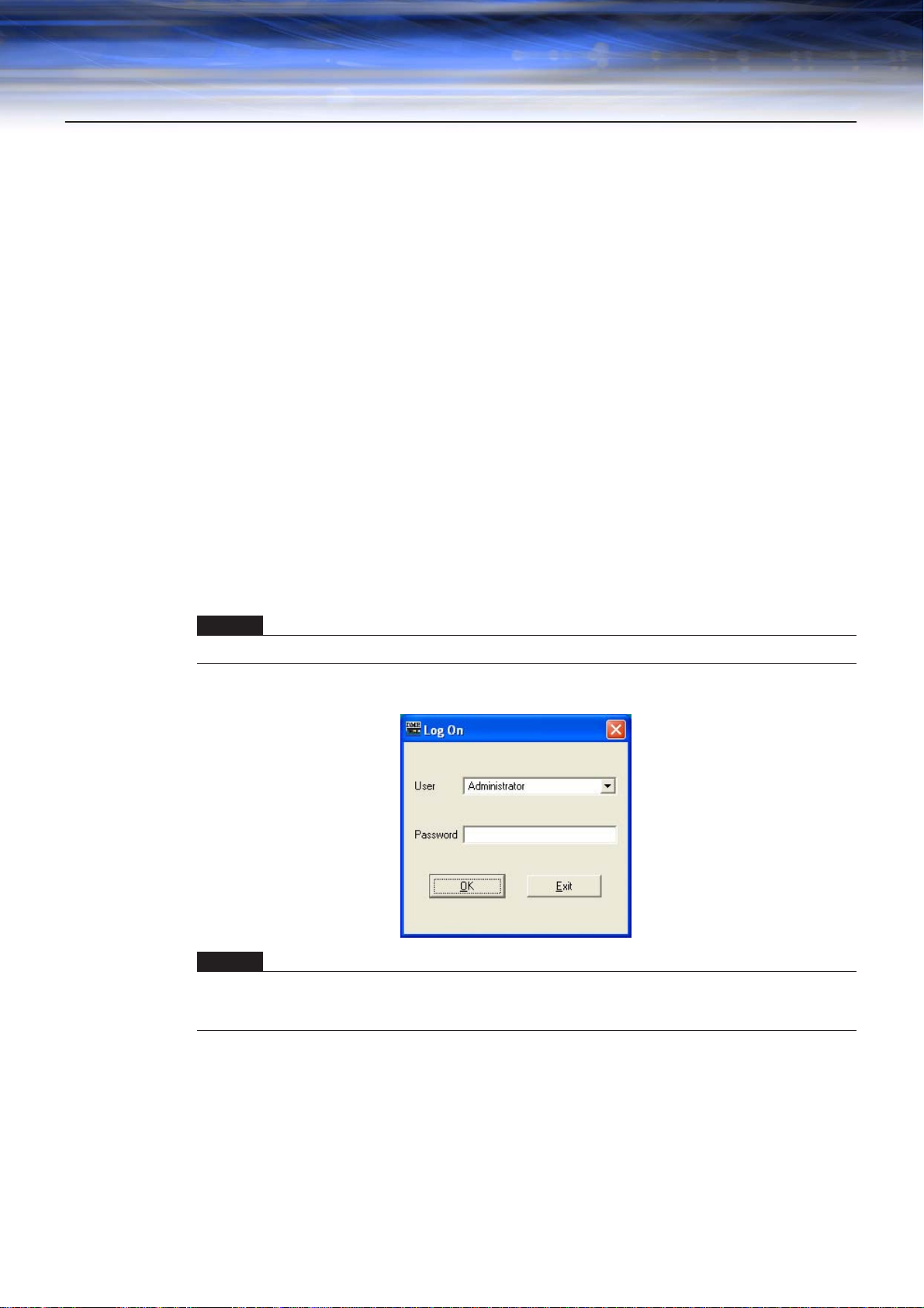
The “Log On” dialog box will be displayed.
NOTE
Automatic log-on is the default setting. If the automatic logon feature is enabled, the “Log On” dialog box will not be
displayed when the application is started. Instead, the auto-logon user will be logged on automatically. See page 21
for information about auto-logon.
2 Click the [▼] at the right of the [User] box, and select the user.
If no user has been created, only [Administrator] will appear in the list. When starting DME
Designer for the first time after installing, select [Administrator].
DME Designer Owner’s Manual
11
Page 12
Chapter 1 Before Using
3 Enter the password into the [Password] box.
4 Click the [OK] button.
Enter the password set for the user.
If no password has been set, leave the password box blank when you log on.
DME Designer starts up.
■ When Automatic Logon Has Been Set (page 21)
If automatic logon has been set, the “Log On” dialog box will not be displayed. The user set for
automatic logon will be logged on.
With automatic log on, even if a password is set for a user, it will not be requested during log on.
This is useful when logging on a specific user.
■ Starting by Opening a Project File
DME Designer starts when a project file with a saved configuration is opened. When the project file
is opened, DME Designer is started with the window configuration that was in place when the file
was last saved.
DME Designer Owner’s Manual
12
Page 13
Closing DME Designer
To close DME Designer, click [Exit] on the [File] menu of the Main Panel window. It can also be closed
by clicking the [Close] button on the Main Panel window.
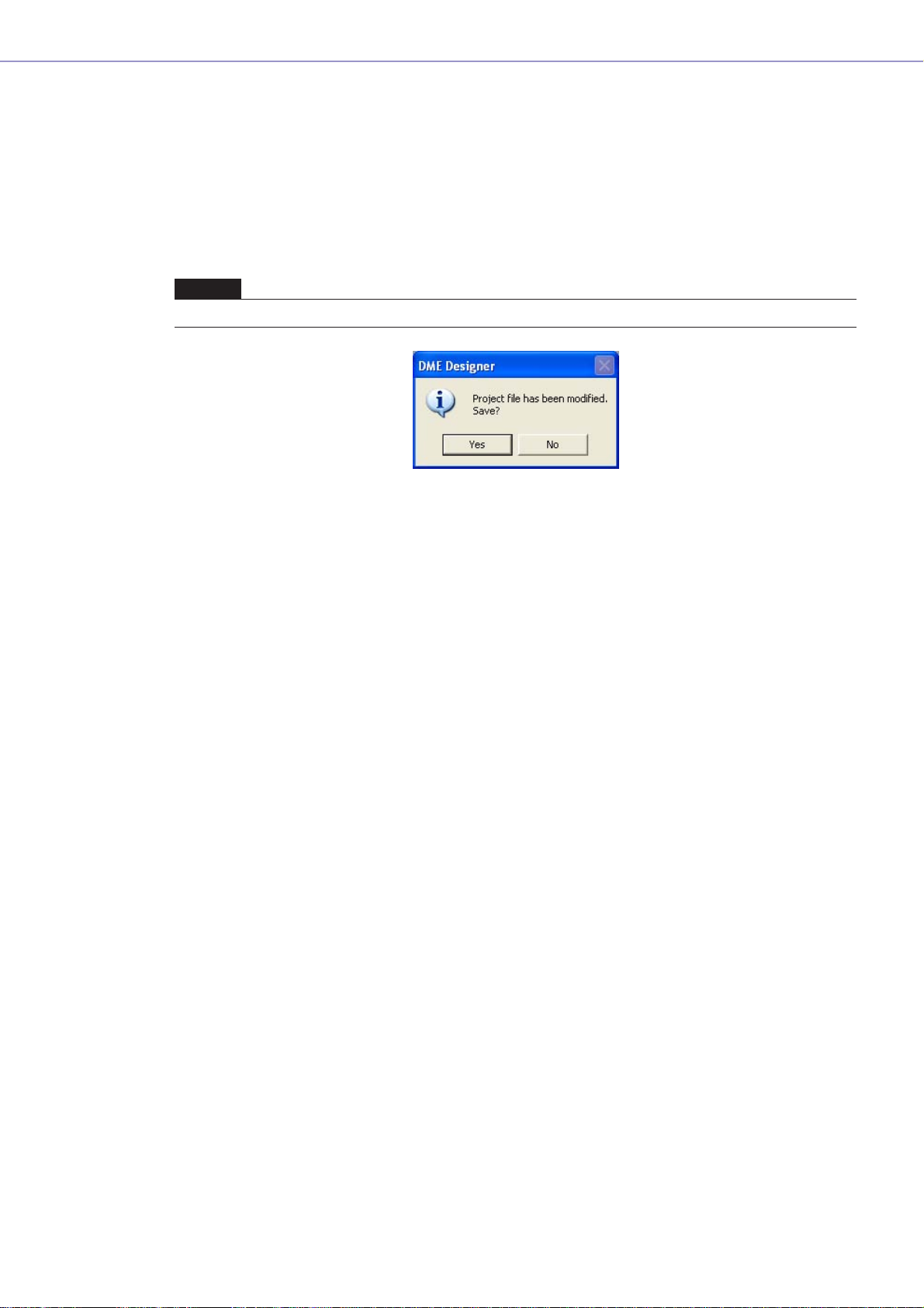
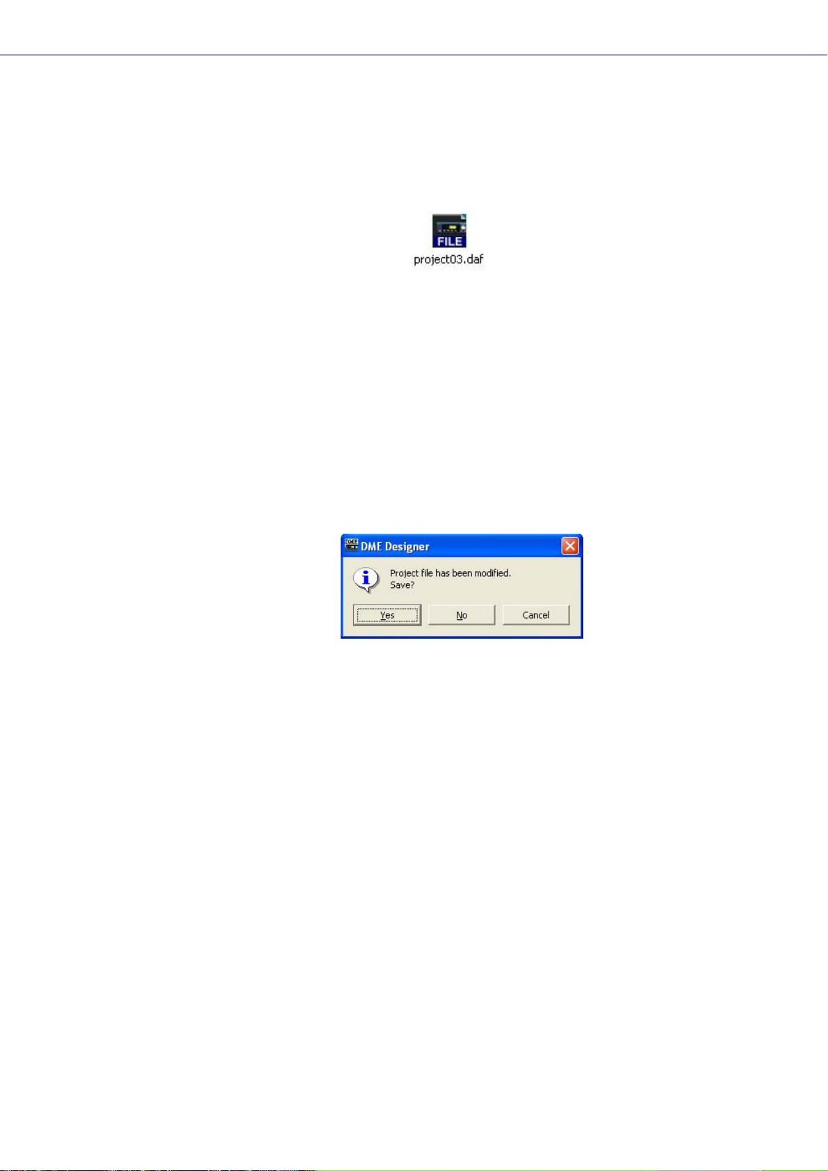
1 Click [Exit] on the Main Panel window [File] menu.
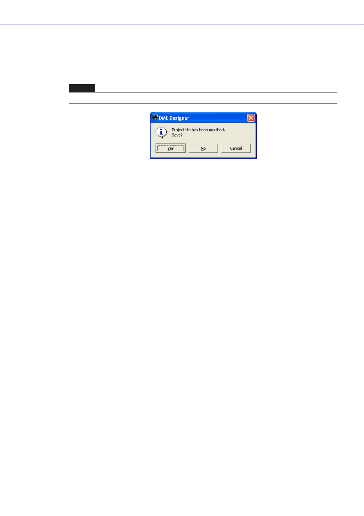
When you try to close DME Designer, “Project File has been modified. Save?” will be displayed in a
dialog box.
NOTE
Sometimes the “Project File has been modified. Save?” dialog box will not be displayed.
Chapter 1 Before Using
2 To save the file, click [Yes]. To close without saving, click [No].
If you click [Yes], the file currently saved with the same name will be overwritten. If the file has not
been saved, the File Save dialog box will always be displayed.
DME Designer Owner’s Manual
13
Page 14
Chapter 2 DME Designer Overview
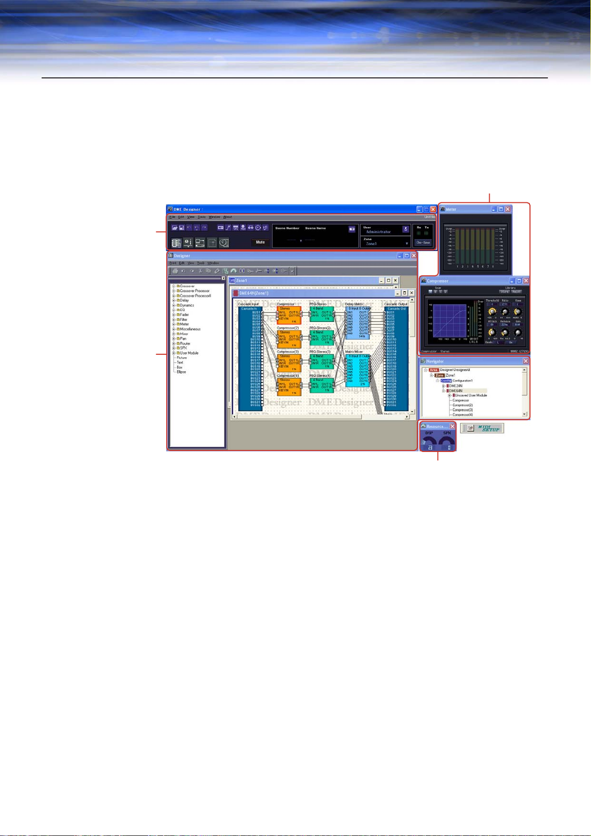
Names and Functions of the Windows
The DME Designer software has several windows, including the Main Panel window, Designer window,
Component Editor window, Resource Meter window, and others.
Main Panel Window
Designer Window
Component Editor Window
Resource Meter Window
Main Panel Window
Menus and buttons are available in the Main Panel window. The current DME Designer environment,
including the active scene and zone, the currently logged on user name, and the connection status to
the DME unit are displayed on the right side of the Main Panel window.
DME Designer Owner’s Manual
14
Page 15
Chapter 2 DME Designer Overview
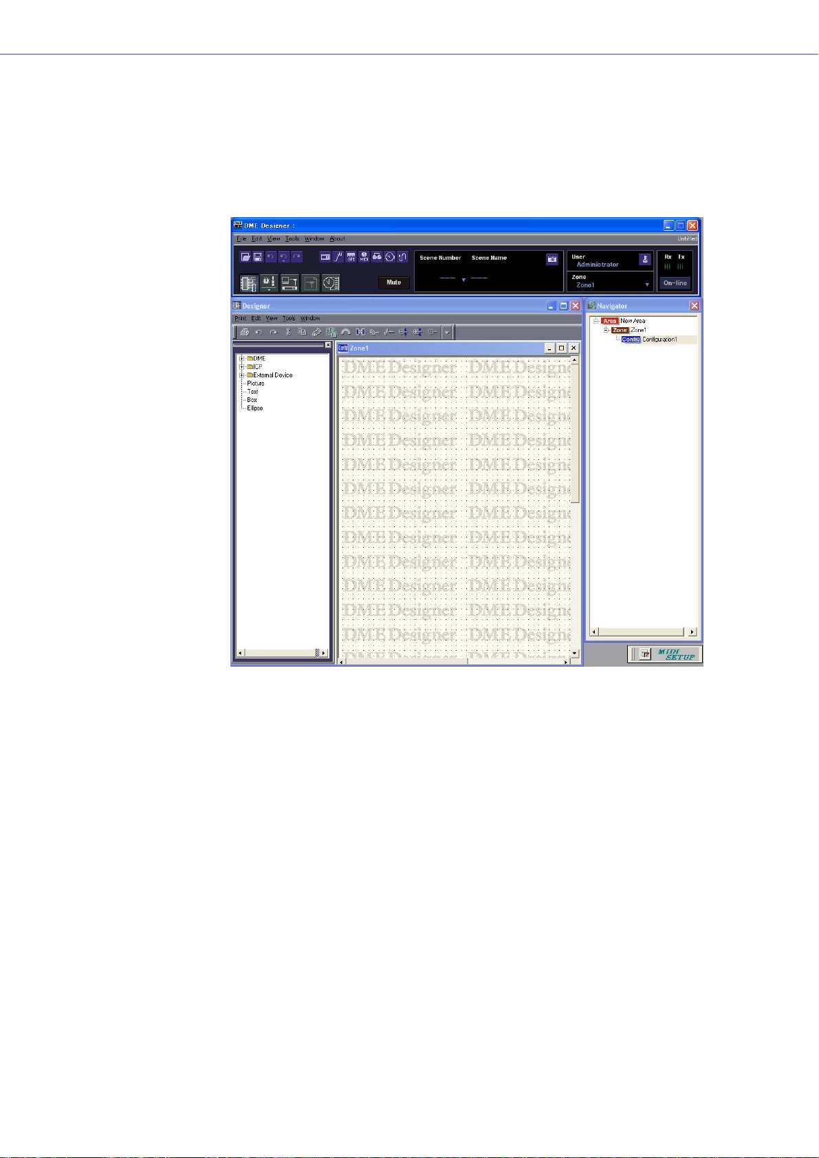
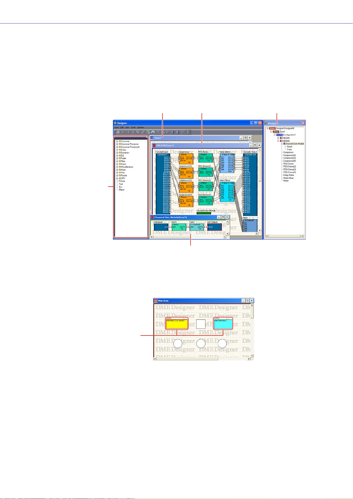
Designer Window
The Designer window displays several different windows. First among them is the Area window, where
you can manage the entire system. The Area window includes one or more Zone windows, which in
turn include one or more DME units that are used to build a zones within the area. Next is the
Configuration window, where you create the internal configuration of each DME unit. Within the
Configuration window are the User Module windows, where you can assemble often-used
components into presets; the Toolkit window, which displays objects used in the other windows as the
basic building blocks for sound designs; and the Navigator window, which lets you grasp the overall
status of the system at a glance.
Toolkit Window
Zone Window
Configuration Window
Navigator Window
User Module Window
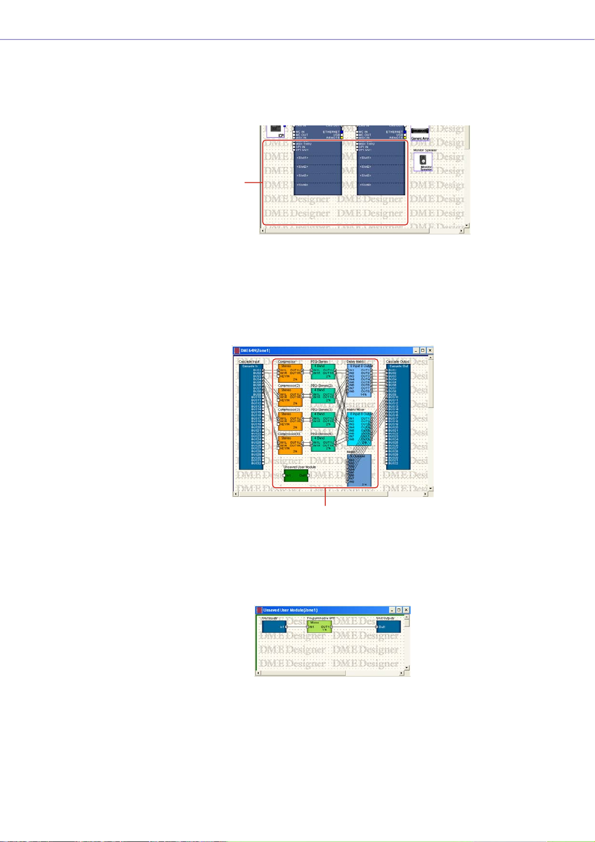
■ Area Window
The Area window is used for designing areas, which manage the entire system. While at least one
zone is included within an area, multiple zones can be arranged there.
Zones
DME Designer Owner’s Manual
15
Page 16
Chapter 2 DME Designer Overview
■ Zone Window
The Zone window is used to design zones within the area. A zone is a more concrete blueprint that
includes at least one DME. It shows the DME’s connections with other devices and the wiring
between them. You can create multiple zones.
The DME units and connected devices are arranged in each Zone window, creating configurations.
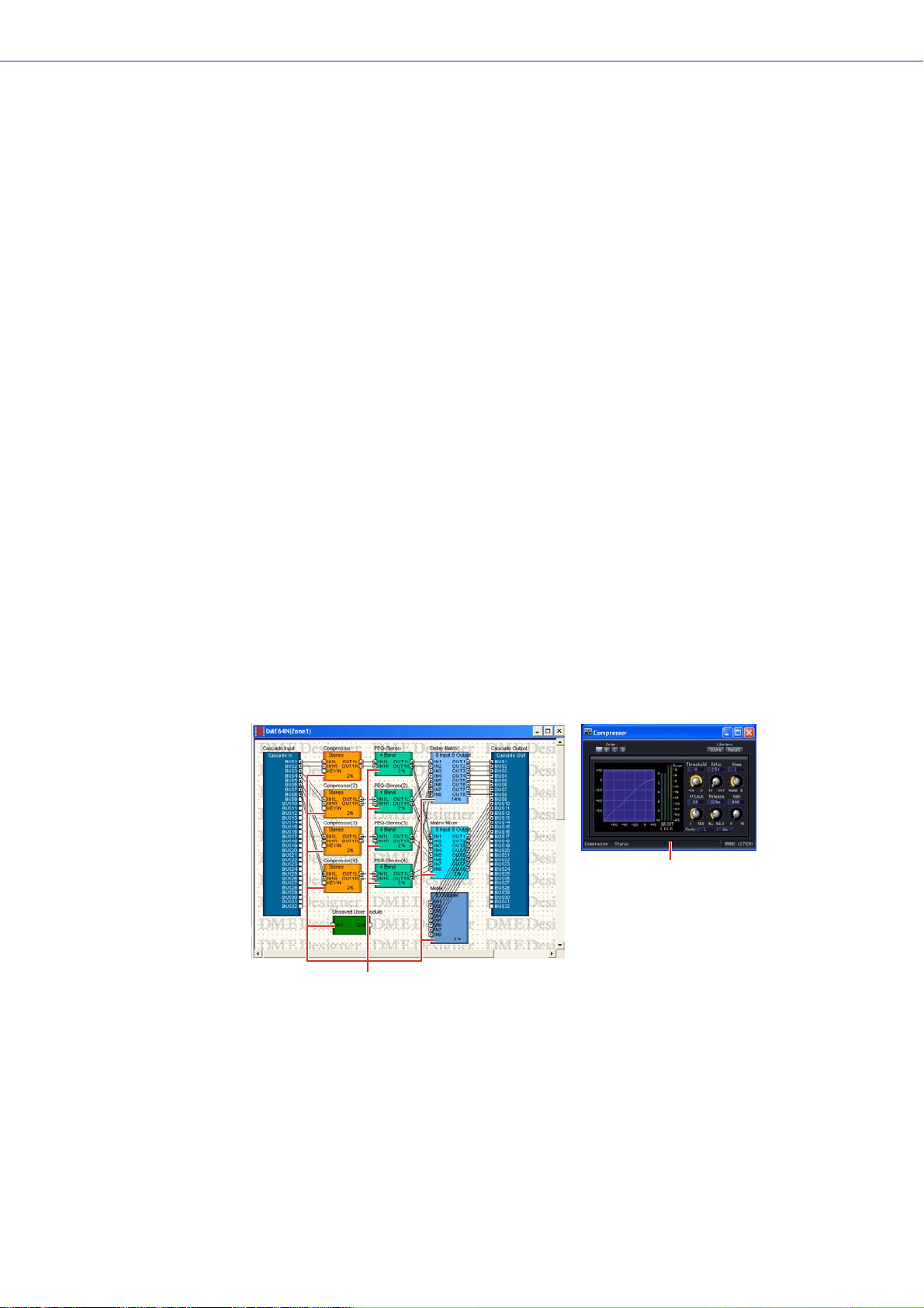
■ Configuration Window
The Configuration window is used to design the internal configuration of each DME unit contained
in the Zone window. By arranging and connecting components (audio processors like mixers,
compressors, effects, and crossovers, along with parts like faders and meters) in the Configuration
window, you can create things like complex processors or matrix mixers, that determine the actual
internal structure that operates each DME unit.
Configurations
Components
■ User Module Window
The User Module window is used for designing user modules that can be arranged in the
Configuration window. You can create original modules by combining multiple examples of oftenused components. When you save these modules as presets, you can recall them easily whenever
you want.
DME Designer Owner’s Manual
16
Page 17
Chapter 2 DME Designer Overview
■ Toolkit Window
The Toolkit window displays the objects that you can use in each window that can be displayed in
the Designer window. Those windows are the Area, Zone, Configuration, and User Module
windows. The Toolkit displays different objects, according to the currently active window. To place
an object in a window, double-click it in the Toolkit window where it is displayed or drag it to the
currently active window.
■ Navigator Window
The Navigator window displays the area, zones, configurations, and components in a hierarchal
fashion that lets you check their status as a whole. When editing offline, you can click an area
name, zone name, or configuration name to make that window active. Clicking a component name
will open the component editor window for that component.
■ Objects and Components
“Object” is the name for the parts that are arranged in the various design windows, such as the
Area, Zone, Configuration, and User Module windows. Objects are always laid out in the Toolkit
window. Only the appropriate objects for each window are displayed. The blocks displayed at the
higher level of the Toolkit window in particular are called “components.” This refers to each type of
processor that operates the DME. “Object” normally refers to Picture, Text, Ellipse and other items
that are used after connecting them by wire to the various components.
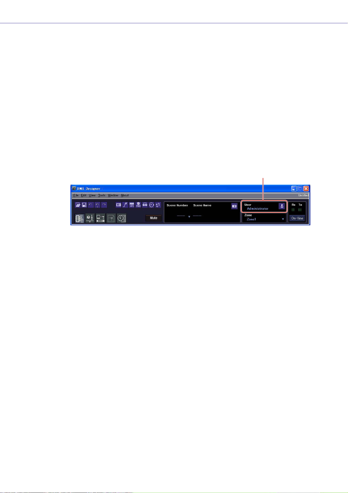
Component Editor
The blocks that are arranged in the configuration window are called “components.” Audio processors
like mixers, compressors, effects, and crossovers, along with parts like faders and meters, are used
for this purpose in the Configuration window.
When you double-click on a component block arranged in the Configuration window, the Component
Editor window will open. There you can edit the parameters for that component. The types of
parameters displayed will differ, depending on the component.
Component Editor
(Stereo Compressor)
Component
DME Designer Owner’s Manual
17
Page 18

Chapter 2 DME Designer Overview
Resource Meter
This window provides an indication of the usage of the components in the configuration window. The
usage percentage increases as the number of components increases, and is shown in graph form in
this window.
This window is shown at the same time as the designer window, and provides a guide when creating
configurations.
The usage percentage also depends on the sampling frequency at which the DME unit is set to
operate. Make sure that the usage percentage is kept below 100%.
Window Operations
Operations in all windows are the same as for normal Windows applications. The windows are
controlled with the [Minimize], [Maximize/Restore], and [Close] buttons at the upper right of the title
bar. DME Designer is closed by clicking the [Close] button on the Main Panel window.
DME Designer Owner’s Manual
18
Page 19
Users and Security
You can create multiple users in DME Designer and set the functions that are available to each user.
Although users who will design and put together installations must be able to use all the functions of
DME Designer, users who will only operate the system can be restricted to functions that will not allow
them to accidentally change the settings.
DME Designer is used with one user at a time logged on. To change the user, click the [File] menu →
[Log Off] command on the Main Panel window.
About Users
To use DME Designer, you must logon when you start the software. Except for the first time the
software is started or when separate settings are made for the first time, you can logon by specifying
the name and password for a user that has been set as the administrator. The administrator can build
the system as a whole, or apply function limitations that let other people edit. Administrators or other
people that can use DME Designer are called “users.” The user name for the currently logged on user
appears below [User] on the Main Panel window.
Chapter 2 DME Designer Overview
Currently Logged On User Name
The default user, named [Administrator], is set to use all of the functions. Immediately after DME
Designer is installed, [Administrator] is the only user, and there is no password set.
Multiple users can be created. When the system administrator creates multiple users, restrictions can
be applied separately for each one of them. A user with restrictions applied can edit using only the
functions the administrator enables for him.
The place to create, setup, and delete users is the “Security” dialog box. See “Security (Creating
Users and Making User Settings)” on page 55.
DME Designer Owner’s Manual
19
Page 20
Chapter 2 DME Designer Overview
1
2
3
5
Logging On
The “Log On” dialog box is displayed whenever the application is started or a user is logged off.
Whenever one user is already logged on, another user cannot be logged on. To log on as another
user, first log off the currently logged on user.
NOTE
If the automatic logon feature is enabled, the “Log On” dialog box will not be displayed when the application is started.
Instead, the auto-logon user will be logged on automatically.
■ The “Log On” dialog box
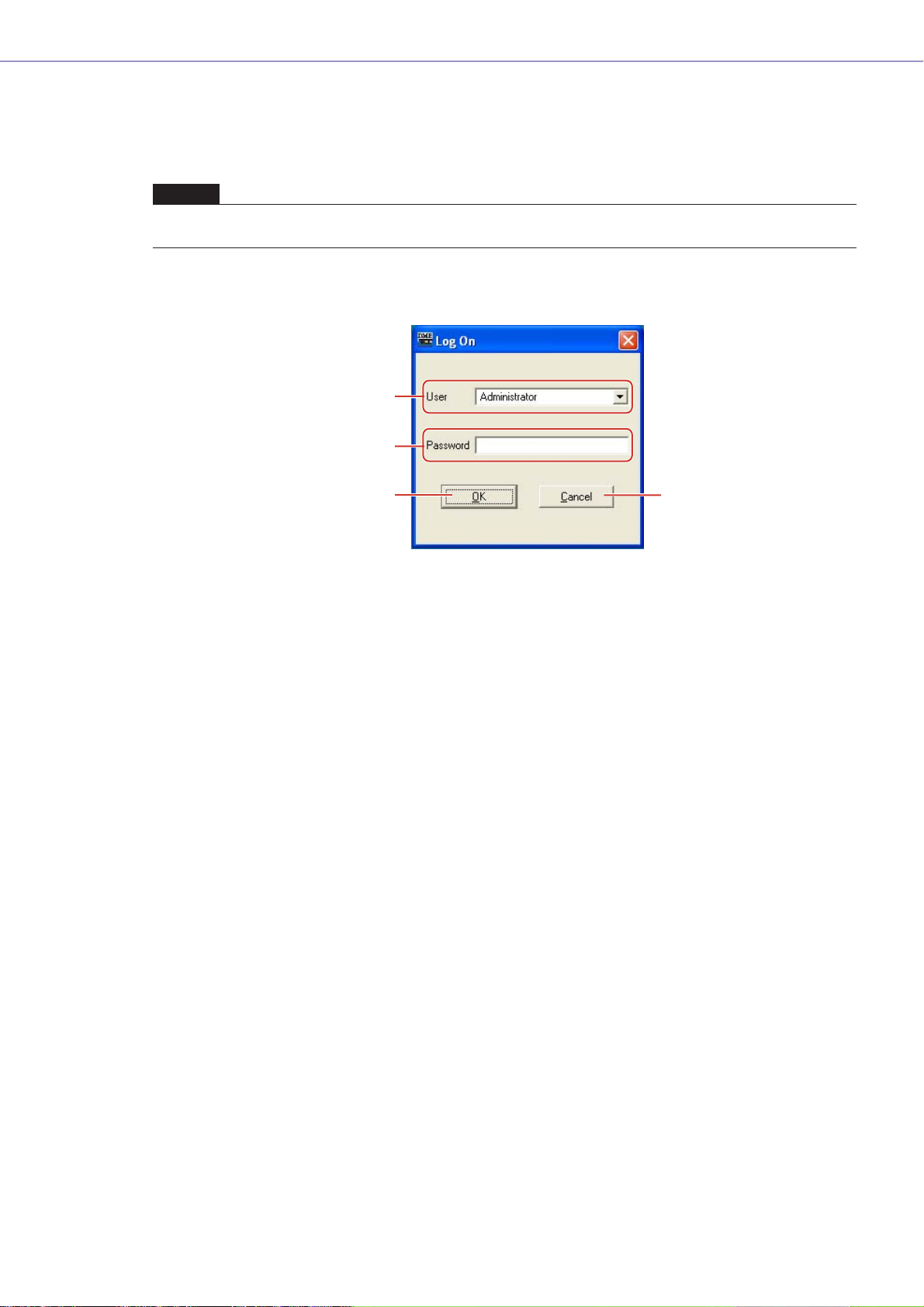
1 [User]
From the list, select the user you want to log on as.
2 [Password] Box
Enter the password.
3 [OK] Button
Log on as the selected user.
4 [Exit] Button
When the application is started, and the “Log On” dialog box is displayed, there is an [Exit]
button. This closes the application without logging on a user.
5 [Cancel] Button
When the “Log On” dialog box is displayed after a user is logged off, there is a [Cancel] button
instead of an [Exit] button. This cancels the logoff. The original user will continue to be logged
on.
■ Logon Procedure
1 Click [▼] at the right of the [User].
A drop-down list of user names will be displayed.
DME Designer Owner’s Manual
20
2 Click the user you want to log on.
3 Enter the password into the [Password] box.
When you type in the password box, the characters you enter will display as asterisks (*).
4 Click the [OK] button.
Page 21
Chapter 2 DME Designer Overview
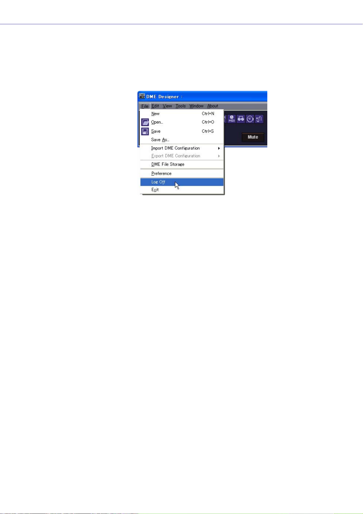
Logging Off
Logoff is used when changing users. When you log off, the document currently being edited is closed,
and the “Log On” dialog box is displayed so you can log on the next user. Log off with the [Log Off]
command on the [File] menu in the Main Panel window.
1 Click the [File] menu ➞ [Log Off] command on the Main Panel window.
Log on the next user in the “Log On” dialog box.
Automatic Logging On
With the auto-logon function, you can have a specified user automatically logged on when the
application is started. If you enable the auto-logon feature, the specified user will be logged on when
the application is started, without displaying the “Log On” dialog box.
Auto-logon is set from the “Security” dialog box. See “Security (Creating Users and Making User
Settings)” on page 55.
DME Designer Owner’s Manual
21
Page 22
Chapter 2 DME Designer Overview
Project Files
Project Files
Systems built with DME Designer are saved as project files. Project files have “.daf” as the extension
for their filenames.
These files include settings for the area, zones, configurations, and each parameter.
Since only one project file can be open at a time, before you can open a second file, the first one must
be closed.
The commands for opening project files, creating new ones, and saving them, are found in the [File]
menu of the Main Panel window.
Creating New Project Files
Project files are created using the [File] menu → [New] command in the Main Panel window.
1 Click [File] menu ➞ [New] in the Main Panel window.
Since the currently open project file must be closed before a new one can be created, a “Project
file has been modified. Save?” dialog box will be displayed.
2 To save the file, click [Yes]. To close without saving, click [No].
If you click [Yes], the file currently saved with the same name will be overwritten. If the file has not
been saved, the File Save dialog box will be displayed.
A new project file will be created.
DME Designer Owner’s Manual
22
Page 23
Chapter 2 DME Designer Overview
Saving Project Files
Project files are saved using the [File] menu → [Save] and [Save As] commands in the Main Panel
window. The [Save] command overwrites the previously saved version of the file. The [Save As]
command lets you give a new name to the file before saving it. When you save the file with a new
name, you can protect it with a password.
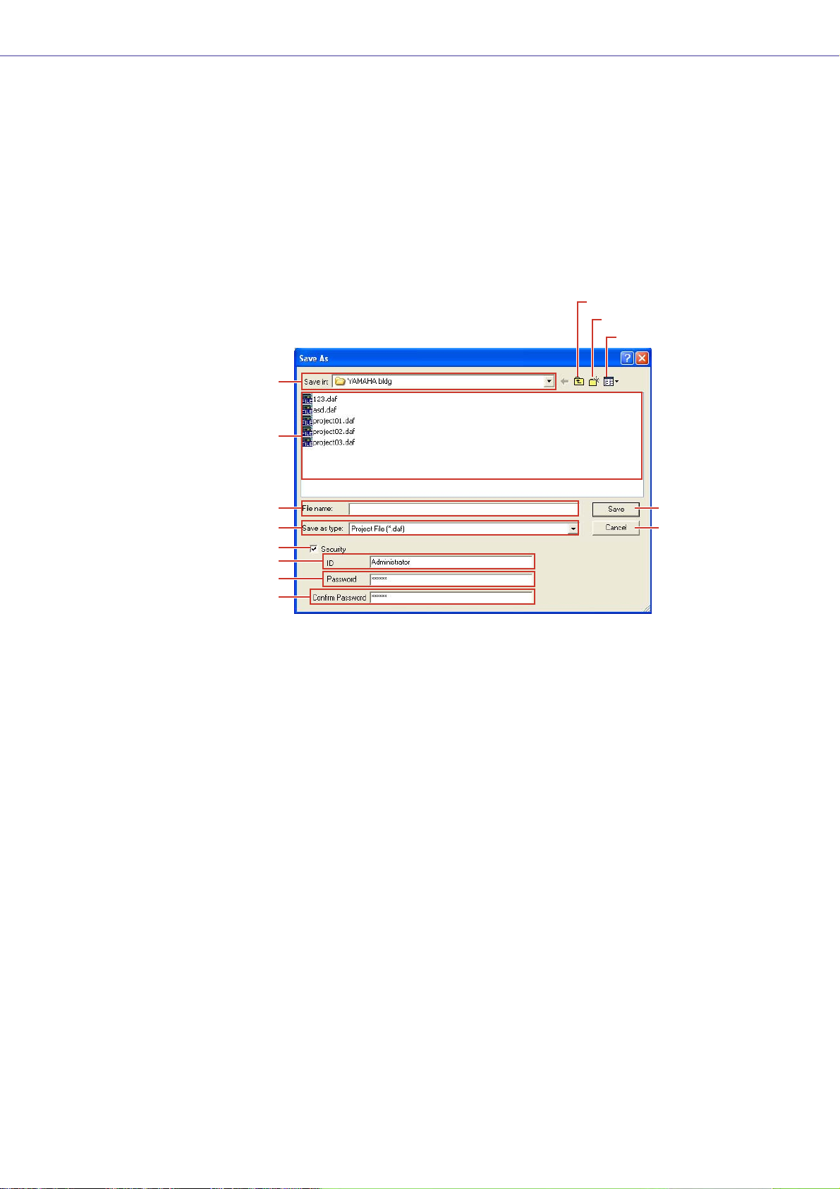
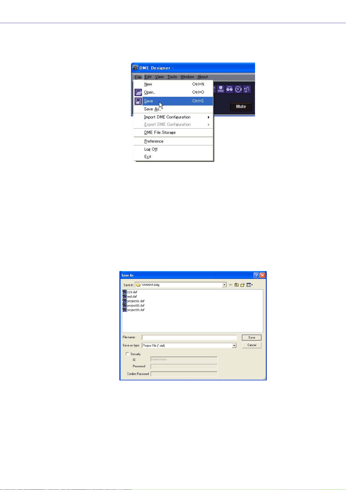
■ The “Save As” Dialog Box
When you click the [File] menu → [Save As] command in the Main Panel window, the “Save As”
dialog box is displayed. Except for some [Security] options, this dialog box is the same as the
normal Windows dialog box for saving files.
[Up One Level] Button
2
[Create New Folder] Button
3
[Views] Button
4
1
5
6
7
@
#
8
9
)
!
1 [Save In]
Specify the folder for saving the file. The folder name is displayed in this box. Click the [▼] on
the right to move to another folder.
The large box below displays the contents of the folder in this box.
2 [Up One Level] Button
Moves to the folder one level higher in the hierarchy.
3 [Create New Folder] Button
Creates a new folder in the folder currently being displayed.
4 [Views] Button
Changes the way the folder content list is displayed. If you click this button, a menu appears
that lets you change the arrangement and display format of the files in the list.
5 List
This box displays the contents of the folder shown in the [Save In] box. Only files belonging to
the type selected in the [Save As Type] box will be displayed.
6 [File Name] Box
Enter the filename. If the currently open file has already been saved, its name will be already
entered in this box. To save using a different filename, change the name here.
DME Designer Owner’s Manual
23
Page 24
Chapter 2 DME Designer Overview
7 [Save as type]
Selects the format for the file you are saving. When saving project files including Wave files set
for Wav File Player, select “Project File with wave (*.daf)”. Otherwise, select “Project File (*.daf)”.
8 [Security]
Protects files with a password. If you check here, you will be able to enter settings in the [ID],
[Password], and [Confirm Password] boxes.
9 [ID] Box
Enter the ID that has been set for the file. The currently logged on user name will be preentered, but you can change it. This need not be the same as a user name.
) [Password] Box
Enter the password that has been set for the file. You can enter up to 256 alphanumeric
characters. The characters you enter will be displayed as asterisks (*) in the [Password] box.
! [Confirm Password] Box
Enter the password once again to confirm it. Enter the same password as was entered into the
[Password] box. The characters you enter will be displayed as asterisks (*), the same as in the
[Password] box.
NOTE
When someone attempts to open a password-protected project file, the application will request an ID and password.
If they are not entered correctly, the file cannot be opened. Be careful to avoid mistakes when entering the ID and
password. The password cannot be reissued and the ID and password cannot be changed. Be careful not to forget
them.
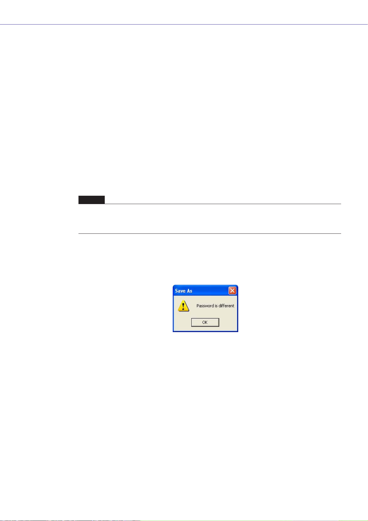
@ [Save] Button
Saves the project file.
If the characters entered into the [Password] and [Confirm Password] boxes were not the same,
a “Password is different” dialog box will be displayed. Click the [OK] button and reenter the
correct password in the [Password] and [Confirm Password] boxes.
# [Cancel] Button
Cancel the file save process.
DME Designer Owner’s Manual
24
Page 25
Chapter 2 DME Designer Overview
■ Saving Project Files
1 Click [File] menu ➞ [Save] in the Main Panel window.
If there is a file already saved with the same name, it will be overwritten.
When saving a project file for the first time, you must name the file before saving it. The “Save
As” dialog box will open, the same as when clicking the [File] menu [Save As] command. Enter
a filename and specify the folder where the file will be saved.
■ Saving a File with a New Name
With the [File] menu [Save As] command in the Main Panel window, you can save the currently
open file with a new filename. When saving for the first time, this creates a new file. A file that has
already been saved with a name will be saved as a separate file.
1 Click [File] menu ➞ [Save As] in the Main Panel window.
The “Save As” dialog box will be displayed.
2 Enter a filename into the [File name] box.
3 Specify the folder where the file will be saved.
4 Click the [Save] button.
DME Designer Owner’s Manual
25
Page 26

Chapter 2 DME Designer Overview
■ Protecting a Project File with a Password
When you save a project file with a new name, you can set a password and protect the file. If a
password is set, an ID and password will be requested when the file is opened.
The security settings for a file cannot be changed by resaving the file with the same name. They
can only be changed when saving the file with a new name using the [Save As] command. Once
set, the ID and password cannot be changed. To change the ID and password for passwordprotected project files, use the [Save As] command to save the file as a new one with a different
name.
1 Click [File] menu ➞ [Save As] in the Main Panel window.
The “Save As” dialog box will be displayed.
2 Place a checkmark for [Security] in the file save dialog box.
3 Enter an ID into the [ID] box.
The name of the currently logged on user will be automatically entered into the [ID] box. To
change it, enter another ID into the box.
When using [Save As] to save a password-protected file, the dialog box will be displayed with
the ID and password boxes automatically filled in with the ID and password that were assigned
to the original file. To change the ID and password, enter new ones into the boxes.
4 Enter the desired password into the [Password] box.
You can enter up to 256 alphanumeric characters for the password. The characters you enter
will be displayed as asterisks (*) in the [Password] box.
5 Enter the same characters into the [Confirm Password] box as were entered into the
[Password] box.
The characters you enter will be displayed as asterisks (*) in the [Password] box.
6 Click the [Save] button.
DME Designer Owner’s Manual
26
When saving a password-protected file without changing the name, the same ID and password
will be set (the ID and password cannot be changed).
Using the [Save] command, you cannot password protect an already saved project file that was
not already password protected. To set a password for a file that is not already password
protected, save it as a separate file using the [Save As] command.
Page 27
Chapter 2 DME Designer Overview
Opening Project Files
Project files are opened using the [File] menu → [Open] command in the Main Panel window. Since
the currently opened project file must be closed before another one can be opened, a “Project file has
been modified. Save?” dialog box may be displayed.
■ [Open] Command
Project files are opened using the [File] menu → [Open] command in the Main Panel window.
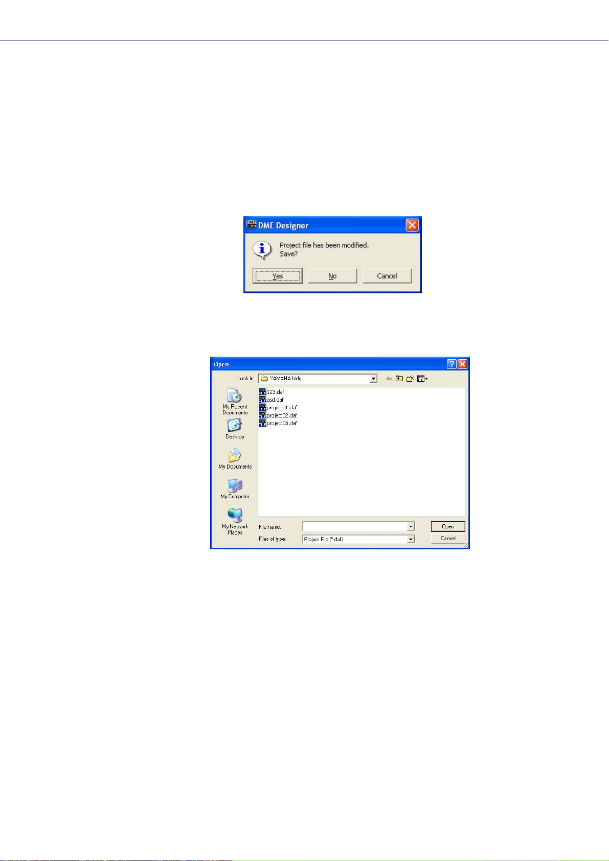
1 Click [File] menu ➞ [Open] in the Main Panel window.
A “Project file has been modified. Save?” dialog box may be displayed.
2 Click the [Yes] or [No] button.
The “Open” dialog box will be displayed.
3 Selects the file to be opened.
4 Click the [Open] button.
DME Designer Owner’s Manual
27
Page 28
Chapter 2 DME Designer Overview
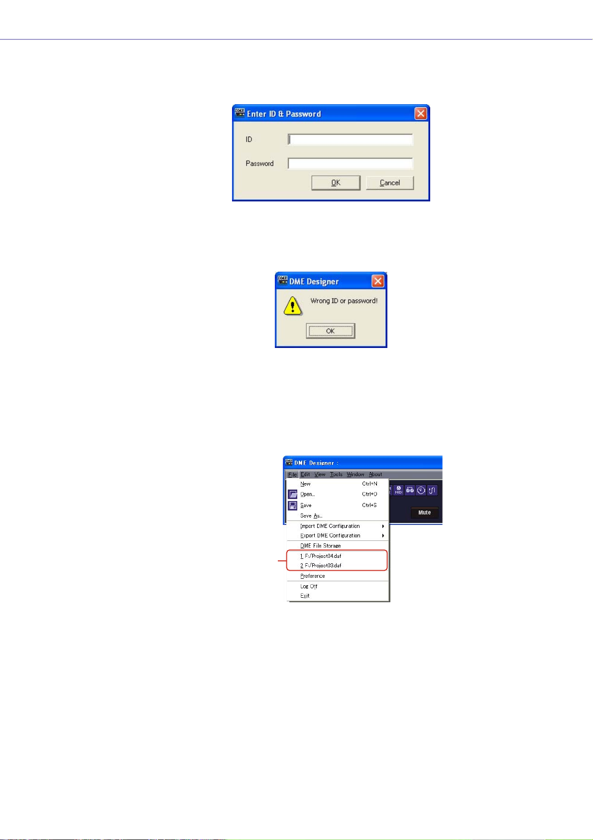
■ Opening a Project File That Has Security Set
If security is set for a project, the “Enter ID & Password” dialog box will be displayed when you
click the [Open] button in the “Open” dialog box.
Enter the ID and password for the file into the [ID] and [Password] boxes, and click the [OK]
button.
If you enter an incorrect ID or password and click the [OK] button on the “Enter ID & Password”
dialog box, the “Wrong ID or password!” dialog box will be displayed.
Click the [OK] button and enter the correct ID and password the “Enter ID & Password” dialog
box.
■ Opening a Project File from the “Recently Used Files” List
Recently used project files are displayed on the [File] menu in the Main Panel window. If you click
one of the filenames, you can open that project file.
Recently Used Files
If security is set for a project file, the “Enter ID & Password” dialog box will be displayed if that file is
selected from the recently used files list. Enter the ID and password to open the file.
DME Designer Owner’s Manual
28
Page 29
Chapter 2 DME Designer Overview
■ Double-Click the Icon for the Project File
When you double-click the icon for the project file, the file will open. If DME Designer is not started,
it will start. After logon, the project file will open.
Just as when you use the [Open] command, if DME Designer is already started, the currently open
project file must be closed before another one can be opened. Therefore, a “Project file has been
modified. Save?” dialog box will be displayed.
NOTE
Sometimes the “Project file has been modified. Save?” dialog box will not be displayed.
If security is set for the project file, the “Enter ID & Password” dialog box will be displayed. Enter
the ID and password to open the file.
Closing Project Files
You cannot have multiple project files open simultaneously in DME Designer. To close the currently
open project file, you can create a new project file or open another project file.
DME Designer Owner’s Manual
29
Page 30
Chapter 2 DME Designer Overview
DME Data File
You can import or export parameters for a DME that is arranged in a configuration file. Parameters for
a single DME unit in the current configuration (the one being edited) are saved as a file. Saved
parameters can be imported into another project file.
Files with parameters saved in them are called “DME Data Files.” These files have “.ddf” as the
extension for their filenames.
DME Data Import
This imports DME data file settings into a DME included in the current configuration.
1 Make active the configuration that arranged the DME into which you are going to import.
If there are multiple configurations, display the window in front for the configuration that arranged
the DME to which you are going to import.
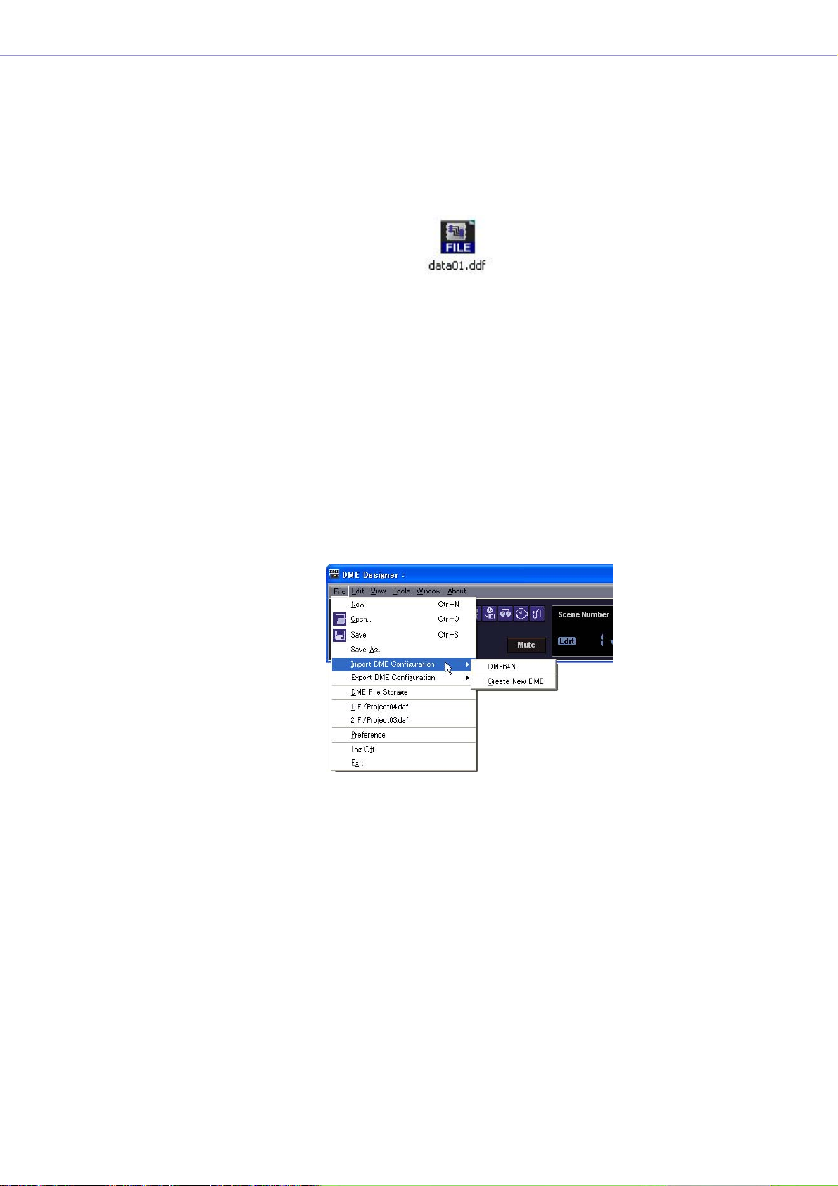
2 Click the [File] menu in the Main Panel window, and move the mouse cursor over [Import
DME Configuration].
A submenu will be displayed. The DMEs included in the current configuration will be displayed on
a submenu.
DME Designer Owner’s Manual
30
Page 31

Chapter 2 DME Designer Overview
3 On the submenu, click on the DME into which you will import settings.
The “Open” dialog box will be displayed.
4 Select the DME data file and click the [Open] button.
■ [Import DME Configuration] Submenu
The DMEs included in the current configuration will be displayed on the [Import DME
Configuration] submenu.
[Create New DME] creates a new DME and imports settings.
NOTE
Only users for whom the [Operation Security] → [Edit] checkbox in the “Security” dialog box has been checked can
import DME data. For information about user security levels, see “Security (Creating Users and Making User Settings)”
on page 55.
NOTE
If DME data file import was not possible, a “DME file import failed.” message will be displayed.
DME Designer Owner’s Manual
31
Page 32

Chapter 2 DME Designer Overview
DME Export
This exports parameters from a DME included in the current configuration and saves them as a file.
1 Make active the configuration that includes the DME from which you will export.
If there are multiple configurations, display the window in front for the configuration that arranged
the DME from which you are going to export.
2 Click the [File] menu in the Main Panel window, and move the mouse cursor over [Export
DME Configuration].
A submenu will be displayed.
3 On the submenu, click on the DME from which you will export settings.
The “Save As” dialog box will be displayed.
4 Enter the filename.
Determines whether a selected file type will be exported along with a wave file.
5 Specify the folder where the file will be saved, then click the [Save] button.
DME Designer Owner’s Manual
32
Page 33

Chapter 2 DME Designer Overview
■ [Export DME Configuration] Submenu
The DMEs included in the current configuration will be displayed on the [Export DME
Configuration] submenu.
DME Designer Owner’s Manual
33
Page 34

Chapter 2 DME Designer Overview
Configuration Creation Procedure
The configuration is a design diagram that determines the DME configuration. Transferring this data
causes the DME to operate. Follow the procedure below to create a DME Designer configuration.
NOTE
Configurations can be created only when the DME unit is offline. To transfer the data, you must first go into online status. The
procedure for going online is given later in this document.
1 Creating a New Project.
When you start DME Designer, a new project is created. If another project file is already open, use
the [File] menu → [New] command in the Main Panel window to create a new file.
“Main Panel Window Menu” → [File] menu → [New] (page 44)
2 Zone Settings.
Zone names are set, and zones are added and deleted using the “Zone” dialog box.
See “Adding, Deleting, and Renaming a Zone” on page 231.
3 Configuration Settings.
Zone names are set, and zones are added and deleted using the “Zone” dialog box.
See “Adding, Deleting, and Renaming a Configuration” on page 233.
4 DME, ICP, External Device Layout.
Arrange DMEs, ICPs, and external devices in the Zone window.
See “Zone Window” on page 237,
“Objects” on page 156,
“Design Window Shared Settings and Operations” on page 207.
5 Placing Components.
Place components and user modules in the Configuration window.
See “Configuration Window” on page 242,
“User Module” on page 250,
“Types of Components” on page 259.
6 Component Logical Connections.
Use wires to connect the components and user modules you placed in the Configuration window.
See “Drawing and Editing Wires” on page 219.
DME Designer Owner’s Manual
34
7 Setting Parameters.
Edit the component parameters in the component editor.
See “Component Editor Window” on page 264.
8 Setting User Defined Parameters.
Parameters can be assigned to function keys F1 through F6 in the DME unit.
See “User Defined Button (User Defined Parameters)” on page 98.
9 Storing Scenes.
Store the scene using the [Tools] menu → [Scene Manager] command in the Main Panel window.
See “Scene Manager” on page 63.
Page 35

Online
Chapter 2 DME Designer Overview
You can connect the DME unit to your computer and transfer configurations, scenes and parameters
created in DME Designer into the DME unit. You can also read data from the DME unit into DME
Designer, synchronizing it with the status of the DME unit.
Because Synchronization presupposes that the DME unit can communicate with the computer where
DME Designer is installed, the necessary drivers (USB-MIDI or DME-N Network Driver) must be
installed, and appropriate settings must be made for each driver and for DME Designer MIDI port.
NOTE
Because there are no scene settings when the DME unit is purchased, the configuration and scene information created in
DME Designer must first be transferred.
1 DME Unit and Computer Connection.
Connect the DME unit and computer using a USB cable or an Ethernet cable.
See separate “DME64N/24N Owner’s Manual” for details.
2 MIDI Driver Installation.
Install the USB-MIDI driver or DME-N Network driver in the computer.
See separate “DME Designer Installation Guide” for details.
3 MIDI Driver Setup.
Make the necessary settings for the MIDI driver installed in the computer. If the driver is set up
already, check the settings before going online.
See separate “DME Designer Installation Guide” for details.
4 MIDI Driver Port Setup.
The MIDI Setup dialog will be displayed if you press the MIDI Setup button on the MIDI Setup
toolbar that is displayed when you start DME Designer Set up the In/Out/Thru ports connected to
the DME.
5 Making MIDI IN/OUT Settings in DME Designer.
On the [Port] tab of the “MIDI” dialog box, select the MIDI driver used for sending and receiving
MIDI messages. If the driver is set up already, check the settings before going online.
“MIDI” → [Port] tab (page 97)
DME Designer Owner’s Manual
35
Page 36

Chapter 2 DME Designer Overview
6 Storing and Checking Scenes.
When moving online, the lowest scene must be stored. You can check if a scene is stored using the
“Scene Manager” dialog box.
See “Scene Manager” on page 63.
7 Recalling Scenes.
When going online, the scene will be recalled. Its scene number must be displayed in [Scene
Number], and its scene name will be displayed in Scene Name. If [--------] is displayed of [Scene
Name], the scene will be recalled.
Main Panel Window → “Current Scene” (page 42)
See “Scene Manager” on page 63.
8 Display the “Synchronization” dialog box.
Click [Synchronization] in the [Tools] menu or the large [Synchronization] button on the toolbar.
When the dialog box opens, a list of connected DME units will be obtained.
DMEs connected to the computer are displayed in the [Network] list.
DME Designer Owner’s Manual
36
NOTE
When requesting the “Synchronization” dialog box, a one-time alert will be displayed if no scene has been recalled, or
the MIDI Port settings have not been made. After clicking the [OK] button on the alert, each dialog will open. At this time,
you can make the needed settings in the displayed dialog box, and then again display the “Synchronization” dialog box.
Page 37

Chapter 2 DME Designer Overview
9 IP Address Selection
The DMEs included in the current zone are displayed in the [Designer] list in the
“Synchronization” dialog box. Click the [IP Address] box, then select the DME unit IP address
that matches the DME currently in the DME Designer.
NOTE
IP addresses are displayed for devices of the same type in the area.
10 Going Online.
Clicking the [Go On-Line] button displays a dialog box where you can decide the synchronization
method.
Click the [Designer→DME] direction button.
Transfer of the configuration will begin, and DME Designer will be synchronized with the unit.
If there are many zones, this process may take time.
DME Designer Owner’s Manual
37
Page 38

Chapter 2 DME Designer Overview
When going online is finished, the [Go On-line] button will be grayed out, and the Main Panel
window [On-Line] button will light up. The dialog box will close automatically if [Close this window
after synchronization] is checked.
NOTE
It may not be possible to go online if a scene has not been stored when [Recall Safe] is selected.
To go off line, click either the [ON-Line] button in the main panel window, or the [Go Off-line]
button in the “Synchronization” dialog box.
DME Designer Owner’s Manual
38
Page 39

Chapter 3 Main Panel Window
Main Panel Window
The Main Panel window is the main window of DME Designer.
Title Bar
Menu Bar
Tool Buttons (Small)
Tool Buttons (Large)
Log On User
[Mute] Button
Current Scene
Current Zone
Communication
Status
Title Bar
“DME Designer” is displayed on the title bar.
Menu Bar
Commands that can be executed in the application are collected into categories on the menu bar.
When you click one of the categories, a list of commands is displayed.
Also, the name of the currently open project file is displayed at the right. When a new project file has
been opened, or has not yet been saved, “Untitled” will be displayed for the file name.
Tool Buttons (Small)
Frequently used commands are arranged here as buttons. When a command cannot be used, its
button will be grayed out.
[Open File] Button
[Save File] Button
[Undo] Button
[Undo History] Button
[Redo] Button
[MIDI] Button
[GPI] Button
[Word Clock] Button
[User Defined] Button
[User Control Manager] Button
[Clock] Button
[Parameter Link] Button
DME Designer Owner’s Manual
39
Page 40

Chapter 3 Main Panel Window
■ [Open File] Button
Opens project files.
→ [Open] on the [File] menu (page 45)
■ [Save File] Button
Saves the project file currently being edited.
→ [Save] on the [File] menu (page 45)
■ [Undo] Button
Undoes the most recent edit operation.
→ [Undo] on the [Edit] menu (page 47)
■ [Undo History] Button
Opens the “Undo History” dialog box. Undoes multiple operations.
→ [Undo History] on the [Edit] menu (page 47)
■ [Redo] Button
Restores operations undone with the [Undo] button back to their original condition.
→ [Redo] on the [Edit] menu (page 47)
■ [User Defined] Button
Opens the “User Defined Button” dialog box.
→ See “[User Defined Button]” on page 49.
■ [Word Clock] Button
Opens the “Word Clock” dialog box.
→ See “[Word Clock]” on page 49.
■ [GPI] Button
Opens the “GPI” dialog box.
→ See “[GPI]” on page 49.
■ [MIDI] Button
Opens the “MIDI” dialog box.
→ See “[MIDI]” on page 49.
■ [Parameter Link] Button
Opens the “Parameter Link” dialog box.
→ See “[Parameter Link]” on page 49.
■ [Clock] Button
Opens the “Clock” dialog box.
→ See “[Clock]” on page 50.
DME Designer Owner’s Manual
40
■ [User Control Manager] Button
Opens the “User Control Manager” dialog box.
→ See “[User Control]” on page 48.
Page 41

Tool Button (Large)
[User Control] Button
Chapter 3 Main Panel Window
[Synchronization] Button
[Event Logger] Button
[Show/Hide Designer] Button
[Event Scheduler] Button
■ [Show/Hide Designer] Button
Displays or hides the Designer window.
■ [User Control] Button
Works the same as the [User Control] command on the [View] menu. Clicking this button displays a
menu.
User Control will be displayed on the menu. If you click there, the user control window will be
displayed.
If you click [New User Control], the “New User Control” dialog box opens.
■ [Synchronization] Button
Opens the “Synchronization” dialog box.
→ See “Synchronization” Dialog Box on page 76.
■ [Event Logger] Button
Opens the Event Logger window.
→ See “Event Logger” Window on page 111.
■ [Event Scheduler] Button
Opens the “Event Scheduler” dialog box.
→ See “Event Scheduler” Dialog Box on page 116.
DME Designer Owner’s Manual
41
Page 42

Chapter 3 Main Panel Window
[Mute] Button
Tur ns ON and OFF the DME mute button for the current zone.
To turn it ON, press the <Shift> key while clicking. If you click the button while it is OFF without
pressing the <Shift> key, the following message will be displayed: “Click the Mute Button with the Shift
Key.”
To turn it OFF, click on the button. There is no need to press the <Shift> key.
Current Scene
Displays the number and name of the current scene. You can switch between scenes.
Mute OFF Mute ON
[Scene Number]
[Scene Name]
[Scene Manager] Button
■ [Scene Number]
Displays the number of the current scene. A list where you can select a scene is displayed when
you press the [▼]. The EDIT indicator will light when a parameter has been edited after recalling or
storing a scene.
NOTE
Press <Ctrl> key and <+> key simultaneously recall the next scene and press <Ctrl> key and <-> key simultaneously
recall the previous scene. These settings can be changed via the Shortcut keys dialog box (page 134).
DME Designer Owner’s Manual
42
■ [Scene Name]
Displays the name of the current scene.
■ [Scene Manager] Button
Opens the “Scene Manager” dialog box.
Page 43

[User] (Logged On User)
Chapter 3 Main Panel Window
Currently Logged On
User Name
[Security] Button
■ Currently Logged On User Name
Displays the currently logged on user name.
■ [Security] Button
Opens the “Security” dialog box.
Current Zone
Displays the name of the active zone. A list where you can select a zone is displayed when you press
the [▼].
Communication Status
Displays the communication status between the DME unit and the computer.
Message T ransmit/Receiv e Indicator
ON-line Button
■ [On-line] Button
When the DME unit is connected to a computer, clicking this button alternately switches the unit's
on-line/off-line status. The indicator will light when the DME unit is on-line.
■ Message T ransmit/Receive Indicators
[Rx]
Lights when MIDI messages from the DME unit are received by DME Designer.
[Tx]
Lights when MIDI messages are transmitted from DME Designer to the DME unit.
DME Designer Owner’s Manual
43
Page 44

Chapter 3 Main Panel Window
Main Panel Window Menu
[File] Menu
■ [New]
Creates a new project. When a new project is created, the current project will be closed.
A confirmation message asking “Project file has been modified. Save?” will be displayed.
[Yes] Button
Saves the currently open project.
If the currently open file was already given a name and saved, that saved file will be overwritten.
The “Save As” dialog box will be displayed for files that have not yet been saved. In this dialog box,
you can name the file when you save it.
[No] Button
Closes the project without saving it. If the file has already been given a name and saved, the most
recently saved version will remain as is. If the project has not been given a name and saved, it will
be lost.
[Cancel] Button
Cancels creation of a new project.
DME Designer Owner’s Manual
44
Page 45

Chapter 3 Main Panel Window
■ [Open]
Opens saved project files. Because the currently open project will be closed, a confirmation dialog
box asking “Project file has been modified. Save?” will be displayed.
When you select this command, the “Open” dialog box will be displayed. Select the project file you
want to open and click the [Open] button.
If security is enabled for the project file, the “Enter ID & Password” dialog box will be displayed.
Enter the ID and password to open the file and click the [OK] button. The project file will open.
■ [Save]
Overwrites an already saved project file with the current changes. If the file is being saved for the
first time, the “Save As” dialog box will be displayed.
→ See “Project Files” on page 22.
■ [Save as]
Saves the current project file as another file with a new name or in a new location. When you select
this command, the “Save as” dialog box will be displayed.
→ See “Project Files” on page 22.
■ [Import DME Configuration]
Imports parameters for a DME that is arranged in a configuration file.
→ See “DME Data File” on page 30.
■ [Export DME Configuration]
Exports parameters of a DME that is arranged in a configuration file.
→ See “DME Data File” on page 30.
■ DME File Storage
Opens the “DME File Storage” dialog box.
→ See “DME File Storage” on page 52.
DME Designer Owner’s Manual
45
Page 46

Chapter 3 Main Panel Window
■ Recently Used Files
Displays recently saved files. If you click one of the file names, you can open that file.
■ [Preference]
Opens the “Preference” dialog box.
→ See “Preferences” on page 53.
■ [Log Off]
Logs off the currently logged on user. Because the currently logged on user must be logged off
before a new one can be logged on, the “Log On” dialog box will be displayed so you can log on
the next user.
→ See “Users and Security” on page 19.
■ [Exit]
Closes “DME Designer.” A confirmation dialog box asking “Project file has been modified. Save?”
will be displayed. To save, click [Yes]. To close without saving, click [No.]
DME Designer Owner’s Manual
46
Page 47

Chapter 3 Main Panel Window
[Edit] Menu
■ [Undo]
Undoes a single operation. The name of the operation that will be undone by [Undo] is displayed in
the command name. You can also select the commands that come after that.
When [Undo] is not possible, the command will be grayed out.
■ [Redo]
Returns to the status before the [Undo] command was executed. The name of the operation that
will be restored by [Redo] is displayed. You can [Redo] only as many operations as were undone
with the [Undo] command. When [Redo] is not possible, the command will be grayed out.
■ [Undo History]
Opens the “Undo History” dialog box. Undoes multiple operations. Also deletes the history of
operations.
1
1 List
Displays all operations performed so far, in order starting with the oldest. You can select an
operation by clicking on it.
2 [OK] Button
Undoes all operations below the one selected on the list. The operation selected on the list does
not get undone.
2
3
4
3 [Close] Button
Closes the dialog box.
4 [Delete All] Button
Deletes the entire history of operations displayed on the list. When an operation is deleted from
the list, it cannot be undone.
Operations undone from the [Undo History] can be re-executed one-by-one using [Redo].
DME Designer Owner’s Manual
47
Page 48

Chapter 3 Main Panel Window
[View] Menu
■ [Designer]
Displays or hides the Designer window.
■ [Event Logger]
Displays the network event log.
Not displayed if selected while the network event log is showing.
→ See “Event Logger” on page 111.
■ [User Control]
This opens User Control.
The user controls that can be opened by the currently logged on user are displayed on a submenu.
If you click [New User Control] on the submenu, the “New User Control” dialog box opens.
→ See “User Control/User Module Editor” on page 279.
NOTE
Controls that are not available to the currently logged-on user are not shown in the menu.
[Tools] Menu
DME Designer Owner’s Manual
48
■ [Scene Manager]
Opens the “Scene Manager” dialog box.
→ See “Scene Manager” on page 63.
Page 49

Chapter 3 Main Panel Window
■ [User Control Manager]
Opens the “User Control Manager” dialog box.
→ See “User Control” on page 70, page 279
■ [Parameter Link]
Opens the “Parameter Link” dialog box.
→ See “Parameter Link” on page 73.
■ [Synchronization]
Opens the “Synchronization” dialog box.
→ See “Synchronization (DME Designer and DME Unit Synchronization)” on page 75.
■ [Event Scheduler]
Opens the “Event Scheduler” dialog box.
→ See “Event Scheduler” on page 116.
■ [Wav File Manager]
Opens the “Wav File Manager” dialog box.
→ See “Wav File Manager” on page 128.
■ [GPI]
Opens the “GPI” dialog box.
→ See “GPI” on page 79.
■ [MIDI]
Opens the “MIDI” dialog box.
→ See “MIDI” on page 90.
■ [User Defined Button]
Opens the “User Defined Button” dialog box.
→ See “User Defined Button (User Defined Parameters)” on page 98.
■ [DAW Control]
Opens the “DAW Control” dialog box.
→ See “DAW Control” on page 132.
■ [Remote Control Setup List]
Opens the “Remote Control Setup List” Dialog box.
→ See “Remote Control Setup List” on page 123.
■ [Word Clock]
Opens the “Word Clock” dialog box.
→ See “Word Clock” on page 102.
■ [Monitor]
Opens the “Monitor Out” dialog box.
→ See “Monitor” on page 104.
DME Designer Owner’s Manual
49
Page 50

Chapter 3 Main Panel Window
■ [Clock]
Opens the “Clock” dialog box.
→ See “Clock” on page 105.
■ [Language]
Opens the “Language” dialog box.
→ See “Language Settings” on page 106.
■ [Parameter List]
Opens the “Parameter List” dialog box.
→ See “Parameter List” on page 124.
■ [Component Lock]
Opens the “Component Lock” dialog box.
→ See “Component Lock” on page 127.
■ [Security]
Opens the “Security” dialog box.
→ See “Security (Creating Users and Making User Settings)” on page 55.
■ [Shortcut Keys]
Opens the “Shortcut Keys” dialog box.
→ See “Shortcut Keys” on page 134.
■ [Backup]
Opens the “Backup” dialog box.
→ See “Backup” on page 135.
■ [Firmware Update]
Updates the DME unit firmware.
→ See “DME Firmware Update” on page 107.
DME Designer Owner’s Manual
50
Page 51

Chapter 3 Main Panel Window
[Window] Menu
Displays the open windows. Click a window name to bring that window to the front.
■ [Close All Editor Windows]
Closes all editor windows.
NOTE
Each design windows within the Designer window can be switched using the [Window] menu in the Designer window.
[About] Menu
■ [About DME Designer]
Displays information about this application.
DME Designer Owner’s Manual
51
Page 52

Chapter 3 Main Panel Window
DME File Storage
Allows management of DME files. Project files can be managed on the DME, eliminating the need to
manage them on the computer.
Click [DME File Storage] in the [File] menu to display the “DME File Storage” dialog.
■ Zone List
Select the desired zone and DME from the list.
■ File List
A list of the files stored on the selected DME.
[Send] Button
Transfers selected files from the computer to the DME.
[Receive] Button
Transfers selected files from the DME to the computer.
[Delete] Button
Deletes selected files from the DME.
NOTE
Synchronization may become impossible if the [Remaining Memory] value (the amount of remaining DME memory)
becomes too small. If this occurs, delete unwanted files to increase the amount of available memory.
DME Designer Owner’s Manual
52
Page 53

Preferences
When you click the [Preference] command on the [File] menu in the Main Panel window, the
“Preferences” dialog box is displayed. Here you can make environmental settings for using DME
Designer.
■ [Application] T ab
Here you can set the general usage environment.
Chapter 3 Main Panel Window
On Startup
Selects the action when the application starts up.
• [Load the last file opened]
Opens the last opened file. If the file cannot be found because it was moved, deleted, or its
name was changed, a new project will be opened.
• [Create an empty file]
Opens a new project.
• [Load File & Synchronization]
Opens the last opened file and synchronizes with the DME unit.
Contents Folder
Specifies the folder where the images used by the Design windows and user controls are stored.
Click the [Browse] button and specify the folder.
Auto Save
Set up the automatic file save feature.
• [Enable]
Auto save of project files being worked on will occur when checked. The file will be
overwritten, but the Undo history will not be cleared. This setting has no effect when the file
being worked on has not previously been saved, or the computer is online.
• [Interval in minutes]
Specifies the auto-save interval in minutes.
DME Designer Owner’s Manual
53
Page 54

Chapter 3 Main Panel Window
[Confirm Scene Store]
Place a checkmark here to have a confirmation dialog box displayed when storing a scene.
[Save after synchronization]
If a save is performed after the DME Designer is synchronized to the DME unit, the next
synchronization will be significantly faster because one the difference needs to be synchronized.
Check this checkbox to specify auto-save after the DME Designer is synchronized to the DME unit.
■ [Component Editor] Tab
Sets up operation of the Component Editor knobs, sliders, and edit boxes. Refer to “Changing
Parameters” on page 266.
DME Designer Owner’s Manual
54
Page 55

Chapter 3 Main Panel Window
Security (Creating Users and Making User Settings)
When you click the [Security] command on the [Tools] menu, the “Security” dialog box is displayed.
Here you can create and delete users. You can also set the security level for each user. Users are
saved as DME Designer settings. You don’t need to create users for each file.
Auto-Logon User
■ User Setting Restrictions
Various restrictions apply, depending on the security level of the user that is currently logged on.
• The currently logged on user can edit only users at a security level lower than his or her own.
• The currently logged on user cannot raise his or her own security level.
■ [Administrator] User
The [Administrator] user is registered by default, and can use all functions. Immediately after DME
Designer is installed, there is no password set for the [Administrator] user.
DME Designer Owner’s Manual
55
Page 56

Chapter 3 Main Panel Window
■ Security Level
User security levels are set with the [Operation Security] item at the right of the “Security” dialog
box.
Level 1 User
Level 2 User
Level 3 User
Level 4 User
User Level
High
Low
Security Level Settings
You can allow or disallow editing and the ability to open windows or set controls.
Ten levels, 1 through 10, are set for scene storage/recall and user controls. Level 1 is the highest
level and 10 is the lowest. By default, level 1 is set for the [Administrator] user. Level 1 can be set
for the [Administrator] only. Users created by the [Administrator] directly below itself can be set at
levels 2 through 10. New users created subordinate to users at level 2 can be set at levels 3
through 10. New users can be created no higher than one level below the user that created them.
Scene sets the level for storing and recalling scenes. The logged on user can store or recall scenes
at levels equal to or lower than his or her own level. For example, a user at level 3 can recall scenes
set for scene recall at levels 3 through 10.
Levels are also set for user control. The logged on user can display or edit user controls at levels
equal to or lower than his or her own level.
The log-on user can use zones that are checked in the [View Zone] field.
DME Designer Owner’s Manual
56
Page 57

Chapter 3 Main Panel Window
[Enable Auto-Log On]
Enables auto-logon. If this checkbox is selected, the user displayed in the box to the right will be
logged on automatically when DME Designer is started. Auto-logon logs on the user without any
password entry.
Click the [▼] at the right of the box, and select the user for auto-logon from the displayed user list.
If auto-logon is turned OFF, the “Log On” dialog box will be displayed whenever the DME Designer is
started. Each time a user must be selected and a password entered in order to log on.
If auto-logon is changed from ON to OFF when a password is set for the currently logged on user, a
“Confirmation of Current User” dialog box will be displayed.
Enter the user’s password into the [Password] box, and click the [OK] button.
If you click the [Cancel] button, auto-logon will remain ON.
■ Auto-Logon User
Selects the user for auto-logon when [Enable Auto Log On] is checked.
The currently logged on user can set this command for users at a security level equal to or lower
than his or her own. If a user at a higher level is selected, a message that warns “Cannot access
higher user level.” will be displayed. Click the [OK] button.
To set auto-logon for a user at a security level higher than the currently logged on user, first log off
as the current user, then logon as a user at a higher security level.
DME Designer Owner’s Manual
57
Page 58

Chapter 3 Main Panel Window
User List
The registered users are displayed here. The currently logged on user is displayed in bold text. Click
the name of the user whose settings you want to edit.
21
6
3
4 5
The [Administrator] is the user set by default, and it is used for administering the system. The
[Administrator] user has the highest level and can use all functions.
All new users are created at a level lower that the [Administrator] user, and are displayed below the
[Administrator].
If a user at level 2 and below has other users subordinate to him or her, a [+] or [-] button will be
displayed to the left of higher level user’s name on the list. Clicking the [+] or [-] buttons displays or
hides the users subordinate to that higher user.
The currently logged on user can create multiple users at lower levels.
1 Name
Displays the user names. The currently logged on user is displayed in bold text.
2 Startup User Control
Displays “ON” to automatically open the user control and make settings when the user is logged
on.
3 [Add User] Button
Adds a user subordinate to the user selected on the list. Clicking here displays the “Add User”
dialog box. Select the user that will be superior to the new user, then click this button.
If a user higher than the currently logged on user is selected, the button will be grayed out and
no user can be added.
DME Designer Owner’s Manual
58
4 [Remove User] Button
Deletes the user selected on the list. Only users at levels lower than the currently logged on user
can be deleted.
Furthermore, the currently logged on user cannot delete himself.
5 [Change] Button
Changes settings for the user selected on the list. Opens the “Change User Information” dialog
box. The contents of the dialog box are the same as the “Add User” dialog box.
Page 59

Chapter 3 Main Panel Window
6 Operation Security
Sets the functions that can be used by the user selected on the [User List] to the left. Selecting
a checkbox enables use of the corresponding function.
• [Edit]
You can change the following settings: editing in the Designer window, user control edit, user
defined parameter edit, word clock, scene edit, GPI and MIDI.
• [View DME Design Window]
Allows display of the Designer configuration window.
• [Control Component Editor]
Allows parameter editing in the component editor.
• [View Component Editor]
Allows display of the component editor.
• [Change Configuration]
Allows switching between configurations.
• [Synchronization]
Allows synchronizing with the DME unit.
• [View Log Window]
Displays the Event Logger window.
• [Scene Store/Recall Level]
Sets the level at which scenes can be stored and recalled. Click the [▲] and [▼] buttons or
enter a number into the box to set the level. While levels 1 through 10 are available, the range
of levels that can be actually set varies according to the level of the user doing the setting.
When a user is created, automatically this is set to “One level lower than the user above.” The
initially set level is the highest level that can be set for that user.
• [User Control Level]
Sets the user control level. Click the [▲] and [▼] buttons or enter a number into the box to set
a level from 1 through 10. While levels 1 through 10 are available, the range of levels that can
be actually set varies according to the level of the user doing the setting.
When a user is created, automatically this is set to “One level lower than the user above.” The
initially set level is the highest level that can be set for that user.
DME Designer Owner’s Manual
59
Page 60

Chapter 3 Main Panel Window
“Add User” Dialog Box/“Change User Information” Dialog Box
When you click the [Add User] button in the “Security” dialog box, the “Add User” dialog box is
displayed. If you click the [Change] button in the “Security” dialog box, the “Change User Information”
dialog box is displayed.
The “Add User” dialog box is for setting a user name and password when adding a new user. You can
change user settings in the “Change User Information” dialog box. The contents of the dialog boxes
are the same.
■ [Name] Box
Enter the user name. Enter a name different than other existing user names.
“Add User” dialog box “Change User Infor mation” dialog box
■ [Password] Box
Enter the password. When you type in the password box, asterisks (*) will be displayed instead of
the characters you enter. If you do not want to set a password the user, leave the box blank.
■ [Confirm Password] Box
Enter the password once again to confirm it. When you type in the password box, asterisks (*) will
be displayed instead of the characters you enter. If you do not want to set a password the user,
leave the box blank.
■ [Startup User Control]
When a user logs on, user controls and settings which are specified or below that user’s security
level are automatically opened.
In the “Security” dialog box [User List], [User Control] will be “ON” for users for whom this option
has been turned on.
■ [OK] Button
In the “Add User” dialog box, this creates new users according to the settings made there. In the
“Change User Information” dialog box, this applies the dialog box settings and changes the user
settings.
DME Designer Owner’s Manual
60
■ [Cancel] Button
Cancels user creation or setting changes, and closes the dialog box.
Page 61

Chapter 3 Main Panel Window
Creating Users
Users are created as follows:
1 Click [Security] on the Main Panel window [Tools] menu.
The “Security” dialog box will be displayed.
You can open the “Security” dialog box by clicking the [Security] button in the Main Panel window.
2 Select a user from the [User List] in the “Security” dialog box.
A user will be created subordinate to the selected user. [Administrator] can be selected only if the
logged on user is the [Administrator]. If there are multiple users, select the user that will be above
the new user.
Multiple users can be created subordinate to a single user.
3 Click the [Add User] button.
The “Add User” dialog box will be displayed.
4 Enter the user name into the [Name] box.
5 Enter the password into the [Password] box.
You can also create users with no password. If you do not want to set a password for the user,
leave the [Password] box blank.
6 Enter the password into the [Confirm Password] box also.
If you do not want to set a password for the user, leave the [Confirm Password] box blank also.
DME Designer Owner’s Manual
61
Page 62

Chapter 3 Main Panel Window
7 Set the [Startup User Control].
NOTE
If the text entered into the [Password] and [Confirm Password] boxes is not the same, a “Different password!” message
will be displayed. Click the [OK] button and reenter the correct password in the [Password] and [Confirm Password]
boxes in the “Add User” dialog box.
8 Click the [OK] button.
This closes the “Add User” dialog box. The new user will be added to the “Security” dialog box list.
9 Set the security level for the user, using [Operation Security] in the “Security” dialog box.
When creating a new user, all the checkboxes in [Operation Security] will be turned OFF. Click and
turn ON the functions you want to permit the new user to use. [Scene Store/Recall Level] and [User
Control Level] will be set to one level lower than the user above the newly created user. The initially
set level will automatically be the highest level that can be set for that user. To lower the level, enter
a larger number in the box.
Click the [OK] button and the dialog will close. You can continue creating new users without
closing the dialog box.
DME Designer Owner’s Manual
62
Page 63

Scene Manager
Scenes
Configuration contents can be given a name and saved as “Scenes.” Saving scenes is called “Scene
Store.” Parameter settings in the configuration for each site used can be stored multiple times and
recalled and used when needed. There are 999 scene memories available. When a scene is stored,
DME parameters are saved as “preset parameters.” Presets are automatically created when a scene
is stored.
Bringing back a scene (making a scene the current scene) is called “scene recall.” Scenes are
recalled using the [▼] button next to the current scene on the Main Panel window or by using the
“Scene Manager” dialog box.
■ Security for the Logged On User
The currently logged on user can store, recall, or edit scenes that have a security level equal to or
lower than his or her own. User security levels are set with the [Edit] → [Store/Recall/Edit] item in
the “Security” dialog box.
Chapter 3 Main Panel Window
“Scene Manager” Dialog Box
When you click [Scene Manager] in the [Tools] menu, the “Scene Manager” dialog box is displayed.
[Copy] Button [Insert] Button
[Cut] Button
[Paste] Button
List
[Clear] Button
[Store] Button
[Recall Safe] Button
[Detail] Button
[Recall] Button
DME Designer Owner’s Manual
63
Page 64

Chapter 3 Main Panel Window
■ List
Displays the contents of the scene.
Scene No.
Displays the scene number. There are 999 scene memories available. Click here to select a scene.
Name
Displays the name of the scene. Click the [Name] box to enter a scene name. Up to 18 characters
can be entered.
If the scene has not been stored, “[No Data]” will be displayed. A name can be entered when a
scene is stored. The default names are “Scene001,” “Scene002,” etc. The three-digit number is the
same as the scene number (displayed in [Scene Number]) for the stored scene.
Configuration
Displays the configuration name. If the scene has not been stored, a hyphen (-) will be displayed.
Edit Security
Displays the scene edit security levels. Clicking here will display a list where you can change these
security levels. Only levels at or below the security level of the currently logged on user are
displayed in the list. When a user is created, these settings are the same as the new user's security
level, but scene store and edit settings can be set lower.
Recall Security
Displays the scene recall security level. Clicking here will display a list where you can change the
security level. Only levels at or below the security level of the currently logged on user are
displayed in the list. When a user is created, these settings are the same as the new user's security
level, but the scene recall setting can be set lower.
Fade
Fade is used when Fader components are used in a configuration. It sets whether fade is applied
(ON) or not (OFF) when a scene is recalled.
NOTE
The fade function cannot be simulated in DME Designer.
DME Designer Owner’s Manual
64
Page 65

Chapter 3 Main Panel Window
Fade Mode
Sets the fade mode. You can select “All” or “Selected.”
If you select “All,” all channels using Fader components in their configuration will be affected. Even
when multiple components are used, all channels are targeted. If you select “Selected,” the only
channels affected will be those for which the Fade switch in the component editor has been set to
ON.
NOTE
The Fade switch for each channel is set to OFF by default. The fade effect will not be applied, even if Fade=ON and
Fade Mode=Selected is selected. To apply the effect, you must set the Fade switch to ON for the channels where you
need it.
Fade Time
Sets the fade time: i.e. the time it will take fader and pan parameters to reach their new settings
when a scene is recalled. The changes are smooth and continuous. If only the presets in the
recalled scene are set when that scene is recalled, the volume will be adjusted while the sound
from the previous scene is playing, until the new level is reached If the configuration also changes,
the volume will rise from silence until it reaches the new value. This can be set from zero to 60
seconds, in 0.1 second increments.
NOTE
Right-click in the list and use the contextual menu that appears to set User Defined Button, Program Change, GPI In, or GPI
Out for the scene.
■ [Cut] Button
Cuts the scene selected on the list.
■ [Copy] Button
Copies the scene selected on the list.
■ [Paste] Button
Pastes the contents of the cut or copied scene into the scene selected on the list. The selected
scene will be overwritten. If no scene has been cut or copied, the button will be grayed out and
cannot be used.
DME Designer Owner’s Manual
65
Page 66

Chapter 3 Main Panel Window
■ [Insert] Button
Inserts the contents of the cut or copied scene into the location of the scene selected on the list.
The selected scene and those below are moved down by one. For example, if “Door_Open” was
stored as scene number “005,” and selected when the [Insert] button was clicked, the inserted
scene would become scene number “005,” and “Door_Open” would be moved to scene number
“006.”
If no scene has been cut or copied, the button will be grayed out and cannot be used.
If a scene is stored in the lowest scene on the scene memory list (with the scene number [999]), the
button will be grayed out and the insert function will not be available. Delete the contents of scene
number 999 before attempting to use the insert function.
Click the
[Insert] button
NOTE
Move the scene data to a different scene memory when you don’t want to erase the contents of Scene No. 999.
■ [Clear] Button
Deletes the contents of the scene selected on the list.
If the presets included in a scene are not used in another scene, a “Delete preset?” message will
be displayed.
If the presets are not needed, click the [OK] button. If you click the [Cancel] button, the presets will
not be deleted. Whichever you click, the scene itself will be deleted.
NOTE
The [Cancel] button on the “Delete Preset?” message does not cancel the [Clear] for the scene. It merely cancels
deletion of the presets.
DME Designer Owner’s Manual
66
Page 67

Chapter 3 Main Panel Window
■ [Recall Safe] Button
Before performing a recall, you can check the contents of the scene selected on the list, and set
components that will not be read. This is used when there are components you do not want
changed by the scene recall.
When you click this button, the “Recall Safe” dialog box will be displayed.
Component NameCheckbox
All components included in the scene will be displayed. There is a checkbox to the left of each
component. Place a check next to the components you do not wish to have read by scene recall
(those you do not wish changed from their current status).
Press the [Select All] button to check all components, or the [Clear All] button to clear the checks
from all components.
Click the [OK] button. The dialog box will close and when the scene is recalled, all components,
except those checked, will be read.
NOTE
The components checked in the “Recall Safe” dialog box are the components that will not be read (that will be ignored).
If you want to read all components, there is no need to make settings in the “Recall Safe” dialog box.
“Recall Safe” is used when you want to keep some components with their current settings, while there are other
components you want to change according to the scene.
■ [Store] Button
Stores the contents of the current configuration into the scene selected in the list. If an empty scene
is selected and the contents stored there, a new scene is created. If a scene is already stored in
the selected scene number, it will be overwritten. If [Confirm Scene Store] is checked on the
[Application] tab of the “Preferences” dialog box, a confirmation dialog box will be displayed
before the scene is stored.
NOTE
The currently logged on user can store scenes at a security level equal to or lower than his or her own only.
NOTE
When the computer and DME unit are online, a scene stored in the DME Designer will also be stored on the DME unit,
regardless of the DME settings.
The DME utility display Misc. page [Scene Store] setting only affects store operation from the DME panel controls.
When a scene is stored, the configuration parameters at that time are saved as “preset
parameters.” Presets are created automatically.
DME Designer Owner’s Manual
67
Page 68

Chapter 3 Main Panel Window
■ [Recall] Button
Recalls the scene selected in the list and makes it the current scene.
NOTE
The currently logged on user can recall scenes at a security level equal to or lower than his or her own only.
■ [Detail] Button
Expands the dialog box and displays a preset list. If you click the preset list while it is displayed,
the preset list will be hidden. When the dialog box is opened, its status will be the same as the last
time it was closed.
[Del] Button
[Store] Button
[New] Button
[Del Unused] Button
DME
Preset
DME
Preset
[Detail] Button
Preset List
■ Preset List
Displays the presets for each DME unit in the scene selected in the list. When another scene is
selected on the list, the contents of the preset list will be changed.
You can change the presets used in the scene by clicking the radio buttons to the left of the preset
names. You can also create, delete, and store presets or change their names.
DME
Displays the DME. Below the DME are [Slot], [Component], and [AD]. If there are presets below
them, a [+] button will be displayed. When you click the [+] it becomes a [-] and the presets are
displayed.
DME Designer Owner’s Manual
68
Preset
Displays DME presets.
If you click the preset name, selecting the text that is there, you can change the preset name. When
presets are automatically created when a scene is stored, they are named “Preset001,”
“Preset002,” and so on. Presets created with the [New] button are named “New Preset.”
You can select the presets used in a scene by clicking the radio buttons to the left of the preset
names.
Page 69

Chapter 3 Main Panel Window
■ [Del] Button
Deletes the preset selected on the preset list.
NOTE
Presets used in a scene cannot be deleted.
■ [Store] Button
Stores the current parameter status in the preset selected in the preset list. The contents of the
selected preset will be overwritten.
■ [New] Button
Stores the current status and creates a new preset. The newly created preset is named “New
Preset.”
■ [Del Unused] Button
Deletes presets that are not used by DMEs included in the current zone.
NOTE
There is no [OK] button or [Cancel] button in the “Scene Manager” dialog box. To close the dialog box, click the [Close]
button at the upper-right of the dialog box.
Changes from storing/recalling scenes or editing, such as changing names or contents, will be applied immediately.
With the dialog box open, you can make the Designer window active and add components or change parameters.
DME Designer Owner’s Manual
69
Page 70

Chapter 3 Main Panel Window
User Control
User Controls
You can create an original control by arranging knobs and sliders in the component editor. Controls
you create are called “user controls.”
Those created user controls are displayed in the [View] → [User Control] submenu in the Main Panel
window
■ Security for the Logged On User
The currently logged-on user can create and edit the user controls of all users at lower security
levels as well as the controls specified for that user. Available user controls are displayed in the
User Control manager dialog box that can be accessed through the [User Control] sub-menu of the
main panel window [View] menu.
The user control security level for each user is set with [Operation Security] → [User Control Level]
in the “Security” dialog box. For information about user security, see “Security (Creating Users and
Making User Settings)” on page 55.
“User Control Manager” Dialog Box
When you click [User Control Manager] on the [Tools] menu, the “User Control Manager” dialog box is
displayed. This dialog box displays a list of user controls included in the configuration of the current
zone. There they can be created or deleted. You can also edit the name and security level of user
controls here.
NOTE
Only controls available to the currently logged on user are shown in the list.
DME Designer Owner’s Manual
70
Page 71

Chapter 3 Main Panel Window
■ User Control
Displays the names of the user controls. Clicking here will select the characters in the name,
allowing you to change it.
■ Security Level
Displays the security level set for each user control.
Clicking here will display a list where you can change the security level.
■ User
Displays the name of the user specified in User Control.
Clicking here will display a list of the available users.
NOTE
Levels at or below the security level of the currently logged on user are displayed in the list.
DME Designer Owner’s Manual
71
Page 72

Chapter 3 Main Panel Window
■ [New] Button
Creates new user controls. Clicking here displays the “New User Control” dialog box.
Enter the User Control name in the [Name] box.
■ [User Level]/[User Name]
Use the radio buttons to the left to select security-level or user dependent control.
[User Level]
Select a security level from the drop-down list.
[User Name]
Check a checkbox.
Click [OK] to create the specified User Control setup.
■ [Delete] Button
Deletes the user control selected on the list.
■ [OK] Button
Accepts the changed settings and closes the dialog box.
■ [Cancel] Button
Closes the dialog box without changing the settings.
DME Designer Owner’s Manual
72
Page 73

Parameter Link
About Parameter Links
You can group parameters of the same type and link them. These groups are called “Parameter
Links.” When one parameter in a group is changed, all parameters in the group will change in the
same way.
There are two parameter link types: global links and local links. Global links link parameters for DMEs
within a zone. Local links link parameters that are included for a single DME.
NOTE
Parameters can not apply to multiple groups.
Groups can be created and parameters added to groups in the user control/user module control
editor and component editor. For information about creating parameter links, see “Creating Parameter
Links” on page 314.
You can check the status of parameter links and edit them in the Parameter Link window.
Chapter 3 Main Panel Window
Parameter Link Window
When you click [Parameter Link] in the [Tools] menu, the “Parameter Link” window is displayed. You
can also display the window by selecting [Open Parameter Link] from the context menu displayed in
the user control/user module editor and component editor.
[Global Link] button/[Local Link] button
Parameter Link Mode
1 [Global Link] button/[Local Link] button
Switches the window display.
• Global Link
Links to the parameters of multiple DME units in the zone.
• Local Link
Links to the parameters of one DME unit.
NOTE
Because there is a large load on the network, the maximum number of Global Links will be limited to eight.
DME Designer Owner’s Manual
73
Page 74

Chapter 3 Main Panel Window
2 Parameter Link Mode
Parameter linking is active when checked. Uncheck to temporarily disable parameter linking.
Uncheck when you want to adjust the parameters individually.
You can also turn parameter link mode ON or OFF using the context menu in the user control/
user module editor or component editor.
• Group List
Displays a hierarchical list of groups and the parameters that belong to them.
When a group name is selected, the controls that belong to that group are selected.
•Keep Offset (Group icon)
Tur ns ON or OFF whether the offset value set for each parameter is retained as it is. When ON
is set for a group, the Keep Offset icon is displayed in orange. When OFF is set for a group, it
is displayed in green.
When Keep Offset is set to ON and any parameter within the group goes to the minimum or
maximum value, the parameters cannot be further changed.
Keep Offset can be set to ON or OFF using the “Keep Offset” item on the context menu that is
displayed when you right click the name of a group.
• Group Name
You can select a group name by clicking on it. Clicking the selected group name again will
select the characters in the name, allowing you to change it.
Clicking the plus (+) or minus (-) sign to the left of the group name displays or hides items that
belong to that group.
You can delete a group by selecting it and pressing the <Delete> key. You can also delete a
group by right-clicking on the group name and selecting [Delete] in the context menu that is
displayed.
• DME Icon
Displays the DME that includes the parameters that belong to a group. The components can
be displayed or hidden by clicking the plus (+) or minus (-) signs for the DME icon. The
parameters, Min, and Max can be displayed or hidden by clicking the plus (+) or minus (-)
signs for the component.
•Parameter
Displays the parameters that belong to a group. You can display or hide minimum and
maximum values for a parameter by clicking the plus (+) or minus (-) signs.
You can delete a parameter from a group by selecting the parameter name and pressing the
<Delete> key.
DME Designer Owner’s Manual
74
Page 75

Chapter 3 Main Panel Window
Synchronization
(DME Designer and DME Unit Synchronization)
The DME unit and DME Designer are synchronized by Synchronization. The DME operates according
to the configuration and scene information transferred during this process.
This Synchronization is used when transferring the configuration in DME Designer and when
controlling the DME unit in real time.
NOTE
Because Synchronization presupposes that the DME unit can communicate with the computer where DME Designer is
installed, the necessary drivers (USB-MIDI or DME-N Network Driver) must be installed, and appropriate settings must be
made for the driver and for DME Designer MIDI IN/OUT (page 90).
For information about driver installation and settings, see the installation guide. For DME Designer communications settings,
see “Online” (page 35).
NOTE
Because there are no scene settings when the DME unit is purchased, the configuration and scene information in DME
Designer must first be transferred.
NOTE
For information about the online procedure, see “Online” (page 35).
Online and Offline
When a DME unit is connected to the computer and synchronized with DME Designer, its status is
called “Online.” When a DME unit is not physically connected to the computer or is not synchronized
even when it is connected, its status is called “Offline.” You can check the online/offline status and
message transmission in [Communication Status] in the Main Panel window.
■ Online
Sends configurations created in DME Designer to the DME unit and reads data from the DME unit,
so that the DME unit configuration is reflected in the DME Designer configuration. You can also
control the DME in real time from DME Designer. Operations performed in the DME Designer
control editor are reflected in the DME unit, and operations on the DME side are reflected in DME
Designer.
You can not perform configuration editing using the Designer while online.
■ Offline
The communication status becomes offline when editing configurations.
■ Switching Between Online and Offline
You can switch between online and offline in the “Synchronization” dialog box.
NOTE
For information about the online procedure, see “Online” (page 35).
DME Designer Owner’s Manual
75
Page 76

Chapter 3 Main Panel Window
“Synchronization” Dialog Box
When you click the [Synchronization] command on the [Tools] menu, the “Synchronization” dialog box
is displayed. The data from the current zone in the Designer is synchronized with the DME unit.
Here you can make settings for synchronizing the unit in DME Designer one-on-one with the DME that
actually exists on the network.
[Go On-line] Button
[Go Off-line] Button
[Designer]
Message Area
[Network]
DME Designer Owner’s Manual
76
[Close this window after synchronization] checkbox
Page 77

Chapter 3 Main Panel Window
■ [Go On-line] Button
This button will be grayed out when the software is online.
Clicking the button displays a dialog box where you can decide the synchronization method.
[Designer→DME] button
A consistency check is performed between the data in the current zone and the DME data, then
the communication status changes to online. Transmits data from the DME Designer to the DME
unit and synchronizes the two.
[Designer←DME] button
Data from the DME unit is read into DME Designer. Current data stored in the DME unit, such as
scenes, are read into DME Designer. This assumes that the configurations in the DME unit and the
DME Designer agree.
■ [Go Off-line] Button
Clicking this button changes from online to offline. While offline, this button will be grayed out.
■ [Close this window after synchronization] Checkbox
When this checkbox is checked the dialog window will close automatically after synchronization.
■ Designer
The Designer list displays DME units arranged in the currently valid zone in the DME Designer.
The unit in the DME Designer is matched with a recognized IP address, and they are compared
one-to-one.
DME Name
DME Name
Displays the names of DME units included in the project.
When multiple DMEs of the same type are arranged in a zone window, it is a good idea to change
the name of each one.
IP Address Select Box
IP Address Select Box
Matches the units in the Designer with recognized IP addresses. Click the [▼] to display the IP
addresses of same type of devices in the area. If the unit is a DME24N, IP addresses for all
DME24N devices in the area will be displayed on the list.
If you click the title bar with “IP Address” written on it (pale ▲ mark appears), you can line them up
vertically.
DME Designer Owner’s Manual
77
Page 78

Chapter 3 Main Panel Window
■ Network
The devices currently connected to the network are displayed in the Network list. To keep
consistency with the Designer list on the left side, the status of DMEs on the network is displayed.
IP Address
• DME Icon
Displays DME and ICP1 devices connected to the network. The zone master DME icon is red.
Icons for slave DMEs are blue. DMEs and ICP1 devices with no relation to DMEs in Designer
have gray icons.
• IP Address
Displays the DME IP address.
■ Message Area
Displays a message that synchronization is in progress.
DME Icon
Reading from the DME Unit
When you are offline in a condition where it is possible to go online, you can read data.
Before this can be done, configurations, such as cards inserted in the slots and any connected serial
devices, must agree for the DME unit and DME Designer.
Preset data overwritten in the DME unit is read, along with every type of parameter setting managed in
DME Designer.
NOTE
The event log is read in the Event Logger.
DME Designer Owner’s Manual
78
Page 79

GPI
Chapter 3 Main Panel Window
About GPI
GPI is an abbreviation for General Purpose Interface. Using GPI input and output, DMEs can be
remotely controlled from custom-made controllers or external equipment. For both input and output,
the DME64N provides 16 GPI channels and the DME24N provides eight. Sets GPI input/output for
each DME.
Using GPI input data, you can switch DME scenes and change component change component
parameters.
For hardware-related information such as the connection method for GPI, see the “DME64N/24N
Owner’s Manual.”
NOTE
Only users for whom the [Operation Security] → [Edit] checkbox has been checked can make GPI settings.
“GPI” Dialog Box
When you click the [GPI] command on the [Tools] menu, the “GPI” dialog box is displayed. Sets GPI
input/output for the DME.
[DME]
GPI IN
GPI OUT
[Apply] Button
[Cancel] Button
[OK] Button
■ [DME]
From the list, select the DME where you will be making settings.
■ Configuration
The current configuration name will be displayed.
DME Designer Owner’s Manual
79
Page 80

Chapter 3 Main Panel Window
■ GPI IN
The DME64N has 16 GPI IN channels, and the DME24N has 8 GPI IN channels.
These settings determine which DME parameters will be controlled by input received at each
individual GPI IN channel. The channel numbers are shown in the leftmost column.
[Function]
Specifies the function to be controlled by GPI input. Click to see a list from which you can choose
the function to be assigned to the corresponding GPI IN channel.
The nine available functions are: [No Assign], [Parameter Value Edit], [Scene Change], [Scene
Increment], [Scene Decrement], [Mute], [GPI Lock], [Time Adjustment], [Play Wav File].
The [Parameter], [Min], [Max], and [Terminal] items will change according to the selected function.
DME Designer Owner’s Manual
80
• [No Assign]
No function assigned. This is the default setting.
Select [No Assign] to clear an assigned function.
The [Parameter], [Min], [Max], and [Terminal] items are not available.
Page 81

Chapter 3 Main Panel Window
Example: Relationship between the voltage applied to GPI IN and the Fader Level when [Fader Level]
is set in the [Parameter] box.
Max. voltage applied to GPI IN
Min. voltage applied to GPI IN
[Max] parameter value
[Min] parameter value
Max. voltage applied to GPI IN
Min. voltage applied to GPI IN
[Max] parameter value
[Min] parameter value
Example: Relationship between the voltage applied to GPI IN and the Fader Level when [Fader Level]
is set in the [Parameter] box.
Max. voltage applied to GPI IN
Min. voltage applied to GPI IN
[Max] parameter value [Max] parameter value[Min] parameter value
Median voltage
Example: Relationship between the voltage applied to GPI IN and the Fader Level when [Fader Level]
is set in the [Parameter] box.
Max. voltage applied to GPI IN
Min. voltage applied to GPI IN
[Max] parameter value [Max] parameter value[Min] parameter value
Median voltage
Example: Relationship between the voltage applied to GPI IN and the Fader Level when [Fader Level]
is set in the [Parameter] box.
•[Parameter Value Edit]
Allows component parameters to be changed via GPI input.
In this case [Parameter] is used to select the parameter to be controlled.
[Min] and [Max] specify the range over which the parameter can be changed.
[Terminal] determines how the GPI input voltage will affect the specified parameter.
and specify continuous control of continuously-variable parameters from an external
fader, knob, or similar device.
and specify on/off control of 2-state parameters via an external switching device.
The parameter value changes in proportion to the voltage applied to the GPI input.
The minimum voltage applied to GPI IN will produce the specified [Min] parameter value, and the
maximum voltage applied to GPI IN will produce the specified [Max] parameter value, with
intermediate voltages produced the corresponding intermediate parameter values.
The parameter value changes in inverse proportion to the voltage applied to the GPI input.
The minimum voltage applied to GPI IN will produce the specified [Max] parameter value, and the
maximum voltage applied to GPI IN will produce the specified [Min] parameter value, with
intermediate voltages produced the corresponding intermediate parameter values.
The specified [Min] and [Max] parameter values are alternately selected each time the voltage
applied to GPI IN rises from below to above the median voltage.*
The specified [Min] and [Max] parameter values are alternately selected each time the voltage
applied to GPI IN drops from above to below the median voltage.*
DME Designer Owner’s Manual
81
Page 82

Chapter 3 Main Panel Window
Max. voltage applied to GPI IN
Min. voltage applied to GPI IN
Median voltage
Trigger
Max. voltage applied to GPI IN
Min. voltage applied to GPI IN
Median voltage
Trigger
Max. voltage applied to GPI IN
Min. voltage applied to GPI IN
Median voltage
Trigger
Max. voltage applied to GPI IN
Min. voltage applied to GPI IN
Median voltage
Trigger
• [Scene Change]
GPI input can be used to recall a specified scene.
[Parameter] specifies the number of the scene to be recalled.
[Min] and [Max] are not available.
[Terminal] determines how the GPI input voltage will affect the specified parameter.
The scene specified by [Parameter] will be recalled each time the voltage applied to GPI IN rises
from below to above the median voltage.*
The scene specified by [Parameter] will be recalled each time the voltage applied to GPI IN drops
from above to below the median voltage.*
Same as .
Same as .
• [Scene Increment]
GPI input can be used to increment the scene number.
[Parameter], [Min], and [Max] are not available.
[Terminal] determines how the GPI input voltage will affect the specified parameter.
The scene number will be incremented each time the voltage applied to GPI IN rises from below to
above the median voltage.*
The scene number will be incremented each time the voltage applied to GPI IN drops from above to
below the median voltage.*
DME Designer Owner’s Manual
82
Same as .
Same as .
Page 83

Chapter 3 Main Panel Window
Max. voltage applied to GPI IN
Min. voltage applied to GPI IN
Median voltage
Trigger
Max. voltage applied to GPI IN
Min. voltage applied to GPI IN
Median voltage
Trigger
• [Scene Decrement]
GPI input can be used to decrement the scene number.
[Parameter], [Min], and [Max] are not available.
[Terminal] determines how the GPI input voltage will affect the specified parameter.
The scene number will be decremented each time the voltage applied to GPI IN rises from below to
above the median voltage.*
The scene number will be decremented each time the voltage applied to GPI IN drops from above to
below the median voltage.*
Same as .
Same as .
DME Designer Owner’s Manual
83
Page 84

Chapter 3 Main Panel Window
Max. voltage applied to GPI IN
Min. voltage applied to GPI IN
Median voltage
MUTE ON
MUTE OFF MUTE OFF
Max. voltage applied to GPI IN
Min. voltage applied to GPI IN
Median voltage
MUTE OFF
MUTE ON MUTE ON
Max. voltage applied to GPI IN
Min. voltage applied to GPI IN
Median voltage
ON ONOFF
Max. voltage applied to GPI IN
Min. voltage applied to GPI IN
Median voltage
ON ONOFF
• [Mute]
GPI input can be used to engage or disengage the DME mute function.
[Parameter], [Min], and [Max] are not available.
[Terminal] determines how the GPI input voltage will affect the specified parameter.
Mute will be ON when the voltage applied to GPI IN is above the median voltage*, and OFF when the
voltage is below the median.
Mute will be OFF when the voltage applied to GPI IN is above the median voltage*, and ON when the
voltage is below the median.
Mute will be alternately turned ON and OFF each time the voltage applied to GPI IN drops from
below to above the median voltage.*
Mute will be alternately turned ON and OFF each time the voltage applied to GPI IN rises from above
to below the median voltage.*
DME Designer Owner’s Manual
84
Page 85

Chapter 3 Main Panel Window
Max. voltage applied to GPI IN
Min. voltage applied to GPI IN
Median voltage
MUTE ON
MUTE OFF MUTE OFF
Max. voltage applied to GPI IN
Min. voltage applied to GPI IN
Median voltage
MUTE OFF
MUTE ON MUTE ON
Max. voltage applied to GPI IN
Min. voltage applied to GPI IN
Median voltage
MUTE ON
MUTE OFF MUTE OFF
Max. voltage applied to GPI IN
Min. voltage applied to GPI IN
Median voltage
MUTE OFF
MUTE ON MUTE ON
• [GPI Lock]
GPI Lock can be turned on or off via GPI input. When GPI Lock is ON, all GPI inputs other than
the one being used for GPI Lock control are locked and input will be ignored.
[Parameter], [Min], and [Max] are not available.
[Terminal] determines how the GPI input voltage will affect the specified parameter.
GPI lock will be ON when the voltage applied to GPI IN is above the median voltage*, and
OFF when the voltage is below the median.
GPI Lock will be OFF when the voltage applied to GPI IN is above the median voltage*, and
ON when the voltage is below the median.
GPI Lock will be alternately turned ON and OFF each time the voltage applied to GPI IN drops
from below to above the median voltage.*
GPI Lock will be alternately turned ON and OFF each time the voltage applied to GPI IN rises
from above to below the median voltage.*
DME Designer Owner’s Manual
85
Page 86

Chapter 3 Main Panel Window
Max. voltage applied to GPI IN
Min. voltage applied to GPI IN
Median voltage
Trigger
Max. voltage applied to GPI IN
Min. voltage applied to GPI IN
Median voltage
Trigger
• [Time Adjustment]
GPI input can be used to adjust the DME internal clock as follows:
0~14 seconds Returned to 0 seconds
15~29 seconds Advanced to 30 seconds
30~44 seconds Returned to 30 seconds
45~59 seconds Advanced to 0 seconds
[Parameter], [Min], and [Max] are not available.
[Terminal] determines how the GPI input voltage will affect the specified parameter.
and specify continuous control of continuously-variable parameters from an external
fader, knob, or similar device.
and specify on/off control of 2-state parameters via an external switching device.
Internal clock time Time after adjustment
The internal clock time will be adjusted each time the voltage applied to GPI IN rises from below to
above the median voltage.*
The internal clock time will be adjusted each time the voltage applied to GPI IN drops from above to
below the median voltage.*
Same as .
Same as .
DME Designer Owner’s Manual
86
Page 87

Chapter 3 Main Panel Window
Max. voltage applied to GPI IN
Min. voltage applied to GPI IN
Median voltage
Trigger
Max. voltage applied to GPI IN
Min. voltage applied to GPI IN
Median voltage
Trigger
• [Play W a v File]
GPI input can be used to initiate playback of the specified Wave file.
[Parameter] specifies the Wave file to be played. Files specified by the Wav File Manager can
be selected. Wave files can only be selected if a Wav Player is included in the DME
configuration.
[Min], and [Max] are not available.
[Terminal] determines how the GPI input voltage will affect the specified parameter.
and specify continuous control of continuously-variable parameters from an external
fader, knob, or similar device.
and specify on/off control of 2-state parameters via an external switching device.
The specified Wave file will be played each time the voltage applied to GPI IN rises from below to
above the median voltage.*
The specified Wave file will be played each time the voltage applied to GPI IN drops from above to
below the median voltage.*
Same as .
Same as .
* “Median voltage” refers to the voltage halfway between the maximum and minimum voltages detectable by the GPI
input terminals. Refer to the “GPI Page” section of the “Utility Screens” chapter of the DME64N/24N Owner’s manual
for details on GPI voltages.
DME Designer Owner’s Manual
87
Page 88

Chapter 3 Main Panel Window
■ GPI OUT
The DME64N has 16 GPI OUT channels, and the DME24N has 8 GPI OUT channels.
These settings determine which DME parameter values will be output via each individual GPI IN
channel. The channel numbers are shown in the leftmost column.
[Function]
Specifies the function to be transmitted via a GPI output.
The four available functions are: [No Assign], [Parameter Value Edit], [Scene Change], and [GPI
Lock].
The [Parameter], [Threshold], [Terminal], and [Polarity] items will change according to the selected
function.
• [No Assign]
No function assigned, and no GPI output will occur. This is the default setting.
Select [No Assign] to clear an assigned function.
The [Parameter], [Threshold], [Terminal], and [Polarity] items are not available.
•[Parameter Value Edit]
Allows component parameter values to be output via GPI.
In this case [Parameter] is used to select the parameter to be output.
[Threshold] specifies the parameter threshold value.
[Terminal] and [Polarity] determine how the GPI voltage will be output in response to
parameter changes.
Terminal Polarity GPI Output
Ignored When value of the specified parameter is above the threshold level the
Ignored When value of the specified parameter is below the threshold level the
output will be high, and when below the threshold level the output will be
low.
output will be high, and when above the threshold level the output will be
low.
*1
A pulse
below to above the threshold.
A pulse
above to below the threshold.
A pulse
below to above the threshold.
A pulse
above to below the threshold.
will be output when the value of the parameter changes from
*1
will be output when the value of the parameter changes from
*2
will be output when the value of the parameter changes from
*2
will be output when the value of the parameter changes from
DME Designer Owner’s Manual
88
Page 89

Chapter 3 Main Panel Window
• [Scene Change]
The recall status of the specified scene is transmitted via GPI output.
[Parameter] specifies the scene for which the recall status is to be output.
[Threshold] and [Polarity] are not available.
[Terminal] determines how the GPI voltage will be output in response to parameter changes.
Terminal GPI Output
When the current scene is the same as the scene specified by [Parameter] the output will
be high, and when different the output will be low.
When the current scene is the same as the scene specified by [Parameter] the output will
be low, and when different the output will be high.
*1
A pulse
[Parameter].
A pulse
[Parameter].
will be output when the current scene is the same as the scene specified by
*2
will be output when the current scene is the same as the scene specified by
• [GPI Lock]
The GPI Lock status is transmitted via GPI output.
[Parameter], [Threshold], and [Polarity] are not available.
[Terminal] determines how the GPI voltage will be output in response to parameter changes.
Terminal GPI Output
When GPI Lock is ON the output will be high, and when OFF the output will be low.
When GPI Lock is ON the output will be high, and when OFF the output will be low.
*1 Pulse waveform 1
HI
LO
250 msec
*2 Pulse waveform 2
HI
LO
250 msec
Event Schedule
Event Schedule is shown when [GPI OUT] is set in “Event Scheduler.”
See “Event Scheduler” on page 116.
User Defined Button
User Defined Button is shown when [GPI OUT] is set in “User Defined Button.”
See “User Defined Button (User Defined Parameters)” on page 98.
Event Log
Event Log is shown when [GPI OUT] is set in “Event Logger.”
See “Event Logger” on page 111.
DME Designer Owner’s Manual
89
Page 90

Chapter 3 Main Panel Window
MIDI
When you click the [MIDI] command on the [Tools] menu, the “MIDI” dialog box is displayed. Here you
can make MIDI input/output port, remote control, and other settings.
[Setup] Tab
Sets the DME MIDI channels along with program change, control change, and parameter change.
■ [DME]
From the list, select the DME where you will be making settings.
■ MIDI CH
Sets the MIDI channel. This number is also used as the Parameter Change Device ID.
[Tx]
Select the MIDI transmit channel from the list.
[Rx]
Select the MIDI receive channel from the list.
■ Program Change/Control Change/Parameter Change
Sets transmit (Tx), receive (Rx), OMNI, and Echo for program change/control change/parameter
change. When ON, clicking turns this OFF. When OFF, clicking turns this ON. When OMNI is [ON]
channel messages are received regardless of the receive channel setting. When ECHO is [ON] the
input data is “echoed” (re-transmitted) via the output port that corresponds to the input port via
which it was received.
Detailed settings for program change, control change, and parameter change are made on the
[Program Change] tab, the [Control Change] tab, and the [Parameter Change] tab.
DME Designer Owner’s Manual
90
Page 91

Chapter 3 Main Panel Window
[Control Change] Tab
Assigns components to control change for each DME. You can change DME parameters by sending
control change messages from external equipment.
You can assign to control change numbers 1-31, 33-95, and 102-119.
NOTE
Because control change numbers 0 and 32 are used for bank select MSB, numbers 96-101 are RPN/NRPN related, and
120-127 are used for mode messages, they cannot be used for component assignment.
■ [DME]
From the list, select the DME where you will be making settings.
■ Control Change List
The control change numbers and current settings are displayed in the list in the center.
No.
Displays the control change numbers.
Component
Displays the assigned components. Control changes that have no component assigned to them
are blank. If you click here, a list will be displayed. Usable components are on the list. Click the
component name to select it.
DME Designer Owner’s Manual
91
Page 92

Chapter 3 Main Panel Window
Parameter
Set the assigned component link parameter.
When you click here, a list of parameters included in the component is displayed. Select the
parameter you want to assign.
Min/Max
Sets the range of operation for the parameter. The current values for the [Min] (lower limit) and
[Max] (upper limit) are displayed. If you click here, a slider will be displayed. The range and
parameter units that can be set will vary, depending on the parameter selected in the [Parameter]
box.
You can change the parameter by dragging the slider. To make a finer setting, press the <Shift>
key while dragging the slider. The value for the parameter will be shown while you are dragging the
slider. When you finish dragging and release the mouse button, the slider will disappear.
The same slider is displayed whether you click the [Min] box or the [Max] box. The black part is the
parameter range. If you drag the left edge of the black part, the [Min] value will change. If you drag
the right edge, the [Max] will change.
DME Designer Owner’s Manual
92
■ [Clear] Button
Clears assignments for the selected control change numbers.
■ [All Clear] Button
Clears assignments for all control change numbers.
Page 93

Chapter 3 Main Panel Window
[Program Change] Tab
Assigns scenes to program control change numbers 1 through 128. Switches scenes when program
changes are received. These settings are shared by all DMEs in the zone. Up to 999 assignments can
be made. Scenes above number 128 are assigned by changing banks.
■ Program Change Event
Program numbers and the scenes assigned to them are displayed in a list.
No.
This displays program numbers from 1 to 128.
Scene
Displays the scene number and name of the assigned scene. Program changes that have no
scene assigned to them are blank.
When you click here, a list of scenes is displayed. Select the scene you want to assign.
■ [All Clear] Button
Clears all scene assignments.
■ [Clear] Button
Clears the scene assignment for the program number selected in the list, so that no scene is
assigned to that number.
DME Designer Owner’s Manual
93
Page 94

Chapter 3 Main Panel Window
■ [All Assign] Button
Assigns all scenes in order starting from program number 1.
■ Bank Select LSB
The bank is changed when assigning scenes numbered 129 and higher. Eight banks can be used,
numbered from zero to seven. Click the [▼] and select the bank where you will make settings.
[Parameter Change] Tab
Specifies the parameter to be controlled by parameter change commands for each address. Up to
128 can be set.
■ [DME]
From the list, select the DME where you will be making settings.
DME Designer Owner’s Manual
94
Page 95

Chapter 3 Main Panel Window
■ Parameter Change List
The current settings are displayed in the list in the center.
No.
This displays the parameter change numbers.
Component
Assigns components. If you click here, a list will be displayed. Assignable components are on the
list. Click the component name to select it.
Parameter
Set the assigned component link parameter.
When you click here, a list is displayed of parameters included in the component selected in the
[Component] box.
Select the parameter you want to assign.
DME Designer Owner’s Manual
95
Page 96

Chapter 3 Main Panel Window
Min/Max
This sets the parameter range. The current values for the [Min] (lower limit) and [Max] (upper limit)
are displayed. The range and units that can be set will vary, depending on the parameter selected.
If you click here, a slider will be displayed.
You can change the parameter by dragging the slider. To make a finer setting, press the <Shift>
key while dragging the slider. The value for the parameter will be shown while you are dragging the
slider. When you finish dragging and release the mouse button, the slider will disappear.
The same slider is displayed whether you click the [Min] box or the [Max] box. The black part is the
parameter range. If you drag the left edge of the black part, the [Min] value will change. If you drag
the right edge, the [Max] will change.
■ [Clear] Button
Clears the assignment for the parameter change selected in the list, so that nothing will be
assigned to it.
■ [All Clear] Button
Clears all parameter change assignments.
DME Designer Owner’s Manual
96
Page 97

[Port] Tab
Sets the MIDI port for the current zone used by DME Designer.
■ MIDI PORT
Selects the MIDI driver used for transmitting and receiving MIDI messages.
Chapter 3 Main Panel Window
[Tx]
Selects, from a list, the MIDI driver used for transmitting MIDI messages.
[Rx]
Selects, from a list, the MIDI driver used for receiving MIDI messages.
DME Designer Owner’s Manual
97
Page 98

Chapter 3 Main Panel Window
User Defined Button (User Defined Parameters)
User Defined Parameters
Parameters that the user can operate using function keys <F1> through <F6> in the DME unit or ICP1
are called “User Defined Parameters .” Frequently changed parameters can be assigned in advance
to any of 24 (four pages times six) presets, and operated on the DME unit or ICP1 even if DME
Designer is not being used.
This function sets parameters in DME Designer that can be called by these function keys <F1>
through <F6>.
In DME Designer, user defined parameter settings are made using the “User Defined Button” dialog
box. The user defined parameter settings are shared between zone configurations.
“User Defined Button” Dialog Box
When you click [User Defined Button] in the [Tools] menu, the “User Defined Button” dialog box is
displayed.
DME Designer Owner’s Manual
98
■ [1]/[2]/[3]/[4] T abs
Switches the set to which settings will apply. You can set up to six function keys in each set. The
user defined parameters set on a single tab are displayed on one page in the DME unit main
screen.
Function Keys
The function keys are displayed in the leftmost column of the table. When you enter text for [LCD
Display], a short name with up to eight characters will be created and displayed to the right of the
function key.
Page 99

Function
Specifies the function to be assigned to the function keys.
Chapter 3 Main Panel Window
• [No Assign]
No assignment. Select this option to clear an assigned function.
•[Parameter Value Edit]
Allows the parameter specified in the [Parameter] field to be changed.
• [Direct Parameter Value]
Allows the value of a parameter to be set directly. The target parameter is specified in the
[Parameter] field, and the value to be set is specified in the [Max] field.
• [Scene Change]
Allows scene recall. The scene to be recalled is specified in the [Parameter] field.
• [GPI OUT]
Allows GPI output. The GPI setting is made in the [Parameter] field.
• [Play W a v File]
Allows initiation of Wave file playback. The Wave file setting is made in the [Parameter] field.
Wave files set by the Wav File manager can be specified. Files can not be selected unless a
Wav Player is included in the DME configuration.
DME Designer Owner’s Manual
99
Page 100

Chapter 3 Main Panel Window
Parameter
Sets the parameter assigned to each function key. If you click here, a list will be displayed. This list
displays the parameters that are included in the current configuration. Select the parameter you
want called by the function key.
LCD Display
Sets the text displayed on the DME unit. Click the [LCD Display] box and enter text. Up to 23
characters can be entered into the [LCD Display] box.
After you confirm the name by pressing the <Enter> key, a short name will be created and
displayed in the function key area as follows: “F1 [shortnam].” The short name will also be
displayed in the DME unit main display. A short name is automatically created with up to eight
characters for display as the user defined parameter name on the DME unit main screen
Min, Max
Sets the lower and upper limits for a parameter.
■ [Clear] Button
Clears assignments for the selected function keys. This is the same as “No Assign.”
■ [OK] Button
Accepts the changed settings and closes the dialog box.
■ [Cancel] Button
Closes the dialog box without changing the settings.
DME Designer Owner’s Manual
100
 Loading...