

Page 1
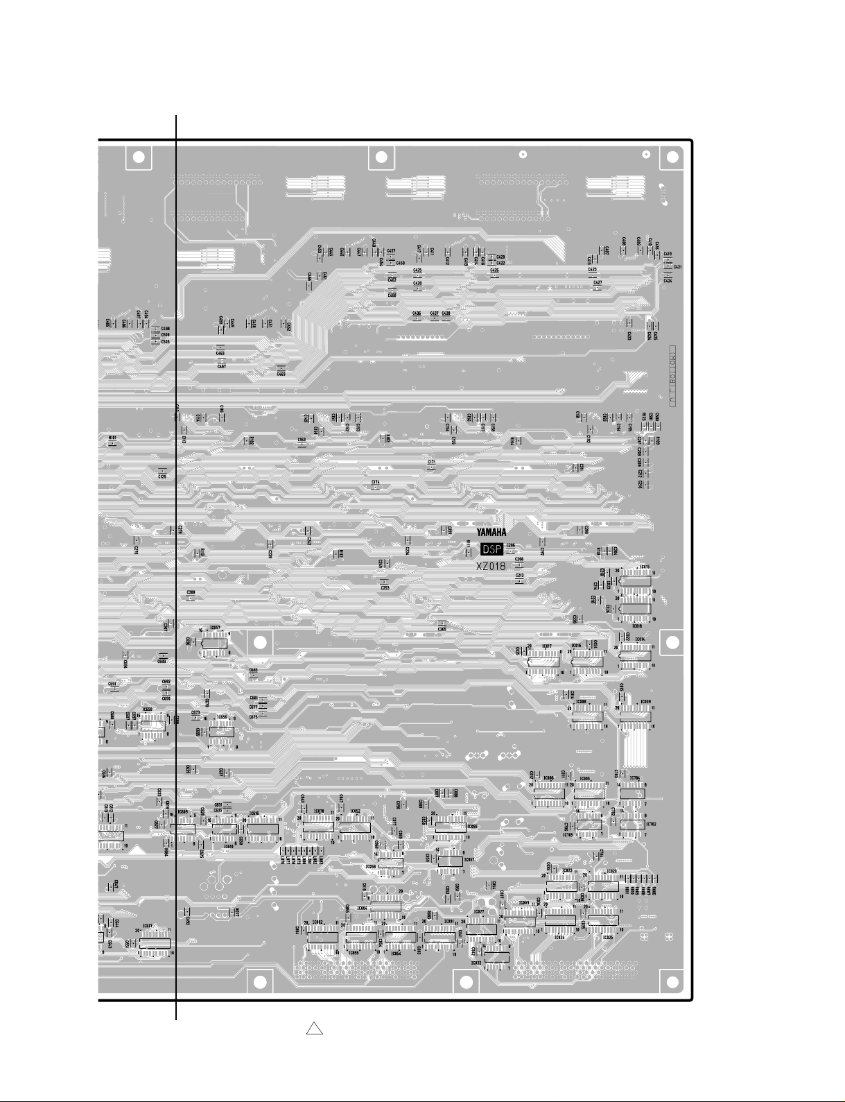
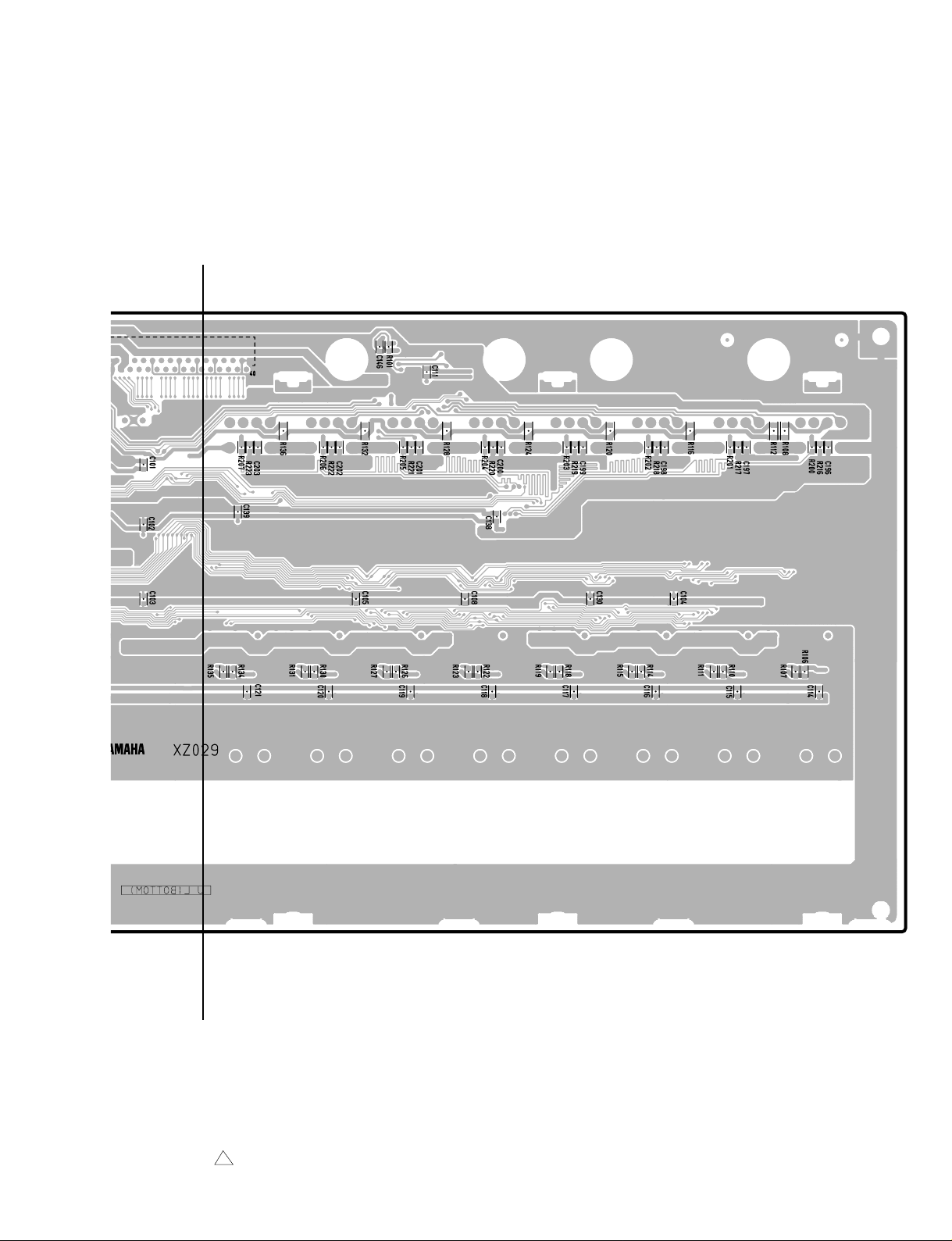
DM2000
F
3NA-V628520-3 1
F'
Pattern side
101
Page 2
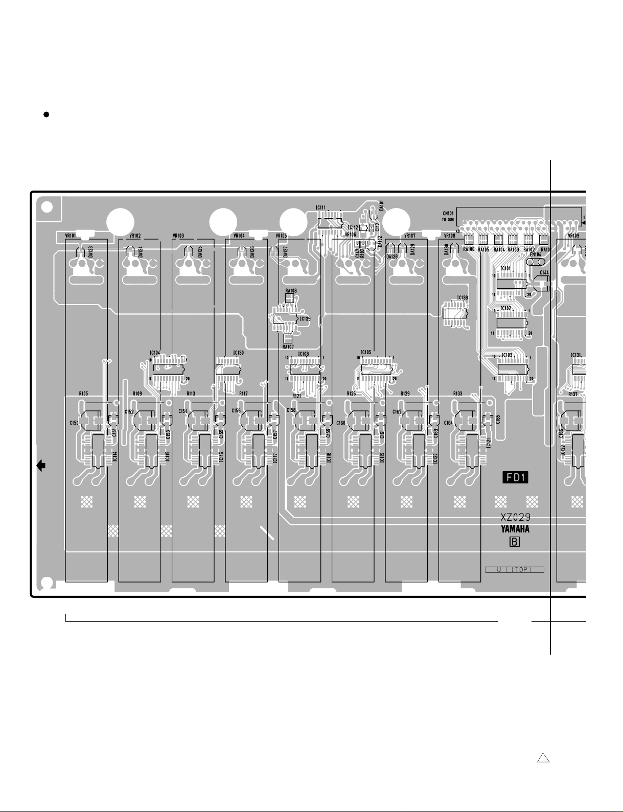
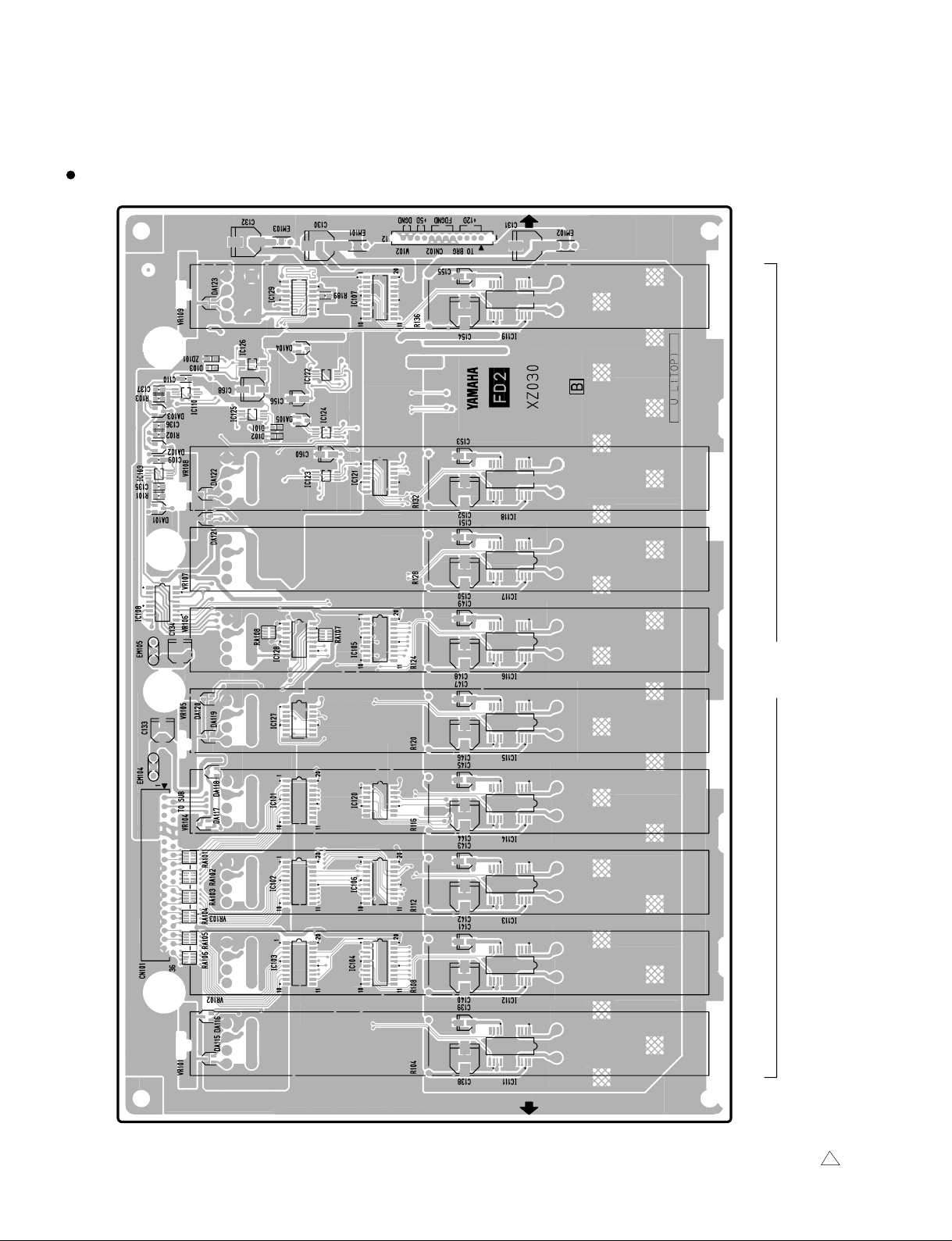
DM2000
FD1 Circuit Board
G
to SUB-CN118
102
12345678
FADER
3NA-V628660-2 1
9
G'
Page 3
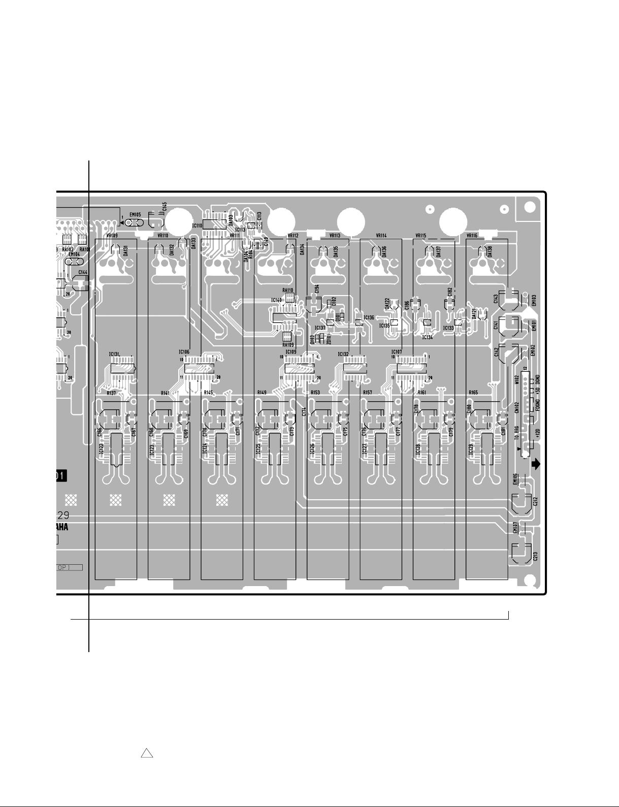
N118
DM2000
G
ER
to BRG
-CN022
9 10111213141516
Component side
G'
3NA-V628660-2 1
103
Page 4
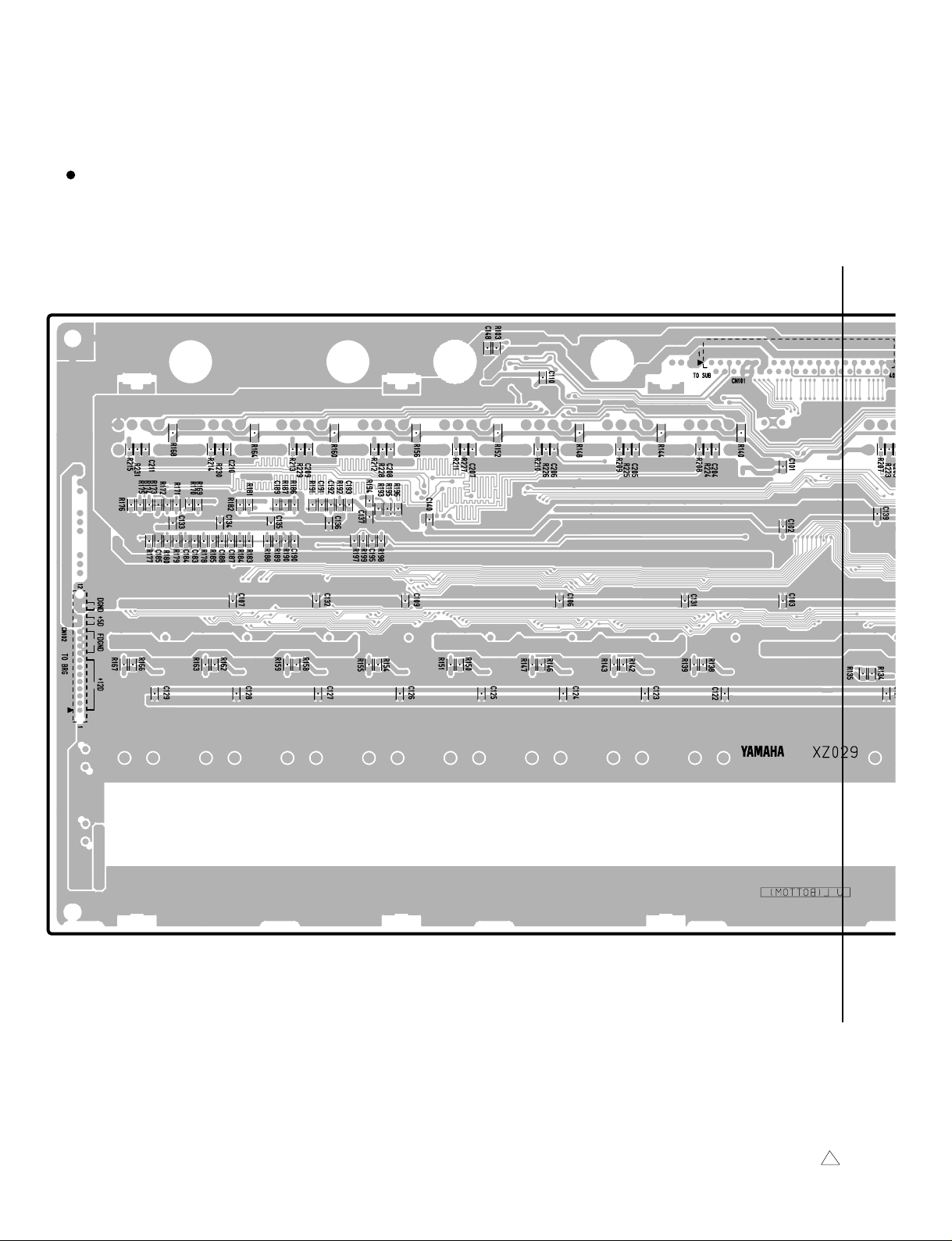
DM2000
FD1 Circuit Board
H
104
H'
3NA-V628660-3 1
Page 5
DM2000
H
H'
3NA-V628660-3 1
Pattern side
105
Page 6
DM2000
to SUB-CN119
to BRG
-CN023
17 18 19 20 21 22 23 24 STEREO
FADER
FD2 Circuit Board
106
Component side
3NA-V628680-2 1
Page 7
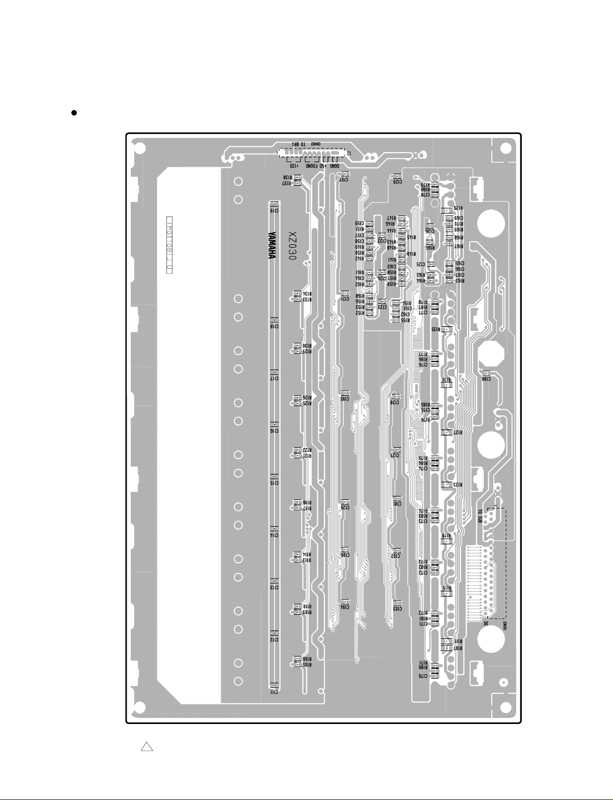
FD2 Circuit Board
DM2000
3NA-V628680-3 1
Pattern side
107
Page 8

DM2000
5
JK1 Circuit Board
I
2TR IN DIGITAL 2TR OUT DIGITAL
1
AES/EBU
2
AES/EBU
3
COAXIAL
1
AES/EBU
2
AES/EBU
3
COAXIAL
IN
7
108
to DSP-CN902 to DSP-CN901
I'
3NA-V628590-2 1
Page 9
I
WORD CLOCK TO HOST TIME CODE INPUT
IN
75Ω
1 OUT 2
SERIAL USB MTC SMPTE KEYBOARD
DM2000
I'
3NA-V628590-2 1
to BRG-CN014
Component side
109
Page 10
DM2000
JK1 Circuit Board
J
110
J'
3NA-V628590-2 1
Page 11
DM2000
J
J'
3NA-V628590-2 1
Pattern side
111
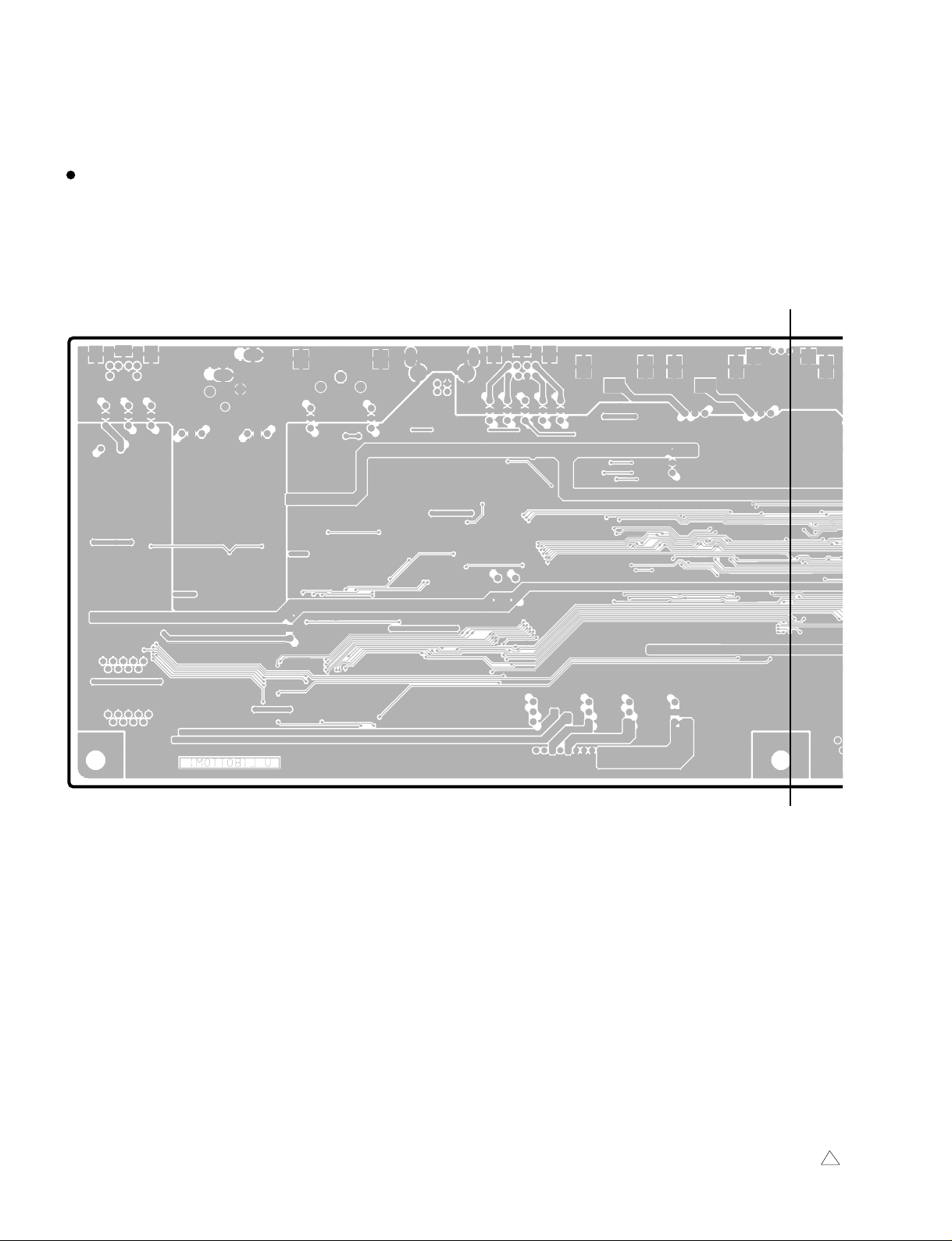
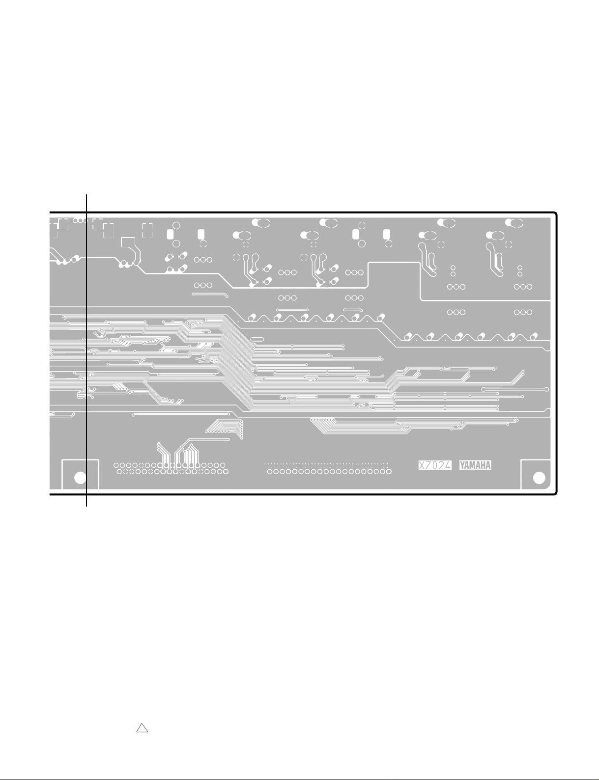
Page 12

DM2000
JK2 Circuit Board
to BRG-CN015
K
to DSP-CN903
METER
(from MB2000)
CONTROL
REMOTE
THRU OUT
MIDI
K'
L
112
3NA-V628620-2
3NA-V628620-3
L'
Page 13
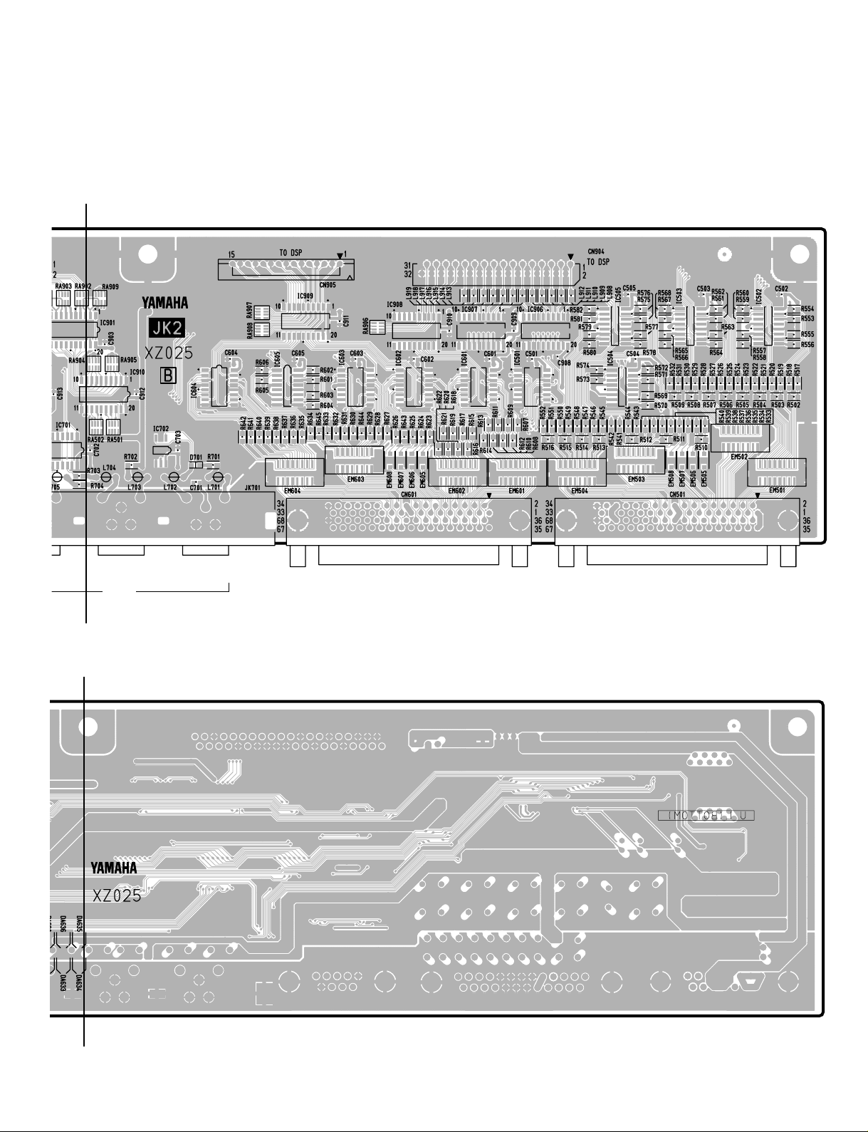
DM2000
K
to DSP-CN905 to DSP-CN904
K'
L
OUT
MIDI
IN
CASCADE OUT CASCADE IN
Component side
L'
3NA-V628620-2
Pattern side
3NA-V628620-3
113
Page 14
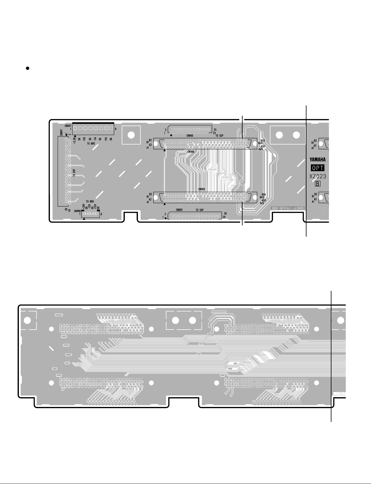
DM2000
OPTCircuit Board
M
to DSP
-CN807
to BRG-CN016
to BRG-CN017 to DSP-CN803
to DSP-CN806
SLOT6
SLOT3
M'
N
114
N'
3NA-V628580-2
Page 15
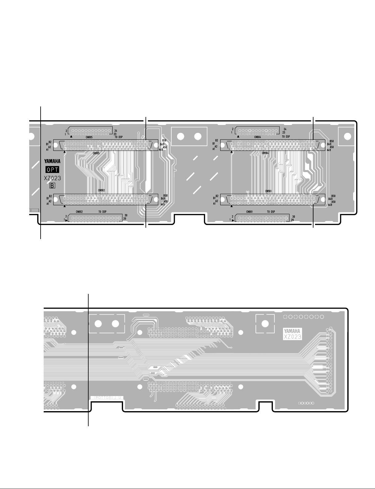
DM2000
M
M'
to DSP-CN805 to DSP-CN804
to DSP-CN802
SLOT5 SLOT4
SLOT2
to DSP-CN801
N
SLOT1
Component side
3NA-V628580-2
N'
Pattern side
115
Page 16
DM2000
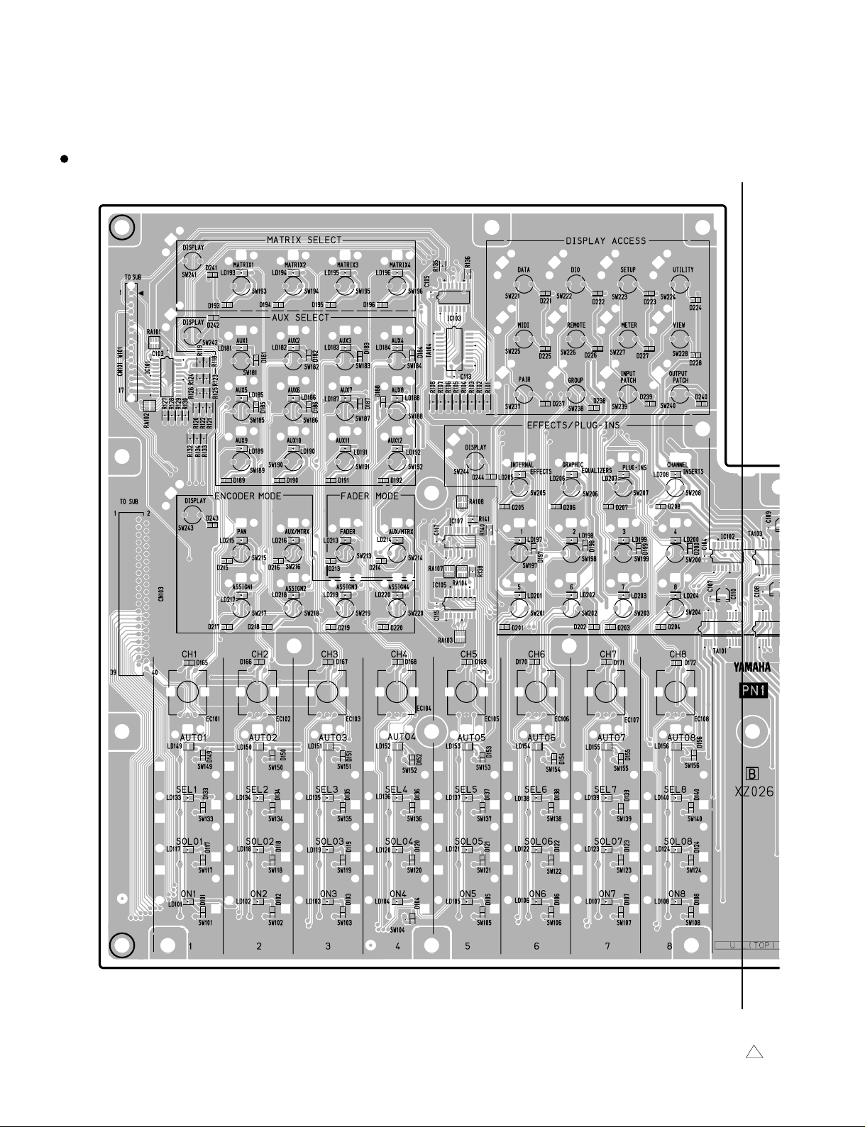
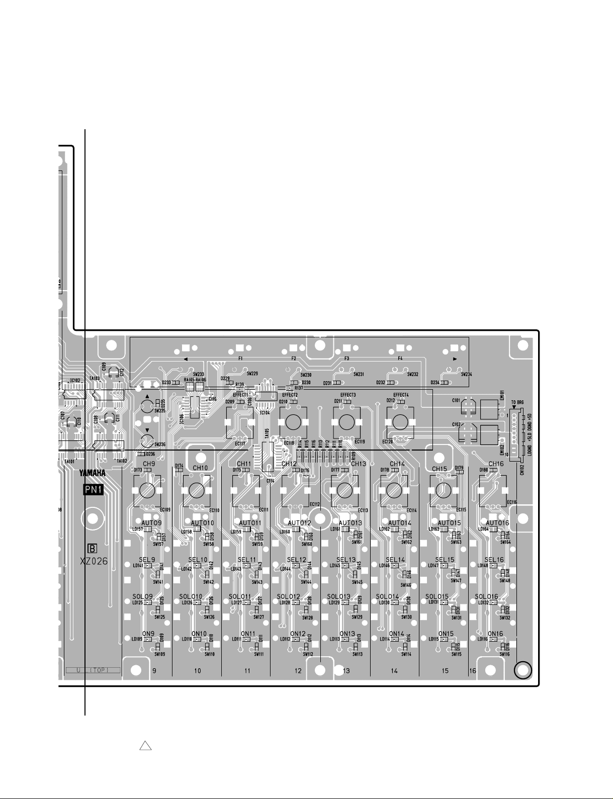
PN1 Circuit Board
to SUB
-CN115
O
to SUB
-CN111
116
O'
3NA-V628630-2 1
Page 17
DM2000
O
Component side
to BRG
-CN019
O'
3NA-V628630-2 1
117
Page 18
DM2000
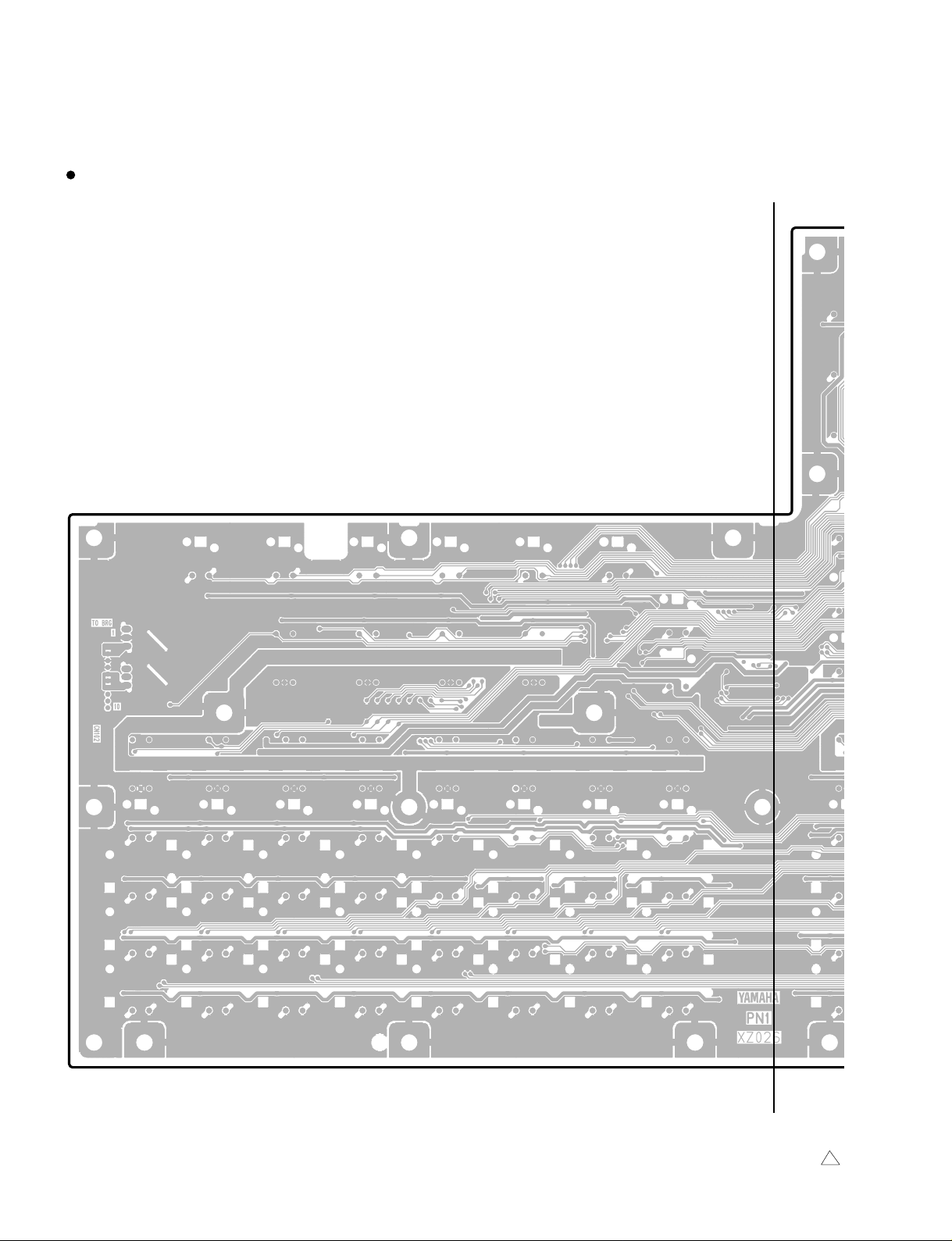
PN1 Circuit Board
P
118
P'
3NA-V628630-2 1
Page 19

DM2000
P
P'
3NA-V628630-2 1
Pattern side
119
Page 20
DM2000
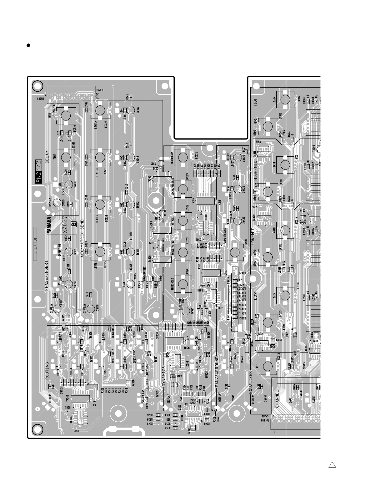
N
PN2 (1/2) Circuit Board
to PN3-CN501
Q
120
to SUB-C
Q'
3NA-V628640-2 1
Page 21

DM2000
Q
to BRG-CN020
PN2 (2/2) Circuit Board
JOY STICK
to PN3
-CN504
Component side
Component side
to SUB-CN112to SUB-CN113
Q'
3NA-V628640-2 1
121
Page 22

DM2000
PN2 (1/2) Circuit Board
R
PN2 (2/2) Circuit Board
Pattern side
122
R'
3NA-V628640-2 1
Page 23

DM2000
R
R'
3NA-V628640-2 1
Pattern side
123
Page 24
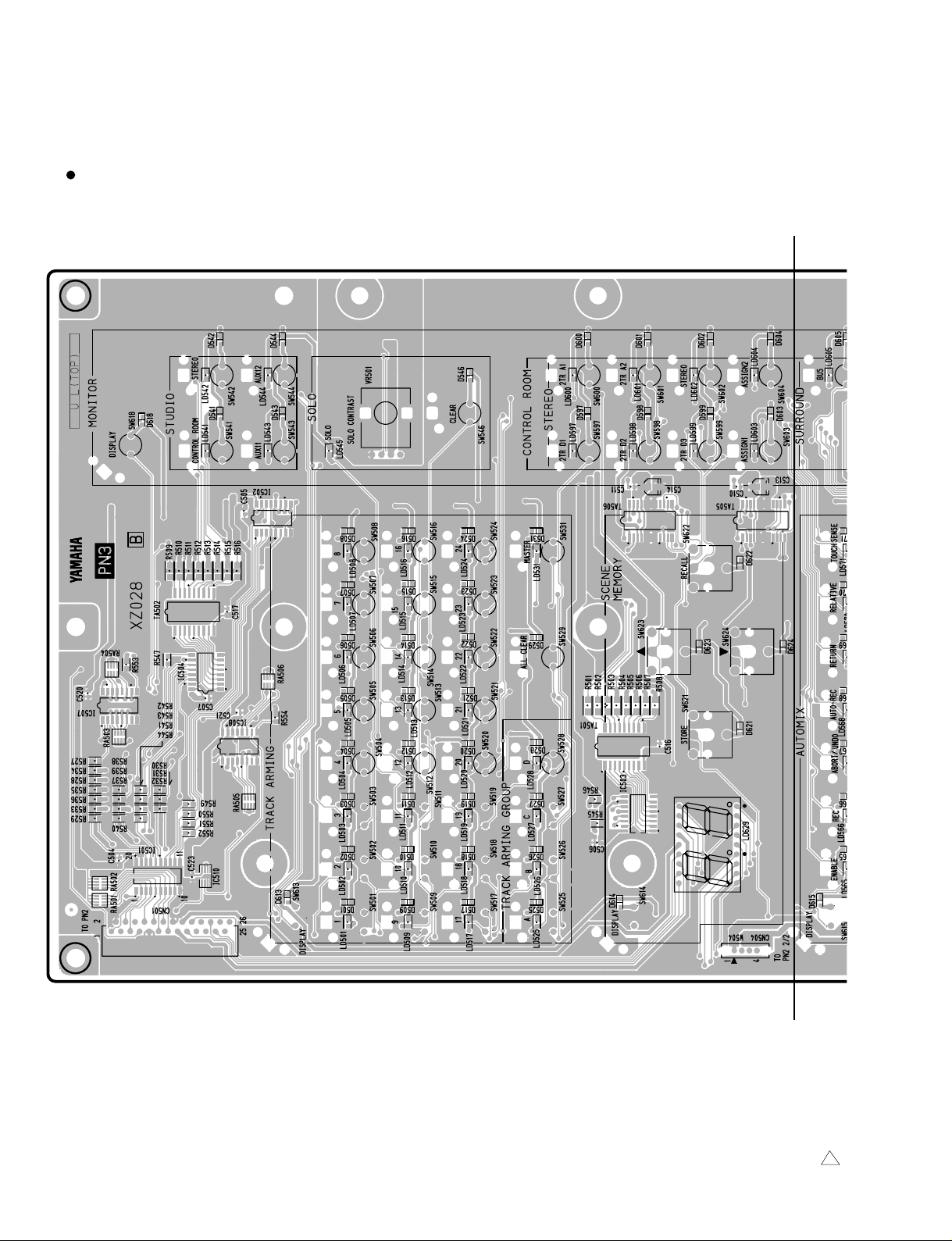
DM2000
PN3 Circuit Board
S
124
to PN2 (1/2)-CN303 to PN2 (2/2)-CN305
S'
3NA-V628650-2 1
Page 25
DM2000
S
to DA2-CN100
to BRG
-CN021
to PN4 (1/2)
-CN701
N305 to SUB-CN114
S'
3NA-V628650-2 1
Component side
125
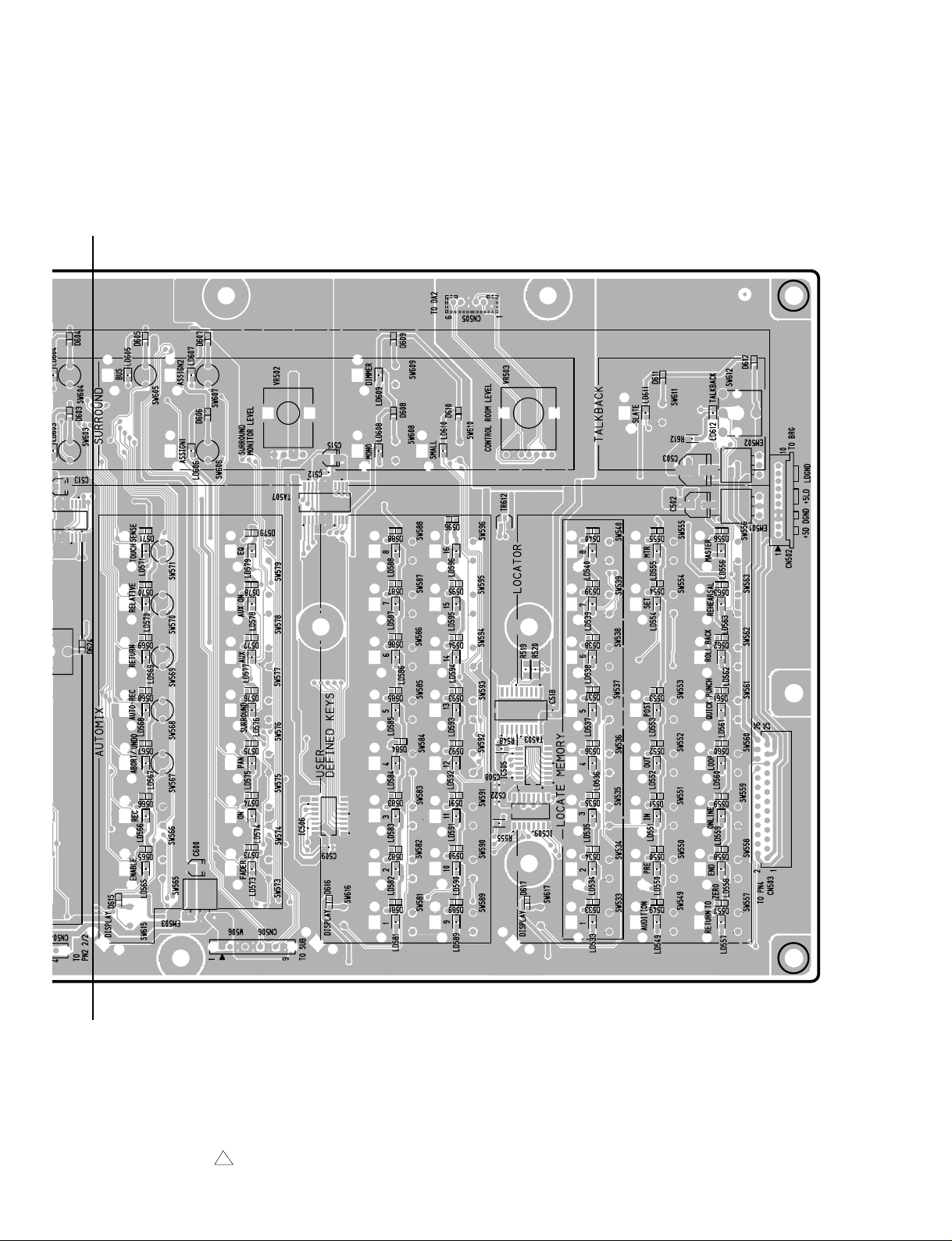
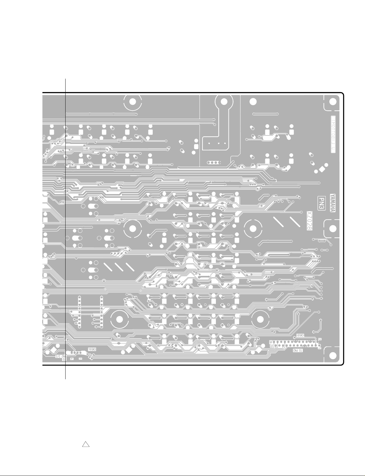
Page 26

DM2000
PN3 Circuit Board
T
126
T'
3NA-V628650-2 1
Page 27
DM2000
T
T'
3NA-V628650-2 1
Pattern side
127
Page 28
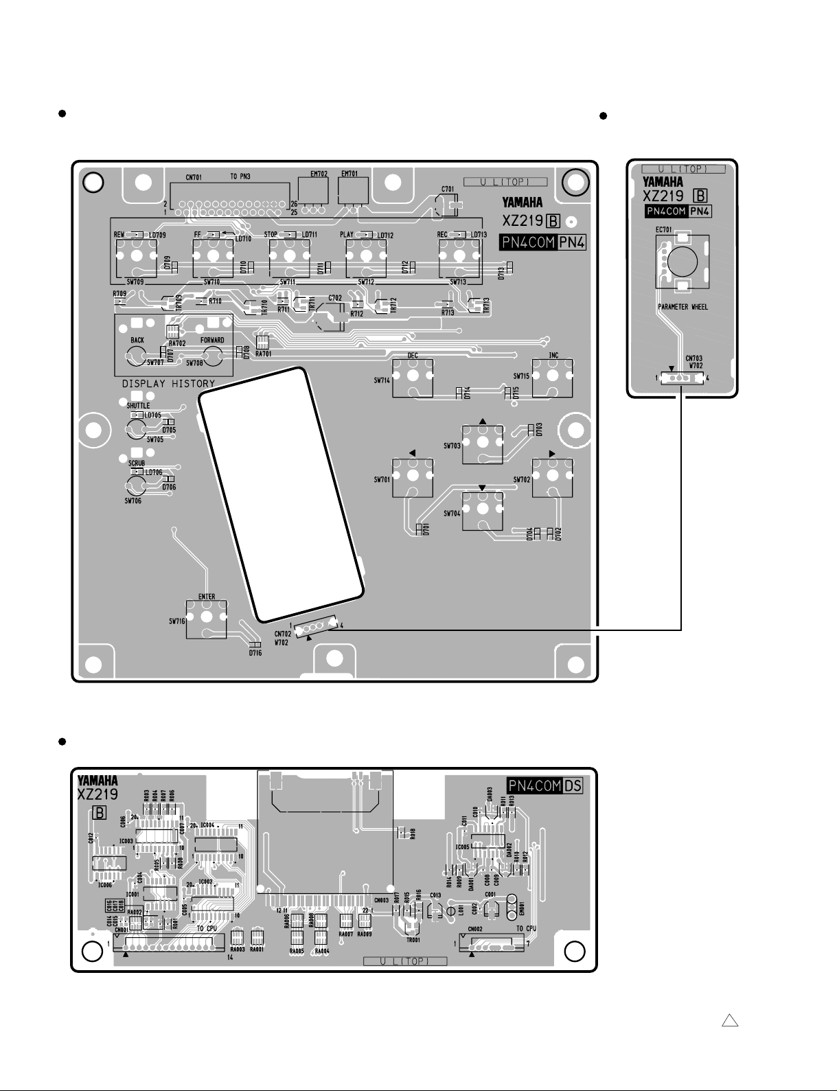
DM2000
PN4COM (PN4 (1/2)) Circuit Board
to PN3-CN503
PN4COM (PN4 (2/2))
Circuit Board
PN4COM (DS) Circuit Board
to CPU-CN108 to CPU-CN107SMART MEDIA
128
Component side
Component side
3NA-V830050-2 1
Page 29

DM2000
PN4COM (PN4 (1/2)) Circuit Board
PN4COM (PN4 (2/2))
Circuit Board
PN4COM (DS) Circuit Board
3NA-V830050-2 1
Pattern side
Pattern side
129
Page 30
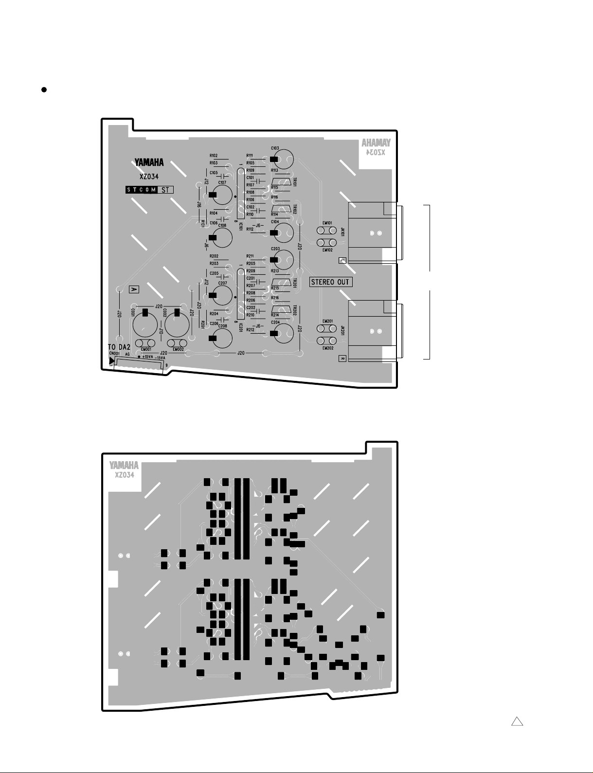
DM2000
STCOM (ST) Circuit Board
L
STEREO OUT
to DA2-CN301
R
Component side
130
Pattern side
3NA-V628800-1 1
Page 31

STCOM (STD) Circuit Board
STUDIO LEVEL
DM2000
L
STUDIO MONITOR OUT
R
to DA2-CN501
Component side
STEREO OUT
L/R
3NA-V628800-1 1
Pattern side
131
Page 32
DM2000
SUB Circuit Board
U
to PN2 (1/2)
-CN304
to PN3
-CN506
to PN2 (1/2)
-CN301
to BRG-CN024 to FD2-CN101 to FD1-CN101
132
U'
3NA-V628530-2
Page 33

DM2000
U
to PN1
-CN101
to FL Module (Master)
-CN2
to PN1
-CN103
not used
(for debug
SUB1 (IC101))
to CPU
-CN101
not used
(for check)
U'
3NA-V628530-2
Component side
133
Page 34

DM2000
SUB Circuit Board
V
134
V'
3NA-V628530-2
Page 35

DM2000
V
V'
3NA-V628530-2
Pattern side
135
Page 36
DM2000
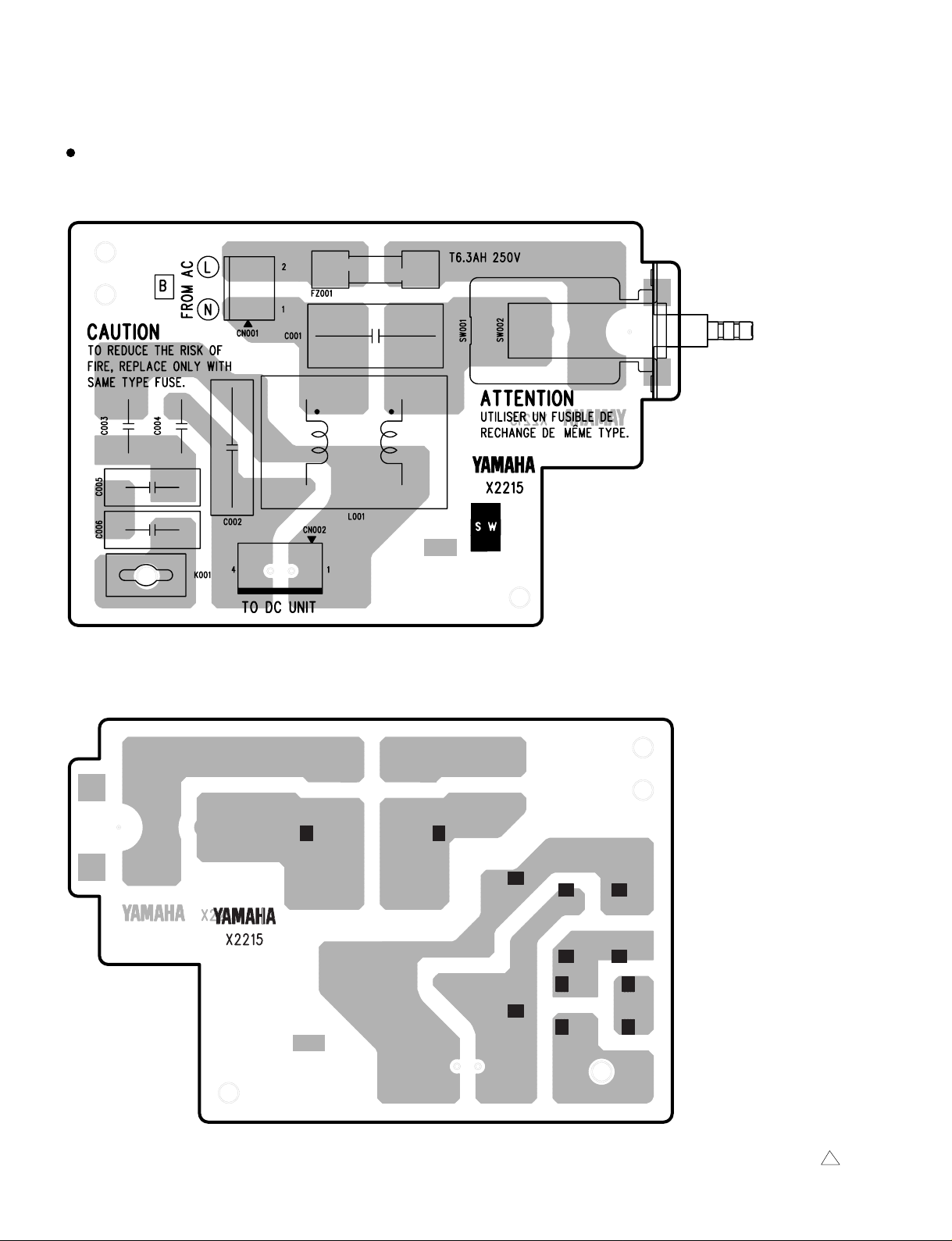
SW Circuit Board
to AC IN
POWER ON/OFF
to Power Supply Unit-CN1
Component side
136
Pattern side
3NA-V654390-2 4
Page 37

to LAMP1
DC Circuit Board
to PN1-CN102
DM2000
W
W
W'
to PN2-CN201
to LAMP2
to METER
(DM2000)
W'
3NA-V628880-2 2
Component side
137
Page 38

DM2000
PNCOM (PN1) Circuit Board
X
X'
Y
138
Y'
3NA-V773550-2 2
Page 39

DM2000
X
to DC-CN302
X'
to PN2-CN203
Component side
Y
Y'
3NA-V773550-2 2
Pattern side
139
Page 40

DM2000
PNCOM (PN2) Circuit Board
Z
to DC-CN303
to PN1-CN101
Z'
a
140
3NA-V773550-2 2
a'
Page 41

DM2000
Z
Z'
a
Component side
a'
3NA-V773550-2 2
Pattern side
141
Page 42

DM2000
INSPECTIONS
Perform the Check of DM2000.
1. Preparation
1-1. Condition
Conditioned as follows unless specified:
WORD CLOCK to be INT 96kHz.
Only CH to be checked shall be turned ON.
PAN: Center
GAIN: MIN
PAD: ON
INSERT: OFF
FADER: NORMAL (0dB)
0dBu = 0.775Vrms
0dBV = 1Vrms = 2.2dBu
0dBFS = 0 decibel full scale
Output impedance of oscillator shall be 150Ω.
Input impedance of oscilloscope, level gauge shall
be over 100kΩ.
Noise measuring shall be at 12.7kHz, and be
corrected with LPF of –6dB/OCT.
(Not average value but effective value should be
measured.)
Distortion measurement should be performed at
80kHz and corrected with LPF of –6dB/OCT.
When checking analogue output, the following
conditions shall be added or changed:
When measuring maximum output, unless
specified, output 0dB from the built-in oscillator.
The load of analogue output shall be as follows:
INSERTOUT: 10kΩ
STEREO OUT (XLR): 600Ω
STEREO OUT (PIN): 10kΩ
CONTROL ROOM MONIT OR OUT LARGE: 600Ω
CONTROL ROOM MONITOR OUT SMALL: 600Ω
STUDIO MONITOR OUT: 10kΩ
OMNI OUT: 10kΩ
PHONES: 8Ω
1-2. Initialization
Turn the power supply switch ON while pressing
the [STORE] key to start and initialize the system
in accordance with the instruction on the screen.
Important data should be backed up by MIDI dump
or Smart Media. (See page.187)
1-3. Main program writing
If the program version is not latest, program of the
latest version must be installed.
q How to check the program version.
T urning ON the power while pressing the [UTILITY]
key will display the version number.
w Procedure of version up
a.Prepare Smart Media (3.3V, Capacity:
8MB~128MB) and copy the program to be written
into the root directory.
b.Insert the Smart Media into the MEMORY CARD
SLOT while power OFF.
142
c.When powered ON, the count down 5-1 will be
displayed on the LCD and the flash memory will
be erased and the program writing executed.
d. When the writing completes, the system will be
automatically restarted.
For the latest main program, please download from the
YSISS home page and store into the Smart Media.
2. Check of ANALOGUE IN/OUT at WORD
CLOCK INT 96 kHz
2-1. STEREO OUT L/R (XLR)
Condition: Input from the [INSERT IN] terminal of
CH1.
Turn ON the [INSERT] switch.
q Gain (L/R common)
Input Frequency Input Level Specified Output Level Permissible range
1kHz +4dBu +4dBu +4±2dBu
w f Characteristic (L/R common)
Condition: Permissible range of 1kHz to be standard.
Input Frequency Input Level Permissible range
20Hz +4dBu -1.5~ +0.5dB
40kHz +4dBu -1.5~ +0.5dB
e Distortion factor (L/R common)
Input Frequency Output Level Permissible range
1kHz +16dBu 0.01% or below
r Residual noise (L/R common)
Condition: [STEREO OUT] key to be s witched OFF.
Permissible range
-92dBu or below
t Level gap between L/R
Level gap measured in q to be decided as follows:
Permissible range
Within 1dB
y Cross talk between L and R
Condition: PAN to fully lean to the L side.
Input Frequency
1kHz +16dBu -64dBu or below
Confirm that the R side also satisfies the above
conditions.
u Maximum output (L/R common)
Input Frequency Output Level Permissible range
1kHz +18dBu +18±0.5dBu 0.01% or below
Condition: Connect hot, cold terminal to GND
Input Frequency Output Level Permissible range
1kHz +18dBu +18±1.0dBu 0.02% or below
Output Level (L)
respectively.
Permissible range (R)
Permissible range
(Distortion factor)
Permissible range
(Distortion factor)
Page 43

DM2000
2-2. STEREO OUT L/R (PIN)
Condition: Input from the [INSERT IN] terminal of
CH1.
The [INSERT] switch to be set to ON.
q Gain (L/R common)
Input Frequency Input Level Specified output level Permissible range
1kHz +4dBu -10dBV -10±2dBV
w Characteristic (L/R common)
Condition:
Input Frequency Input Level Permissible range
Permissible range of 1kHz to be standard.
20Hz +4dBu -1.5~ +0.5dB
40kHz +4dBu -1.5~ +0.5dB
e Maximum output (L/R common)
Input Frequency Output Level Permissible range
1kHz +4dBV +4±0.5dBV 0.02% or below
Permissible range
(Distortion factor)
r Cross talk between L and R
Condition: PAN to fully lean to the L side.
Input Frequency
1kHz +2dBV -78dBu or below
Output Level (L)
Permissible range (R)
Confirm that the R side also satisfies the above
conditions.
2-3. CONTROL ROOM MONITOR OUT LARGE L/R
CONTROL ROOM MONITOR OUT SMALL L/R
Condition: Input from the [INSERT IN] terminal of
CH1.
The [INSERT] switch to be set to ON.
Set the [CONTROL ROOM MONIT OR
LEVEL] control to MAX.
Set the [SMALL TRIM] control to MAX.
Set the [STEREO] key of CONTROL
ROOM to ON.
Set the [SMALL] switch to OFF for
LARGE measurement and ON for
SMALL.
q Gain (L/R common for LARGE/SMALL)
Input Frequency Input Level Specified output level Permissible range
1kHz +4dBu +4dBu +4±2dBu
w f Characteristic (L/R common for LARGE/SMALL)
Condition:
Input Frequency Input Level Permissible range
Permissible range of 1kHz to be standard.
20Hz +4dBu -1.5~ +0.5dB
40kHz +4dBu -1.5~ +0.5dB
e Distortion factor (L/R common for LARGE/SMALL)
Input Frequency Output Level Permissible range
1kHz +16dBu 0.02% or below
r Residual noise (L/R common for LARGE/SMALL)
Condition: [STEREO OUT] key to be s witched OFF.
CONTROL ROOM MONITOR LEVEL Permissible range
MAX -92dBu or below
MIN -98dBu or below
(L/R common for only SMALL)
Condition: [STEREO OUT] key to be s witched OFF.
CONTROL ROOM MONITOR LEVEL Permissible range
MAX -92dBu or below
MIN
-100dBu or below
t Level gap between L/R (LARGE/SMALL common)
Level gap measured in q to be decided as follows:
Permissible range
Within 1dB
y Cross talk between L and R (LARGE/SMALL
common)
Condition: PAN to fully lean to the L side.
Input Frequency
1kHz +16dBu -64dBu or below
Output Level (L)
Permissible range (R)
Confirm that the R side also satisfies the above
conditions.
u Maximum output (L/R common for LARGE/SMALL)
Input Frequency Output Level Permissible range
1kHz +18dBu +18±0.5dBu 0.02% or below
Permissible range
(Distortion factor)
Condition: Connect hot, cold terminal to GND
respectively.
Input Frequency Output Level Permissible range
1kHz +18dBu +18±1.0dBu 0.02% or below
Permissible range
(Distortion factor)
2-4. STUDIO MONITOR OUT L/R
Condition: Input from the [INSERT IN] terminal of
CH1.
The [INSERT] switch to be set to ON.
The [MONITOR OUT LEVEL] control
to be set to MAX.
The [STEREO] key of STUDIO to be
turned ON.
q Gain (L/R common)
Input Frequency Input Level Specified output level Permissible range
1kHz +4dBu +4dBu +4±2dBu
w f Characteristic (L/R common)
Condition:
Input Frequency Input Level Permissible range
Permissible range of 1kHz to be standard.
20Hz +4dBu -1.5~ +0.5dB
40kHz +4dBu -1.5~ +0.5dB
e Distortion factor (L/R common)
Input Frequency Output Level Permissible range
1kHz +16dBu 0.02% or below
143
Page 44
DM2000
r Residual noise (L/R common)
Condition: [STEREO OUT] key to be s witched OFF.
MONITOR OUT LEVEL Permissible range
MAX -92dBu or below
MIN
-100dBu or below
t Level gap between L/R
Level gap measured in q to be decided as f ollows:
Permissible range
Within 1dB
y Cross talk between L and R
Condition: PAN to fully lean to the L side.
Input Frequency
1kHz +16dBu -64dBu or below
Output Level (L)
Permissible range (R)
Confirm that the R side also satisfies the above
conditions.
u Maximum output (L/R common)
Input Frequency Output Level Permissible range
1kHz +18dBu +18±0.5dBu 0.02% or below
Permissible range
(Distortion factor)
Condition: Connect hot, cold terminal to GND
respectively.
Input Frequency Output Level Permissible range
1kHz +18dBu +18±1.0dBu 0.02% or below
Permissible range
(Distortion factor)
2-5. OMNI OUT 1~8
Condition: Input from the [INSERT IN] terminal of
CH1.
Turn ON the [INSERT] switch.
T urn ON BUS1~8 at ROUTING of CH1.
Assign BUS nCH to OMNI nCH with
the [OUTPUT PATCH] key.
T urn ON MASTER F ADER of BUS 1~8.
The slide switches SW101~801
(8 switches) in DA1 circuit board are to
be +18dB.
q Gain (OMNI OUT 1~8)
Input Frequency Input Level Specified Output Level Permissible range
1kHz +4dBu +4dBu +4±2dBu
w f Characteristic (OMNI OUT 1~8)
Condition:
Input Frequency Input Level Permissible range
Permissible range of 1kHz to be standard.
20Hz +4dBu -1.5~ +0.5dB
40kHz +4dBu -1.5~ +0.5dB
t Level gap among the terminals [OMNI OUT 1~8]
Level gap measured in q and w to be decided as
follows:
Permissible range
Within 1dB
y Cross talk between odd CH/even CH
Input Frequency Output Level (odd CH) Permissible range (even CH)
1kHz +16dBu -64dBu or below
Confirm that the even side also satisfies the above
conditions.
u Maximum output (OMNI OUT 1~8)
Input Frequency Output Level Permissible range
1kHz +18dBu +18±0.5dBu 0.02% or below
Permissible range
(Distortion factor)
Condition: Connect hot, cold terminal to GND
respectively.
Input Frequency Output Level Permissible range
1kHz +18dBu +18±1.0dBu 0.02% or below
Permissible range
(Distortion factor)
2-6. Output Level Gap
Condition: [STERO OUT L/R] terminal
[CONTROL ROOM MONITOR OUT
LARGE L/R] terminal
[CONTROL ROOM MONITOR OUT
SMALL L/R] terminal
[STUDIO MONITOR OUT L/R] terminal
[OMNI OUT 1~8] terminal (SW101~
801(8 switches) in DA1 circuit board are
of at +18dB.)
The range of the gain gaps measured
at 1kHz for these terminals is specified
as follows:
Permissible range
Within 2dB
2-7. PHONES OUT L/R
Condition: Input from the [INSERT IN] terminal of
CH1.
The [INSERT] switch to be set to ON.
The [PHONES LEVEL] control to be set
to MAX.
q Gain (L/R common)
Input Frequency Input Level Specified output level Permissible range
1kHz +4dBu -12.8dBu -12.8±2dBu
144
e Distortion factor (OMNI OUT 1~8)
Input Frequency Output Level Permissible range
1kHz +16dBu 0.02% or below
r Residual noise (OMNI OUT 1~8)
Condition: [BUS OUT] key to be switched OFF.
Permissible range
-92dBu or below
w f Characteristic (L/R common)
Condition:
Input Frequency Input Level Permissible range
Permissible range of 1kHz to be standard.
20Hz +4dBu -3~0.5dB
40kHz +4dBu -3~0.5dB
Page 45

DM2000
e Distortion factor (L/R common)
Input Frequency Output Level Permissible range
1kHz -10dBu 0.04% or below
r Residual noise (L/R common)
Condition: The [PHONE LEVEL] control to be set
to MIN.
Permissible range
-100dBu or below
t Level gap between L/R
Level gap measured in q to be decided as follows:
Permissible range
Within 1dB
y Maximum output (L/R common)
Condition: To output –6dB from the built-in
oscillator.
Input Frequency Output Level Permissible range
1kHz -4.8dBu -4.8±0.5dBu 0.04% or below
Permissible range
(Distortion factor)
u Cross talk between L and R
Condition: PAN to fully lean to the L side.
Input Frequency
1kHz -10dBu -75dBu or below
Output Level (L)
Permissible range (R)
Confirm that the R side also satisfies the above
conditions.
2-8. 2TR IN ANALOG 1 L/R
Condition:
Check at the [STEREO OUT L] terminal (XLR).
q Gain (L/R common)
Input Frequency Input Level Specified output level Permissible range
1kHz +4dBu +4dBu +4±2dBu
y Cross talk between L and R
Condition: Input the signal into the L side.
The R side to be shorted at 150Ω.
Input Frequency
1kHz +16dBu -64dBu or below
Output Level (L)
Permissible range (R)
Confirm that the R side also satisfies the above
conditions.
2-9. 2TR IN ANALOG 2 L/R
Condition:
Check at the [STEREO OUT L] terminal (XLR).
q Gain (L/R common)
Input Frequency Input Level Specified output level Permissible range
1kHz -10dBV +4dBu +4±2dBu
w f Characteristic (L/R common)
Condition:
Input Frequency Input Level Permissible range
Permissible range of 1kHz to be standard.
20Hz -10dBV -1.5~0.5dB
40kHz -10dBV -1.5~0.5dB
e Distortion factor (L/R common)
Input Frequency Output Level Permissible range
1kHz +16dBu 0.02% or below
r Residual noise (L/R common)
Condition: [2TR IN ANALOG 2] terminal to be
shorted at 150Ω.
Permissible range
-86dBu or below
t Level gap between L/R
Level gap measured in q to be decided as follows:
Permissible range
Within 1dB
w f Characteristic (L/R common)
Condition:
Input Frequency Input Level Permissible range
Permissible range of 1kHz to be standard.
20Hz +4dBu -1.5~0.5dB
40kHz +4dBu -1.5~0.5dB
e Distortion factor (L/R common)
Input Frequency Output Level Permissible range
1kHz +16dBu 0.02% or below
r Residual noise (L/R common)
Condition: [2TR IN ANALOG 1] terminal to be
shorted at 150Ω.
Permissible range
-86dBu or below
t Level gap between L/R
Level gap measured in q to be decided as follows:
Permissible range
Within 1dB
y Cross talk between L and R
Condition: Input the signal into the L side.
The R side to be shorted at 150Ω.
Input Frequency
1kHz +16dBu -64dBu or below
Output Level (L)
Permissible range (R)
Confirm that the R side also satisfies the above
conditions.
2-10.
CH IN 1~24 (XLR, PHONE)
Condition:
Check at the [STEREO OUT L] terminal (XLR).
Turn OFF the [INSERT] switch.
A. GAIN MAX, PAD OFF
q Gain (CH1~24)
Input Frequency Input Level Specified output level Permissible range
1kHz -60dBu +4dBu +4±2dBu
145
Page 46

DM2000
w f Characteristic (CH1~24)
Condition:
Input Frequency Input Level Permissible range
Permissible range of 1kHz to be standard.
20Hz -60dBu -1.5~0.5dB
40kHz -60dBu -1.5~0.5dB
e Distortion factor (CH1~24)
Input Frequency Output Level Permissible range
1kHz +16dBu 0.02% or below
r Noise level EIN(CH1~24)
Condition: Measured CH IN to be shorted at 150Ω.
Permissible range
-64dBu or below
Howev er , if not be within the abo v e range , confirm
that the measured value is (Gain at 1kHz)
<
=
-128.
t Level gap (CH1~24)
Level gap measured in q to be decided as f ollows:
Permissible range
Within 2dB
B. GAIN MIN, PAD ON
q Gain (CH1~24)
Input Frequency Input Level Specified output level Permissible range
1kHz +10dBu +4dBu +4±2dBu
w Distortion factor (CH1~24)
Input Frequency Output Level Permissible range
1kHz +16dBu 0.01% or below
e Noise level (CH1~24)
Condition: Measured CH IN to be shorted at 150Ω.
Permissible range
-86dBu or below
Light OFF
LED level Input frequency Input level
PEAK 1kHz +19dBu +13dBu
SIGNAL 1kHz -12dBu -18dBu
Reference output level
(INSERT OUT)
C. Phantom (CH1~24)
Voltage with XLR Pin 2 and Pin3 shorted, a load
of 10kΩ between Pin 2 and 1, and the Phantom
Switch ON is prescribed as follows:
Permissible range
DC 31~37V
Check if a discharge of electricity occurs quickly
when the Phantom switch is turned OFF.
2-11.
TALKBACK
Condition: Check at the [STEREO OUT L/R]
terminal (XLR).
Set the [TALKBACK LEVEL] control to
MAX.
T urn ON the [SLATE] key of TALKBACK.
Confirm the signal through the
microphone.
3. ANALOGU IN/OUT check at 48kHz WORD
CLOCK INT
3-1. STEREO OUT L/R (XLR)
Condition: Input from the [INSERT IN] terminal of
CH1.
Turn ON the [INSERT] switch.
q Gain (L/R common)
Input Frequency Input Level Specified output level Permissible range
1kHz +4dBu +4dBu +4±2dBu
r INSERT OUT gain (CH1~24)
Input Frequency Input Level Specified output level Permissible range
1kHz +10dBu +4dBu +4±1.5dBu
t INSERT OUT noise level (CH1~24)
Condition: Measured CH IN to be shorted at 150Ω.
Permissible range
-90dBu or below
y Checking the action of the Level Meter (CH1~24)
Condition: Input the specified levels into the CH
to be measured.
Concurrent inputs into CH 1~24 are
possible.
Confirm visually each LED ON/OFF of
PEAK, NOMINAL, SIGNAL.
Light ON
LED level Input frequency Input level
PEAK 1kHz +23dBu +17dBu
SIGNAL 1kHz -8dBu -14dBu
Reference output level
(INSERT OUT)
146
w f Characteristic (L/R common)
Condition:
Input Frequency Input Level Permissible range
Permissible range of 1kHz to be standard.
20Hz +4dBu -1.5~ +0.5dB
20kHz +4dBu -1.5~ +0.5dB
e Distortion factor (L/R common)
Input Frequency Output Level Permissible range
1kHz +16dBu 0.01% or below
r Residual noise (L/R common)
Condition: Turn OFF the [STEREO OUT] key.
Permissible range
-92dBU or below
3-2. CONTROL ROOM MONITOR OUT LARGE L/R
Condition: Input from the [INSERT IN] terminal of
CH1.
Turn ON the [INSERT] switch.
Set the [CONTROL ROOM MONIT OR
LEVEL] control to MAX.
Page 47

DM2000
Turn ON the [STEREO] key of
CONTROL ROOM.
q Gain (LARGE L/R common)
Input Frequency Input Level Specified output level Permissible range
1kHz +4dBu +4dBu +4±2dBu
w f Characteristic (LARGE L/R common)
Condition:
Input Frequency Input Level Permissible range
Permissible range of 1kHz to be standard.
20Hz +4dBu -1.5~ +0.5dB
20kHz +4dBu -1.5~ +0.5dB
e Distortion factor (LARGE L/R common)
Input Frequency Output Level Permissible range
1kHz +16dBu 0.02% or below
r Residual noise (LARGE L/R common)
Condition: Set the [STEREO OUT] key to OFF.
CONTROL ROOM MONITOR OUT LEVEL Permissible range
MAX -92dBu or below
3-3. STUDIO MONITOR OUT L/R
Condition: Input from the [INSERT IN] terminal of
CH1.
Turn ON the [INSERT] switch.
Set the [MONITOR OUT LEVEL]
control to MAX.
T urn ON the [STEREO] key of STUDIO .
q Gain (L/R common)
Input Frequency Input Level Specified output level Permissible range
1kHz +4dBu +4dBu +4±2dBu
w f Characteristic (L/R common)
Condition:
Input Frequency Input Level Permissible range
Permissible range of 1kHz to be standard.
20Hz +4dBu -1.5~ +0.5dB
20kHz +4dBu -1.5~ +0.5dB
e Distortion factor (L/R common)
Input Frequency Output Level Permissible range
1kHz +16dBu 0.02% or below
r Residual noise (L/R common)
Condition: Set the [STEREO OUT] key to OFF.
MONITOR OUT LEVEL Permissible range
MAX -92dBu or below
3-4. OMNI OUT 1~8
Condition: Input from the [INSERT IN] terminal of
CH1.
Switch ON the [INSERT] switch.
T urn ON BUS1~8 at R OUTING of CH1.
Assign BUS nCH to OMNI nCH with
the [OUTPUT PATCH] key.
T urn ON MASTER F ADER of BUS 1~8.
The slide switches SW101~801
(8 switches) in DA1 circuit board are
to be +18dB.
q Gain (OMNI OUT 1~8)
Input Frequency Input Level Specified Output Level Permissible range
1kHz +4dBu +4dBu +4±2dBu
w f Characteristic (OMNI OUT 1~8)
Condition:
Input Frequency Input Level Permissible range
Permissible range of 1kHz to be standard.
20Hz +4dBu -1.5~ +0.5dB
20kHz +4dBu -1.5~ +0.5dB
e Distortion factor (OMNI OUT 1~8)
Input Frequency Output Level Permissible range
1kHz +16dBu 0.02% or below
r Residual noise (OMNI OUT 1~8)
Condition: [BUS OUT] key to be switched OFF.
Permissible range
-92dBU or below
3-5. PHONES OUT L/R
Condition: Input from the [INSERT IN] terminal of
CH1.
Turn ON the [INSERT] switch.
Set the [PHONES LEVEL] control to
MAX.
q Gain (L/R common)
Input Frequency Input Level Specified output level Permissible range
1kHz +4dBu -12.8dBu -12.8±2dBu
w f Characteristic (L/R common)
Condition:
Input Frequency Input Level Permissible range
Permissible range of 1kHz to be standard.
20Hz +4dBu -3~0.5dB
20kHz +4dBu -3~0.5dB
e Distortion factor (L/R common)
Input Frequency Output Level Permissible range
1kHz -10dBu 0.04% or below
r Residual noise (L/R common)
Condition: Set the [PHONES LEVEL] control to MIN.
Permissible range
-100dBu or below
3-6. 2TR IN ANALOG 1 L/R
Condition:
Check at the [STEREO OUT L] terminal (XLR).
q Gain (L/R common)
Input Frequency Input Level Specified output level Permissible range
1kHz +4dBu +4dBu +4±2dBu
147
Page 48

DM2000
w f Characteristic (L/R common)
Condition:
Input Frequency Input Level Permissible range
Permissible range of 1kHz to be standard.
20Hz +4dBu -1.5~0.5dB
20kHz +4dBu -1.5~0.5dB
e Distortion factor (L/R common)
Input Frequency Output Level Permissible range
1kHz +16dBu 0.02% or below
r Residual noise (L/R common)
Condition: [2TR IN ANALOG 1] terminal to be
shorted at 150Ω.
Permissible range
-88dBu or below
3-7. 2TR IN ANALOG 2 L/R
Condition:
Check at the [STEREO OUT L] terminal (XLR).
q Gain (L/R common)
Input Frequency Input Level Specified output level Permissible range
1kHz -10dBV +4dBu +4±2dBu
w f Characteristic (L/R common)
Condition:
Input Frequency Input Level Permissible range
Permissible range of 1kHz to be standard.
20Hz -10dBV -1.5~0.5dB
20kHz -10dBV -1.5~0.5dB
e Distortion factor (L/R common)
Input Frequency Output Level Permissible range
1kHz +16dBu 0.02% or below
r Residual noise (L/R common)
Condition: [2TR IN ANALOG 2] terminal to be
shorted at 150Ω.
Permissible range
-88dBu or below
3-8. CH IN 1~24 (XLR, PHONE)
Condition:
Check at the [STEREO OUT L] terminal (XLR).
Turn OFF the [INSERT] switch.
Set the [GAIN] control to MIN and the
[PAD] switch to ON.
q Gain (CH1~24)
Input Frequency Input Level Specified output level Permissible range
1kHz +10dBu +4dBu +4±2dBu
w f Characteristic (CH1~24)
Condition:
Input Frequency Input Level Permissible range
Permissible range of 1kHz to be standard.
20Hz +10dBu -1.5~0.5dB
20kHz +10dBu -1.5~0.5dB
e Distortion factor (CH1~24)
Input Frequency Output Level Permissible range
1kHz +16dBu 0.01% or below
r Noise level (CH1~24)
Condition: Measured CH IN to be shorted at 150Ω.
Permissible range
-88dBu or below
4. Checking DIGITAL IN/OUT
4-1. 2TR DIGITAL OUT 1,2,3
Condition: Use System Two.
Input from the [INSERT IN] terminal of
CH1.
Turn ON the [INSERT] switch.
A. WORD CLOCK INT 48kHz.
Condition: Set WORD CLOCK INT to 48kHz.
Turn OFF SRC of the [2TR DIGITAL
OUT] terminal.
q Gain (2TR DIGITAL OUT 1,2,3 common)
Input Frequency Input Level Specified output level Permissible range
1kHz +4dBu -14dBFS -14±2dBFS
w f Characteristic (2TR DIGITAL OUT 1)
Condition:
Input Frequency Input Level Permissible range
e Distortion factor (2TR DIGITAL OUT 1)
Input Frequency Output Level Permissible range
B. WORD CLOCK INT 96kHz.
Condition: Set WORD CLOCK INT to 96kHz.
q Gain (2TR DIGITAL OUT 1,2,3 common)
Input Frequency Input Level Specified output level Permissible range
1kHz +4dBu -14dBFS -14±2dBFS
w f Characteristic (2TR DIGITAL OUT 1)
Condition:
Input Frequency Input Level Permissible range
e Distortion factor (2TR DIGITAL OUT 1)
Input Frequency Output Level Permissible range
Permissible range of 1kHz to be standard.
20Hz +4dBu -1.0~0.5dB
20kHz +4dBu -1.0~0.5dB
1kHz -2dBFS 0.02% or below
Turn OFF SRC of the [2TR DIGITAL
OUT] terminal.
Permissible range of 1kHz to be standard.
20Hz +4dBu -1.0~0.5dB
40kHz +4dBu -1.5~0.5dB
1kHz -2dBFS 0.02% or below
148
Page 49

DM2000
C. SRC action
Condition: Set WORD CLOCK INT to 96kHz.
Turn ON SRC of CH to be measured.
q FS (2TR DIGITAL OUT 1,2,3 common)
Input Frequency Input Level Specified output level Permissible range
1kHz -2dBFS 44.1kHz 44.1kHz±100Hz
w Distortion factor (2TR DIGIT AL OUT 1,2,3 common)
Input Frequency Output Level Permissible range
1kHz -2dBFS 0.005% or below
4-2. 2TR DIGITAL IN 1,2,3
Condition: Use System Two.
Check at the [STEREO OUT L/R]
terminal (XLR).
Select as follows for WORD CLOCK.
When checking the [2TR DIGITAL
IN 1] terminal: 2TR D1
When checking the [2TR DIGITAL
IN 2] terminal: 2TR D2
When checking the [2TR DIGITAL
IN 3] terminal: 2TR D3
A. 48kHz.
Condition: Set the frequency setting (Sample
Rate) of System Two to 48kHz.
Turn OFF SRC of the [2TR DIGITAL
IN] terminal.
q Gain (2TR DIGITAL IN 1,2,3 common)
Input Frequency Input Level Specified output level Permissible range
1kHz -14dBFS +4dBu +4±2dBu
w f Characteristic (2TR DIGITAL IN 1)
Condition:
Input Frequency Input Level Permissible range
Permissible range of 1kHz to be standard.
20Hz -14dBFS -1.0~0.5dB
20kHz -14dBFS -1.0~0.5dB
e Distortion factor (2TR DIGITAL IN 1)
Input Frequency Output Level Permissible range
1kHz +16dBu 0.02% or below
w f Characteristic (2TR DIGITAL IN 1)
Condition:
Input Frequency Input Level Permissible range
Permissible range of 1kHz to be standard.
20Hz -14dBFS -1.0~0.5dB
40kHz -14dBFS -1.5~0.5dB
e Distortion factor (2TR DIGITAL IN 1)
Input Frequency Output Level Permissible range
1kHz +16dBu 0.02% or below
C. SRC action
Condition: Set WORD CLOCK INT to 96kHz.
Check at the [2TR DIGITAL OUT1]
terminal.
Set the frequency setting of System
Two (Sample Rate) to 44.1kHz.
Turn ON SRC of CH to be measured.
q FS (2TR DIGITAL IN 1,2,3 common)
Input Frequency Input Level Specified output level Permissible range
1kHz -14dBFS 96kHz 96kHz±100Hz
w Distortion factor (2TR DIGITAL IN 1,2,3 common)
Input Frequency Output Level Permissible range
1kHz -14dBFS 0.005% or below
4-3. PLL action range of WORD CLOCK IN and 2TR
DIGITAL IN 1,2,3
Condition: Use System Two.
Check at the [STEREO OUT L/R]
terminal (XLR).
Select as follows for WORD CLOCK.
When checking the [WORD CLOCK
IN] terminal: WC IN
When checking the [2TR DIGITAL
IN 1] terminal: 2TR D1
When checking the [2TR DIGITAL
IN 2] terminal: 2TR D2
When checking the [2TR DIGITAL
IN 3] terminal: 2TR D3
Input from the [INSERT IN] terminal of
CH1.
Turn ON the [INSERT] switch.
B. 96kHz.
Condition: Set the frequency setting (Sample
Rate) of System Two to 96kHz.
Turn OFF SRC of the [2TR DIGITAL
IN] terminal.
q Gain (2TR DIGITAL IN 1,2,3 common)
Input Frequency Input Level Specified output level Permissible range
1kHz -14dBFS +4dBu +4±2dBu
A. 96kHz + 6% (101.76kHz)
Condition: When checking the [WORD CLOCK IN]
terminal, set the frequency setting of
the oscillator to 96kHz + 6%. When
checking the [2TR DIGITAL IN 1,2,3]
terminal, set the setting of System Two
(Sample Rage) to 96kHz + 6%.
q Distortion factor (WORD CLOCK IN, 2TR DIGITAL
IN 1,2,3 common)
Input Frequency Output Level Permissible range
1kHz +16dBu 0.02% or below
149
Page 50

DM2000
B. 44.1kHz - 10% (39.69kHz)
Condition: When checking the [WORD CLOCK IN]
terminal, set the frequency setting of
the oscillator to 44.1kHz - 10%. When
checking the [2TR DIGITAL IN 1,2,3]
terminal, set the setting of System Two
(Sample Rage) to 44.1kHz - 10%.
q Distortion factor (WORD CLOCK IN, 2TR DIGITAL
IN 1,2,3 common)
Input Frequency Output Level Permissible range
1kHz +16dBu 0.02% or below
5. Measuring jitter
Condition: Use System Two.
Select Sec, PK
BW: Select 700Hz~100kHz.
Check at the [2TR DIGITAL OUT1]
terminal.
5-1. WORD CLOCK INT
Condition: For WORD CLOCK, select as follows:
q Jitter
WORD CLOCK Permissible range
INT 44.1kHz 5nsec. or below
INT 48kHz 5nsec. or below
INT 88.2kHz 5nsec. or below
INT 96kHz 5nsec. or below
5-2. WORD CLOCK EXT
Condition: Select as follows for WORD CLOCK.
When checking the [WORD CLOCK
IN] terminal: WC IN
When checking the [2TR DIGITAL
IN 1] terminal: 2TR D1
When checking the [2TR DIGITAL
IN 2] terminal: 2TR D2
When checking the [2TR DIGITAL
IN 3] terminal: 2TR D3
When checking the [WORD CLOCK IN]
terminal, select the values in the
following table f or the frequency setting
of the oscillator.
When checking the [2TR DIGITAL IN
1,2,3] terminals, select the values in the
following table f or the frequency setting
of the System Two (Sample Rate).
q Jitter (WORD CLOCK IN, 2TR DIGITAL IN 1,2,3
common)
WORD CLOCK Permissible range
44.1kHz 10nsec. or below
48kHz 10nsec. or below
88.2kHz 10nsec. or below
96kHz 10nsec. or below
6. Sound check
Check the following items with the sense of hearing.
EFT 1~8
Check at No.13 and 19 of EFFECT LIBRARY.
ANALOG INPUT, ANALOG OUTPUT
Check at the [STEREO OUT L/R] terminal (XLR)
of CH1, CH12, CH24.
2TR DIGITAL IN 1,2,3
Condition: Set WORD CLOCK INT to 96kHz.
Check at the [STEREO OUT L/R]
terminal (XLR).
Set the frequency setting of System
Two (Sample Rate) to 44.1kHz.
Turn ON SRC of CH to be measured.
150
Page 51

DM2000
151
Page 52

DM2000
152
Page 53

DM2000
153
Page 54

DM2000
154
Page 55

DM2000
155
Page 56

DM2000
156
Page 57

DM2000
157
Page 58

DM2000
158
Page 59

SERVICE CHECK PROGRAM
1-1
1-2
1-3
1-4
1-5
1-6
1-7
1-8
1-9
1-10
1-11
1-12
1-13
1-14
1-15
1-16
1-17
1-18
1-19
1-25
1-26
1-27
1-28
1-29
1-30
1-31
1-32
1-33
1-36
1-37
MCS(FPGA)
BATT
RTC
DSP6,SIO
DSP7,SIO,ATSC2
MIDI
2TR IN/OUT(DIO)
WORD CLOCK
CASCADE
SMART Media
TIME Code
LCD
PANEL LED
PANEL ALL LED
PANEL SW
FADER TSense
FADER Move
ENCODER(CH)
ENCODER(etc.)
FL
METER LED
METER SW
Check the FPGA register by Read/Write.
Check the voltage of the backup battery.
Initiate, set, or display the Real Time Clock.
Check the SIO connection by Reading/Writing the register of each DSP6.
Check the SIO and ATSC2 connection by Reading/Writing the register of each DSP7.
MIDI OUT-->Check the Send/Receive of IN.
Check by Loop Backing the 2TR IN/OUT DIGITAL.
Count the Fs of WCLK OUT at WCLK IN to judge the LOCK of PLL.
Check the Send/Receive of CASCADE OUT > IN.
Check the control panel, Check the Smart Media by Read/Write.
Check the MTC MIDI input.
Display the entire screen in black and white to check contrast volume
.
LEDs (including 7 Seg LEDs) will light sequentially as specified.
Check all LEDs for gradual brightness and for each color.
Press the SW sequentially as specified for check.
Check the touch sense sensitivity of the FADER.
Check the moving time and stop position of the FADER.
Rotate the Encoder (CH1-24) for check.
Rotate the Encoder (etc.) for check.
Turn ON/OFF all symbols of FL and display characters.
MB2000 LEDs (including 7 Seg LEDs) will light sequentially as specified.
Pressing the SW of MB2000 will turn ON/OFF corresponding LED.
Auto
Auto
Semi-Auto
Auto
Auto
Auto
Auto
Semi-Auto
Auto
Semi-Auto
Auto
Visual check
Visual check
Visual check
Semi-Auto
Semi-Auto
Semi-Auto
Semi-Auto
Semi-Auto
Visual check
Visual check
Visual check
Item Check name Outline of check item
Judge
Execute the service check programs for DM2000 and MB2000.
DM2000
0. Outline
0-1 How to operate
Keys used for the service check on the panel
[DEC] key: used to Exit or
Cancel check
[↑][↓][←][→]key:
used to select check item
and select OK/NG
[ENTER] key: used to decide selection or EXIT
0-2. Explanation of screen
(Fig.1)
Example of screen for the entire check items
--- DM2000 test --- (C)YAMAHA 2001
F/W Ver. MAIN Vx.xx METER Vx.xx
SUB1 Vx.xx SUB2 Vx.xx
1
OK
MCS(FPGA) Reg.
2
OK
BATT
3
OK
RTC
4
OK
DSP6,SIO
5
OK
DSP7,SIO,ATSC2
7
OK
MIDI
13
OK
2TR IN/OUT(DIO)
14
OK
WORD CLOCK
16
OK
CASCADE
17
OK
SMART Media
18
OK
TIME Code
OK 25
OK 26
NG 27
OK 28
OK 29
OK 30
OK 31
OK 32
OK 33
OK 36
OK 37
LCD
PANEL LED
PANEL ALL LED
PANEL SW
FADER TSense
FADER Move
ENCODER(CH)
ENCODER(etc.)
FL
METER LED
METER SW
Version number of each CPU ROM
Each check result
Selected item is displayed in reverse.
How to select:
Use the [↑], [↓], [←], or [→] key in the
lower right of the panel to select items.
After this, pressing the [ENTER] key will
call each individual check screen.
(Fig.3)
Example B of individual check screen (when checking each one
of multiple items automatically (semi-automatically) or visually)
--- METER LED ---
OK 1 Channel Bargraph
NG 2 Stereo Bargraph
OK 3 Time Code
OK 4 Others
OK NG
EXIT ([DEC Key]->[ENTER Key])
1) When starting the check, OK/NG selection items will be
displayed. Judging by actions and results, select OK/NG.
Use the [←] or [→] key for the selection and decide by
using the [ENTER] key.
2) Choice of OK or NG displays the next check item
automatically.
3) Pressing the [DBC] key while the entry of OK/NG decision
is being waited will reverse the appearance of [EXIT] and
this screen is terminated when the [ENTER] key is pressed.
(Some check items can be processed the [EXIT] by
pressing the [DEC] key even during the execution.)
If executed the [EXIT] before all the check items are
completed, the judges of Fig.1 will be displayed as NG.
4) Check items with numbers at the head as such Fig.3 are
selectable. Select an item using the [↑] or [↓] key and press
the [ENTER] key to start a check. For the ones without
numbers at the head the check will be automatically initiated.
0-3 List of check items
36 and 37 are the test programs of MB2000.
(Fig.2)
Example A of individual check screen
(when forwarding check items by automatic judge)
OK INSert line
OK BUSY line
OK PROTECT line
NG Media W/R
NG:W->R[Addr=01:W34:R3F]
EXIT ([DEC Key]->[ENTER Key])
1) Check is carried out automatically and turns to the [EXIT]
--- SMART Media ---
mode when all items are completed. Pressing the [ENTER]
key will display the screen of Fig.1.
2) If redo the check, return to Fig.1 to select items.
Check is executed from the
upper sequentially.
Item being checked is
displayed in reverse.
Display area of indicative
message
Display area of NG message
A long message will be
displayed over two lines.
(Scroll up)
Checked items and item numbers correspond to those of the
test program.
159
Page 60

DM2000
1. Service Check
Common contents
1) The contents and example screens of execution for
each check item are displayed.
Common preparation
1) Objectives to be checked: DM2000 + MB2000
2) Cable: MIDI cable: 2
CANNON cable: 2
COAXIAL cable: 1
BNC cable: 1
D-SUB 68pin (CASCADE) cable: 1
3) Others SMART Media: 2 (3.3 V, one is attached
to the PROTECT seal)
4) How to During normal operation, pressing the
start
DM2000
[SEL] key in the order CH [6 7 1 1] and
pressing the [ENTER] key will display
the dialogue box for appro val. After this ,
selecting YES and pressing the
[ENTER] key will restart the DM2000
in the Service Check mode.
Connection diagram of Service Check
DM2000
2TR OUT D1
2TR OUT D2
2TR OUT D3
WCLK OUT 1
WCLK OUT 2
TO HOST-SERIAL
SLOT1
SLOT2
SLOT3
SLOT4
SLOT5
SLOT6
TO HOST-USB
TIME CODE-MTC
TIME CODE-SMPTE
KEYBOARD
CASCADE
CASCADE
2TR IN D1
2TR IN D2
2TR IN D3
WCLK IN
IN
OUT
MIDI IN
OUT
THRU
REMOTE
CONTROL
METER
(Replace OUT1 with
OUT2 in the middle of
the procedure.)
MB2000
1-1 MCS(FPGA) Test
Contents: Read/Write the Reg. (00, 0f, 10, 11, 15, 16)
of FPGA to compare and judge and then
readout the Reg.12 (Ver) and display it.
Example of execution screen
--- MCS(FPGA) ---
NG Adrs,Data BUS
OK Ver.Check
Version: 0212
NG: MCS Wxx:12 --> Rxx:FF
EXIT ([DEC Key]->[ENTER Key])
Reg.12 (Ver) is
displayed
Displayed when NG.
For the Ver.Check test, select OK when “Version: 0212” is
displayed.
1-2 BATT Test
Contents: Measure the voltage of the backup battery
in A/D for automatic judge.
Example of execution screen
--- BATT ---
OK BATT
NG:BATT (2.56V)
EXIT ([DEC Key]->[ENTER Key])
Certified voltage range
2.80V~3.50V
Below 0.5V is NG:
BATT NONE
1-3 RTC Test
Contents: Initiate, set, and display the Real Time Cloc k.
Example of execution screen
--- RTC ---
-- 1 Init RTC
-- 2 Set Date Time
OK 3 Display Date Time
01/07/04 WEDNESDAY 12:00:00
parameter error
SET Year/Month/Day WeekName Hour:Min:Sec
EXIT ([DEC Key]->[ENTER Key])
Display Date Time
is displayed.
Displayed for wrong
entry for Set Date
time.
Confirm the current date and time displayed are correct by
executing “3 Display Date Time.”
If not correct, enter correct date and time at “2 Set Date Time”
and confirm again the date and time at “3 Display Date Time.”
In case of abnormal Real Time Clock mov ement or when the
backup battery of the CPU circuit board, initialize Real Time
Clock at “1 Init RTC” and perform the above setting.
160
Page 61

DM2000
1) When selecting “2 Set Date Time”
Selected item will be displayed inversely.
Move to an item to be changed using the [←] or [→] key.
Change values using the [↑] or [↓] key and press the
[ENTER] key to decide.
The [DEC] key cancels the setting. Day of the week is
automatically entered.
yy /mm/dd hh:mm:ss
01 /07/04 12:34:56
1-4 DSP6, S10 Test
1-5 DSP7, S10, ATSC2 test
Contents: Check DataBUS and AddressBUS for good
or bad by Writing/Reading the Register of
each DSP6 and DSP7.
Compare and check by Writing/Reading
DRAM and SDRAM of each DSP6 and DSP7
through the Register.
Check the SIO connection between each
DSP, and between ATSC by sending/
receiving signal.
Example of execution screen
--- DSP6 ---
OK DSP6,SIO
1: CPU Interface (Data bus)
NG: TxBusy
--- DSP7 ---
OK DSP7,SIO,ATSC2
Items are not selectable
since all items are auto
matically selected.
During execution,
displayed one after
another from “1:”.
Details when NG are displayed.
Too many NGs will stop the
display within about 20.
Explanation about expression when DSP6 and DSP7 are
common, or when NG:
1) CPU Interface (Data Bus)
0000 0000 XXXX 0000 0000 0000 0000 X00X
MSB X=Error bit LSB
2) SIO Connection (DSP7 -> DSP6)
NG: 1 IC111(1)[Soxx] -> IC401(1)[Sixx]
...
NG: IC401(1)
...
IC number
DSP number
(#1..#nn)
1-7 MIDI Test
Contents: Sending/Receiving the string
“SCI2:TEST¥n”(¥n=0Ah) at 31.25Kbps from/
into MIDI OUT→MIDI IN, verify if identical.
Preparation: Connect MIDI OUT and MIDI IN connector
of the unit.
Example of execution screen
--- MIDI Loopback ---
OK MIDI Check
OK: SCI2
EXIT ([DEC Key]->[ENTER Key])
1-13 2TR IN/OUT (DIO) Test
Contents: Connect 2TR OUT DIGITAL 1,2,3 to 2TR IN
DIGITAL 1,2,3 and verify by using DSP SIO.
Check the SRC function of 2TR OUT DIGITAL
1,2,3 by using 2TR IN DIGITAL 1,2,3.
Preparation: Connect each MIDI OUT DIGITAL 1,2,3 and
each MIDI IN DIGITAL 1,2,3 connector of
the unit respectively.
1: CPU Interface (Data bus)
NG: BIF #01 0000 XXXX 0000
EXIT ([DEC Key]->[ENTER Key])
...
Test item for DSP6 Test item for DSP7
1: CPU Interface (Data bus) 1: CPU Interface (Data Bus)
2: CPU Interface (Data bus) 2: CPU Interface (Chip Select)
3:
CPU Interface (Chip Select, TXB)
CPU Interface (Address bus)
4:
CPU Interface (BUS W/R Reg.)
5:
6:
DRAM Interface (Data Bus)
7:
DRAM Interface (Address Bus)
8:
DRAM Interface (Address Bus & MPR)
9: SIO Connection 9:
(DSP6--->DSP6 SIO test) A:
3: CPU Interface (Address Bus)
4: E-RAM Interface (Data Bus)
5:
E-RAM Interface (Address Bus)
6:
SIO Connection (DSP7 -> DSP6)
7:
SIO Connection (DSP6 -> DSP7)
8:
SIO Connection (DSP7 -> DSP7)
SIO Connection (ATSC -> DSP7)
SIO Connection (DSP7 -> ATSC)
A: PIO Connection
(DSP6--->DSP6 SIO test)
Example of execution screen
--- 2TR IN/OUT ---
OK
FS,SRC ON/OFF
OK OUT-->IN
OK DIR Lock(RERR)
OK DIT,DIR CDIN,CDOUT
NG: DIO IC114-SO62-->IC651-->IC902
-->IC903-->IC604-->IC101-SI30
EXIT ([DEC Key]->[ENTER Key])
161
Page 62

DM2000
1-14 WORD CLOCK Test
Contents: Count FPGA over WORD CLOCK OUT→IN
for automatic judge (Fs=44.1/48/88.2/96kHz).
For the LOCK check of PLL, read the UNLOCK
signal for judge after the clock becomes stable
(after about 100ms).The UnLock check of PLL
inspect after disconnecting the cable connected
to WORD CLOCK IN.
UnLock confirmation is automatically checked
when the cable is replaced.
Preparation: Connect W ORD CLOCK OUT1→IN with the
BNC cable. In the midwa y , connect to W ORD
CLOCK OUT2.
Example of execution screen
--- WORD CLOCK ---
OK OUT1->IN
OK OUT2->IN
NG PLL(DIR2,DBL)
NG PLL(DIR2,DBL) UnLock
Change connect to OUT2
NG:DBL_PLL_48K_COUNT=220
EXIT ([DEC Key]->[ENTER Key])
This message appears
when judged with OUT1.
Connect the cable to
OUT2 and press the
[ENTER] key.
Example of execution screen
--- SMART Media ---
OK INSert line
OK BUSY line
OK PROTECT line
NG Media W/R
Insert Protected SmartMedia
NG: W->R[Addr=12:W34:R00]
EXIT ([DEC Key]->[ENTER Key])
If this message
appeared, replace
the card to which
the protect seal is
attached. The
procedure will be
automatically
continued.
1-18 TIME Code Test
Contents: Receiving the MIDI OUT signal from the unit
and compare with the Send/Receive signal
“Test MTC¥n” for judge. (Only MTC can be
checked. SMPTER check is unavailable.)
Preparation: Connect MIDI THRU of the unit to MTC.
Example of execution screen
--- TIME Code ---
OK MTC
1-16 CASCADE Test
Contents: Send each signal from CASCADE OUT to
CASCADE IN for automatic judge.
Preparation: Connect CASCADE OUT to CASCADE IN
of the unit.
Example of execution screen
--- CASCADE ---
OK WCK
OK SIO
OK COM
NG LINES
OK ID Read
NG: CAS:AUX1-2 [W:12345678 -> R:00FF0011]
EXIT ([DEC Key]->[ENTER Key])
1-17 SMART Media Test
Contents: Check three control signal lines of SMART
Media.
Read/Write the data of 00, 01, …ff, 01,
02…00(512Bytes) from/into sector 0 of the
media for comparison.
Preparation: Prepare two 3.3V-Smart media cards. One
is for attaching PRO TECT seal. Don’t insert
the smart media when starting the check.
EXIT ([DEC Key]->[ENTER Key])
1-25 LCD Test
Contents: Display the entire LCD screen in black and
white alternatively for visual check.
Example of execution screen
--- LCD ---
OK Turn on LCD(white<-->black)
[ENTER] key to Start, [DEC] key to Stop
OK NG
EXIT ([DEC Key]->[ENTER Key])
Check if
good or bad.
Check if the entire screen is displayed in black and white
respectively.
Check for no dot less.
Check if the contrast of the screen changes when the contrast
volume is changed.
If the above is confirmed, then press the [DEC] key and select
OK/NG.
162
Page 63

DM2000
1-26 PANEL LED Test
Contents: Check visually if each LED on the panel and
7-SegLEDs lights in a specified order.
Example of execution screen
--- PANEL LED ---
OK 1 MATRIX...EFFECTS
OK 2 CH1...CH24 AUTO-SEL-SOLO-ON
OK 3 ROUTING...LAYER
OK 4 TRACK...LOCATOR
OK 5 STUDIO...TALKBACK
OK 6 PAN4
OK 7 ALL LED ON
[ENTER] key to Start
OK NG
EXIT ([DEC Key]->[ENTER Key])
Check if
good or bad.
For the lighting order , see 2. Supplement “LED lighting order
Fig. 1,2.” For 7-SegLEDs, they light in the order 1..9,0-dot.
1-27 PANEL LED Test
Contents: Check if all the LEDs on the panel light
properly in the four grades
(for two-color LED is in red).
Confirm that only red LEDs light
(including two-color LED).
Confirm that only green LEDs light
(including two-color LED).
Confirm that only orange LEDs light.
Example of execution screen
--- PANEL ALL LED ---
OK 1 BRIGHTNESS
OK 2 RED LEDs
OK 3 GREEN LEDs
OK 4 ORANGE LEDs
[ENTER] key to Start
1) For the operation sequence, see 2. Supplement “SW
operation Fig1, 2.”
2) LCD display will change to that of 2. Supplement “LCD
display Fig.1” and if the [DEC] k ey is pressed, it goes ahead
forcibly to the ne xt screen and thus the [DEC] ke y chec k is
not required.
1-29 FADER TSense Test
Contents: Touch sense is automatically check ed by the
variation of input when the Fader is touched
by hand.
Example of execution screen
--- FADER Tsense ---
OK CH1 **
NG CH2 *
NG CH3 **
OK CH4 **
OK CH5 **
OK CH6 **
NG CH7 **
NG CH8 *
NG CH9 *
NG CH10 *
NG CH11 *
OK CH12 *
EXIT ([DEC Key]->[ENTER Key])
NG CH13 **
OK CH14 **********
NG CH15 *
NG CH16 **
NG CH17 *
NG CH18 *
NG CH19 *
NG CH20 *
NG CH21 *
NG CH22 *
NG CH23 *
OK CH24 *
OK STEREO *
When the Fader is
touched, the bar
graph changes.
(Up to 10)
If the judged OK, the
check will go to the
next channel.
If not OK, press the
[DEC] key to go to
the next check.
1-30 FADER Move Test
Contents: 1) Move up/down all the Faders. (Aging)
2) Move a Fader one by one and measure
the time for auto-judge (two kinds).
3) Check if the stop position of F ader position
1 is within ±2mm of specified position.
Check if the stop position of F ader position
2,3 does not exceed too much from
specified position. (F or the specified positions,
see the table below.)
4) Move the all Faders up/down to visually
check for excessively slow Fader.
OK NG
EXIT ([DEC Key]->[ENTER Key])
1-28 PANEL SW Test
Contents: Check if each switch on the panel
corresponds correctly as specified when
pressed. (Auto-judge)
Example of execution screen
--- PNL SW ---
NG GROUP1
GROUP2
GROUP3
[ENTER] key to Start
EXIT ([DEC Key]->[ENTER Key])
Check if
good or bad.
Example of execution screen
--- FADER Move ---
-- 1 Aging 100
-- 2 Aging
OK 3 FADER Speed1
NG 4 FADER Speed2
OK 5 FADER Position1
OK 6 FADER Position2
OK 7 FADER Position3
OK 8 FADER UpDown
[ENTER] key to Start
NG:CH2 U=yymS,D=zzmS
1 OK NG
EXIT ([DEC Key]->[ENTER Key])
When entering this screen,
wait at 2.
Starting item can be selected
with the [↑] or [↓] key.
The [ENTER] key starts the
check which then goes forward
automatically up to 8.
Pressing the [ENTER]
key enables to execute
Aging 100 times.
Pressing the [ENTER]
key enables to execute
Aging 3 times.
163
Page 64

DM2000
1) Specified position of FADER Position
FADER Position 1
FADER Position 2
FADER Position 3
0dB at the index of the Fade’s left
-10dB at the index of the Fade’s left
-30dB at the index of the Fade’s left
CH1-24 STEREO
1-31 ENCODER (CH) Test
Contents: Check the rotation response of Encoder of
CH1 through CH24.
Rotating the Encoder in clockwise moves the
mark “>” located on the left end to the right
direction. When the mark “>” reaches the right
end, it turns into the mark “<.” After this,
rotating the Encoder counterclockwise moves
the mark “<” to the left direction. If the mark
“<” reaches the left end, it will be OK.
Example of execution screen
--- ENCODER(CH) ---
OK CH1
OK CH2
OK CH3
OK CH4
OK CH5
OK CH6
OK CH7
OK CH8
OK CH9
OK CH10
OK CH11
OK CH12
CCW ------>---------- CW
NG CH13
NG CH14
NG CH15
NG CH16
NG CH17
NG CH18
NG CH19
NG CH20
NG CH21
NG CH22
NG CH23
NG CH24
-10dB
-20dB
-50dB
If judged as OK, the
check moves to the
next channel.
If not OK, press the
[DEC] key to move to
the next check.
The bar moves to the
rotating direction.
> means to rotate CW
(Clockwise)
< means to rotate CCW
(Counterclockwise)
1-33 FL Test
Contents: All the symbols and the dots of FL module
will be lit. Confirm that no lack of dot in displa y
and no irregular brightness in display are found.
And then, all the symbols and the dots will
be turned off. Confirm that all of them
disappeared.
Confirm that “A, B, C, D” is display ed normally
in the character display area on the FL module.
Example of execution screen
--- FL Symbol ---
OK 1 Turn on all FL symbols
OK 2 Turn off all FL symbols
OK 3 Display character
[ENTER] key to Start
OK NG
EXIT ([DEC Key]->[ENTER Key])
All symbols and dots
are lit.
Alphabet character
is displayed one by
one.
1-36 METER LED Test
Contents: Visually check if MB2000’s LEDs and 7-seg
LEDs light correctly in the order specified.
Example of execution screen
--- METER LED ---
OK 1 Channel Bargraph
NG 2 Stereo Bargraph
NG 3 Time Code
NG 4 Others
1-32 ENCODER (etc.) Test
Contents: From CH1, check the rotation response of
Encoder of other than CH24.
The way of operation is the same as 1-31.
Example of execution screen
--- ENCODER(etc.) ---
NG PAN/SURROUND
NG ATT
NG LOW-F
NG LOW-G
NG LOW-MID-F
NG LOW-MID-G
NG HIGH-MID-F
NG HIGH-MID-G
NG HIGH-F
NG HIGH-G
NG SOLO CONTRAST
NG MONITOR LEVEL
NG WHEEL
NG Joystick(L-R)
NG Joystick(D-U)
D >----------------U
Expression
of other than
Joystick
OK EFFECT1
OK EFFECT2
OK EFFECT3
OK EFFECT4
OK TIME
OK DELAY
OK LEVEL1
OK LEVEL2
OK LEVEL3
OK LEVEL4
OK THRESHOLD
OK RANGE
OK ATTACK
OK DECAY
NG HOLD
CCW >----------------CW L >----------------R
164
If judged as OK, the
check moves to the
next channel.
If not OK, press the
[DEC] key to move to
the next check.
Expression of Joystick
(When L-R finished,
moves to D-U.)
[ENTER] key to Start
OK NG
EXIT ([DEC Key]->[ENTER Key])
The orders of lighting are as follows:
1) Channel bar graph is turned on. (LED lighting order: CH1:
Lower→Upper..CH24: Lower→Upper)
2) Stereo bar graph is turned on. (LED lighting order: Stereo
L: Lower→Upper, Stereo R: Lower→Upper)
3) TIME CODE: lighting repeated as H10→H1→M10→M1→
S10→S1→F10→F1(Lighting order: →1..9→.(dot))
4) Other lighting
(CH1-24_1 → CH25-48_1 → .. → BUS1-24_1 → CH1-48_1
→ CH49-96_1 →CH1-24_2 → CH25-48_2 → .. →
BUS1-24_4 → CH1-48_4 → CH49-96_4 →INPUT PRE
EQ → PRE FADER → .. → OUTPUT PRE FADER →
POST FADER → PEAK HOLD SW → 1-24 SW →
25-48 SW → .. → MASTER SW → REMOTE1 SW → .. →
REMOTE4 SW → 1-48 SW→ 49-96 SW →
CONTROL ROOM)
Page 65

DM2000
1-37 METER SW Test
Correspondence between SWs and LEDs is as follow:
Contents: Press the SWs of MB2000 to check if the
corresponding LED turns ON/OFF.
Example of execution screen
--- METER SW ---
OK METER SW
OK NG
EXIT ([DEC Key]->[ENTER Key])
2. Supplement
LCD Display Fig.1 PANEL SW operation sequence Screen
(For operation sequence, see “SW operation Fig.1and 2.)
LCD display: 53 columns x 30 lines (320 x 240 dots with Font5x7)
INPUT METERING POSTION
Switch LED
OUTPUT METERING POSTION
PEAK HOLD
1-24
25-48
49-72
73-96
MASTER
1-48
49-96
REMOTE1
REMOTE2
REMOTE3
REMOTE4
CONTROL ROOM
PRE EQ
PRE EQ
PEAK HOLD
1-24
25-48
49-72
73-96
MASTER
1-48
49-96
REMOTE1
REMOTE2
REMOTE3
REMOTE4
CONTROL ROOM
Pressed SW
will disappear.
The next SW to be
pressed will blink.
The SWs not pressed in specified order are shown.
Press as specified to return to normal display.
165
Page 66

DM2000
SW Operation Fig.1
GROUP1
1
2
3
4
5
6
7
GROUP2
1 2 3 4 5 6 7 8 9 10111213141516 1718192021222324
1
4
5
6
2
3
7
166
Page 67

SW Operation Fig.2
GROUP3
DM2000
1
6
2
3
4
5
7
167
Page 68

DM2000
LED Lighting Sequence Fig.1
1
2
3
4
2 3 4 5 6 7 8 9 10111213141516 1718192021222324
1
1
4
5
2
3
7
168
6
Page 69

LED Lighting Sequence Fig.2
DM2000
1
6
7
2
3
4
8
5
9
169
Page 70

DM2000
170
Page 71

DM2000
171
Page 72

DM2000
172
Page 73

DM2000
173
Page 74

DM2000
174
Page 75

DM2000
175
Page 76

DM2000
176
Page 77

DM2000
177
Page 78

DM2000
178
Page 79

DM2000
179
Page 80

DM2000
180
Page 81

TEST PROGRAM
Execute the test program for MB2000.
1. Preparation
1) Connect the D-sub 15pin cable to the [MBTER] terminal in the rear of DM2000.
2) If DM2000 is not provided, supply +12V between +12V and GND from an external power supply.
Note) Loop Back test will result in ERROR if independent test is carried out with being connected to the body of DM2000.
2. Starting the test program
1) Turn on the power while pressing the [PEAK HOLD] switch and the [CONTROL ROOM] switch to go to the independent
test mode and start the SW check.
2) Press the [PEAK HOLD] switch and the [CONTROL ROOM] switch again to start the LED check 1. (To restart the SW
check, turn on the power once again.)
3) After this, the test item will be changed by pressing the [REMOTE 1] switch and the [REMTE 2] switch.
4) Pressing [1-48] switch and [49-96] switch will change LED light duration time.
3. Check items
3-1 SW check
Judge by LED light ON/OFF when each switch is pressed.
Switch Action
INPUT METERING POSTION
OUTPUT METERING POSTION
PEAK HOLD
1-24
25-48
49-72
73-96
MASTER
1-48
49-96
REMOTE1
REMOTE2
REMOTE3
REMOTE4
CONTROL ROOM
PRE EQ turned ON/OFF
PRE EQ turned ON/OFF
PEAK HOLD LED turned ON/OFF
1-24 LED turned ON/OFF
25-48 LED turned ON/OFF
49-72 LED turned ON/OFF
73-96 LED turned ON/OFF
MASTER LED turned ON/OFF
1-48 LED turned ON/OFF
49-96 LED turned ON/OFF
REMOTE1 LED turned ON/OFF
REMOTE2 LED turned ON/OFF
REMOTE3 LED turned ON/OFF
REMOTE4 LED turned ON/OFF
CONTROL ROOM LED turned ON/OFF
DM2000
3-2 LED check
Check number Check item
1 Communication Loop Back test Normal:’0’, Error:H10=’E’
REMOTE↓↑REMOTE2
2 LED full bright
3 Green LED full bright
4 Orange LED full bright
5 Red LED full bright
6 Channel bar-graph turned ON (LED light sequence: CH1: lower → upper..CH24: lower → upper)
7 Stereo bar-graph turned ON (LED light sequence: STEREO L: lower → upper, STEREO R: lower
8 Other lights turned ON
(CH1-24_1 → CH25-48_1 → .. → BUS1-24_1 → CH1-48_1 → CH49-96_1 →
CH1-24_2 → CH25-48_2 → .. → BUS1-24_4 → CH1-48_4 → CH49-96_4 →
INPUT PRE EQ → PRE FADER → .. → OUTPUT PRE FADER → POST FADER →
PEAK HOLD SW → 1-24 SW → 25-48 SW → .. → MASTER SW → 1-48 SW →
REMOTE1 SW → .. → REMOTE4 SW → 49-96 SW → CONTROL ROOM)
9 TIME CODE H10 → H1 → M10 → M1 → S10 → S1 → F10 → F1 Repeat this sequence.
(Lighting sequence: 0 → 1..9 → . (dot))
→ upper)
181
Page 82

DM2000
182
Page 83

USING BULK DUMP
DM2000 data can be stored to an external MIDI device, such
as a MIDI data filer, by using MIDI Bulk Dump.
1 Use the DISPLAY ACCESS [MIDI] button to locate
the Bulk Dump page.
2 To transmit data, use the CATEGORY parameters
to select the type of data you want to transmit, select
the TRANSMIT button, and then press [ENTER].
DM2000
3 To receive data, use the CATEGORY parameters to
select the type of data you want to receive, select
the REQUEST button, and then press [ENTER].
The INTERVAL parameter sets the interval between data
packets during transmission.
The CATEGORY parameters can be set as follows:
ALL: All data.
SCENE MEM: ALL Scenes, individual Scenes, or current
(i.e., the Edit buffer).
AUTOMIX: ALL Automixes, individual Automixes, or the
current Automix.
LIBRARY: The following libraries: EQ, Gate, Comp,
Channel, Effects, GEQ, Bus to Stereo, Input Patch, Output
Patch, Surround Monitor. For each library you can specify
ALL user memories, individual user memories, and for the
Bus to Stereo, Input Patch, Output Patch, Surround Monitor
libraries you can also specify the current settings.
BANK: User Defined Remote Layer banks, User Defined
Plug-Ins banks, or the User Defined Keys banks. For each
item you can specify ALL or individual banks.
SETUP MEM: DM2000 setup data (i.e., system settings).
PGM TABLE: Scene to MIDI Program Change table.
CTL TABLE: Parameter to MIDI Control Change table.
PLUG-IN: The settings of any installed Y56K cards. You
can specify ALL Slots or Slots 4–6 individually.
183
Page 84

DM2000
SAVING DM2000 DATA TO SMARTMEDIA
Saving
DM2000 Data can be saved to SmartMedia as follows.
1 Use the DISPLAY ACCESS [DATA] button to locate
the Save page.
2 Insert your SmartMedia card into the CARD slot.
If the card doesn’t have a “/YPE/DM2000” directory, a
confirmation message appears and you should choose YES
to make the directory.
The LIST box displays files and directories alphabetically.
Only files of the currently selected CA TEGOR Y are displayed.
All files are displayed when the CATEGORY is set to ALL.
Use the cursor buttons to select the LIST box, and then use
the Parameter wheel or INC/DEC buttons to select files and
directories. Directories have a small “D” next to their name.
You can open the currently selected directory by pressing
[ENTER]. To move up the directory structure, select “up,”
and then press [ENTER]. You cannot move up beyond the
“/YPE/DM2000” directory.
The PATH box indicates the path of the currently selected
file. The SmartMedia icon to the right of the PATH box
indicates whether or not a SmartMedia card is inserted: “O”
when a card is inserted, “X” when no card is inserted.
3 To save data, use the CATEGORY parameters to
select the type of data you want to save, use the
LIST box to select where you want to save the data,
select the SAVE button, and then press [ENTER].
When the Title Edit window appears, enter a filename, and
press OK when you’ve finished.
You can save data with a different name by using the SAVE
AS button.
When saving individual items, such as Scenes or library
memories, you can use the SAVE OPTIONS APPEND and
OVERWRITE to append individual memories to existing files
or to overwrite them. The SAVE OPTIONS are unavailable
when ALL, or SCENE MEM ALL, AUTOMIX ALL,
LIBRARY ALL, BANK ALL, or PLUG IN ALL is selected.
The CATEGORY parameters can be set as follows:
ALL: Saves all data.
SCENE MEM: Saves Scenes. You can save ALL Scenes,
individual Scenes, or the Edit Buffer (i.e., the current Scene).
184
Page 85

AUTOMIX: Saves Automixes. You can save ALL Automixes,
individual Automixes, or the current Automix.
LIBRARY: Saves the following libraries: EQ, Gate, Comp,
Channel, Effects, GEQ, Bus to Stereo, Input Patch, Output
Patch, Surround Monitor. For each library you can select
ALLuser memories, individual user memories, and for the
Bus to Stereo, Input Patch, Output Patch, Surround Monitor
libraries you can also select the current settings.
BANK: Saves the User Defined Remote banks, User Defined
Plug-Ins banks, or the User Defined Keys banks. For each
item you can select ALL or individual banks.
SETUP MEM: Saves the DM2000 setup data (i.e., system
settings).
PGM TABLE: Saves the Scene to MIDI Program Change
table.
CTL TABLE: Saves the Parameter to MIDI Control Change
table.
PLUG-IN: Saves the settings of the effects processing cards
installed in the Slots. You can save ALL Slots or individual
Slots.
DM2000
Loading
DM2000 data can be loaded from SmartMedia as follows.
1 Use the DISPLAY ACCESS [DATA] button to locate
the Load page.
2 Insert your SmartMedia card into the CARD slot.
3 To load data, use the buttons in the CATEGORY box
to select the type of file you want to load, select a
file in the LIST box, select the LOAD button, and
then press [ENTER].
The FILE INFORMATION box displays the filename and
the date when the currently selected file was last stored. See
“Saving” on page 184 for information on the P ATH and LIST
boxes and the SmartMedia icon.
185
Page 86

DM2000
Managing Files & SmartMedia
Files stored on SmartMedia can be renamed and deleted as
follows.
1 Use the DISPLAY ACCESS [DATA] button to locate
the File page.
2 Insert your SmartMedia card into the CARD slot.
If the card doesn’t have a “/YPE/DM2000” directory, a
confirmation message appears and you should choose YES
to make the directory.
The FILE INFORMATION box displays the filename and
the date when the currently selected file was last stored. See
“Saving” on page 184 for information on the P ATH and LIST
boxes and the SmartMedia icon.
The STATUS box displays information about the currently
inserted SmartMedia card, including, its Volume Label, total
Capacity, amount of Used space, and amount of Free space.
3 To create a new directory, use the LIST box to select
the directory in which you want to create the new
directory, select the CREATE DIRECTORY button,
and then press [ENTER].
When the Title Edit window appears, enter a name for the
new directory, and press OK when you’ve finished.
4 To rename a file or directory, use the LIST box to
select that file or directory, select the RENAME
button, and then press [ENTER].
When the Title Edit window appears, edit the name, and press
OK when you’ve finished.
5 To delete a file or directory, use the LIST box to
select that file or directory, select the DELETE
button, and then press [ENTER].
6 To format a SmartMedia card, select the FORMAT
button, and press [ENTER].
When the Title Edit window appears, enter a volume label
for the card, and press OK when you’ve finished. The
directory “/YPE/DM2000” is created automatically.
186
Page 87
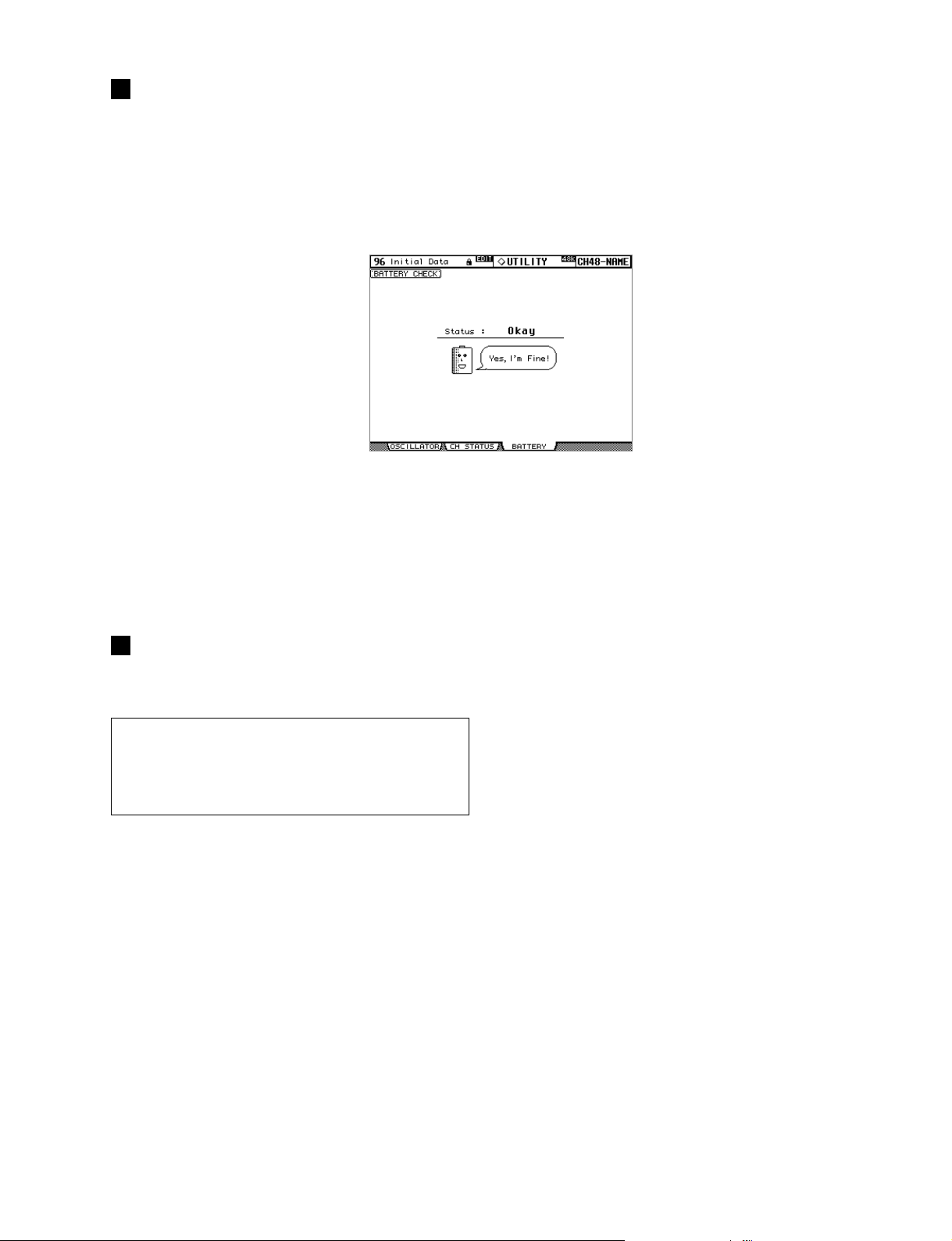
CHECKING THE BATTERY
The condition of the internal memory-backup battery can be
checked as follows.
1 Use the DISPLAY ACCESS [UTILITY] button to
locate the Battery Check page.
If the Status is “Okay,” the battery is okay. If the Status is
“Getting Low,” failure to replace a low battery may result in
data loss.
DM2000
INITIALIZING THE DM2000
The DM2000 can be initialized as follows.
Warning: This procedur e will clear all user memories and r eset
all settings to their initial values. You may want to back up any
important data beforehand via MIDI Bulk Dump (see page 183),
or to SmartMedia (see page 184). If you want to reset just the
mix settings, recall scene memory #0 instead.
1 Turn off the DM2000.
2 While holding down the SCENE MEMORY [STORE]
button, turn on the DM2000.
3 When the confirmation message appears, release
the SCENE MEMORY [STORE] button, select YES,
and press [ENTER].
The following message is displayed while initialization is in
progress: “Loading Factory Presets & Calibrating the Faders...
Do Not Touch the Faders!”
It’s important that you do not touch the faders while this
message is displayed.
The display returns to normal when initialization is complete.
187
Page 88

DM2000
MIDI DATA FORMAT
Scene Memory to Program Change Table
Program
Change #
101 4444 8787
202 4545 8888
303 4646 8989
404 4747 9090
505 4848 9191
606 4949 9292
707 5050 9393
808 5151 9494
909 5252 9595
10 10 53 53 96 96
11 11 54 54 97 97
12 12 55 55 98 98
13 13 56 56 99 99
14 14 57 57 100 00
15 15 58 58 101 —
16 16 59 59 102 —
17 17 60 60 103 —
18 18 61 61 104 —
19 19 62 62 105 —
20 20 63 63 106 —
21 21 64 64 107 —
22 22 65 65 108 —
23 23 66 66 109 —
24 24 67 67 110 —
25 25 68 68 111 —
26 26 69 69 112 —
27 27 70 70 113 —
28 28 71 71 114 —
29 29 72 72 115 —
30 30 73 73 116 —
31 31 74 74 117 —
32 32 75 75 118 —
33 33 76 76 119 —
34 34 77 77 120 —
35 35 78 78 121 —
36 36 79 79 122 —
37 37 80 80 123 —
38 38 81 81 124 —
39 39 82 82 125 —
40 40 83 83 126 —
41 41 84 84 127 —
42 42 85 85 128 —
43 43 86 86
Initial
Scene #
User
Scene #
Program
Change #
Initial
Scene #
User
Scene #
Program
Change#
Initial
Scene #
User
Scene #
188
Page 89

Initial Parameter to Control Change Table
DM2000
# High Mid Low
0 NO ASSIGN
1 FADER H CHANNEL INPUT1
2 FADER H CHANNEL INPUT2
3 FADER H CHANNEL INPUT3
4 FADER H CHANNEL INPUT4
5 FADER H CHANNEL INPUT5
6 FADER H CHANNEL INPUT6
7 FADER H CHANNEL INPUT7
8 FADER H CHANNEL INPUT8
9 FADER H CHANNEL INPUT9
10 FADER H CHANNEL INPUT10
11 FADER H CHANNEL INPUT11
12 FADER H CHANNEL INPUT12
13 FADER H CHANNEL INPUT13
14 FADER H CHANNEL INPUT14
15 FADER H CHANNEL INPUT15
16 FADER H CHANNEL INPUT16
17 FADER H CHANNEL INPUT17
18 FADER H CHANNEL INPUT18
19 FADER H CHANNEL INPUT19
20 FADER H CHANNEL INPUT20
21 FADER H CHANNEL INPUT21
22 FADER H CHANNEL INPUT22
23 FADER H CHANNEL INPUT23
24 FADER H CHANNEL INPUT24
25 FADER H CHANNEL INPUT25
26 FADER H CHANNEL INPUT26
27 FADER H CHANNEL INPUT27
28 FADER H CHANNEL INPUT28
29 FADER H CHANNEL INPUT29
30 FADER H CHANNEL INPUT30
31 FADER H CHANNEL INPUT31
32 NO ASSIGN
33 FADER L CHANNEL INPUT1
34 FADER L CHANNEL INPUT2
35 FADER L CHANNEL INPUT3
36 FADER L CHANNEL INPUT4
37 FADER L CHANNEL INPUT5
38 FADER L CHANNEL INPUT6
39 FADER L CHANNEL INPUT7
40 FADER L CHANNEL INPUT8
41 FADER L CHANNEL INPUT9
42 FADER L CHANNEL INPUT10
43 FADER L CHANNEL INPUT11
44 FADER L CHANNEL INPUT12
45 FADER L CHANNEL INPUT13
46 FADER L CHANNEL INPUT14
47 FADER L CHANNEL INPUT15
48 FADER L CHANNEL INPUT16
49 FADER L CHANNEL INPUT17
50 FADER L CHANNEL INPUT18
51 FADER L CHANNEL INPUT19
52 FADER L CHANNEL INPUT20
53 FADER L CHANNEL INPUT21
54 FADER L CHANNEL INPUT22
55 FADER L CHANNEL INPUT23
56 FADER L CHANNEL INPUT24
57 FADER L CHANNEL INPUT25
58 FADER L CHANNEL INPUT26
59 FADER L CHANNEL INPUT27
# High Mid Low
60 FADER L CHANNEL INPUT28
61 FADER L CHANNEL INPUT29
62 FADER L CHANNEL INPUT30
63 FADER L CHANNEL INPUT31
64 ON CHANNEL INPUT1
65 ON CHANNEL INPUT2
66 ON CHANNEL INPUT3
67 ON CHANNEL INPUT4
68 ON CHANNEL INPUT5
69 ON CHANNEL INPUT6
70 ON CHANNEL INPUT7
71 ON CHANNEL INPUT8
72 ON CHANNEL INPUT9
73 ON CHANNEL INPUT10
74 ON CHANNEL INPUT11
75 ON CHANNEL INPUT12
76 ON CHANNEL INPUT13
77 ON CHANNEL INPUT14
78 ON CHANNEL INPUT15
79 ON CHANNEL INPUT16
80 ON CHANNEL INPUT17
81 ON CHANNEL INPUT18
82 ON CHANNEL INPUT19
83 ON CHANNEL INPUT20
84 ON CHANNEL INPUT21
85 ON CHANNEL INPUT22
86 ON CHANNEL INPUT23
87 ON CHANNEL INPUT24
88 ON CHANNEL INPUT25
89 PAN
PAN
90 CHANNEL INPUT2
91 CHANNEL INPUT3
PAN
92 CHANNEL INPUT4
PAN
93 CHANNEL INPUT5
PAN
94 CHANNEL INPUT6
PAN
95 CHANNEL INPUT7
PAN
96 CHANNEL INPUT8
PAN
PAN
97 CHANNEL INPUT9
PAN
98 CHANNEL INPUT10
99 CHANNEL INPUT11
PAN
100 CHANNEL INPUT12
PAN
101 CHANNEL INPUT13
PAN
PAN
102 CHANNEL INPUT14
PAN
103 CHANNEL INPUT15
PAN
104 CHANNEL INPUT16
PAN
105 CHANNEL INPUT17
PAN
106 CHANNEL INPUT18
PAN
107 CHANNEL INPUT19
108 CHANNEL INPUT20
PAN
109 CHANNEL INPUT21
PAN
110 CHANNEL INPUT22
PAN
111 CHANNEL INPUT23
PAN
PAN
112 CHANNEL INPUT24
PAN
113 CHANNEL INPUT25
PAN
114 CHANNEL INPUT1
PAN
115 CHANNEL INPUT2
PAN
116 CHANNEL INPUT3
117 CHANNEL INPUT4
PAN
118 CHANNEL INPUT5
PAN
PAN
119 CHANNEL INPUT6
CHANNEL INPUT1
189
Page 90

DM2000
MIDI Data Format
1. CHANNEL MESSAGE
Command rx/tx function
8n NOTE OFF rx Control the internal effects
9n NOTE ON rx Control the internal effects
Bn CONTROL CHANGE rx/tx Control parameters
Cn PROGRAM CHANGE rx/tx Switch scene memories
2. SYSTEM COMMON MESSAGE
Command rx/tx function
F1 MIDI TIME CODE QUARTER
FRAME
F2 SONG POSITION POINTER rx
3. SYSTEM REALTIME MESSAGE
Command rx/tx function
F8 TIMING CLOCK rx MIDI clock
FA START rx* Start automix (from the
FB CONTINUE rx* Start automix (from the
FC STOP rx* Stop automix
FE ACTIVE SENSING rx Check MIDI cable connections
FF RESET rx Clear running status
Received only when the Automix TIME REFERENCE setting is
MIDI CLOCK.
4. EXCLUSIVE MESSAGE
4.1 Real Time System Exclusive
Command rx/tx function
F0 7F dd 06 MMC COMMAND tx MMC command (refer to
F0 7F dd 07 MMC RESPONSE rx MMC response(refer to MMC
F0 7F dd 01 MIDI TIME CODE rx
4.2 System Exclusive Message
4.2.1 Bulk Dump
Command rx/tx function
F0 43 0n 7E BULK DUMP DATA rx/tx BULK DUMP DATA
F0 43 2n 7E BULK DUMP REQUEST
The following data types of bulk dump are used on the DM2000.
Data name tx/rx function
'm' tx/rx Scene Memory & Request
'S' tx/rx Setup Memory & Request
'a' tx/rx Automix data & Request
'R' tx/rx Input patch library & Request
'O' tx/rx Output patch library & Request
'H' tx/rx Channel library & Request
'G' tx/rx Gate library & Request
'Y' tx/rx Compressor library & Request
'Q' tx/rx Equalizer library & Request
'E' tx/rx Effect library & Request
'F' tx/rx GEQ library & Request
'J' tx/rx Bus to Stereo library & Request
'K' tx/rx Surround Monitor library & Request
'P' tx/rx Program change table & Request
'C' tx/rx Control change table & Request
'L' tx/rx User define layer & Request
'I' tx/rx Plug-in User define & Request
'V' tx/rx User define key & Request
'N' tx/rx Plug-in Effect Card Data & Request
190
Used when TIME REFERENCE is
rx
MIDI CLOCK.
Used when TIME REFERENCE is
MIDI CLOCK.
beginning)
middle)
MMC specification)
specification)
Usedwhen TIME REFERENCE is
MTC.
rx/tx BULK DUMP REQUEST
4.2.2 PARAMETER CHANGE
Command rx/tx function
F0 43 1n 3E 06 PARAMETER
CHANGE
F0 43 3n 3E 06 PARAMETER
REQUEST
F0 43 1n 3E 7F PARAMETER
CHANGE
F0 43 3n 3E 7F PARAMETER
REQUEST
rx/tx DM2000-specific parameter
change
rx/tx DM2000-specific parameter
request
rx/tx General purpose digital mixer
parameter change
rx/tx General purpose digital mixer
parameter request
The following data types of parameter change are used by the DM2000.
Type tx/rx function
1 tx/rx Edit buffer
2 tx/rx Patch data
3 tx/rx Setup data
4 tx/rx Backup data
16 tx/rx Function (recall, store, title, pair)
32 tx/rx Key remote
33 tx/rx remote meter
34 tx/rx remote counter
4.2.3 Card Filer
Command rx/tx Function
F0 43 5n CARD FILER rx/tx Packet for cardfiler (refer to
Card Filer specification)
** tx means that the data can be transmitted from the DM2000. rx means
that the data can be received by the DM2000.
Format Details
1. NOTE OFF (8n)
Reception
Received when the [Rx CH] matches.
Used to control effects.
STATUS 1000nnnn 8n
DATA 0nnnnnnn nn
0vvvvvvv vv
2. NOTE ON (9n)
Reception
Received when the [Rx CH] matches.
Used to control effects.
STATUS 1001nnnn 9n
DATA 0nnnnnnn nn
0vvvvvvv vv
3. CONTROL CHANGE (Bn)
Reception
Received when [Control Change Rx] is ON and the [Rx CH] matches.
However if [OMNI] is ON, this is received regardless of the channel. If
[Control Change ECHO] is ON, these messages are echoed to MIDI OUT.
If [TABLE] is selected, parameters will be controlled according to the settings of the [Control assign table]. The parameters that can be set are defined in the CONTROL CHANGE ASSIGN PARAMETER LIST. If
[NRPN] is selected, four messages are used to control the defined parameter: NRPN control numbers (62h, 63h) and DATA ENTRY control numbers (06h, 26h). Parameter settings are defined in the CONTROL
CHANGE ASSIGN PARAMETER LIST.
Transmission
If [TABLE] is selected, operating the parameters specified in the [Control
assign table] will cause these messages to be transmitted on the [Tx CH] if
[Control Change TX] is ON. The parameters that can be specified are defined in the CONTROL CHANGE ASSIGN PARAMETER LIST.
If [NRPN] is selected, operating the specified parameters will cause data to
be transmitted on the [Tx CH] if [Control Change TX] is ON, using four
messages: NRPN control numbers (62h, 63h) and DATA ENTRY control
numbers (06h, 26h). Parameter settings are defined in the CONTROL
CHANGE ASSIGN PARAMETER LIST.
Note off message
Note number
Velocity (ignored)
Note on message
Note number
Velocity (1-127:on, 0:off)
Page 91

DM2000
If [TABLE] is selected
STATUS 1011nnnn Bn
DATA 0ccccccc cc
0vvvvvvv vv
Control change
Control number (0-95, 102-119)
Control value (0-127)
If [NRPN] is selected
STATUS 1011nnnn Bn
DATA 01100010 62
STATUS 1011nnnn Bn
DATA 01100011 63
STATUS 1011nnnn Bn
DATA 00100110 26
STATUS 1011nnnn Bn
DATA 00000110 06
*1) There is no particular need to add the 2nd, 3rd, and 4th status
for transmission. However if these are present during reception, they should be received.
*2) Does not need to be transmitted if the parameter data fits
within 7 bits.
0vvvvvvv vv
0vvvvvvv vv
0vvvvvvv vv
0vvvvvvv vv
Control change
NRPN LSB
LSB of parameter number
Control change *1
NRPN MSB
MSB of parameter number
Control change *1
LSB of data entry
LSB of parameter data
Control change *1, *2
MSB of data entry *2
MSB of parameter data *2
4. PROGRAM CHANGE (Cn)
Reception
This message is received if [Program Change RX] is ON and [Rx CH]
matches. However if [OMNI] is ON, this is received regardless of the channel.
A scene memory will be recalled according to the settings of the [Program
Change Table].
This message will be echoed if [Program Change ECHO] is ON.
Transmission
If [Program Change TX] is ON, this message is transmitted according to
the settings of the [Program Change Table] on the [Tx CH] channel when
a scene memory is recalled.
If the recalled scene has been assigned to more than one program number,
the lowest-numbered program number will be transmitted. Transmission
to Studio Manager using Program Change messages will not be performed
since there is no guarantee that the contents of the tables will match. (Parameter Changes will always be used.)
STATUS 1100nnnn Cn
DATA 0nnnnnnn nn
Program change
Program number (0-127)
5. SONG POSITION POINTER (F2)
Reception
If this is received when the automix TIME REFERENCE setting is MIDI
CLOCK, the automix will move to the song position that was received.
STATUS 11110010 F2
DATA 0vvvvvvv vv
0vvvvvvv vv
Song position pointer
Song position LSB
Song position MSB
6. TIMING CLOCK (F8)
Reception
If the automix TIME REFERENCE setting is MIDI CLOCK, this message
is used to synchronize automix. It is also used to control effects. This message is transmitted 24 times per quarter note.
STATUS 11111000 F8
Timing clock
7. START (FA)
Reception
This message is received if the automix TIME REFERENCE setting is MIDI
CLOCK, and will start the automix. In actuality, automix will start when
the next TIMING CLOCK is received after receiving the START message.
STATUS 11111010 FA
Start
8. CONTINUE (FB)
Reception
This message is received if the automix TIME REFERENCE setting is MIDI
CLOCK, and will cause automix to start from the current song position. In
actuality, automix will start when the next TIMING CLOCK is received after receiving the CONTINUE message.
STATUS 11111011 FB
Continue
9. STOP (FC)
Reception
This message is received if the automix TIME REFERENCE setting is MIDI
CLOCK, and will cause automix to stop.
STATUS 11111100 FC
Stop
10. ACTIVE SENSING (FE)
Reception
Once this message has been received, the failure to receive any message for
an interval of 400 ms or longer will cause MIDI transmission to be initialized, such as by clearing the Running Status.
STATUS 11111101 FE
Active sensing
11. SYSTEM RESET (FF)
Reception
When this message is received, MIDI communications will be cleared, e.g.,
by clearing the Running Status.
STATUS 11111111 FF
System reset
12. SYSTEM EXCLUSIVE MESSAGE (F0)
12.1 MIDI MACHINE CONTROL (MMC)
These messages are transmitted when the Machine Control section of the
DM2000 is operated. For details, refer to the MMC specification.
12.2 BULK DUMP
This message sends or receives the contents of various memories stored
within the DM2000.
The basic format is as follows.
For DUMP DATA
F0 43 0n 7E cc cc <Model ID> tt mm mm [Data ...]
cs F7
For DUMP REQUEST
F0 43 2n 7E <Model ID> tt mm mm F7
n
cc cc
<Model ID>
tt
mm mm
cs
A unique header (Model ID) is used to determine whether the device is a
DM2000.
CHECK SUM is obtained by adding the bytes that follow BYTE COUNT
(LOW) and end before CHECK SUM, taking the binary compliment of
this sum, and then setting bit 7 to 0.
CHECK SUM = (-sum)&0x7F
Reception
This message is received if [Bulk RX] is ON and the [Rx CH] matches the
device number included in the SUB STATUS.
When a bulk dump is received, it is immediately written into the specified
memory.
When a bulk dump request is received, a bulk dump is immediately transmitted.
Transmission
This message is transmitted on the [Tx CH] by key operations in the [MIDI]-[BULK DUMP] screen.
A bulk dump is transmitted on the [Rx CH] in response to a bulk dump
Device Number
DATA COUNT (the number of bytes that follow this, ending
before the checksum)
Model ID (for the DM2000, this is 4C 4D 20 20 38 43 31
32)
DATA TYPE
DATA NUMBER
CHECK SUM
191
Page 92

DM2000
request.
The data area is handled by converting seven words of 8-bit data into eight
words of 7-bit data.
[Conversion from actual data into bulk data]
d[0~6]: actual data
b[0~7]: bulk data
b[0] = 0;
for( I=0; I<7; I++){
if( d[I]&0x80){
b[0] |= 1<<(6-I);
}
b[I+1] = d[I]&0x7F;
}
[Restoration from bulk data into actual data]
d[0~6]: actual data
b[0~7]: bulk data
for( I=0; I<7; I++){
b[0] <<= 1;
d[I] = b[I+1]+(0x80&b[0]);
}
12.2.1 Scene memory bulk dump format
The DM2000 can transmit and receive scene memories in compressed
form.
STATUS 11110000 F0
ID No. 01000011 43
SUB STATUS 0000nnnn 0n
FORMAT No. 01111110 7E
COUNT HIGH 0ccccccc ch
System exclusive message
Manufacture's ID number (YAMAHA)
n=0-15 (Device number=MIDI Channel)
Universal bulk dump
data count = ch * 128 + cl
COUNT LOW 0ccccccc cl
01001100 4C
01001101 4D
00100000 20
00100000 20
00111000 38
01000011 43
00110001 31
00110010 32
DATA NAME 01101101 6D
0mmmmmmm mh
0mmmmmmm ml
BLOCK INFO. 0ttttttt tt
0bbbbbbb bb
DATA 0ddddddd ds
'L'
'M'
' '
' '
'8'
'C'
'1'
'2'
'm'
m=0-99, 256(Scene0-99, EDIT BUFFER)
Receive is effective 1-99, 256
total block number(minimum number
is 0)
current block number(0-total block
number)
Scene data of block[mm]
::
0ddddddd de
CHECK SUM 0eeeeeee ee
EOX 11110111 F7
ee=(Invert('L'+...+de)+1)&0x7F
End of exclusive
12.2.2 Scene memory bulk dump request format
The second and third bytes of the DATA NAME indicate the scene number
that is being requested. If this is 256, the data of the edit buffer will be
bulk-dumped.
STATUS 11110000 F0
ID No. 01000011 43
SUB STATUS 0010nnnn 2n
FORMAT No. 01111110 7E
01001100 4C
01001101 4D
00100000 20
00100000 20
00111000 38
01000011 43
00110001 31
00110010 32
DATA NAME 01101101 6D
0mmmmmmm mh
System exclusive message
Manufacture's ID number (YAMAHA)
n=0-15 (Device number=MIDI Channel)
Universal bulk dump
'L'
'M'
' '
' '
'8'
'C'
'1'
'2'
'm'
m=0-99, 256(Scene0-99, EDIT BUFFER)
0mmmmmmm ml
EOX 11110111 F7
End of exclusive
192
12.2.3 Setup memory bulk dump format
Of the setup memory of the DM2000, this bulk-dumps data other than the
User define layer, User define plug-in, User define keys, Control change table, and Program change table.
STATUS 11110000 F0
ID No. 01000011 43
SUB STATUS 0000nnnn 0n
FORMAT No. 01111110 7E
COUNT HIGH 0ccccccc ch
System exclusive message
Manufacture's ID number (YAMAHA)
n=0-15 (Device number=MIDI Channel)
Universal bulk dump
data count = ch * 128 + cl
COUNT LOW 0ccccccc cl
01001100 4C
01001101 4D
00100000 20
00100000 20
00111000 38
01000011 43
00110001 31
00110010 32
DATA NAME 01010011 53
'L'
'M'
' '
' '
'8'
'C'
'1'
'2'
'S'
00000010 02
BLOCK INFO. 0ttttttt tt
00000000 00
0bbbbbbb bb
DATA 0ddddddd ds
No.256 = Current
total block number(minimum number
is 0)
current block number(0-total block
number)
Setup memory data
::
0ddddddd de
CHECK SUM 0eeeeeee ee
EOX 11110111 F7
ee=(Invert('L'+...+de)+1)&0x7F
End of exclusive
12.2.4 Setup memory bulk dump request format
STATUS 11110000 F0
ID No. 01000011 43
SUB STATUS 0010nnnn 2n
FORMAT No. 01111110 7E
01001100 4C
01001101 4D
00100000 20
00100000 20
00111000 38
01000011 43
00110001 31
00110010 32
DATA NAME 01010011 53
00000010 02
00000000 00
EOX 11110111 F7
System exclusive message
Manufacture's ID number (YAMAHA)
n=0-15 (Device number=MIDI Channel)
Universal bulk dump
'L'
'M'
' '
' '
'8'
'C'
'1'
'2'
'S'
No.256 = Current
End of exclusive
12.2.5 User define layer bulk dump format
The second and third bytes of the DATA NAME indicate the bank number.
Be aware that the state of the transmission destination will (in some cases)
change if the same bank is being used.
STATUS 11110000 F0
ID No. 01000011 43
SUB STATUS 0000nnnn 0n
FORMAT No. 01111110 7E
COUNT HIGH 0ccccccc ch
COUNT LOW 0ccccccc cl
01001100 4C
01001101 4D
00100000 20
00100000 20
00111000 38
01000011 43
00110001 31
00110010 32
System exclusive message
Manufacture's ID number (YAMAHA)
n=0-15 (Device number=MIDI Channel)
Universal bulk dump
data count = ch * 128 + cl
'L'
'M'
' '
' '
'8'
'C'
'1'
'2'
Page 93

DM2000
DATA NAME 01001100 4C
'L'
00000000 00
BLOCK INFO. 0ttttttt tt
0bbbbbbb bb
0bbbbbbb bb
DATA 0ddddddd ds
b=0-3(bank no.1-4)
total block number(minimum number
is 0)
current block number(0-total block
number)
User define layer
::
0ddddddd de
CHECK SUM 0eeeeeee ee
EOX 11110111 F7
ee=(Invert('L'+...+de)+1)&0x7F
End of exclusive
12.2.6 User define layer bulk dump request format
The second and third bytes of the DATA NAME indicate the bank number.
STATUS 11110000 F0
ID No. 01000011 43
SUB STATUS 0010nnnn 2n
FORMAT No. 01111110 7E
01001100 4C
01001101 4D
00100000 20
00100000 20
00111000 38
01000011 43
00110001 31
00110010 32
DATA NAME 01001100 4C
System exclusive message
Manufacture's ID number (YAMAHA)
n=0-15 (Device number=MIDI Channel)
Universal bulk dump
'L'
'M'
' '
' '
'8'
'C'
'1'
'2'
'L'
00000000 00
EOX 11110111 F7
0bbbbbbb bb
b=0-3(bank no.1-4)
End of exclusive
12.2.7 User define plug-in bulk dump format
The second and third bytes of the DATA NAME indicate the bank number.
Be aware that the state of the transmission destination will (in some cases)
change if the same bank is being used.
STATUS 11110000 F0
ID No. 01000011 43
SUB STATUS 0000nnnn 0n
FORMAT No. 01111110 7E
COUNT HIGH 0ccccccc ch
System exclusive message
Manufacture's ID number (YAMAHA)
n=0-15 (Device number=MIDI Channel)
Universal bulk dump
data count = ch * 128 + cl
COUNT LOW 0ccccccc cl
01001100 4C
01001101 4D
00100000 20
00100000 20
00111000 38
01000011 43
00110001 31
00110010 32
DATA NAME 01001001 49
'L'
'M'
' '
' '
'8'
'C'
'1'
'2'
'I'
00000000 00
BLOCK INFO. 0ttttttt tt
0bbbbbbb bb
0bbbbbbb bb
DATA 0ddddddd ds
b=0-7(bank no.1-8)
total block number(minimum number
is 0)
current block number(0-total block
number)
User define plug-in data
::
0ddddddd de
CHECK SUM 0eeeeeee ee
EOX 11110111 F7
ee=(Invert('L'+...+de)+1)&0x7F
End of exclusive
12.2.8 User define plug-in bulk dump request format
The second and third bytes of the DATA NAME indicate the bank number.
STATUS 11110000 F0
ID No. 01000011 43
SUB STATUS 0010nnnn 2n
System exclusive message
Manufacture's ID number (YAMAHA)
n=0-15 (Device number=MIDI Channel)
FORMAT No. 01111110 7E
01001100 4C
01001101 4D
00100000 20
00100000 20
00111000 38
01000011 43
00110001 31
00110010 32
DATA NAME 01001001 49
Universal bulk dump
'L'
'M'
' '
' '
'8'
'C'
'1'
'2'
'I'
00000000 00
EOX 11110111 F7
0bbbbbbb bb
b=0-7(bank no.1-8)
End of exclusive
12.2.9 User Define Key bulk dump format
The second and third bytes of the DATA NAME indicate the bank number.
Be aware that the state of the transmission destination will (in some cases)
change if the same bank is being used.
STATUS 11110000 F0
ID No. 01000011 43
SUB STATUS 0000nnnn 0n
FORMAT No. 01111110 7E
COUNT HIGH cccccccc ch
System exclusive message
Manufacture's ID number (YAMAHA)
n=0-15 (Device number=MIDI Channel)
Universal bulk dump
data count = ch * 128 + cl
COUNT LOW cccccccc cl
01001100 4C
01001101 4D
00100000 20
00100000 20
00111000 38
01000011 43
00110001 31
00110010 32
DATA NAME 01010110 56
'L'
'M'
' '
' '
'8'
'C'
'1'
'2'
'V'
00000000 00
BLOCK INFO. 0ttttttt tt
0bbbbbbb bb
0bbbbbbb bb
DATA 0ddddddd ds
b=0-3(bank no.A-D)
total block number(minimum number
is 0)
current block number(0-total block
number)
User define key data
::
0ddddddd de
CHECK SUM 0eeeeeee ee
EOX 11110111 F7
ee=(Invert('L'+...+de)+1)&0x7F
End of exclusive
12.2.10 User Define Key bulk dump request format
The second and third bytes of the DATA NAME indicate the bank number.
STATUS 11110000 F0
ID No. 01000011 43
SUB STATUS 0010nnnn 2n
FORMAT No. 01111110 7E
01001100 4C
01001101 4D
00100000 20
00100000 20
00111000 38
01000011 43
00110001 31
00110010 32
DATA NAME 01010110 56
System exclusive message
Manufacture's ID number (YAMAHA)
n=0-15 (Device number=MIDI Channel)
Universal bulk dump
'L'
'M'
' '
' '
'8'
'C'
'1'
'2'
'V'
BANK No. 00000000 00
EOX 11110111 F7
0bbbbbbb bb
b=0-3(bank no.A-D)
End of exclusive
12.2.11 Control change table bulk dump format
STATUS 11110000 F0
ID No. 01000011 43
SUB STATUS 0000nnnn 0n
System exclusive message
Manufacture's ID number (YAMAHA)
n=0-15 (Device number=MIDI Channel)
193
Page 94

DM2000
FORMAT No. 01111110 7E
COUNT HIGH 00000011 ch
Universal bulk dump
data count = ch * 128 + cl
COUNT LOW 00010010 cl
01001100 4C
01001101 4D
00100000 20
00100000 20
00111000 38
01000011 43
00110001 31
00110010 32
DATA NAME 01000011 43
'L'
'M'
' '
' '
'8'
'C'
'1'
'2'
'C'
00000000 02
BLOCK INFO. 0ttttttt tt
00000000 00
0bbbbbbb bb
DATA 0ddddddd ds
::
No.256 = Current
total block number(minimum number
is 0)
current block number(0-total block
number)
Control change table data
(342/7)*8+(342%7)+1=391bytes
unfixed
0ddddddd de
CHECK SUM 0eeeeeee ee
EOX 11110111 F7
ee=(Invert('L'+...+de)+1)&0x7F
End of exclusive
12.2.12 Control change table bulk dump request
format
STATUS 11110000 F0
ID No. 01000011 43
SUB STATUS 0010nnnn 2n
FORMAT No. 01111110 7E
01001100 4C
01001101 4D
00100000 20
00100000 20
00111000 38
01000011 43
00110001 31
00110010 32
DATA NAME 01000011 43
00000000 02
00000000 00
EOX 11110111 F7
System exclusive message
Manufacture's ID number (YAMAHA)
n=0-15 (Device number=MIDI Channel)
Universal bulk dump
'L'
'M'
' '
' '
'8'
'C'
'1'
'2'
'C'
No.256 = Current
End of exclusive
12.2.13 Program change table bulk dump format
STATUS 11110000 F0
ID No. 01000011 43
SUB STATUS 0000nnnn 0n
FORMAT No. 01111110 7E
COUNT HIGH 0ccccccc ch
COUNT LOW 0ccccccc cl
01001100 4C
01001101 4D
00100000 20
00100000 20
00111000 38
01000011 43
00110001 31
00110010 32
DATA NAME 01010000 50
00000000 02
00000000 00
BLOCK INFO. 0ttttttt tt
0bbbbbbb bb
DATA 0ddddddd ds
::
0ddddddd de
CHECK SUM 0eeeeeee ee
EOX 11110111 F7
System exclusive message
Manufacture's ID number (YAMAHA)
n=0-15 (Device number=MIDI Channel)
Universal bulk dump
data count = ch * 128 + cl
'L'
'M'
' '
' '
'8'
'C'
'1'
'2'
'P'
No.256 = Current
total block number(minimum number
is 0)
current block number(0-total block
number)
Program change table data
ee=(Invert('L'+...+de)+1)&0x7F
End of exclusive
194
12.2.14 Program change table bulk dump request
format
STATUS 11110000 F0
ID No. 01000011 43
SUB STATUS 0010nnnn 2n
FORMAT No. 01111110 7E
01001100 4C
01001101 4D
00100000 20
00100000 20
00111000 38
01000011 43
00110001 31
00110010 32
DATA NAME 01010000 50
00000000 02
00000000 00
EOX 11110111 F7
System exclusive message
Manufacture's ID number (YAMAHA)
n=0-15 (Device number=MIDI Channel)
Universal bulk dump
'L'
'M'
' '
' '
'8'
'C'
'1'
'2'
'P'
No.256 = Current
End of exclusive
12.2.15 Equalizer library bulk dump format
The second and third bytes of the DATA NAME indicate the bank number.
0:Library no.1 - 199:Library no.200, 256:CH1 - 351:CH96, 384:BUS1 391:BUS8, 512:AUX1 - 523:AUX12, 640:MATRIX1L - 647:MATRIX4R,
768:STEREO L - 769:STEREO R
256 and following are data for the corresponding channel of the edit buffer.
For reception by the DM2000, only the user area is valid. (40-199, 256-)
STATUS 11110000 F0
ID No. 01000011 43
SUB STATUS 0000nnnn 0n
FORMAT No. 01111110 7E
COUNT HIGH 0ccccccc ch
System exclusive message
Manufacture's ID number (YAMAHA)
n=0-15 (Device number=MIDI Channel)
Universal bulk dump
data count = ch * 128 + cl
COUNT LOW 0ccccccc cl
01001100 4C
01001101 4D
00100000 20
00100000 20
00111000 38
01000011 43
00110001 31
00110010 32
DATA NAME 01010001 51
LIB. No. H 0bbbbbbb bb
'L'
'M'
' '
' '
'8'
'C'
'1'
'2'
'Q'
0-199(EQ Library no.1-200),
256-(channel current data)
LIB. No. L 0bbbbbbb bb
BLOCK INFO. 0ttttttt tt
0bbbbbbb bb
DATA 0ddddddd ds
total block number(minimum number
is 0)
current block number(0-total block
number)
EQ Library data
::
0ddddddd de
CHECK SUM 0eeeeeee ee
EOX 11110111 F7
ee=(Invert('L'+...+de)+1)&0x7F
End of exclusive
12.2.16 Equalizer library bulk dump request format
The second and third bytes of the DATA NAME indicate the bank number. (See above)
STATUS 11110000 F0
ID No. 01000011 43
SUB STATUS 0010nnnn 2n
FORMAT No. 01111110 7E
01001100 4C
01001101 4D
00100000 20
00100000 20
00111000 38
01000011 43
00110001 31
00110010 32
System exclusive message
Manufacture's ID number (YAMAHA)
n=0-15 (Device number=MIDI Channel)
Universal bulk dump
'L'
'M'
' '
' '
'8'
'C'
'1'
'2'
Page 95

DM2000
DATA NAME 01010001 51
LIB. No. H 0bbbbbbb bb
'Q'
0-199(EQ Library no.1-200),
256-(channel current data)
LIB. No. L 0bbbbbbb bb
EOX 11110111 F7
End of exclusive
12.2.17 Compressor library bulk dump format
The second and third bytes of the DATA NAME indicate the library number.
0:Library no.1 - 127:Library no.128, 256:CH1 - 351:CH96, 384:BUS1 391:BUS8, 512:AUX1 - 523:AUX12, 640:MATRIX1L - 647:MATRIX4R,
768:STEREO L - 769:STEREO R
256 and following are data for the corresponding channel of the edit buffer.
For reception by the DM2000, only the user area is valid. (36-127, 256-)
STATUS 11110000 F0
ID No. 01000011 43
SUB STATUS 0000nnnn 0n
FORMAT No. 01111110 7E
COUNT HIGH 0ccccccc ch
System exclusive message
Manufacture's ID number (YAMAHA)
n=0-15 (Device number=MIDI Channel)
Universal bulk dump
data count = ch * 128 + cl
COUNT LOW 0ccccccc cl
01001100 4C
01001101 4D
00100000 20
00100000 20
00111000 38
01000011 43
00110001 31
00110010 32
DATA NAME 01011001 59
LIB. No. H 0bbbbbbb bb
'L'
'M'
' '
' '
'8'
'C'
'1'
'2'
'Y'
0-127(COMP Library no.1-128),
256-(channel current data)
LIB. No. L 0bbbbbbb bb
BLOCK INFO. 0ttttttt tt
0bbbbbbb bb
DATA 0ddddddd ds
total block number(minimum number
is 0)
current block number(0-total block
number)
COMP Library data
::
0ddddddd de
CHECK SUM 0eeeeeee ee
EOX 11110111 F7
ee=(Invert('L'+...+de)+1)&0x7F
End of exclusive
12.2.18 Compressor library bulk dump request format
The second and third bytes of the DATA NAME indicate the library number. (See above)
STATUS 11110000 F0
ID No. 01000011 43
SUB STATUS 0010nnnn 2n
FORMAT No. 01111110 7E
01001100 4C
01001101 4D
00100000 20
00100000 20
00111000 38
01000011 43
00110001 31
00110010 32
DATA NAME 01011001 59
LIB. No. H 0bbbbbbb bb
System exclusive message
Manufacture's ID number (YAMAHA)
n=0-15 (Device number=MIDI Channel)
Universal bulk dump
'L'
'M'
' '
' '
'8'
'C'
'1'
'2'
'Y'
0-127(COMP Library no.1-128),
256-(channel current data)
LIB. No. L 0bbbbbbb bb
EOX 11110111 F7
End of exclusive
12.2.19 Gate library bulk dump format
The second and third bytes of the DATA NAME indicate the library number.
0:Library no.1 - 127:Library no.128, 256:CH1 - 351:CH96
256 and following are data for the corresponding channel of the edit buffer.
For reception by the DM2000, only the user area is valid. (4-127, 256-)
STATUS 11110000 F0
System exclusive message
ID No. 01000011 43
SUB STATUS 0000nnnn 0n
FORMAT No. 01111110 7E
COUNT HIGH 0ccccccc ch
Manufacture's ID number (YAMAHA)
n=0-15 (Device number=MIDI
Channel)
Universal bulk dump
data count = ch * 128 + cl
COUNT LOW 0ccccccc cl
01001100 4C
01001101 4D
00100000 20
00100000 20
00111000 38
01000011 43
00110001 31
00110010 32
DATA NAME 01000111 47
LIB. No. H 0bbbbbbb bh
'L'
'M'
' '
' '
'8'
'C'
'1'
'2'
'G'
0-127(GATE Library no.1-128),
256-351(channel current data)
LIB. No. L 0bbbbbbb bl
BLOCK INFO. 0ttttttt tt
0bbbbbbb bb
DATA 0ddddddd ds
total block number(minimum number
is 0)
current block number(0-total block
number)
GATE Library data
::
0ddddddd de
CHECK SUM 0eeeeeee ee
EOX 11110111 F7
ee=(Invert('L'+...+de)+1)&0x7F
End of exclusive
12.2.20 Gate library bulk dump request format
The second and third bytes of the DATA NAME indicate the library number. (See above)
STATUS 11110000 F0
ID No. 01000011 43
SUB STATUS 0010nnnn 2n
FORMAT No. 01111110 7E
01001100 4C
01001101 4D
00100000 20
00100000 20
00111000 38
01000011 43
00110001 31
00110010 32
DATA NAME 01000111 47
LIB. No. H 0bbbbbbb bh
System exclusive message
Manufacture's ID number (YAMAHA)
n=0-15 (Device number=MIDI Channel)
Universal bulk dump
'L'
'M'
' '
' '
'8'
'C'
'1'
'2'
'G'
0-127(GATE Library no.1-128),
256-351(channel current data)
LIB. No. L 0bbbbbbb bl
EOX 11110111 F7
End of exclusive
12.2.21 Effect library bulk dump format
The second and third bytes of the DATA NAME indicate the library number.
0:Library no.1 - 127:Library no.128, 256:EFFECT1 - 263:EFFEC8
256-263 are the data for the corresponding area of the edit buffer.
For reception by the DM2000, only the user area is valid. (52-127,
256-263)
STATUS 11110000 F0
ID No. 01000011 43
SUB STATUS 0000nnnn 0n
FORMAT No. 01111110 7E
COUNT HIGH 0ccccccc ch
COUNT LOW 0ccccccc cl
01001100 4C
01001101 4D
00100000 20
00100000 20
00111000 38
01000011 43
00110001 31
00110010 32
DATA NAME 01000110 46
System exclusive message
Manufacture's ID number (YAMAHA)
n=0-15 (Device number=MIDI Channel)
Universal bulk dump
data count = ch * 128 + cl
'L'
'M'
' '
' '
'8'
'C'
'1'
'2'
'E'
195
Page 96

DM2000
LIB. No. H 0bbbbbbb bh
0-127(Effect Library no.1-128),
256-263(Effect1-8 current)
LIB. No. L 0bbbbbbb bl
BLOCK INFO. 0ttttttt tt
0bbbbbbb bb
DATA 0ddddddd ds
total block number(minimum number
is 0)
current block number(0-total block
number)
Effect Library data
::
0ddddddd de
CHECK SUM 0eeeeeee ee
EOX 11110111 F7
ee=(Invert('L'+...+de)+1)&0x7F
End of exclusive
12.2.22 Effect library bulk dump request format
The second and third bytes of the DATA NAME indicate the library number. (See above)
STATUS 11110000 F0
ID No. 01000011 43
SUB STATUS 0010nnnn 2n
FORMAT No. 01111110 7E
01001100 4C
01001101 4D
00100000 20
00100000 20
00111000 38
01000011 43
00110001 31
00110010 32
DATA NAME 01000110 46
LIB. No. H 0bbbbbbb bh
System exclusive message
Manufacture's ID number (YAMAHA)
n=0-15 (Device number=MIDI Channel)
Universal bulk dump
'L'
'M'
' '
' '
'8'
'C'
'1'
'2'
'E'
0-127(Effect Library no.1-128),
256-263(Effect1-8 current)
LIB. No. L 0bbbbbbb bl
EOX 11110111 F7
End of exclusive
12.2.23 GEQ library bulk dump format
The second and third bytes of the DATA NAME indicate the library number.
0:Library no.0 - 128:Library no.128, 256:GEQ1 - 261:GEQ6
256-261 are the data for the corresponding area of the edit buffer.
For reception by the DM2000, only the user area is valid. (1-128, 256-261)
STATUS 11110000 F0
ID No. 01000011 43
SUB STATUS 0000nnnn 0n
FORMAT No. 01111110 7E
COUNT HIGH 0ccccccc ch
System exclusive message
Manufacture's ID number (YAMAHA)
n=0-15 (Device number=MIDI Channel)
Universal bulk dump
data count = ch * 128 + cl
COUNT LOW 0ccccccc cl
01001100 4C
01001101 4D
00100000 20
00100000 20
00111000 38
01000011 43
00110001 31
00110010 32
DATA NAME 01000111 47
LIB. No. H 0bbbbbbb bh
'L'
'M'
' '
' '
'8'
'C'
'1'
'2'
'F'
0-128(GEQ Library no.0-128),
256-261(GEQ1-6 Current)
LIB. No. L 0bbbbbbb bl
BLOCK INFO. 0ttttttt tt
0bbbbbbb bb
DATA 0ddddddd ds
total block number(minimum number
is 0)
current block number(0-total block
number)
GEQ Library data
::
0ddddddd de
CHECK SUM 0eeeeeee ee
EOX 11110111 F7
ee=(Invert('L'+...+de)+1)&0x7F
End of exclusive
12.2.24 GEQ library bulk dump request format
The second and third bytes of the DATA NAME indicate the library number. (See above)
STATUS 11110000 F0
System exclusive message
196
ID No. 01000011 43
SUB STATUS 0010nnnn 2n
FORMAT No. 01111110 7E
01001100 4C
01001101 4D
00100000 20
00100000 20
00111000 38
01000011 43
00110001 31
00110010 32
DATA NAME 01000111 47
LIB. No. H 0bbbbbbb bh
Manufacture's ID number (YAMAHA)
n=0-15 (Device number=MIDI Channel)
Universal bulk dump
'L'
'M'
' '
' '
'8'
'C'
'1'
'2'
'F'
0-128(GEQ Library no.0-128),
256-261(GEQ1-6 current)
LIB. No. L 0bbbbbbb bl
EOX 11110111 F7
End of exclusive
12.2.25 Channel library bulk dump format
The second and third bytes of the DATA NAME indicate the library number.
0:Library no.0 - 128:Library no.128,
256:CH1 - 351:CH96, 384:BUS1 - 391:BUS8, 512:AUX1 - 523:AUX12,
640:MATRIX1L - 647:MATRIX4R, 768:STEREO L - 769:STEREO R
256 and following are the data for the corresponding channel of the edit
buffer.
For reception by the DM2000, only the user area is valid. (2-128, 256-)
STATUS 11110000 F0
ID No. 01000011 43
SUB STATUS 0000nnnn 0n
FORMAT No. 01111110 7E
COUNT HIGH 0ccccccc ch
System exclusive message
Manufacture's ID number (YAMAHA)
n=0-15 (Device number=MIDI Channel)
Universal bulk dump
data count = ch * 128 + cl
COUNT LOW 0ccccccc cl
01001100 4C
01001101 4D
00100000 20
00100000 20
00111000 38
01000011 43
00110001 31
00110010 32
DATA NAME 01001001 49
LIB. No. H 0bbbbbbb bh
'L'
'M'
' '
' '
'8'
'C'
'1'
'2'
'H'
0-128(Channel Library no.0-128),
256-(current)
LIB. No. L 0bbbbbbb bl
BLOCK INFO. 0ttttttt tt
0bbbbbbb bb
DATA 0ddddddd ds
total block number(minimum number
is 0)
current block number(0-total block
number)
channel Library data
::
0ddddddd de
CHECK SUM 0eeeeeee ee
EOX 11110111 F7
ee=(Invert('L'+...+de)+1)&0x7F
End of exclusive
12.2.26 Channel library bulk dump request format
The second and third bytes of the DATA NAME indicate the library number. (See above)
STATUS 11110000 F0
ID No. 01000011 43
SUB STATUS 0010nnnn 2n
FORMAT No. 01111110 7E
01001100 4C
01001101 4D
00100000 20
00100000 20
00111000 38
01000011 43
00110001 31
00110010 32
DATA NAME 01001001 49
LIB. No. H 0bbbbbbb bh
System exclusive message
Manufacture's ID number (YAMAHA)
n=0-15 (Device number=MIDI Channel)
Universal bulk dump
'L'
'M'
' '
' '
'8'
'C'
'1'
'2'
'H'
0-128(Channel Library no.0-128),
256-(current)
Page 97

DM2000
LIB. No. L 0bbbbbbb bl
EOX 11110111 F7
End of exclusive
12.2.27 Input patch library bulk dump format
The second and third bytes of the DATA NAME indicate the library number.
0:Library no.0 - 32:Library no.32, 256:current input patch data
For reception by the DM2000, only the user area is valid. (1-32, 256)
STATUS 11110000 F0
ID No. 01000011 43
SUB STATUS 0000nnnn 0n
FORMAT No. 01111110 7E
COUNT HIGH 0ccccccc ch
System exclusive message
Manufacture's ID number (YAMAHA)
n=0-15 (Device number=MIDI Channel)
Universal bulk dump
data count = ch * 128 + cl
COUNT LOW 0ccccccc cl
01001100 4C
01001101 4D
00100000 20
00100000 20
00111000 38
01000011 43
00110001 31
00110010 32
DATA NAME 01010010 52
0bbbbbbb bh
'L'
'M'
' '
' '
'8'
'C'
'1'
'2'
'R'
0-32(Library no.0-32), 256(Current
data)
0bbbbbbb bl
BLOCK INFO. 0ttttttt tt
0bbbbbbb bb
DATA 0ddddddd ds
total block number(minimum number
is 0)
current block number(0-total block
number)
Input Patch Library data
::
0ddddddd de
CHECK SUM 0eeeeeee ee
EOX 11110111 F7
ee=(Invert('L'+...+de)+1)&0x7F
End of exclusive
12.2.28 Input patch library bulk dump request format
The second and third bytes of the DATA NAME indicate the library number.
0:Library no.0 - 32:Library no.32, 256:current input patch data
STATUS 11110000 F0
ID No. 01000011 43
SUB STATUS 0010nnnn 2n
FORMAT No. 01111110 7E
01001100 4C
01001101 4D
00100000 20
00100000 20
00111000 38
01000011 43
00110001 31
00110010 32
DATA NAME 01010010 52
0bbbbbbb bh
System exclusive message
Manufacture's ID number (YAMAHA)
n=0-15 (Device number=MIDI Channel)
Universal bulk dump
'L'
'M'
' '
' '
'8'
'C'
'1'
'2'
'R'
0-32(Library no.0-32), 256(Current
data)
0bbbbbbb bl
EOX 11110111 F7
End of exclusive
12.2.29 Output patch library bulk dump format
The second and third bytes of the DATA NAME indicate the library number.
0:Library no.0 - 32:Library no.32, 256:current output patch data
For reception by the DM2000, only the user area is valid. (1-32, 256)
STATUS 11110000 F0
ID No. 01000011 43
SUB STATUS 0000nnnn 0n
FORMAT No. 01111110 7E
COUNT HIGH 0ccccccc ch
COUNT LOW 0ccccccc cl
01001100 4C
01001101 4D
System exclusive message
Manufacture's ID number (YAMAHA)
n=0-15 (Device number=MIDI Channel)
Universal bulk dump
data count = ch * 128 + cl
'L'
'M'
00100000 20
00100000 20
00111000 38
01000011 43
00110001 31
00110010 32
DATA NAME 01001111 4F
0bbbbbbb bh
' '
' '
'8'
'C'
'1'
'2'
'O'
0-32(Library no.0-32), 256(Current
data)
00100000 bl
BLOCK INFO. 0ttttttt tt
0bbbbbbb bb
DATA 0ddddddd ds
total block number(minimum number
is 0)
current block number(0-total block
number)
Input Patch Library data
::
0ddddddd de
CHECK SUM 0eeeeeee ee
EOX 11110111 F7
ee=(Invert('L'+...+de)+1)&0x7F
End of exclusive
12.2.30 Output patch library bulk dump request format
The second and third bytes of the DATA NAME indicate the library number.
0:Library no.0 - 32:Library no.32, 256:current output patch data
STATUS 11110000 F0
ID No. 01000011 43
SUB STATUS 0010nnnn 2n
FORMAT No. 01111110 7E
01001100 4C
01001101 4D
00100000 20
00100000 20
00111000 38
01000011 43
00110001 31
00110010 32
DATA NAME 01001111 4F
0bbbbbbb bh
System exclusive message
Manufacture's ID number (YAMAHA)
n=0-15 (Device number=MIDI Channel)
Universal bulk dump
'L'
'M'
' '
' '
'8'
'C'
'1'
'2'
'O'
0-32(Library no.0-32), 256(Current
data)
0bbbbbbb bl
EOX 11110111 F7
End of exclusive
12.2.31 Bus to Stereo library bulk dump format
The second and third bytes of the DATA NAME indicate the library number.
0:Library no.0 - 32:Library no.32, 256:current data
For reception by the DM2000, only the user area is valid.
STATUS 11110000 F0
ID No. 01000011 43
SUB STATUS 0000nnnn 0n
FORMAT No. 01111110 7E
COUNT HIGH 0ccccccc ch
COUNT LOW 0ccccccc cl
01001100 4C
01001101 4D
00100000 20
00100000 20
00111000 38
01000011 43
00110001 31
00110010 32
DATA NAME 01001010 4A
0bbbbbbb bh
0bbbbbbb bl
BLOCK INFO. 0ttttttt tt
0bbbbbbb bb
DATA 0ddddddd ds
::
0ddddddd de
System exclusive message
Manufacture's ID number (YAMAHA)
n=0-15 (Device number=MIDI Channel)
Universal bulk dump
data count = ch * 128 + cl
'L'
'M'
' '
' '
'8'
'C'
'1'
'2'
'J'
0-32(Library no.0-32), 256(Current
data)
total block number(minimum number
is 0)
current block number(0-total block
number)
Input Patch Library data
197
Page 98

DM2000
CHECK SUM 0eeeeeee ee
EOX 11110111 F7
ee=(Invert('L'+...+de)+1)&0x7F
End of exclusive
12.2.32 Bus to Stereo library bulk dump request format
The second and third bytes of the DATA NAME indicate the library number.
0:Library no.0 - 32:Library no.32, 256:current data
STATUS 11110000 F0
ID No. 01000011 43
SUB STATUS 0010nnnn 2n
FORMAT No. 01111110 7E
01001100 4C
01001101 4D
00100000 20
00100000 20
00111000 38
01000011 43
00110001 31
00110010 32
DATA NAME 01001010 4A
0bbbbbbb bh
System exclusive message
Manufacture's ID number (YAMAHA)
n=0-15 (Device number=MIDI Channel)
Universal bulk dump
'L'
'M'
' '
' '
'8'
'C'
'1'
'2'
'J'
0-32 (Library no.0-32), 256 (Current
data)
0bbbbbbb bl
EOX 11110111 F7
End of exclusive
12.2.33 Surround Monitor library bulk dump format
The second and third bytes of the DATA NAME indicate the library number.
0:Library no.0 - 32:Library no.32, 256:current data
For reception by the DM2000, only the user area is valid. (1-32, 256)
STATUS 11110000 F0
ID No. 01000011 43
SUB STATUS 0000nnnn 0n
FORMAT No. 01111110 7E
COUNT HIGH 0ccccccc ch
System exclusive message
Manufacture's ID number (YAMAHA)
n=0-15 (Device number=MIDI Channel)
Universal bulk dump
data count = ch * 128 + cl
COUNT LOW 0ccccccc cl
01001100 4C
01001101 4D
00100000 20
00100000 20
00111000 38
01000011 43
00110001 31
00110010 32
DATA NAME 01001011 4B
0bbbbbbb bh
'L'
'M'
' '
' '
'8'
'C'
'1'
'2'
'K'
0-32(Library no.0-32), 256(Current
data)
0bbbbbbb bl
BLOCK INFO. 0ttttttt tt
0bbbbbbb bb
DATA 0ddddddd ds
total block number(minimum number
is 0)
current block number(0-total block
number)
Input Patch Library data
::
0ddddddd de
CHECK SUM 0eeeeeee ee
EOX 11110111 F7
ee=(Invert('L'+...+de)+1)&0x7F
End of exclusive
12.2.34 Surround Monitor library bulk dump request
format
The second and third bytes of the DATA NAME indicate the library number.
0:Library no.0 - 32:Library no.32, 256:current data
STATUS 11110000 F0
ID No. 01000011 43
SUB STATUS 0010nnnn 2n
FORMAT No. 01111110 7E
01001100 4C
01001101 4D
00100000 20
00100000 20
System exclusive message
Manufacture's ID number (YAMAHA)
n=0-15 (Device number=MIDI Channel)
Universal bulk dump
'L'
'M'
' '
' '
198
00111000 38
01000011 43
00110001 31
00110010 32
DATA NAME 01001011 4B
0bbbbbbb bh
'8'
'C'
'1'
'2'
'K'
0-32(Library no.0-32), 256(Current
data)
0bbbbbbb bl
EOX 11110111 F7
End of exclusive
12.2.35 Plug-in effect card bulk dump format
The second byte of the DATA NAME indicates the slot number.
0:SLOT 1 - 5:SLOT 6
The data is not received if the Developer ID and Product ID are different
than the card that is installed in the slot.
The data is not transmitted if a valid plug-in effect card is not installed.
STATUS 11110000 F0
ID No. 01000011 43
SUB STATUS 0000nnnn 0n
FORMAT No. 01111110 7E
COUNT HIGH 0ccccccc ch
System exclusive message
Manufacture's ID number (YAMAHA)
n=0-15 (Device number=MIDI Channel)
Universal bulk dump
data count = ch * 128 + cl
COUNT LOW 0ccccccc cl
01001100 4C
01001101 4D
00100000 20
00100000 20
00111000 38
01000011 43
00110001 31
00110010 32
DATA NAME 01000001 41
0mmmmmmm mh
'L'
'M'
' '
' '
'8'
'C'
'1'
'2'
'N'
0-5 (SLOT1-6)
0mmmmmmm ml
DATA 0xxxxxxx xh
0xxxxxxx xl
0yyyyyyy yh
0yyyyyyy yl
0000iiii
0000iiii
0000jjjj
0000jjjj
0ddddddd ds
::
block count (High)
block count (Low)
total size (High)
total size (Low)
Developer id (High)
Developer id (Low)
Product id (High)
Product id (Low)
Plug-in Effect card memory data
(1024/7)*8+(1024%7)+1=1171bytes
0ddddddd de
CHECK SUM 0eeeeeee ee
EOX 11110111 F7
ee=(Invert('L'+...+de)+1)&0x7F
End of exclusive
12.2.36 Plug-in effect card bulk dump request format
The second byte of the DATA NAME indicates the library number.
0:SLOT 1 - 5:SLOT 6
STATUS 11110000 F0
ID No. 01000011 43
SUB STATUS 0010nnnn 2n
FORMAT No. 01111110 7E
01001100 4C
01001101 4D
00100000 20
00100000 20
00111000 38
01000011 43
00110001 31
00110010 32
DATA NAME 01000001 41
0mmmmmmm mm
0mmmmmmm ml
EOX 11110111 F7
System exclusive message
Manufacture's ID number (YAMAHA)
n=0-15 (Device number=MIDI Channel)
Universal bulk dump
'L'
'M'
' '
' '
'8'
'C'
'1'
'2'
'A'
0-5 (SLOT1-6)
End of exclusive
Page 99

DM2000
12.3 PARAMETER CHANGE
12.3.1 Parameter change basic format
STATUS 11110000 F0
ID No. 01000011 43
SUB STATUS 0001nnnn 1n
GROUP ID 00111110 3E
MODEL ID 00000110 06
ADDRESS 0ttttttt tt
0eeeeeee ee
0ppppppp pp
0ccccccc cc
DATA *) 0ddddddd dd
::
EOX 11110111 F7
For parameters with a data size of 2 or more, data for that size
will be transmitted.
12.3.2 Parameter Change basic format (Universal
format)
STATUS 11110000 F0
ID No. 01000011 43
SUB STATUS 0001nnnn 1n
GROUP ID 00111110 3E
MODEL ID 01111111 7F
ADDRESS 0ttttttt tt
0eeeeeee ee
0ppppppp pp
0ccccccc cc
DATA *) 0ddddddd dd
::
EOX 11110111 F7
For parameters with a data size of 2 or more, data for that size
will be transmitted.
12.3.3 Parameter request basic format
STATUS 11110000 F0
ID No. 01000011 43
SUB STATUS 0011nnnn 3n
GROUP ID 00111110 3E
MODEL ID 00000110 06
ADDRESS 0ttttttt tt
0eeeeeee ee
0ppppppp pp
0ccccccc cc
EOX 11110111 F7
12.3.4 Parameter request basic format (Universal
format)
STATUS 11110000 F0
ID No. 01000011 43
SUB STATUS 0011nnnn 3n
GROUP ID 00111110 3E
MODEL ID 01111111 7F
ADDRESS 0ttttttt tt
0eeeeeee ee
0ppppppp pp
0ccccccc cc
EOX 11110111 F7
12.3.5 Parameter Address
Consult your dealer for parameter address details.
12.3.6 Parameter change (Edit buffer)
System exclusive message
Manufacture's ID number (YAMAHA)
n=0-15 (Device number=MIDI Channel)
MODEL ID (digital mixer)
DM2000
Data type
Element No.
(If ‘ee’ is 0, ‘ee’ is expanded to two
bytes)
Parameter No.
Channel No.
Data
End of exclusive
System exclusive message
Manufacture's ID number (YAMAHA)
n=0-15 (Device number=MIDI Channel)
MODEL ID (digital mixer)
Universal
Data type
Element No.
(If ‘ee’ is 0, ‘ee’ is expanded to two
bytes)
Parameter No.
Channel No.
Data
End of exclusive
System exclusive message
Manufacture's ID number (YAMAHA)
n=0-15 (Device number=MIDI Channel)
MODEL ID (digital mixer)
DM2000
Data type
Element No.
(If ‘ee’ is 0, ‘ee’ is expanded to two
bytes)
Parameter No.
Channel No.
End of exclusive
System exclusive message
Manufacture's ID number (YAMAHA)
n=0-15 (Device number=MIDI Channel)
MODEL ID (digital mixer)
Universal
Data type
Element No.
(If ‘ee’ is 0, ‘ee’ is expanded to two
bytes)
Parameter No.
Channel No.
End of exclusive
Reception
This is received if [Parameter change RX] is ON and the [Rx CH] matches
the device number included in the SUB STATUS.
This is echoed if [Parameter change ECHO] is ON.
When this is received, the specified parameter will be controlled.
Transmission
If [Parameter change TX] is ON and a parameter not specified in the
[Control assign table] is modified, this message will be transmitted with
the device number specified by the [Tx CH].
STATUS 11110000 F0
ID No. 01000011 43
SUB STATUS 0001nnnn 1n
GROUP ID 00111110 3E
MODEL ID 01111111 7F
ADDRESS 00000001 01
0eeeeeee ee
0ppppppp pp
0ccccccc cc
DATA 0ddddddd dd
System exclusive message
Manufacture's ID number (YAMAHA)
n=0-15 (Device number=MIDI Channel)
MODEL ID (digital mixer)
Universal
Edit Buffer
Element No.
(If ‘ee’ is 0, ‘ee’ is expanded to two
bytes)
Parameter No.
Channel No.
Data
::
EOX 11110111 F7
End of exclusive
12.3.7 Parameter request (Edit buffer)
Reception
This is received if [Parameter change RX] is ON and the [Rx CH] matches
the device number included in the SUB STATUS.
This is echoed if [Parameter change ECHO] is ON.
When this is received, the value of the specified parameter will be transmitted as a Parameter Change.
STATUS 11110000 F0
ID No. 01000011 43
SUB STATUS 0011nnnn 3n
GROUP ID 00111110 3E
MODEL ID 01111111 7F
ADDRESS 00000001 01
0eeeeeee ee
0ppppppp pp
0ccccccc cc
EOX 11110111 F7
System exclusive message
Manufacture's ID number (YAMAHA)
n=0-15 (Device number=MIDI Channel)
MODEL ID (digital mixer)
Universal
Edit Buffer
Element No.
(If ‘ee’ is 0,‘ee’ is expanded to two
bytes)
Parameter No.
Channel No.
End of exclusive
12.3.8 Parameter change (Patch data)
Reception
This is received if [Parameter change RX] is ON and the [Rx CH] matches
the device number included in the SUB STATUS.
This is echoed if [Parameter change ECHO] is ON.
When this is received, the specified parameter will be controlled.
STATUS 11110000 F0
ID No. 01000011 43
SUB STATUS 0001nnnn 1n
GROUP ID 00111110 3E
MODEL ID 00000110 06
ADDRESS 00000010 02
0eeeeeee ee
0ppppppp pp
0ccccccc cc
DATA 0ddddddd dd
System exclusive message
Manufacture's ID number (YAMAHA)
n=0-15 (Device number=MIDI Channel)
MODEL ID (digital mixer)
DM2000
Patch data
Element No.
(If ‘ee’ is 0, ‘ee’ is expanded to two
bytes)
Parameter No.
Channel No.
Data
::
EOX 11110111 F7
End of exclusive
12.3.9 Parameter request (Patch data)
Reception
This is received if [Parameter change RX] is ON and the [Rx CH] matches
the device number included in the SUB STATUS.
This is echoed if [Parameter change ECHO] is ON.
When this is received, the value of the specified parameter will be transmitted as a Parameter Change.
STATUS 11110000 F0
System exclusive message
199
Page 100

DM2000
ID No. 01000011 43
SUB STATUS 0011nnnn 3n
GROUP ID 00111110 3E
MODEL ID 00000110 06
ADDRESS 00000010 02
0eeeeeee ee
0ppppppp pp
0ccccccc cc
EOX 11110111 F7
Manufacture's ID number (YAMAHA)
n=0-15 (Device number=MIDI Channel)
MODEL ID (digital mixer)
DM2000
Patch data
Element No.
(If ‘ee’ is 0, ‘ee’ is expanded to two
bytes)
Parameter No.
Channel No.
End of exclusive
12.3.10 Parameter change (Setup memory)
Reception
This is received if [Parameter change RX] is ON and the [Rx CH] matches
the device number included in the SUB STATUS.
This is echoed if [Parameter change ECHO] is ON.
When this is received, the value of the specified parameter will be controlled.
STATUS 11110000 F0
ID No. 01000011 43
SUB STATUS 0001nnnn 1n
GROUP ID 00111110 3E
MODEL ID 00000110 06
ADDRESS 00000011 03
0eeeeeee ee
0ppppppp pp
0ccccccc cc
DATA 0ddddddd dd
System exclusive message
Manufacture's ID number (YAMAHA)
n=0-15 (Device number=MIDI Channel)
MODEL ID (digital mixer)
DM2000
Setup memory
Element No.
(If ‘ee’ is 0, ‘ee’ is expanded to two
bytes)
Parameter No.
Channel No.
Data
::
EOX 11110111 F7
End of exclusive
12.3.11 Parameter request (Setup memory)
Reception
This is received if [Parameter change RX] is ON and the [Rx CH] matches
the device number included in the SUB STATUS.
This is echoed if [Parameter change ECHO] is ON.
When this is received, the value of the specified parameter will be transmitted as a Parameter Change.
STATUS 11110000 F0
ID No. 01000011 43
SUB STATUS 0011nnnn 3n
GROUP ID 00111110 3E
MODEL ID 00000110 06
ADDRESS 00000011 03
0eeeeeee ee
0ppppppp pp
0ccccccc cc
EOX 11110111 F7
System exclusive message
Manufacture's ID number (YAMAHA)
n=0-15 (Device number=MIDI Channel)
MODEL ID (digital mixer)
DM2000
Setup memory
Element No.
(If ‘ee’ is 0, ‘ee’ is expanded to two
bytes)
Parameter No.
Channel No.
End of exclusive
12.3.12 Parameter change (Backup memory)
Reception
This is received if [Parameter change RX] is ON and the [Rx CH] matches
the device number included in the SUB STATUS.
This is echoed if [Parameter change ECHO] is ON.
When this is received, the value of the specified parameter will be controlled.
STATUS 11110000 F0
ID No. 01000011 43
SUB STATUS 0001nnnn 1n
GROUP ID 00111110 3E
MODEL ID 00000110 06
ADDRESS 00000100 04
0aaaaaaa ee
0aaaaaaa pp
0ccccccc cc
DATA 0ddddddd dd
System exclusive message
Manufacture's ID number (YAMAHA)
n=0-15 (Device number=MIDI Channel)
MODEL ID (digital mixer)
DM2000
Backup memory
Element No.
Parameter No.
Channel No.
Data
::
200
EOX 11110111 F7
End of exclusive
12.3.13 Parameter request (Backup memory)
Reception
This is received if [Parameter change RX] is ON and the [Rx CH] matches
the device number included in the SUB STATUS.
This is echoed if [Parameter change ECHO] is ON.
When this is received, the value of the specified parameter will be transmitted as a Parameter Change.
STATUS 11110000 F0
ID No. 01000011 43
SUB STATUS 0011nnnn 3n
GROUP ID 00111110 3E
MODEL ID 00000110 06
ADDRESS 00000100 04
0aaaaaaa ee
0aaaaaaa pp
0ccccccc cc
EOX 11110111 F7
System exclusive message
Manufacture's ID number (YAMAHA)
n=0-15 (Device number=MIDI Channel)
MODEL ID (digital mixer)
DM2000
Backup memory
Element No.
Parameter No.
Channel No.
End of exclusive
12.3.14 Parameter change (Function call Library:
store/recall)
Reception
This is received if [Parameter change RX] is ON and the [Rx CH] matches
the device number included in the SUB STATUS.
This is echoed if [Parameter change ECHO] is ON.
When this is received, the specified memory/library will be stored/recalled.
Transmission
If [Parameter change ECHO] is ON, this message will be retransmitted
without change.
STATUS 11110000 F0
ID No. 01000011 43
SUB STATUS 0001nnnn 1n
GROUP ID 00111110 3E
MODEL ID 00000110 7F
ADDRESS 00010000 10
00ffffff ff
0aaaaaaa aa
0aaaaaaa aa
DATA 0ddddddd dd
0ddddddd dd
EOX 11110111 F7
function number channel*1) tx/rx
SCENE RECALL 0x00 0-99 256 tx*2)/r
EQ LIB RECALL 0x01 1-200 0-513 tx/rx
GATE LIB RECALL 0x02 1-128 0-95 tx/rx
COMP LIB RECALL 0x03 1-128 0-513 tx/rx
EFF LIB RECALL 0x04 1-128 0-7 tx/rx
GEQ LIB RECALL 0x05 0-128 0-5 tx/rx
CHANNEL LIB RECALL 0x06 0-128 0-513 tx/rx
INPATCH LIB RECALL 0x07 0-32 256 tx/rx
OUTPATCH LIB RECALL 0x08 0-32 256 tx/rx
Bus to Stereo LIB RECALL 0x09 0-32 256 tx/rx
Surround Monitor LIB RECALL 0x0A 0-32 256 tx/rx
AUTOMIX LIB RECALL 0x0B 1-16 256 tx/rx
SCENE STORE 0x20 1-99 256, 16383 tx/rx
EQ LIB STORE 0x21 41-200 0-513, 16383 tx/rx
GATE LIB STORE 0x22 5-128 0-96, 16383 tx/rx
COMP LIB STORE 0x23 37-128 0-513, 16383 tx/rx
EFF LIB STORE 0x24 53-128 0-7, 16383 tx/rx
GEQ LIB STORE 0x25 1-128 0-5, 16383 tx/rx
CHANNEL LIB STORE 0x26 3-128 0-513, 16383 tx/rx
INPATCH LIB STORE 0x27 1-32 256, 16383 tx/rx
OUTPATCH LIB STORE 0x28 1-32 256, 16383 tx/rx
Bus to Stereo LIB STORE 0x29 1-32 256, 16383 tx/rx
Surround Monitor LIB STORE 0x2A 1-32 256, 16383 tx/rx
AUTOMIX LIB STORE 0x2B 1-32 256, 16383 tx/rx
*1) 0:CH1 - 95:CH96, 128:BUS1 - 135:BUS8, 256:AUX1 -
267:AUX12, 384:MATRIX1L - 391:MATRIX4R, 512:STEREO L - 513:STEREO R
Use 256 if the recall destination or store source is a single
System exclusive message
Manufacture's ID number (YAMAHA)
n=0-15 (Device number=MIDI Channel)
MODEL ID (digital mixer)
Universal
Address UU
Address UL (function)
Address LU (number H)
Address LL (number L)
channel High
channel Low
End of exclusive
x
 Loading...