


COMPACT DISC PLAYER
CD-S300
SERVICE MANUAL
IMPORTANT NOTICE
This manual has been provided for the use of authorized YAMAHA Retailers and their service personnel.
It has been assumed that basic service procedures inherent to the industry, and more specifi cally YAMAHA Products, are already known
and understood by the users, and have therefore not been restated.
WARNING:
IMPORTANT:
The data provided is believed to be accurate and applicable to the unit(s) indicated on the cover. The research, engineering, and service
departments of YAMAHA are continually striving to improve YAMAHA products. Modifications are, therefore, inevitable and
specifi cations are subject to change without notice or obligation to retrofi t. Should any discrepancy appear to exist, please contact the
distributor's Service Division.
WARNING:
IMPORTANT:
Failure to follow appropriate service and safety procedures when servicing this product may result in personal injury,
destruction of expensive components, and failure of the product to perform as specifi ed. For these reasons, we advise
all YAMAHA product owners that any service required should be performed by an authorized YAMAHA Retailer or
the appointed service representative.
The presentation or sale of this manual to any individual or fi rm does not constitute authorization, certifi cation or
recognition of any applicable technical capabilities, or establish a principle-agent relationship of any form.
Static discharges can destroy expensive components. Discharge any static electricity your body may have
accumulated by grounding yourself to the ground buss in the unit (heavy gauge black wires connect to this buss).
Turn the unit OFF during disassembly and part replacement. Recheck all work before you apply power to the unit.
CD-S300
■ CONTENTS
TO SERVICE PERSONNEL ........................................2–3
PREVENTION OF ELECTROSTATIC DISCHARGE ......4
FRONT PANEL ...............................................................5
REAR PANELS ...........................................................5–6
REMOTE CONTROL PANEL .......................................... 7
SPECIFICATIONS /
INTERNAL VIEW ............................................................ 9
DISASSEMBLY PROCEDURES /
TEST MODE /
FACTORY MODE /
101146
参考仕様
テストモード
ファクトリーモード
.........................................8
分解手順
...................................13–14
........... 10–12
....................... 15
Copyright © 2009 All rights reserved.
This manual is copyrighted by YAMAHA and may not be copied or
redistributed either in print or electronically without permission.
UPDATING FIRMWARE /
ファームウェアの書き込み
DISPLAY DATA .............................................................22
IC DATA ...................................................................23–30
PIN CONNECTION DIAGRAMS .............................31–32
BLOCK DIAGRAM ........................................................ 33
PRINTED CIRCUIT BOARDS .................................34–40
SCHEMATIC DIAGRAMS ....................................... 41–45
REPLACEMENT PARTS LIST ................................ 47–55
REMOTE CONTROL .....................................................56
.....................................16–21
P.O.Box 1, Hamamatsu, Japan
'09.09
CD-S300
■ TO SERVICE PERSONNEL
1. Critical Components Information
Components having special characteristics are marked ⚠ and
must be replaced with parts having specifications equal to those
originally installed.
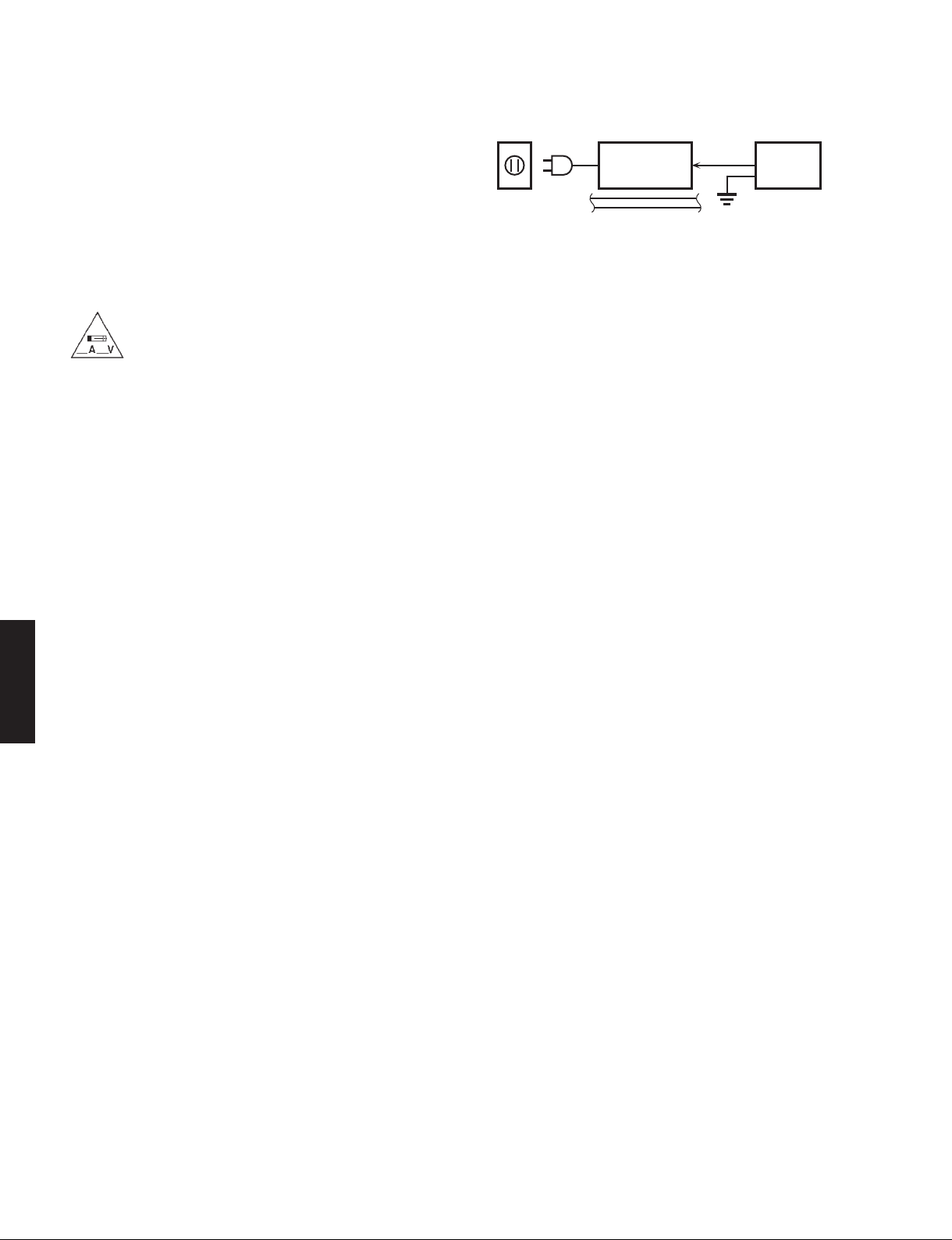
2. Leakage Current Measurement (For 120V Models Only)
When service has been completed, it is imperative to verify
that all exposed conductive surfaces are properly insulated
from supply circuits.
• Meter impedance should be equivalent to 1500 ohms shunted
by 0.15 μF.
WALL
OUTLET
• Leakage current must not exceed 0.5mA.
• Be sure to test for leakage with the AC plug in both polarities.
EQUIPMENT
UNDER TEST
INSULATING
TABLE
AC LEAKAGE
TESTER OR
EQUIVALENT
“CAUTION”
“F801: FOR CONTINUED PROTECTION AGAINST RISK OF FIRE, REPLACE ONLY WITH SAME TYPE 500mA,
250V FUSE.”
CAUTION
F801: REPLACE WITH SAME TYPE 500mA, 250V FUSE.
ATTENTION
F801: UTILISER UN FUSIBLE DE RECHANGE DE MÉME TYPE DE 500mA, 250V.
WARNING: CHEMICAL CONTENT NOTICE!
This product contains chemicals known to the State of California to cause cancer, or birth defects or other reproductive
harm.
DO NOT PLACE SOLDER, ELECTRICAL/ELECTRONIC OR PLASTIC COMPONENTS IN YOUR MOUTH FOR ANY REASON
WHATSOEVER!
Avoid prolonged, unprotected contact between solder and your skin! When soldering, do not inhale solder fumes or
expose eyes to solder/flux vapor!
If you come in contact with solder or components located inside the enclosure of this product, wash your hands before
handling food.
About lead free solder /
CD-S300
All of the P.C.B.s installed in this unit and solder joints are
soldered using the lead free solder.
Among some types of lead free solder currently available,
it is recommended to use one of the following types for
the repair work.
• Sn + Ag + Cu (tin + silver + copper)
• Sn + Cu (tin + copper)
• Sn + Zn + Bi (tin + zinc + bismuth)
Caution:
As the melting point temperature of the lead free solder
is about 30°C to 40°C (50°F to 70°F) higher than that of
無鉛ハンダについて
本機に搭載されているすべての基板およびハンダ付けに
よる接合部は無鉛ハンダでハンダ付けされています。
無鉛ハンダにはいくつかの種類がありますが、修理時に
は下記のような無鉛ハンダの使用を推奨します。
Sn+Ag+Cu(錫+銀+銅)
Sn+Cu(錫 + 銅)
Sn+Zn+Bi(錫 + 亜鉛 + ビスマス)
注意:
無鉛ハンダの融点温度は通常の鉛入りハンダに比べ 30 〜
40℃程度高くなっていますので、それぞれのハンダに合っ
たハンダごてをご使用ください。
the lead solder, be sure to use a soldering iron suitable
to each solder.
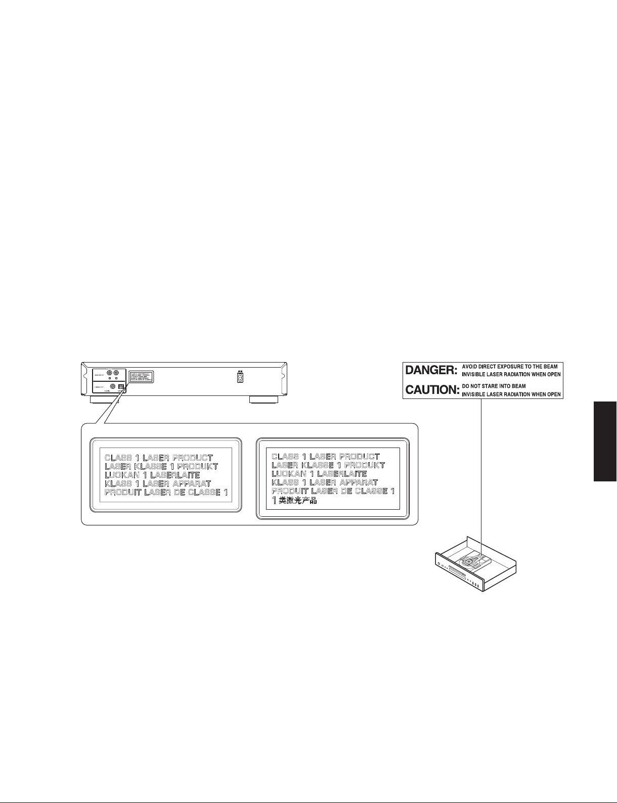
WARNING: Laser Safety
This product contains a laser beam component. This component may emit invisible, as well as visible radiation,
which may cause eye damage. To protect your eyes and skin from laser radiation, the following precautions must
be used during servicing of the unit.
1) When testing and/or repairing any component within the product, keep your eyes and skin more than 30 cm/1 feet
away from the laser pick-up unit at all times. Do not stare at the laser beam at any time.
2) Do not attempt to readjust, disassemble or repair the laser pick-up, unless noted elsewhere in this manual.
3) CAUTION: Use of controls, adjustments or performance of procedures other than those specified herein may result in
hazardous radiation exposure.
2
CD-S300
Laser Emitting conditions:
1) When the Top Cover is removed, and the STANDBY/ON SW is turned to the “ON” position, the laser component will
emit a beam for several seconds to detect if a disc is present. During this time (5-10 sec.) the laser may radiate
through the lens of the laser pick-up unit. Do not attempt any servicing during this period!
If no disc is detected, the laser will stop emitting the beam. When a disc is loaded, you will not be exposed to any
laser emissions.
2) The laser power level can be adjusted with the VR on the pick-up PWB, however, this level has been set by the factory
prior to shipping from the factory. Do not adjust this laser level control unless instruction is provided elsewhere in this
manual. Adjustment of this control can increase the laser emission level from the device.
Laser Diode Properties
Type: GaAlAs
Wavelength: 790 nm
Laser output: max. 1.23 μW *
* This output is the value measured at a distance of about 200 mm from the objective lens surface
on the Optical Pick-up Block.
R, A, G, L, J models T model
Warning for power supply
The primary side of the power supply carries live mains voltage when the player is connected to the mains even
when the player is switched off !
This primary area is not shielded so it is possible to accidentally touch copper tracks and/or components when servicing
the player.
Service personnel have to take precautions to prevent touching this area or components in this area.
Note:
The screws on the DVD mechanism may never be touched, removed or re-adjusted.
Handle the DVD mechanism with care when the unit has to be exchanged!
The DVD mechanism is very sensitive for dropping or giving shocks.
CD-S300
3
CD-S300
■ PREVENTION OF ELECTROSTATIC DISCHARGE
Some semiconductor (solid state) devices can be damaged easily by static electricity. Such components commonly are
called Electrostatically Sensitive (ES) Devices. Examples of typical ES devices are integrated circuits and some field-effect
transistors and semiconductor “chip” components. The following techniques should be used to help reduce the incidence
of component damage caused by electrostatic discharge (ESD).
1. Immediately before handling any semiconductor component or semiconductor-equipped assembly, drain off any ESD
on your body by touching a known earth ground. Alternatively, obtain and wear a commercially available discharging
ESD wrist strap, which should be removed for potential shock reasons prior to applying power to the unit under test.
2. After removing an electrical assembly equipped with ES devices, place the assembly on a conductive surface such as
aluminum foil, to prevent electrostatic charge buildup or exposure of the assembly.
3. Use only a grounded-tip soldering iron to solder or unsolder ES devices.
4. Use only an anti-static solder removal device. Some solder removal devices not classified as “anti-static (ESD
protected)” can generate electrical charge sufficient to damage ES devices.
5. Do not use freon-propelled chemicals. These can generate electrical charges sufficient to damage ES devices.
6. Do not remove a replacement ES device from its protective package until immediately before you are ready to install it.
(Most replacement ES devices are packaged with leads electrically shorted together by conductive foam, aluminum foil
or comparable conductive material).
7. Immediately before removing the protective material from the leads of a replacement ES device, touch the protective
material to the chassis or circuit assembly into which the device will be installed.
CAUTION: Be sure no power is applied to the chassis or circuit, and observe all other safety precautions.
8. Minimize bodily motions when handling unpackaged replacement ES devices. (Otherwise harmless motion such as
brushing together of your fabric clothes or lifting of your foot from a carpeted floor can generate static electricity (ESD)
sufficient to damage an ES device).
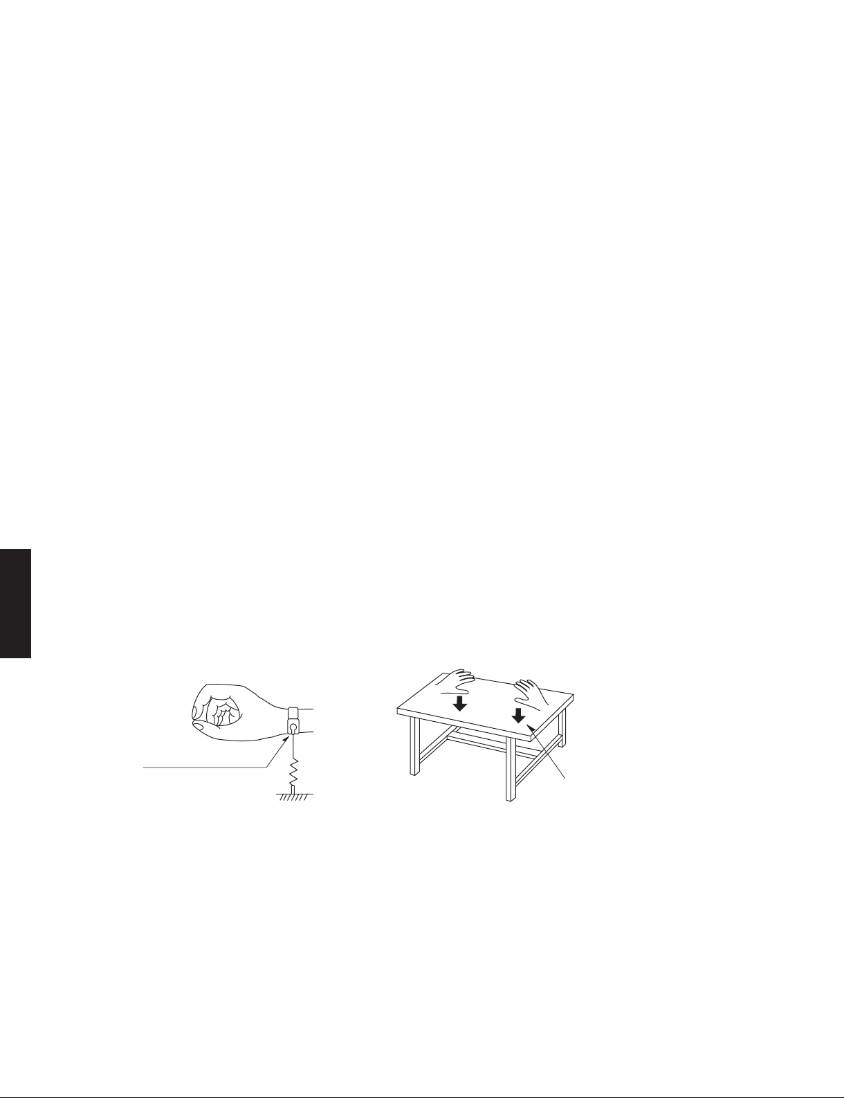
Grounding for electrostatic breakdown prevention
1. Human body grounding.
Use the antistatic wrist strap to discharge the static electricity from your body.
2. Work table grounding.
Put a conductive material (sheet) or steel sheet on the area where the optical pickup is placed and ground the sheet.
Caution:
The static electricity of your clothes will not be grounded through the wrist strap. So take care not to let your clothes touch
CD-S300
the optical pickup.
Anti-static wrist strap
1M-ohms
Conductive material
(sheet) or steel sheet
4
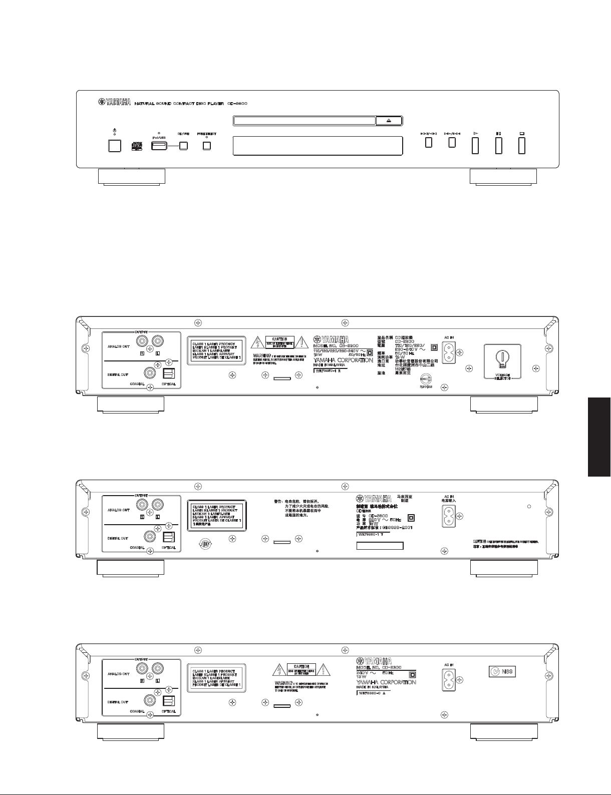
■ FRONT PANEL
R, T, A, G, L, J models
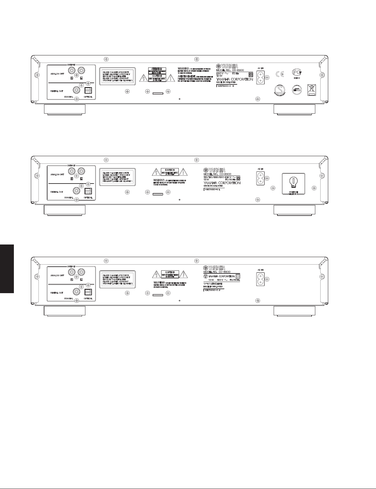
■ REAR PANELS
R model
CD-S300
T model
A model
CD-S300
5
CD-S300
G model
L model
J model
CD-S300
6
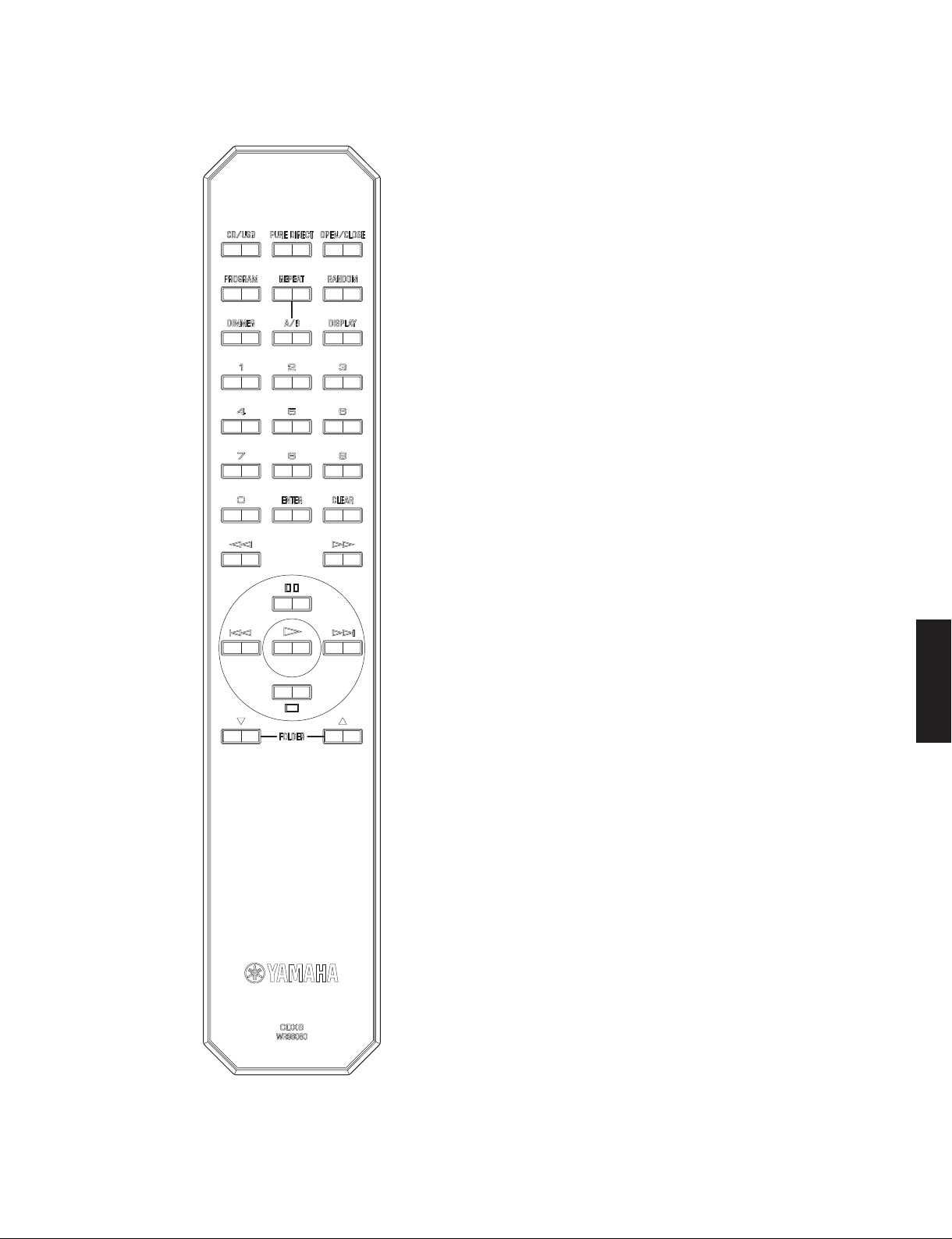
■ REMOTE CONTROL PANEL
CDX8
CD-S300
CD-S300
7
CD-S300
■ SPECIFICATIONS /
■ Audio Section /
Output Level /
..........................................................................................2.0 ±0.3 V
Signal to Noise Ratio /
................................................................................. 105 dB or more
Dynamic Range /
................................................................................... 96 dB or more
Total Harmonic Distortion / 歪率 (1 kHz)
..................................................................................0.003 % or less
Frequency Response /
............................................................................................. ±0.5 dB
Digital Output Terminal /
......................................................................................... Optical x 1
Other Output Terminal /
...................................................................................Analog out L/R
■ General /
Power Consumption /
.................................................................................................. 13 W
Power Supply /
R, L models ........................... AC 110/120/220/230–240 V, 50/60 Hz
T model ................................................................... AC 220 V, 50 Hz
A model .................................................................. AC 240 V, 50 Hz
G model .................................................................. AC 230 V, 50 Hz
J model .............................................................. AC 100 V, 50/60 Hz
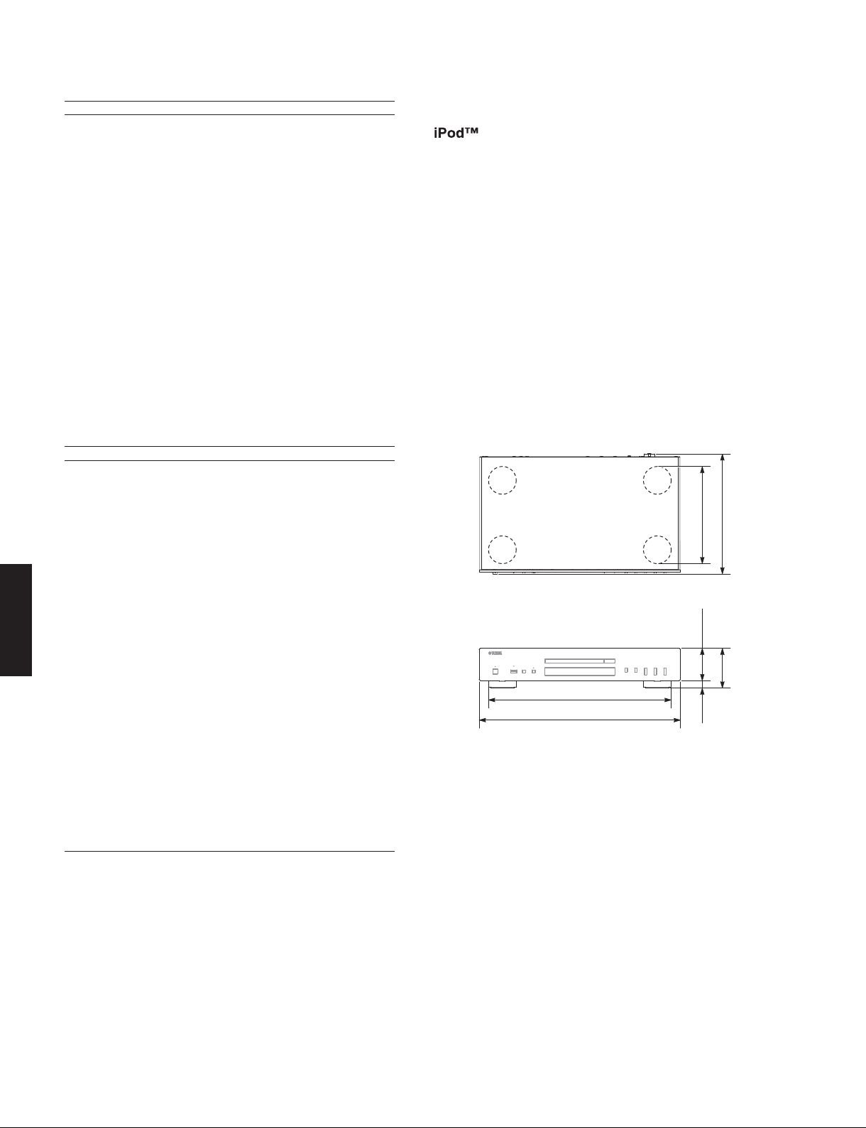
Dimensions (W x H x D) /
CD-S300
................................. 435 x 86 x 260 mm (17-1/8" x 3-3/8" x 10-1/4")
Weight / 質量
................................................................................. 3.5 kg (7.7 lbs.)
Finish /
仕上げ
Black color .....................................................R, T, A, G, L, J models
Silver color ......................................................R, T, A, G, L, J models
Accessories /
Remote control (CDX8) .................................................................x 1
Battery (R6, AA, UM-3) .................................................................x 2
Audio pin cable (1.0 m) ................................................................x 1
Power cable (1.5 m) .....................................................................x 1
オーディオ部
出力レベル
ダイナミックレンジ
総合
消費電力
電源電圧
付属品
信号対雑音比
周波数特性
参考仕様
(1 kHz, 0 dB)
(2 Hz to 20 kHz)
デジタル出力端子
その他の出力端子
寸法(幅×高さ×奥行き)
Coaxial x 1
USB
“iPod” is a trademark of Apple Inc., registered in U.S. and other countries.
“Made for iPod” means that an electronic accessory has been designed
to connect specifically to iPod and has been certified by the developer to
meet Apple performance standards.
Apple is not responsible for the operation of this device or its compliance
with safety and regulatory standards.
iPod は、米国およびその他の国々で登録された AppleComputer,Inc. の商
標または登録商標です。
「Madefor iPod」とは、iPod 専用に接続するよう設計され、アップルが定
める性能基準を満たしているとデベロッパーによって認定された電子アク
セサリーであることを示します。
アップルは、これらの機器操作または、安全規制基準に関する一切の責任
を負いません。
• DIMENSIONS /
寸法図
210 (8-1/4")16
260 (10-1/4")
70
(2-3/4")
86
395 (15-1/2")
435 (17-1/8")
(3-3/8")
(5/8")
Unit: mm (inch)
単位:mm(インチ)
* Specifications are subject to change without notice due to
product improvements.
※ 参考仕様および外観は予告なく変更されることがあります。
R ....................General model
T..................... Chinese model
A ................Australian model
G .................European model
L .................Singapore model
J ................... Japanese model
8
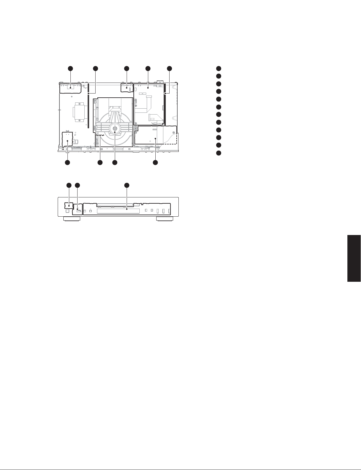
■ INTERNAL VIEW
CD-S300
25134
7698
1110 12
1
OPERATION (7) P.C.B. (R, L models)
2
OPERATION (5) P.C.B.
3
OPERATION (9) P.C.B.
4
MAIN P.C.B.
5
OPERATION (4) P.C.B.
6
OPERATION (6) P.C.B.
7
OPERATION (10) P.C.B.
8
Loader mechanism ass'y
9
OPERATION (8) P.C.B.
10
OPERATION (2) P.C.B.
11
OPERATION (3) P.C.B.
12
OPERATION (1) P.C.B.
CD-S300
9
CD-S300
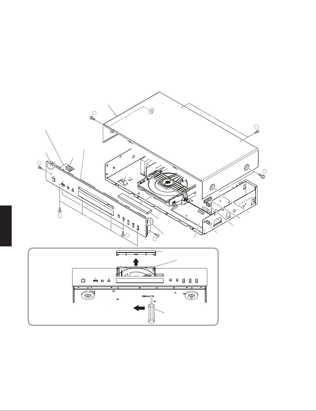
■ DISASSEMBLY PROCEDURES /
(Remove parts in the order as numbered.)
Disconnect the power cable from the AC outlet.
1. Removal of Top Cover
a. Remove 4 screws (①) and 2 screws (②). (Fig. 1)
b. Remove the top cover. (Fig. 1)
Top cover
トップ カ バ ー
1
OPERATION (6) P.C.B.
Hook
フック
3
Front panel ass'y
フロントパネルASSY
CB803
分解手順
(番号順に部品を取り外してください。)
AC 電源コンセントから、電源コードを抜いてください。
1. トップカバーの外し方
a. ①のネジ 4 本、②のネジ 2 本を外します。(Fig.1)
b. トップカバーを取り外します。(Fig.1)
2
1
4
CD-S300
How to manually eject the disc tray /
ディスクトレイを開ける方法
2. Removal of Front Panel Ass’y
a. Using a flatblade screwdriver, move the slider at the
bottom in the direction of the arrow shown above.
(Fig. 1)
Open the disc tray, remove the lid and close the disc
tray. (Fig. 1)
b. Remove 2 screws (③). (Fig. 1)
10
Lid
リッド
CB6
5
Hook
3
フック
Lid
リッド
Flatblade screwdriver
マイナスドライバー
CB807
OPERATION (8) P.C.B.
Disc tray
ディスクトレイ
MAIN P.C.B.
CB304
Fig. 1
2. フロントパネル ASSYの外し方
a. マイナスドライバーで底面のスライダーを上図の矢印
の方向に動かします。(Fig.1)
ディスクトレイを開けてリッドを取り外し、ディスク
トレイを閉じます。(Fig.1)
b. ③のネジ 2 本を外します。(Fig.1)
CD-S300
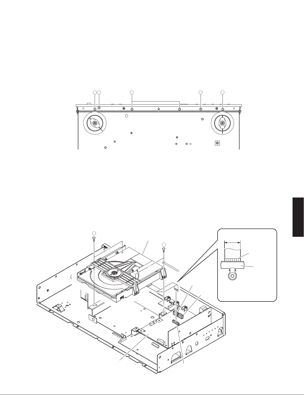
c. Remove 4 screws (④) and 2 screws (⑤). (Fig. 2)
d. Remove CB6, CB304, CB803 and CB807. (Fig. 1)
e. Release 2 hooks and then remove the front panel
ass’y. (Fig. 1)
Bottom view
4 4 45 5
3. Removal of Loader Mechanism Unit
a. Remove 4 screws (⑥). (Fig. 3)
b. Remove CB2 and CB3. (Fig. 3)
c. Remove CB4 and ground the terminal side of the
flexible flat cable with a clip or the like. (Fig. 3)
d. Remove the loader mechanism unit. (Fig. 3)
c. ④のネジ 4 本、⑤のネジ 1 本を外します。(Fig.2)
d. CB6、CB304、CB803、CB807を外します。(Fig.1)
e. フック 2箇所を外し、フロントパネル ASSYを取り外
します。(Fig.1)
Fig. 2
3. ローダーメカユニットの外し方
a. ⑥のネジ 4 本を外します。(Fig.3)
b. CB2、CB3 を外します。(Fig.3)
c. CB4 を外し、カード電線の端子面をクリップ等でアー
スします。(Fig.3)
d. ローダーメカユニットを取り外します。(Fig.3)
CD-S300
6
MAIN P.C.B.
Loader mechanism unit
ローダーメカユニット
6
CB4
CB3
CB2
17 mm
(0.67")
Terminal side
端子面
Clip
クリップ
Use a clip or other item to
ground the unit.
クリップ 等で ア ー ス してくだ さい 。
Fig. 3
11
CD-S300
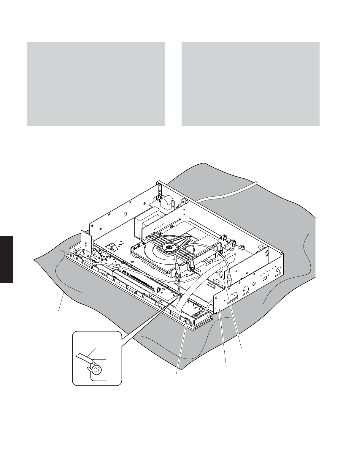
When checking the P.C.B.s:
• Spread the rubber sheet and the cloth. Then place
this unit on the cloth and check it. (Fig. 4)
• Connect the ground point (ST701) of the front panel
ass’y to the chassis with a ground lead or the like.
(Fig. 4)
• Reconnect all cables (connectors) that have been
disconnected.
• When connecting the flexible flat cable, be careful
with polarity.
P.C.B. をチェックする場合には:
・ ゴムシートと布を敷き、その上に本機を置いてチェッ
クします。(Fig.4)
・ フロントパネル ASSY のアース(ST701)をアース線等
でシャーシに接続してください。(Fig.4)
・ 外したケーブル(コネクター)をすべて接続します。
・ フラットケーブルを接続する際、極性に注意してく
ださい。
CD-S300
Rubber sheet and cloth
ゴ ム シ ートと布
Ground lead
アース線
Ground lead
アース線
ST701
Front panel ass'y
フロントパネルASSY
Fig. 4
Chassis
シャーシ
12
CD-S300
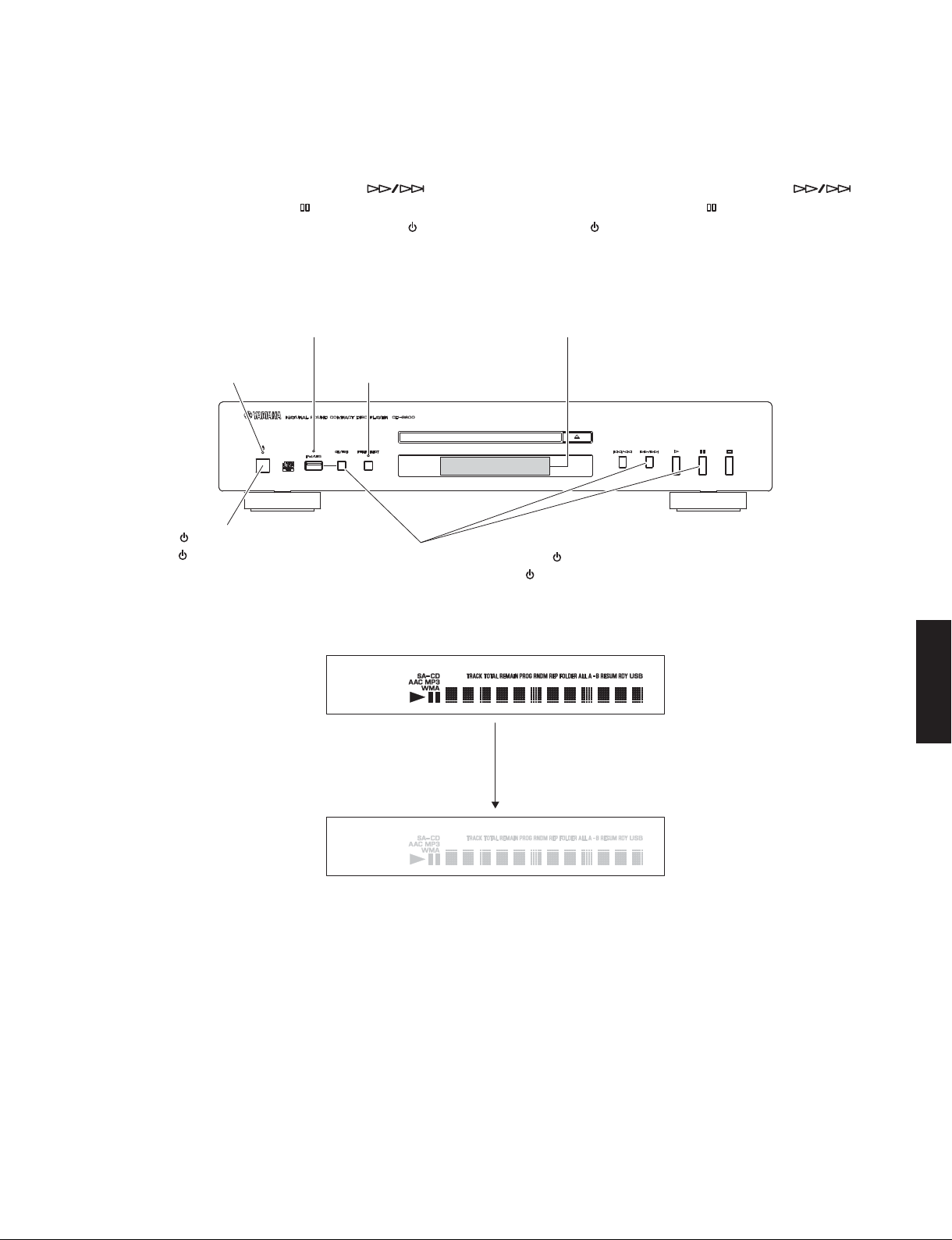
■ TEST MODE /
テストモード
● Starting test mode
When starting the test mode, check the FL display
and indicators for display/indication condition.
1. While pressing the “CD/USB”, “
Search forward) and “
as shown in the figure below, press the “
switch to turn on the power and keep pressing
those 3 keys.
iPod/USB indicator
iPod/USB インジケーター
Power indicator
電源インジケーター
" " (Power) switch
“”(電源)スイッチ
” (Pause) keys of this unit
PURE DIRECT indicator
PUREDIRECT インジケーター
While pressing these keys, press the “ ” (Power) switch to turn on the power.
これらのキーを押しながら、“”(電源)スイッチを押して電源を入れます。
” (Skip/
” (Power)
● テストモードの起動
テストモードの 起 動時 に、F L ディスプレイとインジケー
ターの表示 状態をチェックします。
1. 本機の下図に示す “CD/ USB” キー、“
出し/早送り) キ ー、“
ら“
”(電源)スイッチを押して電源を入れ、3 つの
キーを押し続けます。
FL display
FL ディスプレイ
”(ポーズ)キーを押しなが
”(頭
FL display /
2. While keep pressing those 3 keys, check that all
indicators (Power, iPod/USB, PURE DIRECT) are
lit.
At the same time, check that all segments of the
FL display are lit.
3. Release those 3 keys.
Then check that all indicators (Power, iPod/USB,
PURE DIRECT) as well as all segments of the FL
display are turned off.
FL ディスプレイ表示
CD-S300
All segments ON
全セグメント点灯
Release the keys
キーを離す
All segments OFF
全セグメント消灯
2. 3 つのキーを押したまま、全てのインジケーター
(電源、iPod/USB、PUREDIRECT)が点灯してい
ることを確認します。
同時に、FL ディスプレイの全セグメントが点灯し
ていることを確認します。
3. 3 つのキーを離します。
全てのインジケーター(電源、iPod/USB、PURE
DIRECT)と、FL ディスプレイの全セグメントが
消灯していることを確認します。
4. The Test Mode is activated.
4. テストモードが起動します。
13
CD-S300
● Operation Procedure of Test Mode
Function list of remote control keys /
Key /
キー
OPEN/CLOSE 79-01 Disc tray open/close /
1 79-11 Laser on /
2 79-12 Laser off /
3 79-13 Focus operation /
4 79-14
5 79-15 Traverse stop /
6 79-16
7 79-17
8 79-18 Spindle off /
9 79-19 Spindle on /
Key code /
キーコード
Traverse in
トラバース イン
Traverse out
トラバース アウト
Spindle reverse
スピンドル リバース
リモコンキーの機能一覧
レーザー オン
レーザー オフ
フォーカス動作
トラバース ストップ
スピンドル オフ
スピンドル オン
● テストモード時の操作
Function /
ディスクトレイ オープン/クローズ
* Press the “5” key to stop traverse.
※“5”キーを押してトラバースを停止してください。
* Press the “5” key to stop traverse.
※“5”キーを押してトラバースを停止してください。
* Press the “8” key to stop spindle.
※“8”キーを押してスピンドルを停止してください。
* Press the “8” key to stop spindle.
※“8”キーを押してスピンドルを停止してください。
機能
● Canceling Test Mode
CD-S300
Press the “ ” (Power) switch of this unit to turn off the
power.
● テストモードの解除
本機の “ ”(電源)スイッチを押して電源を切ります。
14
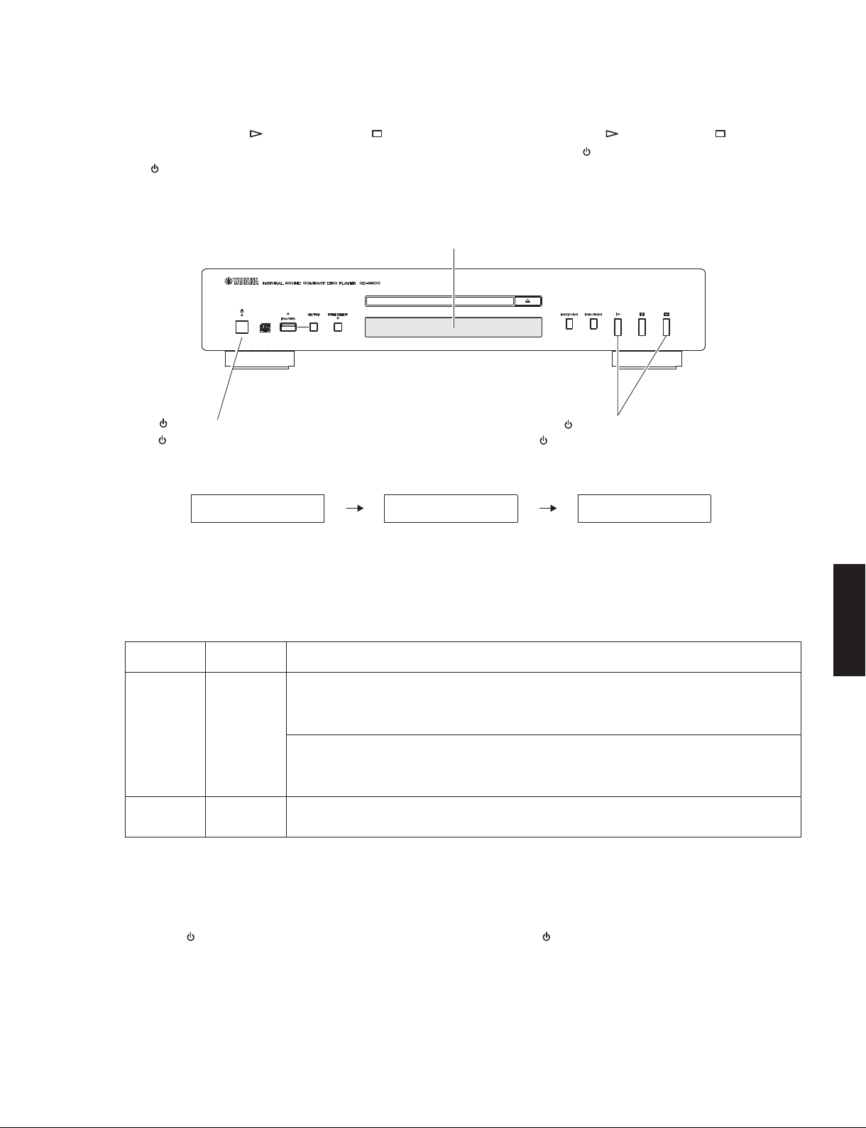
■ FACTORY MODE
● Starting Factory Mode
While pressing the “ ” (Play) and the “ ” (Stop)
keys of this unit as shown in the figure below, press
the “
” (Power) switch to turn on the power.
The Factory Mode is activated.
● ファクトリーモードの起動
FL display
FL ディスプレイ
CD-S300
本機の下図に示す “ ”(再生)キーと “ ”(停止)キー
を押しながら “
”(電源)スイッチを押して電源を入
れます。
ファクトリーモードが起動します。
" " (Power) switch
""(電源)スイッチ
Display provided when factory mode started /
● Operation Procedure of Factory Mode
Function list of remote control keys /
Key
キー
DISPLAY 79-0A
CLEAR 79-0D
Key code
キーコード
Firmware version of the microprocessor
(IC305 of the MAIN P.C.B.) is displayed.
マイコン(MAIN P.C.B.のIC305)のファーム
ウェアバージョンが表示されます。
Firmware version of the USB IC
(IC7 of the MAIN P.C.B.) is displayed.
USBIC(MAINP.C.B.のIC7)のファームウェア
バージョンが表示されます。
EEPROM (IC304 of the MAIN P.C.B.) is initialized.
EEPROM(MAINP.C.B.のIC304)を初期化します。
リモコンキーの機能一覧
While pressing these keys, press the “ ” (Power) switch to turn on the power.
これらのキーを押しながら、“”(電源)スイッチを押して電源を入れます。
ファクトリーモード起動時の表示
LOADINGFACTORY NODISC
● ファクトリーモード時の操作
Function
機能
* Press the “CD/USB” key to select the CD mode
※ “CD/USB”キーを押して、CDモードを選択し
てください。
* Press the “CD/USB” key to select the USB mode
※ “CD/USB”キーを押して、USBモードを選択し
てください。
CD-S300
● Canceling Factory Mode
Press the “ ” (Power) switch of this unit to turn off the
power.
● ファクトリーモードの起動
本機の “ ”(電源)スイッチを押して電源を切ります。
15

CD-S300
■ UPDATING FIRMWARE /
After replacing the following parts with the replacement
parts, update the latest firmware according to the
following procedure.
MAIN P.C.B.
Microprocessor (IC305) of MAIN P.C.B.
ファームウェアの書き込み
● Required tools
• Firmware downloader program
....................................................... FlashSta.exe
• Firmware
................................................... C5S3_xxxx.mot
C5S3_xxxx.id
• RS232C cross cable “D-sub 9 pin female”
(Specifications)
Pin No.2 RxD Pin No.2 RxD
Pin No.3 TxD Pin No.3 TxD
Pin No.5 GND Pin No.5 GND
Pin No.7 RTS Pin No.7 RTS
Pin No.8 CTS Pin No.8 CTS
• RS232C conversion adaptor (Part No.: WR492800)
下記の部品をサービス部品に交換した場合、下記の手順
により最新のファームウェアの書き込みを行ってくださ
い。
MAINP.C.B.
Microprocessor(IC305)ofMAINP.C.B.
● 必要なツール
・ ファームウェア書き込み用プログラム
............................................................................... FlashSta.exe
・ ファームウェア
.........................................................................C5S3xxxx.mot
C5S3xxxx.id
・ RS232C クロスケーブル “D-sub9pin メス”
(仕様)
Pin No.2 RxD Pin No.2 RxD
Pin No.3 TxD Pin No.3 TxD
Pin No.5 GND Pin No.5 GND
Pin No.7 RTS Pin No.7 RTS
Pin No.8 CTS Pin No.8 CTS
・ RS232C 変換アダプター(部品番号:WR492800)
● Preparation and precautions
• Download the firmware downloader program and
the latest firmware from the specified source to
the same folder of the PC.
CD-S300
• Prepare the above specified RS232C cross cable.
• While writing the firmware, keep the other application
software on the PC closed.
It is also recommended to keep the software on
the task tray closed as well.
● Confirmation of firmware version
Before and after updating the firmware, check the
firmware version by using the factory mode menu.
Start up the factory mode of this unit, and press the
“DISPLAY” key of the remote control. The firmware
version is displayed. (See “FACTORY MODE”)
Note down the displayed firmware version.
● 準備と注意
・ 指定のダウンロード先から、ファームウェア書き
込み用プログラムと最新のファームウェアを、PC
の同じフォルダにダウンロードしてください。
・ RS232C クロスケーブルは必ず上記仕様のものを
用意してください。
・ 書き込み時は、PC 上の他のアプリケーションソ
フトは閉じてください。
さらに、タスクトレイ上にあるソフトも閉じてお
くことを推奨します。
● ファームウェアバージョンの確認
ファームウエアの書き込みの前後に、ファームウエ
アのバージョンをファクトリーモードで確認します。
本機のファクトリーモードを起動し、リモコンの
“DISPLAY” キーを押すとファームウェアバージョンが
表示されます。(「ファクトリーモード」参照)
表示されたファームウェアバージョンを書き留めま
す。
16
OPE:v1.09
Firmware version
CD-S300
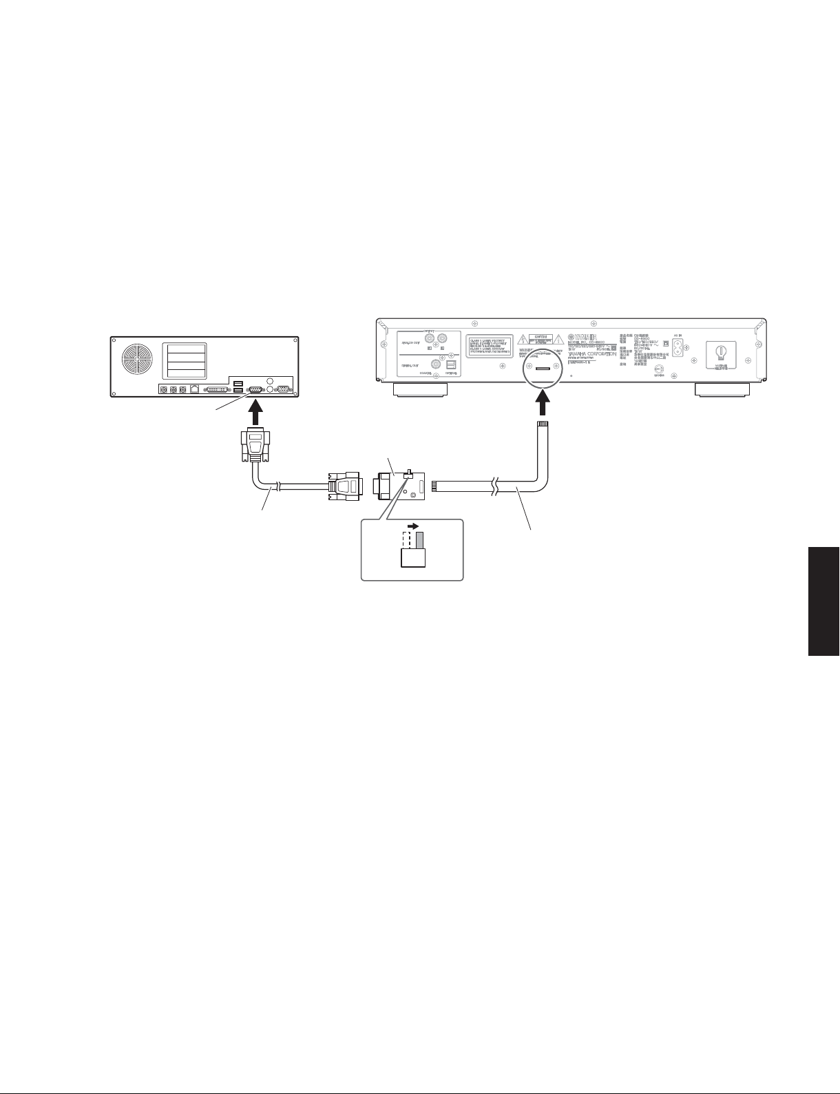
● Connection
1. Set the switch (SW7) of RS232C conversion
adaptor to the “FLASH UCOM” position. (Fig. 1)
2. Connect the writing port (CB902 of OPERATION
P.C.B.) located on the rear panel of this unit to the
serial port (RS232C) of the PC with RS232C cross
cable, RS232C conversion adaptor and flexible
flat cable as shown below. (Fig. 1)
PC
Serial port (RS232C)
RS232C conversion adaptor
RS232C変換アダプター
● 接続
1. RS232C変換アダプターのスイッチ(SW7)“FLASH
UCOM” 側に設定します。(Fig.1)
2. 本機の書き込み用ポート(OPERATIONP.C.B. の
CB902) と PC のシリアルポート(RS232C)を下記
のように接続します。(Fig.1)
This unit
RS232C cross cable
RS232Cクロスケーブル
OTHER
SW7
FLASH
UCOM
Fig. 1
Flexible flat cable (9P)
カード電線(9P)
CD-S300
17
CD-S300
● Operation procedures
1. Connect the power cable of this unit to the AC
outlet.
2. Press the “
the power.
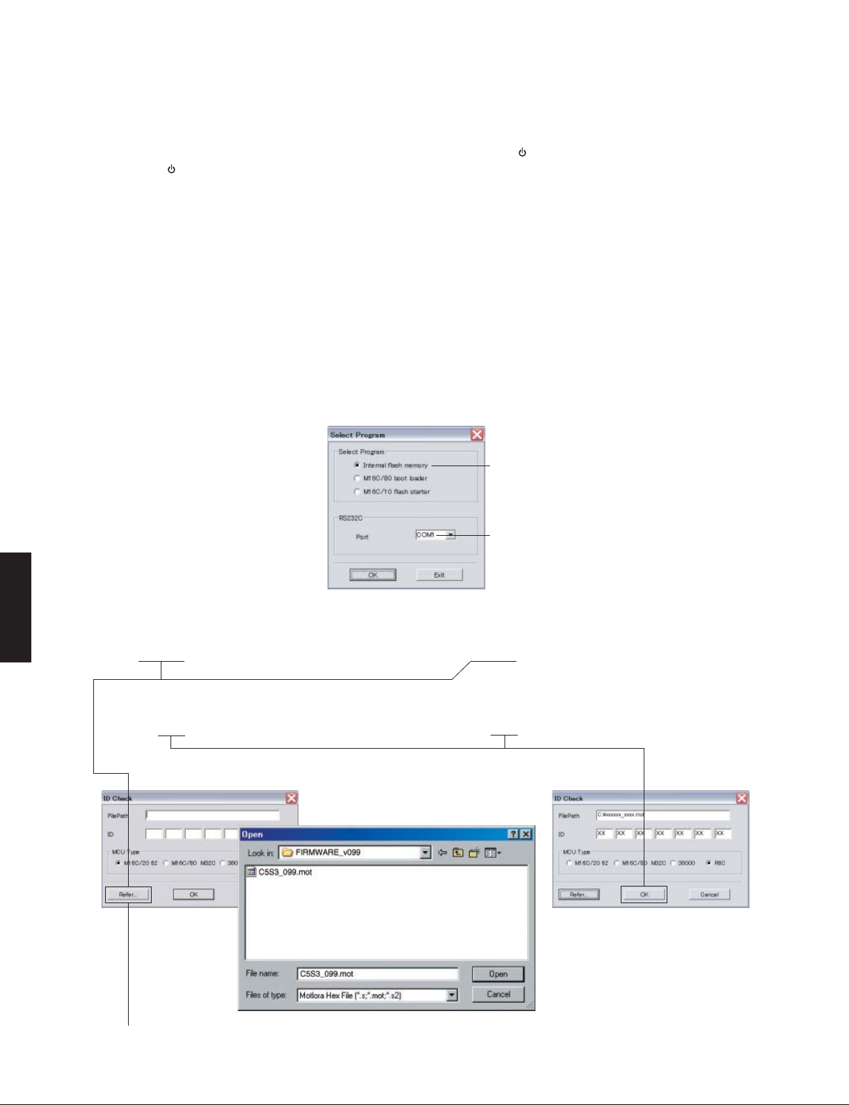
3. Start up FlashSta.exe. (Fig. 2)
The screen appears as shown below. (Fig. 2)
4. Select the data to be transmitted and port. (Fig. 2)
• Select Program
Select Internal flash memory.
• RS232C
Select the port of RS-232C
* For selection of the port, COM1 to 4 can
” (Power) switch of this unit to turn on
be used.
As COM5 or higher port cannot be used,
select out of COM 1 to 4 of the setting on
the PC side.
● 操作方法
1. 本機の電源コードを AC コンセントに接続します。
2. 本機の “
ます。
3. FlashSta.exe を起動します。(Fig.2)
下記の画面が表示されます。(Fig.2)
4. 送信データ、ポートを選択します。(Fig.2)
・ SelectProgram
・ RS232C
”(電源)スイッチを押して電源を入れ
Internalflashmemory を選択します。
接続している RS-232 Cポートを選択します。
※ ポートの選択は COM1 〜 4 までが使用で
きます。
COM5 以上は使用できませんので、PC 側
の設定で COM1 〜 4 を選択してください。
Select Internal flash memory
Internalflashmemory を選択します
Select the port of RS-232C
接続している RS-232C ポートを選択します
Fig. 2
CD-S300
5. Click [Refer...] and select the firmware name.
(Fig. 3)
* The ID and MCU Type are loaded automatically
when the file is selected. (Fig. 3)
Click [OK]. (Fig. 3)
5.[Refer...]をクリックし、書き込むファームウェア
を選択します。(Fig.3)
※ ID、および MCUType は書き込みファイル選
択後、自動的に取り込まれます。(Fig.3)
[OK]をクリックします
When [Refer...] is clicked, the “Open” screen appears.
[Refer...]をクリックすると「ファイルを開く」が表示されます
18
Fig. 3