

Page 1

Integrated Amplifier
Amplificateur Intégré
Integrated Amplifier
G
G
Amplificateur Intégré
ИНСТРУКЦИЯ ПО ЭКСПЛУАТАЦИИ
OWNER’S MANUAL
OWNER’S MANUAL
MODE D’EMPLOI
MODE D’EMPLOI
BEDIENUNGSANLEITUNG
BEDIENUNGSANLEITUNG
BRUKSANVISNING
BRUKSANVISNING
MANUALE DI ISTRUZIONI
MANUALE DI ISTRUZIONI
MANUAL DE INSTRUCCIONES
MANUAL DE INSTRUCCIONES
GEBRUIKSAANWIJZING
GEBRUIKSAANWIJZING
Page 2
CAUTION: READ THIS BEFORE OPERATING YOUR UNIT.
CAUTION: READ THIS BEFORE OPERATING YOUR UNIT.
1 To assure the finest performance, please read this manual
carefully. Keep it in a safe place for future reference.
2 Install this sound system in a well ventilated, cool, dry,
clean place - away from direct sunlight, heat sources,
vibration, dust, moisture, and/or cold. For proper
ventilation, allow the following minimum clearances
around this unit.
Top: 30 cm
Rear: 20 cm
Sides: 20 cm
3 Locate this unit away from other electrical appliances,
motors, or transformers to avoid humming sounds.
4 Do not expose this unit to sudden temperature changes
from cold to hot, and do not locate this unit in an
environment with high humidity (i.e. a room with a
humidifier) to prevent condensation inside this unit,
which may cause an electrical shock, fire, damage to this
unit, and/or personal injury.
5 Avoid installing this unit where foreign object may fall
onto this unit and/or this unit may be exposed to liquid
dripping or splashing. On the top of this unit, do not
place:
– Other components, as they may cause damage and/or
discoloration on the surface of this unit.
– Burning objects (i.e. candles), as they may cause fire,
damage to this unit, and/or personal injury.
– Containers with liquid in them, as they may fall and
liquid may cause electrical shock to the user and/or
damage to this unit.
6 Do not cover this unit with a newspaper, tablecloth,
curtain, etc. in order not to obstruct heat radiation. If the
temperature inside this unit rises, it may cause fire,
damage to this unit, and/or personal injury.
7 Do not plug in this unit to an AC wall outlet until all
connections are complete.
8 Do not operate this unit upside-down. It may overheat,
possibly causing damage.
9 Do not use force on switches, knobs and/or cords.
10 When disconnecting the power cable from the AC wall
outlet, grasp the plug; do not pull the cable.
11 Do not clean this unit with chemical solvents; this might
damage the finish. Use a clean, dry cloth.
12 Only voltage specified on this unit must be used. Using
this unit with a higher voltage than specified is dangerous
and may cause fire, damage to this unit, and/or personal
injury. Yamaha will not be held responsible for any
damage resulting from use of this unit with a voltage
other than specified.
13 To prevent damage by lightning, keep the power cable
and outdoor antennas disconnected from an AC wall
outlet or this unit during a lightning storm.
14 Do not attempt to modify or fix this unit. Contact
qualified Yamaha service personnel when any service is
needed. The cabinet should never be opened for any
reasons.
15 When not planning to use this unit for long periods of
time (i.e. vacation), disconnect the AC power plug from
the AC wall outlet.
16 Be sure to read the “TROUBLESHOOTING” section on
common operating errors before concluding that this unit
is faulty.
17 Before moving this unit, press A (power) to set this unit
to standby mode, and then disconnect the AC power plug
from the AC wall outlet.
18 Condensation will form when the surrounding
temperature changes suddenly. Disconnect the power
cable from the outlet, then leave this unit alone.
19 When using this unit for a long time, this unit may
become warm. Turn the power off, then leave this unit
alone for cooling.
20 Install this unit near the AC wall outlet and where the AC
power plug can be reached easily.
21 The batteries shall not be exposed to excessive heat such
as sunshine, fire or the like.
22 Excessive sound pressure from earphones and
headphones can cause hearing loss.
This unit is not disconnected from the AC power source as long as
it is connected to the AC wall outlet, even if this unit itself is turned
off by A. This state is called the standby mode. In this state, this
unit is designed to consume a very small quantity of power.
WARNING
TO REDUCE THE RISK OF FIRE OR ELECTRIC SHOCK, DO
NOT EXPOSE THIS UNIT TO RAIN OR MOISTURE.
This label is required to be attached to a product of which
the temperature of the top cover may be hot during
operation.
■ For U.K. customers
If the socket outlets in the home are not suitable for the
plug supplied with this appliance, it should be cut off and
an appropriate 3 pin plug fitted. For details, refer to the
instructions described below.
Note
The plug severed from the mains lead must be destroyed,
as a plug with bared flexible cord is hazardous if engaged
in a live socket outlet.
■ Special Instructions for U.K. Model
IMPORTANT
THE WIRES IN MAINS LEAD ARE COLOURED IN
ACCORDANCE WITH THE FOLLOWING CODE:
Blue: NEUTRAL
Brown: LIVE
As the colours of the wires in the mains lead of this apparatus may
not correspond with the coloured markings identifying the
terminals in your plug, proceed as follows:
The wire which is coloured BLUE must be connected to the
terminal which is marked with the letter N or coloured BLACK.
The wire which is coloured BROWN must be connected to the
terminal which is marked with the letter L or coloured RED.
Make sure that neither core is connected to the earth terminal of the
three pin plug.
i En
Page 3
CONTENTS
USEFUL FEATURES ................................... 1
SUPPLIED ACCESSORIES......................... 1
CONTROLS AND FUNCTIONS................. 2
PLAYBACK................................................. 11
Playing a source ............................................. 11
Adjusting to the desired sound....................... 12
Front panel ........................................................2
Rear panel .........................................................4
Remote control..................................................6
TROUBLESHOOTING.............................. 13
SPECIFICATIONS ..................................... 15
CONNECTIONS............................................9
Connecting speakers and source components...9
Connecting power cable..................................10
About this manual
• y indicates a tip for your operation.
• The illustrations used in this Owner’s Manual are A-S701.
• Depending on the model, there are some countries/regions where it may not be sold.
USEFUL FEATURES
This unit allows you to:
◆ Enjoy the highest sound quality of compact discs by
using the CD direct function (A-S701 only)
(see page 12)
◆ Enjoy pure, high fidelity sound by using the Pure
Direct function (see page 12)
◆ Save power by using AUTO POWER STANDBY
switch (see page 4)
◆ Use the remote control of this unit to operate a Yamaha
tuner and/or CD player (see page 7)
◆ Boost bass sounds by connecting a subwoofer
(see page 9)
English
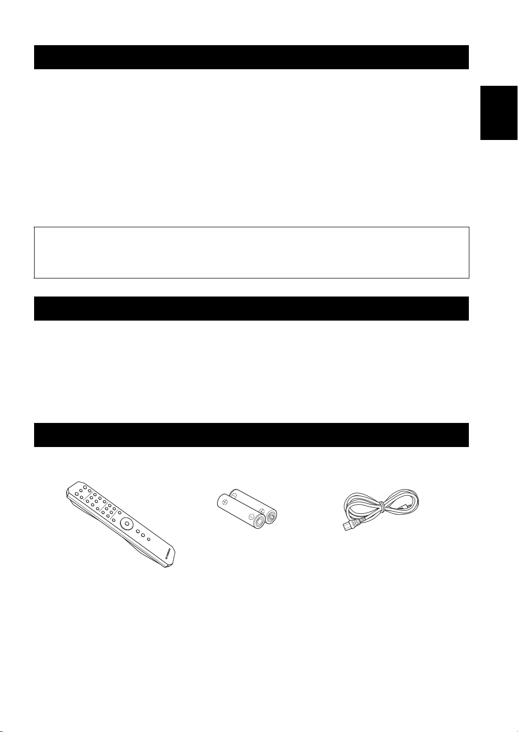
SUPPLIED ACCESSORIES
Please check that you received all of the following parts.
Remote control Batteries (x2)
(AA, R6, UM-3)
Power cable
(A-S701 only)
1 En
Page 4
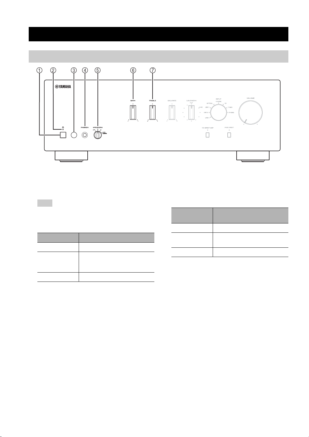
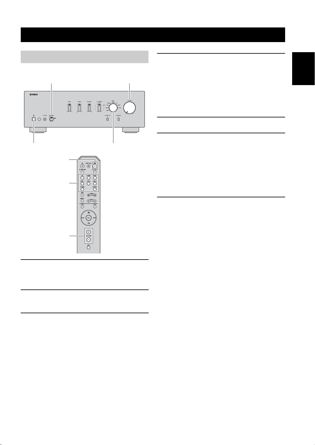
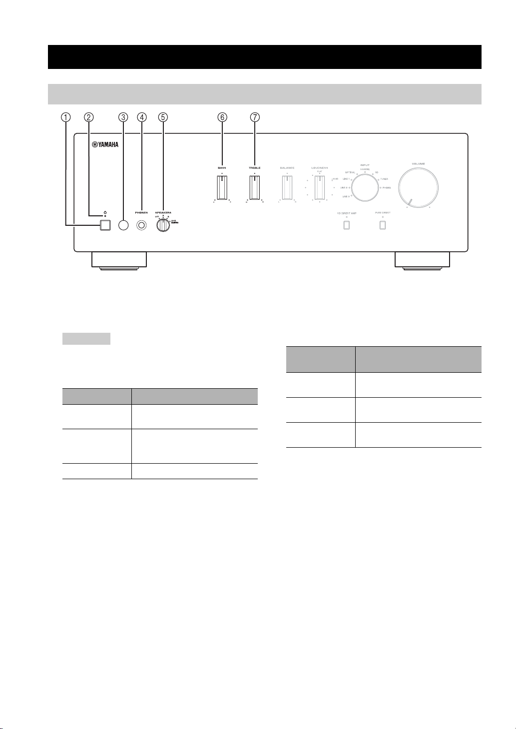
Front panel
CONTROLS AND FUNCTIONS
(A-S701)
1 A (power) switch
Turns on and off the power of this unit.
Note
Even when this unit is turned off, this unit consumes a small
amount of power.
2 Power indicator
Indicator Status
Brightly lit The power of this unit is “on”.
Dimly lit
Off The power of this unit is “off”.
This unit is in “standby” mode.
For details on the “standby” mode, see
page 6.
3 Remote control sensor
Receives infrared signals from the remote control.
4 PHONES jack
Connect your headphones.
5 SPEAKERS selector
Selector
position
OFF Both sets of speakers are off.
A or B
A+B BI-WIRING Both sets of speakers are on.
Speaker status
The set of speakers connected to the A
or B terminals is on.
6 BASS control
Increases or decreases the low frequency response.
The 0 position produces a flat response.
Control range: –10 dB to +10 dB
7 TREBLE control
Increases or decreases the high frequency response.
The 0 position produces a flat response.
Control range: –10 dB to +10 dB
2 En
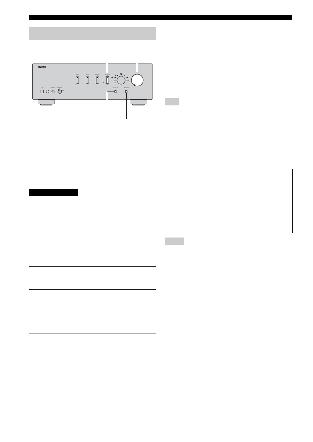
Page 5

CONTROLS AND FUNCTIONS
(A-S701)
English
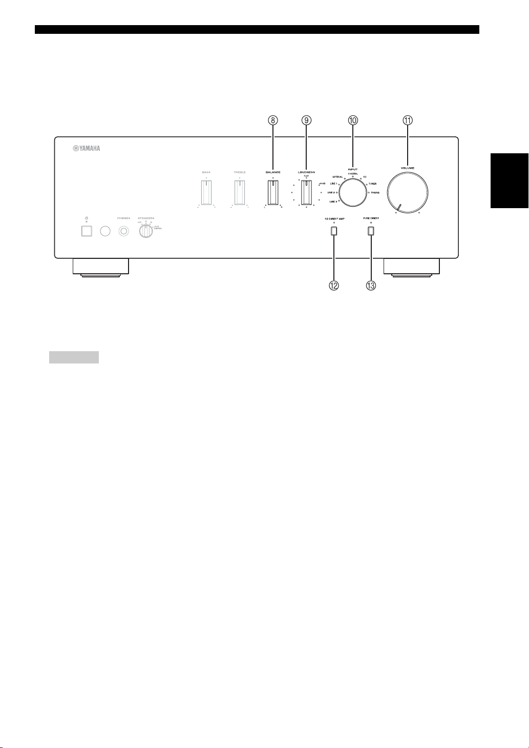
8 BALANCE control
Adjusts the sound output balance of the left and right
speakers to compensate for sound imbalances.
Note
If you rotate the BALANCE control to the end of L (left) or
R (right), the opposite side of channel is muted.
9 LOUDNESS control
Retain a full tonal range at any volume level
(see page 12).
0 INPUT selector and indicators
Selects the input source you want to listen to. The
input source indicators light up when the
corresponding input sources are selected.
y
The input source names correspond to the names of the
connection jacks on the rear panel.
A VOLUME control
Increases or decreases the sound output level.
B CD DIRECT AMP button and indicator
(A-S701 only)
Reproduces CD sound in the highest signal quality
(see page 12).
The indicator above it lights up when this function is
turned on.
C PURE DIRECT button and indicator
Reproduces any input source in the purest sound
possible (see page 12).
The indicator above it lights up when this function is
turned on.
3 En
Page 6
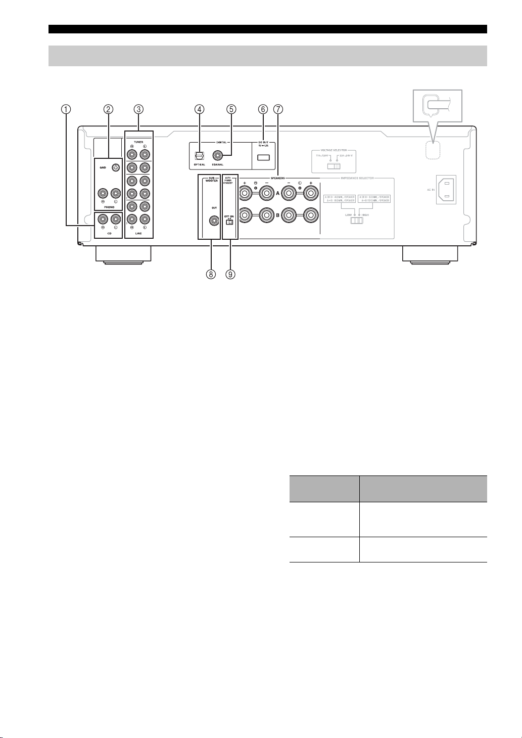
CONTROLS AND FUNCTIONS
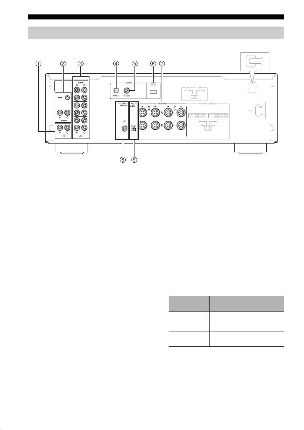
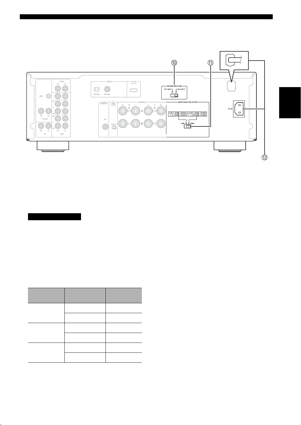
Rear panel
(A-S501/S301)
(A-S701)
1 CD input jacks
Used to connect a CD player (see page 9).
2 PHONO jacks and GND terminal
Used to connect a turntable that uses an MM cartridge,
and to ground the terminal (see page 9).
3 Audio input/output jacks
Used to connect external components, such as a tuner,
etc (see page 9).
4 DIGITAL (OPTICAL) jack
Used to connect a component with a digital optical
output (see page 9).
5 DIGITAL (COAXIAL) jack
Used to connect a component with a digital coaxial
output (see page 9).
6 DC OUT jack
For supplying power to a Yamaha AV accessory. For
details on connections, refer to the instruction manual
of the AV accessory.
7 SPEAKERS A/B terminals
Used to connect one or two speaker sets (see page 9).
8 SUBWOOFER OUT jack
Used to connect a subwoofer with built-in amplifier
(see page 9).
y
The SUBWOOFER OUT jack attenuates signals over 90 Hz.
9 AUTO POWER STANDBY switch
ON
OFF
Switch
position
The unit enters standby mode
automatically if not operated for 8
hours.
The unit does not enter standby mode
automatically.
Status
4 En
Page 7
CONTROLS AND FUNCTIONS
(A-S501/S301)
(A-S701)
English
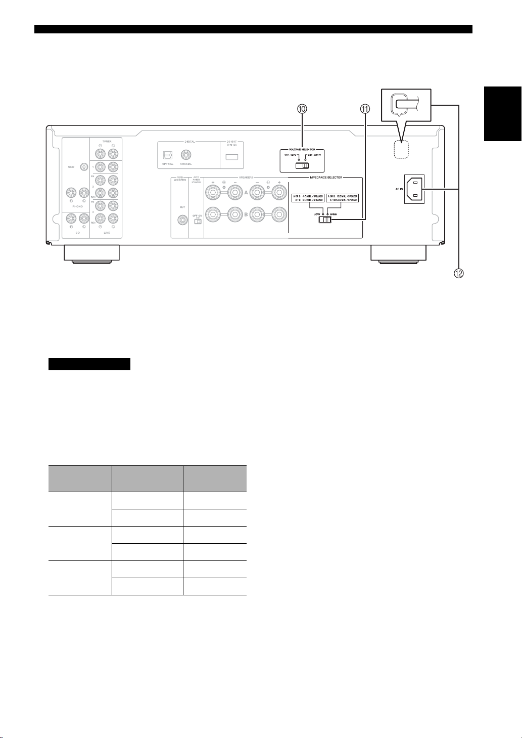
0 VOLTAGE SELECTOR (General model only)
Used to set to your local main voltage (see page 10).
A IMPEDANCE SELECTOR switch
CAUTION
Do not change the IMPEDANCE SELECTOR switch
while the power is turned on, as doing so may damage
the unit.
If the IMPEDANCE SELECTOR switch may not be
fully slid to either position, remove the power cable
and slide the switch all the way to either position.
Select the switch position according to the impedance
of the speakers.
Speaker
connection
SPEAKERS A
or
SPEAKERS B
SPEAKERS A
and
SPEAKERS B
Bi-wiring
Speaker
impedance
6 Ω or higher HIGH
4 Ω or higher LOW
12 Ω or higher HIGH
8 Ω or higher LOW
6 Ω or higher HIGH
4Ω or higher LOW
position
Switch
B AC IN (A-S701)
Used to connect the supplied power cable to an AC
wall outlet (see page 10).
Power cable (A-S501/S301)
Used to connect this unit to an AC wall outlet
(see page 10).
5 En
Page 8
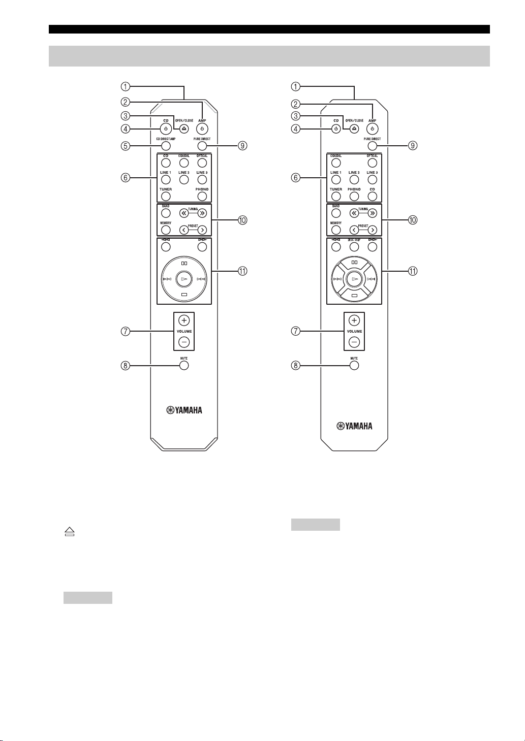
CONTROLS AND FUNCTIONS
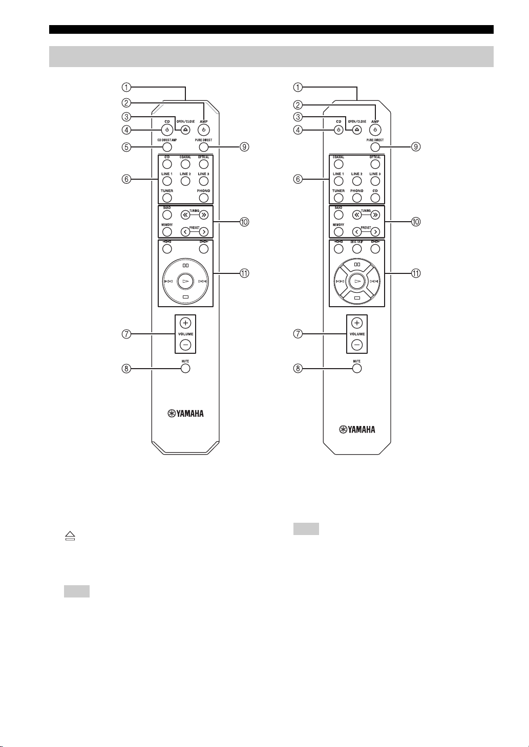
Remote control
1 Infrared signal transmitter
Sends infrared signals.
2 A AMP
Turns this unit on, or sets it to standby mode.
3 OPEN/CLOSE
Opens/closes the disc tray of the Yamaha CD player.
Refer to the owner’s manual of your CD player for
details.
Note
Even when using a Yamaha CD player, certain components
and features may not be available.
6 En
(A-S501/S301)(A-S701)
4 A CD
Turns the Yamaha CD player on, or sets it to standby
mode. Refer to the owner’s manual of your CD player
for details.
Note
Even when using a Yamaha CD player, certain components
and features may not be available.
5 CD DIRECT AMP (A-S701 only)
Reproduces CD sound in the highest signal quality
(see page 12).
6 Input selector buttons
Selects the input source you want to listen to.
y
The input source names correspond to the names of the
connection jacks on the rear panel.
Page 9

CONTROLS AND FUNCTIONS
7 VOLUME +/–
Increases or decreases the sound output level.
8 MUTE
Reduces the current volume level by approximately
20 dB. Press again to restore the audio output to the
previous volume level. Pressing the VOLUME +/–
also cancels muting.
The input indicator on the front panel for the current
input source blinks while the output is muted.
9 PURE DIRECT
Reproduces any input source in the purest sound
possible (see page 12).
0 Yamaha tuner control buttons
The following buttons can be used to control various
functions of a Yamaha tuner.
Refer to your component’s owner’s manual for more
information.
BAND
Selects the reception band (FM/AM).
TUNING jj / ii
Selects the tuning frequency.
MEMORY
Stores the current FM/AM station as a preset.
PRESET j / i
Selects a preset FM/AM station.
A Yamaha CD player control buttons
The following buttons can be used to control a
Yamaha CD player.
Refer to your component’s owner’s manual for more
information.
w Rewinds playback
f Fast-forwards playback
DISC SKIP Skips to the next disc in a CD changer
(A-S501/S301 only)
e Pauses playback
b Skips backward
a Skips forward
p Starts playback
s Stops playback
Note
Even when using a Yamaha CD player, certain components
and features may not be available.
English
Note
Even when using a Yamaha tuner, certain components and
features may not be available.
7 En
Page 10
CONTROLS AND FUNCTIONS
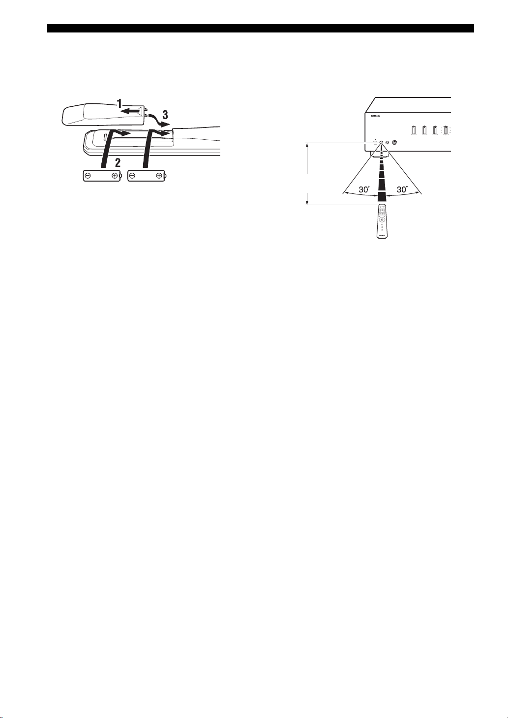
■ Installing batteries ■ Operation range
Point the remote control at the remote control sensor on
this unit and remain within the operating range shown
below.
Approximately
AA, R6, UM-3 batteries
■ Notes on remote control and batteries
• The area between the remote control and this unit must be clear of large obstacles.
• Be careful not to spill water or other liquids on the remote control.
• Be careful not to drop the remote control.
• Do not leave or store the remote control in the following conditions:
– places of high humidity, such as near a bathroom
– places of high temperatures, such as near a heater or stove
– places of extremely low temperatures
– dusty places
• Change all batteries if you notice the operation range of the remote control narrows.
• If the batteries run out, immediately remove them from the remote control to prevent an explosion or acid leak.
• If you find leaking batteries, discard the batteries immediately, taking care not to touch the leaked material. If the leaked material
comes into contact with your skin or gets into your eyes or mouth, rinse it away immediately and consult a doctor. Clean the battery
compartment thoroughly before installing new batteries.
• Do not use old batteries together with new ones. This may shorten the life of the new batteries or cause old batteries to leak.
• Do not use different types of batteries (such as alkaline and manganese batteries) together. Batteries that look the same may have a
different specification.
• Dispose of batteries according to your regional regulations.
• Keep the batteries in a location out of reach of children.
Batteries can be dangerous if a child were to put in his or her mouth.
• If you plan not to use this unit for a long period of time, remove the batteries from this unit. Otherwise, the batteries will wear out,
possibly resulting in a leakage of battery liquid that may damage this unit.
6 m
Remote control
8 En
Page 11
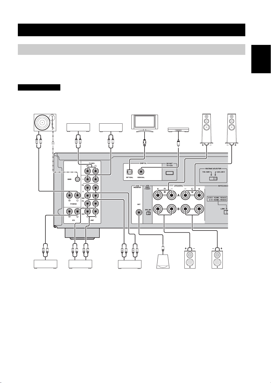
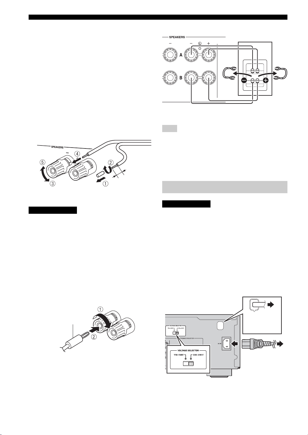
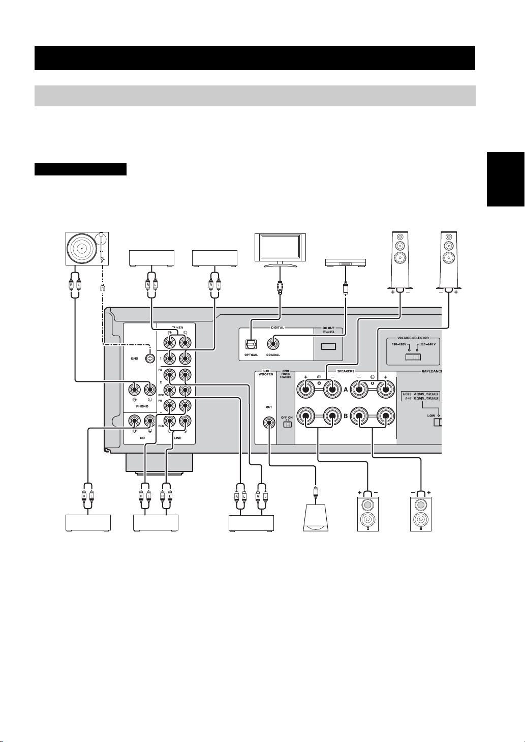
CONNECTIONS
Connecting speakers and source components
Make sure to connect L (left) to L, R (right) to R, “+” to “+” and “–” to “–”. If the connections are faulty, no sound will
be heard from the speakers, and if the polarity of the speaker connections is incorrect, the sound will be unnatural and
lack bass. Refer to the owner’s manual for each of your components.
Make sure to use RCA cables or optical cable to connect audio components.
CAUTION
Do not connect this unit or other components to the main power until all connections between components are complete.
Speakers A
LeftRight
Audio
out
Turntable
GND
Audio
out
Tuner
DVD player,
etc.
Audio
out
TV, etc.
Audio
out
BD player, etc.
Audio
out
English
Audio
out
CD player
Only PCM signals can be input to the DIGITAL (OPTICAL/COAXIAL) jacks of this unit. For details on the supported
PCM signals, see page 15.
Audio
out
Audio
In
etc.
Audio
In
CD recorder,
etc.
Audio
out
SubwooferTape deck,
Speakers B
LeftRight
y
• The PHONO jacks are designed for connecting a turntable with an MM cartridge.
• Connect your turntable to the GND terminal to reduce noise in the signal. However, for some turntables, you may hear less noise
without the GND connection.
9 En
Page 12
CONNECTIONS
■ REC jacks
• The audio signals are not output via the LINE 2 REC
or LINE 3 REC output jacks when LINE 2 or LINE 3
is selected with the INPUT selector.
• The VOLUME, BASS, TREBLE, BALANCE and
LOUDNESS controls and the CD DIRECT function
(or the PURE DIRECT function) have no effect on the
source being recorded.
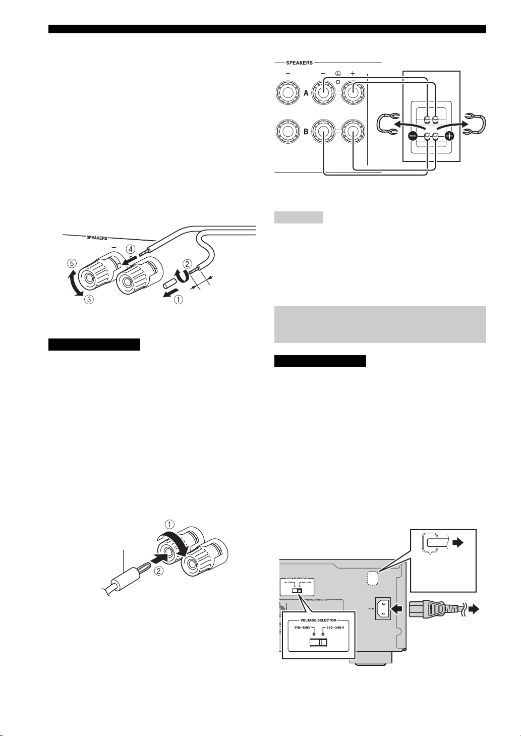
■ Connecting speaker cables
1 Remove approximately 10 mm of insulation from the
end of each speaker cable.
2 Twist the bare wires of the cable firmly together.
3 Unscrew the knob.
4 Insert one bare wire into the hole in the side of each
terminal.
5 Tighten the knob to secure the wire.
10 mm
Red: positive (+)
Black: negative (–)
CAUTION
• Set the IMPEDANCE SELECTOR switch according to
the impedance of the speakers to be connected (see
page 5).
• Do not let bare speaker wires touch each other or any
metal part of this unit. This could damage this unit and/
or the speakers.
■ Connecting via banana plug
(North America, General, China and
Australia models only)
1 Tighten the knob.
2 Insert the banana plug into the end of the
corresponding terminal.
Rear panel
Speaker
Connect the other speaker to the other set of terminals in
the same way.
Note
When making bi-wire connections, remove the shorting bridges
or cables on the speaker. Refer to the speakers’ instruction
manuals for more information.
y
To use the bi-wire connections, set the SPEAKERS selector on
the front panel to the A+B BI-WIRING position.
Connecting power cable
CAUTION
(General model only)
Before connecting the power cable, make sure you set
VOLTAGE SELECTOR of this unit according to your
local voltage. Improper setting of VOLTAGE SELECTOR
may cause fire and damage to this unit.
■ AC IN (A-S701)
Connect the supplied power cable to AC IN after all other
connections are complete.
■ Power cable (A-S501/S301)
Connect the power cable to an AC wall outlet after all
other connections are complete.
Banana plug
■ Bi-wire connection
In the case of speakers supporting the bi-wiring
connection, the tweeter/midrange unit and woofer of the
speakers can be driven independently through connections
shown in the following figure, allowing you to enjoy clear
mid- and high-range sounds.
10 En
To t h e AC
wall outlet
(A-S501/S301)
To the AC
wall outlet
(A-S701)
Page 13
PLAYBACK
Playing a source
SPEAKERS VOLUME
A AMP
Input selector
buttons
VOLUME +/–
4 Rotate the SPEAKERS selector on the front
panel to select SPEAKERS A, B or A+B BIWIRING.
y
Set the SPEAKERS selector to the A+B BI-WIRING position
when two sets of speakers are connected using bi-wire
connections, or when using two sets of speakers simultaneously
(A and B).
English
5 Play the selected input source.
(A-S701)
INPUTA
6 Rotate the VOLUME control on the front
panel (or press VOLUME +/– on the remote
control) to adjust the sound output level.
y
You can adjust to the desired sound by using the BASS,
TREBLE, BALANCE and LOUDNESS controls, the CD
DIRECT AMP button, or the PURE DIRECT button on the front
panel.
7 When finished listening, press A (power)
switch on the front panel outward to turn off
this unit.
y
If A AMP on the remote control is pressed while the A (power)
switch on the front panel is in the on position, this unit enters
standby mode. Press A AMP again to turn this unit on.
1 Rotate the VOLUME control on the front
panel fully counter-clockwise so as not to
play sounds loud suddenly.
2 Press A (power) switch on the front panel
inward to turn on this unit.
3 Rotate the INPUT selector on the front panel
(or press one of the Input selector buttons on
the remote control) to select the input source
you want to listen to.
The indicator for the selected input source lights up.
11 En
Page 14
PLAYBACK
Adjusting to the desired sound
VOLUMELOUDNESS
(A-S701)
CD DIRECT
AMP
■ Making it easier to hear the high- and
low-frequency ranges even at low
volume (LOUDNESS)
Enjoy natural sound even at low volume by lowering the
mid-range sound level and compensating for the human
ears’ loss of sensitivity to high- and low-frequency ranges
at low volume.
CAUTION
If the CD DIRECT AMP function (or the PURE DIRECT
function) is turned on with the LOUDNESS control set at
a certain level, the input signals bypass the loudness
control, resulting in a sudden increase in the sound output
level. To prevent your ears or the speakers from being
damaged, be sure to press the CD DIRECT AMP button
(or the PURE DIRECT button) AFTER lowering the
sound output level or AFTER checking that the
LOUDNESS control is properly set.
1 Set the LOUDNESS control to the FLAT
position.
2 Rotate the VOLUME control on the front
panel (or press VOLUME +/– on the remote
control) to set the sound output level to the
loudest listening level that you would listen
to.
PURE
DIRECT
■ Reproducing pure, high fidelity sound
(PURE DIRECT)
When the PURE DIRECT function is on, noise can be
reduced by bypassing the circuit that the audio input
signal is not using and stopping the power supply to the
circuit.
Therefore, in all input sources, you can enjoy music
playback in straight and high quality sound.
The indicator above the PURE DIRECT button lights up
when this function is turned on.
Note
The BASS, TREBLE, BALANCE and LOUDNESS controls do
not function while the PURE DIRECT function is turned on.
■ Reproducing CD sound with the highest
sound quality (CD DIRECT AMP)
(A-S701 only)
When selecting the input source other than CD, if you
press the CD DIRECT AMP button, the input source
switches to CD.
CD Direct Amp feature
Stop power supply to the unnecessary circuit for CD
playback, convert the input signal to the normal phase
and reverse phase, and balance transfer to the electronic
volume. With the following effects, a more faithful
sound to the original will be provided.
• improved signal-to-noise ratio
• external noise canceling
• reduced distortion
Notes
• The BASS, TREBLE, BALANCE and LOUDNESS controls do
not function while the CD DIRECT AMP function is turned on.
• Be sure to connect the CD player to the CD input jacks if you
use the CD direct function.
• The CD DIRECT AMP function is turned off if the following
operation is performed.
– Select an input source other than CD for the INPUT selector.
– The PURE DIRECT function is turned on.
3 Rotate the LOUDNESS control
counterclockwise until the desired volume is
obtained.
12 En
Page 15
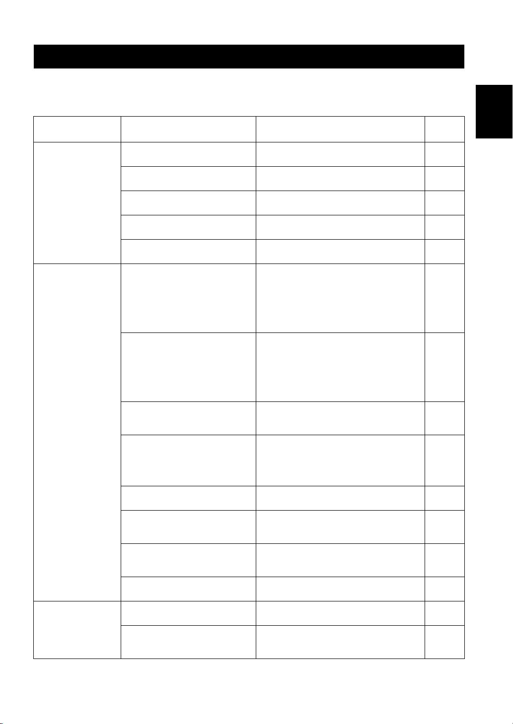
TROUBLESHOOTING
Refer to the chart below if this unit does not function properly. If the problem you are experiencing is not listed below or
if the instructions below do not help, turn off this unit, disconnect the power cable, and then contact the nearest
authorized Yamaha dealer or service center.
Problem Cause Remedy
This unit fails to turn
on.
This unit turns off
suddenly and the
power indicator
blinks.
No sound. Sound is muted. Press MUTE on the remote control or rotate the
The power cable is not connected or the
plug is not completely inserted.
The A AMP is pressed on the remote
control while this unit is turned off.
The impedance setting of the connected
speaker is too small.
The protection circuitry has been activated
because of a short circuit, etc.
There is a problem with the internal
circuitries of this unit.
The speaker wires are touching each other
or shorting out against the rear panel.
The speaker is malfunctioning. Replace the speaker set and press the A (power)
The protection circuitry has been activated
because of excessive input or excessive
volume level.
The protection circuitry has been activated
due to excessive internal temperature.
The IMPEDANCE SELECTOR switch is
not fully slid to either position.
The IMPEDANCE SELECTOR switch is
not set to the correct position.
This unit has been exposed to a strong
external electric shock (such as lightning
or strong static electricity).
There is a problem with the internal
circuitries of this unit.
Incorrect cable connections. Connect the stereo cable for audio units and the
Connect the power cable firmly.
Press A (power) switch on the front panel to on.
Use speaker(s) with proper speaker impedance.
Check that the speaker wires are not touching each
other and then turn the power of this unit back on.
Disconnect the power cable and contact the nearest
authorized Yamaha dealer or service center.
Connect the speaker cables properly and press the A
(power) switch again. The INPUT indicators blink
and the volume is decreased to the lowest setting
automatically, then the INPUT indicators stop
flashing and the last input source selected lights up.
Confirm normal sound output from speakers by
increasing the volume gradually.
switch again. The INPUT indicators blink and the
volume is decreased to the lowest setting
automatically, then the INPUT indicators stop
flashing and the last input source selected lights up.
Confirm normal sound from speakers by increasing
the volume gradually.
Rotate the VOLUME control on the front panel to
decrease the volume level and then turn the power on
again.
Allow about 30 minutes for the temperature inside
this unit to decrease, rotate the VOLUME control on
the front panel to lower the volume and then turn the
power on again. Set the unit in a place where heat can
readily dissipate from the unit.
Turn the power off and slide the IMPEDANCE
SELECTOR switch all the way to the correct position.
Set the IMPEDANCE SELECTOR switch to the
position that corresponds to the impedance of your
speakers.
Turn off this unit, disconnect the power cable, plug it
back in after 30 seconds, then use the unit normally.
Disconnect the power cable and contact the nearest
authorized Yamaha dealer or service center.
VOLUME control.
speaker wires properly. If the problem persists, the
cables may be defective.
See
page
10
2
5
10
—
10
—
—
—
5
5
—
—
7
9
English
13 En
Page 16

TROUBLESHOOTING
Problem Cause Remedy
No sound. Playback has been stopped on the
The sound suddenly
goes off.
Only the speaker on
one side can be
heard.
There is a lack of bass
and no ambience.
A “humming” sound
can be heard.
The volume level
cannot be increased,
or the sound is
distorted.
The sound is
degraded when
listening with
headphones
connected to a CD
player connected to
this unit.
The sound level is
low.
The volume level is
low while playing a
record.
Using the BASS,
TREBLE, BALANCE
and LOUDNESS
controls does not
affect the sound.
connected component.
No appropriate input source has been
selected.
The SPEAKERS selector is not set
properly.
The output audio source setting on the
connected component is not PCM.
The automatic power down function has
activated.
Incorrect cable connections. Connect the cables properly. If the problem persists,
Incorrect setting for the BALANCE
control.
The + and – wires are connected in
reverse at the amplifier or the speakers.
Incorrect cable connections. Connect the audio plugs firmly. If the problem
No connection from the turntable to the
GND terminal.
The component connected to the LINE 2
REC or LINE 3 REC jacks of this unit is
turned off.
This unit is turned off or is in standby
mode.
Sound is muted. Press MUTE on the remote control or rotate the
The loudness control function is
operating.
The turntable is connected to the jacks
other than the PHONO jacks.
The record is being played on a turntable
with an MC cartridge.
The CD DIRECT function or the PURE
DIRECT function is turned on.
Turn the component on and start playback.
Select an appropriate input source with the INPUT
selector on the front panel (or one of the Input
selector buttons on the remote control).
Set the corresponding SPEAKERS selector to A, B or
A+B BI-WIRING position.
Only PCM audio sources can be played via the
DIGITAL (OPTICAL/COAXIAL) jacks of this unit.
Set the output audio source of the connected
component to PCM.
Confirm that there are no other issues causing this
problem, and then turn this unit on again.
To turn off the AUTO POWER STANDBY function,
set the AUTO POWER STANDBY switch to OFF on
the rear panel.
the cables may be defective.
Set the BALANCE control to the appropriate
position.
Connect the speaker wires to the correct + and –
phase.
persists, the cables may be defective.
Make the GND connection between the turntable and
this unit.
Turn on the power of the component.
Turn on the power of this unit.
VOLUME control.
Turn down the volume, set the LOUDNESS control
to the FLAT position, and then adjust the volume
again.
Connect the turntable to the PHONO jacks.
Use a turntable equipped with an MM cartridge.
The CD DIRECT function or the PURE DIRECT
function must be turned off to use those controls.
See
page
11
11
11
16
4
9
3
10
9, 10
9
—
—
7
12
9
9
12
14 En
Page 17
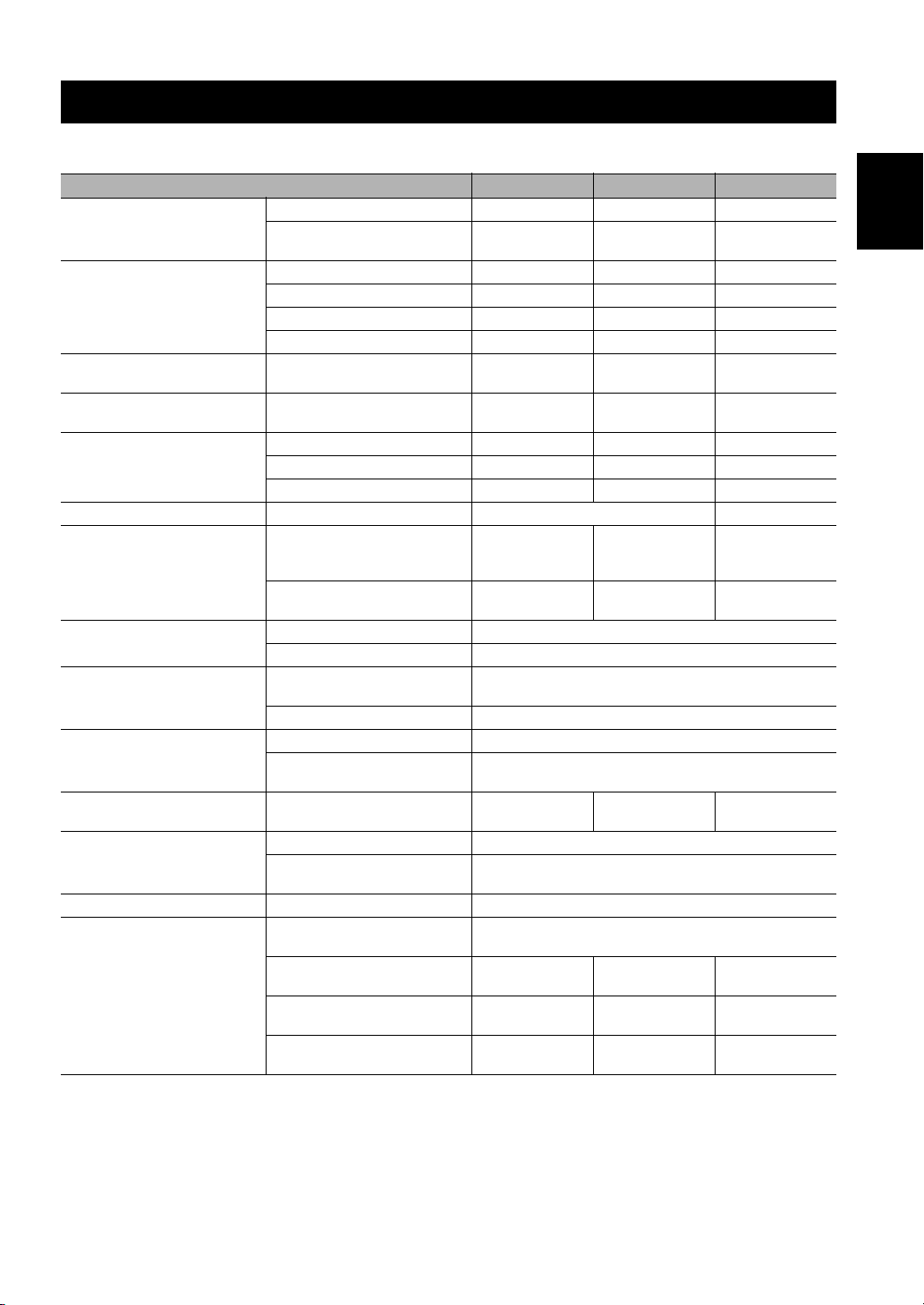
SPECIFICATIONS
AUDIO SECTION
Item A-S701 A-S501 A-S301
8 Ω, 20 Hz to 20 kHz, 0.019% THD 100 W + 100 W 85 W + 85 W 60 W + 60 W
Minimum RMS output power
Dynamic power per channel (IHF)
Maximum power per channel
IEC power
Power band width
Damping factor (SPEAKERS A) 1 kHz, 8 Ω 240 or more 210 or more
Maximum Effective Output Power
(JEITA)
Input sensitivity/Input impedance
Maximum input signal
Output level/Output impedance
PHONES jack rated output/
Impedance
Frequency response
RIAA equalization deviation PHONO (MM) ± 0.5 dB
Total harmonic distortion
6 Ω, 20 Hz to 20 kHz, 0.038% THD
(Except for Asia and China models)
8 Ω 140 W 130 W 100 W
6 Ω 170 W 150 W 120 W
4 Ω 220 W 185 W 140 W
2 Ω 290 W 220 W 150 W
1 kHz, 0.7% THD, 4 Ω
(U.K. and Europe models only)
1 kHz, 0.019% THD, 8 Ω
(U.K. and Europe models only)
0.04% THD, 50 W, 8 Ω 10 Hz to 50 kHz — —
0.04% THD, 42.5 W, 8 Ω — 10 Hz to 50 kHz —
0.04% THD, 30 W, 8 Ω — — 10 Hz to 50 kHz
1 kHz, 10% THD, 8 Ω
(Asia, China and General models
only)
1 kHz, 10% THD, 6 Ω
(General model only)
PHONO (MM) 3.0 mV/47 kΩ
CD, etc. 200 mV/47 kΩ
PHONO (MM) (1 kHz, 0. 03%
THD)
CD etc. (1 kHz, 0.5% THD) 2.2 V or more
REC OUT 200 mV/1.0 kΩ or less
SUBWOOFER OUT (Cut Off
Frequency: 100 Hz)
CD, etc. (Input 1 kHz, 200 mV,
8 Ω)
CD, etc. (20 Hz to 20 kHz) 0 ± 0.5 dB
CD, etc. PURE DIRECT on (10 Hz
to 100 kHz)
PHONO (MM) to REC OUT (20
Hz to 20 kHz, 2.5 V)
CD, etc. to SPEAKERS (20 Hz to
20 kHz, 50 W, 8 Ω)
CD, etc. to SPEAKERS (20 Hz to
20 kHz, 45 W, 8 Ω)
CD, etc. to SPEAKERS (20 Hz to
20 kHz, 30 W, 8 Ω)
120 W + 120 W 100 W + 100 W 70 W + 70 W
160 W 120 W 95 W
115 W 100 W 75 w
145 W 130 W 100 W
170 W — —
45 mV or more
3.5 V/1.2 kΩ
470 mV/470 Ω 430 mV/470 Ω 360 mV/470 Ω
0 ± 1.0 dB
0.03 % or less
0.019 % or less — —
— 0.019 % or less —
— — 0.019 % or less
English
15 En
Page 18
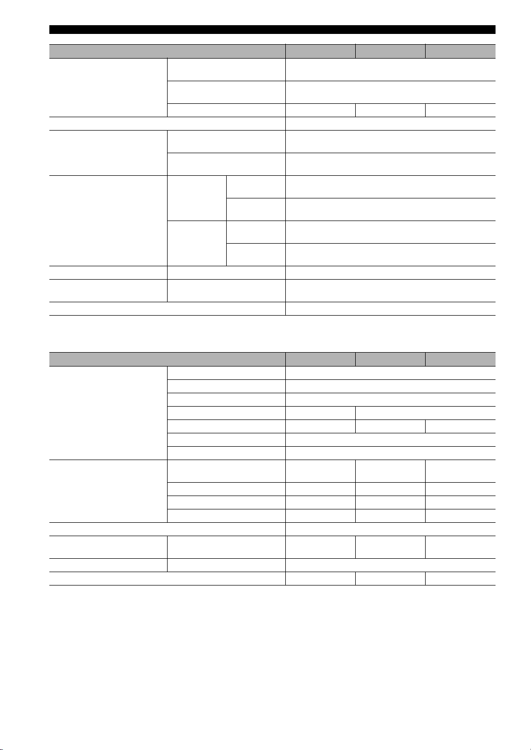
SPECIFICATIONS
Item A-S701 A-S501 A-S301
PHONO (MM)
Signal to noise ratio (IHF-A
network)
Residual noise (IHF-A network) 40 μV
Channel separation
Tone control characteristics
Continuous loudness control Attenuation (1 kHz) – 30 dB
Supported digital audio format
(OPTICAL/COAXIAL)
PCM word depth 24 bit/16 bit
(5 mV input shorted)
CD, etc. PURE DIRECT on
(200 mV input shorted)
CD DIRECT AMP on 104 dB or more — —
CD, etc. (5.1 kΩ input shorted,
1kHz)
CD, etc. (5.1 kΩ input shorted,
10 kHz)
Boost/
BASS
TREBLE
PCM (2-ch) 192/176.4/96/88.2/48/44.1/32 kHz
Cut (20 Hz)
Turnover
frequency
Boost/
Cut (20 kHz)
Turnover
frequency
82 dB or more
99 dB or more
65 dB or more
50 dB or more
± 10 dB
400 Hz
± 10 dB
3.5 kHz
GENERAL
Item A-S701 A-S501 A-S301
U.S.A. and Canada models AC 120 V, 60 Hz
Asia model AC 220-240 V, 50/60 Hz
General model AC 110-120 V/220-240 V, 50/60 Hz
Power supply
Power consumption
Standby power consumption 0.5 W
Maximum power consumption
Dimensions W × H × D 435 × 151 × 387 mm (17-1/8" × 6" × 15-1/4")
Weight 11.2 kg (24.7 lbs) 10.3 kg (22.7 lbs) 9.0 kg (19.8 lbs)
Specifications are subject to change without notice.
China model — AC 220 V, 50 Hz
Korea model — — AC 220 V, 60 Hz
Australia model AC 240 V, 50 Hz
U.K. and Europe models AC 230 V, 50 Hz
U.S.A and Canada, General,
Australia, U.K and Europe models
Asia model 230 W 220 W 170 W
China model — 220 W 170 W
Korea model — — 190 W
1 kHz 6 Ω 10% THD
(General model only)
270 W 240 W 190 W
580 W 510 W 430 W
16 En
Page 19
SPECIFICATIONS
Information for Users on Collection and Disposal of Old Equipment
and Used Batteries
These symbols on the products, packaging, and/or accompanying documents mean that used electrical and
electronic products and batteries should not be mixed with general household waste.
For proper treatment, recovery and recycling of old products and used batteries, please take them to
applicable collection points, in accordance with your national legislation and the Directives 2002/96/EC
and 2006/66/EC.
By disposing of these products and batteries correctly, you will help to save valuable resources and prevent
any potential negative effects on human health and the environment which could otherwise arise from
inappropriate waste handling.
For more information about collection and recycling of old products and batteries, please contact your
local municipality, your waste disposal service or the point of sale where you purchased the items.
[Information on Disposal in other Countries outside the European Union]
These symbols are only valid in the European Union. If you wish to discard these items, please contact
your local authorities or dealer and ask for the correct method of disposal.
Note for the battery symbol (bottom two symbol examples):
This symbol might be used in combination with a chemical symbol. In this case it complies with the
requirement set by the Directive for the chemical involved.
English
17 En
Page 20
ATTENTION : VEUILLEZ LIRE CE QUI SUIT AVANT D’UTILISER L’APPAREIL.
ATTENTION : VEUILLEZ LIRE CE QUI SUIT AVANT D’UTILISER
L’APPAREIL.
1 Pour utiliser l’appareil au mieux de ses possibilités, lisez
attentivement ce mode d’emploi. Conservez-le
soigneusement pour référence.
2 Installez cet ensemble audio dans un endroit bien aéré,
frais, sec et propre - veillez à ce qu’il soit à l’abri de la
lumière directe du soleil, des sources de chaleur, des
vibrations, des poussières, de l’humidité et/ou du froid.
Pour une ventilation correcte, ménagez l’espace
minimum suivant autour de cet appareil.
Au-dessus : 30 cm
À l’arrière : 20 cm
Sur les côtés : 20 cm
3 Placez l’appareil loin des équipements, moteurs et
transformateurs électriques, pour éviter les ronflements
parasites.
4 N’exposez pas l’appareil à des variations brutales de
température, ne le placez pas dans un environnement très
humide (par exemple dans une pièce contenant un
humidificateur) car cela peut entraîner la condensation
d’humidité à l’intérieur de l’appareil qui elle-même peut
être responsable de décharge électrique, d’incendie, de
dommage à l’appareil ou de blessure corporelle.
5 Evitez d’installer l’appareil dans un endroit où des objets
peuvent tomber, ainsi que là où l’appareil pourrait être
exposé à des éclaboussures ou des gouttes d’eau. Sur le
dessus de l’appareil, ne placez pas :
– d’autres appareils qui peuvent endommager la surface
de l’appareil ou provoquer sa décoloration.
– des objets se consumant (par exemple, une bougie)
qui peuvent être responsables d’incendie, de
dommage à l’appareil ou de blessure corporelle.
– des récipients contenant des liquides qui peuvent être
à l’origine de décharge électrique ou de dommage à
l’appareil.
6 Ne couvrez pas l’appareil d’un journal, d’une nappe, d’un
rideau, etc. car cela empêcherait l’évacuation de la
chaleur. Toute augmentation de la température intérieure
de l’appareil peut être responsable d’incendie, de
dommage à l’appareil ou de blessure corporelle.
7 Ne branchez pas la fiche du câble d’alimentation de
l’appareil sur une prise secteur aussi longtemps que tous
les raccordements n’ont pas été effectués.
8 Ne pas faire fonctionner l’appareil à l’envers. Il risquerait
de chauffer et d’être endommagé.
9 N’exercez aucune force excessive sur les commutateurs,
les boutons et les cordons.
10 Pour débrancher la fiche du câble d’alimentation au
niveau de la prise secteur, saisissez la fiche et ne tirez pas
sur le cordon.
11 Ne nettoyez pas l’appareil au moyen d’un solvant
chimique, ce qui pourrait endommager la finition.
Utilisez un chiffon sec et propre.
12 N’alimentez l’appareil qu’à partir de la tension prescrite.
Alimenter l’appareil sous une tension plus élevée est
dangereux et peut être responsable d’incendie, de
dommage à l’appareil ou de blessure corporelle. Yamaha
ne saurait être tenue responsable des dommages résultant
de l’alimentation de l’appareil sous une tension autre que
celle prescrite.
13 Pour empêcher tout dommage causé par les éclairs,
déconnectez le câble d’alimentation et toute antenne
extérieure de la prise murale pendant un orage.
14 Ne tentez pas de modifier ni de réparer l’appareil.
Consultez le service Yamaha compétent pour toute
réparation qui serait requise. Le coffret de l’appareil ne
doit jamais être ouvert, quelle que soit la raison.
15 Si vous envisagez de ne pas vous servir de l’appareil
pendant une longue période (par exemple, pendant les
vacances), débranchez la fiche du câble d’alimentation au
niveau de la prise secteur.
16 Lisez la section intitulée « GUIDE DE DÉPANNAGE »
où figurent une liste d’erreurs de manipulation
communes avant de conclure que l’appareil présente une
anomalie de fonctionnement.
17 Avant de déplacer l’appareil, appuyez sur
A (alimentation) pour mettre l’appareil en mode veille,
puis débranchez la fiche du cordon d’alimentation au
niveau de la prise secteur.
18 La condensation se forme lorsque la température
ambiante change brusquement. En ce cas, débranchez la
fiche du câble d’alimentation et laissez l’appareil reposer.
19 La température de l’appareil peut augmenter en raison
d’une utilisation prolongée. En ce cas, coupez
l’alimentation de l’appareil et laissez-le au repos pour
qu’il refroidisse.
20 Installez cet appareil à proximité de la prise secteur et à
un emplacement où la fiche du câble d’alimentation est
facilement accessible.
21 Les piles ne doivent pas être exposées à une chaleur
extrême, par exemple au soleil, à une flamme, etc.
22 Une pression excessive du son par les écouteurs et le
casque d’écoute peut entraîner la perte de l’ouïe.
Cet appareil n’est pas déconnecté du secteur tant qu’il reste
branché à la prise de courant, même si l’appareil en soi est éteint
par la touche A. Il se trouve alors « en veille ». En mode veille,
l’appareil consomme une très faible quantité de courant.
AVERTISSEMENT
POUR RÉDUIRE LES RISQUES D’INCENDIE OU DE
DÉCHARGE ÉLECTRIQUE, N’EXPOSEZ PAS CET
APPAREIL À LA PLUIE OU À L’HUMIDITÉ.
Cette étiquette doit être apposée sur un produit dont le
capot supérieur peut devenir chaud lorsqu’il fonctionne.
i Fr
Page 21
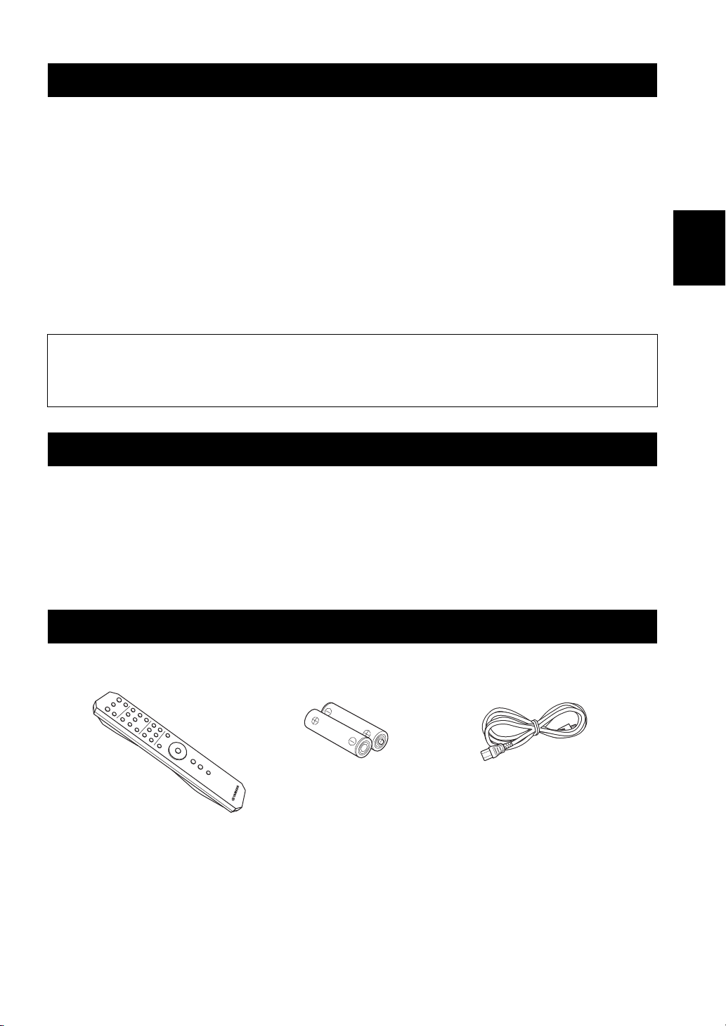
TABLE DES MATIÈRES
FONCTIONS UTILES ..................................1
ACCESSOIRES FOURNIS ..........................1
COMMANDES ET FONCTIONS ...............2
LECTURE.................................................... 11
Lecture d’une source...................................... 11
Réglage du son de votre choix ....................... 12
Panneau avant ...................................................2
Panneau arrière .................................................4
Télécommande..................................................6
GUIDE DE DÉPANNAGE ......................... 13
SPÉCIFICATIONS ..................................... 15
RACCORDEMENTS .................................... 9
Raccordement des enceintes et
des composants sources.................................9
Raccordement du câble d’alimentation...........10
À propos de ce manuel
• Le symbole y attire votre attention sur un conseil d’utilisation.
• Les illustrations utilisées dans ce mode d’emploi représentent l’A-S701.
• Selon le modèle, celui-ci peut ne pas être en vente dans certains pays ou certaines régions.
FONCTIONS UTILES
Cet appareil permet d’effectuer les opérations suivantes :
◆ Profiter de la meilleure qualité sonore des disques
compacts à l’aide de la fonction CD direct (A-S701
uniquement) (voir page 12)
◆ Écouter un son pur de haute fidélité à l’aide de la
fonction Pure Direct (voir page 12)
◆ Économiser de l’énergie à l’aide du commutateur
AUTO POWER STANDBY (voir page 4)
◆ Utiliser la télécommande de cet appareil pour
commander un syntoniseur et/ou un lecteur de CD
Yamaha (voir page 7)
◆ Amplifier les basses en raccordant un caisson de graves
(voir page 9)
Français
ACCESSOIRES FOURNIS
Vérifiez que vous avez reçu tous les articles suivants.
Télécommande Piles (x2)
(AA, R6, UM-3)
Câble d’alimentation
(A-S701 uniquement)
1 Fr
Page 22
Panneau avant
COMMANDES ET FONCTIONS
(A-S701)
1 Commutateur A (alimentation)
Met cet appareil sous et hors tension.
Remarque
Cet appareil consomme une petite quantité d’énergie même
lorsqu’il est hors tension.
2 Témoin d’alimentation
Témoin État
Fortement
éclairé
Faiblement
éclairé
Éteint Cet appareil est « hors tension ».
Cet appareil est « sous tension ».
Cet appareil est en mode « veille ».
Pour plus de détails sur le mode
« veille », voir page 6.
3 Capteur de télécommande
Reçoit les signaux infrarouges émis par la
télécommande.
4 Prise PHONES
Pour brancher votre casque.
5 Sélecteur SPEAKERS
Position du
sélecteur
OFF
A ou B
A+B BI-WIRING
État des enceintes
Les deux jeux d’enceintes sont hors
tension.
Le jeu d’enceintes branché aux bornes
A ou B est sous tension.
Les deux jeux d’enceintes sont sous
tension.
6 Commande BASS
Augmente ou réduit la réponse dans les basses
fréquences.
La position 0 produit une réponse plate.
Plage de commande : –10 dB à +10 dB
7 Commande TREBLE
Augmente ou réduit la réponse dans les hautes
fréquences.
La position 0 produit une réponse plate.
Plage de commande : –10 dB à +10 dB
2 Fr
Page 23
COMMANDES ET FONCTIONS
(A-S701)
Français
8 Commande BALANCE
Équilibre le son reproduit par les enceintes gauche et
droite afin de compenser le déséquilibre sonore.
Remarque
Si vous tournez la commande BALANCE jusqu’à l’extrémité
de L (gauche) ou R (droite), le son du côté opposé du canal
est désactivé.
9 Commande LOUDNESS
Conserve une plage de tonalités complète à n’importe
quel niveau de volume (voir page 12).
0 Sélecteur et témoins INPUT
Sélectionne la source d’entrée que vous souhaitez
écouter. Les témoins de source d’entrée s’allument
lorsque la source d’entrée correspondante est
sélectionnée.
y
Les noms des sources d’entrée correspondent à ceux des
prises de raccordement du panneau arrière.
A Commande VOLUME
Augmente ou réduit le niveau sonore en sortie.
B Touche et témoin CD DIRECT AMP
(A-S701 uniquement)
Reproduit le son d’un CD avec la meilleure qualité de
signal (voir page 12).
Le témoin situé au-dessus de cette fonction s’allume
lorsqu’elle est active.
C Touche et témoin PURE DIRECT
Reproduit toute source d’entrée avec le son le plus pur
possible (voir page 12).
Le témoin situé au-dessus de cette fonction s’allume
lorsqu’elle est active.
3 Fr
Page 24
COMMANDES ET FONCTIONS
Panneau arrière
(A-S501/S301)
(A-S701)
1 Prises d’entrée CD
Pour brancher un lecteur de CD (voir page 9).
2 Prises PHONO et borne GND
Pour raccorder un tourne-disque utilisant une
cartouche MM et pour mettre la borne à la terre
(voir page 9).
3 Prises d’entrée/de sortie audio
Pour raccorder des périphériques externes, tels qu’un
syntoniseur, etc. (voir page 9).
4 Prise DIGITAL (OPTICAL)
Pour raccorder un composant doté d’une sortie
optique numérique (voir page 9).
5 Prise DIGITAL (COAXIAL)
Pour raccorder un composant doté d’une sortie
coaxiale numérique (voir page 9).
6 Prise DC OUT
Pour assurer l’alimentation électrique d’un accessoire
audiovisuel Yamaha. Pour plus de détails sur les
raccordements, reportez-vous au mode d’emploi de
l’accessoire audiovisuel.
7 Bornes SPEAKERS A/B
Pour le raccordement d’un ou deux jeux d’enceintes
(voir page 9).
8 Prise SUBWOOFER OUT
Pour raccorder un caisson de graves doté d’un
amplificateur intégré (voir page 9).
y
La prise SUBWOOFER OUT atténue les signaux de plus de
90 Hz.
9 Commutateur AUTO POWER STANDBY
Position du
commutateur
ON
OFF
L’appareil entre automatiquement en
mode veille s’il n’est pas utilisé
pendant 8 heures.
L’appareil n’entre pas
automatiquement en mode veille.
État
4 Fr
Page 25
COMMANDES ET FONCTIONS
(A-S501/S301)
(A-S701)
Français
0 VOLTAGE SELECTOR (Pour le modèle général
uniquement)
Pour régler votre tension secteur locale (voir page 10).
A Commutateur IMPEDANCE SELECTOR
ATTENTION
Ne modifiez pas le commutateur IMPEDANCE
SELECTOR lorsque cet appareil est sous tension, car
vous risqueriez de l’endommager.
Si le commutateur IMPEDANCE SELECTOR ne peut
pas être correctement réglé dans l’une ou l’autre
position, retirez le câble d’alimentation et faites
glisser le commutateur à fond sur l’une ou l’autre
position.
Sélectionnez la position du commutateur selon
l’impédance des enceintes.
Raccordement
des enceintes
SPEAKERS A
ou
SPEAKERS B
SPEAKERS A
et
SPEAKERS B
Bifilaire
Impédance des
enceintes
6 Ω ou plus HIGH
4 Ω ou plus LOW
12 Ω ou plus HIGH
8 Ω ou plus LOW
6 Ω ou plus HIGH
4Ω ou plus LOW
Position du
commutateur
B AC IN (A-S701)
Pour brancher le câble d’alimentation fourni sur une
prise secteur (voir page 10).
Câble d’alimentation (A-S501/S301)
Pour brancher cet appareil sur une prise secteur (voir
page 10).
5 Fr
Page 26
COMMANDES ET FONCTIONS
Télécommande
1 Émetteur de signal infrarouge
Envoie des signaux infrarouges.
2
A AMP
Met cet appareil sous tension ou en mode veille.
3 OPEN/CLOSE
Ouvre/ferme le plateau de disque du lecteur de CD
Ya ma ha .
Pour plus de détails, reportez-vous au mode d’emploi
de votre lecteur de CD.
Remarque
Même si vous utilisez un lecteur de CD Yamaha, il se peut
que certains composants et certaines fonctions ne soient pas
disponibles.
6 Fr
(A-S501/S301)(A-S701)
4 A CD
Met le lecteur de CD Yamaha sous tension ou en mode
veille. Pour plus de détails, reportez-vous au mode
d’emploi de votre lecteur de CD.
Remarque
Même si vous utilisez un lecteur de CD Yamaha, il se peut
que certains composants et certaines fonctions ne soient pas
disponibles.
5 CD DIRECT AMP (A-S701 uniquement)
Reproduit le son d’un CD avec la meilleure qualité de
signal (voir page 12).
6 Touches du sélecteur d’entrée
Sélectionne la source d’entrée que vous souhaitez
écouter.
y
Les noms des sources d’entrée correspondent à ceux des
prises de raccordement du panneau arrière.
Page 27

COMMANDES ET FONCTIONS
7 VOLUME +/–
Augmente ou réduit le niveau sonore en sortie.
8 MUTE
Réduit le niveau de volume sélectionné d’environ
20 dB. Appuyez de nouveau sur cette touche pour
rétablir le niveau sonore antérieur. Pour annuler la
mise en sourdine, vous pouvez également appuyer sur
VOLUME +/–.
Le témoin d’entrée du panneau avant pour la source
d’entrée sélectionnée clignote lorsque le son est
désactivé.
9 PURE DIRECT
Reproduit toute source d’entrée avec le son le plus pur
possible (voir page 12).
0 Touches de commande d’un syntoniseur
Yam aha
Vous pouvez utiliser les touches suivantes pour
commander les différentes fonctions d’un syntoniseur
Ya ma ha .
Pour plus d’informations, reportez-vous au mode
d’emploi des composants.
BAND
Sélectionne la bande de réception (FM/AM).
TUNING jj / ii
Sélectionne la fréquence de syntonisation.
MEMORY
Mémorise la station FM/AM actuelle sous la forme
d’une présélection.
A Touches de commande d’un lecteur de CD
Yama ha
Vous pouvez utiliser les touches suivantes pour
commander un lecteur de CD Yamaha.
Pour plus d’informations, reportez-vous au mode
d’emploi des composants.
w Rembobine
f Effectue la lecture en avance rapide
DISC SKIP Passe au disque suivant dans un
chargeur multidisque (A-S501/S301
uniquement)
e Suspend la lecture
b Recule
a Av anc e
p Démarre la lecture
s Arrête la lecture
Remarque
Même si vous utilisez un lecteur de CD Yamaha, il se peut
que certains composants et certaines fonctions ne soient pas
disponibles.
Français
PRESET j / i
Sélectionne une station FM/AM présélectionnée.
Remarque
Même si vous utilisez un syntoniseur Yamaha, il se peut que
certains composants et fonctions ne soient pas disponibles.
7 Fr
Page 28

COMMANDES ET FONCTIONS
■ Installation des piles ■ Portée de la télécommande
Dirigez la télécommande vers le capteur de télécommande
de cet appareil et restez dans la zone de portée de la
télécommande indiquée ci-dessous.
Environ
Piles AA, R6, UM-3
■ Remarques sur la télécommande et les piles
• Entre la télécommande et cet appareil, l’espace doit être libre d’obstacle.
• Faites attention à ne pas renverser d’eau ou d’autres liquides sur la télécommande.
• Faites attention à ne pas laisser tomber la télécommande.
• Ne conservez pas ou ne rangez pas la télécommande dans les endroits suivants :
– lieux très humides, par exemple près d’une salle de bains
– lieux très chauds, par exemple près d’un appareil de chauffage ou d’un poêle
– lieux exposés à des températures très basses
– lieux poussiéreux
• Remplacez toutes les piles lorsque vous remarquez que la portée de la télécommande est plus courte.
• Retirez immédiatement les piles épuisées de la télécommande pour éviter tout risque d’explosion ou de fuite d’acide.
• Si les piles fuient, mettez-les au rebut immédiatement, en évitant de toucher le produit qui a fui. En cas de contact entre le produit qui
a fui et votre peau, vos yeux ou votre bouche, rincez-les immédiatement et consultez un médecin. Avant d’installer de nouvelles
piles, nettoyez soigneusement le logement des piles.
• Ne combinez jamais des piles neuves et des piles usagées. Cela peut réduire la durée de vie des piles neuves ou faire fuir les
anciennes.
• N’utilisez pas non plus des piles de types différents (par exemple, des piles alcalines et des piles au manganèse). Des piles
d’apparence identique peuvent présenter des caractéristiques différentes.
• Les piles doivent être mises au rebut conformément à la réglementation locale.
• Conservez les piles dans un endroit hors de portée des enfants.
Les piles peuvent être dangereuses si un enfant les met dans sa bouche.
• Si vous prévoyez de ne pas utiliser cet appareil pendant un certain temps, retirez les piles. Sinon, les piles s’usent et risquent de fuir,
ce qui peut endommager cet appareil.
6m
Télécommande
8 Fr
Page 29
RACCORDEMENTS
Raccordement des enceintes et des composants sources
Assurez-vous de raccorder L (gauche) sur L, R (droite) sur R, « + » sur « + » et « – » sur « – ». Si le raccordement est
défectueux, aucun son n’est émis par l’enceinte, et si la polarité de la connexion est incorrecte, les sons manquent de
naturel et de composantes graves. Reportez-vous au mode d’emploi de chaque composant.
Assurez-vous d’utiliser les câbles RCA ou un câble optique pour raccorder les composants audio.
ATTENTION
Ne raccordez pas cet appareil ou d’autres composants au secteur tant que toutes les connexions entre les composants ne
sont pas établies.
Tourne-disque
Syntoniseur
Lecteur de
DVD, etc.
Téléviseur,
etc.
Lecteur de disque
Blu-ray, etc.
Enceintes A
GaucheDroite
Français
Sortie
audio
GND
Sortie
audio
Lecteur de
CD
Sortie
audio
Sortie
audio
Platine à
cassette,
etc.
Sortie
audio
Entrée
audio
Entrée
audio
Enregistreur
de CD, etc.
Sortie
audio
Sortie
audio
Sortie
audio
Caisson de
graves
GaucheDroite
Enceintes B
Seuls les signaux PCM peuvent être transmis aux prises DIGITAL (OPTICAL/COAXIAL) de cet appareil. Pour plus
de détails sur les signaux PCM pris en charge, voir page 15.
y
• Les prises PHONO sont destinées au raccordement d’un tourne-disque doté d’une cartouche MM.
• Raccordez votre tourne-disque à la borne GND afin de réduire le bruit dans le signal. Toutefois, il se peut que vous entendiez moins de
bruit en débranchant certains tourne-disques de la borne GND.
9 Fr
Page 30
RACCORDEMENTS
■ Prises REC
• Les signaux audio ne sont pas émis par les prises de
sortie LINE 2 REC ou LINE 3 REC lorsque LINE 2 ou
LINE 3 est sélectionné avec le sélecteur INPUT.
• Les commandes VOLUME, BASS, TREBLE, BALANCE
et LOUDNESS et la fonction CD DIRECT (ou la fonction
PURE DIRECT) n’ont aucun effet sur la source enregistrée.
■ Raccordement des câbles d’enceinte
1 Retirez environ 10 mm d’isolation à l’extrémité de
chaque câble d’enceinte.
2 Torsadez fermement les fils dénudés du câble.
3 Dévissez le bouton.
4 Insérez un fil dénudé dans l’orifice situé sur le côté de
chaque borne.
5 Serrez le bouton pour fixer le fil.
10 mm
Rouge : positif (+)
Noir : négatif (–)
ATTENTION
• Réglez le commutateur IMPEDANCE SELECTOR selon
l’impédance des enceintes à raccorder (voir page 5).
• Ne laissez pas les fils d’enceinte dénudés se toucher ni
entrer en contact avec les pièces métalliques de cet
appareil. Cela risquerait d’endommager cet appareil et/
ou les enceintes.
■ Raccordement via la fiche banane
(modèles pour l’Amérique du Nord,
modèles généraux et modèles pour la
Chine et l’Australie uniquement)
1 Vissez le bouton.
2 Insérez la fiche banane dans l’extrémité de la borne
correspondante.
Panneau arrière
Enceinte
Raccordez l’autre enceinte à l’autre jeu de bornes en
procédant de la même manière.
Remarque
Lorsque vous établissez des connexions bifilaires, retirez les
ponts de court-circuitage ou les câbles des enceintes. Pour plus
d’informations, reportez-vous aux modes d’emploi des enceintes.
y
Pour utiliser les connexions bifilaires, réglez le sélecteur
SPEAKERS du panneau avant sur la position A+B BI-WIRING.
Raccordement du câble
d’alimentation
ATT ENT ION
(Modèle général uniquement)
Avant de brancher le câble d’alimentation, assurez-vous
d’avoir réglé le VOLTAGE SELECTOR de cet appareil en
fonction de votre tension locale. Un réglage incorrect du
VOLTAGE SELECTOR peut provoquer un incendie et
endommager cet appareil.
■ AC IN (A-S701)
Une fois tous les autres raccordements effectués, branchez
le câble d’alimentation fourni sur AC IN.
■ Câble d’alimentation (A-S501/S301)
Une fois tous les autres raccordements effectués, branchez
le câble d’alimentation fourni sur une prise secteur.
Fiche banane
■ Connexion bifilaire
Si les enceintes prennent en charge la connexion bifilaire,
leur haut-parleur aigu/médium et leur haut-parleur de
graves peuvent être entraînés indépendamment grâce aux
raccordements indiqués dans le schéma ci-dessous, vous
permettant ainsi d’écouter des sons nets des gammes aiguë
et médium.
10 Fr
Vers la prise
secteur
(A-S501/S301)
Vers la prise
secteur
(A-S701)
Page 31

LECTURE
Lecture d’une source
SPEAKERS VOLUME
(A-S701)
INPUTA
A AMP
Touches du
sélecteur
d’entrée
VOLUME +/–
1 Tournez la commande VOLUME du panneau
avant à fond dans le sens inverse des
aiguilles d’une montre afin de ne pas lire fort
et brusquement les sons.
4 Tournez le sélecteur SPEAKERS du panneau
avant afin de sélectionner SPEAKERS A, B
ou A+B BI-WIRING.
y
Réglez le sélecteur SPEAKERS sur la position A+B BI-WIRING
si deux jeux d’enceintes sont raccordés à l’aide de connexions
bifilaires ou si vous utilisez deux jeux d’enceintes simultanément
(A et B).
5 Lisez la source d’entrée sélectionnée.
6 Tournez la commande VOLUME du panneau
avant (ou appuyez sur les touches VOLUME
+/– de la télécommande) pour régler le
niveau sonore en sortie.
y
Vous pouvez régler le son de votre choix à l’aide des commandes
BASS, TREBLE, BALANCE et LOUDNESS, de la touche CD
DIRECT AMP ou de la touche PURE DIRECT du panneau
avant.
7 Une fois l’écoute terminée, poussez vers
l’extérieur le commutateur A (alimentation)
du panneau avant pour mettre cet appareil
hors tension.
y
Si vous appuyez sur la touche A AMP de la télécommande alors
que le commutateur A (alimentation) du panneau avant est en
position d’activation, cet appareil entre en mode veille. Appuyez
à nouveau sur la touche A AMP pour mettre cet appareil sous
tension.
Français
2 Appuyez sur le commutateur A (alimentation)
du panneau avant pour mettre cet appareil
sous tension.
3 Tournez le sélecteur INPUT du panneau avant
(ou appuyez sur l’une des touches du
sélecteur d’entrée de la télécommande) pour
sélectionner la source d’entrée à écouter.
Le témoin correspondant à la source d’entrée
sélectionnée s’allume.
11 Fr
Page 32

LECTURE
Réglage du son de votre choix
VOLUMELOUDNESS
■ Reproduction d’un son pur de haute
fidélité (PURE DIRECT)
Lorsque la fonction PURE DIRECT est active, il est
possible de réduire le bruit en contournant le circuit que le
signal d’entrée audio n’utilise pas et en arrêtant
l’alimentation électrique du circuit.
Par conséquent, vous pouvez lire de la musique en
bénéficiant d’un son direct dans toutes les sources
d’entrée.
Le témoin situé au-dessus de la touche PURE DIRECT
s’allume lorsque cette fonction est active.
(A-S701)
CD DIRECT
AMP
PURE
DIRECT
■ Écoute simplifiée des aigus et des
graves même à faible volume
(LOUDNESS)
Profitez d’un son naturel même à faible volume en
abaissant le niveau sonore des sons médium et en
compensant la perte de sensibilité des oreilles humaines
aux aigus et aux graves à faible volume.
ATTENTION
Si la fonction CD DIRECT AMP (ou la fonction PURE
DIRECT) est activée alors que la commande LOUDNESS
est réglée à un certain niveau, les signaux d’entrée
contournent la correction physiologique, entraînant ainsi
une augmentation soudaine du niveau sonore en sortie.
Pour éviter d’altérer votre ouïe ou d’endommager les
enceintes, veillez à appuyer sur la touche CD DIRECT
AMP (ou la touche PURE DIRECT) APRÈS avoir réduit
le niveau sonore en sortie ou APRÈS avoir vérifié que
la commande LOUDNESS est correctement réglée.
1 Réglez la commande LOUDNESS sur la
position FLAT.
2 Tournez la commande VOLUME du panneau
avant (ou appuyez sur les touches VOLUME
+/– de la télécommande) pour régler le
niveau sonore en sortie sur le niveau
d’écoute le plus élevé de votre choix.
Remarque
Les commandes BASS, TREBLE, BALANCE et LOUDNESS ne
fonctionnent pas lorsque la fonction PURE DIRECT est active.
■ Reproduction du son d’un CD avec la
meilleure qualité sonore (CD DIRECT
AMP) (A-S701 uniquement)
Lors de la sélection d’une source d’entrée autre qu’un CD,
si vous appuyez sur la touche CD DIRECT AMP, la
source d’entrée bascule vers CD.
Fonction CD Direct Amp
Arrêtez l’alimentation électrique du circuit inutile pour
la lecture de CD, convertissez le signal d’entrée pour la
phase normale et la phase inverse, puis équilibrez le
transfert pour le volume électronique. Les effets suivants
permettent d’offrir un son plus fidèle à l’original.
• amélioration du rapport signal/bruit
• suppression du bruit externe
• réduction de la distorsion
Remarques
• Les commandes BASS, TREBLE, BALANCE et LOUDNESS
ne fonctionnent pas lorsque la fonction CD DIRECT AMP est
active.
• Veillez à brancher le lecteur de CD aux prises d’entrée CD si
vous utilisez la fonction CD direct.
• La fonction CD DIRECT AMP se désactive si l’opération
suivante est effectuée.
– Sélectionnez une source d’entrée autre que CD pour le
sélecteur INPUT.
– La fonction PURE DIRECT s’active.
3 Tournez la commande LOUDNESS dans le
sens inverse des aiguilles d’une montre
jusqu’à l’obtention du volume de votre choix.
12 Fr
Page 33

GUIDE DE DÉPANNAGE
Reportez-vous au tableau suivant si cet appareil ne fonctionne pas comme il devrait. Si le problème que vous rencontrez
n’est pas mentionné ci-dessous, ou encore si les actions correctives suggérées sont sans effet, mettez cet appareil hors
tension, débranchez le câble d’alimentation et prenez contact avec le revendeur ou le service après-vente agréé Yamaha
le plus proche.
Anomalies Causes possibles Actions correctives
Impossible de mettre
cet appareil sous
tension.
Cet appareil se met
brusquement hors
tension et le témoin
d’alimentation
clignote.
Aucun son. Le son est désactivé. Appuyez sur la touche MUTE de la télécommande ou
Le câble d’alimentation n’est pas branché
convenablement, ou pas branché du tout.
Vous avez appuyé sur la touche A AMP
de la télécommande alors que cet appareil
était hors tension.
Le réglage de l’impédance de l’enceinte
raccordée est trop faible.
Le circuit de protection a été actionné du
fait de la présence d’un court-circuit, etc.
Un problème lié aux circuits internes de
cet appareil est survenu.
Les fils d’enceinte se touchent ou sont en
court-circuit avec le panneau arrière.
L’enceinte est défectueuse.
Le circuit de protection a été actionné en raison
d’un niveau d’entrée ou de volume excessif.
Le circuit de protection a été actionné en
raison d’une température interne
excessive.
Le commutateur IMPEDANCE
SELECTOR n’est pas correctement réglé
sur l’une ou l’autre position.
Le commutateur IMPEDANCE SELECTOR
n’est pas réglé sur la position appropriée.
Cet appareil a été soumis à une forte décharge
électrique (provoquée par exemple par un
orage ou une décharge d’électricité statique).
Un problème lié aux circuits internes de
cet appareil est survenu.
Raccordement incorrect des câbles. Branchez correctement le câble stéréo pour appareils
Branchez fermement le câble d’alimentation.
Enfoncez le commutateur A (alimentation) du
panneau avant sur la position d’activation.
Utilisez une ou plusieurs enceintes avec une
impédance correcte.
Vérifiez que les fils des enceintes ne se touchent pas,
puis remettez cet appareil sous tension.
Débranchez le câble d’alimentation et prenez contact
avec le revendeur ou le service après-vente agréé
Yamaha le plus proche.
Raccordez correctement les câbles d’enceinte et enfoncez
à nouveau le commutateur
INPUT clignotent et le volume passe automatiquement
au réglage le plus bas, puis les témoins INPUT cessent de
clignoter et la dernière source d’entrée sélectionnée
s’allume. Vérifiez que le son reproduit par les enceintes
est correct en augmentant graduellement le volume.
Remplacez le jeu d’enceintes et enfoncez à nouveau le
commutateur
et le volume passe automatiquement au réglage le plus bas, puis
les témoins INPUT cessent de clignoter et la dernière source
d’entrée sélectionnée s’allume. Vérifiez que le son reproduit par
les enceintes est correct en augmentant graduellement le volume.
Tournez la commande VOLUME du panneau avant pour réduire
le niveau de volume, puis remettez l’appareil sous tension.
Laissez la température à l’intérieur de cet appareil diminuer
pendant environ 30 minutes, tournez la commande
VOLUME du panneau avant pour réduire le volume, puis
remettez l’appareil sous tension. Installez l’appareil à un
endroit où la chaleur qu’il dégage peut se dissiper aisément.
Mettez l’appareil hors tension et faites glisser le
commutateur IMPEDANCE SELECTOR à fond sur la
position appropriée.
Placez le commutateur IMPEDANCE SELECTOR sur la
position correspondant à l’impédance de vos enceintes.
Mettez cet appareil hors tension, débranchez le câble
d’alimentation, rebranchez-le après 30 secondes, puis
utilisez-le normalement.
Débranchez le câble d’alimentation et prenez contact
avec le revendeur ou le service après-vente agréé
Yamaha le plus proche.
tournez la commande VOLUME.
audio et les fils d’enceinte. Si l’anomalie persiste, il
se peut que les câbles soient défectueux.
A
(alimentation). Les témoins INPUT clignotent
A
(alimentation). Les témoins
Voir
page
Français
10
2
5
10
—
10
—
—
—
5
5
—
—
7
9
13 Fr
Page 34

GUIDE DE DÉPANNAGE
Anomalies Causes possibles Actions correctives
Aucun son. La lecture a été interrompue sur le
Le son se coupe
soudainement.
Seule l’enceinte de
gauche ou de droite
émet des sons.
Basses insuffisantes
et absence
d’ambiance.
Un
« bourdonnement »
se fait entendre.
Impossible
d’augmenter le niveau
de volume, ou le son
est déformé.
Le son est de moins
bonne qualité lorsque
vous écoutez avec le
casque raccordé au
lecteur de CD
connecté à cet
appareil.
Le niveau sonore est
faible.
Le niveau sonore est
trop faible pendant la
lecture d’un disque.
L’utilisation des
commandes BASS,
TREBLE, BALANCE et
LOUDNESS n’affecte
pas le son.
composant connecté.
Aucune source d’entrée appropriée n’est
sélectionnée.
Le sélecteur SPEAKERS n’est pas
correctement réglé.
Le réglage de la source audio de sortie du
composant raccordé n’est pas PCM.
La fonction de mise hors tension
automatique a été activée.
Raccordement incorrect des câbles. Raccordez correctement les câbles. Si l’anomalie
Réglage incorrect de la commande
BALANCE.
Les fils + et – sont inversés sur
l’amplificateur ou les enceintes.
Raccordement incorrect des câbles. Raccordez fermement les fiches audio. Si l’anomalie
Pas de connexion du tourne-disque à la
borne GND.
Le composant raccordé aux prises LINE 2
REC ou LINE 3 REC de cet appareil est
hors tension.
Cet appareil est hors tension ou en mode
veille.
Le son est désactivé. Appuyez sur la touche MUTE de la télécommande ou
La fonction de la commande Loudness est
active.
Le tourne-disque est raccordé à d’autres
prises que les prises PHONO.
La lecture du disque s’effectue sur un
tourne-disque doté d’une cartouche MC.
La fonction CD DIRECT ou la fonction
PURE DIRECT s’active.
Mettez le composant sous tension et lancez la lecture.
Sélectionnez une source d’entrée appropriée à l’aide
du sélecteur INPUT du panneau avant (ou de l’une
des touches du sélecteur d’entrée de la
télécommande).
Réglez le sélecteur SPEAKERS correspondant sur la
position A, B ou A+B BI-WIRING.
Seuls les sources audio PCM peuvent être lues via les
prises DIGITAL (OPTICAL/COAXIAL) de cet
appareil.
Réglez la source audio de sortie du composant
raccordé sur PCM.
Vérifiez qu’aucune autre anomalie n’a causé le
problème, puis remettez cet appareil sous tension.
Pour désactiver la fonction AUTO POWER
STANDBY, réglez le commutateur AUTO POWER
STANDBY sur OFF sur le panneau arrière.
persiste, il se peut que les câbles soient défectueux.
Réglez la commande BALANCE sur la position
appropriée.
Raccordez les fils d’enceinte en respectant la phase +
et –.
persiste, il se peut que les câbles soient défectueux.
Raccordez le tourne-disque à la borne GND de cet
appareil.
Mettez le composant sous tension.
Mettez cet appareil sous tension.
tournez la commande VOLUME.
Réduisez le volume, réglez la commande
LOUDNESS sur la position FLAT, puis réajustez le
volume.
Raccordez le tourne-disque aux prises PHONO.
Utilisez un tourne-disque équipé d’une cartouche
MM.
La fonction CD DIRECT ou la fonction PURE
DIRECT doit être désactivée pour utiliser ces
commandes.
Voir
page
11
11
11
16
4
9
3
10
9, 10
9
—
—
7
12
9
9
12
14 Fr
Page 35

SPÉCIFICATIONS
SECTION AUDIO
Élément A-S701 A-S501 A-S301
8 Ω, 20 Hz à 20 kHz, 0,019 % THD 100 W + 100 W 85 W + 85 W 60 W + 60 W
Puissance minimale de sortie
efficace (RMS)
Puissance dynamique par canal
(IHF)
Puissance maximale par canal
Puissance selon la CEI
Largeur de la bande de puissance
Coefficient d’amortissement
(SPEAKERS A)
Puissance de sortie maximale
efficace (JEITA)
Sensibilité/impédance d’entrée
Signal d’entrée maximal
Niveau/impédance de sortie
Impédance/sortie nominale de la
prise PHONES
Réponse en fréquence
Écart d’égalisation RIAA PHONO (MM) ± 0,5 dB
Distorsion harmonique totale
6 Ω, 20 Hz à 20 kHz, 0,038 % THD
(Sauf modèles pour l’Asie et la
Chine)
8 Ω 140 W 130 W 100 W
6 Ω 170 W 150 W 120 W
4 Ω 220 W 185 W 140 W
2 Ω 290 W 220 W 150 W
1 kHz, 0,7 % THD, 4 Ω
(Modèles pour le Royaume-Uni et
l’Europe uniquement)
1 kHz, 0,019 % THD, 8 Ω
(Modèles pour le Royaume-Uni et
l’Europe uniquement)
0,04 % THD, 50 W, 8 Ω 10 Hz à 50 kHz — —
0,04 % THD, 42,5 W, 8 Ω — 10 Hz à 50 kHz —
0,04 % THD, 30 W, 8 Ω — — 10 Hz à 50 kHz
1kHz, 8Ω 240 ou plus 210 ou plus
1 kHz, 10 % THD, 8 Ω
(Modèles pour l’Asie , modèles pour
la Chine et modèles généraux
uniquement)
1 kHz, 10 % THD, 6 Ω
(Modèle général uniquement)
PHONO (MM) 3,0 mV/47 kΩ
CD, etc. 200 mV/47 kΩ
PHONO (MM) (1 kHz, 0,03 %
THD)
CD, etc. (1 kHz, 0,5 % THD) 2,2 V ou plus
REC OUT 200 mV/1,0 kΩ ou moins
SUBWOOFER OUT (fréquence de
coupure : 100 Hz)
CD, etc. (entrée 1 kHz, 200 mV,
8 Ω)
CD, etc. (20 Hz à 20 kHz) 0 ± 0,5 dB
CD, etc. PURE DIRECT active
(10 Hz à 100 kHz)
PHONO (MM) vers REC OUT
(20 Hz à 20 kHz, 2,5 V)
CD, etc. vers SPEAKERS (20 Hz à
20 kHz, 50 W, 8 Ω)
CD, etc. vers SPEAKERS (20 Hz à
20 kHz, 45 W, 8 Ω)
CD, etc. vers SPEAKERS (20 Hz à
20 kHz, 30 W, 8 Ω)
120 W + 120 W 100 W + 100 W 70 W + 70 W
160 W 120 W 95 W
115W 100W 75W
145 W 130 W 100 W
170 W — —
45 mV ou plus
3,5 V/1,2 kΩ
470 mV/470 Ω 430 mV/470 Ω 360 mV/470 Ω
0 ± 1,0 dB
0,03 % ou moins
019 % ou moins — —
0,
— 0,019 % ou moins —
— — 0,019 % ou moins
Français
15 Fr
Page 36

SPÉCIFICATIONS
Élément A-S701 A-S501 A-S301
PHONO (MM)
(5 mV entrée court-circuitée)
Rapport signal/bruit (réseau IHF-A)
Bruit résiduel (réseau IHF-A) 40 μV
Séparation de canaux
Caractéristiques du contrôle du son
Commande du volume en continu Atténuation (1 kHz) – 30 dB
Format audio numérique pris en
charge (OPTICAL/COAXIAL)
Profondeur de mot PCM 24 bits/16 bits
CD, etc. PURE DIRECT active
(200 mV entrée court-circuitée)
CD DIRECT AMP active 104 dB ou plus — —
CD, etc. (5,1 kΩ entrée courtcircuitée, 1 kHz)
CD, etc. (5,1 kΩ entrée courtcircuitée, 10 kHz)
Renforcement/
Coupure
BASS
TREBLE
PCM (2 canaux) 192/176,4/96/88,2/48/44,1/32 kHz
(20 Hz)
Fréquence de
rotation
Renforcement/
Coupure
(20 kHz)
Fréquence de
rotation
82 dB ou plus
99 dB ou plus
65 dB ou plus
50 dB ou plus
± 10 dB
400 Hz
± 10 dB
3,5 kHz
GÉNÉRALITÉS
Élément A-S701 A-S501 A-S301
Modèles pour les États-Unis et le
Canada
Modèle pour l’Asie 220-240 V CA, 50/60 Hz
Modèle général 110-120 V CA/220-240 V CA, 50/60 Hz
Alimentation électrique
Consommation
Consommation maximale en mode veille 0,5 W
Consommation maximale
Dimensions L × H × P 435 × 151 × 387 mm
Poids 11,2 kg 10,3 kg 9,0 kg
Modèle pour la Chine — 220 V CA, 50 Hz
Modèle pour la Corée — — 220 V CA, 60 Hz
Modèle pour l’Australie 240 V CA, 50 Hz
Modèles pour le Royaume-Uni et
l’Europe
Modèles pour les États-Unis et le
Canada, modèles généraux et
modèles pour l’Australie, le
Royaume-Uni et l’Europe
Modèle pour l’Asie 230 W 220 W 170 W
Modèle pour la Chine — 220 W 170 W
Modèle pour la Corée — — 190 W
1kHz 6Ω 10 % THD
(Modèle général uniquement)
270 W 240 W 190 W
580 W 510 W 430 W
Les spécifications peuvent être modifiées sans avis préalable.
120 V CA, 60 Hz
230 V CA, 50 Hz
16 Fr
Page 37

SPÉCIFICATIONS
Information concernant la collecte et le traitement des piles usagées et
des déchets d’équipements électriques et électroniques
Les symboles sur les produits, l’emballage et/ou les documents joints signifient que les produits électriques ou
électroniques usagés ainsi que les piles ne doivent pas être mélangés avec les déchets domestiques habituels.
Pour un traitement, une récupération et un recyclage appropriés des déchets d’équipements électriques et électroniques
et des piles usagées, veuillez les déposer aux points de collecte prévus à cet effet, conformément à la réglementation
nationale et aux Directives 2002/96/EC et 2006/66/EC.
En vous débarrassant correctement des déchets d’équipements électriques et électroniques et des piles usagées, vous
contribuerez à la sauvegarde de précieuses ressources et à la prévention de potentiels effets négatifs sur la santé
humaine qui pourraient advenir lors d’un traitement inapproprié des déchets.
Pour plus d’informations à propos de la collecte et du recyclage des déchets d’équipements électriques et électroniques
et des piles usagées, veuillez contacter votre municipalité, votre service de traitement des déchets ou le point de vente
où vous avez acheté les produits.
[Information sur le traitement dans d’autres pays en dehors de l’Union Européenne]
Ces symboles sont seulement valables dans l’Union Européenne. Si vous souhaitez vous débarrasser de déchets
d’équipements électriques et électroniques ou de piles usagées, veuillez contacter les autorités locales ou votre
fournisseur et demander la méthode de traitement appropriée.
Note pour le symbole « pile » (les deux symboles du bas) :
Ce symbole peut être utilisé en combinaison avec un symbole chimique. Dans ce cas il respecte les exigences établies
par la Directive pour le produit chimique en question.
Français
17 Fr
Page 38

VORSICHT: VOR DER BEDIENUNG DIESES GERÄTES DURCHLESEN.
VORSICHT: VOR DER BEDIENUNG DIESES GERÄTES DURCHLESEN.
1 Um optimales Leistungsvermögen sicherzustellen, lesen
Sie bitte die Anleitung aufmerksam durch. Bewahren Sie
die Anleitung danach für spätere Nachschlagzwecke
sorgfältig auf.
2 Installieren Sie diese Sound-Anlage an einem gut
belüfteten, trockenen, sauberen Ort - entfernt von
direktem Sonnenlicht, Wärmequellen, Erschütterungen,
Staub und Feuchtigkeit. Um eine ausreichende Belüftung
zu gewährleisten, beachten Sie die folgenden
Mindestabstände rund um dieses Gerät.
Oben: 30 cm
Hinten: 20 cm
Seiten: 20 cm
3 Stellen Sie dieses Gerät entfernt von anderen elektrischen
Haushaltgeräten, Motoren oder Transformatoren auf, um
Brummgeräusche zu vermeiden.
4 Setzen Sie dieses Gerät keinen plötzlichen
Temperaturänderungen von kalt auf warm aus, und
stellen Sie dieses Gerät nicht an Orten mit hoher
Luftfeuchtigkeit auf (z.B. in Räumen mit
Luftbefeuchtern), um Kondensation im Inneren des
Gerätes zu vermeiden, da es anderenfalls zu elektrischen
Schlägen, Feuer, Beschädigung dieses Gerätes und/oder
zu persönlichen Verletzungen kommen kann.
5 Vermeiden Sie die Aufstellung dieses Gerätes an Orten,
an welchen Fremdkörper in das Gerät fallen können bzw.
an welchen Flüssigkeiten auf das Gerät verschüttet
werden können. Stellen Sie auf der Oberseite des Gerätes
niemals Folgendes auf:
– Andere Komponenten, da diese Beschädigung und/
oder Verfärbung der Oberfläche dieses Gerätes
verursachen können.
– Brennende Objekte (z.B. Kerzen), da diese Feuer,
Beschädigung des Gerätes und/oder persönliche
Verletzungen verursachen können.
– Mit Flüssigkeiten gefüllte Behälter, da diese umfallen
und die Flüssigkeit auf das Gerät verschütten können,
wodurch es zu elektrischen Schlägen für den
Anwender und/oder zu Beschädigung des Gerätes
kommen kann.
6 Decken Sie dieses Gerät niemals mit Zeitungen,
Tischdecken, Vorhängen usw. ab, damit die Wärmeabfuhr
nicht behindert wird. Falls die Temperatur im Inneren des
Gerätes ansteigt, kann es zu Feuer, Beschädigung des
Gerätes und/oder zu persönlichen Verletzungen kommen.
7 Schließen Sie dieses Gerät erst an eine Wandsteckdose
an, nachdem alle anderen Anschlüsse ausgeführt wurden.
8 Stellen Sie dieses Gerät niemals mit der Unterseite nach
oben auf, da es sonst beim Betrieb zu Überhitzung mit
möglichen Beschädigungen kommen kann.
9 Wenden Sie niemals Gewalt bei der Bedienung der
Schalter, Knöpfe und/oder Kabel an.
10 Wenn Sie das Netzkabel von der Wandsteckdose
abtrennen, fassen Sie immer den Netzstecker an; ziehen
Sie niemals an dem Kabel.
11 Reinigen Sie dieses Gerät niemals mit chemisch
behandelten Tüchern; anderenfalls kann das Finish
beschädigt werden. Verwenden Sie ein reines, trockenes
Tuch.
12 Verwenden Sie nur die für dieses Gerät vorgeschriebene
Netzspannung. Falls Sie eine höhere als die
vorgeschriebene Netzspannung verwenden, kann es zu
Feuer, Beschädigung dieses Gerätes und/oder zu
persönlichen Verletzungen kommen. Yamaha kann nicht
verantwortlich gemacht werden für Schäden, die auf die
Verwendung dieses Gerätes mit einer anderen als der
vorgeschriebenen Spannung zurückzuführen sind.
13 Um Beschädigungen durch Blitzschlag zu vermeiden,
ziehen Sie den Netzstecker von der Netzdose ab, wenn es
ein Gewitter gibt.
14 Versuchen Sie niemals ein Modifizieren oder Ändern
dieses Gerätes. Falls eine Wartung erforderlich ist,
wenden Sie sich bitte an einen Yamaha-Kundendienst.
Das Gehäuse sollte niemals selbst geöffnet werden.
15 Falls Sie das Gerät für längere Zeit nicht verwenden (z.B.
während der Ferien), ziehen Sie den Netzstecker von der
Netzdose ab.
16 Lesen Sie unbedingt den Abschnitt „STÖRUNGSSUCHE“
durch, um übliche Bedienungsfehler zu berichtigen, bevor
Sie auf eine Störung des Gerätes schließen.
17 Bevor Sie dieses Gerät an einen anderen Ort
transportieren, drücken Sie die A-Taste (Netz), um das
Gerät in Bereitschaft zu schalten, und ziehen Sie danach
den Netzstecker aus der Wandsteckdose.
18 Es kommt zu Kondensatbildung, wenn die
Umgebungstemperatur plötzlich ändert. Ziehen Sie den
Netzstecker von der Netzdose ab, und lassen Sie das
Gerät ruhen.
19 Falls Sie das Gerät für längere Zeit in Betrieb halten,
kann sich das Gerät erwärmen. Schalten Sie die
Stromversorgung aus, und lassen Sie danach das Gerät
abkühlen.
20 Stellen Sie dieses Gerät in die Nähe der Steckdose und so
auf, dass der Netzstecker gut zugänglich ist.
21 Die Batterien dürfen nicht starker Hitze wie direktem
Sonnenschein, Feuer o.ä. ausgesetzt werden.
22 Zu starker Schalldruck von Ohrhörern und Kopfhörern
kann zu Gehörschäden führen.
Dieses Gerät ist nicht vom Netz abgetrennt, so lange der
Netzstecker an eine Netzdose angeschlossen ist, auch wenn das
Gerät selbst ausgeschaltet wurde mit A. Dieser Status wird als
Bereitschaftsmodus bezeichnet. Auch in diesem Status weist das
Gerät einen geringen Stromverbrauch auf.
WARNUNG
UM DIE GEFAHR EINES FEUERS ODER EINES
ELEKTROSCHOCKS ZU VERMEIDEN, DARF DAS GERÄT
WEDER REGEN NOCH FEUCHTIGKEIT AUSGESETZT
WERDEN.
Dieses Etikett muss bei Produkten angebracht werden,
deren Oberseite während des Betriebs heiß sein kann.
i De
Page 39

INHALTSVERZEICHNIS
NÜTZLICHE MERKMALE ........................ 1
MITGELIEFERTES ZUBEHÖR ................1
BEDIENELEMENTE UND
FUNKTIONEN ...........................................2
Vorderseite........................................................2
Rückseite...........................................................4
WIEDERGABE ........................................... 11
Wiedergeben einer Signalquelle..................... 11
Einstellen des gewünschten Klangs ...............12
STÖRUNGSSUCHE ................................... 13
TECHNISCHE DATEN.............................. 15
Fernbedienung ..................................................6
ANSCHLÜSSE...............................................9
Anschließen der Lautsprecher und
Quellkomponenten ........................................9
Anschließen des Netzkabels ...........................10
Über diese Anleitung
• y zeigt einen Tipp für Ihre Bedienung an.
• Die Abbildungen in dieser Bedienungsanleitung beziehen sich auf den A-S701.
• Abhängig vom Modell gibt es einige Länder/Regionen, in denen es möglicherweise nicht verkauft wird.
NÜTZLICHE MERKMALE
Mit diesem Gerät können Sie:
◆ Die Wiedergabe der höchsten Klangqualität von
Compact-Discs über die CD-Direkt-Funktion genießen
(nur A-S701) (siehe Seite 12)
◆ Reinen Hi-Fi-Klang mit der Pure-Direct-Funktion
genießen (siehe Seite 12)
◆ Energie sparen durch Verwendung des Schalters
AUTO POWER STANDBY (siehe Seite 4)
◆ Die Fernbedienung dieses Geräts zur Steuerung eines
Tuners und/oder CD-Spielers von Yamaha verwenden
(siehe Seite 7)
◆ Den Bass-Signalanteil durch Anschluss eines
Subwoofers verstärken (siehe Seite 9)
Deutsch
MITGELIEFERTES ZUBEHÖR
Bitte überprüfen Sie, ob Sie alle folgend aufgeführten Teile erhalten haben.
Fernbedienung Batterien (x2)
(AA, R6, UM-3)
Netzkabel
(nur A-S701)
1 De
Page 40

Vorderseite
BEDIENELEMENTE UND FUNKTIONEN
(A-S701)
1 Schalter A (Netzschalter)
Schaltet dieses Gerät ein und aus.
Hinweis
Auch wenn das Gerät ausgeschaltet ist, verbraucht es eine
geringe Menge Strom.
2 Netzanzeige
Anzeige Status
Leuchtet hell Dieses Gerät ist eingeschaltet.
Dieses Gerät ist im
Leuchtet
schwach
Aus Dieses Gerät ist ausgeschaltet.
Bereitschaftsmodus.
Ausführliche Informationen zum
Bereitschaftsmodus finden Sie auf
Seite 6.
3 Fernbedienungssensor
Empfängt Infrarotsignale von der Fernbedienung.
4 Kopfhörerbuchse PHONES
Schließen Sie Ihren Kopfhörer an.
5 Wahlschalter SPEAKERS
Position des
Wahlschalters
OFF
A oder B
A+B BI-WIRING
Lautsprecherstatus
Beide Lautsprecherpaare sind
ausgeschaltet.
Das an die Anschlüsse A oder B
angeschlossene Lautsprecherpaar ist
eingeschaltet.
Beide Lautsprecherpaare sind
eingeschaltet.
6 Regler BASS
Erhöht oder verringert den Pegel der niedrigen
Frequenzen.
In der Position 0 wird ein linearer Frequenzgang
erzeugt.
Regelbereich: –10 dB bis +10 dB
7 Regler TREBLE
Erhöht oder verringert den Pegel der hohen
Frequenzen.
In der Position 0 wird ein linearer Frequenzgang
erzeugt.
Regelbereich: –10 dB bis +10 dB
2 De
Page 41

BEDIENELEMENTE UND FUNKTIONEN
(A-S701)
Deutsch
8 Regler BALANCE
Stellt das Lautstärkeverhältnis zwischen linkem und
rechtem Lautsprecher ein, um Klangunterschiede
auszugleichen.
Hinweis
Wenn Sie den Regler BALANCE bis zum Ende von L (links)
oder R (rechts) drehen, wird die gegenüberliegende
Kanalseite stumm geschaltet.
9 Regler LOUDNESS
Bewirkt einen vollen Klang bei jeder Lautstärke (siehe
Seite 12).
0 Wahlschalter und Anzeigen INPUT
Wählt die Eingangsquelle, die Sie hören möchten. Die
Eingangsquellenanzeigen leuchten, wenn die
entsprechende Eingangsquelle ausgewählt wird.
y
Die Namen der Eingangsquellen entsprechen den Namen der
Anschlussbuchsen an der Rückseite.
A Regler VOLUME
Erhöht oder verringert den Lautstärkepegel.
B Taste und Anzeige CD DIRECT AMP (nur
A-S701)
Reproduziert CD-Klang in der höchsten Signalqualität
(siehe Seite 12).
Die Anzeige darüber leuchtet, wenn diese Funktion
aktiviert ist.
C Taste und Anzeige PURE DIRECT
Zur Wiedergabe des Signals einer beliebigen
Eingangsquelle mit reinstmöglichem Klang (siehe
Seite 12).
Die Anzeige darüber leuchtet, wenn diese Funktion
aktiviert ist.
3 De
Page 42

BEDIENELEMENTE UND FUNKTIONEN
Rückseite
(A-S501/S301)
(A-S701)
1 CD-Eingangsbuchsen
Hier wird ein CD-Spieler angeschlossen (siehe
Seite 9).
2 Buchsen PHONO und Anschluss GND
An den Buchsen wird ein Plattenspieler mit MMTonabnehmer (Moving Magnet) angeschlossen, der
Anschluss dient zur Erdung des Anschlusses (siehe
Seite 9).
3 Audio-Ein-/-Ausgangsbuchsen
Hier werden externe Audiokomponenten
angeschlossen, wie z. B. Tuner usw. (siehe Seite 9).
4 Buchse DIGITAL (OPTICAL)
Hier wird eine Komponente mit einem digitalen
optischen Ausgang angeschlossen (siehe Seite 9).
5 Buchse DIGITAL (COAXIAL)
Hier wird eine Komponente mit einem digitalen
Koaxialausgang angeschlossen (siehe Seite 9).
6 Kopfhörerbuchse DC OUT
Zur Stromversorgung eines Yamaha AV-Zubehörteils.
Ausführliche Informationen zu den Anschlüssen
finden Sie in der Bedienungsanleitung des
AV-Zubehörteils.
7 Anschlüsse SPEAKERS A/B
Schließen Sie hier ein oder zwei Lautsprecherpaare an
(siehe Seite 9).
8 Buchse SUBWOOFER OUT
Hier wird ein Subwoofer mit eingebautem Verstärker
angeschlossen (siehe Seite 9).
y
Die Buchse SUBWOOFER OUT verstärkt Signale über
90 Hz.
9 Schalter AUTO POWER STANDBY
Schalterstellung
ON
OFF
Das Gerät wechselt automatisch in
den Bereitschaftsmodus, wenn es 8
Stunden lang nicht bedient wird.
Das Gerät wechselt nicht automatisch
in den Bereitschaftsmodus.
Status
4 De
Page 43

BEDIENELEMENTE UND FUNKTIONEN
(A-S501/S301)
(A-S701)
Deutsch
0 VOLTAGE SELECTOR (nur allgemeines
Modell)
Hier können Sie die regionale Leitungsspannung
einstellen (siehe Seite 10).
A Schalter IMPEDANCE SELECTOR
VORSICHT
Stellen Sie den Schalter IMPEDANCE SELECTOR
nicht um, solange das Gerät eingeschaltet ist.
Andernfalls kann das Gerät beschädigt werden.
Wenn der Schalter IMPEDANCE SELECTOR nicht
vollständig in eine Position geschoben werden kann,
trennen Sie das Netzkabel und schieben Sie den
Schalter ganz auf die entsprechende Position.
Wählen Sie die Schalterstellung je nach der Impedanz
der Lautsprecher aus.
Lautsprecheranschluss
SPEAKERS A
oder
SPEAKERS B
SPEAKERS A
und
SPEAKERS B
Bi-Wiring
Lautsprecherimpedanz
mindestens 6 Ω HIGH
mindestens 4 Ω LOW
mindestens 12 Ω HIGH
mindestens 8 Ω LOW
mindestens 6 Ω HIGH
mindestens 4Ω LOW
Schalterstellung
B AC IN (A-S701)
Über diesen Anschluss wird das mitgelieferte
Netzkabel mit einer Netzsteckdose verbunden (siehe
Seite 10).
Netzkabel (A-S501/S301)
Zum Anschluss des Geräts an eine Wandsteckdose
(siehe Seite 10).
5 De
Page 44

BEDIENELEMENTE UND FUNKTIONEN
Fernbedienung
1 Infrarotsender
Sendet infrarote Steuersignale.
2
A AMP
Schaltet dieses Gerät ein oder in Bereitschaft.
3 OPEN/CLOSE
Öffnet/schließt die Disclade des Yamaha-CD-Spielers.
Ausführliche Informationen finden Sie in der
Bedienungsanleitung des CD-Spielers.
Hinweis
Auch wenn Sie einen CD-Spieler von Yamaha verwenden,
sind bestimmte Komponenten und Eigenschaften evtl. nicht
verfügbar.
6 De
(A-S501/S301)(A-S701)
4 A CD
Schaltet den Yamaha-CD-Spieler ein oder in
Bereitschaft. Ausführliche Informationen finden Sie in
der Bedienungsanleitung des CD-Players.
Hinweis
Auch wenn Sie einen CD-Spieler von Yamaha verwenden,
sind bestimmte Komponenten und Eigenschaften evtl. nicht
verfügbar.
5 CD DIRECT AMP (nur A-S701)
Reproduziert CD-Klang in der höchsten Signalqualität
(siehe Seite 12).
6 Eingangswahltasten
Wählt die Eingangsquelle, die Sie hören möchten.
y
Die Namen der Eingangsquellen entsprechen den Namen der
Anschlussbuchsen an der Rückseite.
Page 45

BEDIENELEMENTE UND FUNKTIONEN
7 VOLUME +/–
Erhöht oder verringert den Lautstärkepegel.
8 MUTE
Verringert den eingestellten Lautstärkepegel um etwa
20 dB. Drücken Sie die Taste erneut, um die
Audioausgabe mit der zuletzt gewählten Lautstärke
wieder einzuschalten. Durch Betätigen von VOLUME
+/– wird die Stummschaltung ebenfalls aufgehoben.
Die Eingangsanzeige an der Vorderseite für die
aktuelle Eingangsquelle blinkt, während die
Tonausgabe stummgeschaltet ist.
9 PURE DIRECT
Zur Wiedergabe des Signals einer beliebigen
Eingangsquelle mit reinstmöglichem Klang (siehe
Seite 12).
0 Tasten zum Steuern eines Tuners von Yamaha
Mit folgenden Tasten können Sie die verschiedenen
Funktionen eines Tuners von Yamaha steuern.
Lesen Sie für weitere Informationen bitte in der
Bedienungsanleitung Ihrer Komponente nach.
BAND
Wählt das Empfangsband (FM/AM).
TUNING jj / ii
Wählt die Abstimmfrequenz.
MEMORY
Speichert den aktuellen FM/AM-Sender als
Festsender.
A Steuertasten für einen CD-Spieler von
Yama ha
Die folgenden Tasten können zur Steuerung eines
CD-Spielers von Yamaha verwendet werden.
Lesen Sie für weitere Informationen bitte in der
Bedienungsanleitung Ihrer Komponente nach.
w Schneller Rücklauf
f Schneller Vorlauf
DISC SKIP Wechselt bei einem CD-Wechsler zur
nächsten CD (nur A-S501/S301)
e Pausiert die Wiedergabe
b Titelsprung rückwärts
a Titelsprung vorwärts
p Startet die Wiedergabe
s Stoppt die Wiedergabe
Hinweis
Auch wenn Sie einen CD-Spieler von Yamaha verwenden,
sind bestimmte Komponenten und Eigenschaften evtl. nicht
verfügbar.
Deutsch
PRESET j / i
Wählt einen FM/AM-Festsender.
Hinweis
Auch wenn Sie einen Tuner von Yamaha verwenden, sind
bestimmte Komponenten und Eigenschaften evtl. nicht
verfügbar.
7 De
Page 46

BEDIENELEMENTE UND FUNKTIONEN
■ Einsetzen der Batterien ■ Reichweite
Zeigen Sie mit der Fernbedienung auf den
Fernbedienungssensor des Geräts, und bleiben Sie
innerhalb der nachstehend angezeigten Reichweite.
Ungefähr
Batterien des Typs AA,
R6, UM-3
■ Hinweise zur Fernbedienung und zu den Batterien
• Zwischen der Fernbedienung und diesem Gerät dürfen sich keine großen Hindernisse befinden.
• Achten Sie darauf, kein Wasser oder andere Flüssigkeiten auf der Fernbedienung zu verschütten.
• Achten Sie darauf, die Fernbedienung nicht fallen zu lassen.
• Sie sollten die Fernbedienung nicht unter Einfluss folgender Bedingungen aufbewahren oder liegenlassen:
– an Orten mit hoher Luftfeuchtigkeit, z. B. in einem Badezimmer
– an Orten mit hohen Temperaturen, z. B. in der Nähe einer Heizung oder eines Ofens
– an Orten mit extrem niedrigen Temperaturen
– an staubigen Orten
• Wechseln Sie alle Batterien aus, sobald Sie bemerken, dass die Reichweite der Fernbedienung abnimmt.
• Sollten die Batterien erschöpft sein, nehmen Sie sie sofort aus der Fernbedienung heraus, um eine Explosion oder ein Auslaufen von
Säure zu vermeiden.
• Wenn Sie ausgelaufene Batterien vorfinden, entsorgen Sie die Batterien sofort, und berühren Sie dabei nicht das ausgelaufene
Material. Falls das ausgelaufene Material in Kontakt mit Ihrer Haut kommt oder in Augen oder Mund gelangt, spülen Sie die
betroffene Region sofort mit Wasser und wenden Sie sich dann an einen Arzt. Reinigen Sie das Batteriefach sorgfältig, bevor Sie
neue Batterien einsetzen.
• Verwenden Sie alte Batterien nicht zusammen mit neuen. Dies kann die Lebensdauer der neuen Batterien einschränken oder zum
Auslaufen der alten Batterien führen.
• Verwenden Sie keine unterschiedlichen Batterietypen (wie z. B. Alkali- und Manganbatterien) zusammen. Batterien, die gleich
aussehen, können unterschiedliche technische Daten aufweisen.
• Entsorgen Sie Batterien entsprechend Ihrer örtlichen Bestimmungen.
• Bewahren Sie die Batterien außerhalb der Reichweite von Kindern auf.
Batterien können gefährlich sein, wenn ein Kind sie in den Mund steckt.
• Wenn Sie das Gerät längere Zeit nicht benutzen möchten, nehmen Sie die Batterien heraus. Anderenfalls können die Batterien sich
abnutzen, was zum Auslaufen von Batterieflüssigkeit führen kann. Diese kann das Gerät beschädigen.
6m
Fernbedienung
8 De
Page 47

ANSCHLÜSSE
Anschließen der Lautsprecher und Quellkomponenten
Achten Sie darauf, dass Sie L (links) an L, R (rechts) an R, „+“ an „+“ und „–“ an „–“ anschließen. Wenn die Anschlüsse
fehlerhaft sind, ist von den Lautsprechern kein Ton zu hören, und wenn die Polarität der Lautsprecheranschlüsse nicht
stimmt, klingt es unnatürlich und es fehlen Bässe. Schlagen Sie bitte in den Bedienungsanleitungen der einzelnen
Komponenten nach.
Stellen Sie sicher, dass Sie für den Anschluss der Audiokomponenten RCA-Kabel oder optische Kabel verwenden.
VORSICHT
Schließen Sie dieses Gerät und die anderen Komponenten erst an das Stromnetz an, wenn alle Anschlüsse zwischen den
Komponenten vorgenommen wurden.
Plattenspieler
Tuner
DVD-Player
usw.
TV usw.
BD-Player
usw.
Lautsprecher A
LinksRechts
Deutsch
Audio-
ausgang
Audio-
ausgang
GND
CD-Player
Audio-
ausgang
Audio-
ausgang
usw.
Audio-
ausgang
Audio-
eingang
Audio-
eingang
CD-Recorder
Audio-
ausgang
usw.
Audio-
ausgang
Audio-
ausgang
SubwooferKassettendeck
Lautsprecher B
LinksRechts
Nur PCM-Signale können in die DIGITAL (OPTICAL/COAXIAL)-Buchsen dieses Geräts eingespeist werden.
Ausführliche Informationen zu den unterstützten PCM-Signalen finden Sie auf Seite 15.
y
• Die Buchsen PHONO dienen zum Anschließen eines Plattenspielers mit einem MM-Tonabnehmersystem.
• Schließen Sie den Plattenspieler an den Anschluss GND an, um die Rauschstörungen im Signal zu verringern. Bei manchen
Plattenspielern kann es jedoch sein, dass ohne GND-Verbindung das Rauschen geringer ist.
9 De
Page 48

ANSCHLÜSSE
■ Buchsen REC
• Die Audiosignale werden nicht über die Ausgänge LINE
2 REC oder LINE 3 REC ausgegeben, wenn LINE 2 oder
LINE 3 mit dem INPUT-Wahlschalter ausgewählt wurde.
• Die Regler VOLUME, BASS, TREBLE, BALANCE
und LOUDNESS und die Funktion CD DIRECT (oder
die Funktion PURE DIRECT) haben keine
Auswirkung auf die aufgenommene Signalquelle.
■ Anschließen der Lautsprecherkabel
1 Entfernen Sie etwa 10 mm Isolierung vom Ende jeder
Ader der Lautsprecherkabel.
2 Verdrillen Sie die abisolierten Lautsprecheradern fest.
3 Drehen Sie den Knopf auf.
4 Stecken Sie jeweils eine abisolierte Ader in das
seitliche Loch der einzelnen Anschlüsse.
Drehen Sie den Knopf fest, um die Litze zu befestigen.
5
10 mm
Rot: positiv (+)
Schwarz: negativ (–)
VORSICHT
• Schalten Sie den Schalter IMPEDANCE SELECTOR
entsprechend der Impedanz der anzuschließenden
Lautsprecher um (siehe Seite 5).
• Achten Sie darauf, dass die abisolierten Lautsprecheradern
sich nicht gegenseitig und auch keine anderen Metallteile
dieses Geräts berühren. Andernfalls könnten das Gerät
und/oder die Lautsprecher beschädigt werden.
■ Anschluss über einen Bananenstecker
(nur Modelle für Nordamerika, China,
Australien und allgemeine Modelle)
1 Drehen Sie den Knopf fest.
2 Stecken Sie den Bananenstecker vorne in den
entsprechenden Anschluss hinein.
Rückseite
Lautsprecher
Schließen Sie den anderen Lautsprecher auf gleiche Weise
am anderen Anschlusssatz an.
Hinweis
Beim Anschließen über Bi-Wiring entfernen Sie Kurzschlussbrücken
oder -kabel am Lautsprecher. Weitere Informationen finden Sie in der
Bedienungsanleitung der Lautsprecher.
y
Stellen Sie beim Anschließen über Doppelverdrahtung den Wahlschalter
SPEAKERS an der Vorderseite in die Position A+B BI-WIRING.
Anschließen des Netzkabels
VORSICHT
(nur allgemeines Modell)
Achten Sie vor dem Anschließen des Netzkabels darauf,
VOLTAGE SELECTOR für dieses Gerät entsprechend Ihrer
örtlichen Netzspannung einzustellen. Wenn der Schalter
VOLTAGE SELECTOR nicht richtig eingestellt ist, kann
dies einen Brand verursachen und das Gerät beschädigen.
■ AC IN (A-S701)
Schließen Sie das mitgelieferte Netzkabel an AC IN an,
nachdem Sie alle anderen Verbindungen hergestellt haben.
■ Netzkabel (A-S501/S301)
Schließen Sie den Netzstecker an eine Netzsteckdose an,
sobald alle anderen Anschlüsse vorgenommen wurden.
Bananenstecker
■ Bi-Wiring-Anschluss
Falls die Lautsprecher den Bi-Wiring-Anschluss unterstützen, können
der Hochtöner/die Mitteltönereinheit und der Tieftöner der Lautsprecher
unabhängig voneinander durch die in der folgenden Abbildung
dargestellten Anschlüsse angesteuert werden, sodass Sie sauberen
Klang des mittleren und hohen Klangbereichs genießen können.
10 De
An
Netzsteckdose
(A-S501/S301)
An
Netzsteckdose
(A-S701)
Page 49

WIEDERGABE
Wiedergeben einer Signalquelle
SPEAKERS VOLUME
(A-S701)
INPUTA
A AMP
Eingangswahltasten
VOLUME +/–
1 Drehen Sie den Regler VOLUME an der
Vorderseite vollständig gegen den
Uhrzeigersinn, damit nicht unvermittelt
lauter Ton zu hören ist.
4 Drehen Sie den Wahlschalter SPEAKERS an
der Frontblende und wählen Sie SPEAKERS
A, B oder A+B BI-WIRING.
y
Stellen Sie den Wahlschalter SPEAKERS in die Position A+B
BI-WIRING, wenn Sie Bi-Wiring verwenden, oder wenn Sie
zwei Lautsprecherpaare (A und B) gleichzeitig verwenden.
5 Starten Sie die Wiedergabe an der
Eingangsquelle.
Deutsch
6 Drehen Sie den Regler VOLUME an der
Frontblende (oder drücken Sie VOLUME +/–
auf der Fernbedienung), um die
Ausgangslautstärke einzustellen.
y
Sie können den Klang mit den Reglern BASS, TREBLE,
BALANCE und LOUDNESS, der Taste CD DIRECT AMP und
der Taste PURE DIRECT an der Frontblende einstellen.
7 Nach dem Hören drücken Sie den Schalter A
(Netzschalter) an der Frontblende, sodass er
herausspringt, um dieses Gerät wieder
auszuschalten.
y
Wenn AAMP auf der Fernbedienung gedrückt wird, während der
Schalter A (Netzschalter) an der Frontblende eingeschaltet ist,
schaltet dieses Gerät in den Bereitschaftsmodus. Drücken Sie
erneut A AMP, um dieses Gerät einzuschalten.
2 Drücken Sie den Schalter A (Netzschalter) an
der Frontblende hinein, um dieses Gerät
einzuschalten.
3 Drehen Sie den Wahlschalter INPUT an der
Frontblende (oder drücken Sie eine der
Eingangswahltasten auf der Fernbedienung)
und wählen Sie die gewünschte
Eingangsquelle aus.
Die Anzeige für die ausgewählte Eingangsquelle
leuchtet auf.
11 De
Page 50

WIEDERGABE
Einstellen des gewünschten
Klangs
VOLUMELOUDNESS
(A-S701)
CD DIRECT
AMP
■ Einfacheres Hören der hohen und
niedrigen Frequenzbereiche bei
niedriger Lautstärke (LOUDNESS)
Genießen Sie auch bei niedriger Lautstärke natürlichen
Klang, indem Sie die Lautstärke des mittleren
Frequenzbereichs senken und so die geringere Sensibilität
des menschlichen Gehörs gegenüber hohen und niedrigen
Frequenzbereichen bei niedriger Lautstärke
kompensieren.
VORSICHT
Wenn der Schalter LOUDNESS auf einen bestimmten
Pegel eingestellt ist und Sie die Funktion CD DIRECT
AMP (oder die Funktion PURE DIRECT) aktivieren,
kommt es zu einer plötzlichen Erhöhung der Lautstärke,
weil nun das Eingangssignal den Loudness-Regler
umgeht. Um Gehörschäden oder Schäden an den
Lautsprechern zu vermeiden, sollten Sie die Taste CD
DIRECT AMP (oder die Taste PURE DIRECT) erst
drücken, NACHDEM Sie die Lautstärke verringert
bzw. NACHDEM Sie überprüft haben, ob der Regler
LOUDNESS richtig eingestellt ist.
1 Stellen Sie den Regler LOUDNESS in die
Position FLAT.
2 Drehen Sie den Regler VOLUME an der
Frontblende (oder drücken Sie VOLUME +/–
auf der Fernbedienung) und stellen Sie die
Gesamtlautstärke auf den höchsten für die
Wiedergabe gewünschten Wert.
PURE
DIRECT
■ Reinen Klang mit hoher
Wiedergabetreue abspielen (PURE
DIRECT)
Wenn die Funktion PURE DIRECT aktiviert ist, kann
Rauschen reduziert werden, indem der Schaltkreis, der
vom Audioeingangssignal nicht verwendet wird,
umgangen und die Stromversorgung des Schaltkreises
unterbrochen wird.
So können Sie bei allen Eingangsquellen die
Musikwiedergabe in reiner und hoher Klangqualität
genießen.
Die Anzeige über der Taste PURE DIRECT leuchtet,
wenn diese Funktion aktiviert ist.
Hinweis
Die Regler BASS, TREBLE, BALANCE und LOUDNESS
funktionieren nicht, solange die Funktion PURE DIRECT
aktiviert ist.
■ Wiedergabe von CD-Klang mit der
höchsten Klangqualität (CD DIRECT
AMP) (nur A-S701)
Wenn Sie eine andere Eingangsquelle als CD wählen und
die Taste CD DIRECT AMP drücken, wechselt die
Eingangsquelle zu CD.
Die Funktion CD Direct Amp
Diese Funktion unterbricht die Stromzufuhr für die
Stromkreise, die für die CD-Wiedergabe unnötig sind,
wandelt das Eingangssignal in die normale und
umgekehrte Phase um und gleicht den Transfer zur
elektronischen Lautstärke aus. Mit den folgenden
Effekten wird Klang näher am Original erzielt.
• verbesserter Signal-Rausch-Abstand
• externe Rauschunterdrückung
• geringere Verzerrung
Hinweise
• Die Regler BASS, TREBLE, BALANCE und LOUDNESS
funktionieren nicht, solange die Funktion CD DIRECT AMP
aktiviert ist.
• Achten Sie darauf, den CD-Spieler an die CD-Eingänge
anzuschließen, wenn Sie die Funktion CD Direct verwenden.
• Die Funktion CD DIRECT AMP wird deaktiviert, wenn die
folgenden Bedienvorgänge durchgeführt werden.
– Sie wählen eine andere Eingangsquelle als CD über den
INPUT-Wahlschalter.
– Die Funktion PURE DIRECT wird aktiviert.
3 Drehen Sie den Regler LOUDNESS gegen
den Uhrzeigersinn, bis die gewünschte
Lautstärke eingestellt ist.
12 De
Page 51

STÖRUNGSSUCHE
Sehen Sie in der Tabelle unten nach, wenn das Gerät nicht einwandfrei funktioniert. Falls das aufgetretene Problem unten
nicht aufgeführt ist oder die dortigen Anweisungen nicht helfen, schalten Sie das Gerät aus, ziehen Sie den Netzstecker
heraus, und wenden Sie sich dann an den nächsten autorisierten Yamaha-Fachhändler oder -Kundendienst.
Problem Ursache Abhilfe
Dieses Gerät schaltet
sich nicht ein.
Das Gerät schaltet
sich unvermittelt aus
und die Netzanzeige
blinkt.
Es ist kein Ton zu
hören.
Das Netzkabel ist nicht angeschlossen oder
der Stecker ist nicht vollständig eingesteckt.
Die Taste A AMP auf der Fernbedienung wird
gedrückt, während das Gerät ausgeschaltet ist.
Die Impedanzeinstellung des
angeschlossenen Lautsprechers ist zu gering.
Die Schutzschaltung wurde aufgrund
eines Kurzschlusses usw. aktiviert.
An den internen Schaltkreisen des Geräts
liegt ein Problem vor.
Die Adern von Lautsprecherkabeln
berühren einander oder die Rückwand und
erzeugen einen Kurzschluss.
Der Lautsprecher funktioniert nicht.
Die Schutzschaltung wurde aufgrund zu
starker Eingangssignale oder eines zu
hohen Lautstärkepegels aktiviert.
Die Schutzschaltung wurd e aufgrund zu hoher
Temperaturen im Geräteinneren aktiviert.
Der Schalter IMPEDANCE SELECTOR ist nicht
vollständig auf eine der möglichen Positionen gestellt.
Der Schalter IMPEDANCE SELECTOR
steht nicht in der richtigen Position.
Dieses Gerät wurde einem starken externen
Stromschlag (wie Blitzschlag oder starke
statische Elektrizität) ausgesetzt.
An den internen Schaltkreisen des Geräts
liegt ein Problem vor.
Der Ton ist stummgeschaltet. Drücken Sie die Taste MUTE auf der Fernbedienung
Fehlerhafte Kabelanschlüsse. Schließen Sie die Stereokabel für Audiogeräte und
Schließen Sie das Netzkabel sicher an.
Drücken Sie den Schalter A (Netzschalter) an der
Frontblende, sodass er eingeschaltet ist.
Verwenden Sie Lautsprecher mit der richtigen
Impedanz.
Stellen Sie sicher, dass sich die Adern von
Lautsprecherkabeln nicht berühren, und schalten Sie
dann das Gerät nochmals ein.
Ziehen Sie den Stecker des Netzkabels heraus und
wenden Sie sich an den nächsten autorisierten
Yamaha-Fachhändler oder -Kundendienst.
Schließen Sie die Lautsprecherkabel richtig an und drücken Sie
nochmals die Taste
blinken und die Lautstärke wird automatisch auf die geringste
Einstellung verringert. Dann blinken die INPUT-Anzeigen
nicht mehr und die zuletzt ausgewählte Eingangsquelle
leuchtet. Prüfen Sie, ob aus den Lautsprechern ein normales
Tonsignal erklingt, indem Sie die Lautstärke langsam erhöhen.
Schließen Sie ein anderes Lautsprecherpaar an und drücken Sie
erneut den Schalter
blinken und die Lautstärke wird automatisch auf die geringste
Einstellung verringert. Dann blinken die INPUT-Anzeigen
nicht mehr und die zuletzt ausgewählte Eingangsquelle
leuchtet. Prüfen Sie, ob aus den Lautsprechern ein normales
Tonsignal erklingt, indem Sie die Lautstärke langsam erhöhen.
Drehen Sie den Lautstärkepegel mit dem Regler
VOLUME an der Vorderseite herunter und schalten
Sie das Gerät wieder ein.
Warten Sie etwa 30 Minuten, bis sich die Temperatur im
Geräteinneren verringert hat, drehen Sie die Lautstärke
mit dem Regler VOLUME an der Vorderseite herunter und
schalten Sie das Gerät dann wieder ein. Stellen Sie das
Gerät an einen Ort, an dem die Hitze gut abgeleitet wird.
Schalten Sie das Gerät aus und schieben Sie den Schalter
IMPEDANCE SELECTOR ganz in die richtige Position.
Stellen Sie den Schalter IMPEDANCE SELECTOR entsprechend
der Impedanz der Lautsprecher auf die richtige Position.
Schalten Sie das Gerät aus, ziehen Sie den Netzstecker
heraus, schließen Sie diesen nach 30 Sekunden wieder
an und verwenden Sie das Gerät dann wie üblich.
Ziehen Sie den Stecker des Netzkabels heraus und
wenden Sie sich an den nächsten autorisierten
Yamaha-Fachhändler oder -Kundendienst.
oder drehen Sie am Regler VOLUME.
die Lautsprecherkabel richtig an. Falls das Problem
weiterhin besteht, sind vielleicht die Kabel defekt.
A
(Netzschalter). Die INPUT-Anzeigen
A
(Netzschalter). Die INPUT-Anzeigen
Siehe
Seite
10
2
5
Deutsch
10
—
10
—
—
—
5
5
—
—
7
9
13 De
Page 52

STÖRUNGSSUCHE
Problem Ursache Abhilfe
Es ist kein Ton zu
hören.
Das Tonsignal setzt
plötzlich aus.
Nur der Ton des
Lautsprechers einer
Seite ist zu hören.
Es fehlen die Bässe, und
das Richtungshören ist
stark eingeschränkt.
Ein Brummgeräusch
ist zu hören.
Der Lautstärkepegel
lässt sich nicht erhöhen
oder der Ton ist verzerrt.
Die Tonqualität ist
schlechter, wenn Sie
über Kopfhörer hören
und diese an einem
an dieses Gerät
angeschlossenen
CD-Spieler
angeschlossen sind.
Der Ton ist sehr leise. Der Ton ist stummgeschaltet. Drücken Sie die Taste MUTE auf der Fernbedienung,
Der Lautstärkepegel
ist beim Abspielen
einer Schallplatte
sehr niedrig.
Die Regler BASS,
TREBLE, BALANCE
und LOUDNESS haben
keine Auswirkung auf
den Klang.
Die Wiedergabe wurde an der
angeschlossenen Komponente gestoppt.
Es wurde keine geeignete Eingangsquelle
ausgewählt.
Der Wahlschalter SPEAKERS ist nicht
richtig eingestellt.
Die Einstellung der AudioAusgangsquelle des angeschlossenen
Geräts ist nicht PCM.
Die automatische Abschaltfunktion wurde
aktiviert.
Fehlerhafte Kabelanschlüsse. Schließen Sie die Kabel richtig an. Falls das Problem
Der Regler BALANCE ist falsch
eingestellt.
Die Adern + und – wurden am Verstärker
oder an den Lautsprechern vertauscht.
Fehlerhafte Kabelanschlüsse. Achten Sie darauf, dass die Audiostecker fest sitzen.
Der Plattenspieler wurde nicht mit dem
Anschluss GND verbunden.
Die an den Anschlüssen LINE 2 REC oder
LINE 3 REC dieses Geräts angeschlossene
Komponente ist ausgeschaltet.
Dieses Gerät ist ausgeschaltet oder in
Bereitschaft.
Die Loudness-Funktion ist aktiv. Regeln Sie die Lautstärke herunter, stellen Sie den
Der Plattenspieler ist an anderen Buchsen
als den Buchsen PHONO angeschlossen.
Die Schallplatte wird auf einem Plattenspieler
mit einem MC-Tonabnehmer abgespielt.
Die Funktion CD DIRECT oder die
Funktion PURE DIRECT wurde aktiviert.
Schalten Sie die Komponente ein und starten Sie die
Wiedergabe.
Wählen Sie mit dem Wahlschalter INPUT an der
Frontblende (oder mit einer der Eingangswahltasten auf
der Fernbedienung) eine geeignete Eingangsquelle aus.
Stellen Sie den Wahlschalter SPEAKERS in die
Position A, B oder A+B BI-WIRING.
Nur PCM-Audioquellen können über die DIGITAL
(OPTICAL/COAXIAL)-Buchsen dieses Geräts
wiedergegeben werden.
Stellen Sie die Audio-Ausgangsquelle des
angeschlossenen Geräts auf PCM ein.
Überprüfen Sie, ob keine anderen Gründe für dieses
Problem vorliegen, und schalten Sie dann dieses
Gerät wieder ein.
Um die Funktion AUTO POWER STANDBY zu
deaktivieren, schalten Sie den Schalter AUTO
POWER STANDBY an der Rückseite auf OFF.
weiterhin besteht, sind vielleicht die Kabel defekt.
Stellen Sie den Regler BALANCE in eine geeignete
Stellung.
Schließen Sie die Lautsprecheradern richtig an die
Anschlüsse + und – an.
Falls das Problem weiterhin besteht, sind vielleicht
die Kabel defekt.
Stellen Sie die Masseverbindung zwischen
Plattenspieler und diesem Gerät am GND-Anschluss her.
Schalten Sie die Komponente ein.
Schalten Sie dieses Gerät ein.
oder drehen Sie am Regler VOLUME.
LOUDNESS-Regler in die Stellung FLAT, und
stellen Sie dann die Lautstärke nach Wunsch ein.
Schließen Sie den Plattenspieler an den PHONOBuchsen an.
Verwenden Sie einen Plattenspieler mit einem MMTonabnehmersystem.
Die Funktion CD DIRECT oder die Funktion PURE
DIRECT muss ausgeschaltet sein, damit diese Regler
eine Wirkung haben.
Siehe
Seite
11
11
11
16
4
9
3
10
9, 10
9
—
—
7
12
9
9
12
14 De
Page 53

TECHNISCHE DATEN
AUDIOSEKTION
Element A-S701 A-S501 A-S301
8 Ω, 20 Hz bis 20 kHz, 0,019 %
Klirrfaktor
Minimale RMS-Ausgangsleistung
Impulsleistung pro Kanal (IHF)
Maximalleistung pro Kanal
IEC-Leistung
Leistungsbandbreite
Dämpfungsfaktor (SPEAKERS A) 1 kHz, 8 Ω mindestens 240 mindestens 210
Maximale effektive
Ausgangsleistung (JEITA)
Eingangsempfindlichkeit/
Eingangsimpedanz
Maximales Eingangssignal
Ausgangspegel/Ausgangsimpedanz
Nominelle Ausgangsleistung/
-impedanz der PHONES-Buchse
Frequenzgang
Abweichung von der
RIAA-Entzerrkurve
Gesamte harmonische
Verzerrungen (THD)
6 Ω, 20 Hz bis 20 kHz, 0,038 %
Klirrfaktor
(außer Modelle für Asien und
China)
8 Ω 140 W 130 W 100 W
6 Ω 170 W 150 W 120 W
4 Ω 220 W 185 W 140 W
2 Ω 290 W 220 W 150 W
1 kHz, 0,7 % Klirrfaktor, 4 Ω
(nur Modelle für GB und Europa)
1 kHz, 0,019 % Klirrfaktor, 8 Ω
(nur Modelle für GB und Europa)
0,04 % Klirrfaktor, 50 W, 8 Ω 10 Hz bis 50 kHz — —
0,04 % Klirrfaktor, 42,5 W, 8 Ω — 10 Hz bis 50 kHz —
0,04 % Klirrfaktor, 30 W, 8 Ω — — 10 Hz bis 50 kHz
1 kHz, 10 % Klirrfaktor, 8 Ω
(nur Modelle für Asien, China und
allgemeine Modelle)
1 kHz, 10 % Klirrfaktor, 6 Ω
(nur allgemeines Modell)
PHONO (MM) 3,0 mV/47 kΩ
CD usw. 200 mV/47 kΩ
PHONO (MM) (1 kHz, 0,03 %
Klirrfaktor)
CD usw. (1 kHz, 0,5 % Klirrfaktor) mindestens 2,2 V
REC OUT maximal 200 mV/1,0 kΩ
SUBWOOFER OUT
(Grenzfrequenz: 100 Hz)
CD usw. (Eingang 1 kHz, 200 mV,
8 Ω)
CD usw. (20 Hz bis 20 kHz) 0 ± 0,5 dB
CD usw. PURE DIRECT ein
(10 Hz bis 100 kHz)
PHONO (MM) ± 0,5 dB
PHONO (MM) an REC OUT
(20 Hz bis 20 kHz, 2,5 V)
CD usw. an SPEAKERS (20 Hz bis
20 kHz, 50 W, 8 Ω)
CD usw. an SPEAKERS (20 Hz bis
20 kHz, 45 W, 8 Ω)
CD usw. an SPEAKERS (20 Hz bis
20 kHz, 30 W, 8 Ω)
100 W + 100 W 85 W + 85 W 60 W + 60 W
120 W + 120 W 100 W + 100 W 70 W + 70 W
160 W 120 W 95 W
115W 100W 75W
145 W 130 W 100 W
170 W — —
mindestens 45 mV
3,5 V/1,2 kΩ
470 mV/470 Ω 430 mV/470 Ω 360 mV/470 Ω
0 ± 1,0 dB
maximal 0,03 %
aximal 0,019 % — —
m
— maximal 0,019 % —
— — maximal 0,019 %
Deutsch
15 De
Page 54

TECHNISCHE DATEN
Element A-S701 A-S501 A-S301
PHONO (MM)
Signal-Rauschabstand
(IHF-A-Schaltkreis)
Eigenrauschen (IHF-A-Schaltkreis) 40 μV
Kanaltrennung
Eigenschaften der Klangregelung
Kontinuierliche LoudnessRegelung
Unterstütztes digitales Audioformat
(OPTICAL/COAXIAL)
PCM-Bittiefe 24 Bit/16 Bit
(5 mV, Eingang kurzgeschlossen)
CD usw. PURE DIRECT ein
(200 mV, Eingang kurzgeschlossen)
CD DIRECT AMP ein mindestens 104 dB — —
CD usw. (5,1 kΩ, Eingang
kurzgeschlossen, 1 kHz)
CD usw. (5,1 kΩ, Eingang
kurzgeschlossen, 10 kHz)
Anhebung/
Absenkung
BASS
TREBLE
Abdämpfung (1 kHz) – 30 dB
PCM (2-Kanal) 192/176,4/96/88,2/48/44,1/32 kHz
(20 Hz)
Übernahme-
frequenz
Anhebung/
Absenkung
(20 kHz)
Übernahmefrequenz
mindestens 82 dB
mindestens 99 dB
mindestens 65 dB
mindestens 50 dB
± 10 dB
400 Hz
± 10 dB
3,5 kHz
ALLGEMEIN
Element A-S701 A-S501 A-S301
Modelle für USA und Kanada 120 V Wechselstrom, 60 Hz
Modell für Asien 220–240 V Wechselstrom, 50/60 Hz
Allgemeines Modell 110-120 V/220-240 V Wechselstrom, 50/60 Hz
Stromversorgung
Stromverbrauch
Leistungsaufnahme in Bereitschaft 0,5 W
Maximale Leistungsaufnahme
Abmessungen B × H × T 435 × 151 × 387 mm
Gewicht 11,2 kg 10,3 kg 9,0 kg
Änderungen der technischen Daten jederzeit ohne Vorankündigung vorbehalten.
Modell für China — 220 V Wechselstrom, 50 Hz
Modell für Korea — —
Modell für Australien 240 V Wechselstrom, 50 Hz
Modelle für GB und Europa 230 V Wechselstrom, 50 Hz
Modelle für USA und Kanada,
Australien, GB und Europa sowie
allgemeine Modelle
Modell für Asien 230 W 220 W 170 W
Modell für China — 220 W 170 W
Modell für Korea — — 190 W
1kHz, 6Ω, 10 % Klirrfaktor
(nur allgemeines Modell)
270 W 240 W 190 W
580 W 510 W 430 W
220 V
Wechselstrom,
60 Hz
16 De
Page 55

Verbraucherinformation zur Sammlung und Entsorgung alter
Elektrogeräte und benutzter Batterien
Befinden sich diese Symbole auf den Produkten, der Verpackung und/oder beiliegenden Unterlagen, so
sollten benutzte elektrische Geräte und Batterien nicht mit dem normalen Haushaltsabfall entsorgt werden.
In Übereinstimmung mit Ihren nationalen Bestimmungen und den Richtlinien 2002/96/EC und 2006/66/
EC, bringen Sie bitte alte Geräte und benutzte Batterien zur fachgerechten Entsorgung, Wiederaufbereitung
und Wiederverwendung zu den entsprechenden Sammelstellen.
Durch die fachgerechte Entsorgung der Elektrogeräte und Batterien helfen Sie, wertvolle Ressourcen zu
schützen und verhindern mögliche negative Auswirkungen auf die menschliche Gesundheit und die
Umwelt, die andernfalls durch unsachgerechte Müllentsorgung auftreten könnten.
Für weitere Informationen zum Sammeln und Wiederaufbereiten alter Elektrogeräte und Batterien,
kontaktieren Sie bitte Ihre örtliche Stadt- oder Gemeindeverwaltung, Ihren Abfallentsorgungsdienst oder
die Verkaufsstelle der Artikel.
TECHNISCHE DATEN
[Entsorgungsinformation für Länder außerhalb der Europäischen Union]
Diese Symbole gelten nur innerhalb der Europäischen Union. Wenn Sie solche Artikel ausrangieren
möchten, kontaktieren Sie bitte Ihre örtlichen Behörden oder Ihren Händler und fragen Sie nach der
sachgerechten Entsorgungsmethode.
Anmerkung zum Batteriesymbol (untere zwei Symbolbeispiele):
Dieses Symbol kann auch in Kombination mit einem chemischen Symbol verwendet werden. In diesem
Fall entspricht dies den Anforderungen der Direktive zur Verwendung chemischer Stoffe.
Deutsch
17 De
Page 56

OBSERVERA: LÄS DETTA INNAN ENHETEN TAS I BRUK.
OBSERVERA: LÄS DETTA INNAN ENHETEN TAS I BRUK.
1 Läs noga denna bruksanvisning för att kunna ha största
möjliga nöje av enheten. Förvara bruksanvisningen nära
till hands för framtida referens.
2 Installera ljudanläggningen på en välventilerad plats där
det är svalt, torrt och rent – på avstånd från direkt solljus,
värmekällor, vibration, damm, fukt och/eller kyla. Lämna
följande mellanrum ovanför och bakom enheten för
ventilation:
Ovanför: 30 cm
Bakom: 20 cm
Sidor: 20 cm
3 Placera enheten på behörigt avstånd från andra
elapparater, motorer, transformatorer och annat som kan
orsaka störningar.
4 Utsätt inte enheten för hastiga temperaturväxlingar och
placera den inte på ett ställe där luftfuktigheten är hög
(t.ex. nära en luftfuktare) då fuktbildning i enheten skapar
risk för brand, elstötar, skador på enheten eller
personskador.
5 Placera inte enheten på ett ställe där främmande föremål
kan tränga in i den eller där den kan utsättas för droppar
eller vattenstänk. Placera aldrig det följande ovanpå
enheten:
– Övriga apparater då sådana kan orsaka skador och/eller
missfärgning av enhetens hölje.
– Brännbara föremål (t.ex. stearinljus) då sådana skapar
risk för brand, skador på enheten och/eller
personskador.
– Vätskebehållare som kan falla och spilla vätska över
enheten, vilket skapar risk för elstötar och/eller skador
på enheten.
6 Täck aldrig över enheten med en tidning, duk, gardin
el.dyl. då detta skapar risk för överhettning. En alltför hög
temperatur inuti enheten kan leda till brand, skador på
enheten och/eller personskador.
7 Anslut inte enheten till ett vägguttag förrän samtliga
övriga anslutningar slutförts.
8 Använd aldrig enheten vänd upp och ned. Detta kan leda
till överhettning som orsakar skador.
9 Hantera inte tangenter, reglage och kablar onödigt
hårdhänt.
10 Fatta tag i själva kontakten när nätkabeln kopplas bort från
vägguttaget; dra aldrig i kabeln.
11 Använd aldrig några kemiska lösningar för rengöring då
dessa kan skada ytbehandlingen. Använd en ren, torr trasa.
12 Använd endast den spänning som står angiven på enheten.
Anslutning till en strömkälla med högre spänning än den
angivna kan orsaka brand, skador på enheten och/eller
personskador. Yamaha åtar sig inget ansvar för skador
beroende på att enheten används med en spänning utöver
den angivna.
13 Koppla bort nätkabeln från vägguttaget för att undvika
skador p.g.a. blixtnedslag om ett åskväder uppstår.
14 Försöka aldrig att utföra egna reparationer. Kontakta en
kvalificerad tekniker från Yamaha om servicebehov
föreligger. Du får inte under några omständigheter ta av
höljet.
15 Koppla bort nätkabeln från vägguttaget om enheten inte
ska användas under en längre tid (t.ex. under semestern).
16 Läs avsnittet ”FELSÖKNING” om vanligt förekommande
driftsproblem innan du förutsätter att enheten är söndrig.
17 Innan enheten flyttas ska du trycka på A (strömbrytaren)
för att ställa den i standbyläge och sedan koppla bort
nätkabeln från vägguttaget.
18 Kondensation (imma) uppstår, om den omgivande
temperaturen plötsligt ändras. Koppla i så fall loss
nätkabeln från nätuttaget och låt apparaten vila.
19 Vid långvarig användning kan det hända att apparaten blir
väldigt varm. Slå i så fall av strömmen och låt apparaten
vila tills den har svalnat.
20 Installera receivern nära ett nätuttag och där
stickkontakten lätt kan kommas åt.
21 Utsätt inte batterierna för kraftig värme från exempelvis
solljus, eld eller liknande.
22 För högt ljudtryck från öronsnäckor eller hörlurar kan
orsaka hörselförlust.
Den här enheten är inte bortkopplad från nätströmmen så länge
den är inkopplad i vägguttaget, även om själva enheten är
avstängd med A. Detta tillstånd kallas för standbyläget. Enheten
är konstruerad för att förbruka en mycket liten mängd ström i detta
tillstånd.
VARNING
UTSÄTT INTE ENHETEN FÖR REGN ELLER FUKT DÅ
DETTA SKAPAR RISK FÖR BRAND ELLER ELSTÖTAR.
Denna etikett måste fästas på produkter som kan bli varma
utanpå medan de används.
OBSERVERA
Apparaten kopplas inte bort från växelströmskällan
(nätet) så länge som den är ansluten till vägguttaget,
även om själva apparaten har stängts av.
ADVARSEL
Netspæendingen til dette apparat er IKKE afbrudt,
sålæenge netledningen siddr i en stikkontakt, som er t
endt - også selvom der or slukket på apparatets
afbryder.
VAROITUS
Laitteen toisiopiiriin kytketty käyttökytkin ei irroita
koko laitetta verkosta.
i Sv
Page 57

INNEHÅLL
PRAKTISKA FUNKTIONER...................... 1
MEDFÖLJANDE TILLBEHÖR.................. 1
REGLAGE OCH FUNKTIONER ...............2
UPPSPELNING ........................................... 11
Spela en källa ................................................. 11
Justera till önskat ljud.....................................12
Frontpanel .........................................................2
Bakpanel ...........................................................4
Fjärrkontroll......................................................6
FELSÖKNING............................................. 13
SPECIFIKATIONER.................................. 15
ANSLUTNINGAR ......................................... 9
Ansluta högtalare och källkomponenter...........9
Ansluta nätkabeln ...........................................10
Om denna bruksanvisning
• y anger tips om användningen.
• De illustrationer som används i denna användarhandbok bruksanvisning är A-S701.
• Beroende på modell, finns det några länder/regioner där den kanske inte säljs.
PRAKTISKA FUNKTIONER
Med den här apparaten kan du:
◆ Lyssna med den högsta ljudkvaliteten från CD-skivor
genom att använda CD direct-funktionen (endast
A-S701) (se sidan 12)
◆ Lyssna på rent, naturtroget ljud med Pure Directfunktionen (se sidan 12)
◆ Spara energi genom att använda AUTO POWER
STANDBY-omkopplaren (se sidan 4)
◆ Använd fjärrkontrollen till denna apparat för att styra
en Yamaha-tuner och/eller CD-spelare (se sidan 7)
◆ Förbättra basåtergivningen genom att ansluta en
bashögtalare (se sidan 9)
Svenska
MEDFÖLJANDE TILLBEHÖR
Kontrollera att följande delar finns med i förpackningen.
Fjärrkontroll Batterier (x2)
(AA, R6, UM-3)
Strömsladd
(endast A-S701)
1 Sv
Page 58

Frontpanel
REGLAGE OCH FUNKTIONER
(A-S701)
1 A (Strömbrytare)
Slår på och stänger av strömmen till den här
apparaten.
Anmärkning
Den här enheten förbrukar en liten mängd ström även när den
är avstängd.
2 Strömindikator
Indikator Status
Starkt ljus Strömmen till enheten är ”på”.
Svagt ljus
Av Strömmen till enheten är ”av”.
Den här enheten står i ”standby”-läge.
Mer information om ”standby”-läget
finns på sidan 6.
3 Fjärrkontrollsensor
Tar emot infraröda signaler från fjärrkontrollen.
4 PHONES-uttag
Anslut dina hörlurar.
5 SPEAKERS-väljare
Väljarläge Högtalarstatus
OFF Båda högtalarparen är avstängda.
A eller B
A+B BI-WIRING Båda högtalarparen är på.
Högtalarparet anslutet till A- eller Butgångarna är på.
6 BASS-kontroll
Ökar eller minskar den låga frekvensåtergivningen.
Läge 0 ger en rak frekvensåtergivning.
Inställningsintervall: –10 dB till +10 dB
7 TREBLE-kontroll
Ökar eller minskar den höga frekvensåtergivningen.
Läge 0 ger en rak frekvensåtergivning.
Inställningsintervall: –10 dB till +10 dB
2 Sv
Page 59

REGLAGE OCH FUNKTIONER
8 BALANCE-kontroll
Ställer in balansen mellan vänster och höger högtalare
för att kompensera obalans i ljudet.
Anmärkning
Om du vrider BALANCE-kontrollen mot L (vänster) eller R
(höger), stängs den motsatta sidan av kanalen av.
9 LOUDNESS-kontroll
Bevarar hela tonområdet oberoende av volymnivå (se
sidan 12).
0 INPUT-väljare och -indikatorer
Väljer den ingångskälla du vill lyssna på.
Ingångskällans indikatorer lyser när du väljer
motsvarande ingångskällor.
y
Ingångskällornas namn motsvarar anslutningarnas namn på
bakpanelen.
(A-S701)
A VOLUME-kontroll
Ökar eller minskar ljudvolymen.
B CD DIRECT AMP-knapp och -indikator
(endast A-S701)
Återger CD-ljud med högsta signalkvalitet (se
sidan 12).
Indikatorn ovanför tänds när funktionen är påslagen.
C PURE DIRECT-knapp och -indikator
Återger alla ingångskällor med renast möjliga ljud (se
sidan 12).
Indikatorn ovanför tänds när funktionen är påslagen.
Svenska
3 Sv
Page 60

REGLAGE OCH FUNKTIONER
Bakpanel
(A-S501/S301)
(A-S701)
1 CD-ingångar
Används för att ansluta en CD-spelare (se sidan 9).
2 PHONO-uttag och GND-anslutning
Används för att ansluta en skivspelare som har MMpickup och för att jorda anslutningen (se sidan 9).
3 Ljudingångar/-utgångar
Används för att ansluta externa komponenter, till
exempel en tuner etc (se sidan 9).
4 DIGITAL-uttag (OPTICAL)
Används för att ansluta en komponent med en optisk
digitalutgång (se sidan 9).
5 DIGITAL-uttag (COAXIAL)
Används för att ansluta en komponent med en koaxial
digitalutgång (se sidan 9).
6 DC OUT-uttag
För strömmatning till ett Yamaha AV-tillbehör. Mer
information om anslutningar finns i AV-tillbehörets
instruktionsbok.
7 SPEAKERS A/B-anslutningar
Används för att ansluta ett eller två högtalarpar (se
sidan 9).
8 SUBWOOFER OUT-uttag
Används för att ansluta en subwoofer med inbyggd
förstärkare (se sidan 9).
y
SUBWOOFER OUT-uttaget dämpar signaler över 90 Hz.
9 AUTO POWER STANDBY-omkopplare
Omkopplarläge Status
ON
OFF
Enheten placeras i standbyläge
automatiskt om den inte används på 8
timmar.
Enheten placeras inte i standbyläge
automatiskt.
4 Sv
Page 61

REGLAGE OCH FUNKTIONER
(A-S501/S301)
(A-S701)
Svenska
0 VOLTAGE SELECTOR (endast allmän modell)
Används för att ställa in den lokala nätspänningen (se
sidan 10).
A IMPEDANCE SELECTOR-omkopplare
FÖRSIKTIGT
Ändra inte IMPEDANCE SELECTOR-omkopplaren
när spänningen är påslagen eftersom enheten kan
skadas.
Om IMPEDANCE SELECTOR-omkopplaren inte går
att skjuta helt åt något håll tar du bort nätsladden och
skjuter omkopplaren helt åt ena hållet.
Välj omkopplarläget beroende på högtalarnas
impedans.
Högtalaranslutning
SPEAKERS A
eller
SPEAKERS B
SPEAKERS A
och
SPEAKERS B
Dubbla kablar
Högtalarimpedans
6 Ω eller högre HIGH
4 Ω eller högre LOW
12 Ω eller högre HIGH
8 Ω eller högre LOW
6 Ω eller högre HIGH
4Ω eller högre LOW
Omkopplarläge
B AC IN (A-S701)
Används för att ansluta den medföljande nätsladden
till ett eluttag (se sidan 10).
Nätkabel (A-S501/S301)
Används för att ansluta enheten till ett eluttag (se
sidan 10).
5 Sv
Page 62

REGLAGE OCH FUNKTIONER
Fjärrkontroll
1 Sändare för infraröda signaler
Sänder infraröda signaler.
2
A AMP
Slår på enheten eller ställer den i standbyläge.
3 OPEN/CLOSE
Öppnar/stänger skivfacket på Yamaha CD-spelaren.
Mer information finns i CD-spelarens bruksanvisning.
Anmärkning
Även om du använder en Yamaha CD-spelare kanske vissa
komponenter och funktioner inte är tillgängliga.
6 Sv
(A-S501/S301)(A-S701)
4 A CD
Slår på Yamaha CD-spelaren eller ställer den i
standbyläge. Mer information finns i CD-spelarens
bruksanvisning.
Anmärkning
Även om du använder en Yamaha CD-spelare kanske vissa
komponenter och funktioner inte är tillgängliga.
5 CD DIRECT AMP (endast A-S701)
Återger CD-ljud med högsta signalkvalitet (se
sidan 12).
6 Ingångsväljare
Väljer den ingångskälla du vill lyssna på.
y
Ingångskällornas namn motsvarar anslutningarnas namn på
bakpanelen.
Page 63

REGLAGE OCH FUNKTIONER
7 VOLUME +/–
Ökar eller minskar ljudvolymen.
8 MUTE
Minskar den aktuella volymnivån med ungefär 20 dB.
Om du trycker på knappen en gång till återställs
ljudvolymen till föregående nivå. Ljudvolymen
återställs även om du trycker på VOLUME +/–.
Ingångsindikatorn på frontpanelen för den aktuella
ljudkällan blinkar medan utgångens ljud är avstängt.
9 PURE DIRECT
Återger alla ingångskällor med renast möjliga ljud (se
sidan 12).
0 Yamaha-tunerknappar
Följande knappar kan användas för att styra olika
funktioner på en Yamaha-tuner.
Se komponentens bruksanvisning för mer information.
BAND
Väljer mottagningsband (FM/AM).
TUNING jj / ii
Väljer frekvensinställningen.
MEMORY
Sparar den nuvarande FM/AM-stationen som en
förinställning.
A Yamaha CD-spelarens kontrollknappar
Följande knappar kan användas för att styra en
Yamaha CD-spelare.
Se komponentens bruksanvisning för mer information.
w Spolar bakåt
f Snabbspolar framåt
DISC SKIP Hoppar till nästa skiva i en CD-
växlare (endast A-S501/S301)
e Pausar uppspelning
b Hoppar över bakåt
a Hoppar över framåt
p Startar uppspelning
s Stoppar uppspelning
Anmärkning
Även om du använder en Yamaha CD-spelare kanske vissa
komponenter och funktioner inte är tillgängliga.
Svenska
PRESET j / i
Väljer en förinställd FM/AM-station.
Anmärkning
Även om du använder en Yamaha-tuner kanske vissa
komponenter och funktioner inte är tillgängliga.
7 Sv
Page 64

REGLAGE OCH FUNKTIONER
■ Installera batterier ■ Räckvidd
Rikta fjärrkontrollen mot fjärrkontrollsensorn på
mottagaren inom angiven räckvidd som visas nedan.
Cirka
AA, R6, UM-3-batterier
■ Anmärkningar angående fjärrkontrollen och batterierna
• Inga stora hinder får förekomma mellan fjärrkontrollen och den här apparaten.
• Var noga med att inte spilla vatten eller andra vätskor på fjärrkontrollen.
• Var noga med att inte tappa fjärrkontrollen.
• Fjärrkontrollen får inte läggas eller förvaras på platser där följande förhållanden råder:
– hög luftfuktighet, som t.ex. nära ett badrum
– hög temperatur, som t.ex. nära ett värmeelement eller en kamin
– extrem kyla
– mycket dammigt
• Byt ut alla batterier om du upptäcker att fjärrkontrollens räckvidd minskar.
• Om batterierna tar slut ska du genast plocka ut dem ur fjärrkontrollen för att undvika explosion eller syraläckage.
• Kasta omedelbart läckande batterier och var noga med att inte röra vid den läckande substansen. Om den läckande substansen
kommer i kontakt med huden eller om du får den i ögonen ska du genast skölja bort den och uppsöka en läkare. Rengör batterifacket
noga innan du sätter i nya batterier.
• Använd inte gamla batterier tillsammans med nya. Det kan förkorta livslängden på de nya batterierna eller få de gamla batterierna att
börja läcka.
• Använd inte olika typer av batterier (t.ex. alkaliska batterier och manganbatterier) tillsammans. Batterier kan ha olika egenskaper
trots att de ser likadana ut.
• Gör dig av med batterierna i enlighet med lokala bestämmelser.
• Förvara batterierna på en plats utom räckhåll för barn.
Batterier kan vara farliga om ett barn stoppar dem i munnen.
• Om du inte ska använda apparaten under en längre tid, ta ut batterierna ur enheten. Annars kommer batterierna slitas ut, vilket kan
leda till läckage av batterivätska som kan skada enheten.
6 m
Fjärrkontroll
8 Sv
Page 65

ANSLUTNINGAR
Ansluta högtalare och källkomponenter
Var noga med att ansluta L (vänster) till L, R (höger) till R, ”+” till ”+” och ”–” till ”–”. Om anslutningarna är felaktiga
hörs inget ljud från högtalarna, och om högtalarnas polaritet är felaktig kommer ljudet att låta onaturligt och sakna bas.
Läs även bruksanvisningen för respektive komponent.
Se till att du använder RCA-kablar eller en optisk kabel för att ansluta ljudenheter.
FÖRSIKTIGT
Anslut inte den här apparaten eller andra komponenter till nätspänning förrän samtliga anslutningar mellan
komponenterna är gjorda.
Skivspelare
Tuner
DVD-spelare
etc.
TV etc.
Högtalare A
BD-spelare
etc.
VänsterHöger
Ljud
ut
GND
Ljud
ut
CD-spelare
Ljud
Ljud
ut
Ljud
in
Ljud
ut
Ljud
in
ut
etc.
Ljud
ut
CD-brännare
etc.
Ljud
ut
Ljud
ut
BashögtalareBandspelare
Högtalare B
VänsterHöger
Svenska
Endast PCM-signaler kan matas in i DIGITAL-uttagen (OPTICAL/COAXIAL) på den här enheten. För mer information
om kompatibla PCM-signaler, se sidan 15.
y
• Kontakterna PHONO är avsedda för anslutning av en skivspelare med MM-kassett.
• Anslut skivspelaren till jordanslutningen GND för att minska brus i signalen. Med vissa skivspelare kan det emellertid hända att
mindre brus uppstår om de inte är anslutna till jordintaget GND.
9 Sv
Page 66

ANSLUTNINGAR
■ REC-uttag
• Ljudsignalerna matas inte ut via LINE 2 REC- eller
LINE 3 REC-utgångarna när LINE 2 eller LINE 3 har
valts med INPUT-väljaren.
• Kontrollerna VOLUME, BASS, TREBLE, BALANCE
och LOUDNESS och funktionen CD DIRECT (eller
funktionen PURE DIRECT) har ingen effekt på den
källa som spelas in.
■ Ansluta högtalarkablar
1 Skala bort cirka 10 mm av isoleringen i änden på varje
högtalarkabel.
2 Vrid ihop kabelns kontakttrådar ordentligt.
3 Skruva loss knoppen.
4 Stick in en avskalad tråd i hålet på sidan av varje
anslutningskontakt.
5 Spänn fast tråden genom att dra åt knoppen.
10 mm
Röd: plus (+)
Svart: minus (–)
Bakpanel
Högtalare
Anslut den andra högtalaren till den andra
kontaktuppsättningen på samma sätt.
Anmärkning
När anslutning med dubbla kablar ska göras, ta bort
kortslutningsbryggorna eller -kablarna på högtalarna. Mer
information finns i högtalarnas instruktionsbok.
y
För att anslutningar med dubbla kablar ska kunna användas måste
omkopplaren SPEAKERS på frontpanelen ställas i läget A+B BIWIRING.
Ansluta nätkabeln
FÖRSIKTIGT
• Ställ in IMPEDANCE SELECTOR-omkopplaren
enligt impedansen hos de högtalare som ska anslutas
(se sidan 5).
• Låt inga blottade trådar i högtalarkablarna komma i
kontakt med varandra eller med någon metalldel på
enheten. Det kan skada apparaten och/eller högtalarna.
■ Anslutning via banankontakt
(endast modeller för Nordamerika, Kina
och Australien samt allmänna modeller)
1 Dra åt knoppen.
2 Sätt i banankontakten i motsvarande anslutnings ände.
Banankontakt
■ Anslutning med dubbla kablar
Om högtalarna kan anslutas med dubbla kablar kan
diskant- och mellanregisterelementen drivas oberoende
med hjälp av de anslutningar som visas i följande bild, så
att du kan njuta av tydligare ljud från mellan- och
diskantregistret.
FÖRSIKTIGT
(Endast allmän modell)
Innan du ansluter nätkabeln, var noga med att ställa om
VOLTAGE SELECTOR på enheten till den lokala
nätspänningen. Felaktig inställning av VOLTAGE
SELECTOR kan orsaka brand och skador på enheten.
■ AC IN (A-S701)
Anslut den medföljande nätkabeln till AC IN när alla
övriga anslutningar har slutförts.
■ Nätkabel (A-S501/S301)
Anslut nätkabeln till ett eluttag när samtliga övriga
anslutningar har slutförts.
Till
eluttaget
(A-S501/S301)
Till
eluttaget
(A-S701)
10 Sv
Page 67

UPPSPELNING
Spela en källa
SPEAKERS VOLUME
A AMP
Ingångsväljare
VOLUME +/–
4 Vrid SPEAKERS-väljaren på frontpanelen för
att välja SPEAKERS A, B eller A+B BIWIRING.
y
Ställ SPEAKERS-omkopplaren i läget A+B BI-WIRING om två
högtalarpar är anslutna med dubbla kablar, eller om du använder
två högtalarpar samtidigt (A och B).
5 Spela upp den valda ingångskällan.
(A-S701)
INPUTA
6 Vrid på VOLUME-ratten på frontpanelen (eller
tryck på VOLUME +/– på fjärrkontrollen) för
att ställa in ljudnivån.
y
Du kan justera ljudets egenskaper med kontrollerna BASS,
TREBLE, BALANCE och LOUDNESS, knappen CD DIRECT
AMP eller knappen PURE DIRECT på frontpanelen.
Svenska
7 När du har lyssnat klart trycker du ut
strömbrytaren A på frontpanelen för att
stänga av apparaten.
y
Om du trycker på knappen A AMP på fjärrkontrollen medan
omkopplaren A (ström) på frontpanelen är i läget PÅ, övergår
apparaten i standbyläge. Tryck på A AMP igen för att slå på
enheten.
1 Vrid VOLUME-kontrollen på frontpanelen helt
medurs så att ljudet inte spelas upp med hög
volym plötsligt.
2 Tryck in strömbrytaren A på frontpanelen för
att slå på apparaten.
3 Välj den ingångskälla du vill lyssna på
genom att vrida INPUT-omkopplaren på
frontpanelen (eller trycka på en av
väljarknapparna på fjärrkontrollen).
Indikatorn för den valda ingångskällan tänds.
11 Sv
Page 68

UPPSPELNING
Justera till önskat ljud
VOLUMELOUDNESS
(A-S701)
■ Lyssna på rent, naturtroget ljud (PURE
DIRECT)
När funktionen PURE DIRECT är på, kan bruset minskas
genom att ljudet går förbi de kretsar som ljudsignalen inte
använder och stänga av strömförsörjningen till kretsen.
Därför kan du med alla ljudkällor njuta av
ljuduppspelning med ett rakt och högkvalitativt ljud.
Indikatorn ovanför knappen PURE DIRECT tänds när
funktionen är påslagen.
Anmärkning
Reglagen BASS, TREBLE, BALANCE och LOUDNESS
fungerar inte när funktionen PURE DIRECT är på.
CD DIRECT
AMP
PURE
DIRECT
■ Gör det lättare att höra de höga och låga
frekvenserna även vid låg volym
(LOUDNESS)
Njut av naturligt ljud även på låg volym genom att sänka
mellanregistrets ljudnivå och kompensera för det
mänskliga örats lägre känslighet för höga och låga
frekvenser på låg volym.
FÖRSIKTIGT
Om funktionen CD DIRECT AMP (eller funktionen
PURE DIRECT) är påslagen med LOUDNESS-kontrollen
inställd på en viss nivå, går insignalerna förbi loudnesskontrollen, vilket kan resultera i en plötslig ökning av
ljudnivån. För att skydda dina öron och högtalarna mot
skada ska du se till att trycka på knappen CD DIRECT
AMP (eller knappen PURE DIRECT) EFTER att du
sänkt volymen eller EFTER att du kontrollerat att
LOUDNESS-reglaget är rätt inställt.
1 Ställ LOUDNESS-reglaget i läge FLAT.
2 Vrid på VOLUME på frontpanelen (eller tryck
på VOLUME +/– på fjärrkontrollen) för att
justera ljudnivån till den högsta nivå du vill
lyssna till.
■ Återge CD-ljud med högsta ljudkvalitet
(CD DIRECT AMP) (endast A-S701)
När du väljer en annan ingångskälla än CD och trycker på
knappen CD DIRECT AMP, växlar ingångskällan till CD.
CD Direct Amp-funktion
Stäng av strömförsörjningen till de kretsar som inte
behövs för CD-uppspelning, konvertera ingångssignalen
till den normala fasen och balansera överföringen till den
elektroniska volymen. Med följande effekter fås ett mer
naturtroget ljud.
• förbättrat signal-till-brus-förhållande
• extern brusreducering
• reducerad distorsion
Anmärkningar
• Reglagen BASS, TREBLE, BALANCE och LOUDNESS
fungerar inte när funktionen CD DIRECT AMP är på.
• Se till att ansluta CD-spelaren till CD-ingångarna om du
använder CD direct-funktionen.
• CD DIRECT AMP-funktionen stängs av om följande åtgärd
utförs.
– Välj en annan ingångskälla än CD på INPUT-väljaren.
– PURE DIRECT-funktionen slås på.
3 Vrid LOUDNESS moturs tills du erhåller
önskad ljudnivå.
12 Sv
Page 69

FELSÖKNING
Gå igenom tabellen nedan om den här apparaten inte fungerar som den ska. Om aktuellt problem inte finns upptaget i
tabellen nedan, eller om det inte kan lösas med hjälp av anvisningarna i felsökningstabellen, stäng av apparaten, koppla
loss nätkabeln och kontakta närmaste auktoriserade Yamaha-återförsäljare eller servicecenter.
Problem Orsak Åtgärd
Enheten startar inte. Nätkabeln är inte ansluten eller
Den här apparaten
stängs plötsligt av
och strömindikatorn
blinkar.
Inget ljud. Ljudet är avstängt. Tryck på MUTE-knappen på fjärrkontrollen eller vrid
stickkontakten är inte ordentligt isatt.
Du har tryckt på fjärrkontrollens A AMPknapp när den här apparaten var avslagen.
Impedansen på den anslutna högtalaren är
för liten.
Skyddskretsen har aktiverats på grund av
kortslutning etc.
Det har uppstått ett problem med de
interna kretsarna i apparaten.
Högtalarkablarnas trådar vidrör varandra
eller orsakar kortslutning mot bakpanelen.
Högtalaren fungerar inte. Byt ut högtalarna och tryck på omkopplaren A
Skyddskretsen har aktiverats på grund av
för hög insignal eller för hög volymnivå.
Skyddskretsen har aktiverats på grund av
för hög invändig temperatur.
Omkopplaren IMPEDANCE SELECTOR
har inte skjutits helt till något av
ändlägena.
IMPEDANCE SELECTOR-omkopplaren
står inte i rätt läge.
Apparaten har utsatts för en stark elektrisk
stöt (t.ex. blixturladdning eller hög statisk
elektricitet).
Det har uppstått ett problem med de
interna kretsarna i apparaten.
Felaktiga kabelanslutningar. Anslut stereokabeln för ljudenheter och
Anslut nätkabeln ordentligt.
Slå på A-strömbrytaren på frontpanelen.
Använd högtalare med rätt impedans.
Kontrollera att högtalarkablarnas trådar inte vidrör
varandra och slå sedan på strömmen till enheten igen.
Koppla loss nätkabeln och kontakta närmaste
auktoriserade Yamaha-återförsäljare eller
servicecenter.
Anslut högtalarkablarna korrekt och tryck på
strömbrytaren A igen. INPUT-indikatorerna blinkar
och volymen sänks till den lägsta inställningen
automatiskt. Därefter slutar INPUT-indikatorerna
blinka och den senast valda ingångskällan tänds.
Kontrollera att högtalarna avger normalt ljud vid
gradvis ökning av volymen.
(ström) igen. INPUT-indikatorerna blinkar och
volymen sänks till den lägsta inställningen
automatiskt. Därefter slutar INPUT-indikatorerna
blinka och den senast valda ingångskällan tänds.
Kontrollera att högtalarna avger normalt ljud vid
gradvis ökning av volymen.
Vrid på frontpanelens VOLUME-kontroll för att
minska volymen och sätt på apparaten igen.
Låt apparaten svalna i ca 30 minuter, minska volymen
med frontpanelens VOLUME-kontroll och sätt på
apparaten igen. Placera apparaten på ett svalt ställe
för att avleda värmen.
Stäng av apparaten och för IMPEDANCE
SELECTOR-omkopplaren hela vägen åt ena eller
andra hållet.
Ställ IMPEDANCE SELECTOR-omkopplaren i det
läge som motsvarar högtalarnas impedans.
Stäng av apparaten, koppla loss nätkabeln, anslut
nätkabeln igen efter 30 sekunder och använd därefter
apparaten normalt.
Koppla loss nätkabeln och kontakta närmaste
auktoriserade Yamaha-återförsäljare eller
servicecenter.
på VOLUME-kontrollen.
högtalarkablarna korrekt. Om problemet kvarstår kan
kablarna vara defekta.
Se
sidan
10
2
5
10
—
Svenska
10
—
—
—
5
5
—
—
7
9
13 Sv
Page 70

FELSÖKNING
Problem Orsak Åtgärd
Inget ljud. Uppspelningen har stoppats för den
Ljudet upphör
plötsligt.
Endast högtalaren på
ena sidan hörs.
Återgivet ljud saknar
bas och atmosfär.
Ett brummande ljud
kan höras.
Volymnivån kan inte
ökas, eller ljudet är
förvrängt.
Ljudet är försämrat
vid återgivning med
hörlurar som är
anslutna via en CDspelare till denna
apparat.
Ljudnivån är låg. Ljudet är avstängt. Tryck på MUTE-knappen på fjärrkontrollen eller vrid
Volymnivån är låg vid
uppspelning av en
grammofonskiva.
BASS-, TREBLE-,
BALANCE- och
LOUDNESSkontrollerna påverkar
inte ljudet.
anslutna komponenten.
Ingen passande ingångskälla har valts. Välj en lämplig ingångskälla med ingångsväljaren
SPEAKERS-omkopplaren är felaktigt
inställd.
Inställningen för utgående ljudkälla på
den anslutna komponenten är inte PCM.
Den automatiska avstängningsfunktionen
har aktiverats.
Felaktiga kabelanslutningar. Rätta till anslutningarna. Om problemet kvarstår kan
BALANCE-reglaget är fel inställt. Ställ BALANCE-reglaget i lämpligt läge.
Ledningarna + och – i högtalarkablarna är
omkastade på förstärkaren eller
högtalarna.
Felaktiga kabelanslutningar. Anslut ljudkablarnas kontakter ordentligt. Om
Skivspelaren är inte ansluten till
jordanslutningen GND.
Komponenten som är ansluten till
apparatens LINE 2 REC- eller LINE 3
REC-uttag är avstängd.
Den här apparaten är avstängd eller i
standbyläge.
Funktionen Loudness-kontroll är
aktiverad.
Skivspelaren är ansluten till andra uttag än
PHONO-uttagen.
Skivan spelas på en skivspelare med MCkassett.
CD DIRECT-funktionen eller PURE
DIRECT-funktionen slås på.
Sätt på komponenten och starta uppspelningen.
INPUT på frontpanelen (eller en ingångsväljarknapp
på fjärrkontrollen).
Ställ in motsvarande SPEAKERS-omkopplare till
läge A, B eller A+B BI-WIRING.
Endast PCM-signaler kan matas in i DIGITALuttagen (OPTICAL/COAXIAL) på den här enheten.
Ställ in utgående ljudkälla för den anslutna
komponenten på PCM.
Kontrollera att det inte finns några andra fel som
orsakar problemet och slå sedan på apparaten igen.
För att stänga av AUTO POWER STANDBYfunktionen, ställ AUTO POWER STANDBYomkopplaren i OFF på bakpanelen.
kablarna vara defekta.
Anslut högtalarkablarnas ledningar fasriktigt till +
och –.
problemet kvarstår kan kablarna vara defekta.
Anslut skivspelaren till apparatens jordanslutning
GND.
Sätt på aktuell komponent.
Slå på strömmen till denna enhet.
på VOLUME-kontrollen.
Sänk volymen, ställ in LOUDNESS-kontrollen i läget
FLAT och ställ sedan in volymen igen.
Anslut skivspelaren till PHONO-uttagen.
Använd en skivspelare med en MM-kassett.
CD DIRECT-funktionen eller PURE DIRECTfunktionen måste vara av för att dessa reglage ska
kunna användas.
Se
sidan
11
11
11
16
4
9
3
10
9, 10
9
—
—
7
12
9
9
12
14 Sv
Page 71

SPECIFIKATIONER
LJUDDELEN
Post A-S701 A-S501 A-S301
8 Ω, 20 Hz till 20 kHz, 0,019 %
THD
Minimal RMS-uteffekt
Dynamisk effekt per kanal (IHF)
Maximal effekt per kanal
IEC-effekt
Effektbandbredd
Dämpningsfaktor (SPEAKERS A) 1 kHz, 8 Ω 240 eller mer 210 eller mer
Maximal effektiv uteffekt (JEITA)
Insignalkänslighet/
insignalimpedans
Maximal insignal
Utsignalnivå/utsignalimpedans
Märkeffekt/märkimpedans för
PHONES-uttag
Frekvensåtergivning
RIAA-frekvenskorrigering PHONO (MM) ± 0,5 dB
Total harmonisk distorsion
6 Ω, 20 Hz till 20 kHz, 0,038 %
THD
(Utom för modeller till Asien och
Kina)
8 Ω 140 W 130 W 100 W
6 Ω 170 W 150 W 120 W
4 Ω 220 W 185 W 140 W
2 Ω 290 W 220 W 150 W
1 kHz, 0,7 % THD, 4 Ω
(Endast modeller till Storbritannien
och Europa)
1 kHz, 0,019 % THD, 8 Ω
(Endast modeller till Storbritannien
och Europa)
0,04 % THD, 50 W, 8 Ω 10 Hz till 50 kHz — —
0,04 % THD, 42,5 W, 8 Ω — 10 Hz till 50 kHz —
0,04 % THD, 30 W, 8 Ω — — 10 Hz till 50 kHz
1 kHz, 10 % THD, 8 Ω
(Endast modeller till Asien och
Kina samt allmänna modeller)
1 kHz, 10 % THD, 6 Ω
(Endast allmän modell)
PHONO (MM) 3,0 mV/47 kΩ
CD etc. 200 mV/47 kΩ
PHONO (MM) (1 kHz, 0,03 %
THD)
CD etc. (1 kHz, 0,5 % THD) 2,2 V eller mer
REC OUT 200 mV/1,0 kΩ eller mindre
SUBWOOFER OUT (brytfrekvens:
100 Hz)
CD etc. (insignal 1 kHz, 200 mV,
8 Ω)
CD etc. (20 Hz till 20 kHz) 0 ± 0,5 dB
CD etc. PURE DIRECT på (10 Hz
till 100 kHz)
PHONO (MM) till REC OUT (20
Hz till 20 kHz, 2,5 V)
CD etc. till SPEAKERS (20 Hz till
20 kHz, 50 W, 8 Ω)
CD etc. till SPEAKERS (20 Hz till
20 kHz, 45 W, 8 Ω)
CD etc. till SPEAKERS (20 Hz till
20 kHz, 30 W, 8 Ω)
100 W + 100 W 85 W + 85 W 60 W + 60 W
120 W + 120 W 100 W + 100 W 70 W + 70 W
160 W 120 W 95 W
115 W 100 W 75 W
145 W 130 W 100 W
170 W — —
45 mV eller mer
3,5 V/1,2 kΩ
470 mV/470 Ω 430 mV/470 Ω 360 mV/470 Ω
0 ± 1,0 dB
0,03 % eller mindre
0,019 % eller
ndre
mi
—
——
——
0,019 % eller
mindre
—
0,019 % eller
mindre
Svenska
15 Sv
Page 72

SPECIFIKATIONER
Post A-S701 A-S501 A-S301
PHONO (MM)
Signal-/brusförhållande (IHF-Anätverk)
Grundbrus (IHF-A-nätverk) 40 μV
Kanalseparation
Egenskaper för tonkontroll
Steglös loudness-kontroll Dämpning (1 kHz) – 30 dB
Kompatibla digitala ljudformat
(OPTICAL/COAXIAL)
PCM-orddjup 24 bitar/16 bitar
(5 mV ingång kortsluten)
CD etc. PURE DIRECT på
(200 mV ingång kortsluten)
CD DIRECT AMP på 104 dB eller mer — —
CD etc. (5,1 kΩ ingång kortsluten,
1kHz)
CD etc. (5,1 kΩ ingång kortsluten,
10 kHz)
Ökning/
BASS
TREBLE
PCM (2 kanaler) 192/176,4/96/88,2/48/44,1/32 kHz
minskning
(20 Hz)
Övergångsfrekvens
Ökning/
minskning
(20 kHz)
Övergångsfrekvens
82 dB eller mer
99 dB eller mer
65 dB eller mer
50 dB eller mer
± 10 dB
400 Hz
± 10 dB
3,5 kHz
ALLMÄNT
Post A-S701 A-S501 A-S301
Modeller för USA och Kanada AC 120 V, 60 Hz
Modell för Asien AC 220-240 V, 50/60 Hz
Allmän modell AC 110-120 V/220-240 V, 50/60 Hz
Nätspänning
Effektförbrukning
Effektförbrukning i standbyläge 0,5 W
Maximal effektförbrukning
Mått B × H × D 435 × 151 × 387 mm
Vikt 11,2 kg 10,3 kg 9,0 kg
Tekniska data är föremål för ändringar utan föregående avisering.
Modell för Kina — AC 220 V, 50 Hz
Modell för Korea — — AC 220 V, 60 Hz
Modell för Australien AC 240 V, 50 Hz
Modeller för Storbritannien och
Europa
Modeller för USA och Kanada,
Australien, Storbritannien och
Europa, samt allmän modell
Modell för Asien 230 W 220 W 170 W
Modell för Kina — 220 W 170 W
Modell för Korea — — 190 W
1 kHz 6 Ω 10 % THD
(Endast allmän modell)
270 W 240 W 190 W
580 W 510 W 430 W
AC 230 V, 50 Hz
16 Sv
Page 73

SPECIFIKATIONER
Användarinformation, beträffande insamling och dumpning av gammal
utrustning och använda batterier
De symboler, som finns på produkterna, emballaget och/eller bifogade dokument talar om att de använda
elektriska och elektroniska produkterna, samt batterierna, inte ska blandas med allmänt hushållsavfall.
För rätt handhavande, återställande och återvinning av gamla produkter och gamla batterier, vänligen
medtag dessa till lämpliga insamlingsplatser, i enlighet med din nationella lagstiftning och direktiven
2002/96/EC samt 2006/66/EC.
Genom att slänga dessa produkter och batterier på rätt sätt, kommer du att hjälpa till att rädda värdefulla
resurser och förhindra möjliga negativa effekter på mänsklig hälsa och miljö, vilka i annat fall skulle kunna
uppstå, p.g.a. felaktig sophantering.
För mer information om insamling och återvinning av gamla produkter och batterier, vänligen kontakta din
lokala kommun, ditt sophanteringsföretag eller inköpsstället för dina varor.
[Information om sophantering i andra länder utanför EU]
Dessa symboler gäller endast inom EU. Om du vill slänga dessa föremål, vänligen kontakta dina lokala
myndigheter eller försäljare och fråga efter det korrekta sättet att slänga dem.
Kommentar ang. batterisymbolen (de två nedersta symbolexemplen):
Denna symbol kan komma att användas i kombination med en kemisk symbol. I detta fall överensstämmer
den med de krav, som har ställts genom direktiven för den aktuella kemikalien.
Svenska
17 Sv
Page 74

ATTENZIONE: PRIMA DI USARE QUEST’UNITÀ.
ATTENZIONE: PRIMA DI USARE QUEST’UNITÀ.
1 Per assicurarsi le migliori prestazioni dell’unità, leggere
questo manuale per intero. Conservarlo poi in un luogo
sicuro per poterlo riutilizzare al momento del bisogno.
2 Installare questo sistema audio in una posizione ben
ventilata, asciutta e pulita - lontano da luce solare diretta,
sorgenti di calore, vibrazioni, polvere, umidità e/o freddo.
Per una ventilazione corretta, lasciare intorno all’unità
uno spazio minimo libero come di seguito indicato.
Sopra: 30 cm
Retro: 20 cm
Ai lati: 20 cm
3 Installare quest’unità lontano da elettrodomestici, motori
o trasformatori, perché possono causare ronzi.
4 Non esporre quest’unità a variazioni repentine della
temperatura ambiente e non installarle in stanze molto
umide (ad esempio dove è in uso un umidificatore) per
evitare che in essa si formi condensa, che a sua volta può
causare folgorazioni, incendi, guasti e/o ferite.
5 Evitare di installare l’unità in una posizione dove possano
su di essa cadere oggetti o liquidi. Inoltre, non posare su
di essa:
– Altri componenti, dato che possono causare danni e/o
lo scolorimento della superficie dell’apparecchio.
– Candele o altri oggetti che bruciano, dato che possono
causare incendi, danni all’unità e/o ferite a persone.
– Contenitori di liquidi, dato che possono cadere e
causare folgorazioni all’utente e guasti a quest’unità.
6 Non coprire quest’unità con giornali, tovaglie, tende o
altro per non impedirne la dispersione del calore. Se la
temperatura al suo interno dovesse salire, può causare
incendi, guasti e/o ferite.
7 Non collegare quest’unità ad una presa di corrente sino a
che tutti i suoi collegamenti sono completi.
8 Non usare l’unità capovolta. Potrebbe surriscaldarsi e
guastarsi.
9 Non agire con forza eccessiva su interruttori, manopole
e/o cavi.
10 Per scollegare un cavo, tirare la spina e mai il cavo stesso.
11 Non pulire mai quest’unità con solventi ed altre sostanze
chimiche. Essi possono danneggiarne le finiture. Usare
semplicemente un panno soffice e pulito.
12 Usare solo corrente elettrica del voltaggio indicato. L’uso
di voltaggi superiori è pericoloso e può causare incendi,
guasti e/o ferite. Yamaha non può venire considerata
responsabile di danni risultanti dall’uso di quest’unità
con un voltaggio superiore a quello prescritto.
13 Per evitare danni dovuti a fulmini, scollegare il cavo di
alimentazione dalla presa durante temporali.
14 Non tentare di modificare o riparare quest’unità. Affidare
qualsiasi riparazione a personale qualificato Yamaha. In
particolare, non aprirla mai per alcun motivo.
15 Se si prevede di non dover fare uso di quest’unità per
qualche tempo, ad esempio per andare in vacanza,
scollegarne la spina di alimentazione dalla presa di
corrente.
16 Prima di concludere che l’unità è guasta, non mancate di
leggere la sezione di questo manuale dedicata alla
“RISOLUZIONE DEI PROBLEMI”.
17 Prima di spostare la presente unità, premere il pulsante A
(accensione) per disporla in modalità standby, quindi
scollegare la spina dell’alimentazione CA dalla presa
elettrica CA a muro.
18 Quando la temperatura ambiente cambia
improvvisamente, si forma condensa. Scollegare il cavo
di alimentazione dalla presa di corrente e lasciare
riposare l’apparecchio.
19 Se viene usata a lungo, quest’unità si può surriscaldare.
Spegnerla e lasciarla riposare perché si raffreddi.
20 Installare quest’unità vicino ad una presa di corrente
alternata dove la spina del cavo di alimentazione possa
venire facilmente raggiunta.
21 Le batterie vanno protette da calore eccessivo, ad
esempio luce solare diretta, fiamme, e così via.
22 Il volume eccessivo in cuffia e l’uso eccessivo di cuffie
possono danneggiare gravemente l’udito.
Questa unità non viene scollegata dalla fonte di alimentazione CA
fintanto che essa rimane collegata alla presa di rete, ciò anche se
l’unità viene spenta col comando A. Questo stato viene chiamato
modo di standby. In questo stato l’unità consuma una quantità
minima di corrente.
AVVERTENZA
PER RIDURRE IL RISCHIO DI INCENDI E FOLGORAZIONI,
NON ESPORRE QUEST’UNITÀ A PIOGGIA O UMIDITÀ.
Quest’etichetta è obbligatoria per i prodotti il cui pannello
superiore diventa caldo durante il funzionamento.
i It
Page 75

SOMMARIO
CARATTERISTICHE PRINCIPALI.......... 1
ACCESSORI IN DOTAZIONE ................... 1
CONTROLLI E FUNZIONI ........................2
RIPRODUZIONE........................................ 11
Riproduzione di una sorgente.........................11
Regolazione dell’audio desiderato................. 12
Pannello anteriore .............................................2
Pannello posteriore ...........................................4
Telecomando.....................................................6
RISOLUZIONE DEI PROBLEMI ............ 13
SPECIFICHE TECNICHE ........................ 15
COLLEGAMENTI ........................................ 9
Collegamento di diffusori e sorgenti varie .......9
Collegamento del cavo di alimentazione........10
Informazioni sul manuale
• y indica un suggerimento riguardante un’operazione.
• Le illustrazioni utilizzate in questo manuale d’uso riguardano il modello A-S701.
• A seconda del modello, è possibile che in alcuni paesi/regioni il modello non sia disponibile per la vendita.
CARATTERISTICHE PRINCIPALI
Con questa unità è possibile:
◆ Ottenere una qualità del suono ottimale dai compact
disc utilizzando la funzione CD direct (solo A-S701)
(vedere a pagina 12)
◆ Ascoltare un suono puro e ad alta fedeltà mediante la
funzione Pure Direct (vedere a pagina 12)
◆ Risparmiare energia utilizzando l’interruttore AUTO
POWER STANDBY (vedere a pagina 4)
◆ Utilizzare il telecomando della presente unità per far
funzionare un sintonizzatore e/o un lettore CD Yamaha
(vedere a pagina 7)
◆ Incrementare le basse frequenze collegando un
subwoofer (vedere a pagina 9)
Italiano
ACCESSORI IN DOTAZIONE
Verificare che la confezione contenga tutti i componenti seguenti.
Telecomando Batterie (x2)
(AA, R6, UM-3)
Cavo di alimentazione
(solo A-S701)
1 It
Page 76

Pannello anteriore
CONTROLLI E FUNZIONI
(A-S701)
1 Interruttore A (accensione)
Accende o spegne l’unità.
Nota
Anche quando l’unità è spenta, essa consuma ugualmente
una piccola quantità di energia.
2 Indicatore di alimentazione
Indicatore Stato
Luce brillante La presente unità è accesa.
La presente unità è in modalità
Luce tenue
Spento La presente unità è spenta.
“standby”.
Per informazioni sulla modalità
“standby”, vedere a pagina 6
3 Sensore del telecomando
Riceve i segnali a infrarossi dal telecomando.
4 Connettore PHONES
Per collegare le cuffie.
5 Selettore SPEAKERS
Posizione del
selettore
OFF
A o B
A+B BI-WIRING
Stato del diffusore
Entrambe le coppie dei diffusori sono
spente.
La coppia di diffusori collegata ai
terminali A o B è accesa.
Entrambe le coppie dei diffusori sono
accese.
6 Controllo BASS
Aumenta o riduce la risposta alle basse frequenze.
La posizione 0 produce una risposta piatta.
Intervallo di controllo: da –10dB a +10dB
7 Controllo TREBLE
Aumenta o riduce la risposta alle alte frequenze.
La posizione 0 produce una risposta piatta.
Intervallo di controllo: da –10dB a +10dB
2 It
Page 77

CONTROLLI E FUNZIONI
(A-S701)
8 Controllo BALANCE
Regola il bilanciamento in uscita dell’audio sui
diffusori di sinistra e di destra per compensare
sbilanciamenti dell’audio.
Nota
Se si ruota il controllo BALANCE completamente verso L
(sinistra) o R (destra), l’audio del lato opposto del canale
viene silenziato.
9 Controllo LOUDNESS
Preserva la gamma timbrica della sorgente a qualsiasi
livello di volume (vedere a pagina 12).
0 Selettore e indicatori INPUT
Seleziona la sorgente in ingresso che si desidera
ascoltare. Le spie della sorgente di ingresso si
accendono quando sono selezionate le corrispondenti
sorgenti di ingresso.
y
I nomi delle sorgenti di ingresso corrispondono ai nomi dei
connettori sul pannello posteriore.
A Controllo VOLUME
Aumenta o riduce il livello di uscita dell’audio.
B Pulsante e indicatore CD DIRECT AMP (solo
A-S701)
Riproduce l’audio dei CD con la qualità di segnale più
alta (vedere a pagina 12).
L’indicatore al di sopra si accende quando la funzione
è attivata.
C Pulsante e indicatore PURE DIRECT
Riproduce qualsiasi sorgente in ingresso con il suono
più puro possibile (vedere a pagina 12).
L’indicatore al di sopra si accende quando la funzione
è attivata.
Italiano
3 It
Page 78

CONTROLLI E FUNZIONI
Pannello posteriore
(A-S501/S301)
(A-S701)
1 Connettori di ingresso CD
Utilizzati per collegare un lettore CD (vedere a
pagina 9).
2 Connettori PHONO e terminale GND
Permettono il collegamento di un giradischi con
cartuccia MM e il collegamento a terra del terminale
(vedere a pagina 9).
3 Connettori di ingresso/uscita audio
Permettono il collegamento di dispositivi esterni,
come ad esempio un sintonizzatore ecc. (vedere a
pagina 9).
4 Connettore DIGITAL (OPTICAL)
Permette il collegamento di un dispositivo ad
un’uscita ottica digitale (vedere a pagina 9).
5 Connettore DIGITAL (COAXIAL)
Permette il collegamento di un dispositivo ad
un’uscita coassiale digitale (vedere a pagina 9).
6 Connettore DC OUT
Per fornire alimentazione a un accessorio AV Yamaha.
Per dettagli sui collegamenti, consultare il manuale di
istruzioni dell’accessorio AV.
7 Terminali SPEAKERS A/B
Permettono il collegamento di una o due coppie di
diffusori (vedere a pagina 9).
8 Connettore SUBWOOFER OUT
Permette il collegamento di un subwoofer con
amplificatore incorporato (vedere a pagina 9).
y
Il connettore SUBWOOFER OUT attenua i segnali superiori
a 90 Hz.
9 Interruttore AUTO POWER STANDBY
Posizione
dell’interruttore
ON
OFF
L’unità entra in modalità standby
automaticamente se non esegue
alcuna operazione per 8 ore.
L’unità non entra in modalità standby
automaticamente.
Stato
4 It
Page 79

CONTROLLI E FUNZIONI
(A-S501/S301)
(A-S701)
0 VOLTAGE SELECTOR (Solo modello
Generale)
Permette di impostare la tensione principale locale
(vedere a pagina 10).
A Interruttore IMPEDANCE SELECTOR
ATTENZIONE
Non modificare l’impostazione dell’interruttore
IMPEDANCE SELECTOR mentre l’unità è accesa; in
caso contrario è possibile arrecare gravi danni alla
stessa.
Se non è possibile spostare l’interruttore
IMPEDANCE SELECTOR completamente in una
delle due posizioni, rimuovere il cavo di
alimentazione e spostare l’interruttore completamente
in una delle due posizioni.
Selezionare la posizione dell’interruttore in base
all’impedenza dei diffusori.
Collegamento
dei diffusori
SPEAKERS A
o
SPEAKERS B
SPEAKERS A
e
SPEAKERS B
Biamplificazione
Impedenza dei
diffusori
6 Ω o maggiore HIGH
4 Ω o maggiore LOW
12 Ω o maggiore HIGH
8 Ω o maggiore LOW
6 Ω o maggiore HIGH
4Ω o maggiore LOW
Posizione
dell’interruttore
B AC IN (A-S701)
Permette di collegare il cavo di alimentazione in
dotazione a una presa elettrica CA (vedere a
pagina 10).
Cavo di alimentazione (A-S501/S301)
Permette il collegamento della presente unità a una
presa elettrica CA (vedere a pagina 10).
Italiano
5 It
Page 80

CONTROLLI E FUNZIONI
Telecomando
1 Trasmettitore a infrarossi
Invia i segnali a infrarossi.
2
A AMP
Accende la presente unità o la dispone in modalità
standby.
3 OPEN/CLOSE
Apre/chiude il piatto portadisco del lettore CD
Ya ma ha .
Consultare il manuale d’uso del lettore CD per i
dettagli.
Nota
Anche quando si utilizza un lettore CD Yamaha, alcuni
componenti e funzioni potrebbero non essere disponibili.
6 It
(A-S501/S301)(A-S701)
4 A CD
Accende il lettore CD Yamaha o lo dispone in
modalità standby. Consultare il manuale d’uso del
lettore CD per i dettagli.
Nota
Anche quando si utilizza un lettore CD Yamaha, alcuni
componenti e funzioni potrebbero non essere disponibili.
5 CD DIRECT AMP (solo A-S701)
Riproduce l’audio dei CD con la qualità di segnale più
alta (vedere a pagina 12).
6 Tasti di selezione degli ingressi
Seleziona la sorgente in ingresso che si desidera
ascoltare.
y
I nomi delle sorgenti in ingresso corrispondono ai nomi dei
connettori sul pannello posteriore.
Page 81

CONTROLLI E FUNZIONI
7 VOLUME +/–
Aumenta o riduce il livello di uscita dell’audio.
8 MUTE
Riduce il volume attuale di circa 20 dB. Premere di
nuovo per riattivare l’emissione dell’audio al livello di
volume precedente. Premere VOLUME +/– annulla
anche la funzione di esclusione dell’audio.
In condizioni di audio in mute (escluso), la spia
dell’ingresso sul pannello anteriore selezionata per la
sorgente di ingresso corrente lampeggia.
9 PURE DIRECT
Riproduce qualsiasi sorgente in ingresso con il suono
più puro possibile (vedere a pagina 12).
0 Tasti di controllo per sintonizzatori Yamaha
È possibile utilizzare i tasti seguenti per controllare
svariate funzioni di un sintonizzatore Yamaha.
Per ulteriori informazioni, fare riferimento al manuale
d’uso del componente utilizzato.
BAND
Seleziona la banda di ricezione (FM/AM).
TUNING jj / ii
Seleziona la frequenza di sintonizzazione.
MEMORY
Memorizza la stazione FM/AM corrente come
preselezione.
PRESET j / i
Seleziona una stazione FM/AM preselezionata.
A Tasti di controllo per lettori CD Yamaha
È possibile utilizzare i tasti seguenti per controllare un
lettore CD Yamaha.
Per ulteriori informazioni, fare riferimento al manuale
d’uso del componente utilizzato.
w Fa tornare indietro velocemente la
riproduzione
f Fa avanzare velocemente la
riproduzione
DISC SKIP Passa al disco successivo in un lettore
multi-CD (solo A-S501/S301)
e Mette in pausa la riproduzione
b Passa al brano precedente
a Passa al brano successivo
p Avvia la riproduzione
s Arresta la riproduzione
Nota
Anche quando si utilizza un lettore CD Yamaha, alcuni
componenti e funzioni potrebbero non essere disponibili.
Italiano
Nota
Anche quando si utilizza un sintonizzatore Yamaha, alcuni
componenti e funzionalità potrebbero non essere disponibili.
7 It
Page 82

CONTROLLI E FUNZIONI
■ Inserimento delle batterie ■ Raggio d’azione
Puntare il telecomando verso l’apposito sensore sulla
presente unità e restare all’interno del raggio d’azione
indicato di seguito.
Circa
Batterie AA, R6, UM-3
■ Note sul telecomando e sulle batterie
• L’area tra il telecomando e l’unità deve essere priva di ostacoli di grandi dimensioni.
• Fare attenzione a non versare acqua o altri liquidi sul telecomando.
• Fare attenzione a non far cadere il telecomando.
• Non lasciare o conservare il telecomando nelle seguenti condizioni:
– in ubicazioni con umidità elevata, ad esempio in prossimità di un bagno
– in ubicazioni con temperature elevate, ad esempio in prossimità di un radiatore o una stufa
– in ubicazioni con temperature estremamente basse
– in ambienti polverosi
• Qualora si noti una diminuzione del raggio d’azione del telecomando, sostituire tutte le batterie.
• Se le batterie si scaricano, rimuoverle immediatamente dal telecomando, onde evitare esplosioni o fuoriuscite di liquido elettrolitico.
• Qualora si rilevino fuoriuscite di liquido dalle batterie, rimuoverle e smaltirle immediatamente, facendo attenzione a non toccare il
materiale fuoriuscito. Qualora il materiale fuoriuscito entri in contatto con la pelle o penetri negli occhi o in bocca, sciacquarlo via
immediatamente e consultare un medico. Pulire accuratamente il vano batterie prima di installarne di nuove.
• Non utilizzare insieme batterie usate e nuove. In caso contrario, è possibile che la durata delle batterie nuove si riduca, o che quelle
usate perdano liquido elettrolitico.
• Non utilizzare insieme tipi di batterie differenti (come batterie alcaline e al manganese). Batterie apparentemente simili potrebbero
avere caratteristiche tecniche diverse.
• Smaltire le batterie in conformità alle normative locali vigenti.
• Tenere le batterie in un luogo fuori dalla portata dei bambini.
Le batterie possono essere pericolose, qualora un bambino le metta in bocca.
• Se si prevede di non utilizzare la presente unità per un periodo di tempo prolungato, rimuovere le batterie dalla presente unità. In
caso contrario, le batterie si scaricheranno, con la possibilità di provocare una perdita di liquido elettrolitico dalle batterie che
potrebbe danneggiare la presente unità.
6 m
Tel ecoman do
8 It
Page 83

COLLEGAMENTI
Collegamento di diffusori e sorgenti varie
Assicurarsi di collegare le prese L (sinistra) a L, R (destra) a R, “+” a “+” e “–” a “–”. Se i collegamenti sono sbagliati, i
diffusori non emetteranno alcun suono; inoltre, invertendo la polarità dei collegamenti degli stessi si otterrà un suono
innaturale e privo di basse frequenze. Fare riferimento al manuale d’uso di ciascun componente utilizzato.
Assicurarsi di utilizzare cavi RCA o cavi ottici per collegare i componenti audio.
ATTENZIONE
Non connettere l’unità o altri dispositivi alla presa di corrente finché non sono stati completati tutti i collegamenti tra gli
apparati.
Diffusori A
Piatto giradischi
Sintonizzatore
Lettore DVD
ecc.
TV ecc.
Lettore BD
ecc.
SinistroDestro
Uscita
audio
GND
Uscita
audio
Lettore CD
Uscita
audio
Uscita
audio
ecc.
Uscita
audio
Ingresso
audio
Ingresso
audio
Registratore CD
ecc.
Uscita
audio
Uscita
audio
Uscita
audio
Italiano
SubwooferPiastra a cassette
Diffusori B
SinistroDestro
È possibile trasmettere soltanto segnali PCM alle prese DIGITAL (OPTICAL/COAXIAL) dell’unità. Per i dettagli sui
segnali PCM supportati, consultare la pagina 15.
y
• I connettori PHONO sono stati cablati per il collegamento di un piatto giradischi con cartuccia MM.
• Collegare il piatto giradischi al terminale GND per ridurre il rumore di fondo nel segnale. Alcuni piatti, tuttavia, potrebbero generare
meno disturbi senza il collegamento GND.
9 It
Page 84

COLLEGAMENTI
■ Prese REC
• I segnali audio non vengono trasmessi tramite le prese
di uscita LINE 2 REC o LINE 3 REC quando è
selezionato LINE 2 o LINE 3 con il selettore INPUT.
• I controlli VOLUME, BASS, TREBLE, BALANCE e
LOUDNESS e la funzione CD DIRECT (o la funzione
PURE DIRECT) non influiscono sul segnale registrato.
■ Collegamento dei cavi dei diffusori
1 Rimuovere circa 10 mm di guaina isolante
dall’estremità di ciascun cavo dei diffusori.
2 Attorcigliare a treccia con forza le estremità scoperte
dei fili elettrici del cavo.
3 Allentare la manopola.
4 Inserire un filo elettrico scoperto nel foro al lato di
ciascun terminale.
5 Serrare la manopola per fissare il filo elettrico.
10 mm
Rosso: positivo (+)
Nero: negativo (–)
Pannello posteriore
Diffusore
Collegare allo stesso modo l’altro diffusore alla seconda
coppia di terminali.
Nota
Quando si eseguono collegamenti bi-wire, eliminare i ponti o cavi
di messa in corto sul diffusore. Consultare i manuali di istruzioni
dei diffusori per ulteriori informazioni.
y
Per utilizzare i collegamenti bi-wire, impostare il selettore
SPEAKERS sul pannello anteriore in posizione A+B BI-WIRING.
Collegamento del cavo di
alimentazione
ATTENZIONE
• Impostare l’interruttore IMPEDANCE SELECTOR in base
all’impedenza dei diffusori da collegare (vedere a pagina 5).
• Non lasciare che fili elettrici scoperti si tocchino tra
loro o che entrino in contatto con le parti metalliche
della presente unità. In caso contrario, si potrebbero
danneggiare la presente unità e/o i diffusori.
■
Collegamento tramite lo spinotto a banana
(Solo modelli per Nord America, Generale,
per Cina e Australia)
1 Serrare la manopola.
2 Inserire lo spinotto a banana nell’estremità del
terminale corrispondente.
Spinotto a banana
■ Collegamento bi-wire
In caso di diffusori che supportano il collegamento biwire, è possibile far funzionare in modo indipendente
l’unità combinata dei midrange e dei tweeter e il woofer
dei diffusori tramite i collegamenti mostrati
nell’illustrazione seguente, riuscendo così a ottenere un
audio nitido alle medie e alte frequenze.
ATTENZIONE
(Solo modello Generale)
Prima di collegare il cavo di alimentazione, accertarsi di aver
impostato il VOLTAGE SELECTOR della presente unità in
base alla tensione della rete elettrica locale. Un’impostazione
errata del VOLTAGE SELECTOR potrebbe provocare un
incendio e il danneggiamento della presente unità.
■ AC IN (A-S701)
Collegare il cavo di alimentazione in dotazione a AC IN
solo dopo aver completato tutti gli altri collegamenti.
■ Cavo di alimentazione (A-S501/S301)
Collegare il cavo di alimentazione a una presa elettrica CA a
muro solo dopo aver completato tutti gli altri collegamenti.
Alla presa
elettrica CA
(A-S501/S301)
Alla presa
elettrica CA
(A-S701)
10 It
Page 85

RIPRODUZIONE
Riproduzione di una sorgente
SPEAKERS VOLUME
(A-S701)
INPUTA
A AMP
Tasti di selezione
degli ingressi
VOLUME +/–
1 Ruotare completamente il controllo VOLUME
sul pannello anteriore in senso antiorario per
evitare che l’audio aumenti
improvvisamente.
4 Ruotare il selettore SPEAKERS sul pannello
anteriore per selezionare SPEAKERS A, B o
A+B BI-WIRING.
y
Impostare il selettore SPEAKERS nella posizione A+B BIWIRING se si sono collegate due coppie di diffusori cablati in biwire, oppure se si desidera utilizzare due coppie di diffusori
simultaneamente (A e B).
5 Riprodurre la sorgente di ingresso
selezionata.
6 Ruotare il controllo VOLUME sul pannello
anteriore (oppure premere VOLUME +/– sul
telecomando) per regolare il livello di uscita
del suono.
y
È possibile regolare l’audio desiderato utilizzando i controlli
BASS, TREBLE, BALANCE e LOUDNESS oppure il pulsante
CD DIRECT AMP o il pulsante PURE DIRECT sul pannello
anteriore.
7 Al termine della fase di ascolto, premere
verso l’esterno l’interruttore A (accensione)
sul pannello anteriore per spegnere l’unità.
y
Premendo A AMP sul telecomando quando l’interruttore A
(accensione) sul pannello anteriore è in posizione di accensione,
l’unità entra in modalità standby. Per accendere l’unità, premere
nuovamente A AMP.
Italiano
2 Premere verso l’interno l’interruttore A
(accensione) sul pannello anteriore per
accendere l’unità.
3 Ruotare il selettore INPUT sul pannello
anteriore (oppure premere uno dei tasti di
selezione degli ingressi sul telecomando) per
selezionare la sorgente di ingresso che si
desidera ascoltare.
La spia della sorgente di ingresso selezionata si
accende.
11 It
Page 86

RIPRODUZIONE
Regolazione dell’audio desiderato
VOLUMELOUDNESS
■ Riproduzione di un suono puro e ad alta
fedeltà (PURE DIRECT)
Quando è attivata la funzione PURE DIRECT, è possibile
ridurre i disturbi bypassando il circuito che il segnale
audio di ingresso non utilizza e interrompendo
l’alimentazione del circuito.
In questo modo, è possibile ottenere una riproduzione
musicale diretta di alta qualità con tutte le sorgenti in
ingresso.
La spia sopra il pulsante PURE DIRECT si accende
quando la funzione è attivata.
(A-S701)
CD DIRECT
AMP
PURE
DIRECT
■ Come rendere più semplice l’ascolto
delle alte e basse frequenze anche a
volume basso (LOUDNESS)
Consente di ascoltare un audio naturale anche a volume
basso, riducendo il livello dei suoni a media frequenza e
compensando la perdita di sensibilità dell’apparato uditivo
alle alte e basse frequenze quando il volume è basso.
ATTENZIONE
Se si attiva la funzione CD DIRECT AMP (o la funzione
PURE DIRECT) con il controllo LOUDNESS impostato a
un certo livello, i segnali di ingresso bypassano il
controllo Loudness, determinando un aumento improvviso
del livello di uscita del suono. Per evitare di danneggiare
l’apparato uditivo o i diffusori, assicurarsi di premere il
pulsante CD DIRECT AMP (o il pulsante PURE
DIRECT) solo DOPO aver abbassato il livello di uscita
del suono o DOPO aver accertato un’adeguata
impostazione del controllo LOUDNESS.
1 Impostare il controllo LOUDNESS nella
posizione FLAT.
2 Ruotare il controllo VOLUME sul pannello
anteriore (oppure premere VOLUME +/– sul
telecomando) per impostare l’uscita del
suono al livello di ascolto più alto che si
desidera sentire.
Nota
I controlli BASS, TREBLE, BALANCE e LOUDNESS non
funzionano mentre è attiva la funzione PURE DIRECT.
■ Riproduzione dell’audio di un CD con la
massima qualità del suono (CD DIRECT
AMP) (solo A-S701)
Quando si seleziona una sorgente in ingresso diversa da
CD, premendo il pulsante CD DIRECT AMP, la sorgente
in ingresso passa a CD.
Funzione CD DIRECT AMP
Consente di interrompere l’alimentazione al circuito non
necessario per la riproduzione di CD, di convertire il
segnale in ingresso in fase normale e invertita e di
bilanciare il trasferimento al volume elettronico. Con gli
effetti seguenti, viene garantito un audio più fedele
all’originale.
• miglior rapporto segnale-rumore
• cancellazione di rumori esterni
• riduzione della distorsione
Note
• I controlli BASS, TREBLE, BALANCE e LOUDNESS non
funzionano mentre è attiva la funzione CD DIRECT AMP.
• Accertarsi di collegare il lettore CD alle prese di ingresso CD se
si utilizza la funzione CD direct.
• La funzione CD DIRECT AMP viene disattivata se si esegue
l’operazione seguente.
– Selezione di una sorgente di ingresso diversa da CD per il
selettore INPUT.
– Attivazione della funzione PURE DIRECT.
3 Ruotare il controllo LOUDNESS in senso
antiorario finché non si ottiene il volume
desiderato.
12 It
Page 87

RISOLUZIONE DEI PROBLEMI
Fare riferimento alla seguente tabella se l’unità non funziona correttamente. Se il problema riscontrato non è presente
nell’elenco o se i rimedi proposti non sono di aiuto, spegnere l’unità e disconnettere il cavo di alimentazione, quindi
mettersi in contatto col rivenditore o centro assistenza Yamaha autorizzato più vicino.
Problema Causa Misura correttiva
L’unità non si
accende.
L’unità si spegne
all’improvviso e la
spia di alimentazione
lampeggia.
Nessun suono in
uscita.
Il cavo di alimentazione non è collegato o
la spina non è inserita completamente.
A AMP è stato premuto sul telecomando
con l’unità spenta.
L’impostazione dell’impedenza del
diffusore collegato è troppo bassa.
Il circuito di protezione è stato attivato a
causa di un corto circuito, ecc.
Si è verificato un problema con i circuiti
interni dell’unità.
I fili elettrici dei diffusori sono in contatto
tra loro o vanno in corto sul pannello
posteriore.
I diffusori non funzionano bene.
Il circuito di protezione è stato attivato a
causa del livello di ingresso o volume
eccessivo.
Il circuito di protezione è stato attivato a
causa dell’eccessiva temperatura interna.
L’interruttore IMPEDANCE SELECTOR
non è stato spostato completamente in una
delle due posizioni.
L’interruttore IMPEDANCE SELECTOR
non è stato correttamente impostato.
L’unità è stata esposta a forti scariche
elettriche (ad esempio fulmini o elettricità
statica).
Si è verificato un problema con i circuiti
interni dell’unità.
Il suono è escluso. Premere MUTE sul telecomando o ruotare il
Collegamenti dei cavi errati. Utilizzare cavi stereo per i dispositivi audio e cablare
Collegare il cavo di alimentazione in modo stabile.
Premere l’interruttore A (accensione) sul pannello
anteriore per accendere l’unità.
Utilizzare un diffusore o diffusori con impedenza
appropriata.
Verificare che i fili elettrici dei diffusori non si
tocchino, quindi riaccendere la presente unità.
Disconnettere il cavo di alimentazione e rivolgersi al
rivenditore o centro di assistenza Yamaha autorizzato
più vicino.
Collegare i cavi dei diffusori correttamente, quindi
premere di nuovo l’interruttore
indicatori INPUT lampeggiano e il volume viene ridotto
automaticamente al livello minimo, quindi gli indicatori
INPUT cessano di lampeggiare e l’ultima sorgente
selezionata si accende. Verificare la normale uscita del
suono dai diffusori aumentando gradualmente il volume.
Sostituire i diffusori, quindi premere di nuovo l’interruttore A
(accensione). Gli indicatori INPUT lampeggiano e il volume
viene ridotto automaticamente al livello minimo, quindi gli
indicatori INPUT cessano di lampeggiare e l’ultima sorgente
selezionata si accende. Verificare la normale uscita del suono
dai diffusori aumentando gradualmente il volume.
Ruotare il controllo VOLUME sul pannello anteriore
per ridurre il livello del volume, quindi accendere
nuovamente l’unità.
Attendere circa 30 minuti affinché la temperatura
all’interno dell’unità si riduca, ruotare il controllo
VOLUME sul pannello anteriore per abbassare il volume,
quindi accendere nuovamente l’unità. Collocare l’unità in
un luogo in cui il calore possa dissiparsi facilmente.
Spegnere l’unità e spostare completamente
l’interruttore IMPEDANCE SELECTOR in una delle
due posizioni.
Impostare l’interruttore IMPEDANCE SELECTOR nella
posizione corrispondente all’impedenza dei diffusori utilizzati.
Spegnere l’unità, disconnettere il cavo di
alimentazione, ricollegarlo dopo 30 secondi e quindi
utilizzare l’unità normalmente.
Disconnettere il cavo di alimentazione e rivolgersi al
rivenditore o centro di assistenza Yamaha autorizzato
più vicino.
controllo VOLUME.
i fili elettrici dei diffusori correttamente. Se il
problema persiste, i cavi potrebbero essere difettosi.
A
(accensione). Gli
Consultare
la pagina
10
2
5
10
—
10
Italiano
—
—
—
5
5
—
—
7
9
13 It
Page 88

RISOLUZIONE DEI PROBLEMI
Problema Causa Misura correttiva
Nessun suono in
uscita.
Il suono si interrompe
all’improvviso.
Si riesce a sentire un
solo diffusore.
Mancano i bassi e il
suono sembra piatto.
Si sente un ronzio. Collegamenti dei cavi errati. Collegare i connettori audio in modo stabile. Se il
Non si riesce ad
aumentare il livello
del volume, oppure il
suono è distorto.
La qualità del suono
peggiora durante
l’ascolto con le cuffie
collegate a un lettore
CD collegato alla
presente unità.
Il livello del suono è
basso.
Il disco viene
riprodotto a un
volume troppo basso.
L’utilizzo dei controlli
BASS, TREBLE,
BALANCE e
LOUDNESS non
influisce sull’audio.
La riproduzione si è interrotta sul
dispositivo connesso.
Non è stata selezionata alcuna sorgente di
ingresso valida.
Il selettore SPEAKERS non è impostato
correttamente.
L’impostazione sorgente audio in uscita
sul dispositivo collegato non è PCM.
La funzione di spegnimento automatico è
attivata.
Collegamenti dei cavi errati. Collegare correttamente i cavi. Se il problema
Impostazione non corretta del controllo
BALANCE.
I poli + e – dei cavi sono stati invertiti
sull’amplificatore o sui diffusori.
Il giradischi non è stato connesso al
terminale GND.
Il dispositivo collegato alle prese LINE 2
REC o LINE 3 REC dell’unità è spento.
L’unità è spenta o in modalità standby. Accendere la presente unità.
Il suono è escluso. Premere MUTE sul telecomando o ruotare il
La funzione di controllo Loudness è stata
attivata.
Il giradischi non è stato collegato ai
connettori PHONO.
Il disco è riprodotto su un giradischi con
una cartuccia MC.
È attivata la funzione CD DIRECT o
PURE DIRECT.
Accendere il dispositivo e avviare la riproduzione.
Selezionare una sorgente di ingresso valida con il
selettore INPUT sul pannello anteriore (o con uno dei
tasti di selezione degli ingressi sul telecomando).
Impostare il corrispondente selettore SPEAKERS
nella posizione A, B o A+B BI-WIRING.
È possibile riprodurre soltanto sorgenti audio PCM
tramite le prese DIGITAL (OPTICAL/COAXIAL)
dell’unità.
Impostare la sorgente audio in uscita del dispositivo
collegato su PCM.
Verificare che il problema non derivi da altre cause,
quindi accendere nuovamente l’unità.
Per disattivare la funzione AUTO POWER
STANDBY, impostare l’interruttore AUTO POWER
STANDBY su OFF sul pannello posteriore.
persiste, i cavi potrebbero essere difettosi.
Impostare il controllo BALANCE nella posizione
appropriata.
Collegare i poli dei diffusori prestando attenzione alle
fasi + e –.
problema persiste, i cavi potrebbero essere difettosi.
Eseguire il collegamento GND tra il giradischi e
l’unità.
Accendere il dispositivo.
controllo VOLUME.
Abbassare il volume, impostare il controllo
LOUDNESS in posizione FLAT e regolare
nuovamente il volume.
Collegare il giradischi ai connettori PHONO.
Utilizzare un giradischi dotato di una cartuccia MM.
È necessario disattivare la funzione PURE DIRECT o
la funzione CD DIRECT per poter utilizzare questi
controlli.
Consultare
la pagina
11
11
11
16
4
9
3
10
9, 10
9
—
—
7
12
9
9
12
14 It
Page 89

SEZIONE AUDIO
Potenza di uscita RMS minima
Potenza dinamica per canale (IHF)
Potenza massima per canale
Potenza IEC
Ampiezza di banda della potenza
Fattore di smorzamento
(SPEAKERS A)
Potenza di uscita massima effettiva
(JEITA)
Sensibilità di ingresso/Impedenza
di ingresso
Segnale di ingresso massimo
Livello di uscita/Impedenza di
uscita
Uscita nominale connettore
PHONES/Impedenza
Risposta in frequenza
Deviazione di equalizzazione
RIAA
Distorsione armonica totale
SPECIFICHE TECNICHE
Voc e A-S701 A-S501 A-S301
8 Ω, da 20 Hz a 20 kHz, 0,019 %
THD
6 Ω, da 20 Hz a 20 kHz, 0,038 %
THD
(Tranne che per i modelli per Asia e
Cina)
8 Ω 140 W 130 W 100 W
6 Ω 170 W 150 W 120 W
4 Ω 220 W 185 W 140 W
2 Ω 290 W 220 W 150 W
1 kHz, 0,7 % THD, 4 Ω
(Solo modelli per Regno Unito ed
Europa)
1 kHz, 0,019 % THD, 8 Ω
(Solo modelli per Regno Unito ed
Europa)
0,04 % THD, 50 W, 8 Ω Da 10 Hz a 50 kHz — —
0,04 % THD, 42,5 W, 8 Ω — Da 10 Hz a 50 kHz —
0,04 % THD, 30 W, 8 Ω — — Da 10 Hz a 50 kHz
1kHz, 8Ω 240 o maggiore 210 o maggiore
1 kHz, 10 % THD, 8 Ω
(Solo modelli per Asia, Cina e
Generale)
1 kHz, 10 % THD, 6 Ω
(Solo modello Generale)
PHONO (MM) 3,0 mV/47 kΩ
CD ecc. 200 mV/47 kΩ
PHONO (MM) (1 kHz, 0,03 %
THD)
CD ecc. (1 kHz, 0,5 % THD) 2,2 V o maggiore
REC OUT 200 mV/1,0 kΩ o inferiore
SUBWOOFER OUT (frequenza di
taglio: 100 Hz)
CD ecc. (segnale in ingresso a
1 kHz, 200 mV, 8 Ω)
CD ecc. (da 20 Hz a 20 kHz) 0 ± 0,5 dB
CD ecc. PURE DIRECT attivata
(da 10 Hz a 100 kHz)
PHONO (MM) ± 0,5 dB
da PHONO (MM) a REC OUT (da
20 Hz a 20 kHz, 2,5 V)
da CD ecc. a SPEAKERS (da 20 Hz
a 20 kHz, 50 W, 8 Ω)
da CD ecc. a SPEAKERS (da 20 Hz
a 20 kHz, 45 W, 8 Ω)
da CD ecc. a SPEAKERS (da 20 Hz
a 20 kHz, 30 W, 8 Ω)
100 W + 100 W 85 W + 85 W 60 W + 60 W
120 W + 120 W 100 W + 100 W 70 W + 70 W
160 W 120 W 95 W
115 W 100 W 75 W
145 W 130 W 100 W
170 W — —
45 mV o maggiore
3,5 V/1,2 kΩ
470 mV/470 Ω 430 mV/470 Ω 360 mV/470 Ω
0 ± 1,0 dB
03 % o inferiore
0,
0,019 % o inferiore — —
— 0,019 % o inferiore —
— — 0,019 % o inferiore
Italiano
15 It
Page 90

SPECIFICHE TECNICHE
Voce A-S701 A-S501 A-S301
PHONO (MM)
Rapporto segnale/rumore (IHF-A
network)
Rumore residuo (IHF-A network) 40 μV
Separazione canali
Caratteristiche dei controlli di tono
Controllo continuo loudness Attenuazione (1 kHz) – 30 dB
Formato audio digitale supportato
(OPTICAL/COAXIAL)
Profondità PCM 24 bit/16 bit
(5 mV con ingresso in corto)
CD ecc. PURE DIRECT attivata
(200 mV ingresso in corto)
CD DIRECT AMP attivata 104 dB o maggiore — —
CD ecc. (5,1 kΩ ingresso in corto,
1kHz)
CD ecc. (5,1 kΩ ingresso in corto,
10 kHz)
Potenziamento/
BASS
TREBLE
PCM (2 canali) 192/176,4/96/88,2/48/44,1/32 kHz
Taglio (20 Hz)
Frequenza di
turnover
Potenziamento/
Taglio (20 kHz)
Frequenza di
turnover
82 dB o maggiore
99 dB o maggiore
65 dB o maggiore
50 dB o maggiore
± 10 dB
400 Hz
± 10 dB
3,5 kHz
GENERALE
Voce A-S701 A-S501 A-S301
Modelli per Stati Uniti e Canada CA 120 V, 60 Hz
Modello per l’Asia CA 220-240 V, 50/60 Hz
Modello Generale CA 110-120 V/220-240 V, 50/60 Hz
Alimentazione
Consumo energetico
Assorbimento in standby 0,5 W
Consumo energetico massimo
Dimensioni L × A × P 435 × 151 × 387 mm
Peso 11,2 kg 10,3 kg 9,0 kg
Dati tecnici soggetti a modifiche senza preavviso.
Modello per la Cina — CA 220 V, 50 Hz
Modello per la Corea — — CA 220 V, 60 Hz
Modello per l’Australia CA 240 V, 50 Hz
Modelli per Regno Unito ed Europa CA 230 V, 50 Hz
Modelli per Stati Uniti e Canada,
Generale, per Australia, per Regno
Unito ed Europa
Modello per l’Asia 230 W 220 W 170 W
Modello per la Cina — 220 W 170 W
Modello per la Corea — — 190 W
1 kHz 6 Ω 10 % THD
(Solo modello Generale)
270 W 240 W 190 W
580 W 510 W 430 W
16 It
Page 91

SPECIFICHE TECNICHE
Informazioni per gli utenti sulla raccolta e lo smaltimento di vecchia
attrezzatura e batterie usate
Questi simboli sui prodotti, sull’imballaggio, e/o sui documenti che li accompagnano significano che i
prodotti e le batterie elettriche e elettroniche non dovrebbero essere mischiati con i rifiuti domestici
generici.
Per il trattamento, recupero e riciclaggio appropriati di vecchi prodotti e batterie usate, li porti, prego, ai
punti di raccolta appropriati, in accordo con la Sua legislazione nazionale e le direttive 2002/96/CE e 2006/
66/CE.
Smaltendo correttamente questi prodotti e batterie, Lei aiuterà a salvare risorse preziose e a prevenire
alcuni potenziali effetti negativi sulla salute umana e l’ambiente, che altrimenti potrebbero sorgere dal
trattamento improprio dei rifiuti.
Per ulteriori informazioni sulla raccolta e il riciclaggio di vecchi prodotti e batterie, prego contatti la Sua
amministrazione comunale locale, il Suo servizio di smaltimento dei rifiuti o il punto vendita dove Lei ha
acquistato gli articoli.
[Informazioni sullo smaltimento negli altri Paesi al di fuori dell’Unione europea]
Questi simboli sono validi solamente nell’Unione europea. Se Lei desidera disfarsi di questi articoli, prego
contatti le Sue autorità locali o il rivenditore e richieda la corretta modalità di smaltimento.
Noti per il simbolo della batteria (sul fondo due esempi di simbolo):
È probabile che questo simbolo sia usato in combinazione con un simbolo chimico. In questo caso è
conforme al requisito stabilito dalla direttiva per gli elementi chimici contenuti.
Italiano
17 It
Page 92

PRECAUCIÓN: LEA LAS INDICACIONES SIGUIENTES ANTES DE UTILIZAR ESTE APARATO.
PRECAUCIÓN: LEA LAS INDICACIONES SIGUIENTES ANTES DE
UTILIZAR ESTE APARATO.
1 Para asegurar el mejor rendimiento de este aparato, lea
atentamente este manual. Y luego guárdelo en un lugar
seguro para poder consultarlo en el futuro en caso de ser
necesario.
2 Instale este sistema de sonido en un lugar bien ventilado,
fresco, seco y limpio, y alejado de la luz solar directa,
fuentes de calor, vibración, polvo, humedad y/o frío. Para
garantizar una ventilación correcta deberán existir las
siguientes distancias mínimas alrededor de la unidad.
Arriba: 30 cm
Atrás: 20 cm
A los lados: 20 cm
3 Coloque este aparato lejos de otros aparatos eléctricos,
motores o transformadores, para evitar así los ruidos de
zumbido.
4 No exponga este aparato a cambios bruscos de
temperaturas, del frío al calor, ni lo coloque en lugares
muy húmedos (una habitación con deshumidificador, por
ejemplo), para impedir así que se forme condensación en
su interior, lo que podría causar una descarga eléctrica, un
incendio, daños en el aparato y/o lesiones a las personas.
5 Evite instalar este aparato en un lugar donde puedan
caerle encima objetos extraños y/o donde quede expuesto
al goteo o a la salpicadura de líquidos. Encima de este
aparato no ponga:
– Otros componentes, porque pueden causar daños y/o
decoloración en la superficie de este aparato.
– Objetos con fuego (velas, por ejemplo), porque pueden
causar un incendio, daños en el aparato y/o lesiones a
las personas.
– Recipientes con líquidos, porque pueden caerse y
derramar el líquido, causando descargas eléctricas al
usuario y/o dañando el aparato.
6 No tape este aparato con un periódico, mantel, cortina,
etc. para no impedir el escape del calor. Si aumenta la
temperatura en el interior del aparato, esto puede causar
un incendio, daños en el aparato y/o lesiones a las
personas.
7 No enchufe este aparato a una toma de corriente hasta
después de haber terminado todas las conexiones.
8 No ponga el aparato al revés. Podría recalentarse y
posiblemente causar daños.
9 No utilice una fuerza excesiva con los conmutadores, los
controles y/o los cables.
10 Cuando desconecte el cable de alimentación de la toma
de corriente, sujete la clavija y tire de ella; no tire del
propio cable.
11 No limpie este aparato con disolventes químicos porque
podría estropear el acabado. Utilice un paño limpio y
seco para limpiar el aparato.
12 Utilice solamente la tensión especificada en este aparato.
Utilizar el aparato con una tensión superior a la
especificada resulta peligroso y puede producir un
incendio, daños en el aparato y/o lesiones a las personas.
Yamaha no se hará responsable de ningún daño debido al
uso de este aparato con una tensión diferente de la
especificada.
13 Para impedir daños debidos a relámpagos, desconecte el
cable de alimentación y antenas externas de la toma de
corriente durante una tormenta eléctrica.
14 No intente modificar ni arreglar este aparato. Póngase en
contacto con el personal de servicio Yamaha cualificado
cuando necesite realizar alguna reparación. La caja no
deberá abrirse nunca por ninguna razón.
15 Cuando no piense utilizar este aparato durante mucho
tiempo (cuando se ausente de casa por vacaciones, por
ejemplo) desconecte el cable de alimentación de la toma
de corriente.
16 Asegúrese de leer la sección “SOLUCIÓN DE
PROBLEMAS” antes de dar por concluido que su
aparato está averiado.
17 Antes de trasladar este aparato, pulse A (alimentación)
para poner esta unidad en modo de espera y luego
desconecte el cable de alimentación de CA de la toma de
corriente CA.
18 La condensación se formará cuando cambie de repente la
temperatura ambiental. Desconecte en este caso el cable
de alimentación de la toma de corriente y no utilice el
aparato.
19 El aparato se calentará cuando la utilice durante mucho
tiempo. Desconecte en este caso la alimentación y luego
no utilice el aparato para permitir que se enfríe.
20 Instale este aparato cerca de la toma de CA y donde se
pueda alcanzar fácilmente la clavija de alimentación.
21 Las baterías no deberán exponerse a un calor excesivo
como, por ejemplo, el que producen los rayos del sol, el
fuego y similares.
22 La presión acústica excesiva de los auriculares puede
causar pérdida auditiva.
Este aparato no se desconecta de la fuente de alimentación de CA
si está conectada a una toma de corriente, aunque la propia
aparato esté apagada con A. A este estado se le llama modo de
espera. En este estado, este aparato ha sido diseñada para que
consuma un cantidad de corriente muy pequeña.
ADVERTENCIA
PARA REDUCIR EL RIESGO DE INCENDIO O DESCARGA
ELÉCTRICA, NO EXPONGA ESTE APARATO A LA LLUVIA
NI A LA HUMEDAD.
Es necesario pegar esta etiqueta a los productos cuya
cubierta superior pueda estar caliente durante el
funcionamiento.
i Es
Page 93

ÍNDICE
CARACTERÍSTICAS DE UTILIDAD ....... 1
ACCESORIOS SUMINISTRADOS ............1
CONTROLES Y FUNCIONES ....................2
REPRODUCCIÓN ...................................... 11
Reproducción de una fuente........................... 11
Ajuste del sonido deseado.............................. 12
Panel frontal......................................................2
Panel trasero......................................................4
Mando a distancia.............................................6
SOLUCIÓN DE PROBLEMAS ................. 13
ESPECIFICACIONES................................ 15
CONEXIONES............................................... 9
Conexión de los altavoces y los componentes
fuente.............................................................9
Conexión del cable de alimentación...............10
Acerca de este manual
• y indica un consejo para su utilización.
• Las ilustraciones utilizadas en este manual de instrucciones corresponden al modelo A-S701.
• No todos los modelos se comercializan en todos los países/regiones.
CARACTERÍSTICAS DE UTILIDAD
Esta unidad permite:
◆ Disfrutar de la máxima calidad de sonido en los discos
compactos utilizando la función CD Direct (solo
A-S701) (consulte la página 12)
◆ Disfrutar del sonido puro, de alta fidelidad usando la
función Pure Direct (consulte la página 12)
◆ Ahorrar energía usando el interruptor AUTO POWER
STANDBY (consulte la página 4)
◆ Utilizar el mando a distancia de esta unidad para
manejar un sintonizador Yamaha y/o un reproductor de
CD (consulte la página 7)
◆ Potenciar los sonidos graves conectando un subwoofer
(consulte la página 9)
Español
ACCESORIOS SUMINISTRADOS
Verifique que ha recibido los siguientes accesorios.
Mando a distancia Pilas (x2)
(AA, R6, UM-3)
Cable de alimentación
(solo A-S701)
1 Es
Page 94

Panel frontal
CONTROLES Y FUNCIONES
(A-S701)
1 Interruptor A (alimentación)
Enciende y apaga la alimentación en esta unidad.
Nota
Incluso cuando está apagada, la unidad consume una
pequeña cantidad de energía.
2 Indicador de alimentación
Indicador Estado
Fuertemente
iluminado
Suavemente
iluminado
Desactivado
La alimentación de esta unidad está
“encendida”.
Esta unidad están en modo de
“espera”.
Para obtener más información sobre el
modo de “espera”, consulte la
página 6.
La alimentación de esta unidad está
“apagada”.
3 Sensor del mando a distancia
Recibe las señales infrarrojas del mando a distancia.
4 Toma PHONES
Conecte los auriculares.
5 Selector SPEAKERS
Posición del
selector
OFF
A o B
A+B BI-WIRING
Estado de los altavoces
Los dos conjuntos de altavoces están
desactivados.
El conjunto de altavoces conectado a
los terminales A o B está activado.
Los dos conjuntos de altavoces están
activados.
6 Control BASS
Aumenta o reduce la respuesta de las frecuencias
bajas.
La posición 0 produce una respuesta plana.
Rango de control: de –10 dB a +10 dB
7 Control TREBLE
Aumenta o reduce la respuesta de alta frecuencia.
La posición 0 produce una respuesta plana.
Rango de control: de –10 dB a +10 dB
2 Es
Page 95

CONTROLES Y FUNCIONES
(A-S701)
8 Control BALANCE
Ajusta el balance de salida de sonido de los altavoces
izquierdo y derecho para compensar el desequilibrio
del sonido.
Nota
Si gira el control BALANCE hasta el tope L (izquierdo) o
R (derecho), se silencia el lado opuesto del canal.
9 Control LOUDNESS
Permite mantener un rango tonal completo en todos
los niveles de volumen (consulte la página 12).
0 Selector e indicadores INPUT
Selecciona la fuente de entrada que se va a escuchar.
Los indicadores de las fuentes de entrada se iluminan
cuando se selecciona la fuente de entrada
correspondiente.
y
Los nombres de las fuentes de entrada se corresponden con
los nombres de las tomas de conexión del panel trasero.
A Control VOLUME
Aumenta o reduce el nivel de salida del sonido.
B Botón e indicador CD DIRECT AMP (solo
A-S701)
Reproduce el sonido de un CD con la máxima calidad
de señal (consulte la página 12).
El indicador anterior se ilumina al activar esta
función.
C Botón e indicador PURE DIRECT
Reproduce cualquier fuente de entrada con el sonido
más puro posible (consulte la página 12).
El indicador anterior se ilumina al activar esta
función.
Español
3 Es
Page 96

CONTROLES Y FUNCIONES
Panel trasero
(A-S501/S301)
(A-S701)
1 Tomas de entrada de CD
Se utilizan para conectar un reproductor de CD
(consulte la página 9).
2 Tomas PHONO y terminal GND
Se utilizan para conectar un tocadiscos con cartucho
MM y para la puesta a tierra del terminal (consulte la
página 9).
3 Tomas de entrada/salida de audio
Se utilizan para conectar componentes externos, como
un sintonizador, etc. (consulte la página 9).
4 Toma DIGITAL (OPTICAL)
Se utiliza para conectar un componente con una salida
digital óptica (consulte la página 9).
5 Toma DIGITAL (COAXIAL)
Se utiliza para conectar un componente con una salida
coaxial digital (consulte la página 9).
6 Toma DC OUT
Proporciona alimentación a un accesorio audiovisual
Yamaha. Para obtener más información sobre las
conexiones, consulte el manual de instrucciones del
accesorio audiovisual.
7 Terminales SPEAKERS A/B
Se utilizan para conectar uno o dos conjuntos de
altavoces (consulte la página 9).
8 Toma SUBWOOFER OUT
Se utiliza para conectar un subwoofer con
amplificador incorporado (consulte la página 9).
y
La toma SUBWOOFER OUT atenúa las señales por encima
de los 90 Hz.
9 Interruptor AUTO POWER STANDBY
Posición del
interruptor
ON
OFF
La unidad entra en el modo de espera
automáticamente si no se utiliza
durante 8 horas.
La unidad no entra en el modo de
espera automáticamente.
Estado
4 Es
Page 97

CONTROLES Y FUNCIONES
(A-S501/S301)
(A-S701)
0 VOLTAGE SELECTOR (solo para el modelo
general)
Se utiliza para ajustar la tensión principal local
(consulte la página 10).
A Interruptor IMPEDANCE SELECTOR
PRECAUCIÓN
No cambie el interruptor IMPEDANCE SELECTOR
mientras la unidad esté encendida. Si lo hace, podría
averiarla.
Si el interruptor IMPEDANCE SELECTOR no está
ajustado en la posición correcta, desconecte el cable
de alimentación y deslice el interruptor hasta el tope
de una de las dos posiciones.
Seleccione la posición del interruptor en función de la
impedancia de los altavoces.
Conexión del
altavoz
SPEAKERS A
o
SPEAKERS B
SPEAKERS A
y
SPEAKERS B
Bicableado
Impedancia del
altavoz
6 Ω o más HIGH
4 Ω o más LOW
12 Ω o más HIGH
8 Ω o más LOW
6 Ω o más HIGH
4Ω o más LOW
Posición del
interruptor
B AC IN (A-S701)
Se utiliza para conectar el cable de alimentación
suministrado a una toma de CA (consulte la
página 10).
Cable de alimentación (A-S501/S301)
Se utiliza para conectar la unidad a una toma de CA
(consulte la página 10).
Español
5 Es
Page 98

CONTROLES Y FUNCIONES
Mando a distancia
1 Transmisor de señales infrarrojas
Envía señales infrarrojas.
2
A AMP
Enciende la unidad o la pone en modo de espera.
3 OPEN/CLOSE
Abre/cierra la bandeja del disco del reproductor de CD
Ya ma ha .
Consulte el manual de instrucciones del reproductor
de CD para obtener mas información.
Nota
Aunque se utilice un reproductor de CD Yamaha, es posible
que ciertos componentes y características no estén
disponibles.
6 Es
(A-S501/S301)(A-S701)
4 A CD
Enciende el reproductor de CD Yamaha o lo pone en
modo de espera. Consulte el manual de instrucciones
del reproductor de CD para obtener mas información.
Nota
Aunque se utilice un reproductor de CD Yamaha, es posible
que ciertos componentes y características no estén
disponibles.
5 CD DIRECT AMP (solo A-S701)
Reproduce el sonido de un CD con la máxima calidad
de señal (consulte la página 12).
6 Botones de selección de entrada
Selecciona la fuente de entrada que se va a escuchar.
y
Los nombres de las fuentes de entrada se corresponden con
los nombres de las tomas de conexión del panel trasero.
Page 99

CONTROLES Y FUNCIONES
7 VOLUME +/–
Aumenta o reduce el nivel de salida del sonido.
8 MUTE
Reduce el volumen actual aproximadamente 20 dB.
Vuelva a pulsarlo para restablecer la salida de audio al
volumen anterior. Si pulsa VOLUME +/– también se
cancela el silenciamiento.
El indicador de entrada de la fuente de entrada actual
del panel frontal parpadea cuando se silencia la salida.
9 PURE DIRECT
Reproduce cualquier fuente de entrada con el sonido
más puro posible (consulte la página 12).
0 Botones de control del sintonizador Yamaha
Los siguientes botones se pueden utilizar para
controlar diversas funciones de un sintonizador
Ya ma ha .
Para más información, consulte el manual de
instrucciones de su componente.
BAND
Selecciona la banda de recepción (FM/AM).
TUNING jj / ii
Selecciona la frecuencia de sintonización.
MEMORY
Guarda la emisora FM/AM actual como
presintonizada.
PRESET j / i
Selecciona una emisora FM/AM presintonizada.
A Botones de control del reproductor de CD
Yama ha
Los siguientes botones se pueden usar para controlar
un reproductor de CD Yamaha.
Para más información, consulte el manual de
instrucciones de su componente.
w Se desplaza hacia atrás
f Se desplaza hacia delante
DISC SKIP Salta al siguiente disco en un
cargador de CD (solo A-S501/S301)
e Hace una pausa en la reproducción
b Salta hacia atrás
a Salta hacia delante
p Inicia la reproducción
s Detiene la reproducción
Nota
Aunque se utilice un reproductor de CD Yamaha, es posible
que ciertos componentes y características no estén
disponibles.
Nota
Es posible que ciertos componentes y características no estén
disponibles aunque se utilice un sintonizador Yamaha.
Español
7 Es
Page 100

CONTROLES Y FUNCIONES
■ Instalación de las pilas ■ Rango operativo
Señale con el mando a distancia al sensor del mando a
distancia de la unidad y permanezca dentro del rango de
funcionamiento mostrado abajo.
Aproximadamente
Pilas AA, R6, UM-3
■ Notas sobre el mando a distancia y las pilas
• La zona entre el mando a distancia y la unidad debe estar despejada.
• No vierta agua ni otros líquidos sobre el mando a distancia.
• Tenga cuidado de no dejar caer el mando a distancia.
• No deje ni guarde el mando a distancia en los siguientes entornos:
– Lugares con mucha humedad, como por ejemplo, cerca del baño
– Lugares con altas temperaturas, como por ejemplo, cerca de un radiador o una estufa
– Lugares con temperaturas extremadamente bajas
– Lugares polvorientos
• Cambie todas las pilas si nota que el rango operativo del mando a distancia se reduce.
• Si las pilas se agotan, extráigalas inmediatamente del mando a distancia para evitar una explosión o fuga de ácido.
• Si descubre que las pilas tienen fugas, descártelas inmediatamente, con cuidado de no tocar el material vertido. Si el material vertido
entra en contacto con la piel, los ojos o la boca, enjuáguelos inmediatamente y póngase en contacto con un médico. Limpie a fondo
el compartimento de las pilas antes de instalar otras nuevas.
• No mezcle pilas nuevas y usadas. Esto podría acortar la vida útil de las nuevas pilas o hacer que las pilas viejas presenten fugas.
• No mezcle distintos tipos de pilas (alcalinas y de manganeso, por ejemplo). Aunque las pilas tengan el mismo aspecto, podrían tener
especificaciones distintas.
• Deshágase de las pilas de acuerdo con su normativa regional.
• Mantenga las pilas en un lugar fuera del alcance de los niños.
Las pilas pueden ser peligrosas si un niño se las mete en la boca.
• Si piensa no utilizar esta unidad durante un periodo largo de tiempo, saque las pilas de la unidad. De lo contrario, las pilas se
gastarán y pueden provocar una fuga del líquido de la pila que puede dañar esta unidad.
6 m
Mando a
distancia
8 Es
 Loading...