

Yamaha A-S301R, A-S501T, A-S501A, A-S301T, A-S301A Service Manual
...
SERVICE MANUAL
INTEGRATED AMPLIFIER
A-S501/A-S301
■ CONTENTS
TO SERVICE PERSONNEL ........................................... 2
IMPEDANCE SELECTOR .............................................. 3
FRONT PANELS ............................................................ 3
REAR PANELS .......................................................... 4–8
REMOTE CONTROL PANEL ......................................... 9
SPECIFICATIONS / 参考仕様 ...........................
....... 9–10
INTERNAL VIEW
..........................................................11
SERVICE PRECAUTIONS / サービス時の注意事項 .....11
DISASSEMBLY PROCEDURES / 分解手順 .......... 12–14
UPDATING FIRMWARE /
ファームウェアのアップデート ........................... 15–17
SELF-DIAGNOSTIC FUNCTION /
ダイアグ(自己診断機能) .................................... 18–30
POWER AMPLIFIER ADJUSTMENT /
パワーアンプ調整 .........................................
....... 31–32
IC DA
TA .................................................................. 33–35
PIN CONNECTION DIAGRAMS .................................. 36
BLOCK DIAGRAM ....................................................... 37
WIRING DIAGRAM ...................................................... 38
PRINTED CIRCUIT BOARDS ................................ 39–60
SCHEMATIC DIAGRAMS ............................
.......... 61–69
REPLACEMENT P
ARTS LIST ............................... 71–89
REMOTE CONTROL .................................................... 90
1 0 1 3 1 3
'14.12
IP
A-S501/A-S301

2
A-S501/A-S301
A-S501/A-S301
■ TO SERVICE PERSONNEL
1. Critical Components Information
Components having special characteristics are marked ⚠ and
must be replaced with parts having specifications equal to
those originally installed.
2. Leakage Current Measurement (For 120V Models Only)
When service has been completed, it is imperative to verify
that all exposed conductive surfaces are properly insulated
from supply circuits.
• Meterimpedanceshouldbeequivalentto1500ohmsshunted
by0.15μF.
WALL
OUTLET
EQUIPMENT
UNDER TEST
AC LEAKAGE
TESTER OR
EQUIVALENT
INSULATING
TABLE
• Leakagecurrentmustnotexceed0.5mA.
• BesuretotestforleakagewiththeACpluginbothpolarities.
For U model
“CAUTION”
“F1: FORCONTINUEDPROTECTIONAGAINSTRISKOFFIRE,REPLACEONLYWITHSAMETYPE8A
(A‑S501)/6A(A‑S301),125VFUSE.”
For C model
CAUTION
F1: REPLACEWITHSAMETYPE8A(A‑S501)/6A(A‑S301),125VFUSE.
ATTENTION
F1: UTILISERUNFUSIBLEDERECHANGEDEMÉMETYPEDE8A(A‑S501)/6A(A‑S301),125V.
WARNING: CHEMICAL CONTENT NOTICE!
This product contains chemicals known to the State of California to cause cancer, or birth defects or other reproductive
harm.
DO NOT PLACE SOLDER, ELECTRICAL/ELECTRONIC OR PLASTIC COMPONENTS IN YOUR MOUTH FOR ANY REASON
WHATSOEVER!
Avoid prolonged, unprotected contact between solder and your skin! When soldering, do not inhale solder fumes or
expose
eyes to solder/flux vapor!
If you come in contact with solder or components located inside the enclosur
e of this product, wash your hands before
handling food.
About lead free solder / 無鉛ハンダについて
All of the P.C.B.s installed in this unit and solder joints are
soldered using the lead free solder.
Among some types of lead free solder currently available,
it is recommended to use one of the following types for
the repair work.
• Sn + Ag + Cu (tin + silver + copper)
• Sn + Cu (tin + copper)
• Sn + Zn + Bi (tin + zinc + bismuth)
Caution:
As the melting point temperature of the lead free solder is
about 30°C to 40
°C (50°F to 70°F) higher than that of
the lead solder, be sure to use a soldering iron suitable to
each solder.
本機に搭載されているすべての基板およびハンダ付けに
よる接合部は無鉛ハンダでハンダ付けされています。
無鉛ハンダにはいくつかの種類がありますが、修理時に
は下記のような無鉛ハンダの使用を推奨します。
• Sn+Ag+Cu(錫 + 銀 + 銅)
• Sn+Cu(錫 + 銅)
• Sn+Zn+Bi(錫 + 亜鉛 + ビスマス)
注意:
無鉛ハンダの融点温度は通常の鉛入りハンダに比べ 30 〜
40℃程度高くなっていますので、それぞれのハンダに合っ
たハンダごてをご使用ください。

3
A-S501/A-S301
A-S501/A-S301
■ IMPEDANCE SELECTOR
IMPEDANCE SELECTOR
WARNING:
Do not change the setting of the IMPEDANCE SELECTOR
switch when the unit power is switched on, as doing so may
damage the unit.
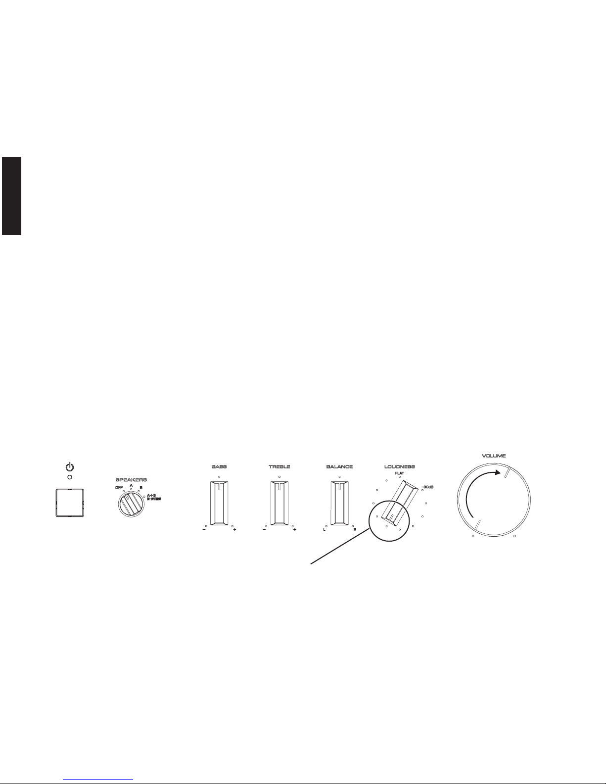
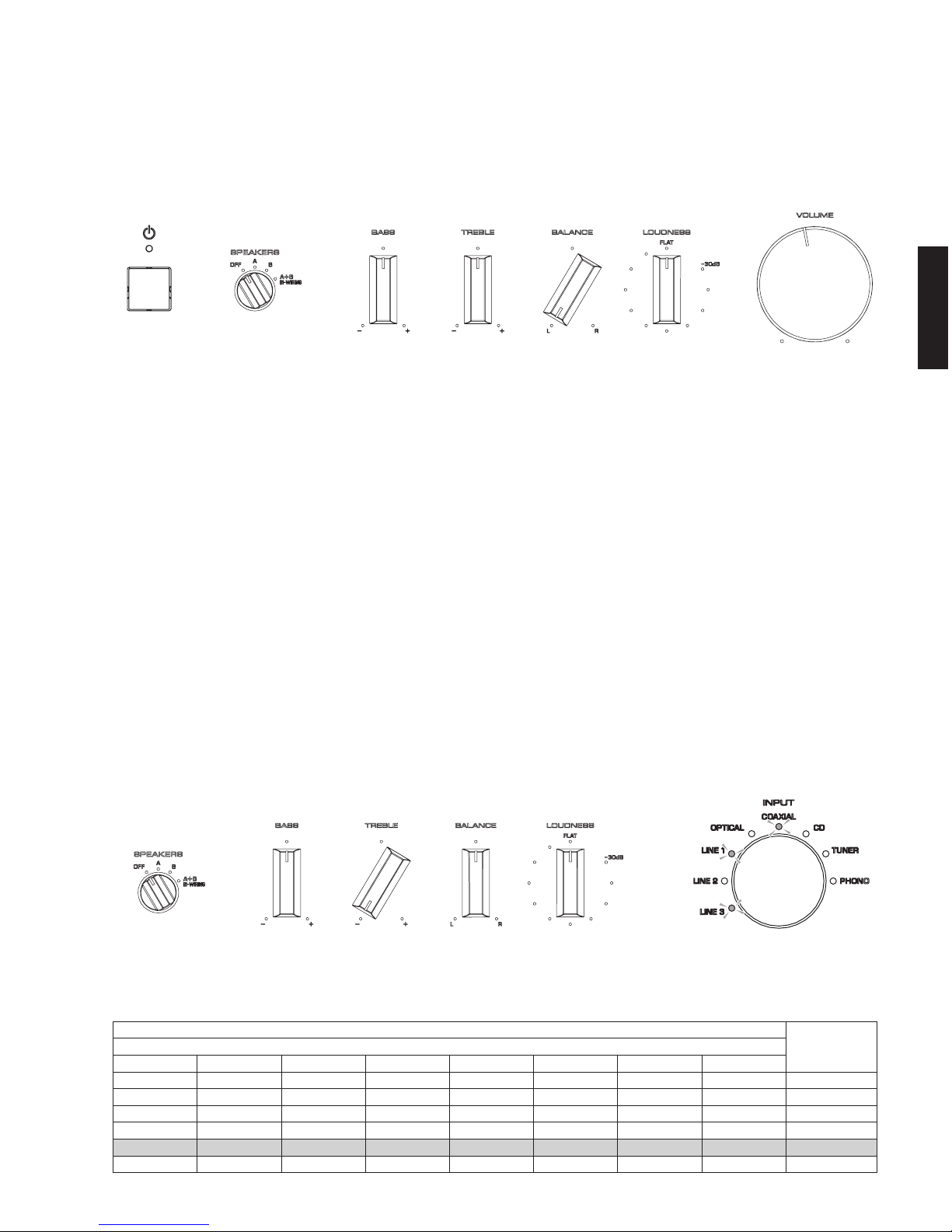
■ FRONT PANELS
A-S501
A-S301
A-S501
A-S301
4
A-S501/A-S301
A-S501/A-S301
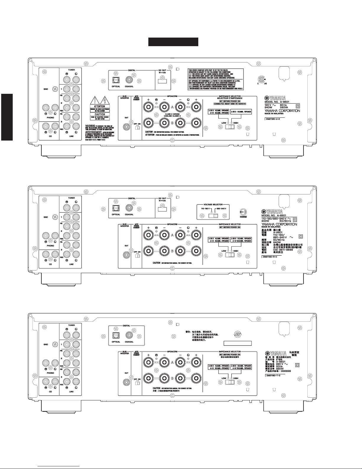
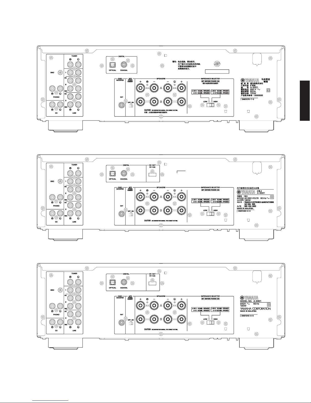
■ REAR PANELS
A-S501 (U model)
A-S501 (R model)
A-S501 (T model))
A-S501
5
A-S501/A-S301
A-S501/A-S301
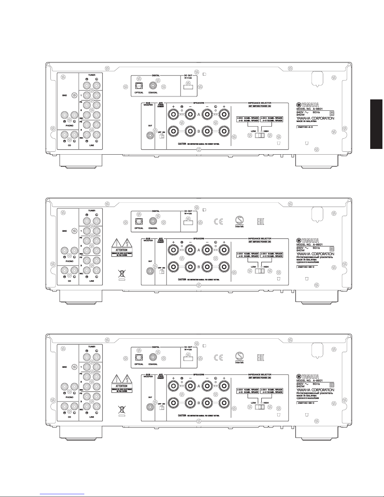
A-S501 (A model)
A-S501 (B, G models)
A-S501 (L model)
6
A-S501/A-S301
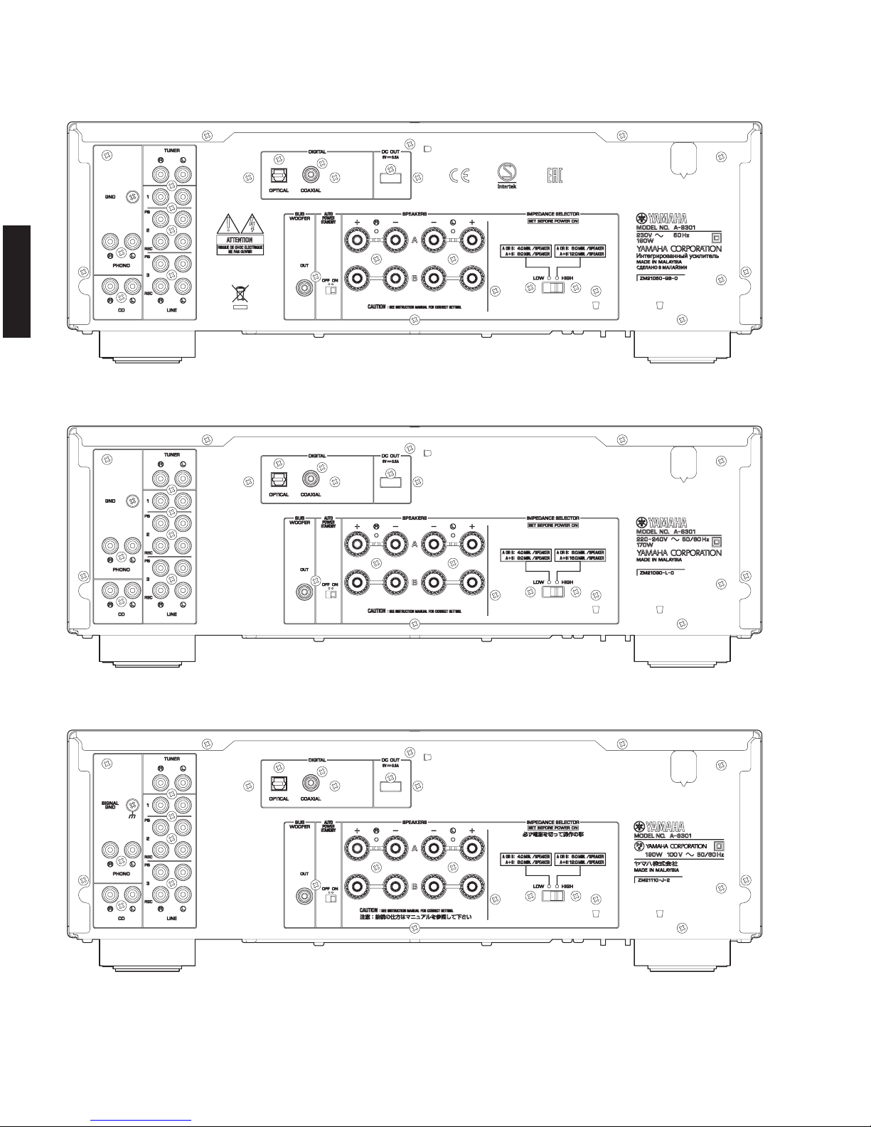
A-S501/A-S301
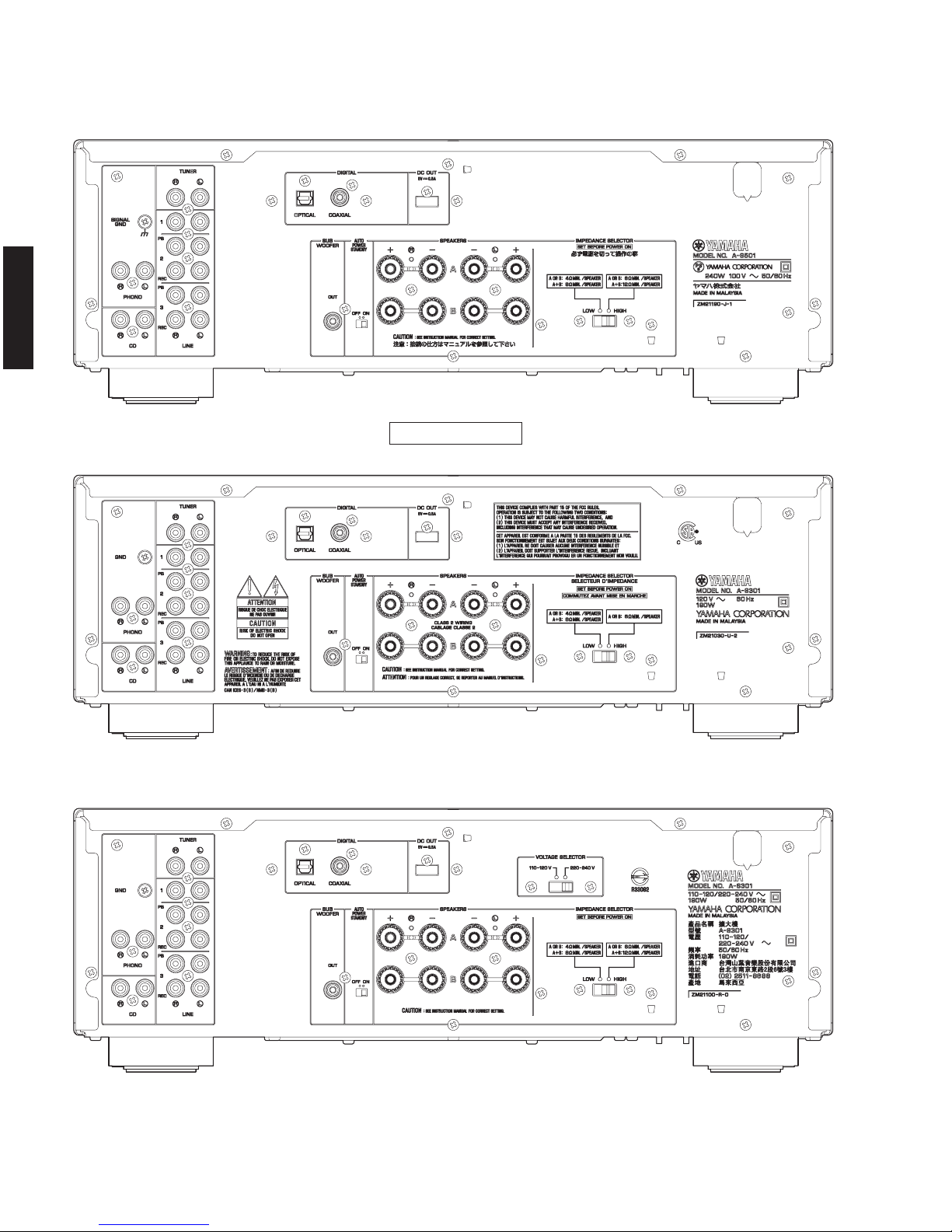
A-S501 (J model)
A-S301 (U model)
A-S301 (R model)
A-S301
7
A-S501/A-S301
A-S501/A-S301
A-S301 (T model)
A-S301 (K model)
A-S301 (A model)
8
A-S501/A-S301
A-S501/A-S301
A-S301 (B, G models)
A-S301 (L model)
A-S301 (J model)
9
A-S501/A-S301
A-S501/A-S301
■ SPECIFICATIONS / 参考仕様
■ Audio Section / オーディオ部
Minimum RMS Output Power (Power Amp. Section) /
定格出力(パワーアンプ部)
(8 ohms, 20 Hz to 20 kHz, 0.019 % THD)
[A‑S501] ...................................................................... 85W+85W
[A‑S301] ...................................................................... 60W+60W
(6 ohms, 20 Hz to 20 kHz, 0.038 % THD)
[A‑S501](U,R,A,B,G,Jmodels) ......................... 100 W + 100 W
[A‑S301](U,R,K,A,B,G,Jmodels) ......................... 70 W + 70 W
Dynamic Power Per Channel / ダイナミックパワー
(IHF)
(8 / 6 / 4 / 2 ohms)
[A‑S501] ...................................................... 130/150/185/220W
[A‑S301] ...................................................... 100/120/140/150W
MAX Power Per Channel
[B,Gmodels]
(1 kHz, 0.7 % THD, 4 ohms)
[A‑S501] ................................................................................. 120 W
[A‑S301] ................................................................................... 95W
IEC Power
[B,Gmodels]
(1 kHz, 0.019 % THD, 8 ohms)
[A‑S501] ................................................................................. 100 W
[A‑S301] ................................................................................... 75W
Power Band Width / パワーバンド
[A‑S501](0.04%THD,42.5W,8ohms) ............... 10Hzto50kHz
[A‑S301](0.04%THD,30W,8ohms) .................. 10Hzto50kHz
Damping
Factor / ダンピングファクター
(SPEAKER
‑A)
(1 kHz, 8 ohms)
[A‑S501] ........................................................................ 240 or more
[A‑S301] ........................................................................ 210 or more
Maximum Effective Output Power / 実用最大出力
(JEITA)
(1 kHz, 10 % THD)
[A‑S501]
R,L,Jmodels(8ohms) ....................................................130Wh
Jmodel(6ohms) ..............................................................150Wh
[A‑S301]
R,L,Jmodels(8ohms) ....................................................100 Wh
Jmodel(6ohms) ............................................................110 Whh
Input Sensitivity/Input Impedance / 入力感度/入力インピーダンス
PHONO(MM)
......................................................
3.0mV/47k‑ohms
CD, etc.
..............................................................
200mV/47k‑ohms
Maximum Input Signal / 最大許容入力
(1kHz)
PHONO (MM) (0.03 % THD) ........................................45 mV or more
CD, et
c. (0.5 % THD) .....................................................
2.2 V or more
Output Level/Output Impedance / 出力電圧/出力インピーダンス
REC OUT .............................................. 200 mV / 1.0 k‑ohms or less
Subwoofer OUT .....................................................3.5 V / 1.2 k‑ohms
(Cut off Frequency: 100 Hz)
Headphone Jack Rated Output/Impedance /
ヘッドホン出力/出力インピーダンス
CD, etc. (Input, 1 kHz
, 200 mV, 8 ohms)
[A
‑S501] ............................................................ 430mV/470ohms
[A‑S301] ............................................................ 360mV/470ohms
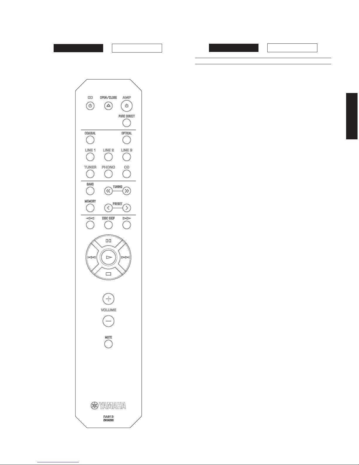
■ REMOTE CONTROL PANEL
RAS13
A-S301A-S501
A-S301A-S501
10
A-S501/A-S301
A-S501/A-S301
Standby Power Consumption / 待機時消費電力
................................................................................................... 0.5 W
Maximum Power Consumption
[Rmodel]
(1 kHz, 6 ohms, 10 % THD)
[A‑S501] ................................................................................. 510W
[A‑S301] ................................................................................. 430W
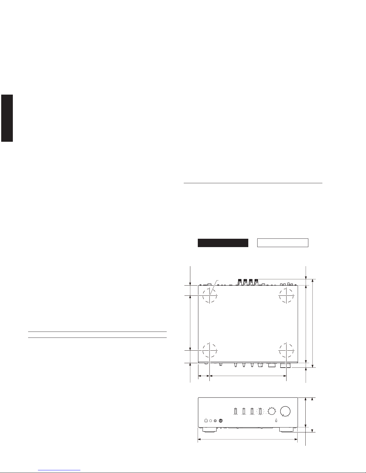
Dimensions (W x H x D) / 寸法(幅× 高さ× 奥行き)
....................................... 435 x 151 x 387 mm (17‑1/8" x 6" x 15‑1/4")
Weight / 質量
[A‑S501] ..............................................................
...10.3 kg (22.7 lbs.)
[
A‑S301] ...................................................................9.0 kg (19.8 lbs.)
Finish / 仕上げ
Blackcolor ..................................................U,R,A,B,G,Lmodels
Silvercolor .......................................... U,T,K,A,B,G,L,Jmodels
Accessories / 付属品
Remote control............................................................................... x 1
Battery(R6,AA,UM‑3) .................................................................. x 2
* Specifications are subject to change without notice.
※ 参考仕様および外観は、製品の改良のため予告なく変更すること
があります。
U ............................U.S.A. and
Canadian models
R .................... General model
T.....................Chinese model
K ......................Korean model
A .................Australian model
B .......................British model
G ................. European model
L................. Singapore model
J ...................Japanese model
• DIMENSIONS / 寸法図
Frequency Response / 再生周波数帯域
CD, etc. (20 Hz to 20 kHz) ...............................................0 ± 0.5 dB
CD, etc. Pure DIRECT ON (10 Hz to 100 kHz) ................0 ± 1.0 dB
RIAA Equalization Deviation / RIAA 偏差
PHONO (MM) .......................................................................... 0.5 dB
Total Harmonic Distortion / 全高調波歪率
(20Hzto20kHz)
PHONO (MM) to REC OUT (2.5 V) .........................
.... 0.03 % or less
[
A‑S501]
CD,etc.toSPOUT(45W,8ohms) ........................ 0.019 % or less
[A‑S301]
CD,etc.toSPOUT(30W,8ohms) ........................ 0.019 % or less
Signal to Noise Ratio / 信号対雑音比
(IHF‑ANetwork)
PHONO (MM) (5 mV Input shorted) ........................... 82 dB or more
CD, etc. (Pure DIRECT ON) (200 mV input shorted)
... 99dBormore
Residual Noise / 残留ノイズ
(IHF‑ANetwork)
................................................................................................ 40 μ V
Channel Separation / チャンネルセパレーション
CD, etc. (Input 5.1 k‑ohms shorted)
1kHz ......................................................................... 65dBormore
10 kHz
....................................................................... 50dBormore
Tone Control Characteristics / トーンコントロール特性
BASS
Boost/Cut
(20Hz)................................................................ ±10dB
Turnover frequency ...............................................................400Hz
TREBLE
Boost/Cut(20kHz) ............................................................... ±10dB
Turnover frequency ..............................................................3.5kHz
Continuous Loudness Control /
コンティニュアスラウドネスコントロール
Attenuation / 最大補正率 (1 kHz) ............................................. ‑30 dB
Supported Digital Audio Format (COAXIAL / OPTICAL) /
対応デジタルオーディオフォーマット (COAXIAL / OPTICAL)
................................................. 192 / 176.4 / 96 / 88.2 / 48 / 44.1 kHz
PCM Word Depth / 対応ビット長
...........
................................................................................. 16
/ 24 bit
Gain Tracking Error / GAIN トラッキングエラー
(0 to ‑99 dB) ..................................................................0.5 dB or less
■ General / 総合
Power Supply / 電源電圧
U model ....................................................................AC 120 V, 60 Hz
R model ........................................ AC 110–
120/220–240 V,
50/60 Hz
T model ..................................................................... AC 220 V, 50 Hz
K model ....................................................................AC 220 V, 60 Hz
A model ....................................................................AC 240 V, 50 Hz
B, G models .............................................................. AC 230 V, 50 Hz
L model ......
.................................................. AC 220–240 V
, 50/60 Hz
J model ................................................................AC 100 V, 50/60 Hz
Power Consumption / 消費電力
[A‑S501]
U,R,A,B,G,Jmodels .......................................................... 240 W
T, L models .............................................................................220 W
[A‑S301]
U,R,K,A,B,G,Jmodels......................................................190 W
T, L models .............................................................................170 W
A-S301A-S501
Top view
Unit: mm (inch)
単位:mm(インチ)
335 (13-1/4")50
(2")
20.5
(3/4")
25.5
(1")
387 (15-1/4")
341 (13-3/8")
55
(2-1/8")
46
(1-3/4")
240 (9-1/2")
ø 60
Front view
435 (17-1/8")
151 (5-7/8")
130 (5-1/8")
21
(7/8")
11
A-S501/A-S301
A-S501/A-S301
A-S301A-S501
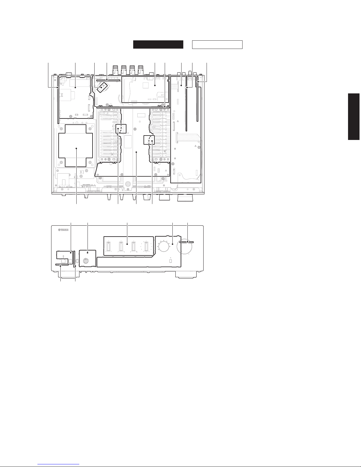
■ INTERNAL VIEW
■ SERVICE PRECAUTIONS / サービス時の注意事項
Safety measures
• Some internal parts in this product contain high
voltages and are dangerous. Be sure to take safety
measures during servicing, such as wearing insulating
gloves.
• Note that the capacitors indicated below are
dangerous even after the power is turned off because
an electric charge remains and a high voltage
continues to exist there.
B
efore starting any repair work, connect a discharging
r
esistor (5 k‑ohms/10 W) to the terminals of each
capacitor indicated below to discharge electricity.
The time required for discharging is about 30 seconds
per each.
C134, C135 on MAIN (1) P.C.B.
For details, refer to “PRINTED CIRCUIT BOARDS:
MAIN (1) P.C.B.”.
安全対策
• この製品の内部には高電圧部分があり危険です。修理
の際は、絶縁性の手袋を使用するなどの安全対策を行っ
てください。
• 下記のコンデンサには電源を OFF にした後も電荷が残
り、高電圧が維持されており危険です。
修理作業前に放電用抵抗(
5 k Ω /10 W)を下記の各コ
ンデンサの端子間に接続して放電してください。
放電所用時間は各々約 30 秒間です。
MAIN(1)P.C.B. の C134、C135
詳しくは “PRINTED CIRCUIT BOARDS:MAIN(1)
P.C.B.” を参照してください。
a
MAIN (8)
b
MAIN (2)
c
FUNCTION (4)
d
MAIN (3) (R model)
e
DIGITAL
f
MAIN (6)
g
FUNCTION (1)
h
FUNCTION (2)
i
FUNCTION (3)
j
MAIN (5)
k
MAIN (1)
l
MAIN (4)
m
POWER TRANSFORMER
n
OPERATION (7)
o
OPERATION (4)
p
OPERATION (3)
q
OPERATION (1)
r
OPERATION (2)
s
OPERATION (6)
t
OPERATION (5)
Top view
Front view
1 3 8 92
n o p q
4 5 6 7
st
k jlm
r
12
A-S501/A-S301
A-S501/A-S301
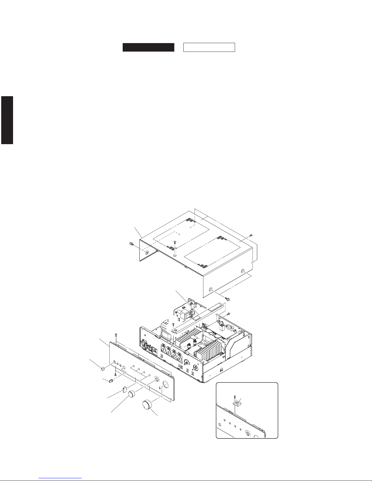
■ DISASSEMBLY PROCEDURES / 分解手順
(Remove parts in the order as numbered.)
Disconnect the power cable from the AC outlet.
1. Removal of Top Cover
a. Remove 4 screws (1), 4 screws (2) and screw (3).
(Fig. 1)
b. Remove the top cover. (Fig. 1)
2. Removal of Front Panel Unit
a. (A‑S501)
Remove screw ( ④ ), screw ( ⑤ ) and then remove
the top frame.(Fig. 1)
(A‑S301)
Remove screw ( ⑥ ) and then remove the top
support.
(Fig. 1)
b.
Pull out the knobs and cap. (Fig. 1)
c. Remove 7 screws ( ⑦ ). (Fig. 1)
d. Remove the front panel unit. (Fig. 1)
(番号順に部品を外してください。)
AC 電源コンセントから、電源コードを抜いてください。
1. トップカバーの外し方
a. 1のネジ 4 本、2のネジ 4 本、3のネジ 1 本を外し
ます。(Fig. 1)
b. トップカバーを取り外します。(Fig. 1)
2. フロントパネルユニットの外し方
a. (A‑S501)
④ のネジ 1 本、⑤ のネジ 1 本を外し、トップフレー
ムを取り外します。(Fig. 1)
(A‑S301)
⑥ のネジ 1 本を外し、トップサポートを取り外しま
す。(Fig. 1)
b. ツマミ、キャップを取り外します。(Fig. 1)
c. ⑦ のネジ 7 本を外します。
(Fig. 1)
d. フロントパネルユニットを前方へ取り外します。
(Fig. 1)
Fig. 1
Front panel unit
フロントパネルユニット
Knob VOLUME
ツマミVOLUME
Knob INPUT
ツマミ INPUT
Knob BASS/TREBLE/BAL./LOUD.
ツマミBASS/TREBLE/BAL./LOUD.
Knob SPEAKERS OFF/A/B/A+B
ツマミSPEAKERS OFF/A/B/A+B
Cap POWER
キャップPOWER
⑦
⑦
Top frame
トップフレーム
(A-S501)
①
④
⑤
⑥
トップサポート
(A-S301)
Top cover
トップカバー
①
②
③
Topsupport
A-S301A-S501
13
A-S501/A-S301
A-S501/A-S301
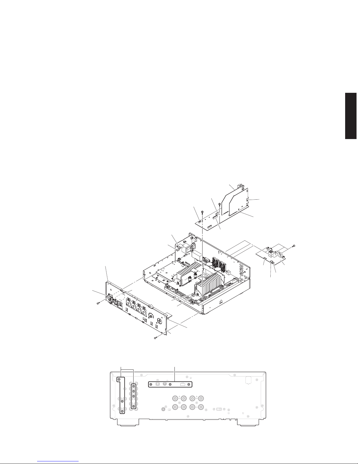
⑩
Sub-chassis unit
サブシャーシユニット
Hook
フック
CB706
CB101
CB105
Hook
フック
CB853
⑧
⑧
CB2
CB21
FUNCTION (1) P.C.B.
FUNCTION (2) P.C.B.
FUNCTION (3) P.C.B.
CB506
CB505
DIGITAL P.C.B.
⑫
⑬
CB508
CB304
CB301
CB303
⑪ ⑨
3. Removal of Sub-chassis Unit
a. Remove 2 screws ( ⑧ ). (Fig. 2)
b. Remove CB505, CB508, CB706 and CB853. (Fig. 2)
c.
Release 2 hooks and then remove the sub‑chassis unit.
(Fig. 2)
4. Removal of DIGITAL P.C.B.
a. Remove 3 screws (9). (Fig. 3)
b. Remove 3 screws (j). (Fig. 2)
c.
Remove CB21, CB301, CB303 and CB304
and then
remove the DIGITAL P.C.B
. (Fig. 2)
5. Removal of DIGITAL P.C.B.
a. Remove 7 screws (k). (Fig. 3)
b. Remove screw (l) and screw (m). (Fig. 2)
c.
Remove CB2, CB101, CB105 and CB404
and then
remove the FUNCTION (1)–(3) P.C.B
. (Fig. 2)
3. サブシャーシユニットの外し方
a. ⑧ のネジ 2 本を外します。(Fig. 2)
b. CB505、CB508、CB706、CB853 を外します。(Fig. 2)
c.
フック 2 箇所を外し、サブシャーシユニットを取り外
します。(Fig. 2)
4. DIGITAL P.C.B. の外し方
a. 9のネジ 3 本を外します。(Fig. 3)
b. jのネジ 3 本を外します。(Fig. 2)
c.
CB21、CB301、CB303、CB304 を外し
、DIGITAL P.C.B.
を外します。(Fig. 2)
5. FUNCTION (1) ~ (3) P.C.B. の外し方
a. kのネジ 7 本を外します。(Fig. 3)
b. lのネジ 1 本、mのネジ 1 本を外します。(Fig. 2)
c.
CB2、CB101、CB105、CB404 を外し、
FUNCTION (1)
〜 (3) P.C.B. を一緒に取り外します。(Fig. 2)
Fig. 2
Fig. 3
14
A-S501/A-S301
A-S501/A-S301
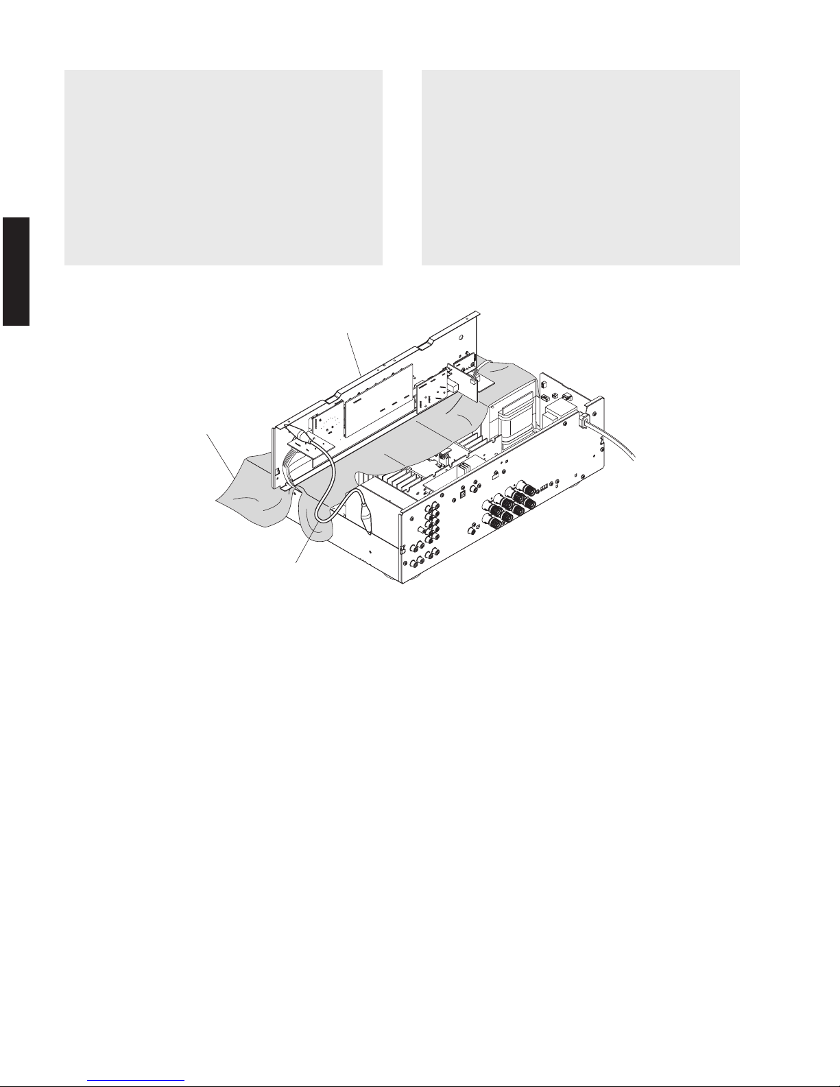
Grou
Su
Ru
nd lead
アース線
b-chassis unit
サブシャーシユニット
bber sheet and cloth
ゴムシートと布
When checking the P.C.B.s:
• Put the rubber sheet and the cloth over this unit, Then
place the sub‑chassis unit on the cloth and check it.
(Fig. 4)
• Connect the ground point of the sub‑chassis unit to
the chassis with a ground lead or the like. (Fig. 4)
• Reconnect all cables (connectors) that have been
disconnected.
• When connecting the flexible flat cable, be careful
with polarity.
P.C.B. をチェックする場合には:
• 本機の上にゴムシートと布を敷き、その上にサブ
シャーシユニットを置いてチェックします。(Fig. 4)
• サブシャーシユニットのアースをリード線等で
シャーシに接続してください。(Fig. 4)
• 外したケーブル(コネクター)をすべて接続します。
• フラットケーブルを接続する際、極性に注意してく
ださい。
Fig. 4

15
A-S501/A-S301
A-S501/A-S301
■ UPDATING FIRMWARE / ファームウェアのアップデート
When the following parts are replaced, the firmware must
be updated to the latest version.
FUNCTION P.C.B.
● Confirmation of firmware version
Before and after updating the firmware, check the
firmware version by using the self‑diagnostic function
menu.
Start up the self‑diagnostic function, have the
firmware version indicated, and note them down.
(For details, refer to
“SELF‑DIAGNOSTIC FUNCTION”)
*
When the firmware version is different from
written one after updating, perform the updating
procedure again from the beginning.
● Factory preset
After updating the firmware, revert to factory presets
with the following procedure to properly store the
setup information.
Start up the self‑diagnostic function.
(For details, refer to “SELF‑DIAGNOSTIC FUNCTION”)
Set the “SPEAKERS
” selector to the “A” position,
pr
ess the “z” (power) switch to turn off the power
once and press the “z” (power) switch to turn on the
power again.
Then the factory preset is performed.
● Required Tools
• CD, DVD or BD player (with DIGITAL OUTPUT
(OPTICAL or COAXIAL) jack)
• Optical cable (when OPTICAL jack is used)
• Digital audio pin cable
(when COAXIAL jack is used)
• Firmware CD
Download the lates
t firmware from the specified
download sour
ce and create the firmware CD.
下記の部品を交換した場合、ファームウェアを最新バー
ジョンにアップデートする必要があります。
FUNCTION P.C.B.
● ファームウェアのバージョンの確認
ファームウェアのアップデートの前後に、ファーム
ウェアのバージョンをダイアグで確認します。
ダイアグを起動してファームウェアのバージョンを
表示し、それらを書きとめます。
(詳細は「ダイアグ」 を参照してください。)
※ アップデート後、ファームウェアのバージョンが
書き込まれたものと異なる場合、ファームウェア
のアップデートを最初からやり直してください。
● ファクトリープリセット
ファームウェアのアップデート後、設定情報を正常に
記憶するために、下記の方法でファクトリープリセッ
トする必要があります。
本機のダイアグを
起動します。
(詳細は「ダイアグ」
を参照してください。)
“SPEAKERS” セレクターを “A” の位置にして、“z”
(電源)スイッチを押して電源をいったん切り、再び
“z”(電源)スイッチを押して電源を入れるとファク
トリープリセットされます。
● 必要なツール
・ CD、DVD または BD プレーヤー(DIGITAL
OUTPUT(OPTICAL または COAXIAL)端子付き)
・ 光ファイバーケーブル(OPTICAL 端子使用時)
・
デジタル音声ピンケーブル(COAXIAL 端子使用時)
・ ファームウェア CD
指定のダウンロード先から最新のファームウェア
をダウンロードして、ファームウェア CD を製作
してください。
A-S301A-S501
* The following models can be used as a tool to update the firmware.
下記のモデルはファームウェアのアップデート用に使えます。
CD player: CD-C600/CD-S1000/CD-S2000/CD-S300/CD-S700/CDX-496/CDX-596/CDX-890
DVD player: DV-C6760/DVD-840/DVD-C740/DVD-C750/DVD-C940/DVD-C950/DVD-CX1/DVD-S1200/
DVD-S1800/DVD-S2300(MKII)/DVD-S2700/DVD-S30/DVD-S510/DVD-S520/DVD-S530/
DVD-S540/DVD-S550/DVD-S657/DVD-S700/DVD-S80/DVD-S840
BD (Blu-ray) playe
r: BD-940/BD-S1065/BD-S1900/BD-S2900/BD-S671
Other
s: CDR-D651/CDR-HD100
16
A-S501/A-S301
A-S501/A-S301
● Connection
Use the optical cable (when OPTICAL jack is used)
or Digital audio pin cable (when COAXIAL jack is
used) to connect the CD, DVD or BD player and the
unit.
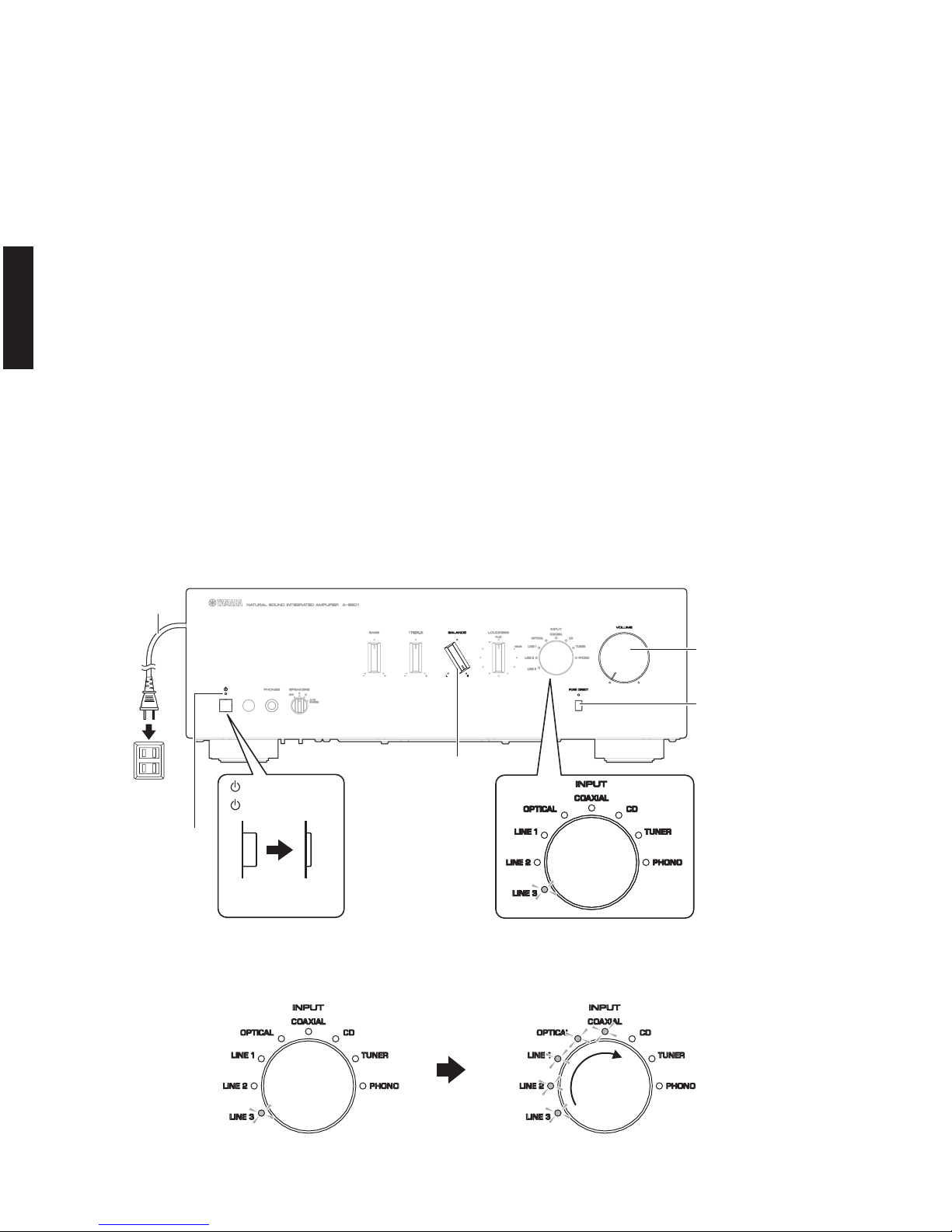
● Operation Procedures
1. Set this unit to the firmware update mode.
a. Connect the power cable of this unit to the AC
outlet. (Fig.1)
b. Set the “z” (power) switch to the OFF position.
(Fig.1)
c. Fully turn the “BALANCE” knob to the rig
ht (R).
(Fig.1)
d.
Fully turn the “VOLUME” knob to the left
(minimum). (Fig.1)
e While pressing the “PURE DIRECT” switch, press
the “z” (power) switch to turn on this unit. (Fig.1)
The unit is set to the firmware update mode.
When this unit is set to the firmware update mode, the
power indicator flashes at a 1‑second interval.
When this unit is set to the firmware update mode
, the
“
LINE3” indicator light up.
(Fig. 2)
2. Play the firmware CD on the CD/DVD/BD player.
Updating of the firmware starts automatically. (Fig. 3)
● 接続
光ファイバーケーブル(OPTICAL 端子使用時)、デジ
タル音声ピンケーブル(COAXIAL 端子使用時)を使
用して、CD、DVD または BD プレーヤーと本体を接
続します。
● 操作手順
1. ファームウェアアップデートモードに設定します。
a. 電源コードを AC コンセントに接続します。(Fig.1)
b. “z”(電源)スイッチを押してオフにします。(Fig.1)
c. “BALANCE”ツマミを右(R)いっぱいまで回します。
(Fig.1)
d. “VOLUME” ツマミを左(最少)いっぱいまで回し
ます。(Fig.1)
e. “PURE DIRECT” スイッチを押しなが
ら本体の “z
”
(電源)スイッチを押して電源を入れます。(Fig.1)
ファームウェアアップデートモードに入ります。
ファームウェアアップデートモードに入ると、パワー
インジケーターが1秒間隔で点滅します。
ファームウェアアップデートモードに入ると、“LINE3
”
インジケーターが点灯します。(Fig.2)
2. CD/DVD/BD プレーヤーでファームウェア CD を再生
します。 ファームウェアのアップデートが自動的に開
始されます。(Fig.3)
Updating started
アップデート開始
Updating
アップデート中
Fig. 3
"PURE DIRECT" switch
“PURE DIRECT” スイッチ
"VOLUME" knob
“VOLUME” ツマミ
"BALANCE" knob
“BALANCE” ツマミ
Power indicator
パワーインジケーター
" " (Power) switch
OFF ON/
STANDBY
“”(電源)スイッチ
Fig. 1
Fig. 2
Power cable
電源コード
AC outlet
ACコンセント
17
A-S501/A-S301
A-S501/A-S301
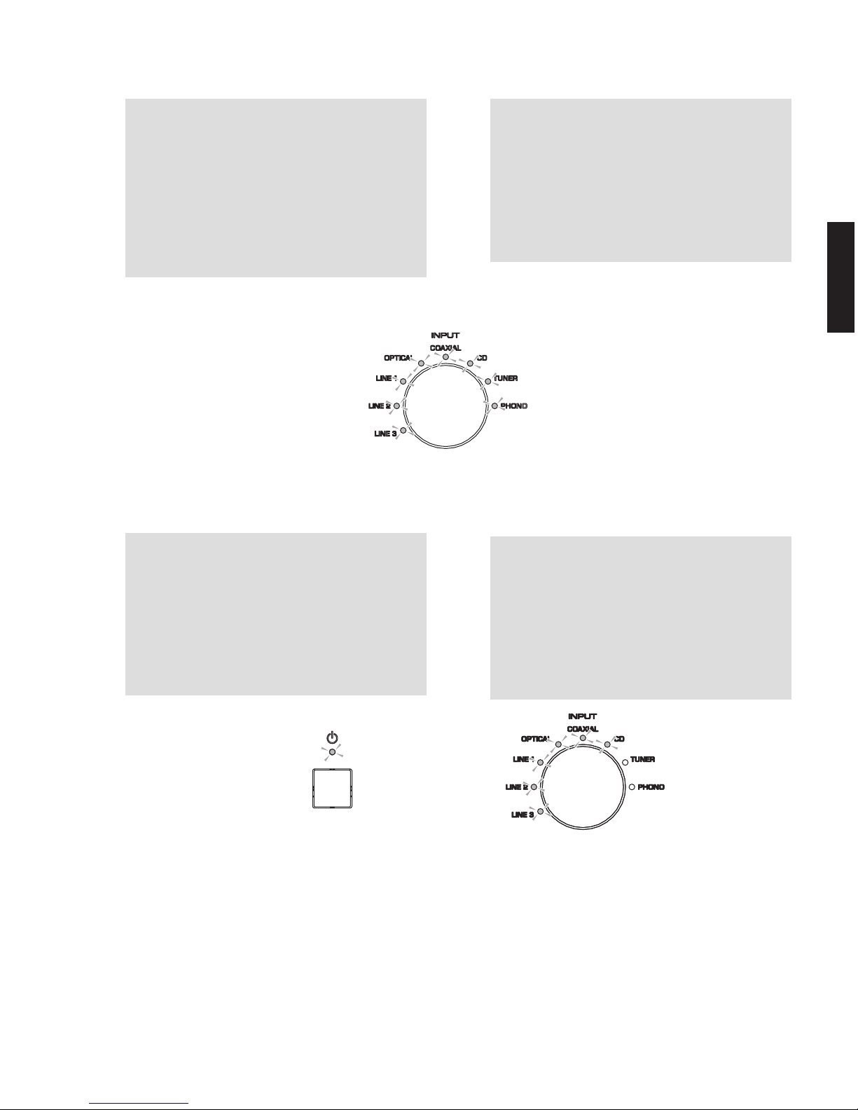
Note:
•
Ifthelightingpatternofthe“INPUT”indicators
does not change 10 seconds or more after
playback of the firmware CD was started, try
updating the firmware again, starting from the
beginning of the procedure.
•
Becarefulthatthepowercableisnotunplugged
and the power voltage does not drop while the
firmware is being updated. Otherwise, firmware
updating may fail and cannot be performed
again.
3. After the firmware has been updated, all “INPUT”
indicators light up. (Fig. 4)
After checking that all “INPUT” indicators light up,
press the “z” (power) switch to turn it off, then on
again.
Note:
If the power indicator flashes at a 0.5‑second
interval or all “INPUT” indicators do not light up after
updating the firmware, try updating the firmware
again, starting from the beginning of the procedure.
(Fig. 5)
These indicate that the data was not correctly
written to the microprocessor. If the same result is
obtained after trying to update the firmware again,
the microprocessor may be damage
d.
4.
Press the “z” (power) switch to turn off the power.
5. Eject the firmware CD from the CD/DVD/BD player.
6. Start up the self‑diagnostic function and check that
the firmware version is the same as written one.
(For details, refer to “Indication of firmware version”.)
7. Revert to factory presets.
(For details, refer to “Factory Preset”.)
注意:
• ファームウェア CD の再生を開始してから 10 秒
以上経過しても、“INPUT” インジケーターの点灯
状況が変化しない場合は、ファームウェアのアッ
プデートを最初からやり直してください。
• ファームウェアのアップデート中、AC コードを
抜いたり、電源電圧を降下させたりしないように
注意してください。ファームウェアの書き込みに
失敗して、再度書き込みができなくなる可能性が
あります。
3. ファームウェアのアップデート完了後、“INPUT” イン
ジケーターがすべて点灯します。(Fig. 4)
“INPUT” インジケーター全ての点灯を確認したら、
“z”(電源)スイッチを OFF から ON にして、もう
一度電源を入れます。
注意:
ファームウェアのアップデート完了後、パワーイン
ジケーターが 0.5 秒間隔で点滅している状態、また
は “INPUT” インジケーターが全て点灯しない状態の
場合には、ファームウェアの書き込みを最初からや
り直してください。(Fig. 5)
この場合、マイコン に正しくデータが書込めなかっ
たことを示しています。ファームウェアの書き込み
をやり直しても同じ結果になる場合は、マイコンが
壊れている可能性があります。
4. “z”(電源)スイッチを押して電源を切ります。
5. CD/DVD/BD プレーヤーからファームウェア CD を取
り出します。
6. ファームウェアのバージョンを確認します。
ダイアグを起動し、ファームウェアのバージョンが、
書き込まれたものと同じであることを確認します。
(詳細は、ダイアグの “ ファームウェアのバージョン
表示 ” を参照してください。)
7. ファクトリープリセットを行います。
(詳細は、ダ
イアグの “ ファクトリープリセット
” を
参照してください。)
Fig. 5
Update is completed
アップデート完了
Fig. 4
18
A-S501/A-S301
A-S501/A-S301
■ SELF-DIAGNOSTIC FUNCTION / ダイアグ(自己診断機能)
This unit has self‑diagnostic functions that provides the
following functions.
• Indication of firmware version
• Indication of “AUTO POWER STANDBY” switch status
• Indication and checking of protection information
• Factory preset
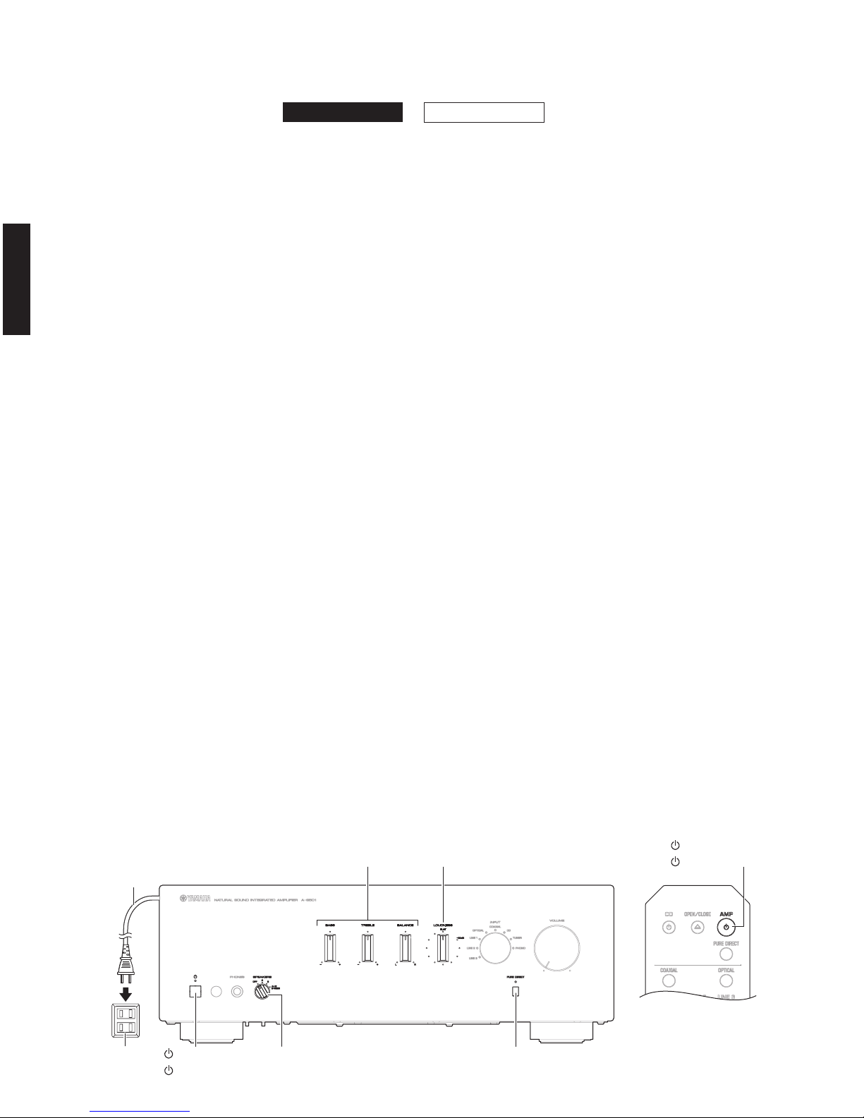
● Starting Self-Diagnostic Function
1. Press the “z” (power) switch to turn off this unit. (Fig. 1)
2. Connect the power cable of this unit to the AC outlet.
(Fig. 1)
3. Set the “SPEAKERS” knob to the “OFF” position. (Fig. 1)
Note:
Since factory preset is reserved by turning
off this unit when the “SPEAKERS” knob is set
to the “A” position, set the “SPEAKERS” knob
to the “OFF” position before starting the self‑
diagnostic function mode
.
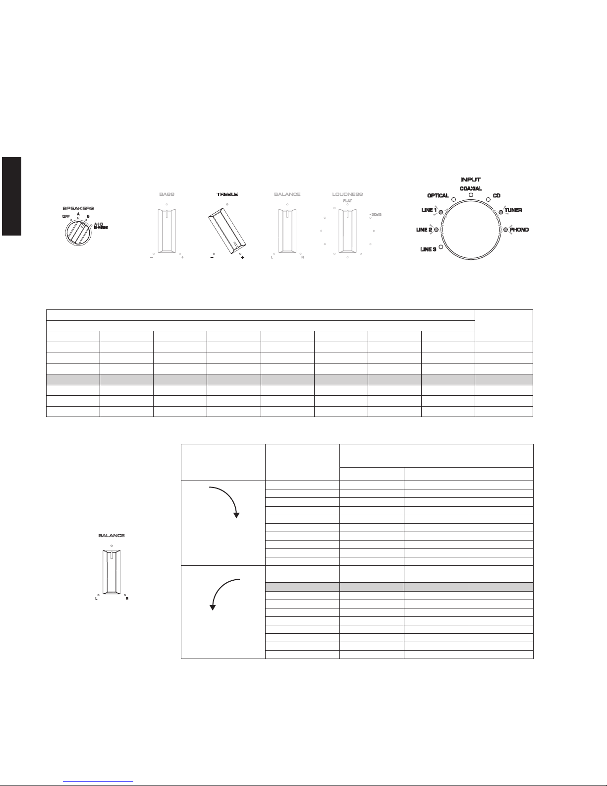
4. Set the “BASS”, “TREBLE” and “BALANCE” knobs to
the top positions. (Fig. 1)
Note:
Be sure to set the “BASS”, “TREBLE” and
“BALANCE” knobs to the top positions. These
positions are stored when the self‑diagnostic
function mode is started, and software corrections
are made to the top position for each selector.
In addition, the self diagnostic function mode
cannot be started if the top positions for the
knobs are off by more than ± 5% of the 2.5 V
input voltage.
5. Set the “LOUDNESS” knob to the “FLAT”
position. (Fig. 1)
6. Press the “z” (power) key to turn on this unit. (Fig. 1)
7. Press the “z” (AMP) key on the remote control to set
this unit to standby. (Fig. 2)
8. Repeat pressing the “PURE DIRECT” key 6 times
within 15 seconds. (Fig. 1)
9. Press the “z” (AMP) key on the remote control to turn
on this unit. (Fig. 2)
This unit starts the self‑diagnostic function mode.
本機には下記の機能をもつダイアグ(自己診断機能)が
あります。
• ファームウェアのバージョン表示
•
“AUTO POWER STANDBY” スイッチの状態表示
• プロテクション情報の表示と確認
• ファクトリープリセット
● ダイアグの起動
1. 本機の “z”(電源)スイッチを OFF にします。(Fig.1)
2. 電源コードを AC コンセントに接続します。(Fig.1)
3. “SPEAKERS” ツマミを “OFF” にします。(Fig.1)
注意: “SPEAKERS” ツマミを “A” の位置で電源を切
るとファクトリープリセットが予約されるた
め、ダイアグの起動時に “SPEAKERS” ツマミ
を “OFF” の位置にします。
4. “BASS”、“TREBLE”、“BALANCE” ツマミを中央の位
置に合わせます。 (Fig.1)
注意: “BASS”、“TREBLE”、“BALANCE” ツマミは必ず
中央の位置に合わせてください。ダイアグ起動
時この位置を記憶して各ツマミの中央位置の補
正をソフ
ト的に行っています。
また、各ツマミの中央位置が入力電圧 2.
5V の
± 5%以上外れている場合にはダイアグが起動
できません。
5. “LOUDNESS” ツマミを “FLAT” の位置に合わせます。
(Fig.1)
6. 本機の “z”(電源)スイッチを ON にします。(Fig.1)
7. リモコンの “z”(AMP)キーを押して、本機をスタ
ンバイの状態にします。(Fig.2)
8. 15 秒以内に “PURE DIRECT” キーを 6 回押します。
(Fig.1)
9. リモコンの “z”(AMP)キーを押して電源を入れます。
(Fig.2)
ダイアグが起動します。
A-S301A-S501
Keys of this unit / 本機キー
Key on Remote control /
リモコンキー
“PURE DIRECT” key
“PURE DIRECT” キー
“BASS” , “TREBLE” , “BALANCE” knobs
“BASS” 、 “TREBLE” 、 “BALANCE” ツマミ
“LOUDNESS” knob
“LOUDNESS” ツマミ
“” (Power) switch “SPEAKERS” knob
“”(電源)スイッチ
“”
(AMP) key
“”(AMP)キー
“SPEAKERS” ツマミ
Power cable
電源コード
AC outlet
ACコンセント
Fig. 1 Fig. 2
19
A-S501/A-S301
A-S501/A-S301
● Display provided when Self-Diagnostic
Function started
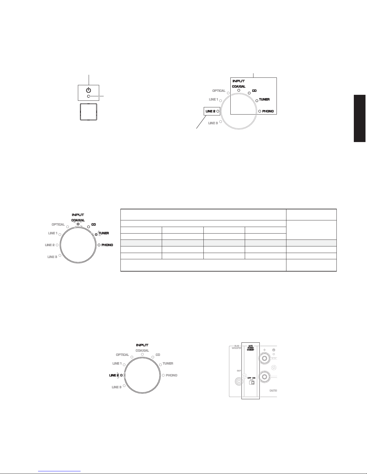
● Details of Indication
• Indication of firmware version
The firmware version of the microprocessor (IC502
of the FUNCTION P.C.B.) is indicated in the binary
code (BCD) using the “COAXIAL”, “CD”, “TUNER” and
“PHONO” indicators. (Fig. 4)
• Indication of AUTO POWER STANDBY switch
status
The status (ON/OFF) of the “AUTO POWER STANDBY”
switch located on the rear panel is indicated using the
“
LINE 2 INPUT” indicator. (Fig. 5)
Light up
:“AUTO POWER STANDBY” switch is “ON”
Off: “AUTO POWER STANDBY” switch is “OFF”
● ダイアグ起動時の表示
● 表示の詳細
• ファームウェアのバージョン表示
マイコン(FUNCTION P.C.B. の IC502)のファームウェ
アバージョンが “COAXIAL”、“CD”、“TUNER”、“PHONO”
インジケーターを使って2 進数(BCD)で表示されます。
(Fig. 4)
• AUTO POWER STANDBY スイッチの状態表示
リアパネルにある “AUTO POWER STANDBY” スイッチの
状態(ON/OFF)が “LINE 2 INPUT” インジケーターを使っ
て表示されます。
(Fig. 5)
点灯: “AUTO POWER STANDBY” スイッチ “ON”
消灯: “AUTO POWER STANDBY” スイッチ “OFF”
Fig. 5
・ Indication of firmware version
ファームウェアのバージョン表示
・ Indication of auto power standby status
オートパワースタンバイの状態表示
・ Indication of protection information
プロテクション情報の表示
Power indicator
パワーインジケーター
INPUT indicators
INPUTインジケーター
Fig. 3
INPUT indicators / INPUT インジケーター
Firmware version /
ファームウェアバージョン
Binary number (BCD) [Lightup: 1, Off: 0] / 2進数(BCD)
[点灯:1、消灯:0]
Decimal number
/ 10進数
COAXIAL CD TUNER PHONO
(2 = 8)
3
(2 = 4)
2
(2 = 2)
1
(2 = 1)
0
0 V0010 (8+2=10)
V0011 (8+2+1=11)
V0012 (8+4=12)
101
1101
0011
•
•
•
•
•
•
Fig. 4

20
A-S501/A-S301
A-S501/A-S301
• Indication of protection information
The protection information is indicated by the flashing
pattern of the “z”(power) indicator.
PS (Power Supply) protection
Cause: The voltage in the power supply
section is abnormal.
Normal value: 2.559 to 3.259V (AD value: 130‑167)
Detection port: PRV (FUNCTION (1) P.C.B. 93 pin of
the microprocessor IC502)
Detected at: ACL, ± 15, +5S
I protection L/Rch
Cause: Excess curre
nt flow into amplifier.
Speaker ter
minal shorted. (*)
Normal value: LOW (0V)
Detection port: PRI (FUNCTION (1) P.C.B. 69 pin
of the microprocessor IC502)
Detected at: PRI (Amplifier output L/Rch of
MAIN (1) P.C.B.)
* If the protection function works due to shortage
at the speaker terminal, the power turns off at the
excess current protection L/Rch.
However, pressing the “z” (power) switch for OFF/
ON, all “IN
PUT” indicators flash 5 times and the
power to tur
n on.
DC voltage protection
Cause: Abnormal DC voltage of amplifier
output.
Normal value: 0.947 to 2.517V (AD value: 48‑129)
Detection port: PRD (FUNCTION (1) P.C.B. 89 pin
of the microprocessor IC502)
Detected at: Amplifier output L/Rch of MAIN (1)
P.C.B.
• プロテクション情報の表示
“z” ( パワー ) インジケーターの点滅パターンにより、
プロテクション情報を表示します。
電源電圧プロテクション
原因: 電源部の電圧が異常。
正常値: 2.559 〜 3.259V (AD 値:130‑167)
検出ポート: PR
V(FUNCTION (1) P.C.B. マイコ
ン IC502 の 93 ピン)
検出先: ACL、± 15、+5S
過電流プロテクション L/Rch
原因: アンプ部に過電流が流れた。
スピーカー端子をショートした。(※)
正常値: LOW(0V)
検出ポート: PRI(FUNCTION (1) P.C.B.:マイコ
ン IC502 の 69 ピン)
検出先: PRI(MAIN (1) P.C.B. のアンプ出力
L/Rch)
※ スピーカー端子のショートでプロテクションが働
いた場合、過電流プロテクション L/Rch で電源を
切ります。ただし “z”(電源)スイッチを OFF/
ON すると、すべての “INPUT” インジケーターが
5 回点滅して電源が入ります。
DC 電圧プロテクション
原因: アンプ出力の DC 電圧が異常。
正常値: 0.947 〜 2.517V (AD 値:48‑129)
検出ポート: PRD(
FUNCTION (1) P.C.
B.:マイコ
ン IC502 の 89 ピン)
検出先: MAIN (1) P.C.B. のアンプ出力 L/Rch
Power indicator flashing pattern /
パワーインジケーターの点滅パターン
Flashing 2 /
点滅2
Flashing 3 /
点滅3
Flashing 4 /
点滅4
Flashing 6 /
点滅6
Flashing 7 /
点滅7
Lit up/
点灯
: Lit / 点灯
: Off / 消灯
500mS 500mS 500mS 1000mS 500mS 500mS 500mS 500mS
Continuous / 連続
Types of protection function /
プロテクションの種類
PS protection /
電源電圧プロテクション
I protection L/R ch /
過電流プロテクション L/R ch
DC protection /
DC電圧プロテクション
THM protection L/R ch /
THM
(温度)
プロテクションL/R ch
Diode THM protection /
ダイオードTHM(温度)プロテクション
No protection function /
プロテクション無し
Flashing 5 /
点滅5
USB OC protection /
USB OCプロテクション
(U,R,K,A,B,G,L,J models)
1000mS
1000mS
500mS 500mS 500mS 500mS 500mS 500mS 500mS 500mS 500mS 500mS 500mS 500mS
500mS 500mS 500mS 500mS 500mS 500mS 500mS 500mS 500mS 500mS 500mS
500mS 500mS 500mS 500mS 500mS 500mS 500mS 500mS 500mS
500mS 500mS 500mS 500mS
500mS 500mS 500mS 500mS 500mS 500mS 500mS 500mS 500mS
1000mS
1000mS
1000mS
500mS
1000mS
500mS 500mS 500mS 500mS 500mS
Fig. 6

21
A-S501/A-S301
A-S501/A-S301
USB OC (Over Current) protection
(U, R, K, A, B, G, L models)
Cause: USB power supply is overcurrent.
Normal value: HIGH (5V)
Detection port: USB_N_OCPRT (FUNCTION (1)
P.C.B. 45 pin of the microprocessor
IC502)
Detected at: USB_OCPRT (IC309 of DIGITAL
P.C.B.)
THM protection L/Rch
Cause: Abnormal temperature of heat sink.
Normal value:
A‑S501: 0.20 to 1.80V (AD value: 10‑91)
A‑S301: 0.20 to 1.66V (AD value: 10‑85)
Detection port: THM1 (FUNCTION (1) P.C.B. 84 pin of
the microprocessor IC502)
THM2 (FUNCTION (1) P.C.B. 83 pin of
the microprocessor IC502)
Detected at:
THML (Heat sink temperature detection
Lch IC101 of the MAIN (4) P.C.B.)
THMR (Heat sink temperature detection
Rch IC102 of the MAIN (5) P.C.B.)
Diode THM protection
Cause: Abnormal temperature of diode (D111
of MAIN (1) P.C.B).
Normal value: 0 to 0.346V (AD value: 0‑18)
Detection por
t: THM3 (FUNCTION (1) P.C.B. 97 pin of
the microprocessor IC502)
Detected at: THM3 (TH501 of FUNCTION (4) P.C.B.,
D111 of MAIN (1) P.C.B.)
• Checking of protection information
Check the following information when a protection
function has been activated.
・ Protection history (up to 4)
・ Position of “VOLUME” knob when the protection
function was activated (*)
・ AD value when t
he protection function was
activated
・ AD value when the diode THM protection function
was activated
・ Operating information for the speaker relay/
headphones relay
・ AD value for the “BALANCE” knob
・ Input source information
* Since the “VOLUME” knob automatically moves
to the position when the protection function was
activated, do not to operate any other knob while
the “VOLUME” knob is moving.
USB 過電流プ
ロテクション
原因: U
SB 供給電源の過電流。
正常値: HIGH (5V)
検出ポート: USB_N_OCPRT (FUNCTION (1)
P.C.B.:マイコン IC502 の 45 ピン)
検出先: USB_OCPRT (DIGITAL P.C.B. の
IC309)
THM(温度)プロテクション L/Rch
原因: ヒートシンクの温度が異常。
正常値: A‑S501:0.20 〜 1.80V (AD 値:10‑91)
A‑S301:0.20 〜 1.66V (AD 値:10‑85)
検出ポート: THM1(FUNCTION (1) P.C.B. マイコン
IC502 の 84 ピン)
THM2(FUNCTION (1) P.C.B.:マイコ
ン IC502 の 83 ピン)
検出先: THML(MAIN (4) P.C.B. のヒートシン
ク温度検出 Lch IC101)
THMR(MAIN (5) P.C.B. のヒートシン
ク温度検出 Rch I
C102)
ダイオード THM
(温度)プロテクション
原因: ダイオード (MAIN (1) の D111)の温度
が異常。
正常値: 0 〜 0.346V (AD 値:0‑18)
検出ポート: THM3(FUNCTION (1) P.C.B. マイコン
IC502 の 97 ピン)
検出先: THM 3(FUNCTION (4) P.C.B. の
TH501、MAIN (1) P.C.B. の D111)
• プロテクション情報の確認
プロテクションが働いた時の下記の情報を確認します。
・ プロテクションの履歴(4つまで)
・ プロテクションが働いた時の “VOLUME” ツマミの
位置(※)
・ プロテクションが働いた時の AD 値
・ ダイオード THM(温度)プロテクションが働いた
時の AD 値
・ スピーカーリレー/ヘッドホン リレーの動作情報
・ “BALANCE” ツマミの AD 値
・ 入力ソースの情報
※ “VOLUME” ツマミはプロテクションが働いた時の
位置へ自動的に動作するため、動作中にほかのツ
マミを操作しないよう注意してください。
22
A-S501/A-S301
A-S501/A-S301
If several protection functions have been activated,
history for up to four of the most recent protection
functions can be viewed by turning the knob indicated
below.
BASS: History for the most recent protection
function
TREBLE: History for the 2nd most recent
protection function
BALANCE: History for the 3rd most recent
protection function
LOUDNESS: History for the 4th most recent
protection function
* When the “BASS” or “TREBLE” knob is turned to “–” or
the “BALANCE” knob is turned to “L”, the corresponding
protection history will be indicated by the power indicator.
* When the “LOUDNESS” knob is turned to a position halfway
between “FLAT” and “‑30dB”, the 4th most recent protection
history will be indicated.
* When the “BASS”, “TREBLE” and “BALANCE” knobs are set
to their top positions and the “LO
UDNESS” knob is set to
“FL
AT”, the most recent protection function (the same as that
indicated by turning the “BASS” knob) is indicated by the “
z
”
(power) indicator. However, the “VOLUME” knob will not move
at this time. The “VOLUME” knob will move if a protection
history is selected with one of the knobs. (Fig. 7)
* The order of priority for indicating the protection history is as
follows:
BASS >
TREBLE > BALANCE > LOUDNESS.
If the
“TREBLE” and “BALANCE” knobs were turned at the
same time, the “TREBLE” knob will have priority, and the 2nd
most recent protection function is indicated.
プロテクションが複数回働いた場合、その履歴を最新か
ら 4 番目まで下記ツマミを回すことで表示します。
BASS: プロテクション最新の履歴
TREBLE: プロテクション最新から 2 番目の履歴
BALANCE: プロテクション最新から 3 番目の履歴
LOUDNESS: プロテクション最新から 4 番目の履歴
※ “BASS”、“TREBLE” は “ − ”、“BALANCE” ツマミは ”L” に
回すことでプロテクション履歴がパワーインジケーターを
使って表示されます。
※ “LOUDNESS” ツマミは “FLAT” と “ − 30dB” 間の中央の位置
まで回すことで、4 番目の履歴が表示されます。
※ “BASS”、“TREBLE”、“BALANCE” ツマミが中央の位置にあ
り、“LOUDNESS” ツマミが “FLAT” の位置にある場合も
“BASS” ツマミを回した時と同じ最新のプロテクション種類
がパワーインジケーターで表示されます。ただし、この場
合 “VOLUME” ツマミは動作しません。各ツマミで履歴を選
択した時に “VOLUME” ツマミは動作します。(Fig. 7)
※ BASS> TREBLE> BALANCE> LOUDNESS の優先順位でプロ
テクション履歴が表示されます。
“TREBLE”、“BALANCE” ツマミを同時に回した場合、“TREBLE”
ツマミの位置が優先されてプロテクション最新の履歴から 2
番目が表示されます。
When the 4th most recent protection function is indicated
プロテクション 最新から4番目の履歴を表示する場合
Fig. 7
Note:
When checking the protection history, the “VOLUME”
knob will automatically move to the position when
the protection function was activated. Do not operate
any other knob while the “VOLUME” knob is moving.
注意:
プロテクショ ン履歴を確認すると同時に “VOLUME”
ツマミがプロテクションが働いた時の位置まで自動的
に動作します。“VOLUME” ツマ ミが動 作して いる間
にほかのツマミを操作しないよう注意してください。
* When the “LOUDNESS” knob is turned to a
position halfway between “FLAT” and “‑30dB”,
the 4th most recent protection history will be
indicated.
※ “LOUDNESS” ツマミは “FLAT” と “ − 30dB” 間
の中央の位置まで回すことで、4 番目の履歴が
表示されます。
23
A-S501/A-S301
A-S501/A-S301
Example:
To check the history for the 3rd most recent protection
function, set the “SPEAKERS” knob to “OFF”, the “BASS”
and “TREBLE” knobs to their top positions, the “LOUDNESS”
knob to “FLAT”, and the “BALANCE” knob to “L”. (Fig. 8)
1. AD value when the protection function was activated
At the same time that the protection history is
indicated, the AD value when the protection function
was activate
d is indicated in binary code (
BCD)
using the “INPUT” indicators. (Fig. 9)
BASS:
AD value for the most recent protection function
TREBLE:
AD value for the 2nd most recent protection function
BALANCE:
AD value for the 3rd most recent protection function
LOUDNESS:
AD value for the 4th most recent protection function
* When checking the AD value when the protection
function was activated, the “VOLUME” knob
will automatically move t
o the position when the
pr
otection function was activated. Do not operate
any knob while this knob is moving.
* For functions If protection L/Rch or USB over
current protection or if there is no protection history,
all “INPUT” indicators will be off since there are no
AD values stored.
例:
プロテクション履歴の最新から 3 番目の履歴を確認した
い場合、
“
SPEAKERS”ツマミは“OFF”、“BASS”、“TREBLE
”
ツマミ
は中央の位置、“LOUDNESS”ツマミは“FLAT”にし、
“
BALANCE”ツマミを“L”にします。(Fig. 8)
1. プロテクションが働いた時の AD 値
プロテクション履歴の表示と同時にプロテクション
が働いた時の AD 値が “INPUT” インジケーターを使っ
て 2 進数(BCD)で表示されます。(Fig. 9)
BASS:
プロテクション最新の履歴の AD 値
TREBLE:
プロテクション最新から 2 番目の履歴の AD 値
BALANCE:
プロテクション最新から 3 番目の履歴の AD 値
LOUDNESS:
プロテクション最新から 4 番目の履歴の AD 値
※プロテクションが働いた時の AD 値を確認すると同
時に
“
VOLUME” ツマミがプロテクションが働いた
時の位置まで自動的に動作します。この動作してい
る間は各ツマミを操作しないようにしてください。
※過電流プロテクション L/R ch、USB 過電流プロテ
クションおよびプロテクション履歴が無い場合、
AD 値が記憶されないため “INPUT” インジケーター
はすべて消灯します。
Fig. 8
Fig. 9
Indication example
表示例
“INPUT” indicators / “INPUT” インジケーター
AD value
AD 値
Binary number (BCD) [Light up: 1, Off: 0] / 2 進数(BCD)[点灯:1、消灯:0]
LINE 3 LINE 2 LINE 1 OPTICAL COAXIAL CD TUNER PHONO
2
7
= 128 26 = 64 25 = 32 24 = 16 23 = 8 22 = 4 21 = 2 20 =1 5V=255
0 0 0 0 0 0 0 0 0 /255
0 1 0 0 0 0 0 0 64 /255
1 0 0 0 0 0 0 0 128 /255
1 0 1 0 1 0 0 0 168 /255
1 1 1 1 1 1 1 1 255 /255
Indications for AD values of the abnormal voltage detected when a protection function is activated
プロテクションが働いた時に検出した異常電圧の AD 値の表示
Fig. 10
24
A-S501/A-S301
A-S501/A-S301
2. AD value for diode THM (temperature)
Turn the “TREBLE” knob to “+” and the “SPEAKERS” knob
to “OFF”. (Fig. 11)
The AD value for the diode THM (temperature) (TH501
on FUNCTION (4) P.C.B. and D111 on MAIN (1) P.C.B.)
is indicated in binary code (BCD) using the “INPUT”
indicators. (Fig. 11)
* The AD value of the diode (D111 on MAIN (1) P.C.B.)
temperature when a protection function is activated is
stored, regardless of the type of protection function.
2. ダイオード T
HM(温度)の AD 値
“TREBLE” のツマミを “ + ” の位置にして、“SPEAKERS”
ツマミを “OFF” の位置にします。(Fig. 11)
ダイオード THM(温度)(FUNCTION (4) P.C.B. の TH501、
MAIN(1) P.C.B.のD111)の AD 値が“INPUT”インジケーター
を使って 2 進数(BCD)で表示されます。(Fig. 11)
※プロテクションの種類に関係なく、プロテクションが働いた時
のダイオード(MAIN(1) P.C.B. の D111)の温度の AD 値が記
憶されます。
“INPUT” indicators / “INPUT” インジケーター
AD value
AD 値
Binary number (BCD) [Light up: 1, Off: 0] / 2 進数(BCD)[点灯:1、消灯:0]
LINE 3 LINE 2 LINE 1 OPTICAL COAXIAL CD TUNER PHONO
2
7
= 128 26 = 64 25 = 32 24 = 16 23 = 8 22 = 4 21 = 2 20 =1 5V=255
0 0 0 0 0 0 0 0 0 /255
0 0 1 0 1 0 0 0 40 /255
0 1 0 0 0 0 0 0 64 /255
1 0 0 0 0 0 0 0 128 /255
1 0 1 0 1 0 0 0 168 /255
1 1 1 1 1 1 1 1 255 /255
Fig. 12
Fig. 11
Indication example
表示例
25
A-S501/A-S301
A-S501/A-S301
3. スピーカーリレー/ヘッドホンリレーの動作情報
“
TREBLE” のツマミを“+ ” の位置にして、“SPEAKERS”
ツマミを
“
A” の位置にします。(Fig. 13)
プロテクションが働いた時のスピーカーリレーの A/B
(MAIN(1) P.C.B. の RY101,RY102) およびヘッドホン
リレー(MAIN(1) P.C.B. の RY103)の ON/OFF の状態が
“INPUT” インジケーターを使って表示されます。(Fig. 13)
注意:
“SPEAKERS” ツマミを “A” の位置で電源を切るとファクト
リープリセットが予約されるため、マイコンのバックアッ
プ用メモリーに記憶されている設定情報を保持する場合
には必ず “SPEAKERS” ツマミを ”OFF” にしてから電源を
切ってください。
3. Operating information for the speaker relay/
headphones rela
y
Turn the
“TREBLE” knob to “+” and the “SPEAKERS” knob
to “A”. (Fig. 13)
The ON/OFF states of speaker relays A/B (RY101 and
RY102 on MAIN (1) P.C.B.) and the headphones relay
(RY103 on MAIN (1) P.C.B.) when a protection function
is activated are indicated using the “INPUT” indicators.
(Fig. 13)
Note:
Since factory preset is reserved by turning off this unit
when the “SPEAKERS” knob is set to the “A” posi
tion,
be sure to set the
“SPEAKERS” knob to the “OFF”
position before turning off this unit in case of keeping
setup information stored in the backup memory of the
microprocessor.
Fig. 13
Indication example
表示例
“CD” Indicator:Headphones relay ON/OFF
“CD” インジケーター:ヘッドホンリレー ON/OFF
“TUNER” Indicator:Speaker relay B ON/OFF
“TUNER” インジケーター:スピーカーリレー B ON/OFF
“PHONO” Indicator:Speaker relay A ON/OFF
“PHONO” インジケーター:スピーカーリレー A ON/OFF
Example:
“CD” indicator lights up: Headphones relay is ON
“TUNER” indicator off: Speaker relay B is OFF
“PHONO” indicator off: Speaker relay A is OFF
例:
“CD” インジケーター点灯:ヘッドホンリレーが ON
“TUNER
” インジケーター消灯:スピーカーリレー B が OFF
“PHONO” インジケーター消灯:スピーカーリレー A が OFF
* The state indicated in the example shows that headphones are plugged into the PHONES
jack and both speaker outputs A and B are off.
※例の表示されている状態を見ると、PHONES 端子にヘッドホンが挿入されてスピーカー
出力がA / Bともに OFF の状態であったことがわかります。
26
A-S501/A-S301
A-S501/A-S301
4. AD value for the “BALANCE” knob
Turn the “TREBLE” knob to “+” and the “SPEAKERS” knob to “B”.
(Fig. 14)
The position of the “BALANCE” knob when the protection
function was activated is indicated in binary code (BCD)
using the “INPUT” indicators. (Fig. 14)
4. BALANCE ツマミの AD 値
“
TREBLE” のツマミを“+ ” の位置にして、”SPEAKERS”
ツマミを ”B” の位置にします。(Fig. 14)
プロテクションが働いた時の
“
BALANCE” ツマミの位置が
“INPUT” インジケーターを使って 2 進数(BCD)で表示
されます。(Fig. 14)
“INPUT” indicators / “INPUT” インジケーター
AD value
AD 値
Binary number (BCD) [Light up: 1, Off: 0] / 2 進数(BCD)[点灯:1、消灯:0]
LINE 3 LINE 2 LINE 1 OPTICAL COAXIAL CD TUNER PHONO
2
7
= 128 26 = 64 25 = 32 24 = 16 23 = 8 22 = 4 21 = 2 20 =1 5V=255
0 0 0 0 0 0 0 0 0 /255
0 1 0 0 0 0 0 0 64 /255
0 1 1 0 0 0 1 1 99 /255
1 0 0 0 0 0 0 0 128 /255
1 0 1 0 1 0 0 0 168 /255
1 1 1 1 1 1 1 1 255 /255
Fig. 15
Fig. 14
Indication example
表示例
Turning direction /
回転方向
Variation / 変動量
AD value range settings (approximation) /
AD 値範囲設定 ( 目安 )
Minimum / 最小 Center / 中央 Maximum / 最大
R (clockwise) /
R(右方向)
+10 (R MAX) 253 254 255
+9 238 245 252
+8 226 232 237
+7 214 220 225
+6 202 208 213
+5 190 196 201
+4 178 184 189
+3 166 172 177
+2 154 160 165
+1 142 148 153
0 115 128 141
L (counterclockwise) /
L(左方向 )
-1 103 109 114
-2 91 97 102
-3 79 85 90
-4 67 73 78
-5 55 61 66
-6 43 49 54
-7 31 37 42
-8 19 25 30
-9 3 11 18
-10 (L MAX) 0 1 2
Fig. 16
AD value for turning direction
回転方向に対するAD値
27
A-S501/A-S301
A-S501/A-S301
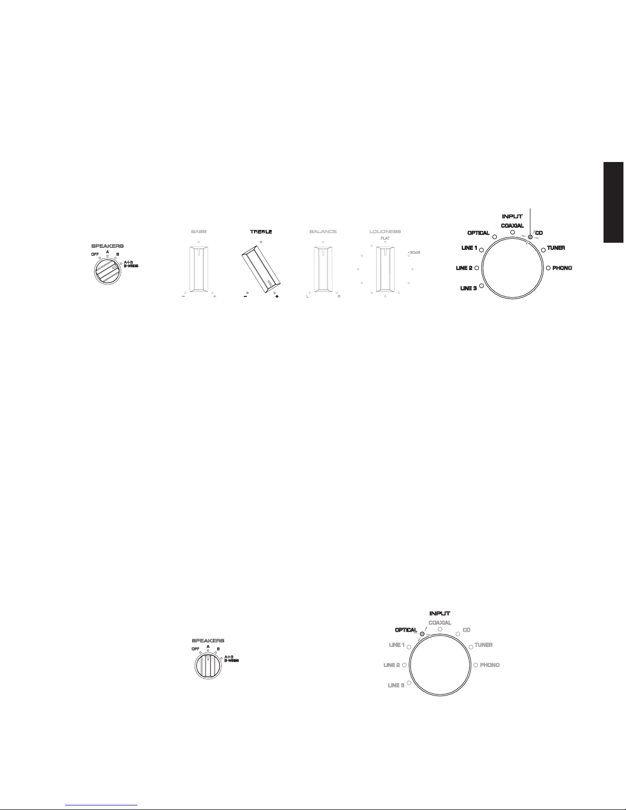
5. Indication of input source
The input source when the protection function was
activated is indicated.
Turn the “TREBLE” knob to “+” and the “SPEAKERS” knob to
“A+B”. (
Fig. 17)
The input source selected when the protection function
was activated is indicated using the “INPUT” indicators.
(Fig. 17)
• Factory Preset
The backup memory of the microprocessor will be
initialized, and the following stored settings will be
reverted to the factor
y presets. This operation is
called “factory preset”.
a. “INPUT” (CD)
b. Protection history (None)
c.
Number of times when protection is detected (0 times)
d. “PURE DIRECT” switch (OFF)
e.
“
z” (power) switch ON/OFF position
* In the parentheses ( ) are settings when shipped
from the factory.
Operation Procedures
With the self‑diagnostic function activated, follow the
steps below.
1. Set
the SPEAKERS knob to the “A” position to
reserve rever
ting to factory presets and the
“OPTICAL INPUT” indicator lights up. (Fig. 18)
2. Press the “z” (power) switch to turn off this unit,
and then press it again to turn it on and perform
the factory preset.
5. 入力ソースの表示
プロテクションが働いた時の入力ソースを表示します。
“
TREBLE” のツマミを“+ ” の位置にして、“SPEAKERS”
ツマミを
“
A+B” の位置にします。(Fig. 17)
プロテクションが働いた時に選択されていた入力ソース
が “INPUT” インジケーターに表示されます。(Fig. 17)
• ファクトリープリセット
マイコンのバックアップ用メモリーを初期化し、記
憶された下記の設定を工場出荷時に戻します。この
操作をファクトリープリセットと言います。
a. “INPUT”(CD)
b. プロテクション履歴(無し)
c. プロテクション検出回数(0 回)
d.
“
PURE DIRECT” スイッチ (OFF)
e.
“
z”( 電源)スイッチの ON/OFF
※ ( )内は工場出荷時
操作方法
ダイアグが起動した状態で下記の操作を行います。
1. SPEAKERS ツマミの位置を “A” にすると初期化が
予約され、“OPTICAL” インジケーターが点灯しま
す。(Fig. 18)
2.
“
z”(電源)スイッチを OFF にし、もう一度 ON
にして電源を入れると、ファクトリープリセット
が実行されます。
If CD was the input source when the protection
function was activated, the “CD” indicator lights up.
プロテクションが働いた時の入力ソースがCDの場合、
”CD”が点灯します。
Fig. 17
When factory preset is reserved
ファクトリープリセット予約時
Fig. 18

28
A-S501/A-S301
A-S501/A-S301
● Canceling Self-Diagnostic Function
To keep setup information stored in the backup
memory of the microprocessor:
Set the “SPEAKERS” knob to the “OFF”, “B” or “A+B” position
and press the “z” (power) key to turn off the power.
Self‑diagnostic function is canceled.
To initialize the backup memory of the
microprocessor and revert the following stored
settings to the factory presets:
Set the “SPEAKERS” knob to the “A” position, press the
“z” (power) key to turn off the power.
Self‑diagnostic function is canceled with the initialization
reserved.
When the “z” (power) switch is pressed again to turn on
this unit, the backup memory of the microprocessor will
be initialized, and the stored settings will be reverted to
the factory presets.
For details, refer to “Factory Preset” in the section “SELF‑
DIAGN
OSTIC FUNCTION”.
● ダイアグの解除
マイコンのバックアップ用メモリーに記憶されてい
る設定情報を保持する場合:
SPEAKERS ツマミを“OFF”、“B” または“A+B” に設定して、
“
z”(電源)スイッチを押して電源を切ります。
ダイアグが解除されます。
マイコンのバックアップ用メモリーを初期化し、記
憶された下記の設定を工場出荷時に戻す場合:
SPEAKERS ツマミを“A” に設定して、“z”(電源)スイッ
チを押して電源を切ります。
初期化が予約された状態でダイアグが解除されます。
もう一度 “z”(電源)スイッチを押して電源を入れると、
マイコンのバックアップ用メモリーを初期化し、記憶さ
れた設定を工場出荷時に戻します。
詳細は、ダイアグの
“
ファクトリープリセット ” を参照し
てください。
● プロテクション解除モードでの起動
注意!
プロテクションを解除した状態でのダイアグモードは、
危険な状態でもプロテクションが作動しないため、動作
させると、本機を破壊することがあります。
このモードを使用する場合は十分注意してください。
プロテクションが動作することにより、故障箇所の診断
に支障をきたすような場合は、次の方法によりプロテク
ションを解除した状態でダイアグモードに入ることがで
きます。
(過電流検出以外のプロテクション動作を解除する)
1. 本機の “z”(電源)スイッチを OFF にします。 (Fig.
19
)
2. 電源コードを AC コンセントに接続します。 (Fig.
19
)
3. “SPEAKERS” ツマミを
“
OFF” にします。 (Fig.19)
注意: “SPEAKERS” ツマミを “A” の位置で電源を切
るとファクトリープリセットが予約されるた
め、ダイアグの起動時に “SPEAKERS” ツマミ
を “OFF” の位置にします。
4. “BASS”、“T
REBLE”、“BALANCE” ツマミを中央の位
置に合わせます。 (Fig.
19
)
注意: “BASS”、“TREBLE”、“BALANCE” ツマミは必ず
中央の位置に合わせてください。ダイアグ起動
時この位置を記憶して各ツマミの中央位置の補
正をソフト的に行っています。
また、各ツマミの中央位置が入力電圧 2.5V の
±5%以上外れている場合にはダイアグが起動
できません。
5. “LOUDNESS” ツマミを “FLAT” の位置に合わせます。
(Fig.
19
)
● Starting in the Protection Cancel mode
CAUTION!
Using this product with the protection function disabled
may cause further damage to this unit. Use special care
for this point when using this mode.
If the protection function works and causes hindrance to
trouble shoot, cancel the protection function as described
below, and it will be possible to enter the self‑diagnostic
function mode.
(The protection functions other than the excess curre
nt
detect function will be disabled.)
1. Press the “z” (power) switch to turn off this unit. (Fig. 19)
2. Connect the power cable of this unit to the AC outlet.
(Fig.
19
)
3. Set the “SPEAKERS” knob to the “OFF” position. (Fig. 19)
Note:
Since factory preset is reserved by turning
off this unit when the “SPEAKERS” knob is set
to the “A” position, set the “SPEAKERS” knob
to the “OFF” position before startin
g the self‑
diagnostic function mode
.
4. Set the “BASS”, “TREBLE” and “BALANCE” knobs to
the top positions. (Fig.
19
)
Note:
Be sure to set the “BASS”, “TREBLE” and
“BALANCE” knobs to the top positions. These
positions are stored when the self‑diagnostic
function mode is started, and software corrections
are made to the top position for each selector.
In addition, the self diagnostic function mode
cannot be started if the top positions for the
knobs ar
e off by more than ± 5% of the 2.5 V
input voltage.
5. Set the “LOUDNESS” knob to the “FLAT” position. (Fig. 19)
 Loading...