

Yamaha AS-500, AS-300 Service Manual
INTEGRATED AMPLIFIER
A-S500/A-S300
SERVICE MANUAL
IMPORTANT NOTICE
This manual has been provided for the use of authorized YAMAHA Retailers and their service personnel.
It has been assumed that basic service procedures inherent to the industry, and more specifi cally YAMAHA Products, are already known
and understood by the users, and have therefore not been restated.
WARNING:
IMPORTANT:
The data provided is believed to be accurate and applicable to the unit(s) indicated on the cover. The research, engineering, and service
departments of YAMAHA are continually striving to improve YAMAHA products. Modifications are, therefore, inevitable and
specifi cations are subject to change without notice or obligation to retrofi t. Should any discrepancy appear to exist, please contact the
distributor's Service Division.
WARNING:
IMPORTANT:
Failure to follow appropriate service and safety procedures when servicing this product may result in personal injury,
destruction of expensive components, and failure of the product to perform as specifi ed. For these reasons, we advise
all YAMAHA product owners that any service required should be performed by an authorized YAMAHA Retailer or
the appointed service representative.
The presentation or sale of this manual to any individual or fi rm does not constitute authorization, certifi cation or
recognition of any applicable technical capabilities, or establish a principle-agent relationship of any form.
Static discharges can destroy expensive components. Discharge any static electricity your body may have
accumulated by grounding yourself to the ground buss in the unit (heavy gauge black wires connect to this buss).
Turn the unit OFF during disassembly and part replacement. Recheck all work before you apply power to the unit.
■ CONTENTS
TO SERVICE PERSONNEL ............................................2
IMPEDANCE SELECTOR ...............................................3
FRONT PANELS ............................................................. 3
REAR PANELS ...........................................................4–8
REMOTE CONTROL PANEL .......................................... 9
SPECIFICATIONS /
INTERNAL VIEW .......................................................... 11
SERVICE PRECAUTIONS /
DISASSEMBLY PROCEDURES /
UPDATING FIRMWARE /
ファームウェアの書き込み
101188
参考仕様
................................... 9–10
サービス時の注意事項
分解手順
.....................................16–20
........... 12–15
Copyright © 2010 All rights reserved.
This manual is copyrighted by YAMAHA and may not be copied or
redistributed either in print or electronically without permission.
..... 11
SELF-DIAGNOSTIC FUNCTION /
ダイアグ(自己診断機能)
AMP ADJUSTMENT /
IC DATA ...................................................................30–32
PIN CONNECTION DIAGRAMS .............................33–34
BLOCK DIAGRAM ........................................................ 35
PRINTED CIRCUIT BOARDS .................................36–52
SCHEMATIC DIAGRAMS ....................................... 53–61
REPLACEMENT PARTS LIST ................................ 63–79
REMOTE CONTROL .....................................................80
.......................................21–27
アンプ部調整
.......................28–29
P.O.Box 1, Hamamatsu, Japan
'10.09
A-S500/A-S300

A-S500/A-S300
■ TO SERVICE PERSONNEL
1. Critical Components Information
Components having special characteristics are marked ⚠ and
must be replaced with parts having specifications equal to those
originally installed.
2. Leakage Current Measurement (For 120V Models Only)
When service has been completed, it is imperative to verify
that all exposed conductive surfaces are properly insulated
from supply circuits.
• Meter impedance should be equivalent to 1500 ohms shunted
by 0.15 F.
For U model
“CAUTION”
“F1: FOR CONTINUED PROTECTION AGAINST RISK OF FIRE, REPLACE ONLY WITH SAME TYPE 8A(A-S500)
/ 6A(A-S300), 125V FUSE.”
For C model
CAUTION
F1: REPLACE WITH SAME TYPE 8A (A-S500) / 6A (A-S300), 125V FUSE.
ATTENTION
F1: UTILISER UN FUSIBLE DE RECHANGE DE MÉME TYPE DE 8A (A-S500) / 6A (A-S300), 125V.
WALL
OUTLET
• Leakage current must not exceed 0.5mA.
• Be sure to test for leakage with the AC plug in both polarities.
EQUIPMENT
UNDER TEST
INSULATING
TABLE
AC LEAKAGE
TESTER OR
EQUIVALENT
WARNING: CHEMICAL CONTENT NOTICE!
This product contains chemicals known to the State of California to cause cancer, or birth defects or other reproductive
harm.
DO NOT PLACE SOLDER, ELECTRICAL/ELECTRONIC OR PLASTIC COMPONENTS IN YOUR MOUTH FOR ANY REASON
WHATSOEVER!
Avoid prolonged, unprotected contact between solder and your skin! When soldering, do not inhale solder fumes or
expose eyes to solder/flux vapor!
If you come in contact with solder or components located inside the enclosure of this product, wash your hands before
handling food.
About lead free solder /
All of the P.C.B.s installed in this unit and solder joints are
soldered using the lead free solder.
Among some types of lead free solder currently available,
it is recommended to use one of the following types for
the repair work.
• Sn + Ag + Cu (tin + silver + copper)
• Sn + Cu (tin + copper)
• Sn + Zn + Bi (tin + zinc + bismuth)
A-S500/A-S300
Caution:
As the melting point temperature of the lead free solder
is about 30°C to 40°C (50°F to 70°F) higher than that of
the lead solder, be sure to use a soldering iron suitable
to each solder.
無鉛ハンダについて
本機に搭載されているすべての基板およびハンダ付けに
よる接合部は無鉛ハンダでハンダ付けされています。
無鉛ハンダにはいくつかの種類がありますが、修理時に
は下記のような無鉛ハンダの使用を推奨します。
Sn+Ag+Cu(錫+銀+銅)
Sn+Cu(錫 + 銅)
Sn+Zn+Bi(錫 + 亜鉛 + ビスマス)
注意:
無鉛ハンダの融点温度は通常の鉛入りハンダに比べ 30 〜
40℃程度高くなっていますので、それぞれのハンダに合っ
たハンダごてをご使用ください。
2
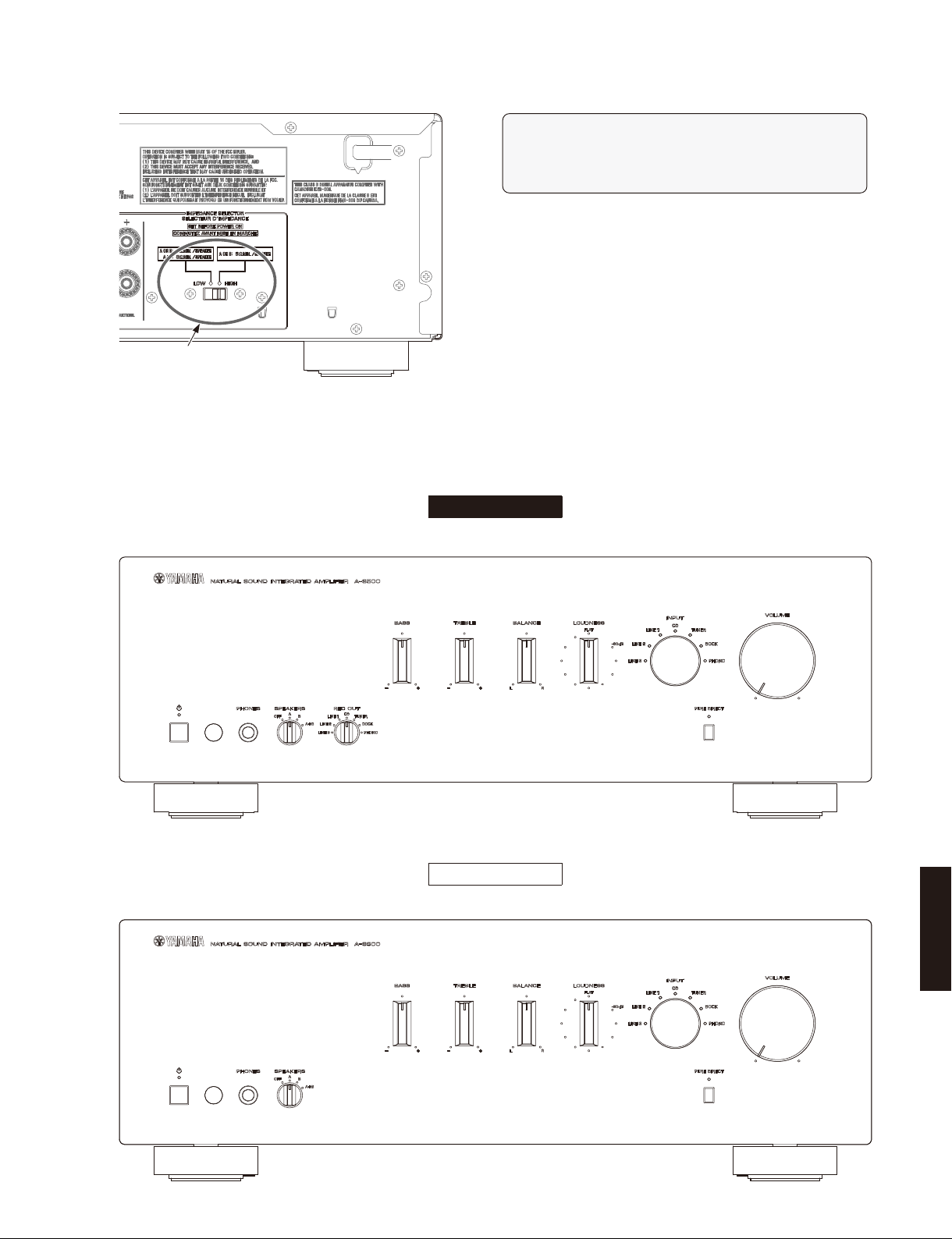
■ IMPEDANCE SELECTOR
IMPEDANCE SELECTOR
■ FRONT PANELS
A-S500/A-S300
WARNING:
Do not change the setting of the IMPEDANCE SELECTOR switch
when the unit power is switched on, as doing so may damage
the unit.
A-S500 (U, C, R, T, A, B, G, L models)
A-S300 (R, T, A, B, G, L, J models)
A-S500
A-S300
A-S500/A-S300
3
A-S500/A-S300
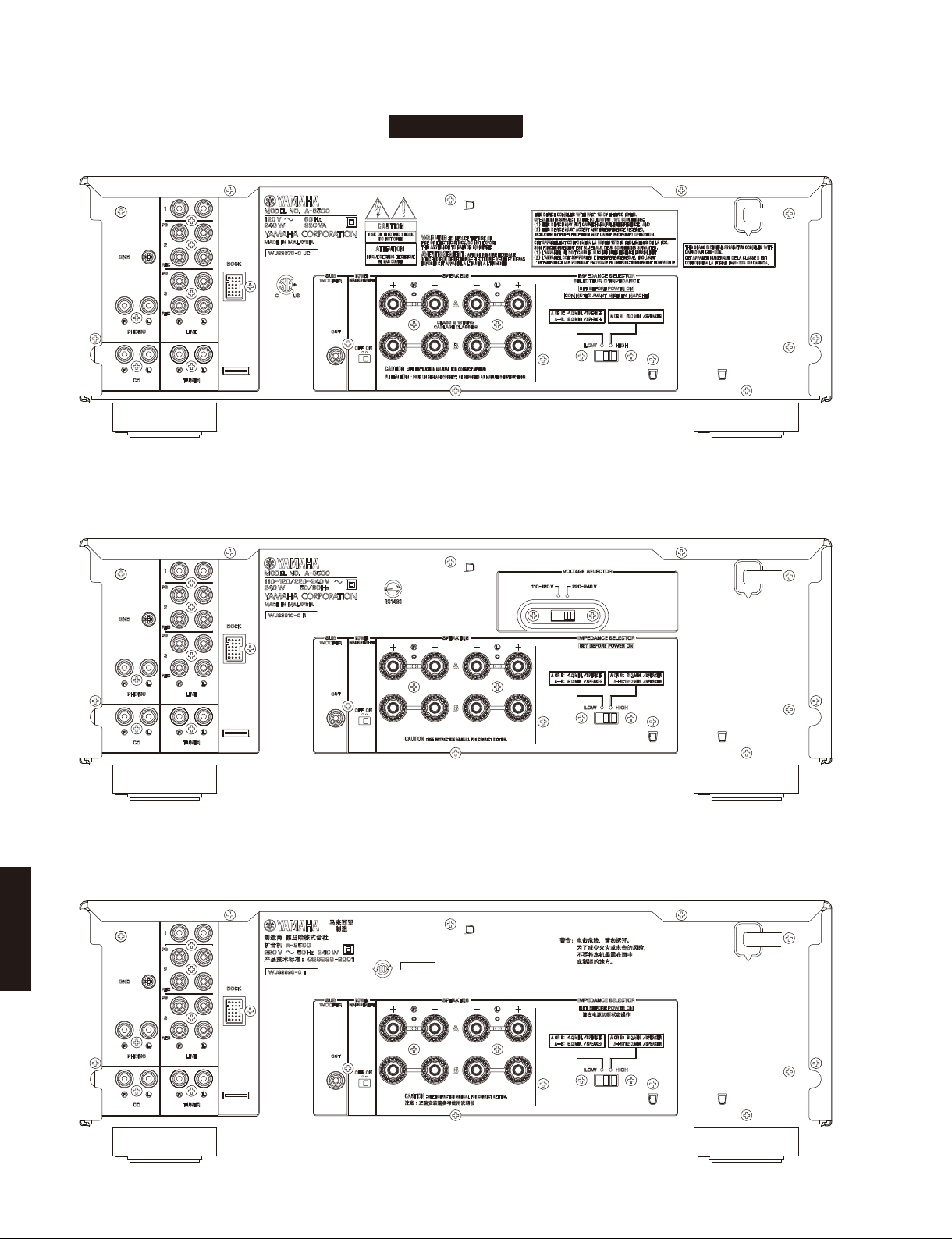
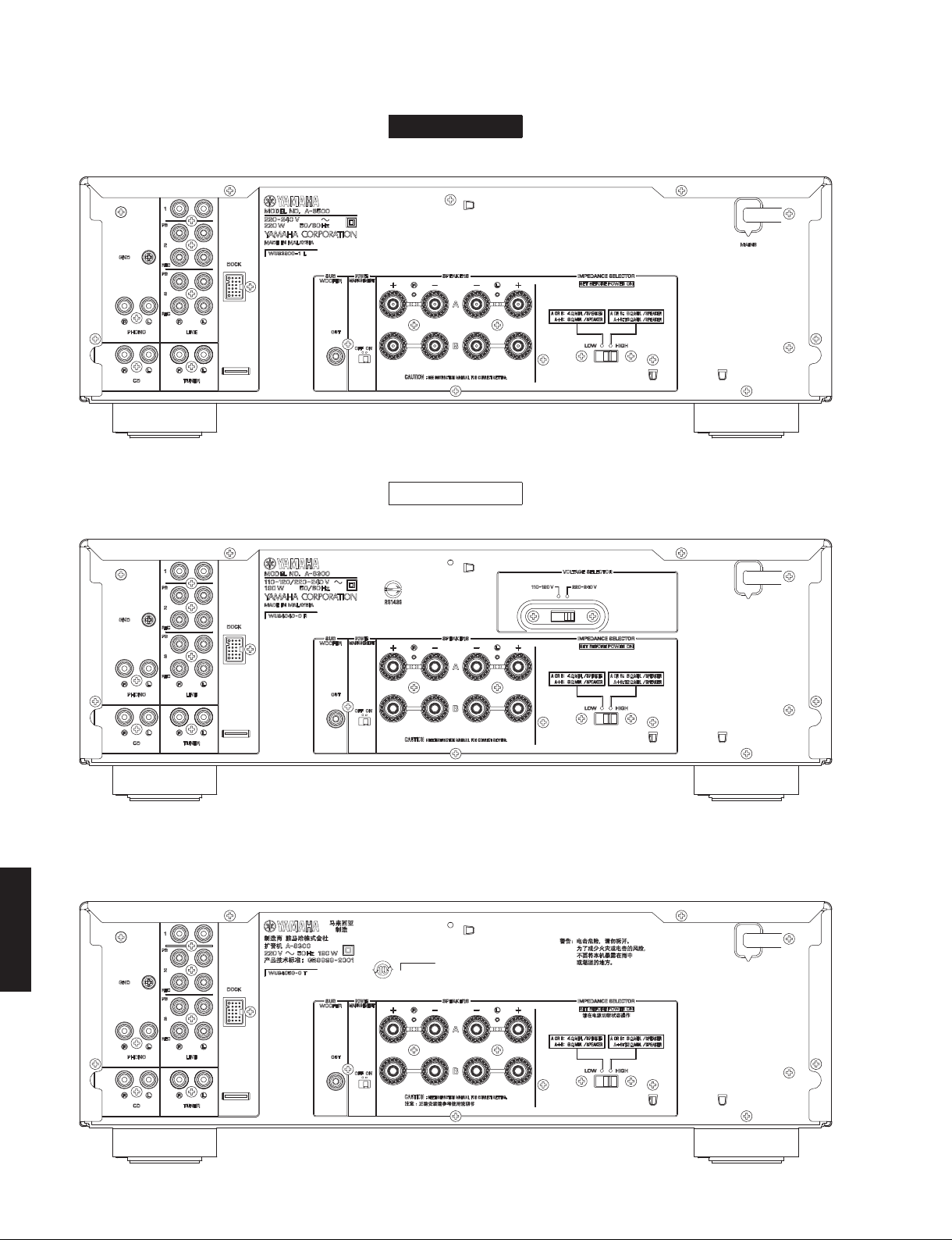
■ REAR PANELS
A-S500 (U, C models)
A-S500
A-S500 (R model)
A-S500 (T model)
A-S500/A-S300
4
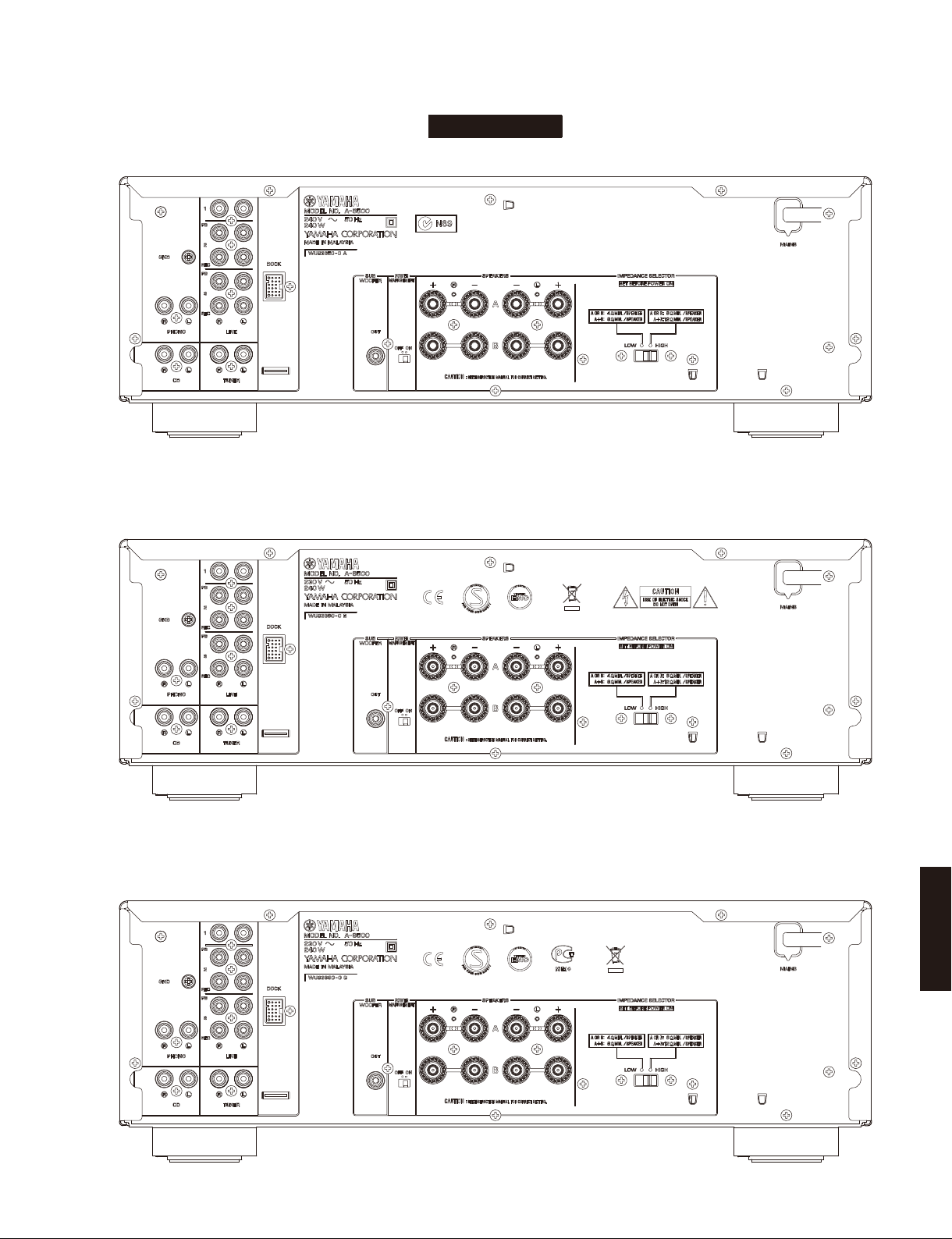
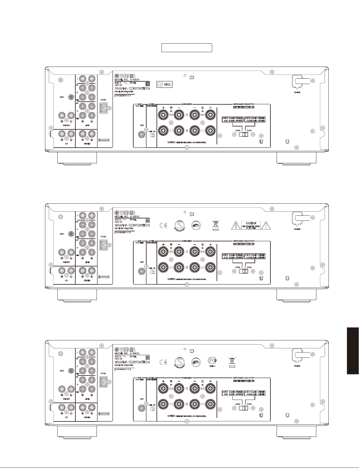
A-S500 (A model)
A-S500/A-S300
A-S500
A-S500 (B model)
A-S500 (G model)
A-S500/A-S300
5
A-S500/A-S300
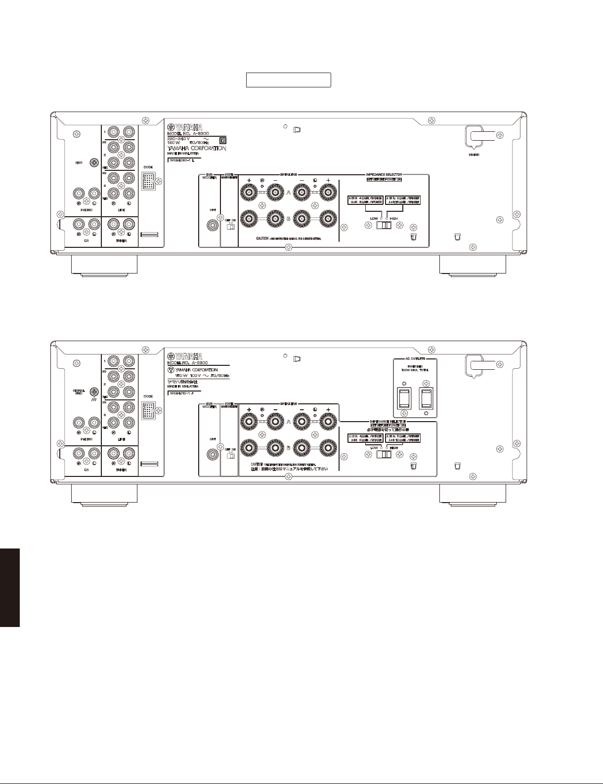
A-S500 (L model)
A-S500
A-S300 (R model)
A-S300 (T model)
A-S300
A-S500/A-S300
6
A-S300 (A model)
A-S500/A-S300
A-S300
A-S300 (B model)
A-S300 (G model)
A-S500/A-S300
7
A-S500/A-S300
A-S300 (L model)
A-S300
A-S300 (J model)
A-S500/A-S300
8
A-S500/A-S300
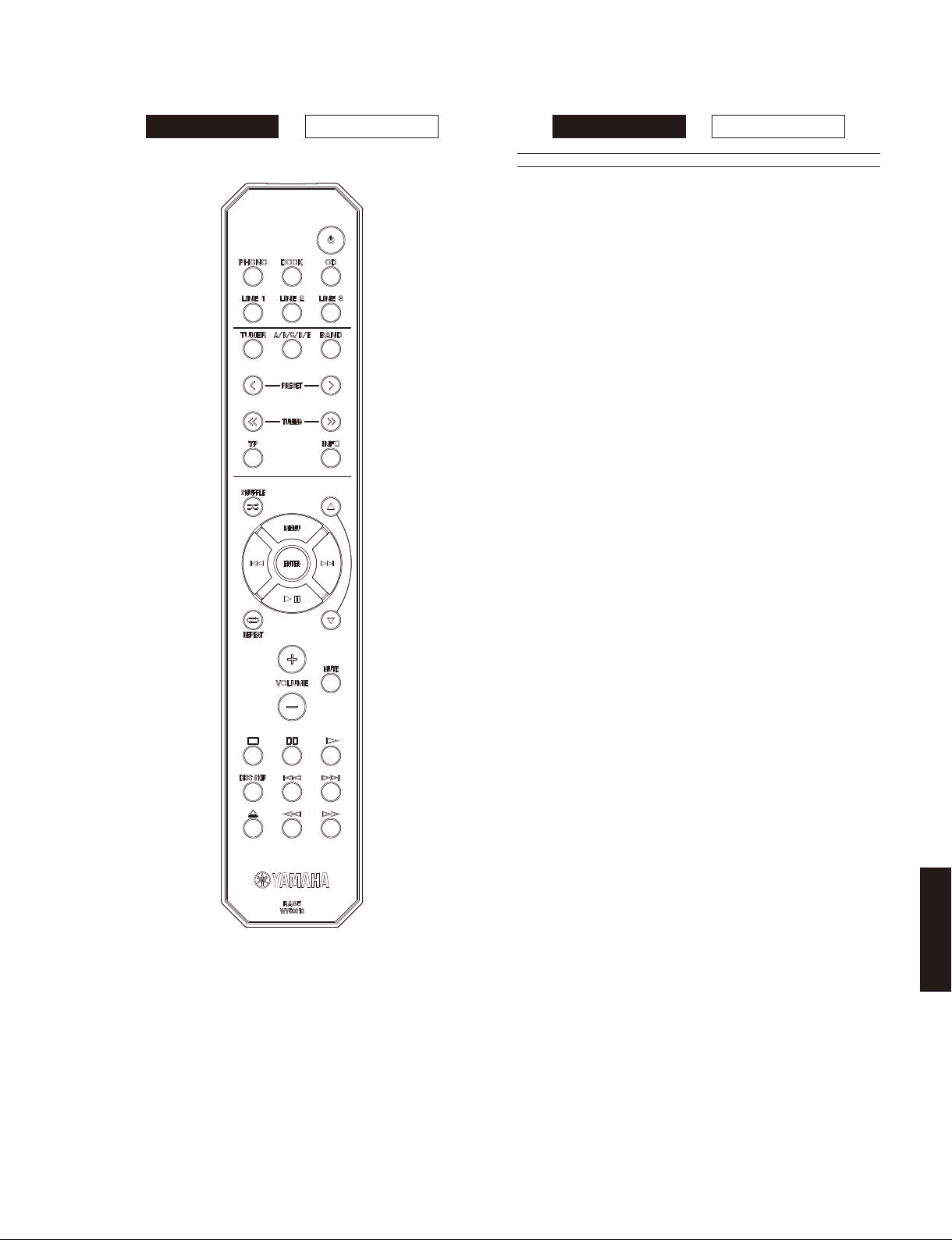
■ REMOTE CONTROL PANEL
A-S500 A-S300 A-S500 A-S300
RAS5
■ SPECIFICATIONS /
■ Audio Section /
Minimum RMS Output Power (Power Amp. Section) /
定格出力(パワーアンプ部)
(8 ohms, 20 Hz to 20 kHz, 0.019 % THD)
[A-S500] ..............................................................85 W + 85 W
[A-S300] ..............................................................60 W + 60 W
(6 ohms, 20 Hz to 20 kHz, 0.038 % THD)
[A-S500] (U, C, R, T, A, B, G models) .......... 100 W + 100 W
[A-S300] (U, C, R, T, A, B, G, J models) ..........70 W + 70 W
Dynamic Power Per Channel /
(8/6/4/2 ohms)
[A-S500] .....................................................130/150/185/220 W
[A-S300] .....................................................100/120/140/150 W
MAX Power Per Channel[B, G models]
(1 kHz, 0.7 % THD, 4 ohms)
[A-S500] ..........................................................................120 W
[A-S300] ............................................................................95 W
IEC Power [B, G models]
(1 kHz, 0.019 % THD, 8 ohms)
[A-S500] ..........................................................................100 W
[A-S300] ............................................................................75 W
Power Band Width /
[A-S500] (0.06 % THD, 42.5 W, 8 ohms) ........10 Hz to 50 kHz
[A-S300] (0.06 % THD, 30 W, 8 ohms) ...........10 Hz to 50 kHz
Damping Factor /
1 kHz, 8 ohms ......................................................... 240 or more
Maximum Effective Output Power /
(1 kHz, 10 % THD)
[A-S500]
R, T, L models (8 ohms) ................................................130 W
R, T models (6 ohms) ....................................................150 W
[A-S300]
R, T, L, J models (8 ohms) ............................................100 W
R, T, J models (6 ohms) ................................................110 W
Input Sensitivity/Input Impedance/
PHONO (MM) ..............................................3.0 mV / 47 k-ohms
CD, etc. ......................................................200 mV / 47 k-ohms
Maximum Input Signal /
PHONO (MM) (0.003 % THD) ...........................60 mV or more
CD, etc. (0.5 % THD) ...........................................2.2 V or more
Output Level/Output Impedance /
REC OUT .......................................200 mV / 1.0 k-ohms or less
Headphone Jack Rated Output/Impedance /
ヘッドフォン出力/出力インピーダンス
CD, etc.(Input, 1 kHz, 200 mV, 8 ohms)
[A-S500] ....................................................430 mV / 470 ohms
[A-S300] ....................................................360 mV / 470 ohms
Frequency Response /
CD, etc. (20 Hz to 20 kHz) ........................................0 ±0.5 dB
CD, etc. Pure DIRECT ON (10 Hz to 100 kHz) .........0 ±1.0 dB
RIAA Equalization Deviation /
PHONO (MM) ................................................................. ±0.5 dB
Total Harmonic Distortion /
PHONO (MM) to REC OUT (3 V) ..................... 0.025 % or less
[A-S500]
CD, etc. to SP OUT (42.5 W, 8 ohms)
.......................................................................0.015 % or less
[A-S300]
CD, etc. to SP OUT (30 W, 8 ohms)
..................................................................... 0.015 % or less
Signal to Noise Ratio /
PHONO (MM) (5 mV Input shorted) ................... 88 dB or more
CD, etc. (Pure DIRECT ON) (200 mV input shorted)
............................................................................ 100 dB or more
オーディオ部
パワーバンド
ダンピングファクター
最大許容入力
周波数特性
RIAA 偏差
全高調波歪率
信号対雑音比
参考仕様
ダイナミックパワー
(SPEAKER-A)
実用最大出力
入力感度/入力インピーダンス
(1kHz)
出力電圧/出力インピーダンス
(20 Hz to 20 kHz)
(IHF-A Network)
(IHF)
(JEITA)
A-S500/A-S300
9
A-S500/A-S300
Residual Noise /
.............................................................................................30 µV
Channel Separation /
CD, etc. (Input 5.1 k-ohms shorted)
1kHz ................................................................. 65 dB or more
10kHz ............................................................... 50 dB or more
Tone Control Characteristics /
BASS
Boost/Cut (50 Hz) ............................................................... ±10 dB
Turnover frequency .............................................................350 Hz
TREBLE
Boost/Cut (20 kHz) ............................................................. ±10 dB
Turnover frequency ............................................................ 3.5 kHz
Continuous Loudness Control /
コンティニュアスラウドネスコントロール
Attenuation /
Gain Tracking Error /
(0 to -99 dB) ........................................................0.5 dB or less
残留ノイズ
最大補正率
(IHF-A Network)
チャンネルセパレーション
トーンコントロール特性
(1 kHz) ............................................-30 dB
GAIN トラッキングエラー
U ........................U.S .A. model
C ..................Canadian model
R .....................General model
T..................... Chinese model
A .................Australian model
iPhone, iPod, iPod classic, iPod nano and iPod touch are trademarks of
Apple Inc., registered in the U.S. and other countries.
iPhone、iPod、iPodclassic、iPodnano、iPodtouch は、米国およびその他の国々
で登録されている AppleInc. の商標です。
B .......................British model
G ..................European model
L..................Singapore model
J .................. Japanese model
A-S500 A-S300
■ General /
Power Supply /
U, C models ............................................................ AC 120 V, 60 Hz
R model ........................................AC 110-120/220-240 V, 50/60 Hz
T model ................................................................... AC 220 V, 50 Hz
A model .................................................................. AC 240 V, 50 Hz
B, G models ............................................................ AC 230 V, 50 Hz
L model ....................................................... AC 220-240 V, 50/60 Hz
J model .............................................................. AC 100 V, 50/60 Hz
Power Consumption /
[A-S500]
U, C models ............................................................ 240 W, 330 VA
R, T, A, B, G models ............................................................. 240 W
L model ................................................................................ 220 W
[A-S300]
R, T, A, B, G, L models ......................................................... 190 W
J model ................................................................................150 W
Standby Power Consumption /
................................................................................ 0.5 W or less
YID-W10 Standby Power Consumption (YID-W10 connect) /
YID-W10
................................................................................ 1.2 W or less
iPod Charge Power Consumption /
[A-S500] .................................................................. 35 W or less
[A-S300] .................................................................. 25 W or less
Maximum Power Consumption [R model]
(1 kHz, 6 ohms, 10 % THD)
[A-S500] ..........................................................................510 W
[A-S300] ..........................................................................400 W
AC Outlets /
[A-S300]
Switched x 2 .........................................................100 W max. total
Dimensions (W x H x D) /
..............................435 x 151 x 387 mm (17-1/8" x 6" x 15-1/4")
A-S500/A-S300
Weight / 質量
[A-S500] .........................................................10.3 kg (22.7 lbs.)
[A-S300] ...........................................................9.0 kg (19.8 lbs.)
Finish /
Black color ................................. U, C, R, A, B, G, L, J models
Silver color ....................................... R, T, A, B, G, L, J models
Accessories /
Remote control .......................................................................x 1
Battery (R6, AA, UM-3) .......................................................... x 2
総合
電源電圧
消費電力
待機時消費電力
待機時消費電力(YID-W10 接続時)
iPod 充電時消費電力
AC アウトレット
仕上げ
付属品
[J model]
寸法(幅 × 高さ × 奥行き)
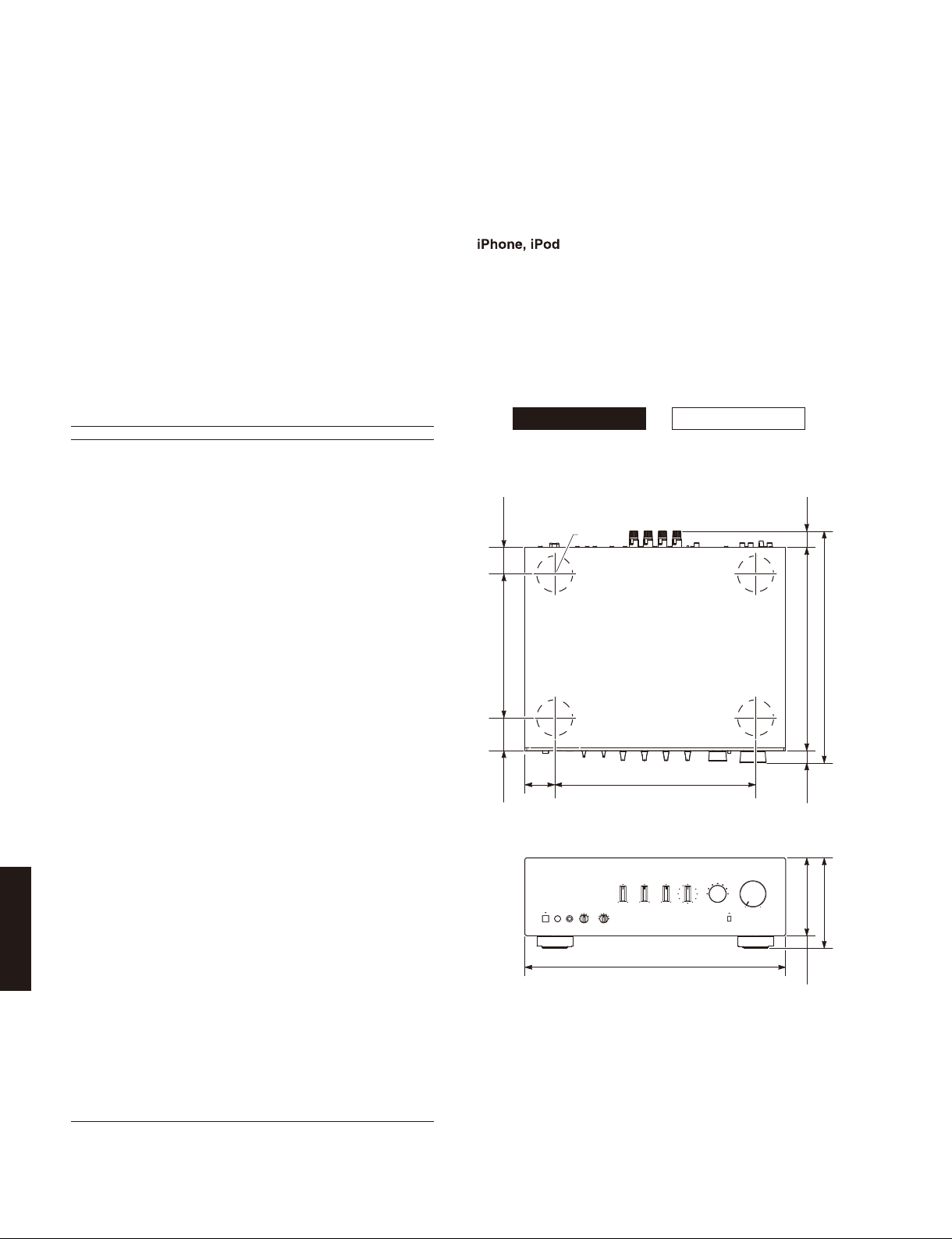
• DIMENSIONS /
Top view
46
(1-3/4")
240 (9-1/2")
55
(2")
(2-1/8")
ø 60
寸法図
335 (13-1/4")50
25.5
(1")
387 (15-1/4")
341 (13-3/8")
20.5
(3/4")
Front view
130 (5-1/8")
435 (17-1/8")
151 (5-7/8")
21
(7/8")
Unit: mm (inch)
単位:mm(インチ)
* Specifications are subject to change without notice.
※ 参考仕様および外観は、製品の改良のため予告なく変更すること
があります。
10
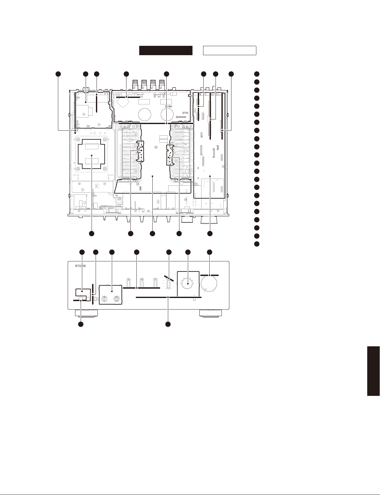
■ INTERNAL VIEW
Top view
12
Front view
34 5 876
13 1012
14 16 17 18 201915
A-S500 A-S300
911
A-S500/A-S300
1
OPERATION (1) P.C.B.
2
MAIN (6) P.C.B.
3
MAIN (5) P.C.B. (J model)
4
OPERATION (7) P.C.B. (R model)
5
MAIN (2) P.C.B.
6
DOCK P.C.B.
7
FUNCTION (2) P.C.B.
8
FUNCTION (3) P.C.B.
9
FUNCTION (1) P.C.B.
10
MAIN (4) P.C.B.
11
MAIN (1) P.C.B.
12
MAIN (3) P.C.B.
13
POWER TRANSFORMER
14
OPERATION (11) P.C.B.
15
OPERATION (8) P.C.B.
16
OPERATION (6) P.C.B.
17
OPERATION (3) P.C.B.
18
OPERATION (4) P.C.B.
19
OPERATION (5) P.C.B.
20
OPERATION (9) P.C.B.
21
OPERATION (2) P.C.B.
22
OPERATION (10) P.C.B.
2122
■ SERVICE PRECAUTIONS /
サービス時の注意事項
Safety measures
• Some internal parts in this product contain high voltages
and are dangerous. Be sure to take safety measures
during servicing, such as wearing insulating gloves.
• Note that the capacitors indicated below are dangerous
even after the power is turned off because an electric
charge remains and a high voltage continues to exist
there.
Before starting any repair work, connect a discharging
resistor (5k-ohms/10W) to the terminals of each
capacitor indicated below to discharge electricity. The
time required for discharging is about 30 seconds per
each.
C134, C135 on MAIN (1) P.C.B.
For details, refer to “PRINTED CIRCUIT BOARDS: MAIN
(1) P.C.B.”.
A-S500/A-S300
安全対策
・ この製品の内部には高電圧部分があり危険です。修理
の際は、絶縁性の手袋を使用するなどの安全対策を
行ってください。
・ 下記のコンデンサには電源を OFF にした後も電荷が残
り、高電圧が維持されており危険です。
修理作業前に放電用抵抗(5k Ω /10W)を下記の各コ
ンデンサの端子間に接続して放電してください。放電
所用時間は各々約 30 秒間です。
MAIN(1)P.C.B. の C134、C135
詳しくは “PRINTEDCIRCUITBOARDS:MAIN(1)P.C.B.”
を参照してください。
11
A-S500/A-S300
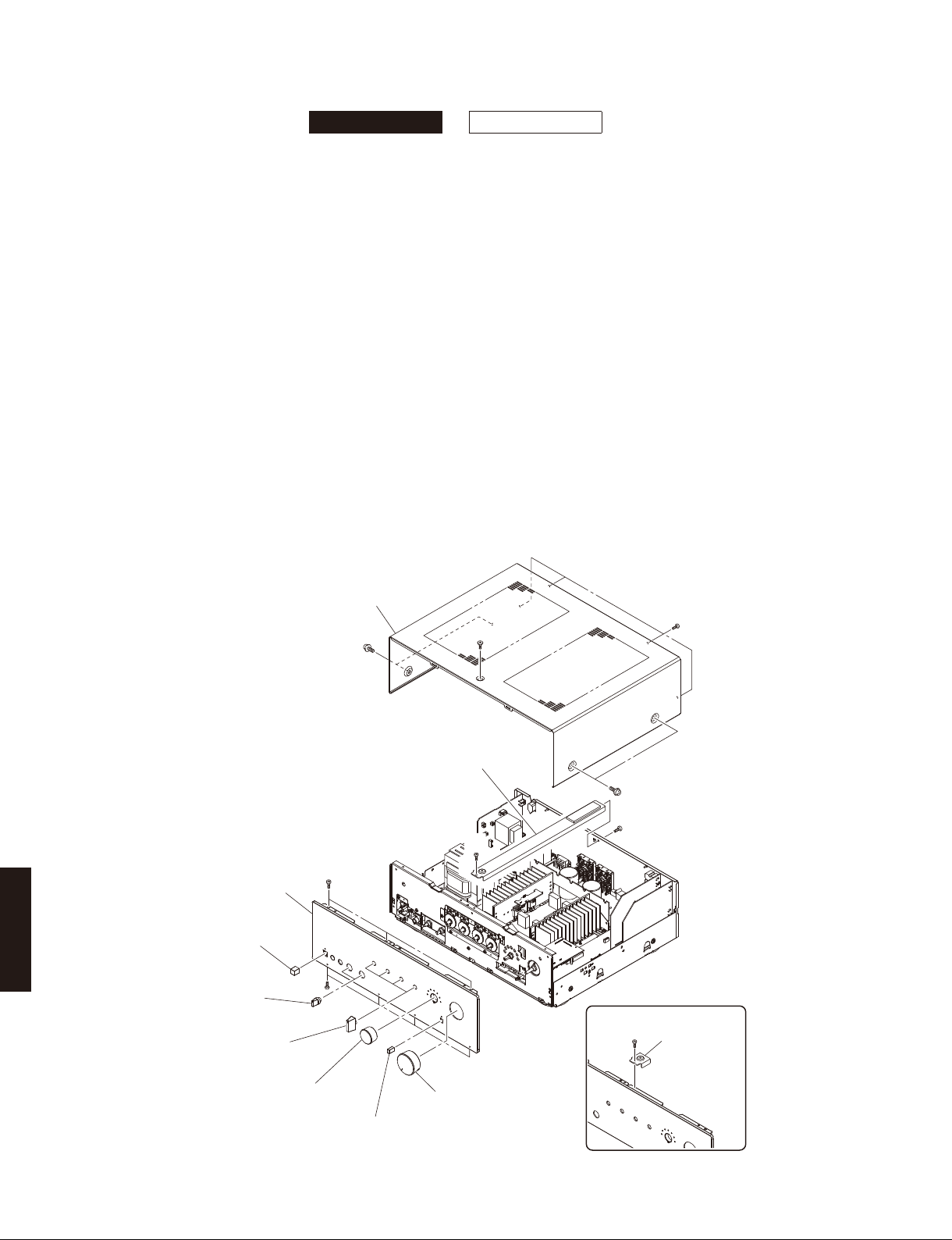
■ DISASSEMBLY PROCEDURES /
A-S500 A-S300
(Remove parts in the order as numbered.)
Disconnect the power cable from the AC outlet.
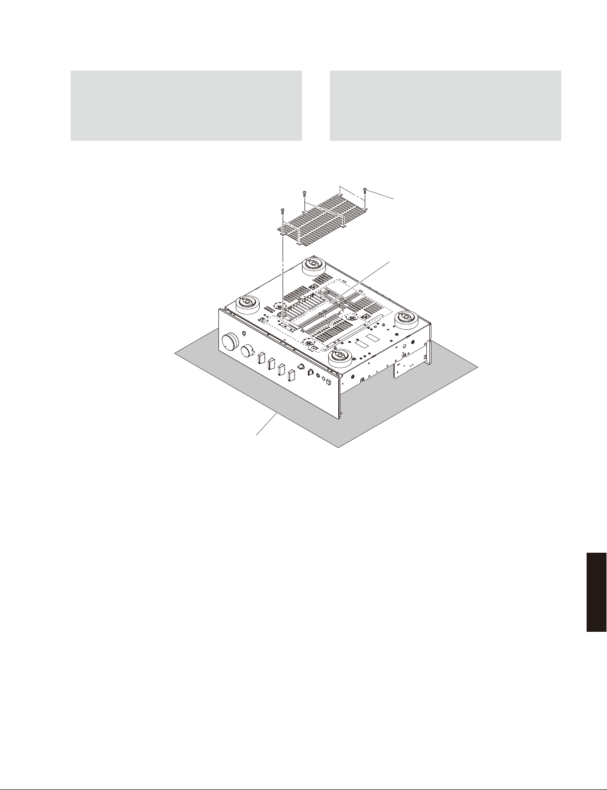
1. Removal of Top Cover
a. Remove 4 screws (①), 4 screws (②) and screw (③).
(Fig. 1)
b. Remove the top cover. (Fig. 1)
2. Removal of Front Panel Unit
a. (A-S500)
Remove screw (④), screw (⑤) and then remove the
frame top. (Fig. 1)
(A-S300)
Remove screw (⑥) and then remove the support top.
(Fig. 1)
b. Pull out the knobs and caps. (Fig. 1)
c. Remove 7 screws (⑦). (Fig. 1)
d. Remove the front panel unit. (Fig. 1)
分解手順
(番号順に部品を取り外してください。)
AC 電源コンセントから、電源コードを抜いてください。
1.トップカバーの外し方
a. ①ネジ 4 本、②のネジ 4 本、③のネジ 1 本を外します。
(Fig.1)
b. トップカバーを取り外します。(Fig.1)
2. フロントパネルユニットの外し方
a.(A-S500)
④のネジ 1 本、⑤のネジ 1 本を外し、フレーム TOP
を取り外します。(Fig.1)
(A-S300)
⑥のネジ 1 本を外し、サポート TOP を取り外します。
(Fig.1)
b. ノブ、キャップを取り外します。(Fig.1)
c. ⑦のネジ 7 本を外します。(Fig.1)
d. フロントパネルユニットを前方へ取り外します。
(Fig.1)
Top cover
トップ カ バ ー
①
Front panel unit
フロントパネルユニット
Cap POWER
キャップPOWER
A-S500/A-S300
Knob SP13
ノブSP13
Knob TC
ノブTC
⑦
⑦
③
(A-S500)
Frame top
フレームTOP
①
⑤
④
⑥
②
(A-S300)
Support top
サポートTOP
12
Knob INPUT
ノブINPUT
Cap DIRECT
キャップDIRECT
Knob VOL
ノブVOL
Fig. 1
A-S500/A-S300
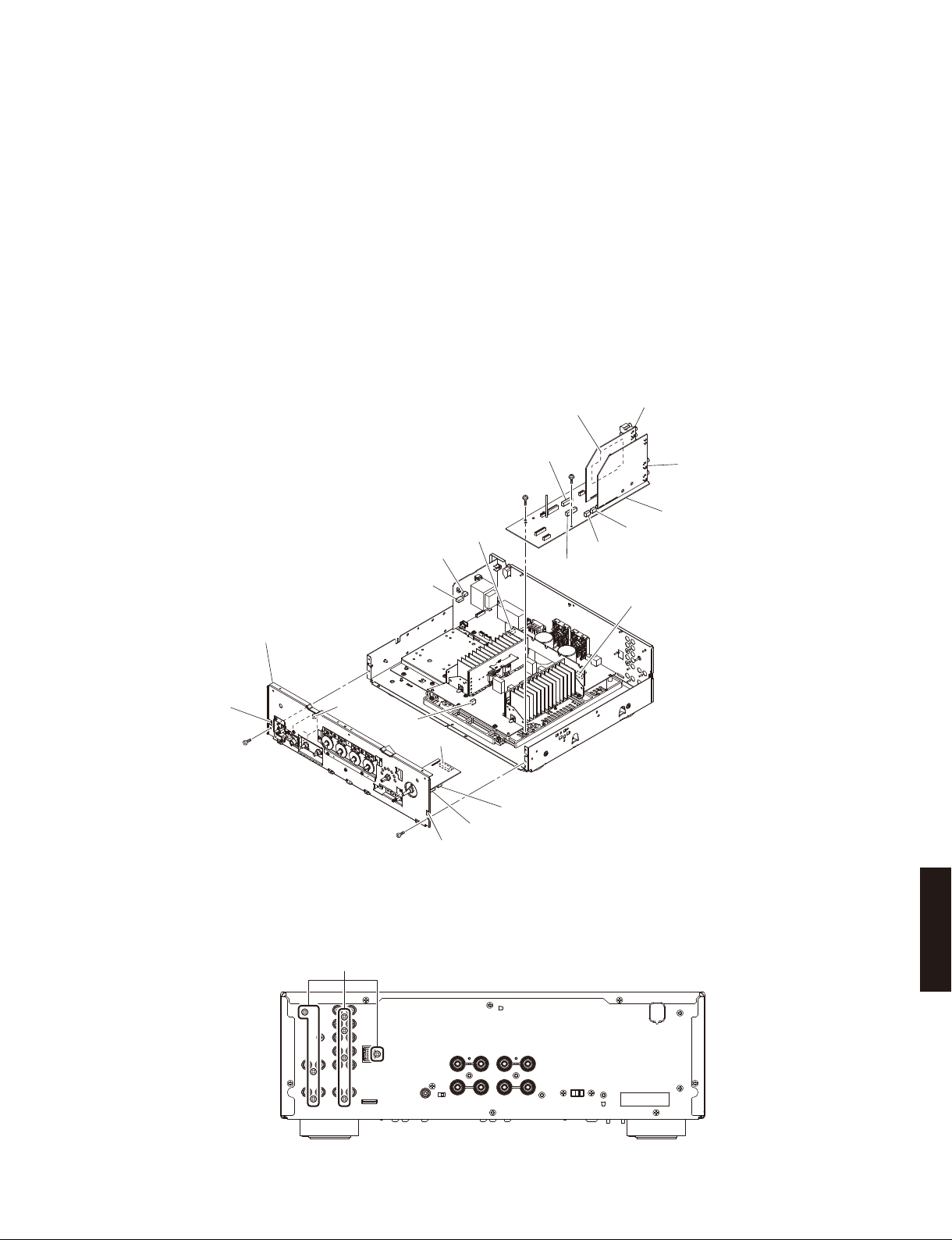
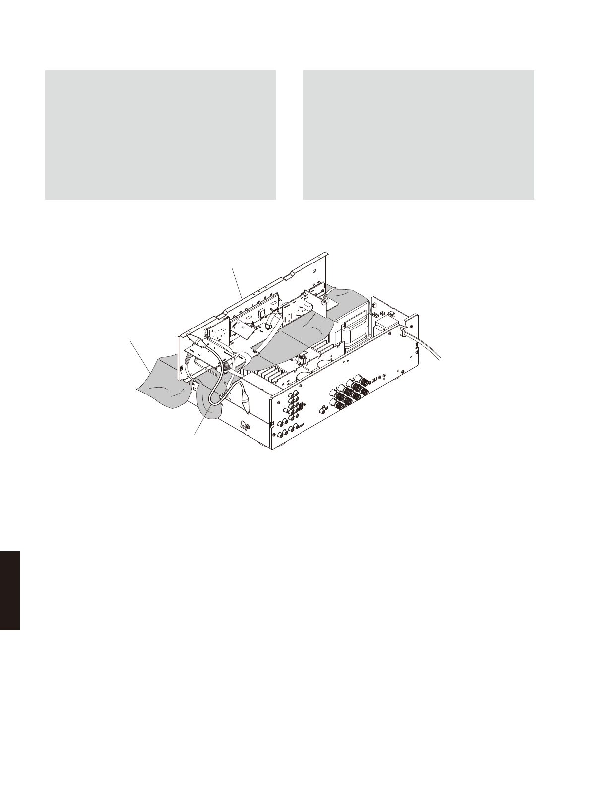
3. Removal of Sub-chassis Unit
a. Remove 2 screws (⑧). (Fig. 2)
b. Remove CB101, CB108, CB503-505, CB706, CB851
and CB853-854. (Fig. 2)
c. Release 2 hooks and then remove the sub-chassis
unit. (Fig. 2)
4. Removal of FUNCTION (1)–(3) and DOCK P.C.B.s
a. Remove 8 screws (⑨). (Fig. 3)
b. Remove screw (⑩) and screw (⑪). (Fig. 2)
c. Remove CB2, CB14, CB21 and CB506. (Fig. 2)
d. Remove the FUNCTION (1)–(3) P.C.B.s and DOCK
P.C.B. together. (Fig. 2)
CB14
CB21
CB2
Sub-chassis unit
サブシャーシユニット
3.サブシャーシユニットの外し方
a. ⑧のネジ 2 本を外します。(Fig.2)
b. CB101、CB108、CB503 〜 505、CB706、CB851、
CB853 〜 854 を外します。(Fig.2)
c. フック 2 箇所を外し、サブシャーシユニットを取り外
します。(Fig.2)
4. FUNCTION(1) 〜 (3)、DOCKP.C.B. の外し方
a. ⑨のネジ 8 本を外します。(Fig.3)
b. ⑩のネジ 1 本、⑪のネジ 1 本を外します。(Fig.2)
c. CB2、CB14、CB21、CB506 を外します。(Fig.2)
d. FUNCTION(1)〜(3)P.C.B. と DOCKP.C.B. を一緒に
取り外します。(Fig.2)
DOCK P.C.B.
CB506
⑪
⑩
CB503
FUNCTION (2) P.C.B.
FUNCTION (3) P.C.B.
FUNCTION (1) P.C.B.
CB505
CB504
CB108
Hook
フック
CB706
CB101
⑧
CB851
CB854
⑧
Hook
フック
CB853
A-S500/A-S300
Fig. 2
⑨
Fig. 3
13
A-S500/A-S300
When checking the P.C.B.s:
• Put the rubber sheet and cloth over this unit. Then
place the sub-chassis unit on the cloth and check it.
(Fig. 4)
• Connect the ground point of the sub-chassis unit to
the chassis with a ground lead or the like. (Fig. 4)
• Reconnect all cables (connectors) that have been
disconnected.
• When connecting the flexible flat cable, be careful
with polarity.
Sub-chassis unit
サブシャーシユニット
Rubber sheet and cloth
ゴムシートと布
P.C.B. をチェックする場合には:
・ 本機の上にゴムシートと布を敷き、その上にサブ
シャーシユニットを置いてチェックします。(Fig.4)
・ サブシャーシユニットのアースをリード線等で
シャーシに接続してください。(Fig.4)
・ 外したケーブル(コネクター)をすべて接続します。
・ フラットケーブルを接続する際、極性に注意してく
ださい。
Ground lead
アース線
Fig. 4
A-S500/A-S300
14
A-S500/A-S300
When checking the MAIN (1) P.C.B.:
• Spread the rubber sheet and the cloth. Then place
this unit on the cloth upside down. (Fig. 5)
• Remove 6 screws (⑫) and then remove the chassis
cover. (Fig. 5)
⑫
MAIN(1)P.C.B. をチェックする場合には:
・ ゴムシートと布を敷き、本機を上下反転して置きます。
(Fig.5)
・ ⑫のネジ6 本を外しシャーシカバーを取り外します。
(Fig.5)
⑫
⑫
Chassis cover
シャーシカバー
MAIN (1) P.C.B.
Rubber sheet and cloth
ゴ ム シ ートと布
Fig. 5
A-S500/A-S300
15

A-S500/A-S300
■ UPDATING FIRMWARE /
ファームウェアの書き込み
A-S500 A-S300
When the following parts are replaced, the firmware must
be updated to the latest version.
FUNCTION P.C.B.
Microprocessor (IC502: FUNCTION P.C.B.)
● Confirmation of firmware version
Before and after updating the firmware, check the
firmware version by using the self-diagnostic function
menu.
Start up the self-diagnostic function, have the
firmware version displayed, and note them down.
(See “SELF-DIAGNOSTIC FUNCTION”)
* When the firmware version is different from written
one, perform the UPDATING FIRMWARE from the
beginning.
● Initializing the back-up IC (EEPROM: IC503 of the FUNCTION P.C.B.)
After updating the firmware, the back-up IC MUST be
initialized by the following procedure to have proper
memorization of the set up information.
Start up the self-diagnostic function.
(See “SELF-DIAGNOSTIC FUNCTION”)
Set the SPEAKERS selector to the “A” position, press
the “
” (power) key to turn off the power once and
press the “
Then the back-up IC is initialized.
” (power) key to turn on the power again.
下記の部品を交換した場合、ファームウェアを最新バー
ジョンにアップデートする必要があります。
FUNCTIONP.C.B.
Microprocessor(IC502:FUNCTIONP.C.B.)
● ファームウェアのバージョンの確認
ファームウェアのアップデートの前後に、ファーム
ウェアのバージョンをダイアグで確認します。
ダイアグを起動してファームウェアのバージョンを
表示し、それらを書きとめます。
(「ダイアグ」参照)
※ ファームウェアバージョンが、書き込まれたもの
と異なる場合、ファームウェアのアップデートを
最初からやり直してください。
● バックアップ IC の初期化
(EEPROM:FUNCTIONP.C.B. の IC503)
ファームウェアのアップデート後、設定情報を正常
に記憶するために、下記の方法でバックアップ IC を
初期化する必要があります。
本機のダイアグを起動します。
(「ダイアグ」参照)
SPEAKERS セレクターを “A” の位置にし、“
キーを押して電源をいったん切り、再び “
キーを押して電源を入れるとバックアップ IC が初期
化されます。
”(パワー)
”(パワー)
● Required Tools
• Firmware downloader program
FlashSta.exe
• Firmware
ASx00_xxx.mot
ASx00_xxx.id
• RS-232C cross cable “D-sub 9 pin female”
(Specifications)
A-S500/A-S300
16
Pin No.2 RxD Pin No.2 RxD
Pin No.3 TxD Pin No.3 TxD
Pin No.5 GND Pin No.5 GND
Pin No.7 RTS Pin No.7 RTS
Pin No.8 CTS Pin No.8 CTS
• RS-232C conversion adaptor (Part No.: WR492800)
● 必要なツール
・ ファームウェア書き込み用プログラム
FlashSta.exe
・ ファームウェア
ASx00xxx.mot
ASx00xxx.id
・ RS-232C クロスケーブル “D-sub9pin メス”
(仕様)
Pin No.2 RxD Pin No.2 RxD
Pin No.3 TxD Pin No.3 TxD
Pin No.5 GND Pin No.5 GND
Pin No.7 RTS Pin No.7 RTS
Pin No.8 CTS Pin No.8 CTS
・ RS-232C 変換アダプター ( 部品番号:WR492800)
A-S500/A-S300
● Preparation and precautions
• Download the firmware downloader program and
the latest firmware from the specified download
source to the same folder of the PC.
• Prepare the above specified RS-232C cross
cable.
• While writing the firmware, keep the other application
software on the PC closed.
It is also recommended to keep the software on the
task tray closed as well.
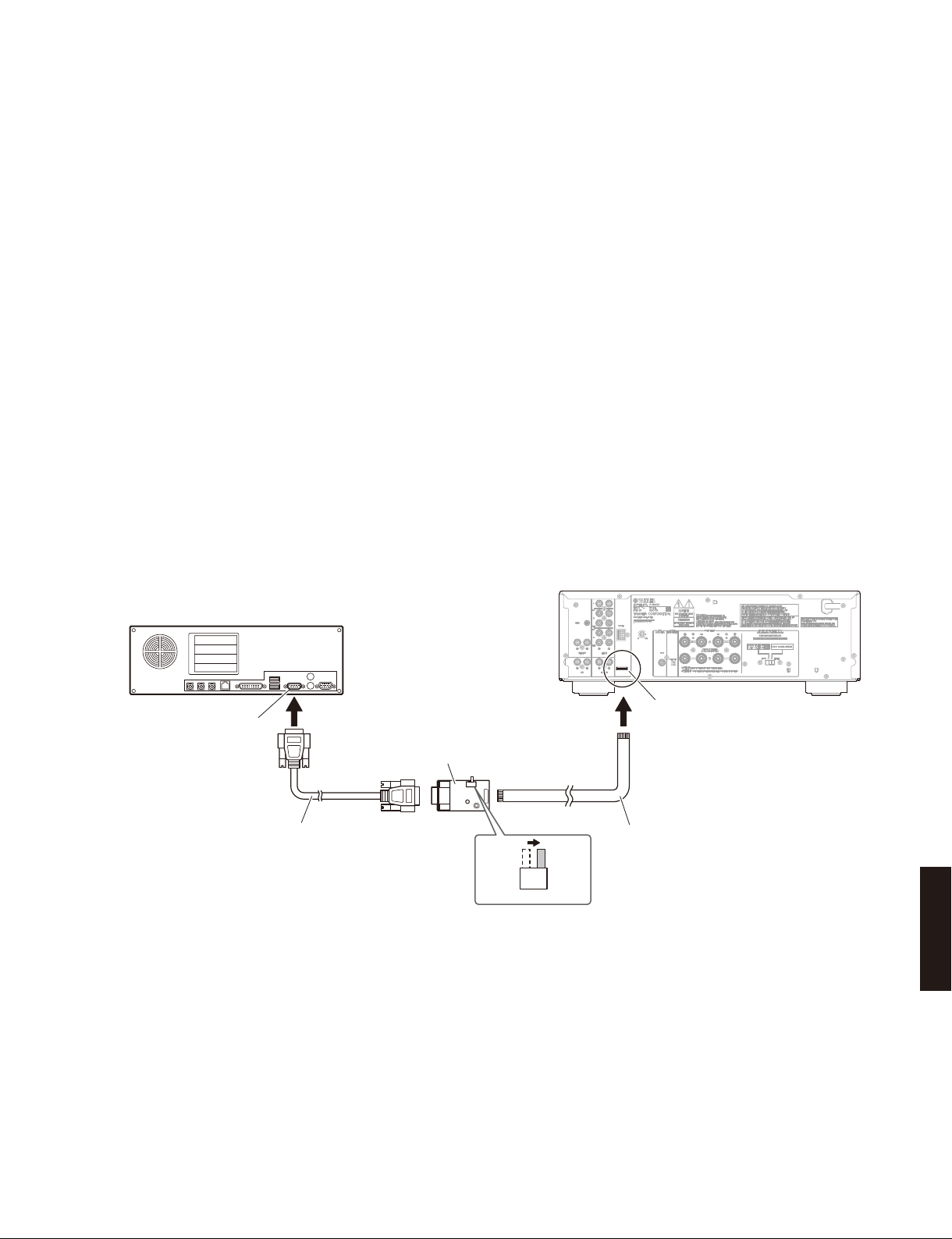
● Connection
* Disconnect the power cable of this unit from the
AC outlet
• Set the switch (SW7) of RS-232C conversion
adaptor to the “FLASH UCOM” position. (Fig. 1)
• Connect the writing port (CB509 of the FUNCTION
P.C.B.) located on the rear panel of this unit to
the serial port (RS-232C) of the PC with RS-232C
cross cable, RS-232C conversion adaptor and
flexible flat cable as shown below. (Fig. 1)
● 準備と注意
・ 指定のダウンロード先から、ファームウェア書き
込み用プログラムと最新のファームウェアを、PC
の同じフォルダにダウンロードしてください。
・ RS-232C クロスケーブルは必ず上記仕様のものを
用意してください。
・ 書き込み時は、PC 上の他のアプリケーションソ
フトは閉じてください。
さらに、タスクトレイ上にあるソフトも閉じてお
くことを推奨します。
● 接続
※ 本機の電源コードを AC コンセントから抜いてく
ださい。
・ RS-232C 変換アダプターのスイッチ(SW7)“FLASH
UCOM” 側に設定します。(Fig.1)
・ 本機の書き込み用ポート(FUNCTIONP.C.B. の
CB509)と PC のシリアルポート(RS-232C)を下
記のように接続します。(Fig.1)
PC
Serial port (RS-232C)
シリアルポート(RS-232C)
RS-232C cross cable
RS-232Cクロスケーブル
RS-232C conversion adaptor
RS-232C変換アダプター
SW7
FLASH
UCOM
OTHER
Fig. 1
This unit /本機
Writing port
(FUNCTION P.C.B. CB509)
Flexible flat cable (9P)
カード電線(9P)
A-S500/A-S300
17
A-S500/A-S300
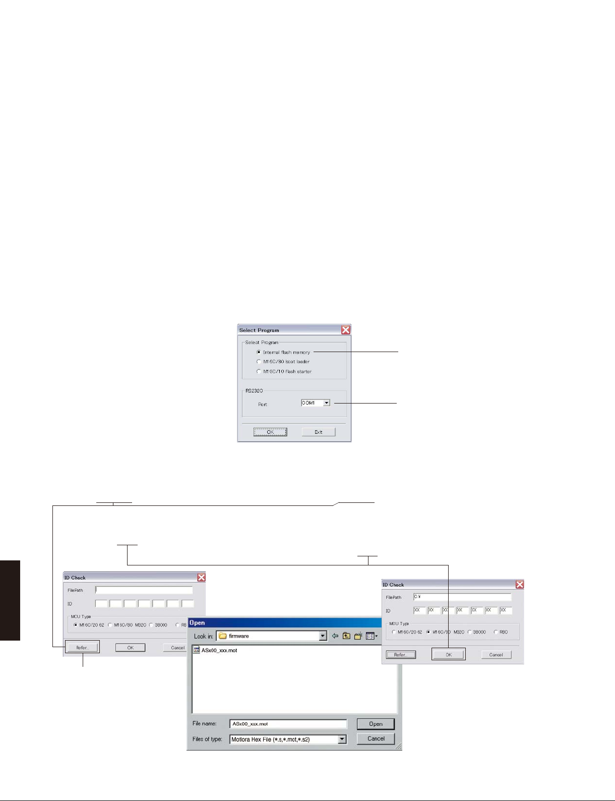
● Operation procedure
1. Connect the power cable of this unit to the AC
outlet.
The power to this unit is supplied and the
microprocessor is in the writing mode.
2. Start up FlashSta.exe.
The screen appears as shown below. (Fig. 2)
3. Select the data to be transmitted and port. (Fig. 2)
• Select Program
Select Internal flash memory.
• RS-232C
Select the port of RS-232C
* For selection of the port, COM1 to 4 can be
used.
As COM5 or higher port cannot be used,
select out of COM 1 to 4 of the setting on the
PC side.
● 操作方法
1. 本機の電源コードを AC コンセントに接続します。
本機に電源が入り、マイコンが書き込みモードに
なります。
2. FlashSta.exe を起動します。
下記の画面が表示されます。(Fig.2)
3. 送信データ、ポートを選択します。(Fig.2)
・ SelectProgram
Internalflashmemory を選択します。
・ RS-232C
接続している RS-232C ポートを選択します。
※ ポートの選択は COM1 〜 4 までが使用できます。
COM5 以上は使用できませんので、PC 側の設定
で COM1 〜 4 を選択してください。
Select Internal flash memory
Internalflashmemory を選択します
Select the port of RS-232C
接続している RS-232C ポートを選択し
ます
Fig. 2
4. Click [Refer...] and select the firmware name. (Fig. 3)
* The ID and MCU Type are loaded
automatically when the file is selected. (Fig. 3)
Click [OK]. (Fig. 3)
4.[Refer...]をクリックし、書き込むファームウェア
を選択します。(Fig.3)
※ ID、および MCU Type は書き込みファイル選
択後、自動的に取り込まれます。(Fig.3)
[OK]をクリックします。(Fig.3)
A-S500/A-S300
When [Refer...] is clicked, the
“Open” screen appears.
[Refer...]をクリックすると「ファ
イルを開く」が表示されます
18
Fig. 3
A-S500/A-S300
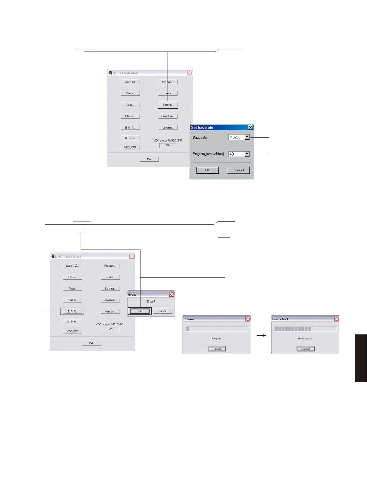
5. Click [Setting], and set the baud rate. (Fig. 4)
6. Click [E.P.R.], then the “Erase” screen appears. (Fig. 5)
7. Click [OK] to start writing. (Fig. 5)
5.[Setting]をクリックし、通信速度の設定を行い
ます。(Fig.4)
115200
40
Fig. 4
6.[E.P.R]をクリックすると、「Erase」が表示されま
す。(Fig.5)
7. [OK]をクリックして書き込みを開始します。(Fig.5)
Fig. 5
Writing being executed. /
書き込み中
A-S500/A-S300
19
A-S500/A-S300
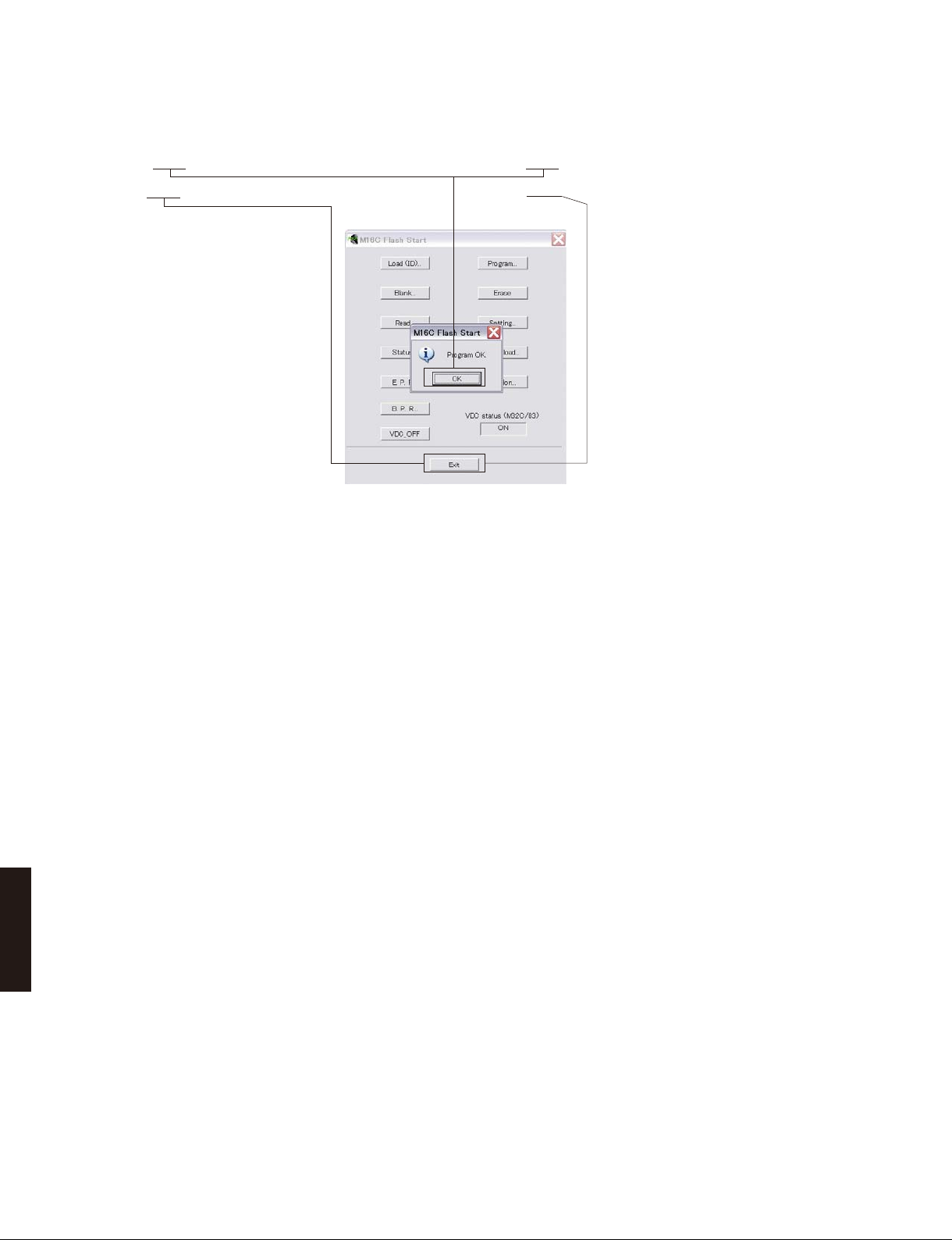
8. When writing of the firmware is completed, the
screen appears as shown below. (Fig. 6)
Click [OK]. (Fig. 6)
9. Click [Exit] to end FlashSta.exe. (Fig. 6)
10. Disconnect the power cable of this unit from the
AC outlet.
11. Remove the RS-232C conversion adaptor and
flexible flat cable from the writing port of this unit.
12. Connect the power cable of this unit to the AC
outlet, start up the self-diagnostic function and
check that the firmware version is the same
as written one. (See “Confirmation of firmware
version”)
8. ファームウェアの書き込みが完了すると、以下の
画面が表示されます。(Fig.6)
[OK]をクリックします。(Fig.6)
9.[Exit]をクリックして FlashSta.exe を終了します。
(Fig.6)
Fig. 6
10.本機の電源コードを AC コンセントから抜きます。
11.本機の書き込み用ポートから RS-232C 変換アダプ
ターとカード電線を取り外します。
12.本機の電源コードを AC コンセントに接続してダ
イアグを起動し、ファームウェアバージョンが書
き込まれたものと同じであることを確認します。
(「ファームウェアのバージョンの確認」参照)
A-S500/A-S300
20
A-S500/A-S300
■ SELF-DIAGNOSTIC FUNCTION /
A-S500 A-S300
This unit has self-diagnostic functions that provides the
following functions.
• Indication of firmware version
• Indication of power management switch status
• Indication of protection information
• Initialization
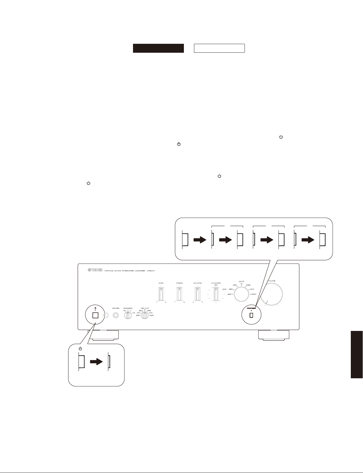
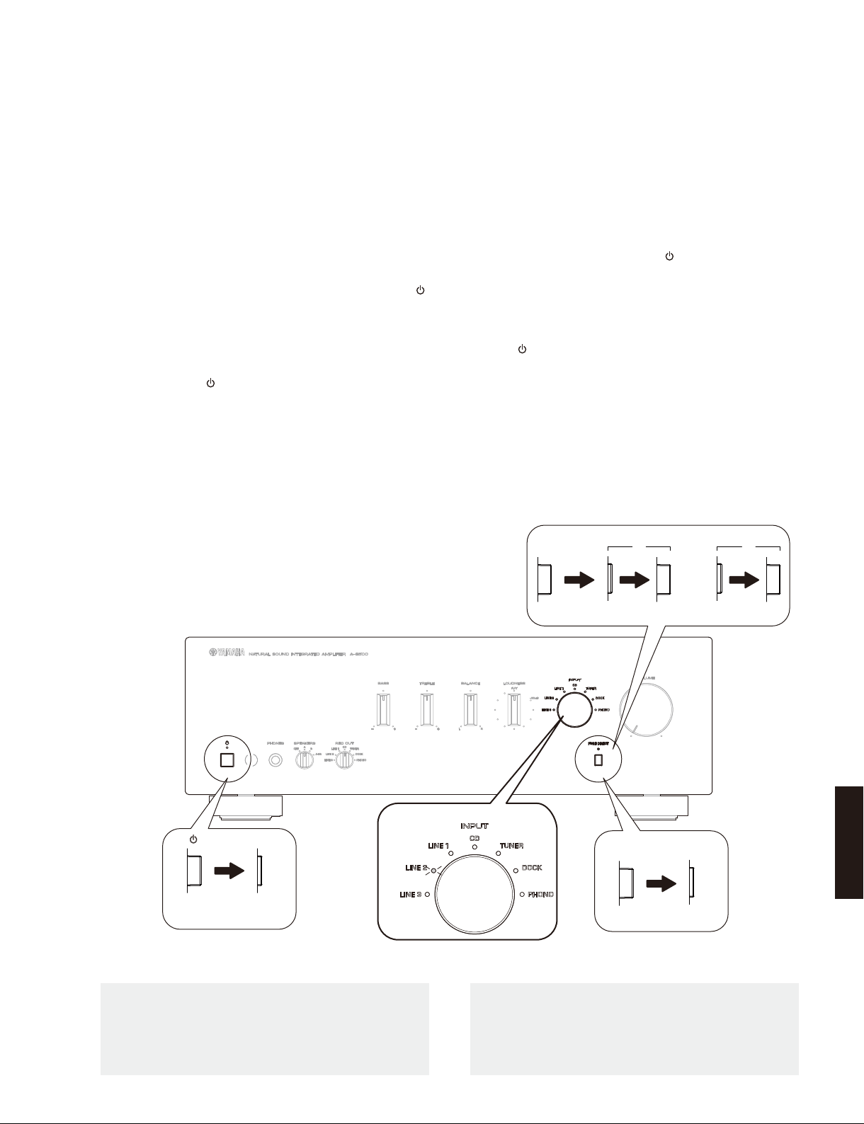
● Starting Self-Diagnostic Function
* Execute step 2 and 3 within 15 seconds after
executing step 1.
1. With the power to this unit turned on, press “
” (power) and “PURE DIRECT” switches to turn
them off respectively. (Fig. 1)
2. Repeat pressing “PURE DIRECT” switch to turn it
ON/OFF 3 times. (Fig. 1)
3. Press the “
power. (Fig. 1)
The self-diagnostic function mode is activated.
” (power) switch inward to turn on the
ダイアグ(自己診断機能)
本機には下記の機能をもつダイアグ(自己診断機能)が
あります。
・ ファームウェアのバージョン表示
・ POWERMANAGEMENT スイッチの状態表示
・ プロテクション情報の表示
・ 初期化
● ダイアグの起動
※ 1 の操作後 15 秒以内に2と3を操作してください。
1. 電源が入れられた状態で、“
“PUREDIRECT” スイッチを押し、それぞれ OFF に
します。(Fig.1)
2. “PUREDIRECT” スイッチを 3 回 ON/OFF します。
(Fig.1)
3. “
”(パワー)スイッチを押して電源を入れます。
(Fig.1)
ダイアグが起動します。
”(パワー)スイッチ、
3. " "(power) switch
OFF ON/
STANDBY
2. “PURE DIRECT” switch
OFF OFF
1
ON
ON
2
OFF
ON
3
OFF
A-S500/A-S300
Fig. 1
21
A-S500/A-S300
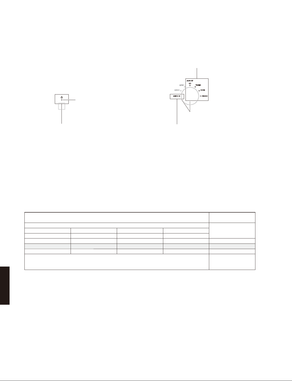
● Indication provided when SelfDiagnostic Function started
POWER ON indicator
パワーオンインジケーター
3. Indication of protection information
プロテクション情報の表示
● ダイアグ起動時の表示
1. Indication of firmware version
ファームウェアのバージョン表示
INPUT indicators
INPUT インジケーター
2. Indication of power management switch status
POWERMANAGEMENT スイッチの状態表示
Fig. 2
● Details of Indication
1. Indication of firmware version
The firmware version of the microprocessor (IC502
of the FUNCTION P.C.B.) is indicated in the binary
code (BCD) using the INPUT indicators.
INPUT indicators /
Binary number (BCD) [Light up: 1, Off: 0] /
CD TUNER DOCK PHONO
3
= 8) (22 = 4) (21 = 2) (20 = 1)
(2
0 1 1 0 V0006 (4+2=6)
0 1 1 1 V0007 (4+2+1=7)
1 0 0 0 V0008 (8)
INPUTインジケーター
2 進数(BCD)[点灯:1、消灯:0]
•
•
•
● 表示の詳細
1. ファームウェアのバージョン表示
マイコン(FUNCTIONP.C.B. の IC502)のファーム
ウェアバージョンが INPUT インジケーターを使っ
て 2 進数(BCD)で表示されます。
ファームウェアバージョン
Decimal number /
Firmware version /
10 進数
•
•
•
Fig. 3
2. Indication of power management switch
A-S500/A-S300
status
The status (ON/OFF) of the POWER MANAGEMENT
switch located on the rear panel is indicated
using the “LINE 3” INPUT indicator.
Light up: POWER MANAGEMENT switch is ON
2. POWERMANAGEMENT スイッチの状態表示
リアパネルにある POWERMANAGEMENT スイッ
チの状態(ON/OFF)が “LINE3”INPUT インジケー
ターを使って表示されます。
点灯: POWERMANAGEMENT スイッチ ON
消灯: POWERMANAGEMENT スイッチ OFF
Off: POWER MANAGEMENT switch is OFF
22
A-S500/A-S300
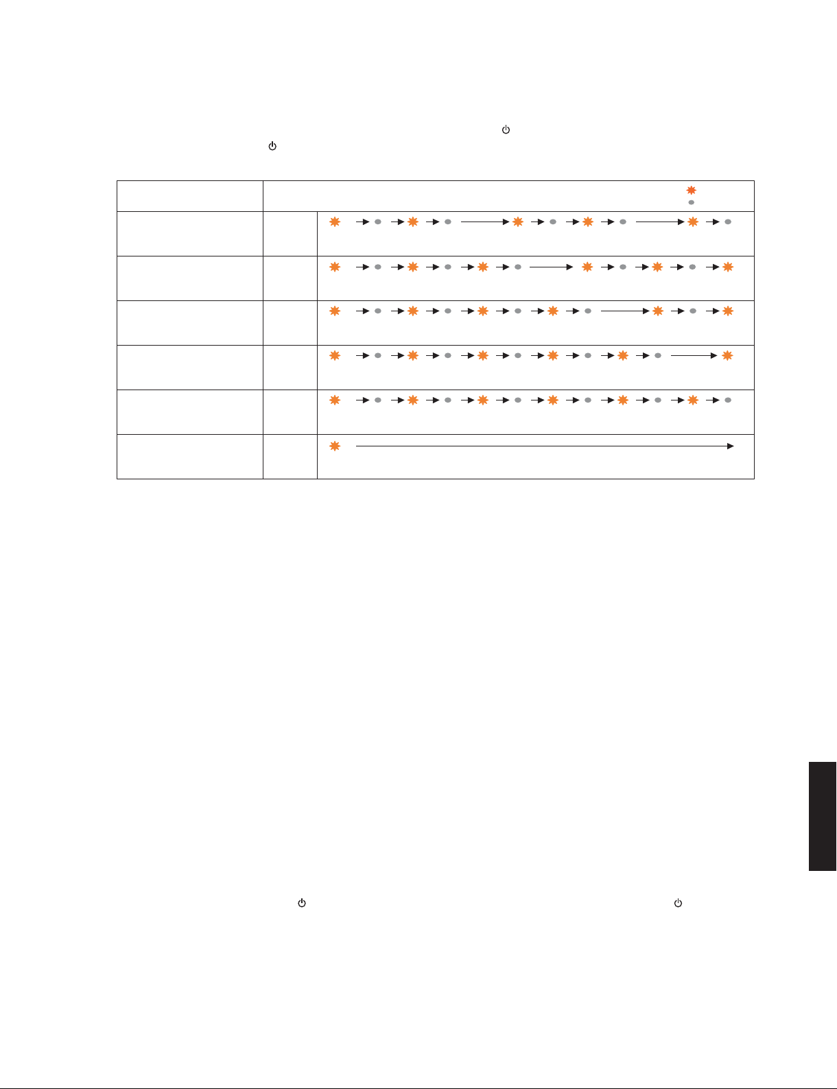
3. Indication of protection information
The protection information is indicated by the
flashing pattern of the “
Types of protection function /
プロテクションの種類
PS protection /
電源電圧プロテクション
I protection /
過電流プロテクション
DC protection /
DC電圧プロテクション
TMP protection L/R ch /
温度プロテクションL/Rch
APD (Automatic Power Down) /
パワーマネージメント
(no protection function) /
正常(プロテクション無し)
Normal
”(POWER ON) indicator.
Flashing 2 /
点滅2
Flashing 3 /
点滅3
Flashing 4 /
点滅4
Flashing 5 /
点滅5
Flashing 6 /
点滅6
Lit up/
点灯
500mS 500mS 500mS 1000mS 1000mS500mS 500mS 500mS 500mS
500mS 500mS 500mS 500mS 500mS 1000mS 500mS500mS 500mS 500mS
500mS 500mS 500mS 500mS 500mS 500mS 500mS 500mS 500mS
500mS 500mS 500mS 500mS 500mS 500mS 500mS 500mS 500mS
500mS 500mS 500mS 500mS 500mS 500mS 500mS 500mS 500mS 500mS 500mS
3. プロテクション情報の表示
“ ” ( パワーオン ) インジケーターの点滅パターン
により、プロテクション情報を表示します。
MAIN ZONE indicator flashing pattern /
MAINZONEインジケーターの点滅パターン
Continuous
: Lit / 点灯
: Off / 消灯
1000mS
1000mS
PS (Power Supply) protection
Cause: The voltage in the power supply
section is abnormal.
Normal value: 2.357 to 3.257V
Detection port: PRV (FUNCTION P.C.B. 93 pin of
the microprocessor IC502)
Detected at: ACL, ±15, +5S
I protection L/Rch
Cause: Excess current flow into amplifier.
Speaker terminal shorted. (*)
Normal value: LOW (0V)
Detection port: PRI (FUNCTION P.C.B. 73 pin of
the microprocessor IC502)
Detected at: PR I (Amplifier output L/Rch of
MAIN P.C.B.)
* If the protection function works due to shortage
at the speaker terminal, the power turns off at
the excess current protection L/Rch.
However, pressing the “
”(power) switch for
OFF/ON, all INPUT indicators flash 5 times
and the power to turn on.
Fig. 4
電源電圧プロテクション
原因: 電源部の電圧が異常。
正常値: 2.357 〜 3.257V
検出ポート: PRV(FUNCTION P.C.B. マイコン
IC502 の 93 ピン)
検出先: ACL、± 15、+5S
過電流プロテクション L/Rch
原因: アンプ部に過電流が流れた。
スピーカー端子をショートした。
(※)
正常値: LOW(0V)
検出ポート: PRI(FUNCTIONP.C.B.:マイコン
IC502 の 73 ピン)
検出先: PRI(MAINP.C.B. のアンプ出力 L/
Rch)
※ スピーカー端子のショートでプロテクション
が働いた場合、過電流プロテクション L/Rch
で電源を切ります。ただし“
”(パワー)スイッ
チを OFF/ON すると、すべての INPUT インジ
ケーターが 5 回点滅して電源が入ります。
A-S500/A-S300
23

A-S500/A-S300
DC voltage protection
Cause: Abnormal DC voltage of amplifier
output.
Normal value: 0.947 to 2.517V
Detection port: PRD (FUNCTION P.C.B. 89 pin of
the microprocessor IC502)
Detected at: Amplifier output L/Rch of MAIN
P.C.B.
THM protection L/Rch
Cause: Abnormal temperature of heat
sink.
Normal value: 0.20 to 1.66V
Detection port: THML (FUNCTION P.C.B. 84 pin
of the microprocessor IC502)
THMR (FUNCTION P.C.B. 83 pin
of the microprocessor IC502)
Detected at: THML (Heat sink temperature
detection Lch IC101 of the MAIN
P.C.B.)
THMR (Heat sink temperature
detection Rch IC102 of the MAIN
P.C.B.)
DC 電圧プロテクション
原因: アンプ出力の DC 電圧が異常。
正常値: 0.947 〜 2.517V
検出ポート: PRD(FUNCTIONP.C.B.:マイコン
IC502 の 89 ピン)
検出先: MAINP.C.B. のアンプ出力 L/Rch
温度プロテクション L/Rch
原因: ヒートシンクの温度が異常。
正常値: 0.20 〜 1.66V
検出ポート: THML(FUNCTIONP.C.B. マイコン
IC502 の 84 ピン)
THMR(FUNCTIONP.C.B.:マイコ
ン IC502 の 83 ピン)
検出先: THML(MAINP.C.B. のヒートシン
ク温度検出 LchIC101)
THMR(MAINP.C.B. のヒートシン
ク温度検出 RchIC102)
● Canceling Self-Diagnostic Function
To keep memory of the back-up IC preserved
Set the SPEAKERS selector to the OFF, B or A+B
position and press the “
the power. (Fig. 6)
Self-diagnostic function is canceled.
To reserve initialization of the back-up IC
Set the SPEAKERS selector to the “A” position, press
the “
” (power) switch to turn off the power. (Fig. 6)
Self-diagnostic function is canceled with the initialization
reserved.
” (power) switch to turn off
● ダイアグの解除
バックアップ用 IC のメモリーを保持するには
SPEAKERS セレクターを OFF、B または A+B に設定し
て、“
”(パワー)スイッチを押して電源を切ります。
(Fig.6)
ダイアグが解除されます。
バックアップ用 IC の初期化を予約するには
SPEAKERS セレクターを A に設定して、“
スイッチを押して電源を切ります。(Fig.6)
初期化が予約された状態でダイアグが解除されます。
”(パワー)
A-S500/A-S300
24
A-S500/A-S300
● Starting in the Protection Cancel mode
If the protection function works and causes hindrance
to trouble shoot, cancel the protection function as
described below, and it will be possible to enter the
self-diagnostic function mode.
(The protection functions other than the excess
current detect function will be disabled.)
* Execute step 2 and 3 within 15 seconds after
executing step 1.
1. With the power to this unit turned on, press “
(power) and “PURE DIRECT” switches to turn them
off respectively. (Fig. 5)
2. Repeat pressing “PURE DIRECT” switch to turn it
ON/OFF 6 times. (Fig. 5)
3. Press the “
power. (Fig. 5)
4. Press the “PURE DIRECT” switch inward to the
ON position. (Fig. 5)
After a few seconds, the self-diagnostic function
mode is activated with the protection functions
disabled.
In this mode, the “LINE 2” INPUT indicator flashes
to indicate that the mode is self-diagnostic
function mode with the protection functions
disabled. (Fig. 5)
” (power) switch inward to turn on the
● プロテクション解除モードでの起動
プロテクションが動作することにより、故障箇所の
診断に支障をきたすような場合は、次の方法により
プロテクションを解除した状態でダイアグモードに
入ることができます。
(過電流検出以外のプロテクション動作を解除する)
※ 1 の操作後 15 秒以内に2と3を操作してください。
1. 電源が入れられた状態で、“
“PUREDIRECT” スイッチを押し、それぞれ OFF に
”
します。(Fig.5)
2. “PUREDIRECT” スイッチを 6 回 ON/OFF します。
(Fig.5)
3. “
”(パワー)スイッチを押して電源を入れます。
(Fig.5)
4. “PUREDIRECT” スイッチを押して ON にします。
(Fig.5)
数秒後、プロテクション解除モードでダイアグが
起動します。
このモードでは “LINE2” INPUT インジケーター
が点滅し、プロテクションを解除した状態でのダ
イアグモードであることを知らせます。(Fig.5)
2. "PURE DIRECT" switch
”(パワー)スイッチ、
1
………
6
INPUT indicators
3. " "(power) switch
OFF ON/
STANDBY
CAUTION!
• Using this product with the protection function
disabled may cause further damage to this unit. Use
special care for this point when using this mode.
OFF OFF
ON
4. "PURE DIRECT" switch
OFF
ON
Fig. 5
注意!
・ プロテクションを解除した状態でのダイアグモード
は、危険な状態でもプロテクションが作動しないた
め、動作させると、本機を破壊することがあります。
このモードを使用する場合は十分注意してください。
ON
OFF
A-S500/A-S300
25
 Loading...