

Page 1
INTEGRATED AMPLIFIER
A-S3000
SERVICE MANUAL
IMPORTANT NOTICE
This manual has been provided for the use of authorized Yamaha Retailers and their service personnel.
It has been assumed that basic service procedures inherent to the industry, and more specifi cally Yamaha Products, are already known
and understood by the users, and have therefore not been restated.
WARNING:
IMPORTANT:
The data provided is believed to be accurate and applicable to the unit(s) indicated on the cover. The research, engineering, and service
departments of Yamaha are continually striving to improve Yamaha products. Modifi cations are, therefore, inevitable and specifi cations
are subject to change without notice or obligation to retrofi t. Should any discrepancy appear to exist, please contact the distributor's
Service Division.
WARNING:
IMPORTANT:
Failure to follow appropriate service and safety procedures when servicing this product may result in personal injury,
destruction of expensive components, and failure of the product to perform as specifi ed. For these reasons, we advise
all Yamaha product owners that any service required should be performed by an authorized Yamaha Retailer or the
appointed service representative.
The presentation or sale of this manual to any individual or fi rm does not constitute authorization, certifi cation or
recognition of any applicable technical capabilities, or establish a principle-agent relationship of any form.
Static discharges can destroy expensive components. Discharge any static electricity your body may have
accumulated by grounding yourself to the ground buss in the unit (heavy gauge black wires connect to this buss).
Turn the unit OFF during disassembly and part replacement. Recheck all work before you apply power to the unit.
A-S3000
■ CONTENTS
TO SERVICE PERSONNEL ............................................ 2
FRONT PANELS .............................................................3
REAR PANELS ........................................................... 4–6
REMOTE CONTROL PANEL .......................................... 7
SPECIFICATIONS /
INTERNAL VIEW ............................................................ 9
SERVICE PRECAUTIONS /
DISASSEMBLY PROCEDURES /
UPDATING FIRMWARE /
ファームウェアのアップデート
SELF-DIAGNOSTIC FUNCTION /
ダイアグ(自己診断機能)
101274
参考仕様
.....................................7–8
サービス時の注意事項
分解手順
............................21–25
.....................................26–31
...........10–20
....... 9
AMPLIFIER ADJUSTMENT /
IC DATA ...................................................................35–40
PIN CONNECTION DIAGRAMS ................................... 41
BLOCK DIAGRAMS ................................................42–43
WIRING DIAGRAMS ...............................................44–45
PRINTED CIRCUIT BOARDS .................................46–64
SCHEMATIC DIAGRAMS .......................................65–71
REPLACEMENT PARTS LIST ................................ 73–99
REMOTE CONTROL ...................................................100
アンプ調整
............... 32–34
P.O.Box 1, Hamamatsu, Japan
'13.10
Page 2
A-S3000
■ TO SERVICE PERSONNEL
1. Critical Components Information
Components having special characteristics are marked ⚠ and
must be replaced with parts having specifications equal to those
originally installed.
2. Leakage Current Measurement (For 120V Models Only)
When service has been completed, it is imperative to verify
that all exposed conductive surfaces are properly insulated
from supply circuits.
• Meter impedance should be equivalent to 1500 ohms shunted
by 0.15 F.
A-S3000
For U model
WALL
OUTLET
• Leakage current must not exceed 0.5mA.
• Be sure to test for leakage with the AC plug in both polarities.
EQUIPMENT
UNDER TEST
INSULATING
TABLE
AC LEAKAGE
TESTER OR
EQUIVALENT
“CAUTION”
“F1: FOR CONTINUED PROTECTION AGAINST RISK OF FIRE, REPLACE ONLY WITH SAME TYPE 10A, 125V
FUSE.”
For C model
CAUTION
F1: REPLACE WITH SAME TYPE 10A, 125V FUSE.
ATTENTION
F1: UTILISER UN FUSIBLE DE RECHANGE DE MÉME TYPE DE 10A, 125V.
WARNING: CHEMICAL CONTENT NOTICE!
This product contains chemicals known to the State of California to cause cancer, or birth defects or other reproductive
harm.
DO NOT PLACE SOLDER, ELECTRICAL/ELECTRONIC OR PLASTIC COMPONENTS IN YOUR MOUTH FOR ANY REASON
WHATSOEVER!
Avoid prolonged, unprotected contact between solder and your skin! When soldering, do not inhale solder fumes or
expose eyes to solder/flux vapor!
If you come in contact with solder or components located inside the enclosure of this product, wash your hands before
handling food.
About lead free solder /
All of the P.C.B.s installed in this unit and solder joints are
soldered using the lead free solder.
Among some types of lead free solder currently available,
it is recommended to use one of the following types for
the repair work.
• Sn + Ag + Cu (tin + silver + copper)
• Sn + Cu (tin + copper)
• Sn + Zn + Bi (tin + zinc + bismuth)
Caution:
As the melting point temperature of the lead free solder
is about 30°C to 40°C (50°F to 70°F) higher than that of
the lead solder, be sure to use a soldering iron suitable
to each solder.
無鉛ハンダについて
本機に搭載されているすべての基板およびハンダ付けに
よる接合部は無鉛ハンダでハンダ付けされています。
無鉛ハンダにはいくつかの種類がありますが、修理時に
は下記のような無鉛ハンダの使用を推奨します。
Sn+Ag+Cu(錫+銀+銅)
Sn+Cu(錫 + 銅)
Sn+Zn+Bi(錫 + 亜鉛 + ビスマス)
注意:
無鉛ハンダの融点温度は通常の鉛入りハンダに比べ 30 〜
40℃程度高くなっていますので、それぞれのハンダに合っ
たハンダごてをご使用ください。
2
Page 3
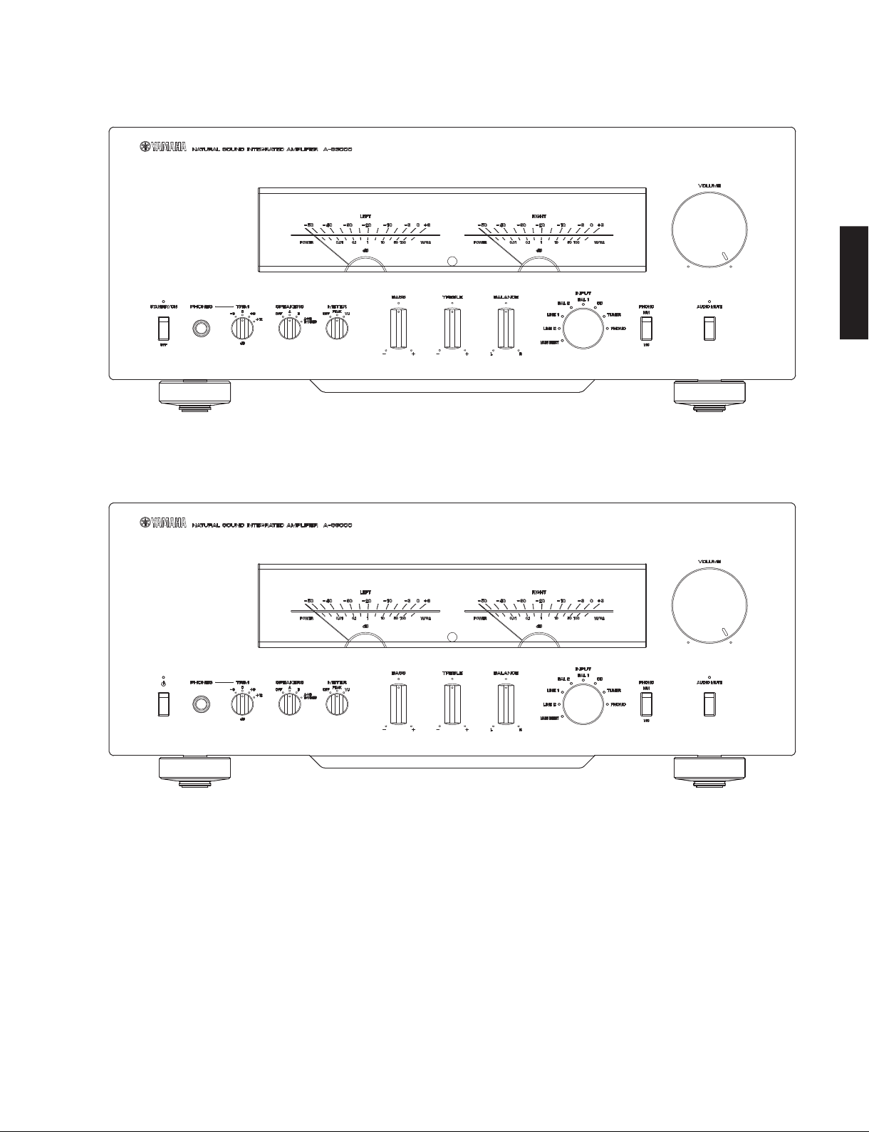
■ FRONT PANELS
U, K, A, B, G, L, V, J models
A-S3000
A-S3000
T model
3
Page 4
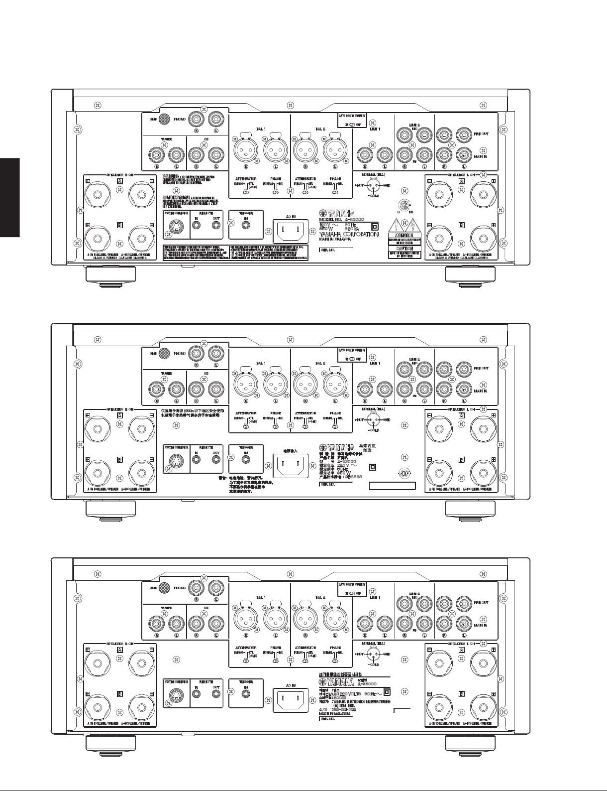
A-S3000
A-S3000
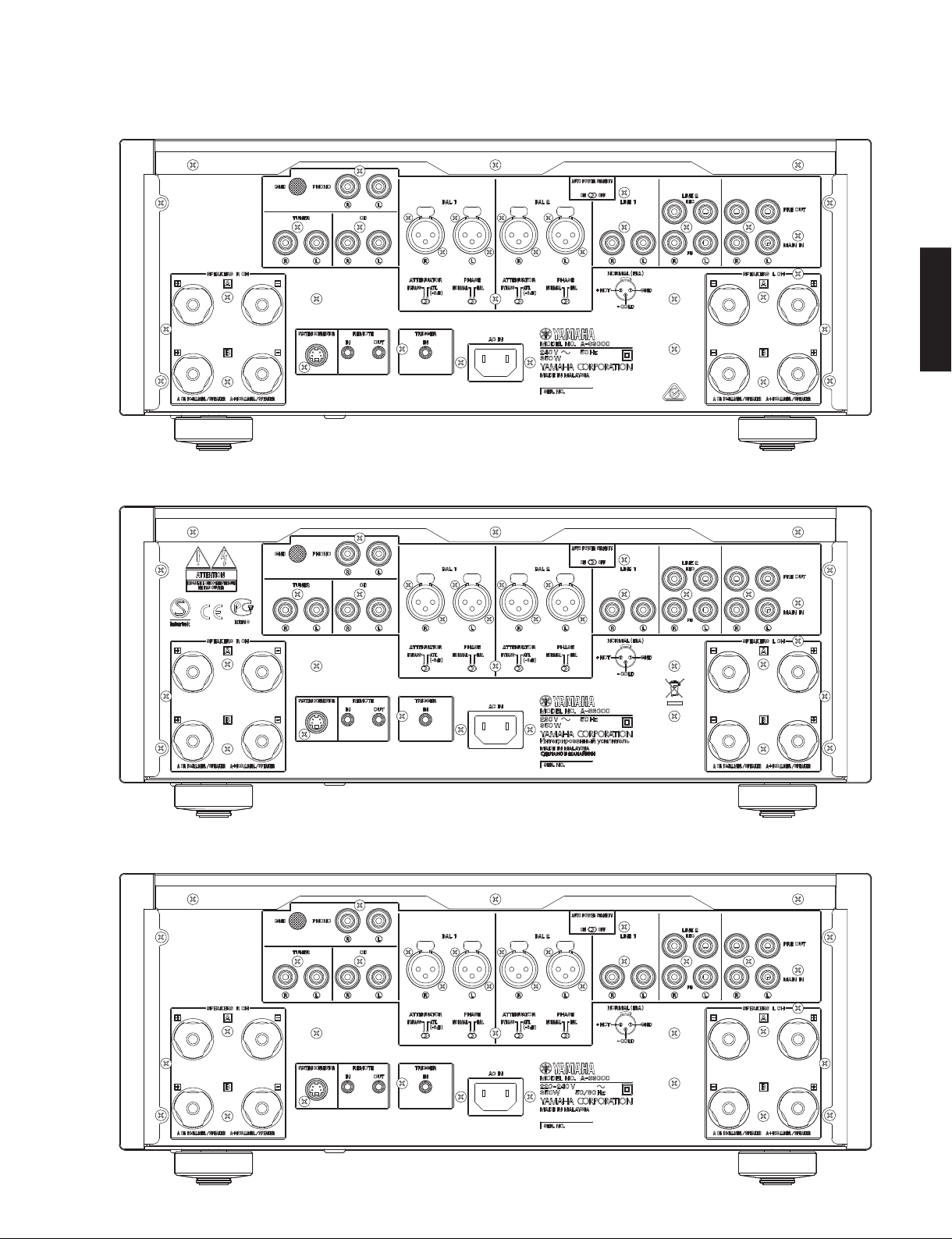
■ REAR PANELS
U model
T model
4
K model
Page 5
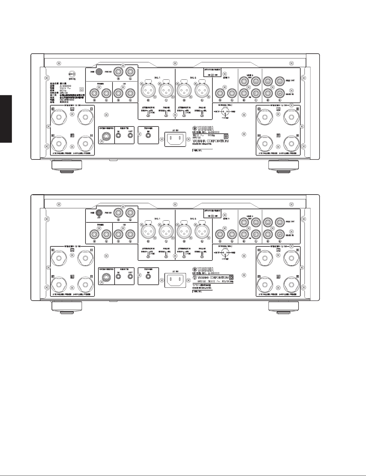
A model
B, G models
A-S3000
A-S3000
L model
5
Page 6
A-S3000
A-S3000
V model
J model
6
Page 7
A-S3000
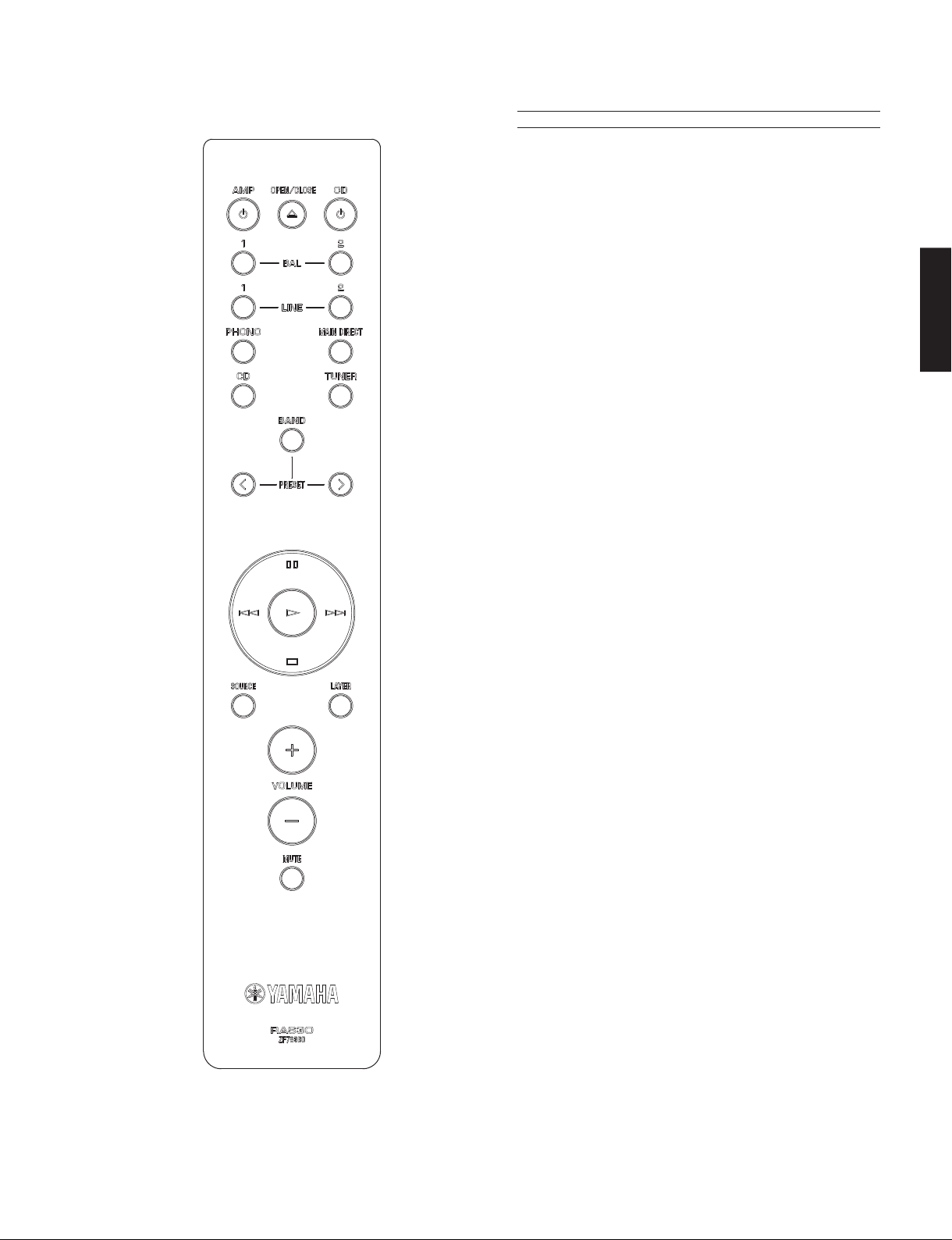
■ REMOTE CONTROL PANEL
RAS30
■ SPECIFICATIONS /
■ Audio Section /
Rated Output Power /
8 ohms ......................................................................100 W + 100 W
4 ohms ......................................................................150 W + 150 W
Dynamic Power Per Channel /
8 ohms ......................................................................120 W + 120 W
6 ohms ......................................................................150 W + 150 W
4 ohms ......................................................................200 W + 200 W
2 ohms ......................................................................300 W + 300 W
Dynamic Headroom /
8 ohms ..................................................................................0.79 dB
Maximum Power Per Channel (1 kHz, 0.7 % THD) [B, G models]
4 ohms ......................................................................170 W + 170 W
IEC Output Power (1 kHz, 0.02 % THD) [B, G models]
8 ohms ......................................................................105 W + 105 W
Maximum Effective Output Power /
(1 kHz, 10 % THD) [T, K, B, L, V, J models]
8 ohms ......................................................................130 W + 130 W
4 ohms ......................................................................210 W + 210 W
Power Bandwidth /
8 ohms .....................................................................10 Hz to 60 kHz
Damping Factor /
8 ohms ........................................................................... 250 or more
Input Sensitivity/Input Impedance /
(1 kHz, 10 % THD)
PHONO (MC) ................................................. 100 µVrms / 50 ohms
CD, etc. ....................................................... 200 mVrms / 47 k-ohms
MAIN IN ............................................................. 1 Vrms / 47 k-ohms
BAL (balanced) 1, 2 ................................. 200 mVrms / 100 k-ohms
Maximum Power /
[T, L, V, J models]
8 ohms ......................................................................120 W + 120 W
4 ohms ......................................................................190 W + 190 W
Maximum Input Signal Voltage /
PHONO (0.003 % THD) (MC) ......................................... 2.3 mVrms
CD, etc. (0.5 % THD) ..................................................... 2.80 mVrms
BAL (balanced) 1, 2 (0.5 % THD)
BYPASS ....................................................................... 2.80 mVrms
ATT. (-6 dB) .................................................................5.60 mVrms
Rated Output Voltage/Output Impedance /
定格出力電圧/出力インピーダンス
REC OUT ................................................... 200 mVrms / 1.5 k-ohms
PRE OUT ........................................................ 1.0 Vrms / 1.5 k-ohms
Headphone Jack Rated Output Power /
(1 kHz, 32 ohms, 0.2 % THD)
CD, etc. ...................................................................70 mW + 70 mW
Frequency Response /
CD, etc. (5 Hz to 100 kHz) ............................................... +0 / -3 dB
オーディオ部
(20 Hz to 20 kHz, 0.07 % THD)
定格出力
ダイナミックパワー
ダイナミックヘッドルーム
出力帯域幅
ダンピングファクタ
(MM) ............................................. 2.5 mVrms / 47 k-ohms
最大出力
(20 Hz to 20 kHz) ............................................ +0 / -0.3 dB
(0.1 % THD, 45 W / MAIN L/R drive)
(JEITA) (1 kHz, 10 % THD)
最大許容入力電圧
(MM) .......................................... 50 mVrms
周波数特性
参考仕様
(IHF)
実用最大出力
(1 kHz)
入力感度/入力インピーダンス
(JEITA)
(1 kHz)
ヘッドホン定格出力
A-S3000
7
Page 8
A-S3000
Deviations from RIAA Equalizer /
PHONO (MC) ...................................................................... ±0.5 dB
(MM) ..................................................................... ±0.5 dB
Total Harmonic Distortion /
PHONO (MC) to REC OUT (1.2 Vrms) .................................. 0.02 %
(MM) to REC OUT (1.2 Vrms) ...............................0.005 %
CD, etc. to SP OUT (50 W/8 ohms) .....................................0.025 %
BAL (balanced) 1, 2 to SP OUT (50 W/8 ohms) ..................0.025 %
A-S3000
Signal to Noise Ratio /
PHONO (MC) (Input shorted, 500 Vrms) ..............................85 dB
(MM) (Input shorted, 5 mVrms) .................................93 dB
CD, etc. (Input shorted, 200 mVrms) .....................................103 dB
Residual Noise /
........................................................................................... 33 Vrms
Channel Separation /
PHONO (MC) (Input shorted, Vol: -30 dB)
...................................................... 66 dB or more / 77 dB or more
(MM) (Input shorted, Vol: -30 dB)
...................................................... 90 dB or more / 77 dB or more
CD, etc. (Input 5.1 k-ohms terminated)
...................................................... 74 dB or more / 54 dB or more
Tone Control Characteristics /
Bass
Boost/Cut ..............................................................±9 dB, at 50 Hz
Turnover frequency .............................................................350 Hz
Treble
Boost/Cut ............................................................±9 dB, at 20 kHz
Turnover frequency ............................................................ 3.5 kHz
信号対雑音比
残留ノイズ
チャンネルセパレーション
RIAA イコライザ偏差
全高調波歪率
(IHF-A network)
トーンコントロール特性
(20 Hz to 20 kHz)
(IHF-A network)
(1 kHz/10 kHz)
Weight / 質量
............................................................................. 24.6 kg (54.2 lbs.)
Finish /
K, A, G, L, V models ....................................Black/Dark brown color
U, T, A, B, G, L, V, J models ..........................Black/Piano black color
K, A, G, L, V models ..............................................Silver/Birch color
U, T, A, B, G, L, V, J models ..........................Silver/Piano black color
Accessories /
Remote control ..............................................................................x 1
Battery (R03, AAA, UM-4) .............................................................x 2
Power cable (2.0 m) (U, T, K, A, B, G, L, V models) ....................x 1
* Specifications are subject to change without notice.
※ 参考仕様および外観は、製品の改良のため予告なく変更すること
があります。
U .......................U.S.A. model
T .................... Chinese model
K .....................Korean model
A ................Australian model
B ...................... British model
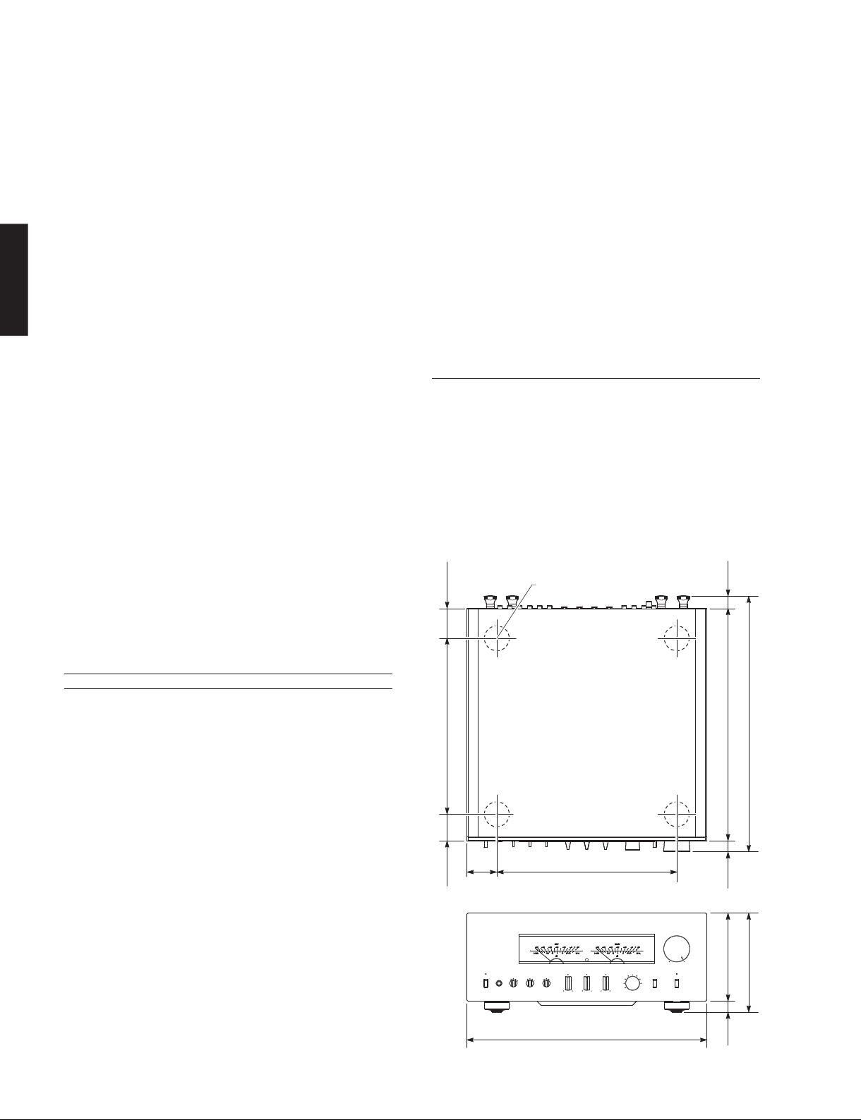
• DIMENSIONS /
54
(2-1/8")
仕上げ
Color: Front and top panels / Side panel
付属品
(1.5 m) (J model) ....................................................x 1
G .................European model
L .................Singapore model
V ..................... Taiwan model
J ..................Japanese model
寸法図
Top view
ø 45
23
(7/8")
■ General /
Power Supply /
U model ..................................................................AC 120 V, 60 Hz
T model ................................................................... AC 220 V, 50 Hz
K model .................................................................. AC 220 V, 60 Hz
A model .................................................................. AC 240 V, 50 Hz
B, G models ............................................................ AC 230 V, 50 Hz
L model ...................................................... AC 220–240 V, 50/60 Hz
V model ................................................................... AC 110 V, 60 Hz
J model .............................................................. AC 100 V, 50/60 Hz
Power Consumption /
U model ......................................................................350 W/500 VA
T, K, A, B, G, L, V, J models .................................................... 350 W
Standby Power Consumption (reference data) /
待機時消費電力(参考値)
................................................................................................. 0.3 W
Maximum Power Consumption (1 kHz, 8 ohms, 10 % THD) [V model]
................................................................................................ 700 W
Dimensions (W x H x D) /
............................... 435 x 180 x 464 mm (17-1/8" x 7-1/8" x 18-1/4")
総合
電源電圧
消費電力
寸法(幅 × 高さ × 奥行き)
8
319 (12-1/2")
48
55
(1-7/8")
(2-1/8")
Front view
325 (12-3/4")
435 (17-1/8")
421 (16-5/8")
464 (18-1/4")180 (7-1/8")
20
(3/4")
160 (6-1/4")
20
(3/4")
Unit: mm (inch)
単位:mm(インチ)
Page 9
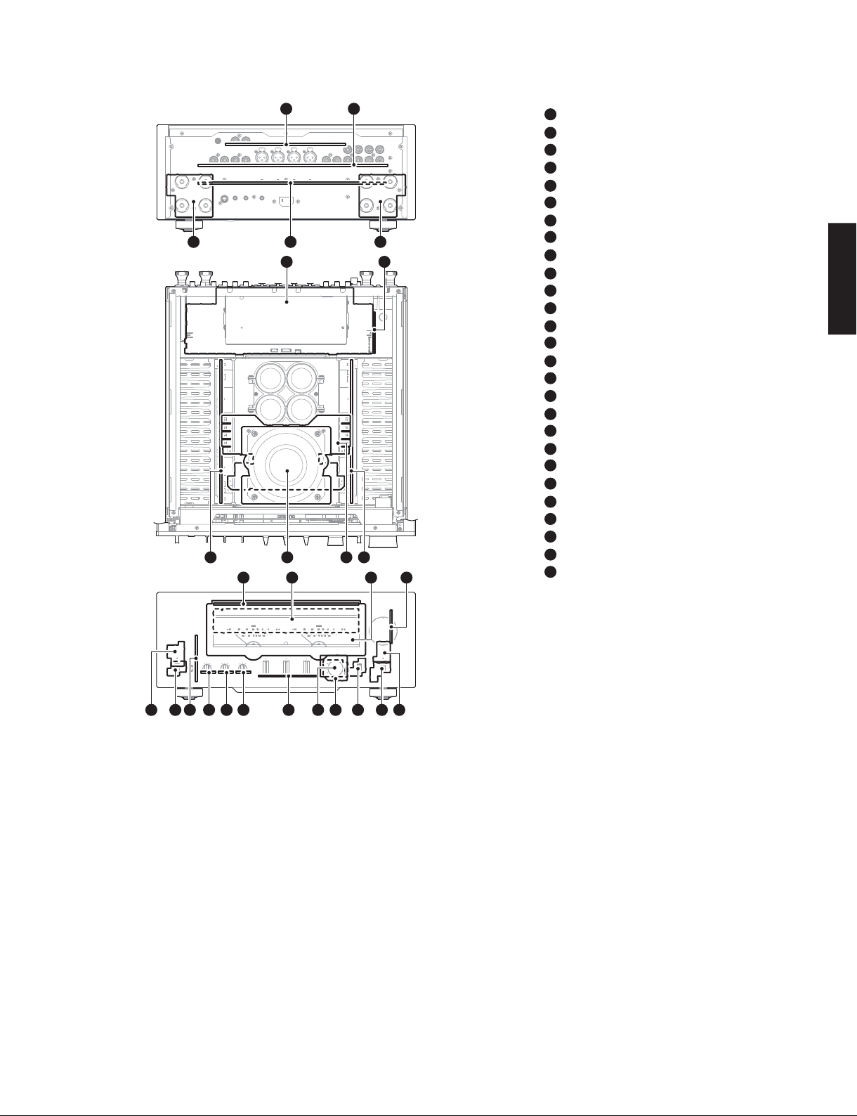
■ INTERNAL VIEW
Rear view
Top view
Front view
12 13
A-S3000
1
4
6
10
2
35
7
8
911
1514
1
INPUT (2) P.C.B.
2
INPUT (1) P.C.B.
3
FRONT (16) P.C.B.
4
FUNCTION (2) P.C.B.
5
FRONT (15) P.C.B.
6
FUNCTION (1) P.C.B.
7
INPUT (3) P.C.B.
8
MAIN (1) P.C.B.
9
MAIN (3) P.C.B.
10
POWER TRANSFORMER
11
MAIN (2) P.C.B.
12
LED P.C.B.
13
FRONT (1) P.C.B.
14
METER UNIT
15
FRONT (2) P.C.B.
16
FRONT (3) P.C.B.
17
FRONT (5) P.C.B.
18
FRONT (6) P.C.B.
19
FRONT (4) P.C.B.
20
FRONT (7) P.C.B.
21
FRONT (8) P.C.B.
22
FRONT (9) P.C.B.
23
FRONT (10) P.C.B.
24
FRONT (11) P.C.B.
25
FRONT (12) P.C.B.
26
FRONT (14) P.C.B.
27
FRONT (13) P.C.B.
A-S3000
17182122232426 19
16202527
■ SERVICE PRECAUTIONS /
サービス時の注意事項
Safety measures
• Some internal parts in this product contain high voltages
and are dangerous.
Be sure to take safety measures during servicing, such
as wearing insulating gloves.
• Note that the capacitors indicated below are dangerous
even after the power is turned off because an electric
charge remains and a high voltage continues to exist
there.
Before starting any repair work, connect a discharging
resistor (5 k-ohms/10 W) to the terminals of each
capacitor indicated below to discharge electricity.
The time required for discharging is about 30 seconds
per each.
C317 to C320 on MAIN (3) P.C.B.
For details, refer to “PRINTED CIRCUIT BOARDS”.
安全対策
・ この製品の内部には高電圧部分があり危険です。修理
の際は、絶縁性の手袋を使用するなどの安全対策を
行ってください。
・ 下記のコンデンサには電源を OFF にした後も電荷が残
り、高電圧が維持されており危険です。
修理作業前に放電用抵抗(5k Ω /10W)を下記の各コ
ンデンサの端子間に接続して放電してください。
放電所用時間は各々約 30 秒間です。
MAIN(3)P.C.B. の C317 〜 C320
詳しくは “PRINTEDCIRCUITBOARDS” を参照してくだ
さい。
9
Page 10
A-S3000
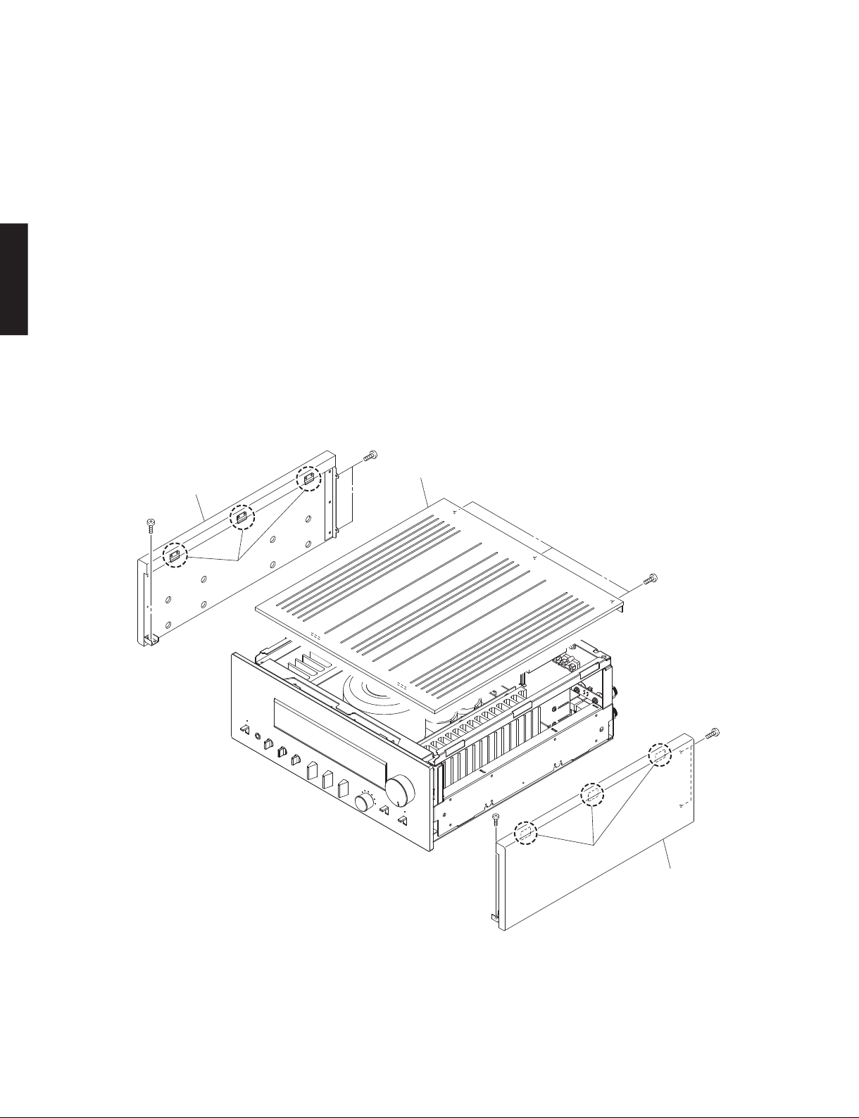
■ DISASSEMBLY PROCEDURES /
(Remove parts in the order as numbered.)
Disconnect the power cable from the AC outlet.
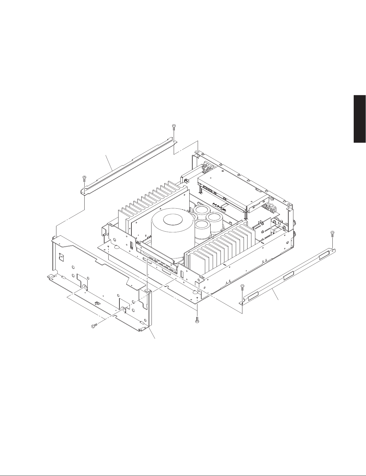
1. Removal of Top Panel
a. Remove 3 screws (①). (Fig. 1)
b. Remove the top panel. (Fig. 1)
2. Removal of Side Panel L and Side Panel R
a. Remove 3 screws (②). (Fig. 1)
b. Lift the side panel L a little, release hooks at 3 locations
A-S3000
and then remove the side panel L. (Fig. 1)
c. Remove 3 screws (③). (Fig. 1)
d. Lift the side panel R a little, release hooks at 3 locations
and remove the side panel R. (Fig. 1)
Side panel L
サイドパ ネル L
②
分解手順
(番号順に部品を外してください。)
AC 電源コンセントから、電源コードを抜いてください。
1. トップパネルの外し方
a. ①ネジ 3 本を外します。(Fig.1)
b. トップパネルを外します。(Fig.1)
2. サイドパネル L、サイドパネル R の外し方
a. ②のネジ 3 本を外します。(Fig.1)
b. サイドパネル L を少し持ち上げ、3 ヶ所のフックを外
c. ③のネジ 3 本を外します。(Fig.1)
d. サイドパネル R を少し持ち上げ、3 ヶ所のフックを外
②
Top panel
トップ パ ネ ル
し、サイドパネル L を外します。(Fig.1)
し、サイドパネル R を外します。(Fig.1)
Hook
フック
Fig. 1
③
Hook
フック
①
③
Side panel R
サイドパ ネル R
10
Page 11
A-S3000
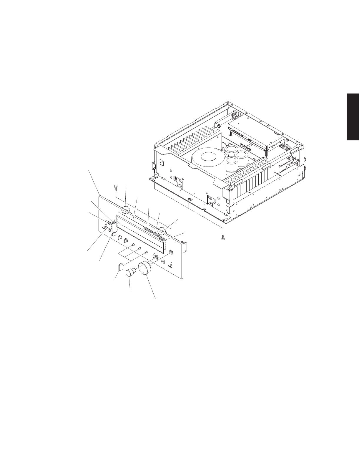
3. Removal of Front Panel Unit
a. Remove 5 screws (④). (Fig. 2)
b. Remove CB401, CB403, CB405, CB406 and CB410.
(Fig. 2)
c. Remove the front panel unit. (Fig. 2)
Front panel unit
フロントパネルユ ニット
Hook
④
フック
CB403
CB401
FRONT (1) P.C.B.
CB406
CB410
3. フロントパネルユニットの外し方
a. ④のネジ 5 本を外します。(Fig.2)
b. CB401、CB403、CB405、CB406、CB410 を外します。
(Fig.2)
c. フロントパネルユニットを外します。(Fig.2)
A-S3000
Hook
フック
FRONT (14) P.C.B.
FRONT (12) P.C.B.
TONE CONTROL knob unit
TONECONTROL つまみ
INPUT knob unit
INPUT つまみ
CB405
④
VOLUME knob unit
VOLUME つまみ
Fig. 2
11
Page 12
A-S3000
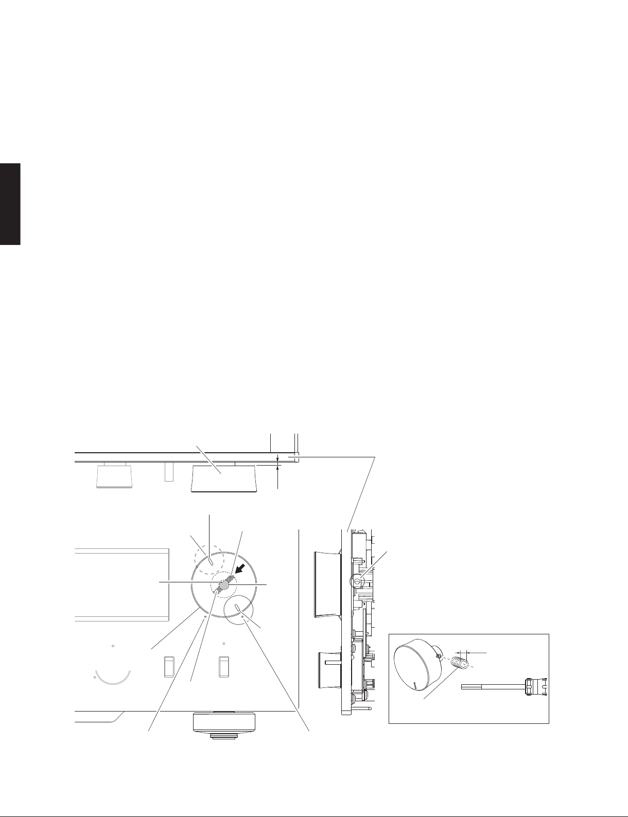
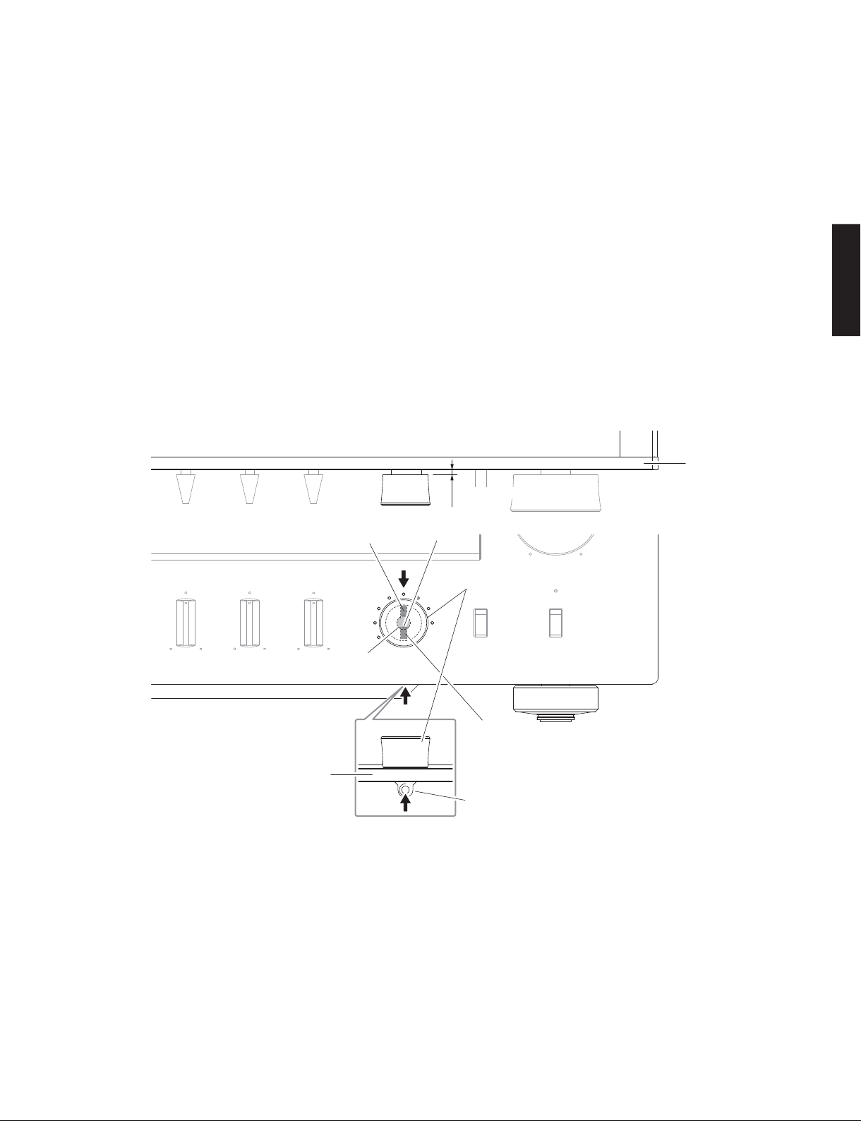
● When installing the knob unit
* Prepare a hexagonal screwdriver (2 mm) for
installation of knob unit.
When installing the VOLUME knob unit:
a. Turn the VOLUME (VR401) clockwise fully. (Fig. 3)
b. Match the pointer in the VOLUME knob unit with
the “VOLUME MAX.” position and install it in that
state. (Fig. 3)
* At this time, do not tighten the lock set screw.
c. Keep about 0.5 mm to 0.75 mm clearance from
A-S3000
the front panel to VOLUME knob unit. (Fig. 3)
d. Tighten the lock set screw. (Fig. 3)
e. Match the pointer in the VOLUME knob unit with
the position about -180° from the “VOLUME MAX”
position. (Fig. 3)
f. Tighten the lock set screw. (Fig. 3)
g. After installation, perform following checks.
• Turn the VOLUME knob unit both directions to
check that it does not rub against the front panel.
• Turn the VOLUME knob unit clockwise fully and
check that the pointer in it matches with the
“VOLUME MAX.” position.
• Turn the VOLUME knob unit counterclockwise
● つまみを取り付ける場合
※ つまみを取り付ける場合、6 角ドライバー(2
mm)を準備します。
VOLUME つまみを取り付ける場合:
a. VOLUME(VR401)を右いっぱいに回します。(Fig.3)
b. VOLUME つまみの指標を “VOLUMEMAX.” の位置
に合わせ、取り付けます。(Fig.3)
※ このとき、まだ止めネジは締めません。
c. フロントパネルから VOLUME つまみまで 0.5 〜
0.75mm 程度隙間をあけます。(Fig.3)
d. 止めネジを締めます。(Fig.3)
e. VOLUME つまみの指標を “VOLUMEMAX.” の位置
から約 -180°の位置に合わせます。(Fig.3)
f. 止めネジを締めます。(Fig.3)
g. 取り付け後、次の動作を確認します。
・ VOLUME つまみを左右に回し、フロントパネル
に擦っていないか?
・ VOLUME つまみを右いっぱいに回し、VOLUME
つまみの指標が “VOLUMEMAX.” の位置に合う
か?
・ VOLUME つまみを左いっぱいに回し、VOLUME
つまみの指標が “VOLUMEMIN.” の位置に合う
か?
fully and check that the pointer in it matches
with the “VOLUME MIN.” position.
VOLUME knob unit
VOLUME つまみ
Position about -180° from “VOLUME MAX”
position
VOLUMEMAX.の位置から約 -180°の位置
Cut
カット位置
VOLUME knob unit
VOLUME つまみ
Lock set screw
止めネジ
Pointer
指標
Lock set screw
止めネジ
VR401
Pointer
指標
0.5–0.75 mm
Side view
Front panel
Install/remove the lock set screw at this position
on the back of the front panel.
フロントパネル裏側のこの箇所で止めネジの
取り外し/取り付けを行います 。
2mm
Lock set screw
止めネジ
Hexagonal screwdriver
6 角ドライバー
“VOLUME MIN.” position
VOLUMEMIN.位置
12
“VOLUME MAX.” position
VOLUMEMAX.位置
Fig. 3
Page 13
A-S3000
When installing the INPUT knob unit:
a. Turn the INPUT (SW403) so that the cut in it comes
at the under. (Fig. 4)
b. Install the INPUT knob unit with its lock set screw
positioned at the under. (Fig. 4)
* At this time, do not tighten the lock set screw.
c. Keep about 0.5 mm to 0.75 mm clearance from
the front panel to INPUT knob unit. (Fig. 4)
d. Match the lock set screw position with the cut in
INPUT (SW403) and tighten the lock set screw.
(Fig. 4)
e. Turn the INPUT knob unit by 180 degrees (6 clicks)
and tighten another lock set screw. (Fig. 4)
f. After installation, perform following checks.
• Turn the INPUT knob unit in both directions to
check that it does not rub against the front panel.
INPUT つまみを取り付ける場合:
a. INPUT(SW403)のカット位置が下になるよう回
します。(Fig.4)
b. INPUT つまみの止めネジ位置を下にして取り付け
ます。(Fig.4)
※ このとき、止めネジは締めません。
c. フロントパネルからINPUT つまみまで0.5〜
0.75mm 程度隙間をあけます。(Fig.4)
d. INPUT(SW403)のカット位置に止めネジ位置を
合わせ、止めネジを締めます。(Fig.4)
e. INPUT つまみを 180°回転(6 クリック)させ、も
う 1 つの止めネジを締めます。(Fig.4)
f. 取り付け後、次の動作を確認します。
・ INPUT つまみを左右に回し、フロントパネルに
擦っていないか?
Front panel
0.5–0.75 mm
A-S3000
Lock set screw
Front panel
止めネジ
SW403
Bottom view
Cut
カット位置
INPUT knob unit
INPUT つまみ
Lock set screw
止めネジ
Install/remove the lock set screw at this position
on the back of the front panel.
フロントパネル裏側のこの箇所で止めネジの
取り外し/取り付けを行います 。
Fig. 4
13
Page 14
A-S3000
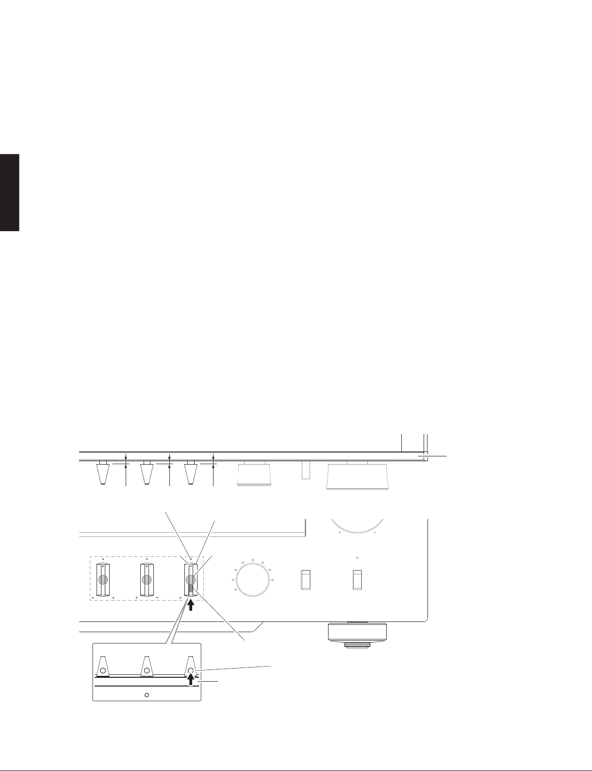
When installing the BASS, TREBLE and BALANCE
BASS、TREBLE、BALANCE つまみを取り付ける場合:
knob units:
* Use the same installation procedure for BASS,
TREBLE and BALANCE knob units.
Described here is installation of BALANCE knob
unit as an example.
a. Turn the BALANCE (VR403) in both directions and
set it to the center position. (Fig. 5)
* VR403 stops at the center position when it is
turned in both directions.
b. Match the pointer in the BALANCE knob unit with
A-S3000
the center position of BALANCE and install it in
that state. (Fig. 5)
* At this time, do not tighten the lock set screw.
c. Keep about 0.5 mm to 0.75 mm clearance from
the front panel to BALANCE knob unit. (Fig. 5)
d. Tighten the lock set screw of the BALANCE knob
unit. (Fig. 5)
e. After installation, perform following checks.
• Turn the BALANCE knob unit in both directions
to check that it does not rub against the front
panel.
※ BASS、TREBLE、BALANCE つまみの取り付け方法
はすべて同じです。
例として BALANCE つまみの取り付け方法を記載
します。
a. BALANCE(VR403)を左右に回し、中央の位置に
合わせます。(Fig.5)
※ 左右に回すと、中央の位置で一度止まります。
b. BALANCE つまみの指標を BALANCE 中央の位置に
合わせ、取り付けます。(Fig.5)
※ このとき、まだ止めネジは締めません。
c. フロントパネルから BALANCE つまみまで 0.5 〜
0.75mm 程度隙間をあけます。(Fig.5)
d. BALANCE つまみの止めネジを締めます。(Fig.5)
e. 取り付け後、次の動作を確認します。
・ BALANCE つまみを左右に回し、フロントパネ
ルに擦っていないか?
・ BALANCE つまみを左いっぱいに回し、BALANCE
つまみの指標が “BALANCEL” の位置に合うか?
・ BALANCE つまみを右いっぱいに回し、BALANCE
つまみの指標が “BALANCER” の位置に合うか?
• Turn the BALANCE knob unit counterclockwise
fully and check that the pointer in it matches with
the “BALANCE L” position.
• Turn the BALANCE knob unit clockwise fully
and check that the pointer in it matches with the
“BALANCE R” position.
Center position of “BALANCE” knob unit
BALANCEつまみの中央位置
Pointer
指標
Bottom view
0.5–0.75 mm
“BALANCE” knob unit
BALANCEつまみ
VR403
Lock set screw
止めネジ
Front panel
Front panel
Install/remove the lock set screw at this position
on the front of the front panel.
フロントパネル表側のこの箇所で止めネジの
取り外し/取り付けを行います 。
Fig. 5
14
Page 15
A-S3000
4. Removal of Sub-chassis
a. Remove 4 screws (⑤). (Fig. 6)
b. Remove the support top L and support top R. (Fig. 6)
c. Remove 4 screws (⑥). (Fig. 6)
d. Remove the sub-chassis. (Fig. 6)
⑤
Support top (L)
サポートトップ(L)
⑤
4. サブシャーシの外し方
a. ⑤のネジ 4 本を外します。(Fig.6)
b. サポートトップ L とサポートトップ R を外します。
(Fig.6)
c. ⑥のネジ 4 本を外します。(Fig.6)
d. サブシャーシを外します。(Fig.6)
A-S3000
⑥
⑤
⑤
Support top (R)
サポートトップ(R)
⑥
Sub-chassis
サブシャーシ
Fig. 6
15
Page 16

A-S3000
When checking the P.C.B.:
• Put a rubber sheet and cloth under the equipment.
Then place this unit on the cloth and check it. (Fig. 7)
• Connect the front panel unit to the chassis with a
ground lead or the like. (Fig. 7)
• Reconnect all cables (connectors) that have been
disconnected.
• When connecting the flexible flat cable, be careful with
P.C.B. をチェックをする場合には:
・ ゴムシートと布を敷き、その上に本機を置いてチェッ
クします。(Fig.7)
・ フロントパネルユニットをリード線等でシャーシに
接続してください。(Fig.7)
・ 外したケーブル(コネクター)をすべて接続します。
・ フラットケーブルを接続する際、極性に注意してく
ださい。
polarity.
A-S3000
Ground lead
アース 線
Chassis
シャーシ
16
Rubber sheet and cloth
ゴムシートと布
Front panel unit
フロントパネルユ ニット
Fig. 7
Page 17

A-S3000
5. Removal of Heatsink Unit L, Heatsink Unit R
and Power Unit
a. Remove 8 screws (⑦) and 16 screws (⑧). (Fig. 8)
b. Remove 5 screws (⑨) and disconnect 5 cables.
(Fig. 8)
c. Remove 2 screws (⑩) and then remove 2 push rivets.
(Fig. 8)
d. Remove CB1, CB101, CB201, CB305, CB306, CB502
and CB505. (Fig. 8)
e. Remove the heatsink unit L and heatsink unit R
together with the power unit. (Fig. 8)
Heatsink unit L
ヒートシンクユニットL
MAIN (3) P.C.B.
MAIN (2) P.C.B.
CB201
CB306
Power unit
パワーユニット
5. ヒートシンクユニット L、ヒートシンクユニット
R、パワーユニットの外し方
a. ⑦のネジ 8 本、⑧のネジ 16 本を外します。(Fig.8)
b. ⑨のネジ 5 本を外し、ケーブル 5 本を外します。
(Fig.8)
c. ⑩のネジ 2 本とプッシュリベット 2 個を外します。
(Fig.8)
d. CB1、CB101、CB201、CB305、CB306、CB502、CB505
を外します。(Fig.8)
e. ヒートシンクユニット L、ヒートシンクユニット R と
パワーユニットを一緒に外します。(Fig.8)
Heatsink unit R
MAIN (1) P.C.B.
ヒートシンクユニットR
CB101
Push rivet
プッシュリベット
A-S3000
⑨
⑨
W416
W415
W52
⑨
CB305
⑨
⑦
⑧
W414
⑨
W413
⑦
⑧
CB1
CB505
FUNCTION (1) P.C.B.
⑩
CB502
⑦
⑧
⑦
⑧
⑧
⑧
⑧
Fig. 8
17
Page 18

A-S3000
g. Remove 10 screws (⑪). (Fig. 9)
h. Remove the front frame. (Fig. 9)
i. Remove 10 screws (⑫). (Fig. 9)
j. Remove the rear frame. (Fig. 9)
k. Remove 4 screws (⑬). (Fig. 9)
l. Remove CB205, CB206, CB304 and CB308. (Fig. 9)
m. Remove the heatsink unit L together with the MAIN (2)
P.C.B. (Fig. 9)
n. Remove 4 screws (⑭). (Fig. 9)
o. Remove CB303. (Fig. 9)
p. Remove the heatsink unit R together with the MAIN (1)
A-S3000
P.C.B. (Fig. 9)
Heatsink unit L
ヒートシンクユニットL
CB205
MAIN (2) P.C.B.
g. ⑪のネジ 10 本を外します。(Fig.9)
h. フロントフレームを外します。(Fig.9)
i. ⑫のネジ 10 本を外します。(Fig.9)
j. リアフレームを外します。(Fig.9)
k. ⑬のネジ 4 本を外します。(Fig.9)
l. CB205、CB206、CB304、CB308 を外します。(Fig.9)
m.ヒートシンクユニット L と MAIN(2)P.C.B. を一緒に
外します。(Fig.9)
n. ⑭のネジ 4 本を外します。(Fig.9)
o. CB303 を外します。(Fig.9)
p. ヒートシンクユニット R と MAIN(1)P.C.B. を一緒に
外します。(Fig.9)
Rear frame
リアフレーム
⑫
⑫
Power unit
パワーユニット
⑫
⑫
⑪
⑪
Front frame
フロントフレーム
CB206
⑪
MAIN (3) P.C.B.
⑪
⑪
⑪
CB303
CB308
⑪
⑬
CB304
MAIN (1) P.C.B.
Fig. 9
⑭
⑫
⑫
⑫
Heatsink unit R
ヒートシンクユニットR
18
Page 19

A-S3000
When checking the P.C.B.:
• Put the rubber sheet and cloth over this unit. Then
place the P.C.B. slantingly on the cloth and check it.
(Fig. 10)
• Connect the front panel unit, heatsink unit L and
heatsink unit R to the chassis with a ground lead or
the like. (Fig. 10)
• Reconnect all cables (connectors) that have been
disconnected.
• When connecting the flexible flat cable, be careful with
polarity.
• It is also possible to check the power unit, heatsink
unit L and heatsink unit R from the bottom. (Fig. 11)
Power unit
パワーユニット
Heatsink unit R
Ground lead
アース 線
Heatsink unit L
ヒートシンクユニットL
ヒートシンクユニットR
P.C.B. をチェックをする場合には:
・ 本機の上にゴムシートと布を敷き、その上に P.C.B. を
斜めに置いてチェックします。(Fig.10)
・ フロントパネルユニットとヒートシンクユニット L、
ヒートシンクユニット R をリード線等でシャーシに
接続してください。(Fig.10)
・ 外したケーブル(コネクター)をすべて接続します。
・ フラットケーブルを接続する際、極性に注意してく
ださい。
・ パワーユニット、ヒートシンクユニット L、ヒート
シンクユニット R は底面からチェックすることもで
きます。(Fig.11)
Ground lead
アース 線
A-S3000
Rubber sheet and cloth
ゴムシートと布
ヒートシンクユニットR
Rubber sheet and cloth
ゴムシートと布
パワーユニット
Heatsink unit R
Front panel unit
フロントパネルユ ニット
Fig. 10
Power unit
Heatsink unit L
ヒートシンクユニットL
Fig. 11
19
Page 20

A-S3000
6. Removal of INPUT (2) P.C.B.
a. Remove 2 screws (⑮). (Fig. 12)
b. Remove 4 screws (⑯). (Fig. 13)
c. Remove CB801, CB802 and CB803. (Fig. 13)
d. Remove the shield case together with the INPUT (2)
P.C.B. (Fig. 13)
7. Removal of INPUT (1) P.C.B.
a. Remove 7 screws (⑰) and 8 screws (⑱). (Fig. 12)
b. Remove 3 screws (⑲) and then remove the P.C.B.
support. (Fig. 13)
c. Remove screw (⑳) and disconnect cable. (Fig. 13)
A-S3000
d. Remove 3 screws (㉑). (Fig. 13)
e. Remove CB902, CB903 and CB905. (Fig. 13)
f. Remove the INPUT (1) P.C.B. which is connected
directly to the INPUT (3) P.C.B. with board-to-board
connectors. (Fig. 13)
6. INPUT(2)P.C.B. の外し方
a. ⑮のネジ 2 本を外します。(Fig.12)
b. ⑯のネジ 4 本を外します。(Fig.13)
c. CB801、CB802、CB803 を外します。(Fig.13)
d. シールドケースと一緒に INPUT(2)P.C.B. を外します。
(Fig.13)
7. INPUT(1)P.C.B. の外し方
a. ⑰のネジ 7 本、⑱のネジ 8 本を外します。(Fig.12)
b. ⑲のネジ 3 本を外し、P.C.B. サポートを外します。
(Fig.13)
c. ⑳のネジ 1 本を外し、ケーブル 1 本を外します。
(Fig.13)
d. ㉑のネジ 3 本を外します。(Fig.13)
e. CB902、CB903、CB905 を外します。(Fig.13)
f. INPUT(1)P.C.B. を外します。(Fig.13)
ただし、INPUT(1)P.C.B. は INPUT(3)P.C.B. に基 板
対基板コネクターで直接接続されています。(Fig.13)
8. Removal of FUNCTION (1) and (2) P.C.B.
a. Remove 7 screws (⑰) and 8 screws (⑱). (Fig. 12)
b. Remove CB501 and CB506. (Fig. 13)
c. Remove the FUNCTION (1) and (2) P.C.B.s which is
connected directly to the INPUT (3) P.C.B. with boardto-board connectors. (Fig. 13)
8. FUNCTION(1)、(2)P.C.B. の外し方
a. ㉒のネジ 3 本、㉓のネジ 5 本を外します。(Fig.12)
b. CB501、CB506 を外します。(Fig.13)
c. FUNCTION(1)、(2)P.C.B. を外します。(Fig.13)
ただし、FUNCTION(1)と(2)P.C.B. は INPUT(3)P.C.B. に
基板対基板コネクターで直接接続されています。
(Fig.13)
⑮
⑱ ⑰⑮
Rear view
⑲
P.C.B. support
P.C.B. サポート
Board-to-board connectors
FUNCTION (2) P.C.B.
20
INPUT (1) P.C.B.
CB903
CB902
CB905
基板対基板コネクター
INPUT (3) P.C.B.
CB506
FUNCTION (1) P.C.B.
Shield case (UP)
シールドケース(UP)
⑳
INPUT (2) P.C.B.
W712
CB801
CB904
CB909
CB906
CB907
CB716
CB512
CB501
Fig. 13
CB803
⑯
CB908
㉑
CB510
CB802
Shield case (LOW)
シールドケース(LOW)
⑯
Board-to-board connectors
基板対基板コネクター
㉓
Fig. 12
㉒
Page 21

A-S3000
■ UPDATING FIRMWARE /
When the following parts are replaced, the firmware must
be updated to the latest version.
FUNCTION P.C.B.
Main microprocessor: IC502 on FUNCTION (1) P.C.B.
ファームウェアのアップデート
● Confirmation of firmware version
Before and after updating the firmware, check the
firmware version by using the self-diagnostic function
menu.
Start up the self-diagnostic function and select
“Indication of Firmware Version” menu.
The firmware version displayed, and note them down.
(For details, refer to “SELF-DIAGNOSTIC FUNCTION”)
* When the firmware version is different from
written one after updating, perform the updating
procedure again from the beginning.
● Required tools
• Firmware downloader program
....................................................... FlashSta.exe
• Firmware .................................. AS3000_xxxx.mot
AS3000_xxxx.id
• RS-232C cross cable “D-sub 9 pin female”
(Specifications)
Pin No.2 RxD Pin No.2 RxD
Pin No.3 TxD Pin No.3 TxD
Pin No.5 GND Pin No.5 GND
Pin No.7 RTS Pin No.7 RTS
Pin No.8 CTS Pin No.8 CTS
下記の部品を交換した場合、ファームウェアを最新バー
ジョンにアップデートする必要があります。
FUNCTIONP.C.B.
メインマイコン:FUNCTION(1)P.C.B. の IC502
●
ファームウェアのバージョンの確認
ファームウェアのアップデートの前後に、ファーム
ウェアのバージョンをダイアグで確認します。
ダイアグを起動し、“ファームウェアバージョンの表
示” メニューを選択します。
ファームウェアを表示し、それらを書きとめます。
(詳細は “ダイアグ” を参照してください。)
※ アップデート後、ファームウェアのバージョンが
書き込まれたものと異なる場合、アップデートの
操作を最初からやり直してください。
● 必要なツール
・ ファームウェア書き込み用プログラム
............................................................................... FlashSta.exe
・ ファームウェア...................................AS3000xxxx.mot
AS3000xxxx.id
・ RS-232C クロスケーブル “D-sub9pin メス”
(仕様)
PinNo.2RxD PinNo.2RxD
PinNo.3TxD PinNo.3TxD
PinNo.5GND PinNo.5GND
PinNo.7RTS PinNo.7RTS
PinNo.8CTS PinNo.8CTS
A-S3000
• RS-232C conversion adaptor
(version 4.0, Part No.: WZ064500)
● Preparation and precautions
• Download the firmware downloader program and
the latest firmware from the specified download
source to the same folder of the PC.
• Prepare the above specified RS-232C cross cable.
• While writing the firmware, keep the other application
software on the PC closed.
It is also recommended to keep the software on
the task tray closed as well.
・ RS-232C変換アダプター
(バージョン 4.0、部品番号:WZ064500)
● 準備と注意
・ 指定のダウンロード先から、ファームウェア書き
込み用プログラムと最新のファームウェアを、PC
の同じフォルダにダウンロードしてください。
・ RS-232C クロスケーブルは必ず上記仕様のものを
用意してください。
・ 書き込み時は、PC 上の他のアプリケーションソ
フトは閉じてください。
さらに、タスクトレイ上にあるソフトも閉じてお
くことを推奨します。
21
Page 22

A-S3000
● Connection
* Disconnect the power cable of this unit from the
● 接続
※ 本機の電源コードを AC コンセントから抜きます。
AC outlet.
・ RS-232C 変換アダプターのスイッチを下記のよう
• Set the switches on RS-232C conversion adaptor
に設定します。(Fig.1)
as shown below. (Fig. 1)
DSP ucom T
ucom DSP R
A-S3000
Switches Setting /
Microprocessor type Firmware to be updated SW7 SW4
T type
R type
スイッチ設定
Microprocessor firmware writing mode
マイコンファームウェア書き込みモード
Self-diagnostic function mode
ダイアグモード
Microprocessor firmware writing mode
マイコンファームウェア書き込みモード
Self-diagnostic function mode
ダイアグモード
T
SW7 SW4
R
RS-232C conversion adaptor
RS-232C 変換アダプター
• Connect the serial port (RS-232C) of the PC to the
writing port (CB511 on FUNCTION (1) P.C.B.) of
this unit as shown below. (Fig. 2)
PC
Serial port (RS-232C)
シリアルポート(RS-232C)
RS-232C cross cable
RS-232C クロスケーブル
Writing port / 書き込みポート
(CB511 on FUNCTION (1) P.C.B.)
RS-232C conversion adaptor
RS-232C 変換アダプター
Fig. 1
・ 本機の書き込み用ポート(FUNCTION(1)P.C.B. の
CB511)と PC のシリアルポート(RS-232C)を下
記のように接続します。(Fig.2)
This unit / 本機 (Bottom view / 底面)
Flexible flat cable (9P)
カード電線(9P)
22
Fig. 2
Page 23

A-S3000
● Operation procedures
1. Set the “STANDBY/ON / OFF” (Power) (U, K, A, B,
G, L, V models) / “
the “ON” position.
2. Connect the power cable of this unit to the AC
outlet.
The power to this unit is supplied and the
microprocessor is in the writing mode.
3. Start up FlashSta.exe.
The screen appears as shown below. (Fig. 3)
4. Select the data to be transmitted and port. (Fig. 3)
• Select Program
Select Internal flash memory.
• RS232C
Select the port of RS-232C.
* For selection of the port, COM1 to 4 can
be used.
As COM5 or higher port cannot be used,
select out of COM 1 to 4 of the setting on
the PC side.
” (Power) (T model) switch to
● 操作方法
1. “STANDBY/ON / OFF”(電源)スイッチを “ON”
にします。
2. 本機の電源コードを AC コンセントに接続します。
本機に電源が入り、マイコンが書き込みモードに
なります。
3. FlashSta.exe を起動します。
下記の画面が表示されます。(Fig.3)
4. 送信データ、ポートを選択します。(Fig.3)
・ SelectProgram
Internalflashmemory を選択します。
・ RS232C
接続している RS-232C ポートを選択します。
※ ポートの選択は COM1 〜 4 までが使用で
きます。
COM5 以上は使用できませんので、PC 側
の設定で COM1 〜 4 を選択してください。
A-S3000
Fig. 3
Select Internal flash memory
Internalflashmemory を選択します
Select the port of RS-232C
接続している RS-232C ポートを選択します
23
Page 24

A-S3000
5. Click [Refer...] and select the firmware name.
(Fig. 4)
* The ID and MCU Type are loaded automatically
when the file is selected. (Fig. 4)
Click [OK]. (Fig. 4)
A-S3000
When [Refer...] is clicked, the “Open” screen appears
[Refer...]をクリックすると「ファイルを開く」が表示されます
5.[Refer...]をクリックし、書き込むファームウェア
を選択します。(Fig.4)
※ ID、および MCUType は書き込みファイル選
択後、自動的に取り込まれます。(Fig.4)
[OK]をクリックします。(Fig.4)
6. Click [Setting], and set the baud rate. (Fig. 5)
Fig. 4
6.[Setting]をクリックし、通信速度の設定を行い
ます。(Fig.5)
115200
40
24
Fig. 5
Page 25

A-S3000
7. Click [E.P.R.], then the “Erase” screen appears.
(Fig. 6)
8. Click [OK] to start writing. (Fig. 6)
9. When writing of the firmware is completed, the
screen appears as shown below. (Fig. 7)
Click [OK]. (Fig. 7)
10. Click [Exit] to end FlashSta.exe. (Fig. 7)
7.[E.P.R]をクリックすると、「Erase」が表示されま
す。(Fig.6)
8.[OK]をクリックして書き込みを開始します。
(Fig.6)
Writing being executed.
書き込み中
A-S3000
Fig. 6
9. ファームウェアの書き込みが完了すると、以下の
画面が表示されます。(Fig.7)
[OK]をクリックします。(Fig.7)
10.[Exit]をクリックして FlashSta.exe を終了します。
(Fig.7)
11. Disconnect the power cable of this unit from the
AC outlet.
12. Remove the RS-232C conversion adaptor and
flexible flat cable from the writing port (CB511 on
FUNCTION (1) P.C.B.) of this unit.
13. Connect the power cable of this unit to the AC
outlet, start up the self-diagnostic function and
check that the firmware version is the same as
written one. (For details, refer to “Confirmation of
firmware version”)
Fig. 7
11.本機の電源コードを AC コンセントから抜きます。
12.本機の書き込み用ポート(FUNCTION(1)P.C.B. の
CB511)から RS-232C 変換アダプターとカード電
線を取り外します。
13.本機の電源コードを AC コンセントに接続してダ
イアグを起動し、ファームウェアバージョンが書
き込まれたものと同じであることをチェックしま
す。(詳細は “ファームウェアのバージョンの確認”
を参照してください。)
25
Page 26

A-S3000
■ SELF-DIAGNOSTIC FUNCTION /
This unit has self-diagnostic functions that are intended
for inspection, measurement and location of faulty point.
● Protection Information Display
When the power to this unit is turned on and the STANDBY/
ON indicator is flashing, the normal operation is not
available because the protection function is at work.
In that case, the protection information can be displayed
by the procedure below. However, the power supply relay
(RY1 and RY2 on FUNCTION (1) P.C.B.) does not turn on.
A-S3000
• Operation procedures
Turn the BALANCE knob unit counterclockwise fully
and then while pressing down the AUDIO MUTE
switch, set the STANDBY/ON / OFF (U, K, A, B, G, L,
V models)/ “
STANDBY/ON / OFF switch
(電源)スイッチ
” (T model) switch to the ON position.
Keys of this unit /
Front view
ダイアグ(自己診断機能)
本機には、検査、測定、不良個所の発見を目的にしたダ
イアグ(自己診断機能)があります。
● プロテクション情報の表示
本機に電源を投入して STANDBY/ON(電源)インジケー
ターが点滅表示している場合、プロテクションが動作し
ているため正常動作させることができません。
このような場合、次の方法によりプロテクション情報を
表示することができます。ただし、電源リレー(FUNCTION
(1)P.C.B. の RY1、RY2)はオンしません。
• 操作方法
BALANCE つまみを左いっぱいに回し、AUDIOMUTE
スイッチを押し下げながら STANDBY/ON / OFF(電
源)スイッチを ON にします。
本機キー
Meter displays
メーター表示
BALANCE knob unit
BALANCE つまみ
(U, K, A, B, G, L, V models)
(T model)
STANDBY/ON indicator
STANDBY/ON(電源)インジケーター
• List of protection information
The type of protection function is indicated by the
flashing pattern of the STANDBY/ON indicator.
Types of protection function STANDBY/ON indicator flashing pattern
プロテクションの種類 STANDBY/ON(電源)インジケーターの点滅パターン
Normal (no protection function) Lit
正常(プロテクション無し) 点灯
PS protection Flashing 2
電源電圧プロテクション 点滅 2
PS AMP protection 1 Flashing 3
アンプ電源プロテクション 1 点滅 3
PS AMP protection 2 Flashing 4
アンプ電源プロテクション 2 点滅 4
DC protection L/R ch Flashing 5
DC 電圧プロテクション L/Rch 点滅 5
HP DC protection L/R ch Flashing 6
ヘッドフォン DC 電圧プロテクション L/Rch 点滅 6
I protection L/R ch Flashing 7
過電流プロテクションL/Rch 点滅 7
TMP protection L/R ch Flashing 8
温度プロテクションL/Rch 点滅 8
26
BALANCE knob unit
BALANCE つまみ
AUDIO MUTE switch
AUDIOMUTE スイッチ
• プロテクション情報一覧
STANDBY/ON(電源)インジケーターの点滅パター
ンにより、プロテクションの種類を表示します。
: Lit /
点灯
: Off /
消灯
Continuous /
500mS 500mS 500mS 1000mS 500mS 500mS 500mS 1000mS
500mS 500mS 500mS 500mS 500mS 500mS 500mS 500mS 500mS 500mS
500mS 500mS 500mS 500mS 500mS 1000mS 500mS 500mS 500mS
500mS 500mS 500mS 500mS 500mS 500mS 500mS 1000mS 500mS
500mS 500mS 500mS 500mS 500mS 500mS 500mS 500mS 500mS 1000mS
500mS 500mS 500mS 500mS 500mS 500mS 500mS 500mS 500mS 500mS
500mS 500mS 500mS 500mS 500mS 500mS 500mS 500mS 500mS 500mS
連続
Page 27

A-S3000
● Details of Protection Information
PS PROTECTION
Power supply voltage (PS) protection detection
Cause: The voltage in the power supply section is
abnormal
Detection port: 85 pin of IC502 (PRV)
Detected at: CB1, CB301 and CB302
(Power transformer)
+18V, +12C (FUNCTION P.C.B.)
MC ±20V, MM ±25V, LINE1 ±25V, LINE2
±25V, VOL1 ±12V and VOL2 ±12V
(FRONT P.C.B.)
Normal value: 0.8 to 1.6 V
AMP PROTECTION
PS amplifier protection 1, 2 detection
Cause: Abnormal voltage of amplifier power source
Detection port: 5 pin of IC502 (PSVA1)
3 pin of IC502 (PSVA2)
Detected at: PSVA1: CB24 and CB26
(power transformer)
PSVA2: ±B1, ±B2, ±B3 and ±B4
(MAIN P.C.B.)
Normal value: LOW (0 V)
● プロテクション情報の詳細
PS プロテクション
電源電圧(PS)プロテクションの検出
原因: 電源部の電圧が異常
検出ポート: IC502 の 85 ピン(PRV)
検出先: CB1、CB301、CB302(電源トランス)
+18V、+12C(FUNCTIONP.C.B.)
MC ± 20V、MM ± 25V、LINE1 ± 25V、LINE2
± 25V、VOL1 ± 12V、VOL2 ± 12V
(FRONTP.C.B.)
正常値: 0.8 〜 1.6V
AMP プロテクション
アンプ電源プロテクション 1、2 の検出
原因: アンプ部電源の電圧が異常
検出ポート: IC502 の 5 ピン(PSVA1)
IC502 の 3 ピン(PSVA2)
検出先: PSVA1:CB24、CB26(電源トランス)
PSVA2:± B1、± B2、± B3、± B4
(MAINP.C.B.)
正常値: LOW(0V)
A-S3000
DC PROTECTION
Power amplifier DC (DC voltage) protection L/Rch detection
Cause: Abnormal DC voltage of amplifier output L/R
Detection port: 65 pin of IC502 (PRDL)
66 pin of IC502 (PRDR)
Detected at: PRDL: Amplifier output Lch
(MAIN P.C.B.)
PRDR: Amplifier output Rch
(MAIN P.C.B.)
Normal value: 0.33 to 1.03 V
HP DC PROTECTION
Headphone DC (DC voltage) protection L/Rch detection
Cause: Abnormal DC voltage of headphone
output L/R
Detection port: 71 pin of IC502 (HPPRDL)
72 pin of IC502 (HPPRDR)
Detected at: HPPRDL: Headphone amplifier output Lch
(MAIN P.C.B.)
HPPRDR: Headphone amplifier output Rch
(MAIN P.C.B.)
Normal value: 0.23 to 0.64 V
DC プロテクション
アンプ DC(直流電圧)プロテクション L/Rch の検出
原因: アンプ出力 L/R の DC 電圧が異常
検出ポート: IC502 の 65 ピン(PRDL)
IC502 の 66 ピン(PRDR)
検出先: PRDL: アンプ出力 Lch(MAINP.C.B.)
PRDR: アンプ出力 Rch(MAINP.C.B.)
正常値: 0.33 〜 1.03V
HPDC プロテクション
ヘッドフォン DC(直流電圧)プロテクション L/Rch の検
出
原因: ヘッドフォン出力 L/R の DC 電圧が異常
検出ポート: IC502 の 71 ピン(HPPRDL)
IC502 の 72 ピン(HPPRDR)
検出先: HPPRDL: ヘッドフォンアンプ出力 Lch
(MAINP.C.B.)
HPPRDR:ヘッドフォンアンプ出力 Rch
(MAINP.C.B.)
正常値: 0.23 〜 0.64V
27
Page 28

A-S3000
I PROTECTION
I protection L/Rch detection
Cause: Excess current flow into amplifier
Detection port: 73 pin of IC502 (PRI_L)
74 pin of IC502 (PRI_R)
Detected at: PRI_L: Amplifier output Lch (MAIN P.C.B.)
PRI_R: Amplifier output Rch (MAIN P.C.B.)
Normal value: LOW (0 V)
A-S3000
THM PROTECTION
Heatsink temperature (THM) protection L/Rch detection
Cause: Abnormal temperature of heatsink
Detection port: 69 pin of IC502 (PRTHL)
70 pin of IC502 (PRTHR)
Detected at: PRTHL: Heatsink temperature detection
Lch IC202 (MAIN P.C.B.)
PRTHR: Heatsink temperature detection
Rch IC202 (MAIN P.C.B.)
Normal value: 0.2 to 1.5 V
I プロテクション
過電流プロテクション L/Rch の検出
原因: アンプ部に過電流が流れた
検出ポート: IC502 の 73 ピン(PRIL)
IC502 の 74 ピン(PRIR)
検出先: PRIL: アンプ出力 Lch(MAINP.C.B.)
PRIR: アンプ出力 Rch(MAINP.C.B.)
正常値: LOW(0V)
THM プロテクション
ヒートシンク温度(THM)プロテクション L/Rch の検出
原因: ヒートシンクの温度が異常
検出ポート: IC502 の 69 ピン(PRTHL)
IC502 の 70 ピン(PRTHR)
検出先: PRTHL:ヒートシンク温度検出 LchIC202
(MAINP.C.B.)
PRTHR:ヒートシンク温度検出 RchIC102
(MAINP.C.B.)
正常値: 0.2 〜 1.5V
28
Page 29

A-S3000
● Starting Self-Diagnostic Function in
the Protection Cancel Mode
If the protection function works and causes hindrance
to troubleshooting, cancel the protection function by the
procedure below, and it will be possible to enter the selfdiagnostic function mode.
• Operation procedures
Turn the BALANCE knob unit counterclockwise fully
and then while pressing down the AUDIO MUTE
switch, set the STANDBY/ON / OFF (U, K, A, B, G, L,
V models)/ “
and keep pressing down the AUDIO MUTE switch for
3 seconds or longer.
The STANDBY/ON indicator lights up and the power
supply relay (RY1 and RY2 on FUNCTION (1) P.C.B.)
turns on.
STANDBY/ON / OFF switch
(電源)スイッチ
” (T model) switch to the ON position
Keys of this unit /
Meter displays
Front view
メーター表示
●プロテクション解除モードでの起動
プロテクションが動作することにより、故障箇所の診断
に支障をきたすような場合は、次の方法によりプロテク
ションを解除した状態でダイアグモードに入ることがで
きます。
• 操作方法
BALANCE つまみを左いっぱいに回し、AUDIOMUTE
スイッチを押し下げながら STANDBY/ON / OFF(電
源)スイッチを ON にし、AUDIOMUTE スイッチを 3
秒以上押し下げ続けます。
STANDBY/ON(電源)インジケーターが点灯し、電
源リレー(FUNCTION(1)P.C.B. の RY1、RY2)がオ
ンします。
本機キー
BALANCE knob unit
BALANCE つまみ
A-S3000
(U, K, A, B, G, L, V models)
(T model)
STANDBY/ON indicator
STANDBY/ON(電源)インジケーター
CAUTION!
Using this unit with the protection function disabled may
cause further damage to this unit. Use special care for
this point when using this mode.
When the protection function works due to an I protection
L/Rch, it is not possible to start this unit with the protection
function cancelled.
BALANCE knob unit
BALANCE つまみ
AUDIO MUTE switch
AUDIOMUTE スイッチ
注意!
プロテクションを解除した状態でのダイアグモードは、
危険な状態でもプロテクションが作動しないため、動作
させると、本機を破壊することがあります。このモード
を使用する場合は十分注意してください。
過電流プロテクション L/Rch でプロテクションが動作し
た場合は、プロテクションを解除した状態で起動するこ
とができません。
29
Page 30

A-S3000
● Protection Information Display
The firmware version of the microprocessor is indicated.
• Operation procedures
Turn the BALANCE knob unit and TREBLE knob unit
clockwise fully and then while pressing down the
AUDIO MUTE switch, set the STANDBY/ON / OFF (U,
K, A, B, G, L, V models)/“
ON position.
” (T model) switch to the
● バージョン情報
マイコンのファームウェアバージョンを表示します。
• 操作方法
BALANCE つまみ、および TREBLE つまみを右いっぱ
いに回し、AUDIOMUTE スイッチを押し下げながら
STANDBY/ON / OFF(電源)スイッチを ON にします。
• ファームウェアバージョンの表示
INPUT インジケーターの点灯により、ファームウェア
• Indication of Firmware Version
A-S3000
The type of protection function is indicated by the
バージョンを 2 進数(BCD)で表示します。
flashing pattern of the INPUT indicator.
Example) when the firmware version is [V1.09]
TREBLE knob unit
TREBLE つまみ
BALANCE knob unit
BALANCE つまみ
Front view
例)ファームウェアバージョンが[V1.09]の場合
STANDBY/ON / OFF switch
(電源)スイッチ
(U, K, A, B, G, L, V models)
(T model)
Binary number (BCD) [Lit:
Major version /
MAIN DIRECT LINE 2 LINE 1 BAL 2 BAL 1 CD TUNER PHONO
メジャーバージョン
TREBLE knob unit
TREBLE つまみ
INPUT indicator Firmware version
INPUT インジケーター ファームウェアバージョン
, Off: ] /
2 進数(BCD)[点灯: 、消灯: ]
• •
• •
• •
• •
BALANCE knob unit
BALANCE つまみ
Minor version /
マイナーバージョン
30
AUDIO MUTE switch
AUDIOMUTE スイッチ
Decimal number
10 進数
V1.00
V1.01
V1.02
V1.03
V1.04
V1.05
V1.06
V1.07
V1.08
V1.09
V1.10
V2.00
V3.00
Page 31

A-S3000
● Initializing the Back-up Data
Set back to the factory setting (INPUT: CD).
• Operation procedures
Turn the BALANCE knob unit clockwise fully and then
while pressing down the AUDIO MUTE switch, set the
STANDBY/ON / OFF (U, K, A, B, G, L, V models)/“
model) switch to the ON position.
The INPUT selector indicator CD will light up and the
normal operation will be restored.
Set the STANDBY/ON / OFF (U, K, A, B, G, L, V
models)/“
end.
” (T model) switch to the OFF position to
BALANCE knob unit
BALANCE つまみ
” (T
● バックアップデータの初期化
工場出荷時の設定(INPUT:CD)に戻します。
• 操作方法
BALANCE つまみを右いっぱいに回し、AUDIOMUTE
スイッチを押し下げながら STANDBY/ON / OFF(電
源)スイッチを ON にします。
INPUT セレクターインジケーター CD が点灯し、通常
動作に戻ります。
STANDBY/ON / OFF(電源)スイッチを OFF にして
終了します。
A-S3000
STANDBY/ON / OFF switch
(電源)スイッチ
(U, K, A, B, G, L, V models)
(T model)
Front view
BALANCE knob unit
BALANCE つまみ
AUDIO MUTE switch
AUDIOMUTE スイッチ
31
Page 32

A-S3000
■ AMPLIFIER ADJUSTMENT /
● Idling Current Adjustment
Condition
• No input signal
• Non loaded condition
• Room temperature 22 to 27 ˚C
• No air flow
• Start adjustment 3 minutes or more after the power
is turned on
Adjustment
1. Turn all the semi-fixed variable resisters for idling
A-S3000
current adjustment counterclockwise fully.
2. Turn on the power to this unit.
3. 3 minutes after the power is turned on, adjust VR201
(Lch) /VR101 (Rch) so that the DC voltage of CB205
(Lch) and CB103 (Rch) becomes 7.0 to 6.0 mV.
4. 3 minutes after the above adjustment, adjust VR202
(Lch) /VR102 (Rch) so that the DC voltage of CB205
(Lch) and CB103 (Rch) becomes 8.5 to 9.5 mV.
5. 3 more minutes later, adjust VR202 (Lch) /VR102
(Rch) again so that the DC voltage of CB205 (Lch)
and CB103 (Rch) becomes 8.5 to 9.5 mV.
6. 5 minutes later, check that the idling voltage of
CB205 (Lch) / CB103 (Rch) is 7.0 to 11.0 mV.
* If the idling voltage is out of the 7.0 to 11.0 mV
range, repeat above Steps 5 and 6.
If the voltage is still out of the specified range
even after repeating Steps 5 and 6 twice,
correct the unit.
アンプ調整
● アイドリング電流調整
条件
無入力信号
無負荷
室内温度 22 〜 27℃
無風
電源を入れてから 3 分経過後に調整を開始
調整
1. すべてのチャンネルのアイドリング調整用半固定
ボリュームを左いっぱいに回します。
2. 本機に電源を投入します。
3. 電源投入から 3 分後、CB205(Lch)/ CB103(Rch)
の DC 電圧が 4.0 〜 6.0mV になるように、VR201
(Lch)/ VR101(Rch)を調整します。
4. 項目 3. の調整から 3 分後、CB205(Lch)/ CB103
(Rch)の DC 電圧が 8.5 〜 9.5 mV になるように、
VR202(Lch)/ VR102(Rch)を調整します。
5. 項目 4. の調整から 3 分後、CB205(Lch)/ CB103
(Rch)の DC 電圧が 8.5 〜 9.5 mV になるように、
VR202(Lch)/ VR102(Rch)を再度調整します。
6. 項目 5. の調整から 5 分後、CB205(Lch)/ CB103
(Rch)のアイドリング電圧が 7.0 〜 11.0mV であ
ることを確認します。
※ アイドリング電圧が 7.0〜 11.0mV を外れて
いる場合、項目 5. と 6. を繰り返しおこなって
ください。
2 回繰り返しても仕様を外れる場合は、故障箇
所を調べ直してください。
32
Front side
MAIN (2) P.C.B.
MAIN (1) P.C.B.
(L ch)
(R ch)
7.0 to 11.0 mV
CB205
CB103
7.0 to 11.0 mV
VR202
VR201
VR101
VR102
Page 33

A-S3000
● DC Offset Confirmation
After idling current adjustment, adjust VR203 (Lch)/
VR103 (Rch) so that the DC voltage of the W207
becomes 0 mV (-2.0 to +2.0 mV).
-2.0 to +2.0 mV-2.0 to +2.0 mV
Front side
MAIN (2) P.C.B.
W207
L ch
R ch
MAIN (1) P.C.B.
(L ch)
(R ch)
● DC オフセット確認
アイドリング調整後、W207 の DC 電圧が 0 mV(-2.0
〜 +2.0mV)になるように、VR203(Lch)/ VR103(Rch)
を調整します。
VR203
A-S3000
VR103
33
Page 34

A-S3000
● Meter Adjustment
Check that the pointer is operating properly.
Condition
• Input signal: 1 kHz sine wave
• Speaker output L/R: 8 ohms, 0.02 % THD
• Rated output power:
100W+100W
Adjustment
1. Set the speaker output under the same conditions
as the rated output of the reference specification.
A-S3000
Then, adjust VR405 (Lch) / VR406 (Rch) so that
the pointer is at the 0 dB position.
● メーター調整
指針が正常に動作していることを確認します。
条件
入力信号:1kHz 正弦波
スピーカー出力 L / R:8ohms、0.02%THD
定格出力:100W+100W
調整
1. スピーカー出力を参考仕様の定格出力と同じ条件
にします。次に、指針が 0dBの位置になるように、
VR405(Lch)/ VR406(Rch)を調整します。
0 dB (right)0 dB (left)Meter unit
Pointer / 指針
FRONT (1) P.C.B.
2. Reduce the speaker output by -50dB from the
rated output. At this time, check that the pointer is
located within min from -40 dB.
VR406 VR405
2. スピーカー出力を定格出力から -50 dB 下げます。
このときに、指針が -40 dB から min 間の位置に
あることを確認します。
0 dB (right)-40 dB (right)Min-40 dB (left)Min 0 dB (left)Meter unit
34
Pointer / 指針
Page 35

■ IC DATA
IC502: R5F364AENFA (FUNCTION (1) P.C.B.)
Microprocessor
* No replacement part available. /
Port P08Port P18Port P18Port P38Port P48Port P5
Internal peripheral functions
Timer (16-bit)
Outputs (timer A): 5
Inputs (timer B): 6
Three-phase motor control circuit
Real-time clock
PWM function (8-bit x 2)
Remote control signal
(10-bit resolution X 26 channels)
(8-bit resolution X 2 circuits)
(2 circuits)
receiver
Watchdog timer
(15-bit)
A/D converter
D/A converter
サービス部品供給なし
VCC2 ports
UART or
clock synchronous serial I/O
(6 channels)
Clock synchronous serial I/O
(8 bit x 2 channels)
Multi-master I
M16C/60 series
Microprocessor core
R1H R1L
2
C-bus interface
(1 channel)
CEC function
R0LR0H
R2
R3
A0
A1
A1
FB
FB
8
System clock generator
IN-XOUT
X
XCIN-XCOUT
PLL frequency synthesizer
On-chip oscillator (125 kHz)
DMAC (4 channels)
CRC arithmetic circuit
(CRC-CCITT or CRC-16)
Voltage detecter
Power-on reset
On-chip debugger
SB
USP
ISP
INTB
PC
FLG
A-S3000
A-S3000
Memory
ROM
RAM
Multiplier
EX_N_IC
I_MTRCON
SW_TRE
SW_BASS
PRV
DEST
MODEL
EXAD
4051C
4051B
4051A
N_MT_LEV_DET
N_HP_DET
MVOL+
MVOL-
AVSS
LED_PWR
VREF
AVCC
STBY_CNT
VCC1 ports
Port P108Port P98Port P8
EX_N_CS
EX_CL
EX_DI
EX_DO
RY_PWR1
PWR_DET
PRI_R
PRI_L
HPPRDR
8079787776757473727170696867666564636261605958575655545352
81
82
83
84
85
86
87
88
89
90
91
92
93
94
95
96
97
98
99
100
1234567891011121314151617181920212223242526272829
NC
PSVA2
RY_SPB
PSVA1
DMRCON
RY_SPA
HPPRDL
NC
NC
BYTE
CNVSS
Port P7
8
PRTHR
PRTHL
TRIGGER_INNCPRDR
8
PRDL
MICROPROCESSOR
IC502
R5F364AENFA
NC
XOUT
N_RST
VSS
XIN
VCC1
VSS
RY_CD
N_NMI
REM_REAR
Port P6
VCC2
RY_TU
NC
REM
8
RY_LINE1
RY_LINE2
RY_MDIR
EV_CK
EV_RTRE
EV_RCOM
RY_PHONO
EV_DT
RY_BAL1
RY_BAL2
EV_RBAS
EV_LCOM
RY_SEL_BAL
RY_BAL_COLD
RY_BALGAIN
EV_LTRE
EV_LBAS
SYS_RXD
RY_MMMC
51
RY_TCBYP
50
RY_B1_Plty
49
RY_B2_Plty
48
RY_PWR2
47
N_CE
46
MT_N_PRE
45
MT_N_REC
44
MT_N_MAIN
43
MMMC_DET
42
N_EMP
41
BAL1G_DET
40
BAL2G_DET
39
PWR_MGT_DET
38
BAL1_PLTY
37
BAL2_PLTY
36
NC
35
WR_BUSY
34
WR_CK
33
WR_MISO
32
WR_MOSI
31
30
SYS_TXD
35
Page 36

A-S3000
I/O
Pin
No.
1 P9_6/ANEX1/SOUT4 RY_SPA O O O Speaker relay A control
2 P9_5/ANEX0/CLK4 RY_SPB O O O Speaker relay B control
3 P9_4/DA1/TB4IN/PWM1 PSVA2 TMR O O Power amplifier power voltage protection
4 P9_3/DA0/TB3IN/PWM0 DMRCON DA O O Meter light dimmer level control
5 P9_2/TB2IN/PMC0/SOUT3 PSVA1 TMR O O Power amplifier power voltage protection
6 P9_1/TB1IN/PMC1/SIN3 NC O O O
A-S3000
7 P9_0/TB0IN/CLK3 NC O O O
8 BYTE BYTE [MCU] Connected to Vss when in single chip mode
9 CNVss CNVss [MCU] Low: Processor mode selection: Single chip mode
10 P8_7/XCIN NC O O O
11 P8_6/XCOUT NC O O O
12 nRESET N_RST [MCU] Reset input
13 Xout XOUT [MCU] Main clock 20 MHz output
14 Vss VSS [MCU] D_GND
15 Xin XIN [MCU] Main clock 20 MHz input
16 Vcc1 VCC1 [MCU] +5M
17 P8_5/nNMI/nSD/CEC N_NMI MCU MCU Pull-up because of being unused
18 P8_4/nINT2/ZP REM_REAR IRQ IRQ O Rear IR input
19 P8_3/nINT1 NC O O O
20 P8_2/nINT0 REM IRQ IRQ O Remote control IR input
21 P8_1/TA4IN/nU/nCTS5/nRTS5 EV_RCOM O O O Electronic VOLUME NJU72321 Enable output / Rch #1 Common
22 P8_0/TA4OUT/U/RXD5/SCL5 EV_RTRE O O O Electronic VOLUME NJU72321 Enable output / Rch #2 Treble
23 P7_7/TA3IN/CLK5 EV_CK SO O O Electronic VOLUME NJU72321 Clock output
24 P7_6/TA3OUT/TXD5/SDA5 EV_DT SO O O Electronic VOLUME NJU72321 Data output
25 P7_5/TA2IN/nW EV_RBAS O O O Electronic VOLUME NJU72321 Enable output / Rch #3 Bass
26 P7_4/TA2OUT/W EV_LCOM O O O Electronic VOLUME NJU72321 Enable output / Lch #1 Common
27 P7_3/nCTS2/nRTS2/TA1IN/nV EV_LTRE O O O Electronic VOLUME NJU72321 Enable output / Lch #2 Treble
28 P7_2/CLK2/TA1OUT/V EV_LBAS O O O Electronic VOLUME NJU72321 Enable output / Lch #3 Bass
29 P7_1/RXD2/SCL2/SCLMM/ SYS_RXD SI IRQ I Y Link RXD (Receive)
TA0IN/TB5IN
* Nch open drain
30 P7_0/TXD2/SDA2/SDAMM/ SYS_TXD SO O O Y Link TXD (Transmit)
TA0OUT
* Nch open drain
31 P6_7/TXD1/SDA1 WR_MOSI SO SO O For simple emulation
32 P6_6/RXD1/SCL1 WR_MISO SI SI O For simple emulation
33 P6_5/CLK1 WR_CK SO SO O For simple emulation
34 P6_4/nCTS1/nRTS1/nCTS0/ WR_BUSY O O O For simple emulation
CLKS1 [MCU] BUSY output when writing Flash
35 P6_3/TXD0/SDA0 NC O O O
36 P6_2/RXD0/SCL0 BAL2_PLTY I O O BAL 2 Polarity SW Hi/Low detection
37 P6_1/CLK0 BAL1_PLTY I O O BAL 1 Polarity SW Hi/Low detection
38 P6_0/RTCOUT/nCTS0/nRTS0 PWR_MGT_DET I O O Power management On/Off changing SW detection
Port Name
Function Name
(P.C.B.)
PowerOn [All]
Standby
MCUSleep
[When writing]
(External data bus width change: 16 bit)
Hi: To Flash included boot mode
Boot mode: P5_5=L, CNVSS=H, P5_0=H
[MCU] Rx when writing Flash
[MCU] Tx when writing Flash
[MCU] Clock when writing Flash
H=INV., L=NORMAL
H=INV., L=NORMAL
Hi=Power Management ON
Detail of Function
36
Page 37

I/O
A-S3000
Pin
No.
39 P5_7/nRDY/CLKOUT BAL2G_DET I O O BALANCE 2 Gain changing SW detection
40 P5_6/ALE BAL1G_DET I O O BALANCE 1 Gain changing SW detection
41 P5_5/nHOLD N_EMP I For writing Flash (LO) / Boot mode: P5_5=L, CNVSS=H, P5_0=H
42 P5_4/nHLDA MMMC_DET I O O PHONO MM/MC SW detection
43 P5_3/BCLK MT_N_MAIN O O O MAIN MUTE control
44 P5_2/nRD MT_N_REC O O O REC OUT MUTE control
45 P5_1/nWRH/nBHE MT_N_PRE O O O PRE OUT MUTE control
46 P5_0/nWRL/nWR /CE I For writing Flash (HI) / Boot mode: P5_5=L, CNVSS=H, P5_0=H
47 P4_7/PWM1/TXD7/SDA7/nCS3 RY_PWR2 O O O Power relay 2 On/Off, On at 500 ms after Power On
48 P4_6/PWM0/RXD7/SCL7/nCS2 RYCB2_PLTY O O O BAL 2 Polarity, changed with Hi/Low
49 P4_5/CLK7/nCS1 RYCB1_PLTY O O O BAL 1 Polarity, changed with Hi/Low
50 P4_4/nCTS7/nRTS7/nCS0 RY_TCBYP O O O TONE control, Bypass route changing relay control
51 P4_3/A19 RY_MMMC O O O PHONO MM/MC relay control
52 P4_2/A18 RY_BALGAIN O O O BALANCE Gain changing relay control
53 P4_1/A17 RY_BAL_COLD O O O BALANCE Cold signal selecting relay control
54 P4_0/A16 RY_SEL_BAL O O O BALANCE signal selecting relay control
55 P3_7/A15 RY_BAL2 O O O BALANCE 2 input selecting relay control
56 P3_6/A14 RY_BAL1 O O O BALANCE 1 input selecting relay control
57 P3_5/A13 RY_PHONO O O O PHONO input selecting relay control
58 P3_4/A12 RY_MDIR O O O MAIN DIRECT input selecting relay control
59 P3_3/A11 RY_LINE2 O O O LINE 2 input selecting relay control
60 P3_2/A10 RY_LINE1 O O O LINE 1 input selecting relay control
61 P3_1/A9 RY_TU O O O TUNER input selecting relay control
62 Vcc2 VCC2 [MCU] +5M
63 P3_0/A8 RY_CD O O O CD input selecting relay control
64 Vss VSS [MCU] D_GND
65 P2_7/AN2_7/A7 PRDL AD O O Lch POWER AMP DC protect AD value taken
66 P2_6/AN2_6/A6 PRDR AD O O Rch POWER AMP DC protect AD value taken
67 P2_5/INT7/AN2_5/A5 NC O O O
68 P2_4/INT6/AN2_4/A4 TRIGGER IN IRQ IRQ O TRIGGER IN interrupt detection
69 P2_3/AN2_3/A3 PRTHL AD O O Lch heat sink temperature detection
70 P2_2/AN2_2/A2 PRTHR AD O O Rch heat sink temperature detection
Port Name
Function Name
(P.C.B.)
PowerOn [All]
Standby
Detail of Function
MCUSleep
[When writing]
H=ATT. -6 dB (Low Gain), L=BYPASS (High Gain)
H=ATT. -6 dB (Low Gain), L=BYPASS (High Gain)
Pull-down as Hiz state may occur during emulator operation
Hi: MC, Low: MM
L=Mute On, H=Mute cancelled
L=Mute On, H=Mute cancelled
L=Mute On, H=Mute cancelled
H=INV., L=NORMAL
H=INV., L=NORMAL
H=Tone Cont Bypass, L=Tone Cont Enable
H=MM, L=MC
H=ATT, -6 dB (Low Gain), L=BYPASS (High Gain)
-> when unbalanced, H: Low Gain
H=When BALANCE 2 is selected, L=When BALANCE 1 is selected
H=Other than BALANCE 1 or 2, L=BALANCE 1 or 2
Power linked by trigger input from AV AMP
Pull-up resistance depends on protection voltage setting
-> Check required
Pull-up resistance depends on protection voltage setting
-> Check required
A-S3000
37
Page 38

A-S3000
I/O
Pin
No.
71 P2_1/AN2_1/A1 HPPRDL AD O O HEADPHONE AMP Lch DC protection detection
72 P2_0/AN2_0/A0 HPPRDR AD O O HEADPHONE AMP Rch DC protection detection
73 P1_7/nINT5/IDU/D15 PRI_L IRQ O O Lch POWER AMP I Protect AD value taken
74 P1_6/nINT4/IDW/D14 PRI_R IRQ O O Rch POWER AMP I Protect AD value taken
75 P1_5/INT3/IDV/D13 PWR_DET IRQ IRQ IRQ POWER DETECT interrupt detection
76 P1_4/D12 RY_PWR1 O O O POWER relay control
A-S3000
77 P1_3/TXD6/SDA6/D11 EX_DO SO O O Extended IC: Data Out for LC709004A
78 P1_2/RXD6/SCL6/D10 EX_DI SI O O Extended IC: Data In for LC709004A
79 P1_1/CLK6/D9 EX_CL SO O O Extended IC: Clock for LC709004A
80 P1_0/nCTS6/nRTS6/D8 EX_N_CS O O O Extended IC: Chip Select for LC709004A
81 P0_7/AN0_7/D7 EX_N_IC O O O Extended IC: Initial Clear for LC709004A
82 P0_6/AN0_6/D6 I_MTRCON AD O O Meter Control SW AD value detection
83 P0_5/AN0_5/D5 SW_TRE O O O TREBLE cut off frequency change
84 P0_4/AN0_4/D4 SW_BASS O O O BASS cut off frequency change
85 P0_3/AN0_3/D3 PRV AD O O Power error detection, other than power amplifier
86 P0_2/AN0_2/D2 DEST AD O O Destination distinction
87 P0_1/AN0_1/D1 MODEL AD O O MODEL distinction
88 P0_0/AN0_0/D0 EXAD AD O O AD MUX: COM input of TC74HC4051AFEL
89 P10_7/AN7/nKI3 4051C O O O AD MUX select / Extended IC for AD TC74HC4051AFEL
90 P10_6/AN6/nKI2 4051B O O O AD MUX select / Extended IC for AD TC74HC4051AFEL
91 P10_5/AN5/nKI1 4051A O O O AD MUX select / Extended IC for AD TC74HC4051AFEL
92 P10_4/AN4/nKI0 I_MT_LEV_DET I O O MUTE LEVER detection
93 P10_3/AN3 I_N_HP_DET I O O Headphone detection
94 P10_2/AN2 MVOL+ O O O Motor Driver IC control
95 P10_1/AN1 MVOL- O O O Motor Driver IC control
96 Avss MG [MCU] D_GND
97 P10_0/AN0 LED_PWR O O O POWER LED control
98 Vref VREF [MCU] +5M
99 Avcc AVCC [MCU] +5M
100 P9_7/nADTRG/SIN4 STBY_CNT O O O • +5S Power ON/OFF control
Port Name
Function Name
(P.C.B.)
PowerOn [All]
Standby
Detail of Function
MCUSleep
[When writing]
Changed according to TONE CONTROL value
Changed according to TONE CONTROL value
* DEST and MODEL distinctions are considered together
Extended IC for AD: TC74HC4051AFEL
H=MUTE ON, L=MUTE OFF
H=No Head Phone, L=When Head Phone inserted
H=LED On, L=LED Off
H=ON, L=OFF: For reduction of standby power
• Usually fixed to High at Power ON. Standby power is reduced (MCUSleep)
by setting this to Low after the standby related procedure is finished.
When shifted to Standby, set this to Low after the ending procedure is
completed.
38
Page 39

• Microprocessor extended port
IC402: LC709004AMJ-AH (FRONT (1) P.C.B.)
I/O-expander for microprocessor
A-S3000
DIN
CLK#
CS#
RES#
2
3
4
Control logic
6
Serial/parallel converter/shift register
I/O control/output register
port 0 I/O buffer
24 17
P00
P07
port 1 I/O buffer
15 8
P10
P17
1
5
7
16
VDDP1
Pin
No.
1 DOUT DOUT SO Data Out
2 DIN DIN SI Data In
3 CLK# CLK SI Clock
4 CS# CS I Chip Select
5 VDD VDD Power supply
6 RES# RES I Initial Clear
7 VSS VSS GND
8P17 NC
9 P16 MTR MT O H/HiZ: OFF, L: ON (Mute)
10 P15 COLOR I Color of main unit: H: BL, L: SI
11 P14 MTR_ATT O H/HiZ: OFF, L: ON (ATT.)
12 P13 PK/N_VU O H: Peak mode, L: VU mode
13 P12 MTR_OFF O / HiZ High/Open becomes Mute off by using Mute/Low
14 P11 RY_HP O On when Headphone is detected
15 P10 LED_MT HiZ
16 VDDP1 VDDP1 +5S power supply
17 P07 LED_MDIR HiZ LED tuned on when INPUT MAIN DIRECT is selected
18 P06 LED_PHONO HiZ LED turned on when INPUT PHONO is selected
19 P05 LED_BAL2 HiZ LED turned on when INPUT BAL 2 is selected
20 P04 LED_BAL1 HiZ LED turned on when INPUT BAL 1 is selected
21 P03 LED_LINE2 HiZ LED turned on when INPUT LINE 2 is selected
22 P02 LED_LINE1 HiZ LED turned on when INPUT LINE 1 is selected
23 P01 LED_TU HiZ LED turned on when INPUT TUNER is selected
24 P00 LED_CD HiZ LED turned on when INPUT CD is selected
Port Name
Function Name
(P.C.B.)
I/O Detail of Function
L (ON) when without HP, H (OFF) with HP inserted
LED is turned on when Mute lever on the front and Mute key of remote controller are
activated
DOUT
VDD
VSS
A-S3000
39
Page 40

A-S3000
A-S3000
IC505: TC74HC4051AFEL (FUNCTION (1) P.C.B.)
8-channel analog multiplexer/demultiplexer
A
B
C
INH
Logic Level Converter
OUT
OUT
COM
C
IN
0
1
2
3
4
5
6
C
IN
7
Pin
No.
1 4 I_LRBAL I L/R balance adjustment
2 6 I_BAS I EQ of BASS
3 COM EXAD O COM output terminal
4 7 I_TRE I EQ of Treble
5 5 I_VOL I Volume operation
6 INH MG
7 VEE MG
8 GND MG
9 C 4051C I Channel Selection
10 B 4051B I Channel Selection
11 A 4051A I Channel Selection
12 3 I_CNTR I Center value of BAS/TRE/BAL
13 0 I_ISEL I+ Input Selector Rotary switch
14 1 I_SPAB I+ SP changing Rotary switch OFF/A/B/A+B
15 2 I_HPTRIM I+ Rotary switch (-6/0/6/12) of Headphone trim
16 VCC +5S
Port Name
Function Name
(P.C.B.)
I/O Detail of Function
40
Page 41

■ PIN CONNECTION DIAGRAMS
• ICs
A-S3000
• Transistors
8
1
NJM7912FA
1
2
3
R1154H058B-T1-F
1
3
4
4
1: COMMON
2: INPUT
3: OUTPUT
5
LC709004AMJ-AHBA8522RFVM-TR
10
24
1
1
OP275GSRNJU72321
LM61CIZLB1641
12
+VS
OUT
V
GND
R5F364AENFA
OPA2134UA/2K5E4
16
32
1
RP130Q331D-TR-F TC7SET125FU
TC74HC4051AFEL
RP130Q501D-TR-F
3
4
2
1
16
8
4
1
TC7SZ125FU
8
1
5
NJM2068MD-TE2
8
1
80
81
100
1
4
3
1
NJM7812FA
4
3: IN
2: COM
2SAR513P 2SK209-BL (TE85L,F)
2SCR513P
B
1: OUT
51
50
31
30
C
2SC3324-GR,BL 2SC4081UBTLR 2SK209
HN4C06J KRA102S-RTK/P
2SK880-BL (TE85L)
E
C
E
B
G
S
C
E
B
KRA104S-RTK
4
5
3
1
1. BASE 1 (B1)
2. EMITTER (E)
3. BASE 2 (B2)
4. COLLECTOR 2 (C2)
5. COLLECTOR 1 (G2)
OUT
IN
2SA949 2SA1037K 2SA1312-GR,BL 2SA1725 2SC2412K 2SC2713-GR
C
D
E
C
B
2SC4511 DTC044EUBTL
B
C
E
2SD2704 K
C
KTA1659A-U/PF RSM002N06
E
B
E
B
KTA1664-Y-RTF/P KTC3964-U/PH MLE20
C
E
BB
B
C
E
DTA144EKA DTC114EKA
G
D
3
S
1
1: GND
2
2: IN
3: OUT
C
E
B
3
2
1
1: IN
2: GND
3: OUT
KTC4370A-Y-U/PF
B
C
COMMON
B
C
E
E
E
C
B
G
D
S
C
DTC143XKA
DTC144EKA
3
1
2
C
B
B
1: GND
2: IN
3: OUT
E
E
• Diodes
BAV103 D6SBN20 6A 200V
Anode
Cathode
S-202T TFZGTR7.5B
Anode
Cathode
Anode
Cathode
TFZGTR13B
TFZGTR18B
Cathode
D15XBN20-7001 15A
–
AC
AC
+
UDZV2.0B
UDZV3.0B
UDZV3.3B
Anode
UDZV5.1B
UDZV5.6B
UDZV6.2B
MAZ8180GML 18.0V1SS355VMTE-17
Cathode
UDZV10B
UDZV12B
UDZV13B
UDZV20B
UDZV30B
Anode
Cathode
RB160M-60 TR
RB501V-40
RB520SM-40
Cathode
Anode
S1NB60 1.0A 600V
Anode
AC
AC
–
+
41
Page 42

ABCDEFGH I J
A-S3000
1
■ BLOCK DIAGRAMS
AUDIO Section Block Diagram
INPUT
2
BAL 1
L/R
BAL 2
L/R
PHONO
L/R
3
CD L/R
TUNER L/R
LINE1 L/R
LINE2 L/R
MAIN IN
4
LINE2 OUT
L/R
• See page 65, 66 →
SCHEMATIC DIAGRAM
RYB1_PLTY
Phase change
(normal/inv.)
RYB2_PLTY
Phase change
(normal/inv.)
RY801
(REC)
RY_MM/MC
MC
Head AMP.
MC±18V
RY802
MM EQ
AMP.
MM ±20V
N_REC_MT
INPUT SELECTOR
RY_BAL1_
RY_BAL2_
RY_CD_
RY_TU_
RY_LINE1_
RY_LINE2_
RY_MDIR_
RY_PHONO
BUFFER AMPLIFIER /
UNBALANCE BALANCE
CONVERTER
Hi: 18.6dB
Low and Unbalance: 12.5dB
REC OUT Buffer
AMP GAIN: -12.2dB
LINE1 ± 20V
RY_BAL_GAIN
LINE1 ± 20V
RY_SEL_BAL
LINE1 ±20V
IC901
VOLUME
ATT.UINT1 L
IC717
ATT.UINT2 L
IC718
ATT.UINT3 L
IC719
ATT.UINT1 R
IC720
ATT.UINT2 R
IC721
ATT.UINT3 R
IC722
TONE CONTROL
IC710
IC711
IC712
VOL1 ±18V
IC713
IC714
IC715
VOL2 ±18V
Tone Control
Tone Control
BUFFER AMPLIFIER
AMP GAIN: 1.58dB
FLAT
RY711
LINE2 ±20V
MAIN_MT
RY_TCBYP
AMP GAIN: 1.58dB
RY712
LINE2 ±20V
MAIN_MT
FLOATING BALANCE
±PB
±PB
PRTHR
HPPRDL
PRDR
PRTHL
PRDL
PRI_R
PRI_L
HPPRDR
SP A Lch
SP B Lch
FLOATING BALANCE
SP A Rch
FLOATING BALANCE
DISCRETE AMPLIFIER
RY_SPA
RY_SPB
RY_SPA
RY_SPB
SP B Rch
FRONT
SPEAKER OUT
L CH
SPEAKER OUT
R CH
• See page 70, 71 →
SCHEMATIC DIAGRAM
+
A
–
+
B
–
+
A
–
+
B
–
PRE OUT
N_MT_PRE_
Rear panel
AUTO POWER STANDBY
5
ON OFF
ATTENUATOR
BYPASS
ATT.
PHASE
NORMAL INV.
TRIGGER
IN
IN
REMOTE
OUT
6
SYSTEM CONNECTOR
INPUT
Selector
VOLUME
Front panel
7
BALANCE BASS TREBLE
PSVA1
PSVA2
PHONES
PRV
PRI_R
PRI_L
HPPRDR
HPPRDL
Protection
Control
Microprocessor
+5M
+5S
SPEAKERS
TRIM
OFF/A/B/A+B
FRONT
PRTHR
PRTHL
PHONO
MM/MC
PRDR
PRDL
MUTE
METER
OFF/VU/PEAK
• See page 70, 71 →
SCHEMATIC DIAGRAM
Logic etc.
Microprocessor/
+5S
IC504
+5S
STBY_CNT
IC411
Standby Power
+5M
+5M
+5M+3.3M
MC ±18V
MC Amplifier
MM ±20V
MM EQ Amplifier
LINE2 ±20V
(FUNC2)
After Vol Amplifier
LINE1 ±20V
Input Amplifier
VOL2 ±18V
VOLUME2 (Rch)
INDEPENDENT REGULATED POWER SUPPLY (for AUDIO)
+5M
D11
METER
Motor Volume
Sub-transformer
POWER SWITCH
AC IN
FUNCTION
• See page 67, 68 →
BALANCE UNBALANCE
VOL1 ±18V
VOLUME1 (Lch)
RY_PWR1
RY_PWR2
POWER RELAY
reg
reg
Relay
+12C
-12C
SCHEMATIC DIAGRAM
D307
D6
LINE2 ±20V
AMP GAIN: 0.2dB
POWER TRANSFORMER
AMP GAIN: 15.9dB
LOW IMPEDANCE DRIVE
HEADPHONE AMPLIFIER
±PB
FLOATING POWER SUPPLY
D301
D302
D334
D335
D305
R CH
R CH
L CH
L CH
+PB
–
+
–
+
-PB
METER_MT
METER_ATT
±12C
METER DRIVER
PSVA1
PSVA2
±B
±PB
PK/N_VU
METER_MT
N_HP_DET
METER
+3.3M
REMOTE
METER UNIT
MAIN
PHONES
IR
• See page 69 →
SCHEMATIC DIAGRAM
42
Page 43

ABCDEFGH I J
A-S3000
1
Power Supply Sections Block Diagram
Power transformer
D305
C317
C318
2
G301
AMP_GND
+27V
D305
3
C319
C320
-27V
4
+PB
-PB
LINE1 +20V
LINE1 +20V
LINE2 +20V
LINE2 +20V
VOL1 +18V
VOL1 -18V
VOL2 +18V
VOL2 -18V
MC +18V
MC -18V
MM +20V
MM -20V
HP_GND
+PB Power Amplifier PRE
+HPB HP Amplifier
-HPB HP Amplifier
-PB Power Amplifier PRE
Pin Jack
Rear Panel
AGND
LINE1 +20V
+12REC
LINE1 -20V Input Buffer
-12REC
LINE2 +20V Pre Amp Buffer / MAIN_MT
+12PRE Pre out Buffer / Pre_MT
LINE2 -20V Pre Amp Buffer / MAIN_MT
-12PRE
VOL1 +18V
VOL1 -18V VOL Lch
VOL2 +18V VOL Rch
VOL2 -18V VOL Rch
MC +18V MC Amplifier
MC -18V MC Amplifier
MM +20V MM Amplifier
MM -20V MM Amplifier
Input Buffer
Rec out Buffer / Rec_MT
Rec out Buffer / Rec_MT
Pre out Buffer / Pre_MT
VOL Lch
D6
ST501/ST503
Rear Panel
5
FUNCTION
• See page 67, 68 →
SCHEMATIC DIAGRAM
AC IN
RY1
RY2
F1
MG
D301
D302
D334
C12 +5C LED_MT/INPUT_LED
C9
+12C
-12C
6
D335
IC506
+9V
D765–D768
Sub-transformer
MG
7
POWER
SWITCH
MG
+5.6V
C3
RY1
RY_PWR1
Q2
+5M
IC411
+3.3M
IC504
+5S
STBY_CNT
+12C RELAY/Meter LED
-12C RELAY/Meter LED
+B1 Power Amplifier Rch
-B1 Power Amplifier Rch
+B2 Power Amplifier Rch
-B2 Power Amplifier Rch
+B3 Power Amplifier Lch
-B3 Power Amplifier Lch
+B4 Power Amplifier Lch
-B4 Power Amplifier Lch
+5M Microprocessor/Standby LED
+3.3M REM
+5S
Control Around Microprocessor
Toneconl/VOL/Expanded IC
MAIN
• See page 69 →
SCHEMATIC DIAGRAM
43
Page 44

ABCDEFGH I J
A-S3000
1
■ WIRING DIAGRAMS
Bottom side view
• OVERALL ASSEMBLY
[R channel] [L channel]
CB501/W420
CB506/W421
FRONT (16)FRONT (15)
FUNCTION (1)
2
Fix CB405, CB406, CB410
by cord clamp
CB507/CB410
CB509/CB406
Fix W714 by style pin
CB101/W714
CB502/W102
PN4
CB508/CB405
PN501
CB5/CB401
3
W102 must go through this square hole
MAIN (1)
TRANSFORMER
4
W714 must go through this square hole
Dress CB401 by cable tie
W202 must go through this square hole
POWER
W715 must go through this square hole
MAIN (2)
ST304
W413/ST310
W414/ST309
Fix CB405, CB406, CB410
by cord clamp
RED
WHITE
BLUE
ST303
GREEN
ST301
WHITE
ST302
RED
CB304
CB305/W52
to Power transformer
CB302/
CB308/W208
CB306/W501
W51
CB305
CB301/
to Power transformer
MAIN (1) MAIN (2)
to Power transformer
PN1
Fix W51,W52,W501
by cord clamp
ST306
BLUE
ST305
GREEN
WHITE
ST307
ST308
RED
CB303
MAIN (3)
CB206/W104
CB505/W202
PN5
to Power transformer
CB201/W715
RED
W415/ST312
WHITE
W416/ST311
CB1/
Fix CB401
by cord clamp
Fix W715 by style pin
Fix CB401
by cord clamp
HEATSINK UNIT (L)
Rear panel
CB803/W502
INPUT (1)
Fix W54,W502,W901 by style pin
FUNCTION (2)
Fix W715 by style pin
CB801/W54
CB802/W901
CB903/W713
CB902/W711
INPUT (2)
W712
CB905/W53
Fix W51,W52 by style pin
Fix W714 by style pin
FUNCTION (1)
INPUT (3)
CB403/W207
FRONT (14)
HEATSINK UNIT (R)
5
FRONT (1)
FRONT (12)
CB401
Front panel
Dress wires by style pin
FRONT (2)
6
W403B
W410B
W402B
W405B
W406B
W407B
FRONT (3)
W404B
W410
FRONT (1)
CB402
W411B
CB404
W412A
FRONT (12)
CB407
FRONT (13)
FRONT (14)
W408 W409 W410
7
FRONT (5)
FRONT (6) FRONT (7)FRONT (4)
FRONT (8)
FRONT (10) FRONT (11)
FRONT (9)
44
Page 45

ABCDEFGH I J
A-S3000
1
• HEATSINK UNIT L / HEATSINK UNIT R
HEATSINK UNIT RHEATSINK UNIT L
2
Fix the wire
by style pin
Fix the wire
by style pin
3
W201
MAIN (2)
PN204
4
to MAIN (3) (CB303)
PN202
Apply SOLDER
9 spot
MAIN (1)
W101
Apply SOLDER
9 spot
PN102
PN104
to MAIN (3) (CB304)
5
6
8.5 mm
(3/8")
Check the character (“A”–“E”)
and use same character indicated
parts in one unit
7
Max 1.0 mm
Max 0.25 mm
Min 0 mm
Apply Silicone grease
1 spot
Letter surface
4 mm
(1/8")
Apply Silicone grease
1 spot
Letter surface
4 mm
(1/8")
Check the character (“A”–“E”)
and use same character indicated
parts in one unit
8.5 mm
(3/8")
Max 1.0 mm
Max 0.25 mm
Min 0 mm
45
Page 46

ABCDEFGH I J
A-S3000
1
■ PRINTED CIRCUIT BOARDS
INPUT (1) (Side A)
+HOT
-COLD
PRE OUT/
2
MAIN IN
U, A, L, V, J models
REC/PS
1
BAL 2
RL
JK903JK904
1
2
3
2
3
3
W901
1
8
IC901
4
5
4
W902A
W902B
ST901
GND
1
JK902
BAL 1
TUNERCDLINE 1 LINE 2
RLRLRLRLRLRL
JK901
2
3
1
2
3
U, A, L, V, J models
-12C
RY_LINE2
RY_TU
RY_SEL_BAL
RY_BAL1
RY_BAL2
RY_BAL_COLD
N_MT_REC
MG
MG
W903A
W903B
RY_MDIR
RY_LINE1
RY_CD
RY_BALGAIN
RYB1_PLTY
CB904
RYB2_PLTY
+5S
N_MT_PRE
MG
INPUT (3)
(CB909)
5
FUNCTION (2)
6
7
• Semiconductor Location
Ref no. Location
D903 F4
D904 F4
D905 E4
D908 G4
D909 G4
D910 D4
D912 D4
D914 D4
D915 B4
D916 B4
Ref no. Location
D923 B4
D924 B4
D929 D5
D930 D5
D931 D5
D932 E5
D933 E5
D934 E5
D935 G5
D936 G5
(W713)
Ref no. Location
CB903
PREGND
PREOUT_L
PREOUT_R
D937 G5
D938 F5
D939 F5
D940 F5
D949 H4
D950 H4
D951 G4
D952 E4
IC901 B4
Q901 B3
-12PRE
+12PRE
CB902
L-
L+
R+
AGND
AGND
AGND
FUNCTION (2)
(W711)
Ref no. Location
Q902 C3
Q903 A3
Q904 B3
Q909 C4
Q910 B4
Q911 C4
Q912 B4
Q913 C4
Q914 B4
Q915 D4
CB905
R-
LINE1+20V
Ref no. Location
Q916 E4
Q917 G4
Q918 F4
Q927 D4
Q928 D4
Q929 E4
Q930 E4
Q931 G4
Q932 G4
Q933 F4
FUNCTION (2)
(W712)
LINE1-20V
LINE1AGND
FUNCTION (2)
(W53)
Ref no. Location
Q934 F4
Q935 D4
Q936 D4
Q937 E4
Q938 E4
Q939 G4
Q940 G4
Q941 F4
Q942 F4
Q943 D5
POL
Ref no. Location
Q944 D5
Q945 E5
Q946 E5
Q947 G5
Q948 G5
Q949 F5
Q950 F5
Q951 H4
Q952 H4
POR
AGND
INPUT (2)
(CB802)
46
Page 47

ABCDEFGH I J
A-S3000
1
INPUT (1) (Side B)
2
3
4
5
6
7
• Semiconductor Location
Ref no. Location
D906 F5
D907 F4
D925 F4
D926 F5
D927 E4
D928 E5
Q905 I3
Q906 H3
Q907 I3
Q908 I3
47
Page 48

ABCDEFGH I J
A-S3000
1
INPUT (2) (Side A) INPUT (3) (Side A)
INPUT (1)
(CB904)
2
AUTO POWER STANDBY
ON/OFF
U, A, L, V, J models
T, K, B, G models
PHONO
RL
RY_TU
RY_LINE2
-12C
RY_MDIR
RY_SEL_BAL
RY_BAL1
RY_CD
RY_LINE1
RY_BALGAIN
RY_BAL2
MT_REC
RY_BAL_COLD
+5S
RYB2_PLTY
RYB1_PLTY
MT_PRE
MG
MG
MG
3
CB909
FUNCTION (2)
(CB716)
BAL1G_DET
EV_RCOM
BAL1_PLTY
EV_RBAS
+5S
BAL2_PLTY
BAL2G_DET
EV_RTRE
MG
EV_LCOM
SW_BAS
EV_CK
EV_LTRE
EV_LBAS
EV_DT
SW_TRE
-12C
RY_TCBYP
MT_MAIN
4
CB907
5
CB802
POL
POR
AGND
INPUT (1)
(W901)
FUNCTION (1)
(W502)
CB803
-12RY
RY_MMMC
RY_PHONO
PWR_MGT_DET
MG
+9S
RY_PWR1
CB801
MC-18V
MC+18V
MM+20V
AGND
MM-20V
FUNCTION (2)
(W54)
6
CB804
(For factory)
RY_CD
RY_MDIR
RY_LINE1
RYB1_PLTY
RY_BALGAIN
-12C
RY_TU
RY_BAL1
RY_LINE2
RY_SEL_BAL
FUNCTION (1)
(CB512)
MG
+5S
MT_PRE
RYB2_PLTY
MG
MT_REC
RY_BAL2
RY_BAL_COLD
MG
CB908
CB906
EV_DT
SW_TRE
EV_LBAS
MT_MAIN
-12C
EV_CK
SW_BAS
EV_LTRE
RY_TCBYP
FUNCTION (1)
(CB510)
MG
EV_RTRE
EV_LCOM
+5S
EV_RBAS
EV_RCOM
BAL2_PLTY
BAL2G_DET
BAL1_PLTY
BAL1G_DET
• Semiconductor Location
Ref no. Location
D807 E4
D808 E4
D809 C4
D810 C4
D811 F4
D812 D5
7
D813 E3
Q802 F4
Ref no. Location
Q806 F4
Q809 F4
Q811 F4
Q812 E4
Q813 F4
Q815 F4
Q816 E4
Q823 D3
Ref no. Location
Q824 D3
Q825 C3
Q826 C3
Q831 D4
Q832 C4
Q833 D4
Q834 D4
Q835 E4
Ref no. Location
Q836 D4
Q837 C4
Q838 C4
Q839 F5
Q840 F5
Q841 D5
Q842 C5
48
Page 49

ABCDEFGH I J
A-S3000
1
INPUT (2) (Side B) INPUT (3) (Side B)
2
T, K, B, G models
3
4
5
6
• Semiconductor Location
Ref no. Location
D803 D3
D804 E3
D814 B5
D815 C5
D816 D5
D817 E5
Q801 B4
Q803 B4
Ref no. Location
Q804 C4
Q805 B4
Q807 B4
Q808 C4
Q810 B4
Q814 B4
Q817 D3
Q818 E3
Ref no. Location
Q819 D3
Q820 D3
Q821 E3
Q822 E3
Q827 D3
Q828 E3
Q829 D3
Q830 E3
7
49
Page 50

ABCDEFGH I J
A-S3000
1
FUNCTION (1) (Side A)
SYSTEM
CONNECTOR
2
JK505
FRONT (15)
(W420)
CB509
100
CB501
81
54
13
80
1
IC507
IC503
IC502
RY_SPA
RY_SPB
-12C
3
-12C
RY_BALGAIN
MG
MG
+5S
-12C
RY_MDIR
RY_LINE1
RY_CD
RYB1_PLTY
RYB2_PLTY
+5S
N_MT_PRE
MG
BAL2G_DET
BAL2_PLTY
MG
EV_RTRE
EV_LCOM
EV_LBAS
EV_DT
SW_TRE
N_MT_MAIN
CB510 CB512
RY_LINE2
RY_TU
RY_SEL_BAL
RY_BAL1
RY_BAL2
RY_BAL_COLD
N_MT_REC
4
INPUT (3)
(CB907)
BAL1G_DET
BAL1_PLTY
EV_RCOM
RY_TCBYP
EV_RBAS
EV_LTRE
EV_CK
SW_BAS
REMOTE
IN INOUT
JK502
IC723
51
50
31
30
CB507
JK503
Writing port
CB511
16 9
IC505
1
8
CB508
IC501
IC504
3
4
TRIGGER
JK501
2
1
1
3
CB502
5
4
IC506
Power
transformer
CB5
AC IN
W502 W501
IC1
OUTIN COM OUTIN COM
FRONT (16)
(W421)
RY_SPB
-12C
RY_SPA
CB506
IC2
CB505
CB1
5
INPUT (3)
(CB906)
EX_DI
EX_CL
EX_DO
M_VOL+
EX_N_IC
EX_N_CS
N_HP_DET
MMMC_DET
N_MT_LEV_DET
FRONT (1)
(CB406)
+5M
M_VOL-
LED_PWR
MG
+5S
MG
MG
-12C
REM
+12C
DMRCON
FRONT (1)
(CB410)
MG
I_MTRCON
I_TRE
I_VOL
I_BAS
I_LRBAL
I_HPTRIM
FRONT (1)
(CB405)
I_ISEL
I_SPAB
I_CNTR
-12C
+12C
PRIR
PRDR
PRTHR
HPPRDR
MAIN (1)
(W102)
MG
+5M
FRONT (14)
(CB401)
POWER TRANSFORMER
INPUT (2)
(CB803)
MG
-12C
RY_MMMC
RY_PHONO
PWR_MGT_DET
+9S
RY_PWR1
MG
PSVA1
PSVA2
+5S
PRV
MAIN (3)
(CB306)
PRIL
PRDL
MG
+5M
PRTHL
HPPRDL
MAIN (2)
(W202)
POWER TRANSFORMER
6
• Semiconductor Location
Ref no. Location
D1 D3
D3 E3
D4 D3
D6 I5
D501 D2
D503 D3
D515 D4
7
D518 C3
D519 C3
Ref no. Location
D520 C2
D521 C2
D759 D3
D760 C4
IC1 H4
IC2 I4
IC501 D3
IC502 C4
IC503 C3
Ref no. Location
IC504 D4
IC505 D4
IC506 E4
IC507 C3
IC723 D3
Q1 D3
Q4 E3
Q7 E3
Q12 H4
Ref no. Location
Q505 C4
Q506 D3
Q509 C4
Q510 C3
Q513 D3
Q514 C3
Q517 D3
Q518 C3
Q521 D3
Ref no. Location
Q522 C3
Q525 C3
Q526 C3
Q529 C3
Q530 C3
Q533 C3
Q534 C3
Q538 D3
Q775 D3
50
Page 51

ABCDEFGH I J
A-S3000
1
FUNCTION (1) (Side B)
2
3
4
5
• Semiconductor Location
Ref no. Location
6
D2 E2
D5 G3
D10 G4
D12 G4
D14 D4
D20 D4
D21 D4
D506 I4
D507 I4
D508 I4
D509 I4
Ref no. Location
D510 I4
D511 H4
D512 H4
D513 H4
D514 H4
D763 D2
D765 G4
D766 G4
D767 G4
D768 G4
Q2 D2
Ref no. Location
Q9 D4
Q507 I4
Q508 H3
Q511 I4
Q512 I3
Q515 H3
Q516 I3
Q519 H3
Q520 I3
Q523 H3
Q524 I3
Ref no. Location
Q527 H3
Q528 H3
Q531 H3
Q532 H3
Q535 H3
Q536 H3
Q537 H3
Q539 H3
7
51
Page 52

ABCDEFGH I J
A-S3000
1
FUNCTION (2) (Side A)
2
AGND
AGND
INR-
-12C
+5S
MT_MAIN
SW_TRE
EV_DT
EV_LBAS
EV_LCOM
EV_RTRE
MG
BAL2_PLTY
BAL2G_DET
CB716
1
8
5
4
IC716
1
8
IC715
4
5
1
IC714
4
RY_TCBYP
SW_BAS
EV_CK
EV_LTRE
EV_RCOM
EV_RBAS
BAL1_PLTY
3
BAL1G_DET
INPUT (3)
(CB908)
W714
8
5
AGND
INR+
INPUT (1)
(CB903)
MAIN (1)
(CB101)
1
4
IC713
INPUT (1)
(CB905)
PREOUT_L
AGND
+12PRE
-12PRE
PREOUT_R
W713
8
5
W711
LINE1-20V
LINE1+20V
LINE1AGND
W53
INPUT (1)
(ST901)
1
IC712
4
MAIN (3)
MAIN (2)
(CB201)
AGND
AGND
AGND
INL-
INL+
W715
8
5
(ST325)
AGND
MM-20V
W54
1
8
IC711
5
4
4
MC-18V
MM+20V
MC+18V
1
IC710
INPUT (2)
(CB801)
8
5
PRV
-27V
W52
AGND
AGND
+27V
MAIN (3)
(CB305)
4
16 1
IC722
17 32
16 1
IC721
17 32
16 1
IC720
17 32
16 1
IC719
17 32
16 1
IC718
17 32
16 1
IC717
17 32
5
L+
BYPASS
ATT.
(-6dB)
NORMAL INV.
ATTENUATOR PHASE
BAL 1
BYPASS
ATT.
(-6dB)
NORMAL INV.
ATTENUATOR PHASE
BAL 2
AGND
LAGND
R+
AGND
R-
INPUT (1)
(CB902)
6
• Semiconductor Location
Ref no. Location
D59 H3
D60 G3
D711 F3
D713 G3
D715 G3
D719 E4
7
D720 E4
D721 F3
Ref no. Location
D723 F3
D725 F3
D728 E4
D729 E4
D730 G4
D731 E3
D732 G3
D733 C3
Ref no. Location
D734 E3
D736 E4
D737 E4
D738 C3
D739 E4
D740 E4
D742 D3
D743 D3
Ref no. Location
D745 E3
D748 E4
D749 E4
D751 D3
D752 D3
D754 D3
D757 C3
D758 C3
Ref no. Location
IC710 G4
IC711 G4
IC712 F4
IC713 E4
IC714 D4
IC715 C4
IC716 C3
IC717 G4
Ref no. Location
IC718 G4
IC719 F4
IC720 E4
IC721 D4
IC722 C4
Q11 C3
Q51 H3
Q52 H3
Ref no. Location
Q53 H3
Q54 H3
Q55 H3
Q56 H3
Q57 G3
Q58 G3
Q59 I3
Q60 H3
Ref no. Location
Q61 I3
Q62 H3
Q63 I3
Q64 H3
Q65 J4
Q66 H4
Q67 I4
Q68 H4
Ref no. Location
Q711 H4
Q715 G4
Q718 F3
Q719 F3
Q723 G3
Q724 F3
Q725 G3
Q726 G3
Ref no. Location
Q729 F3
Q730 F3
Q733 F3
Q734 F3
Q735 F3
Q736 F3
Q737 G4
Q738 G4
Ref no. Location
Q739 E3
Q740 E3
Q741 C3
Q742 C3
Q743 D3
Q744 D3
Q747 E3
Q748 D3
Ref no. Location
Q749 E3
Q751 E3
Q753 C4
Q754 D3
Q755 D3
Q758 D3
Q759 D3
Q760 D3
Ref no. Location
Q763 D3
Q765 C4
Q769 C3
Q770 C3
52
Page 53

ABCDEFGH I J
A-S3000
1
FUNCTION (2) (Side B)
2
3
4
5
• Semiconductor Location
Ref no. Location
D716 D3
6
7
D717 E4
D718 D3
D735 G4
D746 F3
D747 F3
D761 C3
D762 D3
Q712 D4
Q713 D4
Q714 D4
Q716 E4
Ref no. Location
Q717 D4
Q722 E4
Q727 E3
Q728 E3
Q750 G3
Q752 G3
Q761 G4
Q762 H4
Q764 G4
Q766 H4
Q767 H4
Q768 H4
Ref no. Location
Q771 E3
Q772 E3
Q773 G3
Q774 G3
Q800 D4
Q801 D4
Q802 E4
Q803 D4
Q804 H4
Q805 G4
Q806 H4
Q807 H4
53
Page 54

ABCDEFGH I J
A-S3000
1
MAIN (1) (Side A)
MAIN (3)
(CB304)
+PB
AGND
-PB
AGND
2
W101
for SERVICE
CB103
3
4
PRDR
PRIR
HPPRDR
THMR
+5M
MG
W102
CB101
+B2 -B2 +B1 -B1
BL
BR WHGR
W104
5
FUNCTION (1)
(CB502)
INR+
INR-
AGND
AGND
AGND
NC
FUNCTION (2)
(W714)
• Semiconductor Location
6
Ref no. Location
D103 E3
D104 C4
D109 G4
D110 H3
D112 H3
D113 H3
D114 H3
D116 H3
D117 I3
D118 I3
7
D119 H3
D120 G3
Ref no. Location
D124 D3
D130 G4
D133 G3
D134 G3
D135 H3
D136 H3
IC102 E2
Q101 D3
Q102 D3
Q104 C4
Q106 C4
Q107 D3
Ref no. Location
Q108 D3
Q109 D4
Q112 H3
Q113 D5
Q119 G5
Q120 H3
Q123 H4
Q124 C5
Q125 C4
Q127 H3
Q128 H3
Q129 D3
Ref no. Location
Q130 H2
Q131 H2
Q133 H4
Q134 H4
Q135 H2
Q136 H3
Q137 H3
Q138 H3
Q139 I3
Q148 C3
Q149 D3
GDS GDS
MAIN (3) (+B1, -B1, +B2, -B2)
Q113
# #
Note) Those parts marked with “#” are not included in the P.C.B. assembly. / マーク#の部品は、P.C.B.Ass'yに含まれません
ECB
Q103
Q119
HPR
HPRGND
MAIN (2)
(CB206)
#
Safety measures
• Some internal parts in this product contain high voltages and are dangerous. Be sure to take safety measures during servicing, such
as wearing insulating gloves.
• Note that the capacitors indicated below are dangerous even after the power is turned off because an electric charge remains and a
high voltage continues to exist there. Before starting any repair work, connect a discharging resistor (5 k-ohms/10 W) to the terminals
of each capacitor indicated below to discharge electricity. The time required for discharging is about 30 seconds per each.
±B1, ±B2 on MAIN (1) P.C.B.
安全対策
・ この製品の内部には高電圧部分があり危険です。修理の際は、絶縁性の手袋を使用するなどの安全対策を行ってください。
・ 下記のコンデンサには電源を OFF にした後も電荷が残り、高電圧が維持されており危険です。修理作業前に放電用抵抗
(5k Ω /10W)を下記の各コンデンサの端子間に接続して放電してください。放電所用時間は各々約 30 秒間です。
MAIN(1)P.C.B. の± B1、± B2
54
Page 55

ABCDEFGH I J
A-S3000
1
MAIN (1) (Side B)
2
3
4
5
• Semiconductor Location
Ref no. Location
D101 G3
6
D102 G3
D106 E4
D107 E4
D 111 C 2
D115 F3
D121 C2
D122 E4
D125 H4
Ref no. Location
Q114 E3
Q115 E3
Q116 E3
Q117 F2
Q118 E3
Q121 H4
Q122 C4
Q132 G3
7
55
Page 56

ABCDEFGH I J
A-S3000
1
MAIN (2) (Side A)
MAIN (3)
(CB303)
+PB
AGND
-PB
AGND
2
for SERVICE
CB205
CB205
IC202
W201
3
4
PRDL
HPL
HPLGND
HPRGND
5
FRONT (12)
(CB403)
HPR
W207
MAIN (1)
(W104)
CB206
HPR
HPRGND
W208
HPGND
HPGND
HPGND
MAIN (3)
(CB308)
-B3 +B3 -B4 +B4
GDS GDS
ECB
BRWH
GRBL
MAIN (3) (+B3, -B3, +B4, -B4)
Q219 Q203 Q213
CB201
INL+
INL-
AGND
AGND
AGND
FUNCTION (2)
(W715)
W202
PRIL
HPPRDL
THML
MG
+5M
FUNCTION (1)
(CB505)
#
• Semiconductor Location
6
Ref no. Location
D203 G3
D204 I4
D209 D4
D210 D3
D212 C3
D213 C3
D214 C3
D216 C3
D217 C3
D218 C3
7
D219 D3
D220 D3
Ref no. Location
D224 H3
D230 D4
D233 E3
D234 E3
D235 D3
D236 D3
IC202 G2
Q201 H3
Q202 H3
Q204 H3
Q206 H3
Q207 G3
Ref no. Location
Q208 H3
Q209 H4
Q212 D3
Q213 G3
Q219 D5
Q220 D3
Q223 D4
Q224 I5
Q225 I4
Q227 D3
Q228 D3
Q229 G3
Ref no. Location
Q230 D2
Q231 C2
Q233 C4
Q234 C4
Q235 C2
Q236 C3
Q237 C3
Q238 C3
Q239 C3
Q248 H3
Q249 H3
#
#
Note) Those parts marked with “#” are not included in the P.C.B. assembly. / マーク#の部品は、P.C.B.Ass'yに含まれません
Safety measures
• Some internal parts in this product contain high voltages and are dangerous. Be sure to take safety measures during servicing, such
as wearing insulating gloves.
• Note that the capacitors indicated below are dangerous even after the power is turned off because an electric charge remains and a
high voltage continues to exist there. Before starting any repair work, connect a discharging resistor (5 k-ohms/10 W) to the terminals
of each capacitor indicated below to discharge electricity. The time required for discharging is about 30 seconds per each.
±B3, ±B4 on MAIN (2) P.C.B.
安全対策
・ この製品の内部には高電圧部分があり危険です。修理の際は、絶縁性の手袋を使用するなどの安全対策を行ってください。
・ 下記のコンデンサには電源を OFF にした後も電荷が残り、高電圧が維持されており危険です。修理作業前に放電用抵抗
(5k Ω /10W)を下記の各コンデンサの端子間に接続して放電してください。放電所用時間は各々約 30 秒間です。
MAIN(2)P.C.B. の± B3、± B4
56
Page 57

ABCDEFGH I J
A-S3000
1
MAIN (2) (Side B)
2
3
4
5
• Semiconductor Location
Ref no. Location
D201 C3
6
D202 C3
D206 E4
D207 E4
D211 H2
D215 D3
D221 H2
D222 E4
D225 B4
Ref no. Location
Q214 E3
Q215 E3
Q216 E3
Q217 D2
Q218 E3
Q221 C4
Q222 G4
Q232 D3
7
57
Page 58

ABCDEFGH I J
A-S3000
Safety measures
• Some internal parts in this product contain high voltages and are dangerous. Be sure to take safety measures during servicing, such
1
as wearing insulating gloves.
• Note that the capacitors indicated below are dangerous even after the power is turned off because an electric charge remains and a
high voltage continues to exist there. Before starting any repair work, connect a discharging resistor (5 k-ohms/10 W) to the terminals
of each capacitor indicated below to discharge electricity. The time required for discharging is about 30 seconds per each.
C317–C320 on MAIN (3) P.C.B.
MAIN (3) (Side A)
5 k-ohms
10 W
5 k-ohms
10 W
MAIN (2)
(W208)
HPGND
HPGND
5 k-ohms
10 W
HPGND
安全対策
・ この製品の内部には高電圧部分があり危険です。修理の際は、絶縁性の手袋を使用するなどの安全対策を行ってください。
・ 下記のコンデンサには電源を OFF にした後も電荷が残り、高電圧が維持されており危険です。修理作業前に放電用抵抗
(5k Ω /10W)を下記の各コンデンサの端子間に接続して放電してください。放電所用時間は各々約 30 秒間です。
MAIN(3)P.C.B. の C317~C320
5 k-ohms
10 W
POWER TRANSFORMER
POWER TRANSFORMER
2
CB308
CB301
CB302
3
MAIN (2)
(W201)
-PB
AGND
AGND
+PB
CB305
CB304
-PB
AGND
AGND
+PB
MAIN (1)
(W101)
PRV
-27V
AGND
AGND
+27V
FUNCTION (2)
(W52)
4
WH
5
MAIN (2)
(+B3, -B3, +B4, -B4)
RE
6
FRONT (16)
(W415, W416)
W312
W306
W314
W308
BL
RE
BL
RE
Capacitor
RE
WH
GR
IC303
IC304
BE
POWER TRANSFORMER
FUNCTION (2)
(W51)
FUNCTION (1)
(W501)
PRV
+5S
MG
PSVA2
PSVA1
IC301
CB306
IC302
POWER TRANSFORMER
RE
WH
GR
BE
BL
RE
BL
RE
Capacitor
W311
W306
W313
W307
WH
RE
FRONT (15)
(W413, W114)
MAIN (1)
(+B1, -B1, +B2, -B2)
• Semiconductor Location
Ref no. Location
D301 H4
D302 H5
D303 G4
7
D304 G4
D305 E3
D306 F3
Ref no. Location
D307 G5
D308 G5
D303 G4
D304 G4
D305 E3
D306 F3
Ref no. Location
D307 G5
D308 G5
D319 G5
D330 D5
D331 D5
D332 D4
Ref no. Location
D333 D4
D334 C4
D335 C5
IC301 G4
IC302 G5
IC303 D4
Ref no. Location
IC304 D5
Q304 F5
58
Page 59

ABCDEFGH I J
A-S3000
1
MAIN (3) (Side B)
2
3
4
5
6
• Semiconductor Location
Ref no. Location
D309 E5
D310 E5
D309 E5
D310 E5
D311 D4
D312 D4
D313 D4
D314 D4
D315 D5
D316 D5
D317 D5
D318 D5
D320 G4
D321 F4
D322 F4
D323 G4
D324 G5
D325 G5
D326 G5
D327 G5
D328 E5
D329 E5
Q301 E5
Q302 D5
Q303 E5
Q305 F5
Q306 F5
7
59
Page 60

ABCDEFGH I J
A-S3000
1
FRONT (1) (Side A)
FUNCTION (1)
(CB508)
FUNCTION (1)
(CB507)
FUNCTION (1)
(CB509)
• Semiconductor Location
Ref no. Location
D402 F6
D403 E6
D404 G6
D405 F6
D408 F6
D409 G6
Ref no. Location
D410 G6
D412 F6
D413 F6
D414 C3
D415 D2
D416 D2
Ref no. Location
D422 I3
D423 I3
D424 I3
D426 H2
D427 H3
D428 H3
METER unit
Ref no. Location
D430 G3
D431 G3
D432 G3
D434 F2
D435 F3
D436 F3
Ref no. Location
IC401 B6
IC402 D3
IC403 I3
IC404 I3
IC405 H3
IC406 H3
Ref no. Location
IC407 G3
IC408 G3
IC409 F3
IC410 D2
IC411 E2
IC412 G3
Ref no. Location
Q404 E3
Q408 H3
Q410 H3
Q411 H3
Q412 F3
Q414 F3
FRONT (13)
(W412B)
Ref no. Location
Q415 F3
Q416 H2
Q417 H2
Q418 E3
Q419 E3
Q420 E3
Ref no. Location
Q421 E3
Q423 F3
Q427 F3
Q428 F3
Q429 E3
Q430 E3
Q433 I3
Q434 I3
Q435 G3
Q436 G3
2
LED_3
LED_4
EX_N_IC
MT_LEV_DET
N_HP_DET
M_VOL+
M_VOL-
CB416
MMMC_LEV_DET
EX_N_CS
EX_DI
EX_CL
W407B
EX_DO
43
12
IC411
LED_PWR
+5S
+5M
I_TRE
I_ISEL
I_VOL
I_HPTRIM
I_SPAB
W404B
I_BAS
I_LRBAL
-12C
+12C
I_MTRCONMGMG
DMRCONMGREM
CB410
W405B
W406B
I_CNTR
+12C
-12C
CB405
+12C
MG
+5STBY
I_VOL
MG
MVOL+
3
MVOL-
W401B
W402B
W403B
MG
IC410
5
1
3
4
12
13
IC402
1
24
LED_1
LED_2
LED_5
W419
LED_R
+3.3M
MeterR+
MeterL-
MeterR-
MeterL+
REM
MG
IC409 IC408
8
154
IC407
8
1548154
LED_PWR_RET
+5LED_PWR
W412A
IC406
IC412
8
154
8
CB402
154
CB404
IC405
8
1548154
IC404
IC403
8
154
W411B
CB407
N_HP_DET
RY_HP
M
-12C
HPL
HPG
HPR
FRONT (12)
(W411A)
MG
MG
MG
MT_LEV_DET
+5C
4
LED_MT
MG
MMMC_LEV_DET
MG
I_ISEL
FRONT (7)
(W405A)
+5C
LED_CD
LED_BAL2
LED_TU
LED_LINE1
LED_LINE2
LED_PHO
LED_BAL1
LED_MDIR
MG
I_TRE
+5STBY
I_BAS
I_LRBAL
I_CNTR
FRONT (8)
(W407A)
FRONT (9)
(W408)
MG
I_MTRCON
MG
MG
I_SPAB
FRONT (10)
(W409)
MGMGMG
I_HPTRIM
FRONT (11)
(W410)
FRONT (2) (Side A) FRONT (3) (Side A) FRONT (4) (Side A) FRONT (5) (Side A) FRONT (6) (Side A)
VOLUME
5
AUDIO MUTE
INPUT indicators
LED_MT
+5C
W406A
+5C
LED_BAL2
LED_CD
LED_TU
LED_LINE1
LED_LINE2
LED_BAL1
LED_PHO
LED_MDIR
LINE 2
W403A
MAIN DIRECT
+12C
MG
+5STBY
I_VOL
6
MVOL+
MVOL-
MG
W401A
1
W422
chassis
W402A
PHONO
TUNER
PHONO
MM MC
W404A
MG
IC401
10
M
AUDIO MUTE
indicator
CD
BAL 1 BAL 2
LINE 1
MG
MT_LEV_DET
MG
MMMC_LEV_DET
7
60
Page 61

ABCDEFGH I J
A-S3000
1
FRONT (1) (Side B)
• Semiconductor Location
Ref no. Location
D401 B6
D425 B3
D429 C3
D433 D3
D437 E3
D438 A6
D439 A6
Ref no. Location
Q401 H3
Q402 G3
Q422 G3
Q426 E3
Q431 F3
Q432 F3
2
3
4
FRONT (2) (Side B) FRONT (3) (Side B) FRONT (4) (Side B) FRONT (5) (Side B) FRONT (6) (Side B)
5
6
7
61
Page 62

ABCDEFGH I J
A-S3000
1
FRONT (7) (Side A) FRONT (8) (Side A) FRONT (9) (Side A) FRONT (10) (Side A)
BASS
2
FRONT (1)
(W405B)
MG
MG
I_ISEL
INPUT selector
W405A
+- +- RL
W407A
3
MG
I_TRE
I_BAS
+5STBY
I_CNTR
I_LRBAL
FRONT (1)
(W407B)
TREBLE BALANCE
VU
METER
PEAK
W408
I_MTRCON
OFF
MG
FRONT (1)
(CB402)
A+B
BI-WIRING
SPEAKERS
AB
W409
MG
MG
I_SPAB
OFF
FRONT (1)
(CB404)
4
FRONT (11) (Side A) FRONT (12) (Side A) FRONT (13) (Side A) FRONT (14) (Side A)
TRIM
dB
5
+12
6
0+6
W410
MGMGMG
I_HPTRIM
-6
FRONT (1)
(CB407)
FRONT (1)
(W411B)
N_HP_DET
HPR
HPG
HPG
MAIN (2)
(W207)
RY_HP
HPL
-12C
HPL
HPG
HPR
PHONES
JK401
M
W411A
CB403
7
FRONT (1)
(W412A)
STANDBY/ON
indicator
LED_PWR_RET
+5LED_PWR
W412B
• Semiconductor Location
Ref no. Location
D417 H6
STANDBY/ON
OFF
(Power)
U, K, A, B, G, L, V, J models
T model
CB401
SUB_AC2
SUB_AC1
FUNCTION (1)
(CB5)
62
Page 63

ABCDEFGH I J
A-S3000
1
FRONT (7) (Side B) FRONT (8) (Side B) FRONT (9) (Side B) FRONT (10) (Side B)
2
3
4
FRONT (11) (Side B) FRONT (12) (Side B) FRONT (13) (Side B) FRONT (14) (Side B)
• Semiconductor Location
Ref no. Location
5
6
D406 D6
D407 D6
D411 E6
7
63
Page 64

ABCDEFGH I J
A-S3000
1
FRONT (15) (Side A) FRONT (16) (Side A)
2
MAIN (3)
(ST309, ST310)
3
4
WH
W414
RE
W413
K, B, G models
W420
-12C
RY_SPB
RY_SPA
FUNCTION (1)
(CB501)
W421
-12C
RY_SPB
RY_SPA
FUNCTION (1)
(CB506)
W415
K, B, G models
RE
W416
WH
MAIN (3)
(ST311, ST312)
FRONT (15) (Side B) FRONT (16) (Side B)
5
A
+
-
+
A
-
• Semiconductor Location
Ref no. Location
D418 C5
D419 H6
D420 E6
D421 F6
SPEAKER TERMINAL
R
SPEAKER TERMINAL
L
6
B
+-
+-
B
7
64
Page 65

A
BCDEFGH I JK
L MN
SCHEMATIC DIAGRAMS
A-S3000
INPUT 1/2
1
Destination Part List
+--------+---------------+---------------+---------------+---------------+---------------+---------------+---------------+
| sXX | LOC | J | UV | TK | AL | B | G |
+--------+---------------+---------------+---------------+---------------+---------------+---------------+---------------+
| s801 | C803 | X | X | WE10050 | X | WE10050 | WE10050 |
| | C804 | | | 100P/630 | | 100P/630 | 100P/630 |
+--------+---------------+---------------+---------------+---------------+---------------+---------------+---------------+
| s802 | C806 | X | X | US03510 | X | US03510 | US03510 |
| | | | | 0.1/16 | | 0.1/16 | 0.1/16 |
+--------+---------------+---------------+---------------+---------------+---------------+---------------+---------------+
| s803 | C807 | WE10050 | WE10050 | X | WE10050 | X | X |
| | C808 | 100P/630 | 100P/630 | | 100P/630 | | |
+--------+---------------+---------------+---------------+---------------+---------------+---------------+---------------+
| s804 | R841 | VI19330 | VI19330 | VI19490 | VI19330 | VI19490 | VI19490 |
| | R842 | 220 | 220 | 1K | 220 | 1K | 1K |
+--------+---------------+---------------+---------------+---------------+---------------+---------------+---------------+
| s902 | L903 | V483010 | V483010 | RD35000 | RD35000 | RD35000 | RD35000 |
| | L904 | MMZ1608Y601 | MMZ1608Y601 | 0 | 0 | 0 | 0 |
| | L905 | | | | | | |
2
| | L906 | | | | | | |
| | L907 | | | | | | |
| | L908 | | | | | | |
| | L909 | | | | | | |
| | L910 | | | | | | |
+--------+---------------+---------------+---------------+---------------+---------------+---------------+---------------+
| s903 | C930 | WE10050 | WE10050 | WE10090 | WE10050 | WE10090 | WE10090 |
| | C931 | 100P/630 | 100P/630 | 220P/630 | 100P/630 | 220P/630 | 220P/630 |
| | C932 | | | | | | |
| | C933 | | | | | | |
+--------+---------------+---------------+---------------+---------------+---------------+---------------+---------------+
| s904 | C910 | WE10050 | WE10050 | X | WE10050 | X | X |
| | C911 | 100P/630 | 100P/630 | | 100P/630 | | |
| | C912 | | | | | | |
| | C913 | | | | | | |
| | C914 | | | | | | |
| | C915 | | | | | | |
| | C916 | | | | | | |
| | C917 | | | | | | |
| | C918 | | | | | | |
| | C919 | | | | | | |
+--------+---------------+---------------+---------------+---------------+---------------+---------------+---------------+
It is almost same as A-S2000
Page 68
to FUNCTION (2)_W53
H10
TO FUNC(2)
CB905
LINE1AGND
LINE1+20V
LINE1-20V
-20.0
+20.0
Page 68 F5
to FUNCTION (2)_W712
TO FUNC(2)
XHI
W712
ST901
Page 68 G10
to FUNCTION (2)_W711
TO FUNC(2)
117W35W W713
CB902
1234567
L-
L+
AGND
AGND
PHI
R+
R-
AGND
INPUT (1)
J942
0
J941
0
J932
0
Page 68 J4
to FUNCTION (2)_W713
TO FUNC(2)
+12PRE
PREOUT_R
+12.0
0
PHI
-12PRE
-12.0
CB903
12345
PREOUT_L
0
J924
PREGND
J925
3
UDZV20B
0
J917
R1129
no_use
no_use
-20.73V(Vceo)
AR513P
1P68
R1117
no_use
D942
C3324-GR,BL(TE8
D931
1SS355VM
BALANCERGAIN HI
5.1K
R1098
22K
6.8K
R1088
K209
C3324-GR,BL(TE8
K209
C930
P
100P/630
no_use
0
J916
Q944
100P/630
C962
+19.68V(Vceo)
Q936
GAIN LOW
& UNBALANCE
RY904
RY904
Q928
+20.82V(Vceo)
330K
R1064
P
200
R1109
3
2
7
6
R1078
470
4
EC2-24NU-F
EC2-24NU-F
5
1P2.2
R1124
+20.59V(Vceo)
CR513P
Q945
100P/630
P
C963
-19.37V(Vceo)
A1312-GR,BL(TE8
270
R1110
1000P/100
100
P
R1103
C953
2.2K
R1071
545uA
Q937
1SS355VM
5.1K
R1099
R1143
0
Q924
no_use
no_use
Q920
R1144
0
1P68
R1118
D943
no_use
C957
100/50
D932
D933
1SS355VM
6.8K
R1092
no_use
P
C937
UNBALANCE
1P68
R1119
no_use
D944
D934
1SS355VM
22K
R1097
EC2-24NU-F
2
4
3
RY905
Q929
Q916
WE10050
6
BALANCE
7
5
RY905
R1061
-20.73V(Vceo)
AR513P
+19.68V(Vceo)
C3324-GR,BL(TE8
P
C947
330K
R1086
Q930
K209
C3324-GR,BL(TE8
1.09mA
K209
C931
100P/630
EC2-24NU-F
0
1P2.2
Q946
100P/630
C964
Q938
D925
1SS355VM
1SS355VM
22P/630
no_use
D917
330K
R1065
R1125
47/35
C969
P
200
R1111
D926
+20.82V(Vceo)
470
R1079
R1128
KTC4370A-Y
47/35
C968
+20.59V(Vceo)
CR513P
4
100P/630
P
C961
-19.37V(Vceo)
A1312-GR,BL(TE8
12.53dB
5
CB904
MG
1
MG
2
MG
3
N_MT_PRE
4
N_MT_REC
5
+5S
6
RY_BAL_COLD
7
RYB2_PLTY
19PSL-JE
8
RY_BAL2
9
RYB1_PLTY
10
RY_BAL1
11
RY_BALGAIN
12
RY_SEL_BAL
13
RY_CD
14
RY_TU
15
RY_LINE1
16
RY_LINE2
17
RY_MDIR
18
-12C
19
6
to INPUT (3)_CB909
Page 66
F9
R1139
1K
R1140
1K
N_MT_PRE_
N_MT_REC_
+5S_
RY_BAL_COLD_
RYB2_PLTY_
RY_BAL2_
RYB1_PLTY_
RY_BAL1_
RY_BALGAIN_
RY_SEL_BAL_
RY_CD_
RY_TU_
RY_LINE1_
RY_LINE2_
RY_MDIR_
18.64dB
1000P/100
Rs GAIN
6.8k22k
6.8k/5.1k:2.914k
Rf
22k
Hi
SW Sel
Low & UNBALANCE
Lch
R1108
R1106
C952
P
R1074
R1070
270
33K
100
R1102
no_use
2.2K
Q935
W902B
W902A
Q943
D929
1SS355VM
C944
22P/630
R1141
0
Q923
no_use
no_use
Q919
R1142
0
C936
2P 200MM B&B
2P 200MM B&B
1P68
R1116
D941
no_use
C956
100/50
D930
1SS355VM
P
P
no_use
R1095
Q927
Q915
R1060
R1131
D949
C4511(O/P/Y)
100/35
C972
27K
Q951
7
ST902
8
6
3
RY913
RY913
7
5
2
R902
1P100
C974
C977
s902
L903
4
EC2-24NU-F
R903
1P100
C975100P/630
P
1P47K
P
1P47K
s902
L904
P P
R905
C976100P/630
R904
P
BAL 1 L
no_use
R901
EC2-24NU-F
9
no_use
no_use
J920
J921
0
1SS355VM
D903
RY901
RY_BAL_COLD_
EC2-24NU-F
7
EC2-24NU-F
R906
1P100
0
C978
no_use
0
C981
no_use
J922
3
2
4
BAL2_R-
BAL1_R-
6
5
s902
L905
RY914
RY914
L906
RY901
RY901
7
BAL1_L-
3
4
R907
1P100
1P47K
1P47K
s902
1SS355VM
RYB1_PLTY_
EC2-24NU-F
EC2-24NU-F
6
5
BAL2_L-
2
EC2-24NU-F
P
C980100P/630
P
P
P
D951
RY914
RY913
EC2-24NU-F
EC2-24NU-F
C979100P/630
R909
R908
R910
no_use
BAL1_R+
J933
0
J923
1SS355VM
RY_BAL1_
D904
RY902
EC2-24NU-F
3
2
4
EC2-24NU-F
0
0
no_use
J934
RY902
RY902
6
7
R911
1P100
C982
no_use
C985
5
s902
L907
7
RY915
RY915
L908
6
5
EC2-24NU-F
EC2-24NU-F
3
2
4
R912
1P100
1P47K
1P47K
s902
1SS355VM
RY_BAL2_
EC2-24NU-F
BAL1_L+
EC2-24NU-F
C983100P/630
P
R914
C984100P/630
P
R913
P
P
D905
RY903
BAL2_R+
R915
no_use
3
4
J935
2
J936
0
0
J937
1SS355VM
RY_BALGAIN_
EC2-24NU-F
RY903
RY903
7
EC2-24NU-F
no_use
0
no_use
D906
RY904
6
7
R916
1P100
C986
C989
5
6
EC2-24NU-F
EC2-24NU-F
BAL2_L+
RY916
RY916
5
4
s902
L910
L909
1SS355VM
D952
RYB2_PLTY_
RY916
EC2-24NU-F
RY915
EC2-24NU-F
3
2
EC2-24NU-F
R917
1P100
P
1P47K
P
1P47K
s902
C987100P/630
R919
C988100P/630
R918
P
R920
no_use
1SS355VM
D907
RY905
RY_SEL_BAL_
EC2-24NU-F
0
J939
0
0
J938
J940
no_use
R1134
P
no_use
INPUT
SELECTOR
C928
D901
no_use
1SS355VM
RY_CD_
D908
RY906
EC2-24NU-F
no_use
C911
1P47K
R1014
0
J931
no_use
7
6
5
P
R1025
RY906
EC2-24NU-F
1P470
J901
3
RY906
2
4
EC2-24NU-F
no_use
P P
C910
R1024
1P470
1P47K
R1013
0
J930
C901
D902
no_use
27K
R1132
A1725(O/P/Y)
1P2.2
R1126
Rch
1SS355VM
RY_TU_
EC2-24NU-F
0
0
J903
J902
UDZV20B
D950
Q952
100/35
C973
100P/630
P
C965
A1312-GR,BL(TE8
Q939
270
R1112
33K
R1107
1000P/100
100
P
R1104
C954
no_use
R1075
2.2K
R1072
W903B
2P 200MM B&B
2P 200MM B&B
W903A
D909
RY907
3
RY907
2
4
EC2-24NU-F
no_use
P
R1026
1P470
1P47K
R1015
0
47/35
C970
CR513P
Q947
R1145
Q925
Q921
R1146
C912
J904
0
0
1P2.2
R1127
1P68
R1120
D945
no_use
C958
100/50
D935
1SS355VM
1SS355VM
P
C945
22P/630
no_use
no_use
P
C934
no_use
R1016
0
0
J905
D936
no_use
no_use
C913
1P47K
J918
Q931
Q917
7
0
R1093
R1063
6
R1027
R1130
no_use
1P68
R1121
no_use
D946
D937
1SS355VM
GAIN HI
BALANCE
5.1K
R1100
22K
6.8K
R1089
K209
K209
100P/630
RY907
5
EC2-24NU-F
1P470
C907
no_use
AR513P
Q948
100P/630
C966
C3324-GR,BL(TE8
Q940
GAIN LOW
& UNBALANCE
RY909
RY909
Q932
C3324-GR,BL(TE8
C932
PP
330K
R1066
1SS355VM
D910
RY_LINE1_
RY908
EC2-24NU-F
3
RY908
2
4
EC2-24NU-F
no_use
C914
R1028
1P470
1P47K
R1017
200
R1113
3
2
7
6
470
R1080
0
J906
4
EC2-24NU-F
EC2-24NU-F
5
RY_BALGAIN_
EC2-24NU-F
no_use
C915
1P47K
R1018
0
J907
100P/630
C967
A1312-GR,BL(TE8
270
R1114
1000P/100
100
P
R1105
C955
2.2K
R1073
no_use
D911
RY909
6
RY908
7
5
EC2-24NU-F
P
R1029
1P470
C902
no_use
CR513P
Q949
P P
Q941
1SS355VM
R1101
R1147
0
Q926
Q922
R1148
0
1SS355VM
D912
RY_LINE2_
RY910
EC2-24NU-F
6
RY910
5
EC2-24NU-F
no_use
P
C916
R1030
1P47K
R1019
1P68
R1122
D947
no_use
C959
100/50
D938
D939
1SS355VM
5.1K
6.8K
R1094
no_use
no_use
no_use
P
C935
UNBALANCE
7
1P470
J908
0
J919
R1133
no_use
1P68
R1123
D940
1SS355VM
22K
R1096
EC2-24NU-F
2
4
3
RY911
Q933
Q918
6
BALANCE
7
5
RY911
R1062
no_use
D913
RY911
RY_SEL_BAL_
EC2-24NU-F
no_use
C917
1P47K
R1020
0
0
J909
47/35
C971
AR513P
no_use
D948
C3324-GR,BL(TE8
C946
P
330K
R1087
K209
C3324-GR,BL(TE8
no_use
K209
C933
P
100P/630
EC2-24NU-F
0
3
RY910
2
4
EC2-24NU-F
P
R1032
1P470
1/2P470
C903
no_use
Q950
100P/630
P
C960
200
Q942
R1115
D927
D928
1SS355VM
1SS355VM
no_use
C948
no_use
22P/630
Q934
R1081
D918
R1067
330K
C924
A1037AK(Q/R/S)
2.2/50
R1043
R1036
100P/630
P
C908
R1021
47K
R1008
470
10/50
47K
C922
510
510
R1137
R1090
1P680
22K
R1082
R1083
3
2
V+
IC901
8
+13.0
1
OPA2134UA/2K5E4
A1037AK(Q/R/S)
Q909
-25.9V(Vceo)
)
R1044
D2704(K
-0.7V(Vcbo) -0.7V(Vcbo)
100P/630
J910
no_use
Q913
R1058
47K
-0.02V(Vceo)
Q911
R1056
100K
R1052
82
10K
10K
R1045
Q905
Q901
D2704(K)
+12.86V(Vcbo) +12.86V(Vcbo)
P
C909
R1012
1/2P470
47K
R1009
C906
J911
no_use
REC OUT BUFFER
0
J926
C950
0
J929
TFZGTR13B
D923
C942
100/16
22K
C940
P
100P/630
2.7K
R1076
R1068
2.7K
&7
N_MT_REC_
Q902
P
0.01/100
C938
P
100P/630
DTC044EUBTL
10K
R1046
J927
GAIN:-18.22dB
TFZGTR13B
D924
C943
100/16
C941
P
100P/630
2.7K
R1077
C939
P
100P/630
10K
R1047
Q906
D2704(K)
0
no_use
R1084
2.7K
R1069
D2704(K)
22K
C925
R1042
R1037
0
C951
J928
no_use
C949
R1091
22K
R1085
5
6
&7
OPA2134UA/2K5E4
IC901
4
V-
-13.0
7
10/50
R1053
100K
510
510
REC MUTE
PWB,FUNC(1)
INPUT
PN901
1P680
D915
1SS355VM
D916
+5S_
1SS355VM
RY_MDIR_
D914
RY912
EC2-24NU-F
+0.59V(Vceo)
-25.67V(Vceo)
RY912
5
EC2-24NU-F
R1031
1/2P470
1/2P47K
C904
no_use
6
7
no_use
C918
P
R1022
J912
A1037AK(Q/R/S)
47K
R1138
A1037AK(Q/R/S)
2
no_use
P P
C919
1/2P47K
R1023
0
0
J913
C929
470/16
1SS355VM
C923
2.2/50
3
4
R1033
R1059
47K
Q912
Q910
R1054
82
RY912
EC2-24NU-F
1/2P470
C926
Q914
R1048
R1038
R1034
10/50
510
510
+12.92V(Vcbo)
100P/630
1/2P470
L901
N_MT_PRE_
R1057
100K
10K
R1050
Q907
D2704(K)
-0.7V(Vcbo)
10K
R1040
D2704(K)
Q903
C920
P
22K
MMZ1608Y601
R1010
J914
no_use
C927
DTC044EUBTL
10K
R1051
D2704(K)
Q908
-0.7V(Vcbo)
10K
R1041
D2704(K)
Q904
+12.91V(Vcbo)
100P/630
P
C921
R1035
L902
22K
R1011
J915
no_use
R1055
R1049
R1039
10/50
100K
510
510
1/2P470
MMZ1608Y601
2.2
R1007
ST903
PRE OUT
MUTE
C905
P
0.01/100
RESISTOR
REMARKS
NO MARK
CAPACITOR
REMARKS
NONOMARK
MARK
P
NOTICE
J
U
C
R
T
K
A
(model)
JAPAN
U.S.A
CANADA
GENERAL
CHINA
KOREA
AUSTRALIA
B BRITISH
G
EUROPE
L
SINGAPORE
SOUTH EUROPEE
V TAIWAN
F RUSSIAN
P LATIN AMERICA
S BRAZIL
H THAI
PARTS NAME
CARBON
FILM RESISTOR
CARBON
FILM RESISTOR
METAL
OXIDE FILM RESISTOR
METAL
FILM RESISTOR
METAL
PLATE RESISTOR
FIRE
PROOF CARBON FILM RESISTOR
CEMENT
MOLDED RESISTOR
SEMI
VARIABLE RESISTOR
(P=5)
(P=10)
CHIP RESISTOR
PARTS NAME
ELECTROLYTIC CAPACITOR
TANTALUM CAPACITOR
CERAMIC CAPACITOR
TUBULAR CAPACITORCERAMIC
POLYESTER FILM CAPACITOR
POLYSTYRENE FILM CAPACITOR
MICA CAPACITOR
POLYPROPYLENE FILM CAPACITOR
SEMICONDUCTIVE CERAMIC CAPACITOR
IC901: OPA2134UA/2K5E4
Audio operational amplifier
1
OUT A
A
2
-IN A
+IN A -IN B
-+
3
4
V-
V+
8
OUT B
7
B
6
-+
5
+IN B
10
BAL1_R-
BAL1_R+
3
ZC09380
NC3FBH1
12
JK901
BALANCE1
BAL1_L-
BAL1_L+
3
ZC09380
NC3FBH1
12
JK902
RL
BAL 1
BAL2_R-
BAL2_R+
3
NC3FBH1
12
JK903
ZC09380
BALANCE2
RL
BAL2_L+
BAL2_L-
3
ZC09380
LRLR
12
NC3FBH1
JK904
3P 150MM B&C
Page 66
to INPUT (2)_CB802
BAL 2
POR
L4
AGND
POL
4
12G
4
12G
4
5
L
PJ902
T7431-AAAA
PJ901
123
R
123
W901
TUNER
3
R
CD
5
L
PJ903
T7431-AAAA
RLCDRL
TUNER
3
R
LINE1
RL
LINE 1
5
L
T7431-AAAA
T6905-AAAE
L
L
2
G
LINE2
L
REC OUT
PB MAIN IN
L
R
REC
3
PJ904
R
8
L
T6905-AAAE
5
MAIN IN
L
R
1
67G
9
L
4
R
PREOUT
2
3
PJ905
R
R
PRE OUT
RL
LINE 2
★ All voltages are measured with a 10MΩ/V DC electronic voltmeter.
★ Components having special characteristics are marked ⚠ and must be replaced
with parts having specifications equal to those originally installed.
★ Schematic diagram is subject to change without notice.
●電圧は、内部抵抗 10MΩの電圧計で測定したものです。
●⚠印のある部品は、安全性確保部品を示しています。部品の交換が必要な場合、
パーツリストに記載されている部品を使用してください。
●本回路図は標準回路図です。改良のため予告なく変更することがあります。
65
Page 66

A
BCDEFGH I JKLMN
A-S3000
INPUT 2/2
1
MC HEAD AMP
0.57V
2
MM
RY801
EC2-24NU-F
L801
MMZ1608Y601
MC
L803
SBT-0260TF
R801
47
3
C809
P
R
PHONO
L
Rch
Lch
4
PHONO
PJ801
2
0.1/16
1
C801
3
4
C802
0.1/16
5
T7431-AAAA
P
C803
P
C804
s801
s801
J801
0
J802
0
C807
P
C808
P
s803
s803
C811
P
0.018/100
C815
100/16
C813
100/16
0.01/100
R803
100
R805
R806
22K
22K
R809
10K
Q801
Q802
R810
10K
C3324-GR,BL(TE8
C3324-GR,BL(TE8
C3324-GR,BL(TE8
C3324-GR,BL(TE8
Q805
10
R813
R814
R817
10
R818
Q806
A1312-GR,BL(TE8
A1312-GR,BL(TE8
A1312-GR,BL(TE8
A1312-GR,BL(TE8
10
10
Q809
Q810
R821
R822
10
10
Q813
Q814
R825
R826
R827
R828
1K
10
10
1K
C817
R833
R834
C818
47/25
MM
RY802
240
EC2-24NU-F
MC
240
47/25
R837
110
SBT-0260TF
J803
0
R839
L805
R841
s804
47K
C821
P
R843
Q819
A1312-GR,BL(TE8
D801
D805
1000P/100
Q820
C3324-GR,BL(TE8
Q817
C823
P
K209-BL(TE85L/F
no_use
220P/630
150
C825
P
D803
UDZV6.2B
R845
10
R846
47
R849
R850
Q823
no_use
no_use
R853
Q824
R854
MM EQ AMP
R857
150
R859
18K
A1312-GR,BL(TE8
Q829
56
C3324-GR,BL(TE8
C829
C827
47
910
1.2K
7.7mA
10/50
0.01/16
Q827
K209-BL(TE85L/F
R861
4.7K
R865
220
C833
P
15P/630
0.01/100
R866
100
R869
Q831
R870
CR513P
R871
R863
A1312-GR,BL(TE8
C831
P
100
120
AR513P
330
Q833
120
R875
47K
P
0.015/100
D807
1SS355VM
D808
1SS355VM
C835
R877
4.7K
C836
0.056/100
10/50
62K
C839
P
R882
820K
R879
1M
R881
Q835
Q836
R885
R886
CR513P
33
C841
BP
4.7/35
33
AR513P
R889
R891
220
100K
EC2-24NU-F
4
2
RY803
C843
P
0.01/100
POR
AGND
POL
CB801
1
2
3
4
5
Page 68
to FUNCTION (2)_W54
XHL
PHL
Page 65
to INPUT (1)_W901
CB802
M1
F10
+18.0
MC+18V
-18.0
MC-18V
+20.0
MM+20V
-20.0
MM-20V
UDZV20B
J805
no_use
AGND
Q841
KTC4370A-Y
Q842
KTA1659A
UDZV18B
D816
R895
UDZV20B
22K
22K
R896
D817
D814
R893
UDZV18B
22K
22K
R894
D815
C849
C850
C851
P
100/35
C852
P
100/35
Q839
0.1/100
KTC4370A-Y
Q840
0.1/100
KTA1659A
C847
C845
P
100/35
0.1/100
C848
C846
P
100/35
0.1/100
3
AGND
R872
120
CR513P
Q834
330
R873
Q832
AR513P
R874
120
D809
1SS355VM
D810
1SS355VM
0.015/100
C837
P
R878
4.7K
R876
47K
R880
1M
0.056/100
P
C838
10/50
R883
820K
C840
R884
62K
Q837
Q838
R887
R888
AR513P
33
C842
BP
4.7/35
33
CR513P
R890
100K
R892
220
C844
P
0.01/100
EC2-24NU-F
7
5
RY803
RY801
EC2-24NU-F
6
D811
1SS355VM
RY803
EC2-24NU-F
D812
1SS355VM
RY802
EC2-24NU-F
D813
1SS355VM
RY_MMMC
RY_PHONO
-12RY
-12.0
PWR_MGT_DET
MG
RY_PWR1
+10.3
RY_PWR1
+9S
+9S
NC
MG
CB803
1
2
3
4
5
6
7
CB804
1
2
3
4
Page 67
to FUNCTION (1)_W502
PHL
(For factory)
PHL
D2
Q815
Q816
R829
R830
R831
R832
1 K
10
10
1K
C819
R835
R836
C820
240
240
R838
110
47/25
MC
RY802
EC2-24NU-F
MM
47/25
R840
J804
0
SBT-0260TF
47K
R842
s804
L806
C822
P
220P/630
R851
1.2K
R852
C824
P
no_use
Q818
K209-BL(TE85L/F
C3324-GR,BL(TE8
1000P/100
R844
A1312-GR,BL(TE8
910
R855
R847
47
47
R848
10
C828
D804
UDZV6.2B
Q821
Q825
C826
R856
P
D806 no_use
D802
no_use
Q822
Q826
150
0.01/16
56
R858
R807
R804
5
ST801
ST802
ST803
ST804
ST805
6
ATE1D-5M3-10-Z
AUTO POWER
STANDBY
ON/OFF
no_use
0.1/16
SG
SW801
C805
C806
1
3
s802
4
5
2
MC
RY801
L802
EC2-24NU-F
MMZ1608Y601
MM
C810
P
0.018/100
R802
47
L804
SBT-0260TF
C812
P
100/16
0.01/100
100/16
100
C814
C816
R808
22K
22K
R811
10K
Q803
Q804
R812
10K
A1312-GR,BL(TE8
A1312-GR,BL(TE8
A1312-GR,BL(TE8
A1312-GR,BL(TE8
Q807
10
R815
R816
R819
10
R820
Q808
C3324-GR,BL(TE8
C3324-GR,BL(TE8
C3324-GR,BL(TE8
C3324-GR,BL(TE8
10
10
Q811
Q812
R823
R824
10
10
R862
100
Q828
K209-BL(TE85L/F
C830
10/50
C832
P
C3324-GR,BL(TE8
A1312-GR,BL(TE8
Q830
R864
R860
18K
A1312-GR,BL(TE8
150
R867
100
0.01/100
C834
P
15P/630
R868
220
4.7K
7
PWR_MGT_DET
1,normal/L(MG)
3,auto standby/H(pull up)
8
9
10
INPUT (3)
19R-JE
BAL2_PLTY
BAL1_PLTY
BAL2G_DET
BAL1G_DET
BAL2G_DET
BAL1G_DET
CB906
BAL2_PLTY
BAL1_PLTY
Page 68
B8
to FUNCTION (2)_CB716
to FUNC(2)
MG
+5S
EV_RBAS
+5S
EV_RTRE
EV_RBAS
EV_RTRE
From FUNC(1)
EV_LTRE
EV_LCOM
EV_RCOM
EV_LTRE
EV_LCOMMGEV_LBAS
EV_RCOM
Page 67 A5
to FUNCTION (1)_CB510
EV_CK
EV_LBAS
EV_CK
EV_DT
SW_BAS
SW_BAS
EV_DT
SW_TRE
RY_TCBYP
SW_TRE
RY_TCBYP
-12C
MT_MAIN
MT_MAIN
-12C
CB908
19R-JE
19R-JE
-12C
-12C
CB907
RY_MDIR
RY_LINE2
RY_LINE2
RY_MDIR
Page 65
to INPUT (1)_CB904
to INPUT(1)
RY_TU
RY_CD
RY_LINE1
RY_CD
RY_TU
RY_LINE1
RY_BAL1
RY_SEL_BAL
RY_BALGAIN
RY_SEL_BAL
RY_BAL1
RY_BALGAIN
From FUNC(1)
Page 67
to FUNCTION (1)_CB512
B6
RY_BAL2
RYB2_PLTY
RYB1_PLTY
RYB2_PLTY
RYB1_PLTY
RY_BAL2
A4
+5S
MT_REC
MT_PRE
RY_BAL_COLD
RY_BAL_COLD
+5S
MT_REC
MT_PRE
MG
MG
MG
MG
MG
MG
CB909
19R-JE
RESISTOR
REMARKS
NO MARK
CAPACITOR
REMARKS
NONOMARK
MARK
P
S
PARTS NAME
CARBON
CARBON
METAL
METAL
METAL
FIRE
CEMENT
SEMI
FILM RESISTOR
FILM RESISTOR
OXIDE FILM RESISTOR
FILM RESISTOR
PLATE RESISTOR
PROOF CARBON FILM RESISTOR
MOLDED RESISTOR
VARIABLE RESISTOR
(P=5)
(P=10)
CHIP RESISTOR
PARTS NAME
ELECTROLYTIC CAPACITOR
TANTALUM CAPACITOR
CERAMIC CAPACITOR
TUBULAR
CAPACITORCERAMIC
POLYESTER FILM CAPACITOR
POLYSTYRENE FILM CAPACITOR
MICA CAPACITOR
POLYPROPYLENE FILM CAPACITOR
SEMICONDUCTIVE CERAMIC CAPACITOR
FILMSULFIDEPOLYPHENYLENE
CAPACITOR
INPUT (2)
NOTICE
J
U
C
R
T
K
A
B BRITISH
G
L
V TAIWAN
F RUSSIAN
P LATIN AMERICA
S BRAZIL
H THAI
★ All voltages are measured with a 10MΩ/V DC electronic voltmeter.
★ Components having special characteristics are marked ⚠ and must be replaced
★ Schematic diagram is subject to change without notice.
INPUT(2)
(model)
JAPAN
U.S.A
CANADA
GENERAL
CHINA
KOREA
AUSTRALIA
EUROPE
SINGAPORE
SOUTH EUROPEE
with parts having specifications equal to those originally installed.
●電圧は、内部抵抗 10MΩの電圧計で測定したものです。
●⚠印のある部品は、安全性確保部品を示しています。部品の交換が必要な場合、
パーツリストに記載されている部品を使用してください。
●本回路図は標準回路図です。改良のため予告なく変更することがあります。
66
Page 67

A
BCDEFGH I JK
L MN
1
2
3
4
5
6
7
8
9
10
FUNCTION 1/2
19PSL-JE
Page 66
to INPUT (3)_CB907
Page 66
to INPUT (3)_CB906
F10
CB512
D10
CB510
IC1: NJM7812FA
Voltage regulator
Page 71 B2
to FRONT (15)_W420
MG
19
MG
18
MG
17
N_MT_PRE
16
N_MT_REC
15
+5S
14
13
12
11
10
9
8
7
6
5
4
3
2
1
ST504
19PSL-JE
19
18
17
16
15
14
13
12
11
10
9
8
7
6
5
4
3
2
1
RY_BAL_COLD
RYB2_PLTY
RY_BAL2
RYB1_PLTY
RY_BAL1
RY_BALGAIN
RY_SEL_BAL
RY_CD
RY_TU
RY_LINE1
RY_LINE2
RY_MDIR
-12C
-12C
N_MT_MAIN
RY_TCBYP
SW_TRE
SW_BAS
EV_DT
EV_CK
EV_LBAS
EV_LTRE
EV_LCOM
EV_RCOM
EV_RTRE
EV_RBAS
MG
+5S
BAL2_PLTY
BAL1_PLTY
BAL2G_DET
BAL1G_DET
RY_BAL_COLD
RYB2_PLTY
RYB1_PLTY
RY_BALGAIN
RY_SEL_BAL
RY_LINE1
RY_LINE2
RY_TCBYP
BAL2_PLTY
BAL1_PLTY
BAL2G_DET
BAL1G_DET
FUNCTION (1)
MT_PRE
MT_REC
RY_BAL2
RY_BAL1
RY_CD
RY_TU
RY_MDIR
-12C
-12C
MT_MAIN
SW_TRE
SW_BAS
EV_DT
EV_CK
EV_LBAS
EV_LTRE
EV_LCOM
EV_RCOM
EV_RTRE
EV_RBAS
to SPR
CB501
RY_SPA
RY_SPA
-12C
RY_SPB
-12.0
-12C
RY_SPB
Page 69 A5
to MAIN (1)_W102
to MAINR
PHI
CB502
2
1
PRDR
PRIR
PRIR
PRDR
C887
C888
10P(CH)
C889
10P(CH)
C890
47P(CH)
C891
47P(CH)
C892
47P(CH)
C893
47P(CH)
C894
47P(CH)
47P(CH)
INPUT
OUTPUT
COMMON
Page 66
to INPUT (2)_CB803
PHI
6
4
3 2
5
MG
+5M
PRTHR
HPPRDR
+5.1
HPPRDR
PRTHR
RESISTOR
REMARKS
NO MARK
CAPACITOR
REMARKS
NONOMARK
MARK
P
S
A1037AK(Q/R/S)
+5.1
R676
R674
R673
200
200
SDI1
1SS355VM
R675
JK505
MDC-094V-B-PPO
System IN/OUT
SYSTEM
CONNECTOR
ELECTROLYTIC CAPACITOR
TANTALUM CAPACITOR
CERAMIC CAPACITOR
POLYESTER FILM CAPACITOR
POLYSTYRENE FILM CAPACITOR
MICA CAPACITOR
POLYPROPYLENE FILM CAPACITOR
SEMICONDUCTIVE CERAMIC CAPACITOR
CAPACITOR
SYS_RXD
Q539
4.7K
C584
no_use
IC503
D518
R677
47K
470
3
4
1
2
5
PARTS NAME
CARBON
FILM RESISTOR
CARBON
FILM RESISTOR
METAL
OXIDE FILM RESISTOR
METAL
FILM RESISTOR
METAL
PLATE RESISTOR
FIRE
PROOF CARBON FILM RESISTOR
CEMENT
MOLDED RESISTOR
SEMI
VARIABLE RESISTOR
CHIP RESISTOR
PARTS NAME
TUBULAR
CAPACITORCERAMIC
SYS_TXD
100/16
C585
100K
R678
EL816(B)
RB501V-40
D519
+5.1
V+
5
IC507
IC507
IC507
R679
no_use
R681
330K
100/16
C586
0
V-
3
24
R682
1
10K
TC7SZ125FU
SDO1
1K
R680
C587
no_use
D521
1SS355VM
1SS355VM
D520
C588
100P(SL)
(P=5)
(P=10)
FILMSULFIDEPOLYPHENYLENE
+5.1
R502
1.2K
1K
R503
Control IN
3.3V ~ 12V
TRIGGER
1SS355VM
IC501
D503
R504
100K
JK501
W502
RY_MMMC
RY_MMMC
C503
1/50
R505
10K
EL816(B)
no_use
R712
no_use
R724
MSJ-035-12APC
L6
to PHONO
1234567
MG
+9S
-12C
RY_PHONO
-12.0
+10.3
PWR_MGT_DET
+9S
PWR_MGT_DET
RY_PHONO
-12C
+5.1
C501
1000P(B)
no_use
C502
C594
1000P(B)
no_use
C530
1000P(B)
C595
ST503
GND
Rear Panel
7P 180MM B&C BL
RY_PWR1
RY_PWR1
NOTICE
J
U
C
R
T
K
A
B BRITISH
G
L
V TAIWAN
F RUSSIAN
P LATIN AMERICA
S BRAZIL
H THAI
R1140
8.2K
R1141
100K
R1138
33K
(model)
JAPAN
U.S.A
CANADA
GENERAL
CHINA
KOREA
AUSTRALIA
EUROPE
SINGAPORE
SOUTH EUROPEE
Q775
C2412K(Q/R/S)
C885
10/16
IC723
R670
10K
D501
1SS355VM
R501
2.2
R587
2.2
R666
2.2
JK502
IR IN IR OUT
TRIGGER_IN
REM_REAR
C886
100/16
R1139
1.2K
D759
1SS355VM
R1137
100K
EL816(B)
JK503
MSJ-035-12APC
REMOTE
Page 69 A10
to MAIN (2)_W202
MT_N_PRE
MT_N_REC
MT_N_MAIN
MSJ-035-12APC
R506
R708
Q502
0
R709
R710
no_use
&7
0
0
CB505
PRDL
PRDL
no_use
Q501
no_use
IC2: NJM7912FA
Voltage regulator
R1
Q3
Q4
R2
D2D1
R3
Q5
Q6
Q2
R5
R6
Q1
Q7
R7
Q10
Q12
Q14
R4
Q8
Q15
Q19
R10
Q17
Q9
R9R8
Q11
C1 C2
R22
Q13
Q16
Q23
Q18
Q25
Q20
R13
R20
D3
R14
R17
C3
Q24
R16R15R21R12R11
COMMON
R23
R24
OUTPUT
Q21
Q22
R18
R19
INPUT
Writing port
Page 71 B7
to MAINL
3
PRIL
HPPRDL
HPPRDL
PRIL
D505
D504
no_use
no_use
R507
no_use
R508
no_use
R509
4.4V
R510
R511
R512
Q503
Q504
to FRONT (16)_W421
PHI
5
6
4
MG
+5M
PRTHL
+5.1
PRTHL
SW_TRE
SW_BAS
5.0V
no_use
no_use
C504
no_use
no_use
no_use
R515
no_use
no_use
R516
C505
no_use
R513
no_use
no_use
R517
no_use
C506
no_use
R514
no_use
no_use
R518
no_use
EX_N_IC
I_MTRCON
PRV
EXAD
4051C
4051B
4051A
N_MT_LEV_DET
N_HP_DET
M_VOL+
M_VOL-
LED_PWR
C507
no_use
MT_PRE
MT_REC
MT_MAIN
to SPL
CB506
RY_SPA
RY_SPA
RY_SPB
RY_SPB
10FMN-BMT-A-TFT
PHI
3112 132
PN2PN3 PN4
-12C
-12.0
-12C
47K
R519
47K
R520
R521
100
R522
100
R527
100
R523
100
R528
100
R524
100
R529
100
R525
100
R530
100
R526
100
R531
100
R532
100
RYCB1_PLTY
Q538
KRC104S-RTK/P
IC504: RP130Q501D-TR-F
Voltage regulator
VDD
43
Vref
Symbol
CE
GND
OUT
V
DD
V
Current Limit
Description
Chip Enable ("H" Active)
Ground Pin
Output Pin
Input Pin
12
CE
Pin No.
1
2
3
4
soft debug
-
TCK
GND
N_RST
WR_CK
N_RST
10K
27K
R535
R668
R534
100
R536
D506
UDZV5.6B
C508
C509
0.1/16
0.01(B)
Q505
KRC104S-RTK/P
&3
RYC_SPA
KRA104S-RTK/P
Q537
no_use
TRXD
TMODE
CNVSS
WR_MOSI
10K
s8
C510
KRA102S-RTK/P &2
RYB1_PLTY
11
10
CB511
123456789
TVccd
+5S
R533
VOUT
GND
1
2
3456789
52045
TTXD
YDC BOOT
WR_BUSY
WR_MISO
DBG_EPM
DBG_N_CE
10K
R537
no_use
10K
C512
R538
0.1/16
C511
C513
0.1/16
0.1/16
Q507
RYCB2_PLTY
&3
Q506
KRC104S-RTK/P
12
0.1/16
RY_SPA
KRA104S-RTK/P &2
IC505: TC74HC4051AFEL
8-channel analog multiplexer/demultiplexer
A
B
C
INH
CB513
C583 no_use
C582 no_use
C554 no_use
C556 no_use
C557 no_use
C558 no_use
C562 no_use
C563 no_use
C564 no_use
C565 no_use
C566 no_use
C567 no_use
C569 no_use
D507
UDZV5.6B
C516
0.1/16
C517
0.1/16
C518
0.1/16
C519
0.1/16
C514
0.1/16
C515
0.1/16
C520
0.1/16
C521
0.1/16
C522
0.1/16
R667
100
R539
100
N_MT_LEV_DET
C526
0.1/16
C525 0.1/16
R540
100
C523
0.01(B)
UDZV5.6B
C524
0.01(B)
Q509
KRC104S-RTK/P
&3
RYC_SPB
Q508
Page 70 E1
to FRONT (1)_CB405
to FRONT
CB508
123456789
I_TRE
I_BAS
I_VOL
I_LRBAL
I_VOL
I_TRE
I_BAS
I_LRBAL
EX_DI
EX_CL
EX_N_CS
100
R548
100
R550
R546
R542
6.8K
D510
UDZV5.6B
R543
6.8K
D511
UDZV5.6B
D512
UDZV5.6B
470K
R544
470K
R545
D513
UDZV5.6B
D514
UDZV5.6B
EX_DI
EX_CL
EX_N_CS
EX_N_IC
81
I_MTRCON
82
SW_TRE
83
SW_BASS
84
PRV
85
DEST
86
R541
MODEL
87
100
EXAD
88
4051C
89
4051B
90
4051A
91
92
N_HP_DET
93
MVOL+
94
MVOL-
95
AVSS
96
LED_PWR
97
VREF
98
AVCC
+5.1
99
STBY_CNT
100
1 2 3 4 5 6 7 8 9 10111213141516171819202122232425
PSVA2
RY_SPB
RY_SPA
D508
D509
UDZV5.6B
KRA102S-RTK/P &2
RYC_CD
&3
KRC104S-RTK/P
RYB2_PLTY
Q511
R549
100
R547
RYC_SPA
RY_SPB
Q510
100
R551
RYC_SPB
PSVA2
KRC104S-RTK/P
RYC_TCBYP
KRA104S-RTK/P &2
Page 70 F2
to FRONT (1)_CB410
to FRONT
PHI
CB507
I_SPAB
I_HPTRIM
I_SPAB
I_HPTRIM
EX_DO
RY_PWR1
1SS355VM
D760
100
R552
100
R554
EX_DO
RY_PWR1
I_CNTR
I_ISEL
I_CNTR
I_ISEL
PWR_DET
100
R555
100
R556
PWR_DET
+12C
+12.0
+12C
PRIR
PRI_R
PRIL
R557
100
PRI_L
1234567
10
MG
-12C
-12.0
-12C
PRTHR
HPPRDR
HPPRDL
100
100
R560
100
R558
R562
PRTHR
HPPRDL
HPPRDR
MG
REM
REM
PRTHL
100
R564
100
R566
PRTHL
TRIGGER_IN
+12C
+12.0
TRIGGER_IN
100
TP14
NC
-12C
-12.0
PRDR
R569
PRDR
MG
DMRCON
DMRCON
PRDL
R570
100
PRDL
I_MTRCON
I_MTRCON
100
VSS
8
RYC_CD
R572
RY_CD
MICROPROCESSOR
IC502
YC806A0
FLASH U-COM
FLASH U-COM(Writen by YEM)
NC
NC
BYTE
PSVA1
DMRCON
TP11
TP10
100
R553
100
R618
100
PSVA1
DMRCON
KRA104S-RTK/P &2
Q513
&3
Q512
KRC104S-RTK/P
RY_CD
Logic Level Converter
R5F364AENFA
NC
NC
XOUT
CNVSS
N_RST
TP13
TP12
C527
470
CNVSS
R561
Q515
&3
100
R565
R563
100K
N_RST
150K
R567
KRC104S-RTK/P
RY_TCBYP
KRA104S-RTK/P &2
Q514
C
IN
OUT
C
IN
OUT
R559
RYC_TU
VSS
XIN
0.1/16
R568
no_use
XL501
0
20MHZ
&3
RYC_MMMC
Q516
COM
0
1
2
3
4
5
6
7
:YC731A0
:YC806A0
VCC1
N_NMI
+5.1
REM_REAR
C5280.1/16
R669
1K
R571
REM_REAR
KRA104S-RTK/P &2
Q517
RY_TU
Page 70 H2
to FRONT (1)_CB406
PHI
CB509
123456789
EX_DO
EX_DI
EX_CL
EX_N_CS
EX_N_IC
EX_DO
EX_DI
EX_CL
EX_N_CS
EX_N_IC
RYC_TU
RYC_MDIR
RYC_PHONO
RYC_LINE2
RYC_LINE1
100
100
R575
R583
R579
100
100
R577
C529
+5.1
RY_LINE1
RY_TU
VCC2
NC
REM
EV_RCOM
TP3
100
R576
R578
REM
EV_RCOM
Q519
RYC_LINE1
&3
R581
RY_MDIR
RY_PHONO
RY_LINE2
EV_CK
EV_DT
EV_RTRE
100
R584
R580
100
100
R582
EV_RTRE
EV_DT
EV_CK
KRC104S-RTK/P
RY_MMMC
RYC_BALGAIN
KRA104S-RTK/P &2
Q518
100
0.1/16
100
KRC104S-RTK/P
IC506: R1154H058B-T1-F
Voltage regulator
VDD
CE
Pin No.
to FRONT
N_HP_DET
MMMC_DET
N_MT_LEV_DET
MMMC_DET
N_MT_LEV_DET
N_HP_DET
RYC_BAL2
RYC_BAL1
RYC_SEL_BAL
100
100
R588
100
R585
R590
RY_BAL2
RY_SEL_BAL
RY_BAL1
56575859606162636465666768697071727374757677787980
55 54 53 52 51
26 27 28 29 30
EV_LTRE
EV_RBAS
EV_LCOM
100
100
R589
100
R591
R586
EV_RBAS
EV_LCOM
EV_LTRE
&3
Q521
Q520
3
5
1
2
3
4
5
Destination Part List
+--------+---------------+---------------+---------------+---------------+---------------+---------------+---------------+---------------+---------------+
| sXX | LOC | J | U | TK | A | B | G | L | V |
+--------+---------------+---------------+---------------+---------------+---------------+---------------+---------------+---------------+---------------+
| s1 | F1 | WU53640 | WQ21120 | WB76060 | WB76060 | WB76060 | WB76060 | WB76060 | WQ21120 |
| | | 10A250V | 10A125V | 6.3A250V | 6.3A250V | 6.3A250V | 6.3A250V | 6.3A250V | 10A125V |
+--------+---------------+---------------+---------------+---------------+---------------+---------------+---------------+---------------+---------------+
| s2 | T1 | X9219A0 | YF377A0 | X9222A0 | X9222A0 | X9222A0 | X9222A0 | X9222A0 | YF377A0 |
| | | X9219 | YF377 | X9222 | X9222 | X9222 | X9222 | X9222 | YF377 |
+--------+---------------+---------------+---------------+---------------+---------------+---------------+---------------+---------------+---------------+
| s8 | R536 | RD35000 | RD35612 | RD35668 | RD35715 | RD35724 | RD35747 | RD35810 | RD35647 |
| | | 0 | 1.2K | 6.8K | 15K | 24K | 47K | 100K | 4.7K |
+--------+---------------+---------------+---------------+---------------+---------------+---------------+---------------+---------------+---------------+
MG
+5M
+5.0
100
R598
330K
R599
330K
RY_TCBYP
50
RY_B1_Plty
49
RY_B2_Plty
48
RY_PWR2
47
N_CE
46
MT_N_PRE
45
MT_N_REC
44
MT_N_MAIN
43
MMMC_DET
42
N_EMP
41
BAL1G_DET
40
BAL2G_DET
39
PWR_MGT_DET
38
BAL1_PLTY
37
BAL2_PLTY
36
NC
35
WR_BUSY
34
WR_CK
33
WR_MISO
32
WR_MOSI
31
C581
10P(CH)
100
10K
R601
Q523
&3
Q522
RY_BALGAIN
PHI
+5S
+5.1
R612
R602
100
100
R574
100
R573
100
R604
100
R615
100
R605
R616
100
100
R1142
100
R607
100
R600
100
TP4
R610
470
R611
470
C531
100P(SL)
C596
C532
Q525
DTC144EKA
RYC_BAL_COLD
Q524
KRA104S-RTK/P &2
10P(CH)
10P(CH)
10P(CH)
47P(CH)
47P(CH)
no_use
no_use
no_use
no_use
no_use
no_use
no_use
no_use
R621 47K
10K
R614
R617
100
R685
100
R603
100
R619
470
R620
470
C533
100P(SL)
100P(SL)
DTA144EKA
&2
RYC_MDIR
KRC104S-RTK/P
RY_LINE2
R622 47K
Q527
R608 47K
R623 47K
R728
&3
C575
C576
C553
C552
C549
C547
C545
C542
C540
C539
C538
C537
C536
R613 47K
R609 47K
R1143
no_use
RYC_TCBYP
RYCB1_PLTY
RYCB2_PLTY
RY_PWR2
DBG_N_CE
MT_N_PRE
MT_N_REC
MT_N_MAIN
MMMC_DET
DBG_EPM
BAL1G_DET
BAL2G_DET
PWR_MGT_DET
BAL1_PLTY
BAL2_PLTY
WR_BUSY
WR_CK
WR_MISO
WR_MOSI
R760
R735
R730
10K
10K
10K
&3
DTC144EKA
RYC_SEL_BAL
RY_BAL_COLD
KRA104S-RTK/P &2
Q526
10K
Q529
Q528
PSVA1
PSVA2
PRV
+12C
-12C
RY_PWR2
PWR_DET
N_RST
RY_PWR1
+9S
&2
RY_MDIR
+5S
+5.0
BLM21PG600SN1D
EXAD
-12C
10K
R606
C534
1000/6.3
1/25
DTA144EKA
Q531
RYC_PHONO
&3
KRC104S-RTK/P
L501
R631
10
R625
10
R632
10
R626
R633
10
10
IC504
RP130Q501D-TR-F
+5.8
VDD
VOUT
4
3
YC289A0
2
1
GND
CE/CE
C535
C541
R628
100K
&3
Q533
DTC144EKA
RYC_BAL2
RY_SEL_BAL
KRA104S-RTK/P &2
Q530
C544
Q532
I_LRBAL
C551
C546
0.01(B)
C548
0.01(B)
0.01(B)
+5M
+5.1
1/25
C543
100P(SL)
&2
RY_PHONO
IC505
12345678
I_BAS
COM I_SPAB
I_TRE
I_VOL
INH
VEE
0.01(B)
GND
C559
100/16
C560
0.1/16
RY_PWR
1SS355VM
D515
10/50
P
C555
C550
0.1/100
1000/6.3
DTA144EKA
Q535
RYC_BAL1
&3
Q534
KRC104S-RTK/P
VCC
+5.0
I_HPTRIM
I_ISEL
I_CNTR
4051A
4051B
TC74HC4051AFEL
4051C
9 10111213141516
R1154H058B-T1-F
IC506
VOUT
5
1
GND
2
CE4NC
3
C561
+12.0
&3
RY_BAL2
Q536
KRA104S-RTK/P &2
C570
VDD
R653 10K
R652 10K
C573
0.01(B)
0.01(B)
C574
C571
0.01(B)
+10.3
C568
P
1000P/100
1000/16
MG
RY_BAL1
R654 10K
R657
10
R658
10
R659
10
R660
10
0.01(B)
R656
1P10
C572
C577
C578
-12C
R662
R663
R664
10
10
10
100/16
100/16
-12.0
I_HPTRIM
I_SPAB
I_ISEL
4051A
4051B
4051C
no_use
R665
L1
BL02RN1R2P1A
no_use
0
J504
0
J505
no_use
C579
D516
no_use
no_use
D517
C1
P
P
2.2
1011121314
M_VOL-
M_VOL+
LED_PWR
M_VOL+
M_VOL-
LED_PWR
RYC_MMMC
RYC_BALGAIN
RYC_BAL_COLD
100
R596
R592
100
100
R594
RY_BALGAIN
RY_BAL_COLD
RY_MMMC
EV_LBAS
SYS_RXD
SYS_TXD
330P(SL)
100
R597
R593
100
100
R595
SYS_RXD
SYS_TXD
EV_LBAS
KRA104S-RTK/P &2
RYC_LINE2
KRC104S-RTK/P
RY_LINE1
IC507: TC7SZ125FU
Bus buffer 3-state output
Symbol
OUT
V
GND
CE
NC†
DD
V
Vref
Current
Short
Protection
Circuit
Limit
Circuit
Output Pin for Voltage Regulator
Ground
Chip Enable Pin (active at "H")
No Connection
Power Supply Pin
Thermal
Protection
Description
OUT
V
1
NC
4
2
GND
1
IN A
GND
G
2
3
5
4
Vcc
OUT Y
★ All voltages are measured with a 10MΩ/V DC electronic voltmeter.
★ Components having special characteristics are marked ⚠ and must be replaced
with parts having specifications equal to those originally installed.
★ Schematic diagram is subject to change without notice.
Page 69 M4
to MAIN (3)_CB306
PN5
ST502
C580
P
DTC144EKA
0.01/100
R17
PN501
Q2
4.7k
DTC143XKA
MAIN(3)
12345
W501
MG
PSVA1
PSVA2
10/16
C900
Q1
&2
34
DLS9D1-O(M)0.25
10k
to POWER TRANSFORMER
TRANS
CB1
Brown
150K
R10
0.1/100
PP
C10
D6
3300/35C93300/35
220K
C21
220K
R20
D14
COM
D15
no_use
100/16
C23
R23
120K
C4
D5
C5
P
C12
R7
P
0.01/100
S1NB60-7101
4.7K
R22
R11
56K
&1
C2412K(Q/R/S)
Q7
+18V
0.1/100
UDZV30B
IN
OUT
+12
100
1M
+5S
+5.0
RY1
PRV
2.2/50
D1
D2
SAN-PH
5P 300MM B&C BL
HS4
PUH16-25
+5.1
R2
47K
R3
100
1SS355VM
C2
C25
0.1/16
1SS355VM
C3
3300/16
1SS355VM
+19.6
+12.0
R4
100K
D4
1SS355VM
R5
100
D3
&1
Q4
C2412K(Q/R/S)
IC1
NJM7812FA
2.2/50
R8
UDZV3.0B
R9
SUBTR
IC502: R5F364AENFA
Single chip 16-bit microprocessor
Port P08Port P18Port P18Port P3
Internal peripheral functions
Timer (16-bit)
Outputs (timer A): 5
Inputs (timer B): 6
Three-phase motor control circuit
Real-time clock
PWM function (8-bit x 2)
Remote control signal
receiver
(2 circuits)
Watchdog timer
(15-bit)
A/D converter
(10-bit resolution X 26 channels)
D/A converter
(8-bit resolution X 2 circuits)
Port P108Port P98Port P8
●電圧は、内部抵抗 10MΩの電圧計で測定したものです。
●⚠印のある部品は、安全性確保部品を示しています。部品の交換が必要な場合、
パーツリストに記載されている部品を使用してください。
●本回路図は標準回路図です。改良のため予告なく変更することがあります。
Black
R12
100
Brown
220K
XHI
150K
0.1/100
R6
1/50
R1
C8
C22
P
0.1/100
220K
R21
COM
D16
no_use
100/16
C24
R24
120K
0
J3
R13
15K
C7
18K
R14
+10.3
VCC2 ports
VCC1 ports
REAR PANEL
GND
ST501
-19.7
-18V
1SS355VM
IN
IC2
NJM7912FA
OUT
-12.0
-12
Q8
D8
HS5
Q9
DTC143XKA
D10
1SS355VM
no_use
no_use
R
no_use
D766
RB160M-60
RB160M-60
D767
1SS355VM
PUH16-25
R26
no_use
no_use
1SS355VM
D12
D17
D765
D768
40 A EL24
D764
Page 70
to FRONT (14)_CB401
8
UART or
clock synchronous serial I/O
(6 channels)
Clock synchronous serial I/O
(8 bit x 2 channels)
(1 channel)
CEC function
R0LR0H
R1H R1L
R2
R3
A0
A1
A1
FB
FB
Port P7
2
Multi-master I
M16C/60 series
Microprocessor core
8
R18
D13
1P15
no_use
1SS355VM
no_use
no_use
D19
Q10
4.7K
12
RB160M-60
RB160M-60
no_use
@partN
A1725(O/P/Y)
no_use
RY3
no_use
C11
P
0.01/100
132
XHI
To FRONT
POWER SWITCH
1SS355VM
HS2
R27
1SS355VM
CB5
K2
Port P48Port P5
C-bus interface
SB
USP
INTB
PC
Port P6
8
to POWER TRANSFORMER
R15
D20
1P22
30mA
D21
EL24
Q12
A1725(O/P/Y)
4.7K
D763
DI24D1-O(M)
R16
RY2
WJ56900
no_use
@partN
ZE93310
To MAIN TRANS
GY
ST1
s1
HS3
ST2
CB3
CB4
C6
Power
transformer
J: X9219A0
UV: YF377A0
TKABGE X9222A0
s2
T1
TE1
R-30190(27)3C
AC IN
8
System clock generator
IN-XOUT
X
XCIN-XCOUT
PLL frequency synthesizer
On-chip oscillator (125 kHz)
DMAC (4 channels)
CRC arithmetic circuit
(CRC-CCITT or CRC-16)
Voltage detecter
Power-on reset
On-chip debugger
Memory
ROM
ISP
FLG
8
RAM
Multiplier
BR
F1
0.01/275
DI24D1-O(M)
A-S3000
TP00351-31
TP00351-31
RY2
no_use
RY3
PN1
R25
10P3.3
RY1
C14
0.01/275
DLS9D1-O(M)0.25
67
Page 68

A-S3000
A
BCDEFGH I JKLMN
FUNCTION 2/2
1
RESISTOR
REMARKS
NO MARK
2
NOTICE
J
U
C
R
T
K
A
B BRITISH
G
L
V TAIWAN
F RUSSIAN
3
P LATIN AMERICA
S BRAZIL
H THAI
PARTS NAME
CARBON
FILM RESISTOR
CARBON
FILM RESISTOR
METAL
OXIDE FILM RESISTOR
METAL
FILM RESISTOR
METAL
PLATE RESISTOR
FIRE
PROOF CARBON FILM RESISTOR
CEMENT
MOLDED RESISTOR
SEMI
VARIABLE RESISTOR
CHIP RESISTOR
(model)
JAPAN
U.S.A
CANADA
GENERAL
CHINA
KOREA
AUSTRALIA
EUROPE
SINGAPORE
SOUTH EUROPEE
(P=5)
(P=10)
4
CAPACITOR
REMARKS
NONOMARK
MARK
P
ELECTROLYTIC CAPACITOR
TANTALUM CAPACITOR
CERAMIC CAPACITOR
POLYESTER FILM CAPACITOR
POLYSTYRENE FILM CAPACITOR
MICA CAPACITOR
POLYPROPYLENE FILM CAPACITOR
SEMICONDUCTIVE CERAMIC CAPACITOR
PARTS NAME
TUBULAR CAPACITORCERAMIC
47/35
C745
CR513P
Q719
1P68
P
Q718
R702
Q720
Q721
R701
0
no_use
no_use
0
R772
470P/100
SELECTOR
100P/630
For POWER AMP IN
C741
A1312-GR,BL(TE8
270
R762
1000P/100
P
100
C739
R767
LINE AMP
no_use
R763
2.2K
R764
D711
1SS355VM
C748
P
R785
C751
100/50
D713
1SS355VM
R774
Q723
K209
no_use
D714
1P68
D715
1SS355VM
33K
R787
1.5K
Q724
K209
R1002
0
AR513P
Q725
100P/630
P
C758
C3324-GR,BL(TE8
Q726
200
R799
7.5K
R789
470
Q771
R790
C3324-GR,BL(TE8
C875
P
100P/630
D2704(K)
R797
18K
R796
1M
Q727
OUT L
A1312-GR,BL(TE8
2.96mA
R802
1000P/100
P
C759
545.5uA
Page 69 B10
to MAIN (2)_CB201
TO POWER AMP
& HEAD PHONE
47/35
C764
CR513P
Q730
100P/630
P
C760
Q729
270
100
R807
R704
0
Q731
no_use
2.2K
1.4V
R808
1M
no_use
no_use
Q732
R703
0
C876
P
100P/630
D2704(K)
Q728
R806
191uA
R803
R804
470P/100
18K
12345
W715
INL+
AGND
1P68
R816
D721
1SS355VM
C769
P
K209
Q734
R1003
0
R999
100K
INL-
AGND
1P68
R822
C771
100/50
D723
1SS355VM
1SS355VM
R817
1.5K
Q733
no_use
D724
5P 200MM B&C
AGND
1P2.2
R826
AR513P
Q735
C3324-GR,BL(TE8
D725
7.5K
R827
Q772
+1V
C3324-GR,BL(TE8
1.28mA
K209
100P/630
C779
Q736
R838
3.0mA
D716
1SS355VM
1.583dB
AMP GAIN
P
200
D718
1SS355VM
470
R828
1P2.2
R844
1P 100MM
W712
1P UL1015 100 BL O TYP
UDZV20B
ZF90980
100/35
C789
C4511(O/P/Y)
Q739
D731
5
SW_BAS_
SW_TRE_
RY_TCBYP_
EC2-24NU-F
RY711
1SS355VM
D717
3
2
EC2-24NU-F
RY711
4
0.047/100
C762
P
R819
2.2M
EC2-24NU-F
R829
2.2M
RY711
5
VOLUME,TONE CONTROL
C763
P
DTC144EKA
R717
C715
R720
15K
33K
10/50
Q713
&2
D2704(K)
100K
R727
R726
R749
10K
&4
100K
R732
Q714
D2704(K)
1K
R733
100K
R741
R739
15K
R742
C728
33K
10/50
1K
Q712
Q715
A1037AK(Q/R/S)
C7341/50
6
R711
A1037AK(Q/R/S)
10K
1/50
C713
47K
R714
&4
Q711
47K
R715
47K
R751
47K
R750
R753
C736
Q717
&2
470
R756
1K
47/16
R765
D2704(K)
100K
R766
DTC144EKA
1K
Q716
R773
Q722
D2704(K)
1K
100K
R779
100K
R786
470
R783
1K
R788
C754
47/16
0.047/100
C782
C783
Page 65
to INPUT (1)_ST901
6
7
+18.6
P
0.047/100
TFZGTR18B
P
0.047/100
D730
C4511(O/P/Y)
Q737
12K
R847
F1
12K
R848
Q738
A1725(O/P/Y)
TFZGTR18B
Page 69 B5
to MAIN (1)_CB101
TO POWER AMP
& HEAD PHONE
A1725(O/P/Y)
R850
R849
27K
+18.6
-18.7
D732
12345
W714
INR+
100/35
C790
Q740
27K
UDZV20B
A1037AK(Q/R/S)
R1136
47K
RY_TCBYP_
EC2-24NU-F
1SS355VM
TFZGTR18B
D733
Q741
C4511(O/P/Y)
AGND
D734
C884
2.2/50
Q770
RY712
D735
12K
INR-
R851
5P&6P 200MM B&C
AGND
AGND
R1006
82
Q769
R1000
100K
A1037AK(Q/R/S)
R1001
47K
Q11
MT_MAIN_
N_MT_MAIN
TFZGTR18B
12K
R855
Q742
A1725(O/P/Y)
D738
1P2.2
R857
DTC144EKA
-18.7
1P2.2
R860
CR513P
100P/630
P
C799
A1312-GR,BL(TE8
Q743
270
R858
1000P/100
P
100
R864
C795
no_use
R862
2.2K
R863
3
EC2-24NU-F
RY712
2
4
C797
P
0.047/100
C798
P
0.047/100
Q744
R706
Q745
Q746
R705
0
no_use
no_use
0
2.2M
R871
1P68
R872
D742
1SS355VM
C804
P
470P/100
100/50
1SS355VM
R874
K209
no_use
D744
1P68
R877
C808
D743
D745
1SS355VM
33K
R879
1.5K
Q747
C3324-GR,BL(TE8
K209
Q748
C877
P
100P/630
R1004
0
EC2-24NU-F
2.2M
R886
47/35
C809
AR513P
Q749
100P/630
C815
C3324-GR,BL(TE8
Q751
7.5K
R882
Q773
1M
D2704(K)
R890
R883
RY712
5
C818
C819
P
200
R894
470
R881
18K
6
P
0.047/100
P
0.047/100
Q750
7
47/35
100P/630
P
C825
A1312-GR,BL(TE8
270
R900
1000P/100
P
100
C823
R904
no_use
R901
2.2K
R902
D2704(K)
Q752
18K
R905
R903
47K
10K
R907
Q753
&4
47K
R908
A1037AK(Q/R/S)
C8261/50
C824
CR513P
Q755
Q754
R777
0
Q756
Q757
R707
0
C878
P
100P/630
1M
R906
no_use
no_use
R911
C829
1SS355VM
P
470P/100
R1005
0
SW_TRE_
R916
470
1K
47/16
1P68
R910
D751
C827
K209
no_use
&2
R925
D2704(K)
100K
R927
1P68
R917
C830
100/50
D752
1SS355VM
1SS355VM
R912
1.5K
Q758
D753
Q759
K209
Q761
DTC144EKA
1K
Q762
AR513P
Q760
100P/630
C837
C3324-GR,BL(TE8
Q763
D754
D746
1SS355VM
1SS355VM
7.5K
R926
Q774
C3324-GR,BL(TE8
R936
Q764
D2704(K)
100K
R939
FUNCTION (2)
P
200
R932
D747
470
R924
100K
470
R944
C844
R945
47/16
R951
1K
1K
R946
+13.3
1P680
TFZGTR13B
D757
100/16
C848
10K
10K
R954
R952
100P/630
P
C849
5.1K
R957
3
2
R955
V+
NJM2068MD-TE2
8
1
R953
IC716
IC716
100
5.1K
C850
P
W713
100P/630
PREOUT_L
AGND
To INPUT CB903
A1037AK(Q/R/S)
R958
10K
47K
R956
Q765
47K
&4
R959
1/50
C851
R961
C856
TFZGTR13B
100P/630
C852
PREOUT_R
&2
15K
R967
33K
10/50
D758
100/16
C853
C854
P
5.1K
R962
R963
P
100P/630
+13.3
-13.2
+12PRE
-12PRE
SW_BAS_
Q767
DTC144EKA
D2704(K)
100K
R975
R966
5.1K
SAN-PH
R976
10K
6
IC716
IC716
R968
1K
Q766
R977
1P680
10K
R970
5
NJM2068MD-TE2
-13.2
4
V-
7
100
Page 65
to INPUT (1)_CB903
1K
R983
R989
Q768
D2704(K)
15K
R982
100K
PN711
S2000(75mA) -29mA
PWB,FUNC(2)
VOLUME
K1
100K
R996
33K
R991
C869
10/50
Page 69 M3
to MAIN (3)_ST325
3.1V
D59
UDZV3.3B
33/50
C82
10K
R69
10K
R71
R:37.5V
EX:31.1V
1P56
R76
32mA55mA
no_use
R78
1P33
55mA
R80
no_use
R82
A1725(O/P/Y)
1P33
R84
55mA
A1725(O/P/Y)
1P33
R86
A1725(O/P/Y)
1P47
38mA
R88
A1725(O/P/Y)
1P47
38mA
R90
120K
R92
120K
R94
180K
R96
180K
R98
R:35.7V
HS53
HS55
HS57
HS59
100/50
100/50
C78
R1144
AR513P
-25.68V(Vceo)
EX:29.3V
HS51
Only Dest R
no_use
no_use
C80
120K
R93
120K
R95
180K
R97
180K
R99
22K
Q51
C2412K(Q/R/S)
Q55
AR513P
-25.96V(Vceo)
298mW
500mW
Q57
A1725(O/P/Y)
-7.76V(Vceo)
511mW
864mW
Q59
A1725(O/P/Y)
no_use
Q61
472mW
722mW
-6.09V(Vceo)
no_use
Q63
722mW
472mW
-5.77V(Vceo)
no_use
Q65
519mW
814mW
-8.51V(Vceo)
Q67
519mW
814mW
-8.56V(Vceo)
LINE2+20V
LINE2-20V
VOL1+18V
VOL1-18V
VOL2+18V
VOL2-18V
S-202T
no_use
Q52
-5.88V(Vceo)
Page 69 M3
to MAIN (3)_CB305
ZG66210
W51
5P 300MM B&C BL
1P UL1015 300 BL O TYP
UDZV6.2B
D761
1P2.7K
R66
R50
no_use
D52
1P330
R67
1P330
R72
47/35
C88
47/35
C90
47/35
C92
47/35
C94
47/35
47/35
+18.6
-18.7
+18.6
-18.7
To MAIN(3)
CB305
12345
W52
+27V
AGND
+27.0
C96
C98
P
C77
no_use
ST715
AGND
-27V
-27.0
47/35
C93
47/35
C95
47/35
C97
47/35
C99
no_use
R65
PRV
UDZV6.2B
D762
R75
1P2.7K
1P330
1P330
Page 66
to INPUT (2)_CB801
INPUT(2)
W54
1
5P 120MM B&C BL
LINE1+20V
LINE1-20V
-20.0
MC+18V
MC-18V
-18.0
+18.0
234
SCN-XH
R68
R73
+20.0
MM+20V
+20.0
AGND
MM-20V
-20.0
220K
220K
5
R49
R48
SCN-XH
L2
180K
180K
R47
R46
100/50
C79
47/35
C89
47/35
C91
A1037AK(Q/R/S)
Q53
CR513P
+14.67V(Vceo)
+2.11V(Vceo)
C4511(O/P/Y)
C4511(O/P/Y)
+0.61V(Vceo)
+0.44V(Vceo)
+0.31V(Vceo)
+2.96V(Vceo)
+3.3V(Vceo)
Q54
Q56
+14.26V(Vceo)
Q58
Q60
HS52
no_use
HS54
HS56
HS58
HS60
PN51
PN52
Q62
no_use
Q64
no_use
Q66
Q68
no_use
100/50
R1145
no_use
C81
22K
D60
UDZV3.3B
33/50
C83
CR513P
10K
R70
10K
R74
1P56
R77
no_use
R79
1P33
R81
no_use
R83
C4511(O/P/Y)
1P33
R85
C4511(O/P/Y)
1P33
R87
C4511(O/P/Y)
1P47
R89
C4511(O/P/Y)
1P47
R91
0
330K
R837
29
ADR
C778
10/16
10/16
OUTL4L_REF
3
30
D_GND
C781
L_REF
2
31
D_GND
7
4
V-
IC712
5
6
Z/C REFL
1
32
D_GND
R840
R841
R842
R843
C784
10P(CH)
C785
10P(CH)
C786
10P(CH)
0
0
0
0
TREBLE
1
8
V+
3
17 18 19 20 21 22 23 24 25 26 27
P
no_use
C796
R859
IC713
2
10K
R861
EV_DT_
330K
R867
10/16
100
R865
100
EV_CK_
R868
C800
C803
R870
100
R866
EV_RTRE_
0
no_use
R876
+18.6
1/50
10K
OP275GSR
IC720NJU72321
+18.6
100/35
C806
100/35
C805
22/25
no_use
R880
-18.7
C811
22/25
R884
OP275GSR
330K
R892
DNC
5
678910111213141516
28
-18.7
D_CAP
10/16
no_use
R887
no_use
R888
no_use
R889
C812
0
29
ADR
C814
10/16
OUTL4L_REF
3
30
D_GND
C817
L_REF
2
31
D_GND
6
7
4
V-
IC713
5
Z/C REFL
1
32
D_GND
R896
R897
R898
R899
C820
10P(CH)
C821
10P(CH)
C822
10P(CH)
0
0
0
0
TREBLE
Rch
1
8
V+
IC714
3
2
OP275GSR
10/16
17 18 19 20 21 22 23 24 25 26 27
P
no_use
C828
10K
R909
R915
100
R914
EV_CK_
EV_DT_
R921
4.7K
2.2K
R930
C831
C833
R923
100
100
R918
EV_RCOM_
R11541KR1155
D2704(K)
330K
R919
+18.6
1/50
C835
10K
100/35
22/25
Q804
IC721NJU72321
+18.6
100/35
C834
Q805
R943
-18.7
C839
330K
1K
22/25
D2704(K)
2.2K
R935
DNC
5
678910111213141516
28
-18.7
D_CAP
no_use
R940
no_use
R941
no_use
R942
C840
R937
29
ADR
C841
10/16
4.7K
10/16
OUTL4L_REF
3
30
D_GND
C843
L_REF
2
31
D_GND
6
7
4
V-
IC714
5
Z/C REFL
1
32
D_GND
R947
R948
R949
R950
C845
10P(CH)
C846
10P(CH)
C847
10P(CH)
OP275GSR
0
0
0
0
OP275GSR
COMMON
no_use
1
8
R972
3.3K
V+
IC715
3
17 18 19 20 21 22 23 24 25 26 27 28
P
C855
10K
R960
R964
EV_DT_
2
10/16
R965
100
EV_CK_
1.5K
R979
C857
C859
R974
100
100
R969
EV_RBAS_
D2704(K)
R971
+18.6
1/50
10K
R11561KR1157
Q806
Q807
330K
330K
R990
IC722NJU72321
-18.7
+18.6
100/35
C861
C864
100/35
C860
22/25
22/25
1K
D2704(K)
1.5K
R981
DNC
5
678910111213141516
-18.7
D_CAP
10/16
no_use
R986
no_use
R987
no_use
R988
C865
R984
29
ADR
C866
3.3K
10/16
OUTL4L_REF
3
30
D_GND
6
C868
L_REF
2
31
D_GND
10P(CH)
7
4
V-
IC715
5
Z/C REFL
1
32
D_GND
0
R992
0
R993
0
R994
0
R995
C870
10P(CH)
C871
C872
10P(CH)
OP275GSR
BASS
IC710-715: OP275GSR
Dual bipolar/JFET,
audio operational amplifier
1
OUT A
2
-IN A
3
+IN A -IN B
4
V-
8
7
6
5
IC716: NJM2068MD-TE2
Dual operational amplifier
OUT1
–IN1
+IN1
–VCC
1
2
+–+
3
4
8
7
–
6
5
V+
OUT B
+IN B
+VCC
OUT2
-IN2
+IN2
IC717–722: NJU72321
2-ch electronic volume
InL
26
InR
23
V+
V-
Zero Cross Detection
22,24
25,27
DATA
CLOCK
Control Logic
201918
LATCH
3
14
D_VDD
17
+5V
21
D_REF
30-32
29
D_GND
ADR
1
8
+18.6
V+
R723
IC710
3
7
ST714
CB716
-12C
1
N_MT_MAIN
8
Page 66
to INPUT (3)_CB908
D9
2
3
4
5
6
7
8
9
10
11
12
13
14
15
16
17
18
19
19PSL-JE
RY_TCBYP
SW_TRE
SW_BAS
EV_DT
EV_CK
EV_LBAS
EV_LTRE
EV_LCOM
EV_RCOM
EV_RTRE
EV_RBAS
MG
+5S
BAL2_PLTY
BAL1_PLTY
BAL2G_DET
BAL1G_DET
MT_MAIN_
RY_TCBYP_
SW_TRE_
SW_BAS_
EV_DT_
EV_CK_
EV_LBAS_
EV_LTRE_
EV_LCOM_
EV_RCOM_
EV_RTRE_
EV_RBAS_
BAL2_PLTY_
BAL1_PLTY_
BAL2G_DET_
BAL1G_DET_
2
OP275GSR
330K
R722
10/16
17 18 19 20 21 22 23 24 25 26 27 28
P
no_use
C714
10K
R716
R719
100
R718
EV_DT_
EV_CK_
3.3K
1.5K
R729
C716
C718
R725
100
100
R721
EV_LBAS_
R1150
D2704(K)
+18.6
1/50
10K
22/25
1K
IC717NJU72321
+18.6
100/35
C720
100/35
C719
Q800
-18.7
Q801
C723
R1151
22/25
1K
D2704(K)
1.5K
R731
DNC
5
678910111213141516
-18.7
D_CAP
no_use
R736
no_use
R737
no_use
R738
C724
330K
R740
29
10/16
7
-18.7 +18.6 -18.7 +18.6 -18.7 +18.6 -18.7 +18.6 -18.7 +18.6 -18.7
4
R734
3.3K
V-
IC710
5
6
OP275GSR
C727
10/16
L_REF
OUTL4L_REF
Z/C REFL
2
3
1
30
31
32
D_GND
D_GND
C729
C730
10P(CH)
C731
D_GND
0
R743
0
R744
0
R745
0
R746
10P(CH)
10P(CH)
BASS
Lch
ADR
C725
1
8
V+
R759
IC711
3
2
OP275GSR
10/16
16
17 18 19 20 21 22 23 24 25 26 27 28
P
no_use
C735
10K
R752
R755
100
R754
+5S
EV_DT_
EV_CK_
4.7K
2.2K
R769
R758
C737
+18.6
C740
1/50
10K
R761
100
100
R757
EV_LCOM_BAL1G_DET_
1K
R1152
D2704(K)
330K
IC718NJU72321
+18.6
100/35
C743
100/35
C742
22/25
Q802
-18.7
Q803
R784
C747
R1153
330K
22/25
1K
D2704(K)
2.2K
R771
DNC
5
6789101112131415
-18.7
D_CAP
10/16
no_use
R780
no_use
R781
no_use
R782
C749
7
4
R776
4.7K
V-
IC711
5
6
OP275GSR
C753
10/16
L_REF
OUTL4L_REF
Z/C REFL
2
3
1
29
30
31
32
ADR
D_GND
D_GND
C750
D_GND
C755
10P(CH)
C756
10P(CH)
C757
10P(CH)
R791
R792
R793
R794
0
0
0
0
COMMON
1
8
V+
3
17 18 19 20 21 22 23 24 25 26 27
P
no_use
C761
R805
IC712
2
10K
R809
EV_DT_
330K
R812
10/16
R810
100
EV_CK_
R813
C765
C768
R815
100
100
R811
EV_LTRE_
0
no_use
R821
+18.6
1/50
10K
OP275GSR
IC719NJU72321
+18.6
100/35
C772
100/35
C770
22/25
no_use
R825
-18.7
C775
22/25
R830
OP275GSR
DNC
5
678910111213141516
28
-18.7
D_CAP
no_use
R833
no_use
R834
no_use
R835
C776
9
10
68
no_use
P
C712
R713
no_use
no_use
ST711
P
C732
R747
no_use
BAL1 GAIN Select
BYPASS
ATTENUATOR PHASE
47K
R778
3
1
5
2
SW711
ATE1D-5M3-10-Z
ATT.
(-6dB)
BAL 1
BAL1_PLTY_
47K
R768
3
5
2
SW713
ATE1D-5M3-10-Z
1
4
4
BAL1 Polarity Select
NORMAL INV.
BAL2G_DET_
47K
R800
3
1
4
5
2
SW712
ATE1D-5M3-10-Z
BAL2 GAIN Select
BAL2 Polarity Select
BYPASS
ATE1D-5M3-10-Z
R770
ATT.
(-6dB)
47K
SW714
BAL2_PLTY_
NORMAL INV.
ATTENUATOR PHASE
BAL 2
1SS355VM
D719
1SS355VM
D720
1SS355VM
D728
1SS355VM
D729
IN L
J712
no_use
J711no_use
J716
no_use
L+
ST713
W711
Page 65
to INPUT (1)_CB902
AGND
AGND
AGND
R+
L-
1234567
INPUT(1)
CB902
G1
P
no_use
1SS355VM
1SS355VM
P
no_use
R-
C792
no_use
R853
D736
D737
C793
no_use
R854
ZF81180
7P 150MM B&C
J713
J714
no_use
J715
no_use
1SS355VM
D739
1SS355VM
D740
C895
no_use
C896
0.1/16
0.1/16
ST712
Page 65
to INPUT (1)_CB905
+20.0
-20.0
LINE1-20V
LINE1+20V
LINE1AGND
INPUT(1)
W53
SCN-XH
CB905
3P 100MM B&C BL
F1
1SS355VM
D748
1SS355VM
D749
R997
no_use
P
C873
no_use
★ All voltages are measured with a 10MΩ/V DC electronic voltmeter.
★ Components having special characteristics are marked ⚠ and must be replaced
with parts having specifications equal to those originally installed.
★ Schematic diagram is subject to change without notice.
●電圧は、内部抵抗 10MΩの電圧計で測定したものです。
●⚠印のある部品は、安全性確保部品を示しています。部品の交換が必要な場合、
パーツリストに記載されている部品を使用してください。
●本回路図は標準回路図です。改良のため予告なく変更することがあります。
Page 69

A
BCDEFGH I JK
L MN
1
2
3
4
5
6
7
8
9
10
MAIN
+5.1
HPPRDR
THMR
PRIR
PRILMGPRDL
FUNC(1)
120mm
B2
HPPRDL
FUNC(1)
E2
THML
+5M
MG
6
SAN-PH
+5.1
+5M
6
SAN-PH
PRDR
12345
6P 120MM B&C BL
W102
Page 67
to FUNCTION (1)_CB502
12345
WM63610
6P 120MM B&C BL
W202
Page 67
to FUNCTION (1)_CB505
Rch
+47.66V(Vceo)
C155
C101
220/35
220/35
P
C153
R101
1P100K
100P/630
P
220/35
C154
R102
1P100K
INR+
AGND
12345
FUNC(2)
CB101
INR-
100P/630
AGND
AGND
220/35
C156
PN102
NC
6
PHI
Page 68
to FUNCTION (2)_W714
HP_L
Lch
+47.66V(Vceo)
C201
220/35
C255
220/35
P
C253
R201
1P100K
100P/630
P
220/35
R202
C254
1P100K
100P/630
C256
PN202
AGND
INL-
INL+
AGND
AGND
12345
FUNC(2)
CB201
PHI
Page 68
to FUNCTION (2)_W715
Before 2.7V
After 4.95V
1.5mA
RB520SM-40
50.05V
52.3V
80mW
Q101
R103
1P2.2K
K880-BL(TE85L)
C102
G1
RB520SM-40
Q201
R203
1P2.2K
K880-BL(TE85L)
C202
220/35
E1
R104
1P4.7K
D101
R105
1P56
Q148
C2713(GR)
C147
P
15P/630
R204
1P4.7K
D201
R205
1P56
Q248
C2713(GR)
C247
P
15P/630
+55V
560K
no_use
R300
D131
A
D102
C104
P
4700P/100
Q149
D124
UDZV6.2B
K880-BL(TE85L)
Q126
R107
1P10K
90mW
no_use
R301
1P10K
R369
560K
R302
D231
no_use
D202
C204
P
4700P/100
Q249
D224
UDZV6.2B
K880-BL(TE85L)
R207
1P10K
Q226
no_use
A
R370
R303
1P10K
R108
1P4.7K
RB520SM-40
50.05V
52.3V
+47.68V(Vceo)
C2713(GR)
P
15P/630
1P33K
Q102
R111
no_use
A
no_use
PN104
R208
1P4.7K
RB520SM-40
+47.68V(Vceo)
C2713(GR)
P
15P/630
1P33K
Q202
R211
no_use
no_use
PN204
C103
R106
OUT L
C203
R206
PN103
C105
P
15P/630
R110
1P33K
R109
1P2.2K
15kohm
470/100
C108
470/100
R183
1P100
4P 180MM B&C BL
AGND
-PB
AGND
4
MAIN(3)
SCN-XH
PN203
C205
P
15P/630
R210
1P33K
R209
1P2.2K
15kohm
470/100
C208
470/100
R283
1P100
4P 180MM B&C BL
AGND
-PB
AGND
4
MAIN(3)
SCN-XH
C109
1P100
+PB
123
C209
1P100
+PB
123
R188
R288
W101
W201
100K
R93
D115
100K
R94
D215
Q103
R187
no_use
KTC3964-U/PH
100K
VR102
1.3V
Q132
R180
100
C2713(GR)
+109.2V(Vceo)
UDZV5.1B
1SS355VM
Q203
R287
no_use
100K
-44.31V(Vceo)
Q232
R278
100
C2713(GR)
+109.2V(Vceo)
UDZV5.1B
1SS355VM
220
R404
3
MIN MIN
B100
MIN
B2K
VR101
-4.94V(Vceo)
50.65V
-51.7V(Vceo)
R112
9.1K
#
220
R405
B100
VR202
MIN
B2K
VR201
-4.94V(Vceo)
-51.7V(Vceo)
R212
9.1K
D103
Mounting of Q103
#
is FA process.
+0.45V(Vceo)
C2
54.3V
54.18V
1
Q129
52.9V
Q104
317mW
Q106
A949(O/Y)
317mW
-44.31V(Vceo)
D203
Mounting of Q203
is FA process.
KTC3964-U/PH
+0.45V(Vceo)
Q229
Q204
Q206
A949(O/Y)
0.7V
12.5mA
1P82
R114
0.82V
10.0mA
Q105
KTA1664-Y-RTF/P
Q108
A949(O/Y)
A949(O/Y)
-51.72V(Vceo)
Q107
-44.34V(Vceo)
10
R113
P
C145
100P/630
1P82
R214
Q205
KTA1664-Y-RTF/P
Q208
A949(O/Y)
A949(O/Y)
-51.72V(Vceo)
Q207
-44.34V(Vceo)
10
R213
P
C245
100P/630
no_use
BackUp
A949(O/Y)
S-202T
no_use
A949(O/Y)
S-202T
1SS355VM
D125
1P1.5K
1P1.8K
1SS355VM
D225
1P1.5K
1P1.8K
D104
6
R11
R117
D204
R216
R217
P
no_use
P
no_use
R407
R118
1P4.7
C138
no_use
no_use
no_use
no_use
no_use
C238
no_use
no_use
no_use
Q110
R409
R218
1P4.7
Q210
R120
D105
8
D10
R220
D205
D208
R406
D122
no_use
R408
D222
no_use
470
BAV103
P
C110
180P/630
-3.9V(Vceo)
no_use
Q121
R121
470
BAV103
P
C210
180P/630
-3.9V(Vceo)
no_use
Q221
R221
Q109
+42.68V(Vceo)
KTC4370A-Y
R124
1P1.0
R119
1P100
D128
R125
1P820
A1312-GR,BL(TE8
KTC4370A-Y
Q209
+42.68V(Vceo)
R224
1P1.0
R219
1P100
D228
R225
1P820
no_use
A1312-GR,BL(TE8
no_use
Safety measures
• Some internal parts in this product contain high voltages and are dangerous. Be sure to take safety measures during servicing, such as wearing insulating gloves.
• Note that the capacitors indicated below are dangerous even after the power is turned off because an electric charge remains and a high voltage continues to exist there.
Before starting any repair work, connect a discharging resistor (5 k-ohms/10 W) to the terminals of each capacitor indicated below to discharge electricity.
The time required for discharging is about 30 seconds per each.
±B1–B4 on MAIN (1), MAIN (2) P.C.B., C317–C320 on MAIN (3) P.C.B.
for SERVICE
PHL
+5.1
#
MLE20
C116
Q119
1.6/L=30
CB103
RIDL2_P
is FA process.
Mounting of Q119
no_use
+46.98V
JY102
R146
5P0.1
RIDL2_N
R153
1P1.0
D129
Q123
+42.68V(Vceo)
KTC4370A-Y
R156
1P820
no_use
no_use
P
C117
1P100
Q122
-3.8V(Vceo)
A1312-GR,BL(TE8
R126
D123
BAV103
180P/630
Q111
no_use
R123
no_use
no_use
no_use
no_use
R157
1P4.7
R122
D126
D127
is FA process.
Mounting of Q113
+47.08V
Q113
no_use
MLE20
#
R130
2.7K
R129
5P0.1
470/100
C111
no_use
W105
no_use
JY104
: A-S2000ML
4.7K
R131
-46.5V(Vceo)
100K
P
C112
BROWN
RSP_N
27K
Q114
R132
+-
W106
RSP_P
R133
4.7/50
RED
no_use
EE-12-L40
CB109
: A-S2000ML
JY103
CB110
EE-12-L40
R136
1P4.7
47K
R134
Q115
C3324-GR,BL(TE8
+106.6V(Vceo)
1.1K
R135
+B1
-B1
ST102
ST101
WHITE
10K
C113
R137
R138
10K
C114
P
0.047/100
D106
BAV103
BAV103
D107
Q116
A1312-GR,BL(TE8
A1312-GR,BL(TE8
+106.6V(Vceo)
+B2
ST104
ST103
BROWN
GREEN
IC102
LM61CIZ
VCC
C118
0.1/16
A1312-GR,BL(TE8
R143
-57.8V(Vceo)
Q117
47K
CB109,CB110 JIZAI BUSH
NET
27K
4.7K
R141
47K
R139
-46.5V(Vceo)
Q118
R145
1.1K
R140
100K
R142
no_use
2.7K
P
C3324-GR,BL(TE8
-B2
BLACK
GND
R144
C115
OUT
470/100
for SERVICE
PHL
MLE20
R245
2.7K
C216
470/100
Mounting of Q219
no_use
Q219
+46.98V
JY202
1.6/L=30
R246
5P0.1
CB205
LIDL2_N
LIDL2_P
is FA process.
R253
1P1.0
D229
Q223
+42.68V(Vceo)
KTC4370A-Y
R256
1P820
no_use
no_use
P
C217
1P100
Q222
-3.8V(Vceo)
R226
A1312-GR,BL(TE8
D223
BAV103
180P/630
R257
1P4.7
Q211
no_use
R223
no_use
no_use
no_use
no_use
R222
D226
D227
IC202
LM61CIZ
VCC
OUT
GND
C218
0.1/16
7
10K
C213
R23
4.7/50
R238
10K
+-
BROWN
RED
W206
W205
no_use
no_use
LSP_P
LSP_N
EE-12-L40
CB209
: A-S2000ML
JY203
JY204
EE-12-L40
CB210
: A-S2000ML
D206
BAV103
BAV103
D207
A1312-GR,BL(TE8
+B3
ST202
ST203
BROWN
C214
P
0.047/100
Q216
A1312-GR,BL(TE8
+106.6V(Vceo)
+B4
GREEN
R236
1P4.7
27K
4.7K
R233
R231
is FA process.
Mounting of Q213
+47.08V
no_use
Q213
##
MLE20
R230
2.7K
R229
5P0.1
C211
470/100
P
no_use
-46.5V(Vceo)
100K
C212
R232
47K
Q214
1.1K
ST201
R234
Q215
C3324-GR,BL(TE8
+106.6V(Vceo)
R235
-B3
WHITE
-57.8V(Vceo)
A1312-GR,BL(TE8
Q217
CB209,CB210 JIZAI BUSH
NET
27K
47K
R239
-46.5V(Vceo)
Q218
C3324-GR,BL(TE8
100K
1.1K
R240
-B4
ST204
BLACK
R241
R242
R243
47K
4.7K
P
no_use
R244
C215
Note) Those parts marked with “#” are not included in the P.C.B. assembly / マーク # の部品は、P.C.B.Ass'y に含まれません
P
no_use
P
no_use
D109
1SS355VM
C139
R158
1P1.5K
R159
1P1.8K
1SS355VM
C239
R258
1P1.8K
S-202T
D209
1P1.5K
S-202T
R259
D130
D230
+13.27V(Vceo)
+13.27V(Vceo)
C119
BP
10/50
Q124
C3324-GR,BL(TE8
R160
47K
33K
R161
C219
BP
10/50
Q224
C3324-GR,BL(TE8
R260
47K
33K
R261
56K
2.2K
56K
2.2K
R162
2.2K
R163
47K
R262
2.2K
R263
47K
+59.42V(Vceo)
Q125
R165
R166
47K
R164
+59.42V(Vceo)
Q225
R265
R266
47K
R264
47K
R168
C3324-GR,BL(TE8
2.7K
R169
10/25
33K
R167
47K
R268
C3324-GR,BL(TE8
2.7K
R269
10/25
33K
R267
C121
C221
47/63
47/63
R401
1K
C123
47/63
C223
R403
1K
47/63
R85
C222
R402
C122
R400
1
K
R81
1K
150K
D133
55V
D134
D234
150K
D233
R172
1P100
MIN
R86
D136
D135
UDZV5.1B
UDZV5.1B
R174
1P100
R272
1P100
MIN
R82
150K
D236
UDZV5.1B
UDZV5.1B
1P100
5V
B10K
VR103
150K
R170
2.2K
UDZV5.1B
UDZV5.1B
B10K
VR203
D235
UDZV5.1B
UDZV5.1B
R274
R80
R79
R88
D119
D120
R87
R78
R77
R76
R75
R84
D219
D220
R83
R74
R73
8.2K
8.2K
8.2K
UDZV5.1B
UDZV5.1B
8.2K
8.2K
8.2K
-3.34dB
R171
2.2K
8.2K
8.2K
8.2K
UDZV5.1B
UDZV5.1B
8.2K
8.2K
8.2K
R270
2.2K
R271
2.2K
2.03mA
10/50
10/50
R173
10/50
10/50
R273
220/100
C120
C127
10K
220/100
220/100
C220
C227
10K
220/100
C124
15K
R175
Q127
C3324-GR,BL(TE8
466uA
K880-BL(TE85L)
Q112
C149
P
no_use
C125
D121
620K
C224
15K
R275
Q227
C3324-GR,BL(TE8
K880-BL(TE85L)
Q212
C249
P
no_use
C225
D221
620K
R177
R179
5.6K
1000P/100
D110
R176
0
Q135
C3324-GR,BL(TE8
UDZV6.2B
932uA
12K
R181
R277
R279
5.6K
1000P/100
D210
R276
0
Q235
C3324-GR,BL(TE8
UDZV6.2B
12K
R281
D132
620K
no_use
C126
P
+50.16V(Vceo)+43.08V(Vceo)
Q128
UDZV6.2B
K880-BL(TE85L)
Q120
R189
0
R200
D232
620K
no_use
C226
P
+50.16V(Vceo)+43.08V(Vceo)
Q228
UDZV6.2B
K880-BL(TE85L)
Q220
R289
0
R304
C3324-GR,BL(TE8
9.9dB
R184
10K
C128
P
22P/630
R91
33K
R92
33K
33K
R182
+43.69V(Vceo)+45.31V(Vceo)
D111
UDZV12B
C3324-GR,BL(TE8
R284
10K
C228
P
22P/630
R89
33K
R90
33K
33K
R282
+43.69V(Vceo)+45.31V(Vceo)
D211
UDZV12B
R185
Q130
1SS355VM
1SS355VM
1SS355VM
1SS355VM
Q131
R186
R285
Q230
1SS355VM
1SS355VM
1SS355VM
1SS355VM
Q231
R286
R99
R194
2P560
2P560
10V 10V1.8V
6.8K
-48.6V(Vceo)
A1312-GR,BL(TE8
R193
4.7
D112
D113
D114
D116
+1.14V(Vceo)
C129
10/100
-1.05V(Vceo)
R192
4.7
C3324-GR,BL(TE8
12K
R197
R98
2P560
2P560
R97
R294
2P560
2P560
6.8K
-48.6V(Vceo)
A1312-GR,BL(TE8
R293
4.7
D212
D213
D214
D216
+1.14V(Vceo)
C229
10/100
-1.05V(Vceo)
R292
4.7
C3324-GR,BL(TE8
12K
R96
R297
2P560
2P560
MAIN (1)
33.2V
6.8K
R147
6.8K
R148
6.8K
Q138
KTC4370A-Y
KTC4370A-Y
R198
1P33
1P100
R199
1P33
KTA1659A
KTA1659A
Q139
R149
Before583mW
After 370mW
13.2V
D117
UDZV13B
R178
C132
D118
UDZV13B
6.8K
R150
6.8K
R151
6.8K
R152
P
2200P/100
100
R127
B4
R115
10
C130
C106
P
33/100
22P/630
Q133
R195
220
C3324-GR,BL(TE8
100
R190
100
R191
R196
220
Q134
A1312-GR,BL(TE8
-12.21V(Vceo)
-13.6V(Vceo)
C131
C107
P
33/100
22P/630
Page 71
Q136
Q137
to FRONT (15)_W413, W414
MAIN (2)
6.8K
R247
6.8K
R248
6.8K
Q238
KTC4370A-Y
KTC4370A-Y
D217
R298
1P33
R280
1P100
R299
1P33
D218
KTA1659A
KTA1659A
Q239
6.8K
6.8K
6.8K
HP GND
W208
3P 140MM B&C BL
R249
UDZV13B
C232
P
R227
UDZV13B
R250
R251
R252
HP GND
HP GND
2200P/100
100
HPR
CB206
SCN-XH
C230
C206
P
33/100
22P/630
Q233
R295
220
C3324-GR,BL(TE8
100
R290
100
R291
R296
220
Q234
A1312-GR,BL(TE8
-12.21V(Vceo)
-13.6V(Vceo)
C231
C207
P
33/100
22P/630
R215
10
100P/630
Q236
Q237
C246
P
安全対策
・ この製品の内部には高電圧部分があり危険です。修理の際は、絶縁性の手袋を使用するなどの安全対策を行ってください。
・ 下記のコンデンサには電源を OFF にした後も電荷が残り、高電圧が維持されており危険です。修理作業前に放電用抵抗(5kΩ/10W)を
下記の各コンデンサの端子間に接続して放電してください。放電所用時間は各々約 30 秒間です。
MAIN(1)、MAIN(2)P.C.B. のB1–B4、MAIN(3)P.C.B. の C317~C320
to POWER TRANSFORMER
to POWER TRANSFORMER
82K
R128
C134
33/50
47K
R154
R155
10
PN101
no_use
C146
P
100P/630
HPRGND
XHL
Page 70
47K
PN201
no_use
W207
HPR
123
R254
R255
HPRGND
FRONT
R228
10
FRONT
SCN-XH
82K
HPLGND
HPR
HPRGND
C234
33/50
HPL
4P 180MM B&C BL
4
SCN-XH
2P 250MM B&C BL
W104
D9
to FRONT (12)_CB403
to Capacitor
1P UL1015 100 BL-RE O
22000/63
1P UL1015 120 BL O TYP
no_use
-+
22000/63
to Capacitor
no_use
no_use
MAIN (3)
IC303
EL816(B)
Q304
IC304
EL816(B)
(P=5)
(P=10)
5 k-ohms
10 W
5 k-ohms
10 W
5 k-ohms
10 W
5 k-ohms
10 W
PN302
no_use
10K
R343
D320
D321
R344
1SS355VM
1SS355VM
D324
no_use
D325
R345
1SS355VM
1SS355VM
BAV103
BAV103
ST305
Green
1SS355VM
1SS355VM
D322
D323
1SS355VM
1SS355VM
D326
D327
D328
D329
+77.56(Vcbo)+77.71(Vcbo) +77.85(Vcbo)+77.67(Vcbo)
ST306
Blue
1000P/100
9.1K
R346
9.1K
R347
D330
UDZV10B
9.1K
R348
9.1K
R349
1/50
ST307
ST308
Red
White
1000P/100
9.1K
R351
9.1K
R352
D332
UDZV10B
D333
UDZV10B
9.1K
R353
9.1K
R354
C326
PP
S301
UDZV10B
D331
39K
100K
R350
Q305
BP
12K
C325
CAPACITOR
REMARKS
NONOMARK
CB303
+PB
+65.9
1
AGND
2
AGND
3
-PB
4
CB304
+PB
1
AGND
2
AGND
3
-PB
4
CB308
HPGND
1
HPGND
2
HPGND
3
CB305
+27V
1
AGND
2
AGND
3
-27V
4
PRV
5
AGND
ST325
PN305
CB306
PSVA1
1
PSVA2
2
MG
3
+5S
4
PRV
5
D15XBN20-7001
ZF78890
1P UL1015 100 BL-RE O
W306
W312
ZF78910
1P UL1015 120 BL O TYP
G307
no_use
no_use
ZF78880
1P UL1015 120 BL-RE O
W308
ZF78900
W314
1P UL1015 140 BL O TYP
G309
no_use
MAIN_L
XHI
MAIN_R
XHI
MAIN_L
XHI
XHI
W51
to FUNC(1)
PHI
BLACK
BROWN
+B3
G308
WHITE
-B3
OUT L
BROWN
ST311
RED
ST312
MAIN_L
RED
GREEN
G310
BLACK
To FUNC((2)
TRANS
S301
C329
P
D334
D335
D15XBN20-7001
C330
R355
BP
1/50
39K
R360
100K
R361
100K
R364
100K
R365
100K
R366
100K
R367
100K
R358
R362
100K
R363
100K
-65.9
+65.9
-65.9
+31.7
-31.7
to FRONT (16)_W415, W416
100K
R368
Q306
R357
C3324-GR,BL(TE8
C3324-GR,BL(TE8
330K
R356
MARK
P
BP
12K
C333
1/50
R359
ELECTROLYTIC CAPACITOR
TANTALUM CAPACITOR
CERAMIC CAPACITOR
POLYESTER FILM CAPACITOR
POLYSTYRENE FILM CAPACITOR
MICA CAPACITOR
POLYPROPYLENE FILM CAPACITOR
SEMICONDUCTIVE CERAMIC CAPACITOR
PARTS NAME
TUBULAR CAPACITORCERAMIC
NOTICE
JAPAN
J
U
U.S.A
CANADA
C
GENERAL
R
CHINA
T
KOREA
K
AUSTRALIA
A
B BRITISH
G
EUROPE
L
SINGAPORE
SOUTH EUROPEE
V TAIWAN
F RUSSIAN
P LATIN AMERICA
S BRAZIL
H THAI
Page 68
W52
to FUNCTION (2)_W52
Page 68
to FUNCTION (2)_W51
Page 67
to FUNCTION (1)_W501
to Capacitor
22000/63
+
22000/63
to Capacitor
+B4
no_use
-B4
Page 71
(model)
+60V
+65.9
60V
TRANS
TRANS
CB301
XHI
CB302
33V
XHI
1
2
3
1
2
3
4
RED
Black
RED
Violet
White
Violet
NC
680K
330K
200K
430K
R316
R317
R318
R319
P
no_use
P
no_use
P
no_use
P
no_use
C305
C306
C307
C308
D305
D306
TP00385
D6SBN20
D6SBN20
R95
P
no_use
J301
no_use
J303
C324
G302
-65.9
J304
no_use
+31.7
-31.8
no_use
J309
C317
3300/100
C318
3300/100
-60V
J305
no_use
no_use
+33V
C319
6800/50
C320
6800/50
-33V
no_use
no_use
J310
220K
220K
J311
R336
R337
0J302
220K
220K
no_use
0J306
G301
TP00385
R340
R341
0J307
0J308
to POWER TRANSFORMER to POWER TRANSFORMER
PN301
TRANS
R307
100K
D301
D15XBN20-7001
R308
ZF78890
RED RED
W305
ZF78910
BLACK
W311
G303
BROWN
+B1
SD00433-21
SD00433-21
G304
WHITE
-B1
BROWN
ST309
RED
ST310
ZF78880
1P UL1015 120 BL-RE O
MAIN_R
RED
W307
ZF78900 1P UL1015 140 BL O TYP
BLACK BLACK
W313
G305
GREEN
+B2
SD00433-21
SD00433-21
G306
BLACK
-B2
Destination Part List
+--------+---------------+---------------+---------------+---------------+---------------+---------------+---------------+---------------+---------------+
| sXX | LOC | J | U | TK | A | B | G | L | V |
+--------+---------------+---------------+---------------+---------------+---------------+---------------+---------------+---------------+---------------+
| S301 | C311 | WE10170 | WE10290 | WE10170 | WE10170 | WE10170 | WE10170 | WE10170 | WE10290 |
| | C312 | 1000P/100 | 0.01/100 | 1000P/100 | 1000P/100 | 1000P/100 | 1000P/100 | 1000P/100 | 0.01/100 |
| | C326 | | | | | | | | |
| | C329 | | | | | | | | |
+--------+---------------+---------------+---------------+---------------+---------------+---------------+---------------+---------------+---------------+
100K
R306
100K
R309
100K
R310
100K
D15XBN20-7001
D302
R311
100K
R312
100K
R313
100K
39K
100K
R305
Q301
BP
12K
C301
1/50
R314
BP
C3324-GR,BL(TE8
R315
S301
C311
P
1000P/100
1000P/100
C304
1/50
R320
C3324-GR,BL(TE8
330K
ST302
ST301
Red
White
Green
9.1K
R323
9.1K
R324
D303
UDZV10B
D304
UDZV10B
9.1K
R325
9.1K
R326
C312
S301
9.1K
9.1K
D307
UDZV10B
9.1K
9.1K
39K
R321
100K
R327
Q302
BP
12K
C313
1/50
R322
RESISTOR
REMARKS
NO MARK
ST303
ST304
Blue
D311
1SS355VM
IC301
no_use
D312
1SS355VM
EL816(B)
R332
D313
1SS355VM
D314
1SS355VM
D319
R335
10K
1SS355VM
R328
10K
C314
R334
0.47/50
R329
D315
1SS355VM
UDZV10B
no_use
IC302
D308
D316
1SS355VM
EL816(B)
R333
R330
D317
1SS355VM
R331
D318
1SS355VM
BAV103
D309
BAV103
D310
CARBON
CARBON
METAL
METAL
METAL
FIRE
CEMENT
SEMI
CHIP RESISTOR
+0.02V(Vceo)
PARTS NAME
FILM RESISTOR
FILM RESISTOR
OXIDE FILM RESISTOR
FILM RESISTOR
PLATE RESISTOR
PROOF CARBON FILM RESISTOR
MOLDED RESISTOR
VARIABLE RESISTOR
100K
100K
R339
R338
Q303
C3324-GR,BL(TE8
A1312-GR,BL(TE8
100K
R342
IC102, 202: LM61CIZ
Temperature sensor
★ All voltages are measured with a 10MΩ/V DC electronic voltmeter.
★ Components having special characteristics are marked ⚠ and must be replaced
with parts having specifications equal to those originally installed.
★ Schematic diagram is subject to change without notice.
●電圧は、内部抵抗 10MΩの電圧計で測定したものです。
●⚠印のある部品は、安全性確保部品を示しています。部品の交換が必要な場合、
パーツリストに記載されている部品を使用してください。
●本回路図は標準回路図です。改良のため予告なく変更することがあります。
A-S3000
M1
L1
K2
B8
69
Page 70

1
2
3
4
5
6
7
8
9
10
A
A-S3000
FRONT 1/2
FRONT (4)
FRONT(7)
FRONT (7)
R401
82K
D402
1K
SEL6910A-CD
R414
613uA
FRONT(4)
FRONT (12)
JK401
SIBLZA12590
JK401
PHONES
FRONT(12)
BCDEFGH I JKLMN
FRONT (2)
FRONT(2)
MVOL
W422
SRA-BIN
1P 120MM SRA-BIN
VOLUME
79101
4
S
5
VR401
B10K
S
C401
3
8
D438
0.1/16
6
MIN
2
FRONT (3)
FRONT(3)
FRONT (5)
FRONT (6)
R404
R403
6.2K
10K
R402
22K
D405
D404
1K
R416
1K
SEL6910A-CD
R417
SEL6910A-CD
LED
FRONT (8)
FRONT (9)
MTR_CON
OFF :0V
PEAK :1.1V
VU :2.3V
FRONT (10)
SPAB
OFF :0V
SPA :1.2V
SPB :2.5V
SPA+B:3.9V
FRONT (11)
HP_TRM
-6dB :0V
0dB :1.2V
+6dB :2.5V
+12dB:3.9V
ZA12580
JY-6359#03-090G
JY-6359#J3-090G
L
R
GND
D406
1SS355VM
1SS355VM
HP
10
2.2
R405
C402
47/16
11
VR401
12
D439
1SS355VM
1SS355VM
ISEL
R407
R406
2.7K
4.3K
D409
D408
1K
SEL6910A-CD
R420
R418
INPUT indicator
OFF/A/B/A+B BI-WIRING
-6/0/+6/+12 dB
2.2
R419
P
D407
C406
C405
no_use
0.01/100
ST401
IC401LB1641-E
10
R408
C404
BP
1/50
B10K
LED_MT
+0.41
D401
UDZV5.1B
304C
61/1.0
D403
AUDIO MUTE
indicator
AUDIO MUTE
FRONT(5)
FRONT(6)
PHONO
MM/MC
SW402
AS-500A-M-PC-A0
R411
R410
1.8K
D410
R425
1.3K
D412
1K
SEL6910A-CD
R409
2.2K
1K
SEL6910A-CD
BASS TREBLE
VR402
MIN
B10K
FRONT(8)
FRONT(9)
R546
5.6K
R547
10K
R548
39K
METER
OFF/PEAK/VU
SPEAKERS
SW404
SRBM140700
TRIM
SW405
SRBM140700
C407
R422
R421
HP_L
2.2
R426
P
0.01/100
27K
27K
D411
R424
R423
RY401
1SS355VM
2.2
P
C409
123456789
1K
R415
R412
1.1K
1K
SEL6910A-CD
R429
VR403
MIN
B10K
R545
2.7K
6.8K
HP_TRM
6.8K
EC2-24NU-F
R431
no_use
J401
0
R432
no_use
J402
0
R430
0.01/100
SEL6910A-CD
R413
BALANCE
SPAB
R428
3.3K
R427
3.3K
R457
100
SW40
1
AS-500B-M-PC-A0
2
Hi=Mute
1
3
MUTE
MMMC
910
Hi :MC
Low:MM
2
1
3
SW403
C
INPUT
SRRM1C7800
SEL6910A-CD
D413
1K
R433
VR404
TONE
MTR_CON
10
9
8
7
4
3
2
1
SRBM131300
SRBM131300
R577
MIN
B10K
SW406
0V
1.06V
2.26V
6
SW406
5
FRONT(10)
R579
10
SW404
0V
1.24V
2.51V
3.94V
SRBM140700
FRONT(11)
R580
10
SW405
0V
1.24V
2.51V
3.94V
SRBM140700
2
3
4
5
6
7
RY401
RY401
EC2-24NU-F
EC2-24NU-F
W401A
+12.2
+12C
+5STBY
+5.0
I_VOL
MVOL+
MVOL-
W402A
+5C
LED_MT
SAN-SAN
MT_LEV_DET
MMMC_LEV_DET
I_ISEL
+5C
LED_CD
LED_TU
LED_LINE1
LED_LINE2
LED_BAL1
LED_PHO
LED_MDIR
+5.0
+5STBY
0
I_TRE
I_BAS
I_LRBAL
I_CNTR
W407A
R578
I_MTRCON
10
3.23V
4.25V
I_SPAB
SAN-PH
I_HPTRIM
SAN-PH
N_HP_DET
RY_HP
-12.0
-12C
HPL
HPG
HPR
HPL
HPG
HPG
HPR
W401B
1
MG
2
3
4
MG
5
6
7P 120MM B&B BL
7
SAN-SAN
1
2
3
4
MG
MG
MG
MG MG
MG
MG
SAN-PH
MG MG
MG MG
MG
MG
W402B
4P 100MM B&B BL
W403A
SAN-SAN
SAN-SAN
2P 140MM B&B BL
W404A
SAN-SAN
SAN-SAN
3P 140MM B&B BL
W405B
W405A
SAN-SAN
SAN-SAN
3P 140MM B&B BL
W406B
W406A
1
2
3
4
5
6
7
8
9
SAN-SAN
SAN-SAN
9P 100MM B&B BL
1
2
3
4
5
6
SAN-SAN
SAN-SAN
6P 80MM B&B BL
2P 80MM B&C BL
CB402
W408
PHI
3P 80MM B&C BL
CB404
W409
PHI
W410
CB407
1
2
3
4
PHI
4P 80MM B&C BL
W411B
W411A
1
2
3
4
5
6
7P 120MM B&B BL
7
SAN-SAN
SAN-SAN
XHL
To PWB,
MAIN_L
CB403
PN405
SG1
D440
1SS355VM
+12C
MG
+5STBY
I_VOL
MG
MVOL+
MVOL-
+5C
+5.0
LED_MT
SAN-SAN
W403B
MG
MT_LEV_DET
PN403
W404B
MG
MMMC_LEV_DET
MGMG
I_ISEL
MG
+5.0
+5C
LED_BAL2LED_BAL2
LED_CD
LED_TU
LED_LINE1
LED_LINE2
LED_BAL1
LED_PHO
LED_MDIR
+5STBY
MG
I_TRE
I_BAS
I_LRBAL
I_CNTR
W407B
I_MTRCON
MG
I_SPAB
MGMG
I_HPTRIM
MG
MG
N_HP_DET
RY_HP
GMGM
-12C
HPL
HPG
HPR
PN404
no_use
no_use
1SS355VM
C427 no_use
C428 no_use
C429 no_use
C430 no_use
C431 no_use
C432 no_use
C433 no_use
C434 no_use
2.2
R572
D441
no_use
no_use
C494
0.1/16
C479
C480
R438
R439
R440
R441
R442
R443
R444
R445
C451
C452
47/16
47/16
C482
C453
47/16
47/16
C454
C481
0.01/16(B)
no_use
no_use
no_use
no_use
no_use
no_use
no_use
no_use
0.01/16(B)
Page 67
to FUNCTION (1)_CB508
to Func(CB508)
CB405
123456789
I_TRE
I_VOL
I_BAS
I_LRBAL
0.01/16(B)
0.01/16(B)
R609
R600
10K
R602
10K
R605
1K
100K
I_HPTRIM
R604
1K
R606
D2704(K)
Q433
Q435
D2704(K)
R607
G2
I_SPAB
I_ISEL
330
R601
10K
330
R608
+12C
I_CNTR
+12.2
D2704(K)
Q434
Q436
R603
10K
D2704(K)
100K
10
-12C
-12.0
PHI
C426 no_use
C435 no_use
C436 no_use
C437 no_use
SG1
Q401
KRA104S-RTK/P&2
C456
1/50
C457
1/50
1SS355VM
D422
C455
P
0.01/100
C468
1/50
C469
1/50
1SS355VM
D430
C467
P
0.01/100
KRC104S-RTK/P
R479
82K
R480
82K
D423
1SS355VM
R481
10
R509
82K
R510
82K
D431
1SS355VM
R511
10
Q402
&3
C458
10P(CH)
C470
10P(CH)
Page 67
to FUNCTION (1)_CB507
to Func(CB507)
CB410
1234567
MG
MG
REM
+12C
no_use
R437
no_use
R458
no_use
R459
no_use
R460
+5V REGURATOR
D414
TFZGTR7.5B
no_use
R446
0
C411
10/5
100/16
+12.2
YF330A0
V+
270K
270K
BA8522RFVM-TR
3
8
IC403
IC403
IC403
2
4
-12.0
V-
R483
270K
C459
10P(CH)
+12.2
BA8522RFVM-TR
V+
YF330A0
3
8
IC412
IC412
IC412
2
4
V-
-12.0
R513
270K
C471
10P(CH)
R484
1
0
5
IC403
6
BA8522RFVM-TR
R514
1
YF330A0
5
IC412
6
BA8522RFVM-TR
R482
R512
-12C
C412
LED_PHONO
LED_LINE1
MIN MIN
B2K
VR405
R485
YF330A0
7
0
B2K
VR406
R515
7
F2
MG
DMRCON
MTR_OFF
RY_HP
LED_MT
VDDP
+5.0
LED_MDIR
LED_BAL2
LED_BAL1
LED_TU
LED_CD
22K
R568
C492
47/16
R569
6.8K
1.2K
22K
R570
C493
47/16
R571
6.8K
1.2K
PHI
8
I_MTRCON
SG1
131415161718192021222324
IC402 LC709004AMJ-AH
C413
0.1/16
R486
10K
R516
10K
C438 no_use
C425 no_use
C439 no_use
C440 no_use
C441 no_use
C442 no_use
C443 no_use
C444 no_use
C445 no_use
C446 no_use
C447 no_use
C448 no_use
C449 no_use
C450 no_use
PK/N_VU
MTR_ATT
COLOR
MTR_MT
P17
VSS
RES
+5.0
VDD
CSLED_LINE2
CLK
DIN
DOUT
123456789101112
R487
10K
1SS355VM
D424
C460
100P(CH)
2
IC404
3
YF330A0
BA8522RFVM-TR
R517
10K
1SS355VM
D432
C472
100P(CH)
2
IC407
3
YF330A0
BA8522RFVM-TR
C414
100P(CH)
D425
1
1SS355VM
D433
1
1SS355VM
IC401: LB1641
Motor driver
R461
R436
R462
R463
R464
R465
R466
R467
R468
R469
R470
R471
R472
R473
no_use
no_use
no_use
no_use
no_use
no_use
no_use
no_use
no_use
no_use
no_use
no_use
no_use
no_use
Page 67
to FUNCTION (1)_CB509
2
EX_DI
EX_CL
to Func(CB509)
5
4
3
EX_N_CS
EX_N_IC
CB406
EX_DO
H2
9
6
7
8
M_VOL+
N_HP_DET
MT_LEV_DET
MMMC_LEV_DET
10
M_VOL-
LED_PWR
STANDBY/ON
OFF
PHI
14
11
13
+5M
+5.1
12
MG
+5S
+5.0
C485
47/16
D415
1SS355VM
D416
1SS355VM
R448
1K
R449
3K
R450
47K
&4
10kohm
Q404
10kohm
DTC114EKA
+5LED_PWR
LED_PWR_RET
SAN-SAN
FRONT(13)
LED_PWR
2P 140MM B&B BL
W412B
W412A
+5LED_PWR
LED_PWR_RET
SAN-SAN
STANDBY/ON
indicator
D417
6.13mA
FRONT (13)
D
SEL6910A-C
PWR_SW
FRONT(14)
(Power)
SW407
2
AS-500A-M-PC-A0
FRONT (14)
U, K, A, B, G, L, V, J models
T model
1
SUB_AC1
3
SUB_AC2
CB401
to Func(CB5)
XHL
Page 67
M7
to FUNCTION (1)_CB5
IN 1
GND
P1
3281097
5
1
OUT 1
VCC 2
INPUT LOGIC
OUT 2
P2
VCC 1
PRE DRIVER
4
VZ
6
IN 2
IC402: LC709004AMJ-AH
R562
20.3mA
1/2P220
Q429
KTA1664-Y-RTF/P
+5.1
V+
5
3
R538
100K
V-
R551
16.5mA
1/2P270
KTA1664-Y-RTF/P
1/2P270
Q419
47/16
R563
16.5mA
Q430
KTA1664-Y-RTF/P
YC288A0
RP130Q331D-TR-F
+5.1
4
IC411
C488
1
1/25
C486
R552
9.5mA
1/2P470
VDD
CE/CE
1/2P470
Q420
KTA1664-Y-RTF/P
+3.3M
+3.3
VOUT
3
2
C489
GND
9.5mA
KTA1664-Y-RTF/P
4.7/6.3
W418
no_use
FRONT (1)
FRONT(1)
FRONT
47/25
C484
5.07V
C483
Q421
3.38mA
100P(CH)
R553
R549
R434
10
1.5K
1.3K
R550
4.47V
Q418
C4081UBTLR
TC7SET125FU
IC410
IC410
IC410
C487
0.1/16
IC403-409, 412: BA8522RFVM-TR
Low offset voltage dual operational amplifiers
VCC
OUT27-IN26+IN2
8
10K
R573
+
CH1
KRA104S-RTK/P
47k
R447
100K
10K
R574
C415
C495
C416
0.1/16
R573
BL
100P(CH)
100P(CH)
LOW
HIGH
SI
R574
R573
R574
no use
RD35710 (10k)
RD35710 (10k)
no use
47k
Q431
KRA104S-RTK/P
47k
47k
Q432
&2
Q422
KRA104S-RTK/P
R575
470
R576
470
C496
MeterL+
100P(CH)
MeterL-
MeterR+
MeterR-
LED_1
LED_2
LED_3
LED_4
LED_5
LED_R
+3.3M
REM
MG
13P 60MM B&C BL
W419
1
2
3
4
5
6
7
8
9
10
11
to METER unit
12
13
SAN-PH
–
1 2 3 4
OUT1 -IN1 +IN1 VEE
METER UNIT
CH2
5
–
+
I/O-expander for microcontroller
DIN
CLK#
CS#
RES#
2
3
4
Control logic
6
Serial/parallel converter/shift register
port 0 I/O buffer
24 17
I/O control/output register
port 1 I/O buffer
15 8
P07
P10
P00
IC410: TC7SET125FU
Bus buffer
1
G
2
IN A
3
GND
G
A
H
X
L
L
L
H
5
4
Y
Z
H
P17
L
16
V
CC
OUT Y
1
5
7
VDDP1
DOUT
VDD
VSS
IC411: RP130Q331D-TR-F
Voltage regulator
R490
10K
R488
10K
R489
10K
R518
10K
R519
10K
R520
10K
+12.2
100P(CH)
IC404
V+
BA8522RFVM-TR
8
6
IC404
4
5
YF330A0
VIC404
-12.0
+12.2
100P(CH)
IC407
V+
8
6
IC407
4
5
VIC407
-12.0
C461
R491
10K
R492
7
47K
R617
2.2M
C473
R521
10K
R522
7
47K
YF330A0
BA8522RFVM-TR
R614
2.2M
R557
47K
C490
4.7/25
Q427
RSM002N06
D
G
S
R558
47K
C491
4.7/25
Q428
D
G
S
RSM002N06
+12.2
C462
100P(CH)
V+
8
2
IC405
4
YF330A03
BA8522RFVM-TR
V-
-12.0
+12.2
100P(CH)
V+
8
2
IC408
4
3
YF330A0
V-
BA8522RFVM-TR
-12.0
HN4C06-JGR(TE85
1
HN4C06-JGR(TE85
C474
1
Q408
R493
R494
16K
Q412
R524
R523
16K
-0.6V
2.2K
2.2K
C463
100P(CH)
BA8522RFVM-TR
IC405
7
YF330A0
R495
1K
C475
100P(CH)
BA8522RFVM-TR
IC408
7
YF330A0
R525
1K
+2.0V
6
5
D427
UDZV5.1B
R498
6.8K
+2.0V
6
5
UDZV5.1B
R497
6.8K
R540
20uA
no_use
R496
100K
D426
UDZV2.0B
R500
100K
TH401
NCP18WD683J03RB
R499
R616
68K
150K
R527
6.8K
Au02V6.0-
R541
no_use
R526
100K
D434
UDZV2.0B
R530
100K
TH402
D435
NCP18WD683J03RB
R613
150K
R528
6.8K
R529
68K
R610
R611
IC406
22K
IC409
22K
2
3
R542
2
3
R543
100P(CH)
IC406
4
V-
IC406
0
100P(CH)
IC409
4
V-
IC409
0
+12.2
V+
8
-12.0
+12.2
V+
8
-12.0
R501
R566
27K
33K
D428
1SS355VM
C464
D429
1
1SS355VM
BA8522RFVM-TR
YF330A0
KRC104S-RTK/P
R531
27K
D436
1SS355VM
C476
D437
1
1SS355VM
YF330A
0
BA8522RFVM-TR
Q426
R567
33K
R502
R559
100K
KRC104S-RTK/P
10K
1.0/100
D
Q410
G
S
RSM002N06
1.0/100
D
Q414
G
S
Q423
C465
R503
2.2M
R504
510K
C477
R532
R533
RSM002N06
Q411
2.2M
510K
Q415
PK/N_VU
RSM002N06
0
R539
10K
R505
RSM002N06
0
R554
10K
R534
R506
10K
R535
10K
R615
R507
0
9.1K
C466
100P(CH)
6
IC406
YF330A0
5
BA8522RFVM-TR
R612
0
C478
100P(CH)
6
IC409
5
YF330A0
BA8522RFVM-TR
R537
9.1K
VDD
43
Vref
Current Limit
12
CE
Pin No.
Symbol
1
2
3
4
Q416
RSM002N06
7
GND
V
V
CE
OUT
DD
Chip Enable ("H" Active)
Ground Pin
Output Pin
Input Pin
Description
CAPACITOR
R508
0
RSM002N06
Q417
REMARKS
NONOMARK
ELECTROLYTIC CAPACITOR
PARTS NAME
TANTALUM CAPACITOR
MARK
R544
100K
CERAMIC CAPACITOR
TUBULAR
POLYESTER FILM CAPACITOR
CAPACITORCERAMIC
POLYSTYRENE FILM CAPACITOR
MICA CAPACITOR
P
POLYPROPYLENE FILM CAPACITOR
SEMICONDUCTIVE CERAMIC CAPACITOR
S
CAPACITOR
FILMSULFIDEPOLYPHENYLENE
NOTICE
J
U
C
R
T
K
7
0
R536
RESISTOR
REMARKS
NO MARK
PARTS NAME
CARBON
CARBON
METAL
METAL
METAL
FIRE
CEMENT
SEMI
FILM RESISTOR
FILM RESISTOR
OXIDE FILM RESISTOR
FILM RESISTOR
PLATE RESISTOR
PROOF CARBON FILM RESISTOR
MOLDED RESISTOR
VARIABLE RESISTOR
(P=5)
(P=10)
A
B BRITISH
G
L
V TAIWAN
F RUSSIAN
P LATIN AMERICA
S BRAZIL
H THAI
CHIP RESISTOR
VOUT
GND
(model)
JAPAN
U.S.A
CANADA
GENERAL
CHINA
KOREA
AUSTRALIA
EUROPE
SINGAPORE
SOUTH EUROPEE
70
Page 69
J10
to MAIN (2)_W207
★ All voltages are measured with a 10MΩ/V DC electronic voltmeter.
★ Components having special characteristics are marked ⚠ and must be replaced
with parts having specifications equal to those originally installed.
★ Schematic diagram is subject to change without notice.
●電圧は、内部抵抗 10MΩの電圧計で測定したものです。
●⚠印のある部品は、安全性確保部品を示しています。部品の交換が必要な場合、
パーツリストに記載されている部品を使用してください。
●本回路図は標準回路図です。改良のため予告なく変更することがあります。
Page 71

A
BCDEFGH I JK
L MN
A-S3000
FRONT 2/2
1
Destination Part List
+--------+---------------+---------------+---------------+---------------+---------------+---------------+---------------+---------------+---------------+---------------+
FRONT(15)
FRONT (15)
2
W420
Page 67
to FUNCTION (1)_CB501
B2
SAN-PH
3P 80MM B&C BL
RY_SPA
RY_SPB
-12C
-12.0
| sXX | LOC | J | U | T | K | A | B | G | L | V |
+--------+---------------+---------------+---------------+---------------+---------------+---------------+---------------+---------------+---------------+---------------+
| s101 | C424 | X | X | X | WE10290 | X | WE10290 | WE10290 | X | X |
| | C417 | | | | 0.01/100 | | 0.01/100 | 0.01/100 | | |
| | C423 | | | | | | | | | |
| | C418 | | | | | | | | | |
+--------+---------------+---------------+---------------+---------------+---------------+---------------+---------------+---------------+---------------+---------------+
| s102 | R455 | X | X | X | RD25347 | X | RD25347 | RD25347 | X | X |
| | R453 | | | | 4.7 | | 4.7 | 4.7 | | |
| | R456 | | | | | | | | | |
| | R454 | | | | | | | | | |
+--------+---------------+---------------+---------------+---------------+---------------+---------------+---------------+---------------+---------------+---------------+
D418
1SS355VM
3
1P 270MM
ZF78870
Page 69
4
to MAIN (3)_ST309, ST310
K5
W413
1P 300MM
ZF78860
W414
RED
RSP_P
WHITE
RSP_N
L401
0.95UH
R451
1P10
SPTML_R
RY402
DH24D2-OT(M)
DH24D2-OT(M)
DH24D2-OT(M)
DH24D2-OT(M)
P
DH24D2-OT(M)
C417
s101
R453
s102
RY402
31
RY402
42
RY403
31
RY403
42
DH24D2-OT(M)
5
GND
D420
RY403
RSPA_P
JY402
1.6/L=30
RSPB_P
1SS355VM
C419
P
no_use
RSPA_N
A
SPEAKERS
R CH
B
C420
P
no_use
RSPB_N
P
C423
R455
s101
s102
NOTICE
J
U
C
R
T
K
A
(model)
JAPAN
U.S.A
CANADA
GENERAL
CHINA
KOREA
AUSTRALIA
B BRITISH
G
L
EUROPE
SINGAPORE
SOUTH EUROPEE
V TAIWAN
F RUSSIAN
P LATIN AMERICA
6
FRONT(16)
S BRAZIL
H THAI
FRONT (16)
3P 80MM B&C BL
RY_SPA
RY_SPB
-12C
-12.0
Page 67
to FUNCTION (1)_CB506
F2
W421
SAN-PH
7
D419
1SS355VM
8
Page 69
to MAIN (3)_ST311, ST312
M5
1P 270MM
ZF78870
W415
1P 300MM
ZF78860
W416
RED
LSP_P
WHITE
LSP_N
OUT L
L402
0.95UH
R452
1P10
SPTML_L
RY404
DH24D2-OT(M)
DH24D2-OT(M)
DH24D2-OT(M)
DH24D2-OT(M)
P
DH24D2-OT(M)
RY404
31
RY404
42
RY405
31
RY405
42
DH24D2-OT(M)
9
C418
s101
D421
RY405
RSPA_P
JY401
1.6/L=30
RSPB_P
1SS355VM
C421
P
no_use
RSPA_N
A
SPEAKERS
L CH
B
C422
P
no_use
RSPB_N
P
C424
s101
RESISTOR
REMARKS
NO MARK
CAPACITOR
REMARKS
NONOMARK
MARK
P
S
PARTS NAME
CARBON
CARBON
METAL
METAL
METAL
FIRE
CEMENT
SEMI
FILM RESISTOR
FILM RESISTOR
(P=5)
(P=10)
OXIDE FILM RESISTOR
FILM RESISTOR
PLATE RESISTOR
PROOF CARBON FILM RESISTOR
MOLDED RESISTOR
VARIABLE RESISTOR
CHIP RESISTOR
PARTS NAME
ELECTROLYTIC CAPACITOR
TANTALUM CAPACITOR
CERAMIC CAPACITOR
TUBULAR
CAPACITORCERAMIC
POLYESTER FILM CAPACITOR
POLYSTYRENE FILM CAPACITOR
MICA CAPACITOR
POLYPROPYLENE FILM CAPACITOR
SEMICONDUCTIVE CERAMIC CAPACITOR
FILMSULFIDEPOLYPHENYLENE
CAPACITOR
10
R454
GND
s102
R456
s102
★ All voltages are measured with a 10MΩ/V DC electronic voltmeter.
★ Components having special characteristics are marked ⚠ and must be replaced
with parts having specifications equal to those originally installed.
★ Schematic diagram is subject to change without notice.
●電圧は、内部抵抗 10MΩの電圧計で測定したものです。
●⚠印のある部品は、安全性確保部品を示しています。部品の交換が必要な場合、
パーツリストに記載されている部品を使用してください。
●本回路図は標準回路図です。改良のため予告なく変更することがあります。
71
Page 72

■ REPLACEMENT PARTS LIST
• ELECTRICAL COMPONENT PARTS
WARNING
● Components having special characteristics are marked ⚠ and must be replaced with parts having specifications
equal to those originally installed.
● ⚠印のある部分は、安全確保部品を示しています。部品の交換が必要な場合、パーツリストに記載されている部品を使用し
てください。
● 部品価格ランクは、予告なく変更することがあります。
ABBREVIATIONS IN THIS LIST ARE AS FOLLOWS:
C.A.EL.CHP : CHIP ALUMI.ELECTROLYTIC CAP
C.CE : CERAMIC CAP
C.CE.ARRAY : CERAMIC CAP ARRAY
C.CE.CHP : CHIP CERAMIC CAP
C.CE.M.CHP : CHIP MULTILAYER CERAMIC CAP
C.CE.SAFTY : RECOGNIZED CERAMIC CAP
C.CE.TUBLR : CERAMIC TUBULAR CAP
C.CE.SMI : SEMI CONDUCTIVE CERAMIC CAP
C.EL : ELECTROLYTIC CAP
C.EL.BP : BIPOLAR ELECTROLYTIC CAP
C.EL.CHP : CHIP ELECTROLYTIC CAP
C.MICA : MICA CAP
C.ML.FLM : MULTILAYER FILM CAP
C.MP : METALLIZED POLYESTER FILM CAP
C.MYLAR : MYLAR FILM CAP
C.MYLAR.ML : MULTILAYER MYLAR FILM CAP
C.NIOB.OXD : NIOBIUM OXIDE CAP
C.PAPER : PAPER CAPACITOR
C.PLS : POLYSTYRENE FILM CAP
C.POL : POLYESTER FILM CAP
C.PP : POLYPROPYLENE FILM CAP
C.PP.CHP : CHIP POLYPROPYLENE FILM CAP
C.TNTL : TANTALIUM CAP
C.TNTL.CHP : CHIP TANTALIUM CAP
C.TRIM : TRIMMER CAP
CN : CONNECTOR
CN.BS.PIN : CONNECTOR,BASE PIN
CN.CANNON : CONNECTOR,CANNON
CN.DIN : CONNECTOR,DIN
CN.FLAT : CONNECTOR,FLAT CABLE
CN.FFC : CONNECTOR,FLEXIBLE FLAT CABLE
CN.HDMI : HDMI CONNECTOR
CN.PHOTO.R : PHOTO FIBER SENSOR,RECEIVED
CN.PHOTO.T : PHOTO FIBER SENSOR,TRANSMITTED
D.SCHOTTKY : SCHOTTKY BARRIER DIODE
DIODE.ARRAY : DIODE ARRAY
DIODE.BRG : DIODE BRIDGE
DIODE.CHP : CHIP DIODE
DIODE.VAR : VARACTOR DIODE
DIODE.ZENR : ZENER DIODE
DIODE.Z.CHP : CHIP ZENER DIODE
DIODE.PHOT : PHOTO DIODE
FER.BEAD : FERRITE BEADS
FER.CORE : FERRITE CORE
FET.CHP : CHIP FET
FL.DSPLY : FLUORESCENT DISPLAY
FLTR.CE : CERAMIC FILTER
FLTR.COMB : COMB FILTER MODULE
FLTR.LC.RF : LC FILTER,EMI
FUSE.CHP : CHIP FUSE
GND.MTL : GROUND PLATE
GND.TERM : GROUND TERMINAL
JUMPER.CN : JUMPER CONNECTOR
JUMPER.TST : JUMPER,TEST POINT
L.DTCT : LIGHT DETECTING MODULE
LED.CHP : CHIP LED
LED.DSPLY : LED DISPLAY
LED.INFRD : LED,INFRARED
PHOT.CPL : PHOTO COUPLER
PHOT.INTR : PHOTO INTERRUPTER
PHOT.RFLCT : PHOTO REFLECTOR
PHOT.TR : PHOTO TRANSISTOR
PIN.TEST : PIN,TEST POINT
PTC.THERM :
R.ANTI.SURGE : FIXED ANTI SURGE RESISTOR
R.ARRAY : RESISTOR ARRAY
R.CAR. : CARBON RESISTOR
R.CAR.CHP : CHIP RESISTOR
R.CAR.FP : FLAME PROOF CARBON RESISTOR
R.CEMENT : CEMENT RESISTOR
R.CHP : CHIP RESISTOR
R.FUS : FUSIBLE RESISTOR
R.MTL.CHP : CHIP METAL FILM RESISTOR
R.MTL.FLM : METAL FILM RESISTOR
R.MTL.OXD : METAL OXIDE FILM RESISTOR
R.MTL.PLAT : METAL PLATE RESISTOR
RSNR.CE : CERAMIC RESONATOR
RSNR.CRYS : CRYSTAL RESONATOR
SCR.BND.HD : BIND HEAD B-TIGHT SCREW
SCR.TERM : SCREW TERMINAL
SCR.TR : SCREW,TRANSISTOR
SURG.PRTCT : SURGE PROTECTOR
SUPRT.PCB : P.C.B. SUPPORT
SW.LEVER : LEVER SWITCH
SW.MICRO : MICRO SWITCH
SW.LEAF : LEAF SWITCH
SW.PUSH : PUSH SWITCH
SW.RT : ROTARY SWITCH
SW.RT.ENC : ROTARY ENCODER
SW.RT.MTR : ROTARY SWITCH WITH MOTOR
SW.SLIDE : SLIDE SWITCH
SW.TACT : TACT SWITCH
TERM.SP : SPEAKER TERMINAL
TERM.WRAP : WRAPPING TERMINAL
THRMST.CHP : CHIP THERMISTOR
TR : TRANSISTOR
TR.CHP : CHIP TRANSISTOR
TR.DGT : DIGITAL TRANSISTOR
TR.DGT.CHP : CHIP DIGITAL TRANSISTOR
TR.PAIR : PAIR TRANSISTOR
TRANS : TRANSFORMER
TRANS.PULS : PULSE TRANSFORMER
TRANS.PWR : POWER TRANSFORMER
VARISTOR.C : CHIP VARISTOR
VOLT.SELCT : VOLTAGE SELECTOR
VR : ROTARY POTENTIOMETER
VR.MTR : POTENTIOMETER WITH MOTOR
VR.SLIDE : SLIDE POTENTIOMETER
VR.SW : POTENTIOMETER WITH SWITCH
VR.TRIM : TRIMMER POTENTIOMETER
POSITIVE TEMPERATURE COEFFICIENT THERMISTOR
A-S3000
A-S3000
73
Page 73

A-S3000
INPUT
Ref No. Part No. Description Remarks Markets
* ZF848000 P.C.B. INPUT J PCB INPUT
* ZF848100 P.C.B. INPUT UV PCB INPUT
* ZF848200 P.C.B. INPUT TK PCB INPUT
* ZF848300 P.C.B. INPUT AL PCB INPUT
* ZF848400 P.C.B. INPUT B PCB INPUT
* ZF848500 P.C.B. INPUT G PCB INPUT
CB801 LB919050 CN.BS.PIN 5P コネクター 01
CB802 VB858200 CN.BS.PIN 3P コネクター 01
CB803 VB858600 CN.BS.PIN 7P コネクター 01
CB804 VB858300 CN.BS.PIN 4P コネクター 01
CB902 VB390300 CN.BS.PIN 7P コネクター 01
CB903 VB390100 CN.BS.PIN 5P コネクター 01
CB904 V9356900 CN.PLUG 19P SE コネクタープラグ
CB905 VL844700 CN.BS.PIN 3P コネクター 01
CB906-909 V9357000 CN 19P TE コネクター
C801-802 US035100 C.CE.CHP 0.1uF 16V B チップセラコン 01
A-S3000
C803-804 WE100500 C.PP 100pF 630V K TKBG PPコン
C806 US035100 C.CE.CHP 0.1uF 16V B TKBG チップセラコン 01
C807-808 WE100500 C.PP 100pF 630V K JUALV PPコン
* C809-810 WZ295700 C.PP 0.018uF 100V PPコン
C811-812 WE102900 C.PP 0.01uF 100V J PPコン
C813-816 UU238100 C.EL 100uF 16V ケミコン 01
C817-820 UU247470 C.EL 47uF 25V ケミコン 01
C821-822 WE100900 C.PP 220pF 630V K PPコン 02
C825-826 WE101700 C.PP 1000pF 100V J PPコン
C827-828 VR326200 C.MYLA.CHP 0.01uF 16V チップマイラーコン 01
C829-830 UU267100 C.EL 10uF 50V ケミコン 01
C831-832 WE102900 C.PP 0.01uF 100V J PPコン
C833-834 WE100100 C.PP 15pF 630V K PPコン
C835 UU267100 C.EL 10uF 50V ケミコン 01
* C836-837 WZ362600 C.PP 0.015uF 100V PPコン
C838 UU267100 C.EL 10uF 50V ケミコン 01
* C839-840 WZ363700 C.PP 0.056uF 100V PPコン
C841-842 VN510100 C.EL.BP 4.7uF 35V BP バイポーラケミコン 01
C843-844 WE102900 C.PP 0.01uF 100V J PPコン
C845-846 UU258100 C.EL 100uF 35V ケミコン 01
* C847-848 WZ364300 C.PP 0.1uF 100V PPコン
C849-850 UU258100 C.EL 100uF 35V ケミコン 01
* C851-852 WZ364300 C.PP 0.1uF 100V PPコン
C905 WE102900 C.PP 0.01uF 100V J PPコン
C908-909 WE100500 C.PP 100pF 630V K PPコン
C910-919 WE100500 C.PP 100pF 630V K JUALV PPコン
C920-921 WE100500 C.PP 100pF 630V K PPコン
C922-923 UU266220 C.EL 2.2uF 50V ケミコン 01
C924-927 UU267100 C.EL 10uF 50V ケミコン 01
C929 UU238470 C.EL 470uF 16V ケミコン 01
C930 WE100500 C.PP 100pF 630V K JUALV PPコン
C930 WE100900 C.PP 220pF 630V K TKBG PPコン 02
C931 WE100500 C.PP 100pF 630V K JUALV PPコン
C931 WE100900 C.PP 220pF 630V K TKBG PPコン 02
C932 WE100500 C.PP 100pF 630V K JUALV PPコン
C932 WE100900 C.PP 220pF 630V K TKBG PPコン 02
C933 WE100500 C.PP 100pF 630V K JUALV PPコン
C933 WE100900 C.PP 220pF 630V K TKBG PPコン 02
C938-941 WE100500 C.PP 100pF 630V K PPコン
C942-943 UU238100 C.EL 100uF 16V ケミコン 01
C944-947 WE100200 C.PP 22pF 630V K PPコン 01
New Parts /
*
新規部品
部 品 名
ランク
74
Page 74

INPUT
A-S3000
Ref No. Part No. Description Remarks Markets
C952-955 WE101700 C.PP 1000pF 100V J PPコン
C956-959 UU268100 C.EL 100uF 50V ケミコン 01
C960-967 WE100500 C.PP 100pF 630V K PPコン
C968-971 UU257470 C.EL 47uF 35V ケミコン 01
C972-973 UU258100 C.EL 100uF 35V ケミコン 01
C975-976 WE100500 C.PP 100pF 630V K PPコン
C979-980 WE100500 C.PP 100pF 630V K PPコン
C983-984 WE100500 C.PP 100pF 630V K PPコン
C987-988 WE100500 C.PP 100pF 630V K PPコン
D803-804 WY163400 DIODE.ZENR UDZV6.2B ツェナーダイオード
D807-813 WW783900 DIODE 1SS355VM ダイオード 01
D814-815 VU997900 DIODE.ZENR MAZ8180GML 18.0V ツェナーダイオード 01
* D816-817 WY164600 DIODE.ZENR UDZV20B ツェナーダイオード
D903-910 WW783900 DIODE 1SS355VM ダイオード 01
D912 WW783900 DIODE 1SS355VM ダイオード 01
D914-916 WW783900 DIODE 1SS355VM ダイオード 01
D923-924 ZA384800 DIODE.ZENR TFZGTR13B ツェナーダイオード 01
D925-940 WW783900 DIODE 1SS355VM ダイオード 01
* D949-950 WY164600 DIODE.ZENR UDZV20B ツェナーダイオード
D951-952 WW783900 DIODE 1SS355VM ダイオード 01
IC901 X2420A00 IC OPA2134UA/2K5 アンプIC 05
* JK901-904 ZC093800 CN.CANNON JACK NC3FBH1 キャノンコネクター
PJ801 WK523200 JACK.PIN 2P JACK T7431-AAAA ピンジャック 08
PJ901-903 WK523200 JACK.PIN 2P JACK T7431-AAAA ピンジャック 08
PJ904-905 WK523300 JACK.PIN 4P JACK T6905-AAAE ピンジャック 11
Q801 V7421700 TR.CHP 2SC3324-GR,BL チップトランジスタ 01
Q802-803 V7421800 TR 2SA1312-GR,BL トランジスタ 01
Q804-805 V7421700 TR.CHP 2SC3324-GR,BL チップトランジスタ 01
Q806-807 V7421800 TR 2SA1312-GR,BL トランジスタ 01
Q808-809 V7421700 TR.CHP 2SC3324-GR,BL チップトランジスタ 01
Q810-811 V7421800 TR 2SA1312-GR,BL トランジスタ 01
Q812-813 V7421700 TR.CHP 2SC3324-GR,BL チップトランジスタ 01
Q814-815 V7421800 TR 2SA1312-GR,BL トランジスタ 01
Q816 V7421700 TR.CHP 2SC3324-GR,BL チップトランジスタ 01
* Q817-818 WE014600 FET 2SK209-BL(TE85L,F) FET 01
Q819 V7421800 TR 2SA1312-GR,BL トランジスタ 01
Q820-821 V7421700 TR.CHP 2SC3324-GR,BL チップトランジスタ 01
Q822-823 V7421800 TR 2SA1312-GR,BL トランジスタ 01
Q824-825 V7421700 TR.CHP 2SC3324-GR,BL チップトランジスタ 01
Q826 V7421800 TR 2SA1312-GR,BL トランジスタ 01
* Q827-828 WE014600 FET 2SK209-BL(TE85L,F) FET 01
Q829-830 V7421800 TR 2SA1312-GR,BL トランジスタ 01
* Q831-832 ZD255800 TR 2SAR513P トランジスタ
Q833-835 ZD255900 TR 2SCR513P トランジスタ
* Q836-837 ZD255800 TR 2SAR513P トランジスタ
Q838 ZD255900 TR 2SCR513P トランジスタ
Q839 WZ177900 TR KTC4370A-Y トランジスタ 01
Q840 WW510000 TR KTA1659A-Y-U/PF トランジスタ 01
Q841 WZ177900 TR KTC4370A-Y トランジスタ 01
Q842 WW510000 TR KTA1659A-Y-U/PF トランジスタ 01
Q901-908 WC883400 TR 2SD2704 K トランジスタ
Q909-912 VV556500 TR 2SA1037K Q,R,S トランジスタ 01
Q913-914 WW782300 TR.DGT DTC044EUBTL デジタルトランジスタ
Q915-918 VH595900 FET 2SK209 FET 01
Q927 VH595900 FET 2SK209 FET 01
Q928 V7421700 TR.CHP 2SC3324-GR,BL チップトランジスタ 01
Q929 VH595900 FET 2SK209 FET 01
New Parts /
*
新規部品
部 品 名
ランク
A-S3000
75
Page 75

A-S3000
INPUT
Ref No. Part No. Description Remarks Markets
Q930 V7421700 TR.CHP 2SC3324-GR,BL チップトランジスタ 01
Q931 VH595900 FET 2SK209 FET 01
Q932 V7421700 TR.CHP 2SC3324-GR,BL チップトランジスタ 01
Q933 VH595900 FET 2SK209 FET 01
Q934 V7421700 TR.CHP 2SC3324-GR,BL チップトランジスタ 01
Q935 V7421800 TR 2SA1312-GR,BL トランジスタ 01
Q936 V7421700 TR.CHP 2SC3324-GR,BL チップトランジスタ 01
Q937 V7421800 TR 2SA1312-GR,BL トランジスタ 01
Q938 V7421700 TR.CHP 2SC3324-GR,BL チップトランジスタ 01
Q939 V7421800 TR 2SA1312-GR,BL トランジスタ 01
Q940 V7421700 TR.CHP 2SC3324-GR,BL チップトランジスタ 01
Q941 V7421800 TR 2SA1312-GR,BL トランジスタ 01
Q942 V7421700 TR.CHP 2SC3324-GR,BL チップトランジスタ 01
Q943 ZD255900 TR 2SCR513P トランジスタ
* Q944 ZD255800 TR 2SAR513P トランジスタ
Q945 ZD255900 TR 2SCR513P トランジスタ
A-S3000
* Q946 ZD255800 TR 2SAR513P トランジスタ
Q947 ZD255900 TR 2SCR513P トランジスタ
* Q948 ZD255800 TR 2SAR513P トランジスタ
Q949 ZD255900 TR 2SCR513P トランジスタ
* Q950 ZD255800 TR 2SAR513P トランジスタ
Q951 WM280600 TR 2SC4511 O,P,Y トランジスタ 04
Q952 WM280500 TR 2SA1725 O,P,Y トランジスタ 04
R801-802 Vi191700 R.MTL.CHP 47Ω 1/10W チップ金属被膜抵抗 01
R803-804 Vi192500 R.MTL.CHP 100Ω 1/10W チップ金属被膜抵抗 01
R805-808 Vi198200 R.MTL.CHP 22KΩ 1/10W D チップ金属被膜抵抗 01
R809-812 Vi197400 R.MTL.CHP 10KΩ 1/10W チップ金属被膜抵抗 01
* R813-824 Vi190100 R.MTL.CHP 10Ω 1/10W チップ金被抵抗 01
R825 Vi194900 R.MTL.CHP 1KΩ 1/10W チップ金属被膜抵抗 01
* R826-827 Vi190100 R.MTL.CHP 10Ω 1/10W チップ金被抵抗 01
R828-829 Vi194900 R.MTL.CHP 1KΩ 1/10W チップ金属被膜抵抗 01
* R830-831 Vi190100 R.MTL.CHP 10Ω 1/10W チップ金被抵抗 01
R832 Vi194900 R.MTL.CHP 1KΩ 1/10W チップ金属被膜抵抗 01
* R833-836 Vi193400 R.MTL.CHP 240Ω 1/10W チップ金被抵抗 01
R837-838 Vi192600 R.MTL.CHP 120Ω 1/10W チップ金属被膜抵抗 01
R839-840 Vi199000 R.MTL.CHP 47KΩ 1/10W チップ金属被膜抵抗 01
R841 Vi193300 R.MTL.CHP 220Ω 1/10W JUALV チップ金属被膜抵抗 01
R841 Vi194900 R.MTL.CHP 1KΩ 1/10W TKBG チップ金属被膜抵抗 01
R842 Vi193300 R.MTL.CHP 220Ω 1/10W JUALV チップ金属被膜抵抗 01
R842 Vi194900 R.MTL.CHP 1KΩ 1/10W TKBG チップ金属被膜抵抗 01
R843-844 Vi192900 R.MTL.CHP 150Ω 1/10W チップ金属被膜抵抗 01
* R845 Vi190100 R.MTL.CHP 10Ω 1/10W チップ金被抵抗 01
R846-847 Vi191700 R.MTL.CHP 47Ω 1/10W チップ金属被膜抵抗 01
* R848 Vi190100 R.MTL.CHP 10Ω 1/10W チップ金被抵抗 01
R849 Vi194800 R.MTL.CHP 910Ω 1/10W チップ金属被膜抵抗 01
R850-851 Vi195100 R.MTL.CHP 1.2KΩ 1/10W チップ金属被膜抵抗 01
R852 Vi194800 R.MTL.CHP 910Ω 1/10W チップ金属被膜抵抗 01
R853 Vi191900 R.MTL.CHP 56Ω 1/10W チップ金属被膜抵抗 01
R854-855 Vi191700 R.MTL.CHP 47Ω 1/10W チップ金属被膜抵抗 01
R856 Vi191900 R.MTL.CHP 56Ω 1/10W チップ金属被膜抵抗 01
R857-858 Vi192900 R.MTL.CHP 150Ω 1/10W チップ金属被膜抵抗 01
* R859-860 Vi198000 R.MTL.CHP 18KΩ 1/10W チップ金属被膜抵抗 01
R861-862 Vi192500 R.MTL.CHP 100Ω 1/10W チップ金属被膜抵抗 01
R863-864 Vi196600 R.MTL.CHP 4.7KΩ 1/10W チップ金属被膜抵抗 01
R865 Vi193300 R.MTL.CHP 220Ω 1/10W チップ金属被膜抵抗 01
R866-867 Vi192500 R.MTL.CHP 100Ω 1/10W チップ金属被膜抵抗 01
R868 Vi193300 R.MTL.CHP 220Ω 1/10W チップ金属被膜抵抗 01
New Parts /
*
新規部品
部 品 名
ランク
76
Page 76

INPUT
A-S3000
Ref No. Part No. Description Remarks Markets
R869 Vi192700 R.MTL.CHP 120Ω 1/10W チップ金属被膜抵抗 01
* R870 WW970500 R.MTL.OXD 330Ω 1/4W 酸化金属被膜抵抗
R871-872 Vi192700 R.MTL.CHP 120Ω 1/10W チップ金属被膜抵抗 01
* R873 WW970500 R.MTL.OXD 330Ω 1/4W 酸化金属被膜抵抗
R874 Vi192700 R.MTL.CHP 120Ω 1/10W チップ金属被膜抵抗 01
R875-876 Vi199000 R.MTL.CHP 47KΩ 1/10W チップ金属被膜抵抗 01
R877-878 Vi196600 R.MTL.CHP 4.7KΩ 1/10W チップ金属被膜抵抗 01
R879-880 VK583400 R.MTL.CHP 1MΩ 1/10W チップ金属被膜抵抗 01
* R881 Vi199300 R.MTL.CHP 62KΩ 1/10W チップ金属被膜抵抗 01
* R882-883 VK583200 R.MTL.CHP 820KΩ 1/10W チップ金被抵抗 01
* R884 Vi199300 R.MTL.CHP 62KΩ 1/10W チップ金属被膜抵抗 01
* R885-888 WW968100 R.MTL.OXD 33Ω 1/4W 酸化金属被膜抵抗
R889-890 Vi200000 R.MTL.CHP 100KΩ 1/10W チップ金属被膜抵抗 01
R891-892 Vi193300 R.MTL.CHP 220Ω 1/10W チップ金属被膜抵抗 01
R893-896 Vi198200 R.MTL.CHP 22KΩ 1/10W D チップ金属被膜抵抗 01
R902-903 V8070900 R.MTL.FLM 100Ω 1W 金属被膜抵抗 01
R904-905 V8072700 R.MTL.OXD 47KΩ 1W J 酸化金属被膜抵抗 01
R906-907 V8070900 R.MTL.FLM 100Ω 1W 金属被膜抵抗 01
R908-909 V8072700 R.MTL.OXD 47KΩ 1W J 酸化金属被膜抵抗 01
R911-912 V8070900 R.MTL.FLM 100Ω 1W 金属被膜抵抗 01
R913-914 V8072700 R.MTL.OXD 47KΩ 1W J 酸化金属被膜抵抗 01
R916-917 V8070900 R.MTL.FLM 100Ω 1W 金属被膜抵抗 01
R918-919 V8072700 R.MTL.OXD 47KΩ 1W J 酸化金属被膜抵抗 01
R1008-1009 Vi199000 R.MTL.CHP 47KΩ 1/10W チップ金属被膜抵抗 01
R1010-1011 Vi198200 R.MTL.CHP 22KΩ 1/10W D チップ金属被膜抵抗 01
R1012 HF355470 R.CAR 470Ω 1/2W カーボン抵抗
R1013-1020 V8072700 R.MTL.OXD 47KΩ 1W J 酸化金属被膜抵抗 01
R1021 HF355470 R.CAR 470Ω 1/2W カーボン抵抗
R1022-1023 HF357470 R.CAR 47KΩ 1/2W カーボン抵抗
R1024-1030 V8071300 R.MTL.FLM 470Ω 1W 金属被膜抵抗 01
R1031 HF355470 R.CAR 470Ω 1/2W カーボン抵抗
R1032 V8071300 R.MTL.FLM 470Ω 1W 金属被膜抵抗 01
R1033-1035 HF355470 R.CAR 470Ω 1/2W カーボン抵抗
R1036-1039 Vi194200 R.MTL.CHP 510Ω 1/10W チップ金属被膜抵抗 01
R1042-1043 Vi194200 R.MTL.CHP 510Ω 1/10W チップ金属被膜抵抗 01
R1048-1049 Vi194200 R.MTL.CHP 510Ω 1/10W チップ金属被膜抵抗 01
R1068-1069 Vi195900 R.MTL.CHP 2.7KΩ 1/10W チップ金属被膜抵抗 01
R1070-1073 Vi195700 R.MTL.CHP 2.2KΩ 1/10W チップ金属被膜抵抗 01
R1076-1077 Vi195900 R.MTL.CHP 2.7KΩ 1/10W チップ金属被膜抵抗 01
R1078-1081 Vi194100 R.MTL.CHP 470Ω 1/10W チップ金属被膜抵抗 01
R1082-1085 Vi198200 R.MTL.CHP 22KΩ 1/10W D チップ金属被膜抵抗 01
R1088-1089 Vi197000 R.MTL.CHP 6.8KΩ 1/10W チップ金属被膜抵抗 01
R1090-1091 V8071500 R.MTL.FLM 680Ω 1W J 金属被膜抵抗
R1092 Vi197000 R.MTL.CHP 6.8KΩ 1/10W チップ金属被膜抵抗 01
R1093 Vi198200 R.MTL.CHP 22KΩ 1/10W D チップ金属被膜抵抗 01
R1094 Vi197000 R.MTL.CHP 6.8KΩ 1/10W チップ金属被膜抵抗 01
R1095-1097 Vi198200 R.MTL.CHP 22KΩ 1/10W D チップ金属被膜抵抗 01
R1098-1101 Vi196700 R.MTL.CHP 5.1KΩ 1/10W チップ金属被膜抵抗 01
R1102-1105 Vi192500 R.MTL.CHP 100Ω 1/10W チップ金属被膜抵抗 01
R1106-1107 Vi198600 R.MTL.CHP 33KΩ 1/10W チップ金属被膜抵抗 01
R1108 Vi193500 R.MTL.CHP 270Ω 1/10W チップ金属被膜抵抗 01
R1109 Vi193200 R.MTL.CHP 200Ω 1/10W チップ金属被膜抵抗 01
R1110 Vi193500 R.MTL.CHP 270Ω 1/10W チップ金属被膜抵抗 01
R1111 Vi193200 R.MTL.CHP 200Ω 1/10W チップ金属被膜抵抗 01
R1112 Vi193500 R.MTL.CHP 270Ω 1/10W チップ金属被膜抵抗 01
R1113 Vi193200 R.MTL.CHP 200Ω 1/10W チップ金属被膜抵抗 01
R1114 Vi193500 R.MTL.CHP 270Ω 1/10W チップ金属被膜抵抗 01
New Parts /
*
新規部品
部 品 名
ランク
A-S3000
77
Page 77

A-S3000
INPUT and FUNCTION
Ref No. Part No. Description Remarks Markets
R1115 Vi193200 R.MTL.CHP 200Ω 1/10W チップ金属被膜抵抗 01
R1116-1123 V8070800 R.MTL.FLM 68Ω 1W 金属被膜抵抗
R1124-1127 V8070100 R.MTL.FLM 2.2Ω 1W 金属被膜抵抗 01
R1131-1132 Vi198400 R.MTL.CHP 27KΩ 1/10W チップ金属被膜抵抗 01
RY801-803 WK364200 RELAY DC EC2-24NU-F リレー 07
RY901-916 WK364200 RELAY DC EC2-24NU-F リレー 07
ST801-805 V4040500 SCR.TERM M3 スクリューターミナル 01
ST901 WK947700 SCR.TERM D2.6 ネジ端子 01
ST902-903 WG095100 SCR.TERM M3 スクリューターミナル 01
* SW801 WY678200 SW.TOGGLE ATE1D-5M3-10-Z トグルスイッチ
* ZF847000 P.C.B. FUNCTION J
* ZF847100 P.C.B. FUNCTION U
* ZF847200 P.C.B. FUNCTION TK
A-S3000
* ZF847300 P.C.B. FUNCTION A
* ZF847400 P.C.B. FUNCTION B
* ZF847500 P.C.B. FUNCTION G
* ZF847600 P.C.B. FUNCTION L
* ZF847700 P.C.B. FUNCTION V
CB1 VL844700 CN.BS.PIN 3P コネクター 01
CB3-4 WN103000 CLIP.FUSE TP00351-31 ヒューズクリップ 01
⚠
CB5 VL844700 CN.BS.PIN 3P コネクター 01
CB501 VB389900 CN.BS.PIN 3P コネクター 01
CB502 VB390200 CN.BS.PIN 6P コネクター 01
CB505 VB390200 CN.BS.PIN 6P コネクター 01
CB506 VB389900 CN.BS.PIN 3P コネクター 01
CB507 VB390400 CN.BS.PIN 8P コネクター 01
CB508 VB390600 CN.BS.PIN 10P コネクター 01
CB509 VE352600 CN.BS.PIN 14P コネクター 01
CB510 V9356900 CN.PLUG 19P SE コネクタープラグ
CB511 VQ047200 CN.BS.PIN 9P コネクター 01
CB512 V9356900 CN.PLUG 19P SE コネクタープラグ
CB716 V9356900 CN.PLUG 19P SE コネクタープラグ
C1 WE102900 C.PP 0.01uF 100V J PPコン
C2 UU266220 C.EL 2.2uF 50V ケミコン 01
C3 UU239330 C.EL 3300uF 16V ケミコン 02
C4 UU266220 C.EL 2.2uF 50V ケミコン 01
C5 WE102900 C.PP 0.01uF 100V J PPコン
C6 V6185300 C.CE.SAFTY 0.01uF 275V 規格認定コンデンサ 01
⚠
C7 UU266100 C.EL 1uF 50V ケミコン 01
* C8 WZ364300 C.PP 0.1uF 100V PPコン
* C9 ZF901600 C.EL 3300uF 35V ケミコン
* C10 WZ364300 C.PP 0.1uF 100V PPコン
C11 WE102900 C.PP 0.01uF 100V J PPコン
* C12 ZF901600 C.EL 3300uF 35V ケミコン
C14 V6185300 C.CE.SAFTY 0.01uF 275V 規格認定コンデンサ 01
⚠
* C21-22 WZ364300 C.PP 0.1uF 100V PPコン
C23-24 UU238100 C.EL 100uF 16V ケミコン 01
C25 US035100 C.CE.CHP 0.1uF 16V B チップセラコン 01
C78-81 UU268100 C.EL 100uF 50V ケミコン 01
C82-83 UU267330 C.EL 33uF 50V ケミコン 01
C88-99 UU257470 C.EL 47uF 35V ケミコン 01
C501-502 US063100 C.CE.CHP 1000pF 50V B チップセラコン 01
C503 UU266100 C.EL 1uF 50V ケミコン 01
C508 US064100 C.CE.CHP 0.01uF 50V B チップセラコン 01
New Parts /
*
新規部品
部 品 名
PCB FUNCTION
PCB FUNCTION
PCB FUNCTION
PCB FUNCTION
PCB FUNCTION
PCB FUNCTION
PCB FUNCTION
PCB FUNCTION
ランク
78
Page 78

FUNCTION
A-S3000
Ref No. Part No. Description Remarks Markets
C509-522 US035100 C.CE.CHP 0.1uF 16V B チップセラコン 01
C523-524 US064100 C.CE.CHP 0.01uF 50V B チップセラコン 01
C525-529 US035100 C.CE.CHP 0.1uF 16V B チップセラコン 01
C530 US063100 C.CE.CHP 1000pF 50V B チップセラコン 01
C531-533 US062100 C.CE.CHP 100pF 50V B チップセラコン 01
C534 UR219100 C.EL 1000uF 6.3V ケミコン
C535 US046100 C.CE.CHP 1uF 25V チップセラコン 01
C541 US062100 C.CE.CHP 100pF 50V B チップセラコン 01
C543 US046100 C.CE.CHP 1uF 25V チップセラコン 01
C544 US064100 C.CE.CHP 0.01uF 50V B チップセラコン 01
C546 US064100 C.CE.CHP 0.01uF 50V B チップセラコン 01
C548 US064100 C.CE.CHP 0.01uF 50V B チップセラコン 01
C549 US061470 C.CE.CHP 47pF 50V B チップセラコン 01
C550 UR219100 C.EL 1000uF 6.3V ケミコン
C551 US064100 C.CE.CHP 0.01uF 50V B チップセラコン 01
C552 US061470 C.CE.CHP 47pF 50V B チップセラコン 01
C553 US061100 C.CE.CHP 10pF 50V B チップセラコン 01
* C555 WZ364300 C.PP 0.1uF 100V PPコン
C559 UU238100 C.EL 100uF 16V ケミコン 01
C560 US035100 C.CE.CHP 0.1uF 16V B チップセラコン 01
C561 UU267100 C.EL 10uF 50V ケミコン 01
C568 WE101700 C.PP 1000pF 100V J PPコン
C570-571 US064100 C.CE.CHP 0.01uF 50V B チップセラコン 01
C572 UU239100 C.EL 1000uF 16V ケミコン 01
C573-574 US064100 C.CE.CHP 0.01uF 50V B チップセラコン 01
C575-576 US061100 C.CE.CHP 10pF 50V B チップセラコン 01
C577-578 UU238100 C.EL 100uF 16V ケミコン 01
C581 US062330 C.CE.CHP 330pF 50V B チップセラコン 01
C585-586 UU238100 C.EL 100uF 16V ケミコン 01
C588 US062100 C.CE.CHP 100pF 50V B チップセラコン 01
C596 US061100 C.CE.CHP 10pF 50V B チップセラコン 01
C713 UU266100 C.EL 1uF 50V ケミコン 01
C715 UU267100 C.EL 10uF 50V ケミコン 01
C716 WK041800 C.EL 10uF 16V ケミコン 01
C718 UU266100 C.EL 1uF 50V ケミコン 01
* C719 ZH665100 C.EL 22uF 25V ケミコン
C720 UU258100 C.EL 100uF 35V ケミコン 01
C723 UU258100 C.EL 100uF 35V ケミコン 01
* C724 ZH665100 C.EL 22uF 25V ケミコン
C725 UU237100 C.EL 10uF 16V ケミコン 01
C727 WK041800 C.EL 10uF 16V ケミコン 01
C728 UU267100 C.EL 10uF 50V ケミコン 01
C729-731 US061100 C.CE.CHP 10pF 50V B チップセラコン 01
C734 UU266100 C.EL 1uF 50V ケミコン 01
C736 UU237470 C.EL 47uF 16V ケミコン 01
C737 WK041800 C.EL 10uF 16V ケミコン 01
C739 WE101700 C.PP 1000pF 100V J PPコン
C740 UU266100 C.EL 1uF 50V ケミコン 01
C741 WE100500 C.PP 100pF 630V K PPコン
* C742 ZH665100 C.EL 22uF 25V ケミコン
C743 UU258100 C.EL 100uF 35V ケミコン 01
C745 UU257470 C.EL 47uF 35V ケミコン 01
C747 UU258100 C.EL 100uF 35V ケミコン 01
C748 WE101300 C.PP 470pF 100V J PPコン 01
* C749 ZH665100 C.EL 22uF 25V ケミコン
C750 UU237100 C.EL 10uF 16V ケミコン 01
C751 UU268100 C.EL 100uF 50V ケミコン 01
New Parts /
*
新規部品
部 品 名
ランク
A-S3000
79
Page 79

A-S3000
FUNCTION
Ref No. Part No. Description Remarks Markets
C753 WK041800 C.EL 10uF 16V ケミコン 01
C754 UU237470 C.EL 47uF 16V ケミコン 01
C755-757 US061100 C.CE.CHP 10pF 50V B チップセラコン 01
C758 WE100500 C.PP 100pF 630V K PPコン
C759 WE101700 C.PP 1000pF 100V J PPコン
C760 WE100500 C.PP 100pF 630V K PPコン
* C762-763 WZ363500 C.PP 0.047uF 100V PPコン
C764 UU257470 C.EL 47uF 35V ケミコン 01
C765 WK041800 C.EL 10uF 16V ケミコン 01
C768 UU266100 C.EL 1uF 50V ケミコン 01
C769 WE101300 C.PP 470pF 100V J PPコン 01
* C770 ZH665100 C.EL 22uF 25V ケミコン
C771 UU268100 C.EL 100uF 50V ケミコン 01
C772 UU258100 C.EL 100uF 35V ケミコン 01
C775 UU258100 C.EL 100uF 35V ケミコン 01
* C776 ZH665100 C.EL 22uF 25V ケミコン
A-S3000
C778 UU237100 C.EL 10uF 16V ケミコン 01
C779 WE100500 C.PP 100pF 630V K PPコン
C781 WK041800 C.EL 10uF 16V ケミコン 01
* C782-783 WZ363500 C.PP 0.047uF 100V PPコン
C784-786 US061100 C.CE.CHP 10pF 50V B チップセラコン 01
C789-790 UU258100 C.EL 100uF 35V ケミコン 01
C795 WE101700 C.PP 1000pF 100V J PPコン
* C797-798 WZ363500 C.PP 0.047uF 100V PPコン
C799 WE100500 C.PP 100pF 630V K PPコン
C800 WK041800 C.EL 10uF 16V ケミコン 01
C803 UU266100 C.EL 1uF 50V ケミコン 01
C804 WE101300 C.PP 470pF 100V J PPコン 01
* C805 ZH665100 C.EL 22uF 25V ケミコン
C806 UU258100 C.EL 100uF 35V ケミコン 01
C808 UU268100 C.EL 100uF 50V ケミコン 01
C809 UU257470 C.EL 47uF 35V ケミコン 01
C811 UU258100 C.EL 100uF 35V ケミコン 01
* C812 ZH665100 C.EL 22uF 25V ケミコン
C814 UU237100 C.EL 10uF 16V ケミコン 01
C815 WE100500 C.PP 100pF 630V K PPコン
C817 WK041800 C.EL 10uF 16V ケミコン 01
* C818-819 WZ363500 C.PP 0.047uF 100V PPコン
C820-822 US061100 C.CE.CHP 10pF 50V B チップセラコン 01
C823 WE101700 C.PP 1000pF 100V J PPコン
C824 UU257470 C.EL 47uF 35V ケミコン 01
C825 WE100500 C.PP 100pF 630V K PPコン
C826 UU266100 C.EL 1uF 50V ケミコン 01
C827 WE101300 C.PP 470pF 100V J PPコン 01
C829 UU237470 C.EL 47uF 16V ケミコン 01
C830 UU268100 C.EL 100uF 50V ケミコン 01
C831 WK041800 C.EL 10uF 16V ケミコン 01
C833 UU266100 C.EL 1uF 50V ケミコン 01
* C834 ZH665100 C.EL 22uF 25V ケミコン
C835 UU258100 C.EL 100uF 35V ケミコン 01
C837 WE100500 C.PP 100pF 630V K PPコン
C839 UU258100 C.EL 100uF 35V ケミコン 01
* C840 ZH665100 C.EL 22uF 25V ケミコン
C841 UU237100 C.EL 10uF 16V ケミコン 01
C843 WK041800 C.EL 10uF 16V ケミコン 01
C844 UU237470 C.EL 47uF 16V ケミコン 01
C845-847 US061100 C.CE.CHP 10pF 50V B チップセラコン 01
New Parts /
*
新規部品
部 品 名
ランク
80
Page 80

FUNCTION
A-S3000
Ref No. Part No. Description Remarks Markets
C848 UU238100 C.EL 100uF 16V ケミコン 01
C849-850 WE100500 C.PP 100pF 630V K PPコン
C851 UU266100 C.EL 1uF 50V ケミコン 01
C852 WE100500 C.PP 100pF 630V K PPコン
C853 UU238100 C.EL 100uF 16V ケミコン 01
C854 WE100500 C.PP 100pF 630V K PPコン
C856 UU267100 C.EL 10uF 50V ケミコン 01
C857 WK041800 C.EL 10uF 16V ケミコン 01
C859 UU266100 C.EL 1uF 50V ケミコン 01
* C860 ZH665100 C.EL 22uF 25V ケミコン
C861 UU258100 C.EL 100uF 35V ケミコン 01
C864 UU258100 C.EL 100uF 35V ケミコン 01
* C865 ZH665100 C.EL 22uF 25V ケミコン
C866 UU237100 C.EL 10uF 16V ケミコン 01
C868 WK041800 C.EL 10uF 16V ケミコン 01
C869 UU267100 C.EL 10uF 50V ケミコン 01
C870-872 US061100 C.CE.CHP 10pF 50V B チップセラコン 01
C875-878 WE100500 C.PP 100pF 630V K PPコン
C884 UU266220 C.EL 2.2uF 50V ケミコン 01
C885 UU237100 C.EL 10uF 16V ケミコン 01
C886 UU238100 C.EL 100uF 16V ケミコン 01
C887-888 US061100 C.CE.CHP 10pF 50V B チップセラコン 01
C889-894 US061470 C.CE.CHP 47pF 50V B チップセラコン 01
C895-896 US035100 C.CE.CHP 0.1uF 16V B チップセラコン 01
C900 UU237100 C.EL 10uF 16V ケミコン 01
D1-4 WW783900 DIODE 1SS355VM ダイオード 01
* D5 ZC674900 DIODE.ZENR UDZV3.0B ツェナーダイオード
D6 V4756800 DIODE.BRG S1NB60 1A 600V ブリッジダイオート 01
⚠
D10 WW783900 DIODE 1SS355VM ダイオード 01
D12 WW783900 DIODE 1SS355VM ダイオード 01
* D14 WY165000 DIODE.ZENR UDZV30B ツェナーダイオード
⚠
D20-21 WW783900 DIODE 1SS355VM ダイオード 01
* D59-60 WY206000 DIODE.ZENR UDZV3.3B ツェナーダイオード
D501 WW783900 DIODE 1SS355VM ダイオード 01
D503 WW783900 DIODE 1SS355VM ダイオード 01
D506-514 WY163300 DIODE.ZENR UDZV5.6B ツェナーダイオード
D515 WW783900 DIODE 1SS355VM ダイオード 01
D518 WW783900 DIODE 1SS355VM ダイオード 01
D519 VV220700 D.SCHOTTKY RB501V-40 ショットキーダイオード 01
D520-521 WW783900 DIODE 1SS355VM ダイオード 01
D711 WW783900 DIODE 1SS355VM ダイオード 01
D713 WW783900 DIODE 1SS355VM ダイオード 01
D715-721 WW783900 DIODE 1SS355VM ダイオード 01
D723 WW783900 DIODE 1SS355VM ダイオード 01
D725 WW783900 DIODE 1SS355VM ダイオード 01
D728-729 WW783900 DIODE 1SS355VM ダイオード 01
* D730 ZA385100 DIODE.ZENR TFZGTR18B 18V ツェナーダイオード
* D731 WY164600 DIODE.ZENR UDZV20B ツェナーダイオード
* D732-733 ZA385100 DIODE.ZENR TFZGTR18B 18V ツェナーダイオード
* D734 WY164600 DIODE.ZENR UDZV20B ツェナーダイオード
D735-737 WW783900 DIODE 1SS355VM ダイオード 01
* D738 ZA385100 DIODE.ZENR TFZGTR18B 18V ツェナーダイオード
D739-740 WW783900 DIODE 1SS355VM ダイオード 01
D742-743 WW783900 DIODE 1SS355VM ダイオード 01
D745-749 WW783900 DIODE 1SS355VM ダイオード 01
D751-752 WW783900 DIODE 1SS355VM ダイオード 01
D754 WW783900 DIODE 1SS355VM ダイオード 01
New Parts /
*
新規部品
部 品 名
ランク
A-S3000
81
Page 81

A-S3000
FUNCTION
Ref No. Part No. Description Remarks Markets
D757-758 ZA384800 DIODE.ZENR TFZGTR13B ツェナーダイオード 01
D759-760 WW783900 DIODE 1SS355VM ダイオード 01
D761-762 WY163400 DIODE.ZENR UDZV6.2B ツェナーダイオード
D763 WW783900 DIODE 1SS355VM ダイオード 01
D765-768 WK272200 DIODE.CHP RB160M-60 TR チップダイオード 01
⚠
F1 WU536400 FUSE 10A 250V J ヒューズ
⚠
F1 WQ211200 FUSE 10A 125V UV ヒューズ 01
⚠
F1 WB760600 FUSE T6.3A 250V TKABGL ヒューズ 01
⚠
IC1 XJ608A00 IC NJM7812FA IC 02
IC2 XC721A00 IC NJM7912FA -12V 電源IC 02
⚠
IC501 WJ688100 PHOT.CPL EL816(B) フォトカプラ 01
IC502 YC731A00 IC.CPU R5F364AENFA unwritten CPU IC 09
IC503 WJ688100 PHOT.CPL EL816(B) フォトカプラ 01
IC504 YC289A00 IC RP130Q501D-TR 電源IC 01
IC505 XY549A00 IC TC74HC4051AFEL ロジックIC 02
IC506 X9428A00 IC R1154H058B-T1-F 電源IC 03
A-S3000
IC507 X2973A00 IC TC7SZ125FU IC 01
IC710-715 XV763A00 IC OP275GSR OP AMP アンプIC 05
IC716 X3505A00 IC NJM2068MD-TE2 アンプIC 02
* IC717-722 YD731A00 IC NJU72321 IC
IC723 WJ688100 PHOT.CPL EL816(B) フォトカプラ 01
JK501-503 V9435700 JACK.MINI MSJ-035-12APC モノラルミニジャック 01
* JK505 ZG391200 CN.DIN MDC-094V-B-PPO DINコネクター
Q1 VV655700 TR.DGT DTC144EKA デジタルトランジスタ 01
Q2 V3033500 TR.DGT DTC143XKA デジタルトランジスタ 01
Q4 VV556400 TR 2SC2412K Q,R,S トランジスタ 01
Q7 VV556400 TR 2SC2412K Q,R,S トランジスタ 01
Q9 V3033500 TR.DGT DTC143XKA デジタルトランジスタ 01
Q11 VV655700 TR.DGT DTC144EKA デジタルトランジスタ 01
Q12 WM280500 TR 2SA1725 O,P,Y トランジスタ 04
Q51 VV556400 TR 2SC2412K Q,R,S トランジスタ 01
* Q52 ZD255800 TR 2SAR513P トランジスタ
Q53 ZD255900 TR 2SCR513P トランジスタ
Q54 VV556500 TR 2SA1037K Q,R,S トランジスタ 01
* Q55 ZD255800 TR 2SAR513P トランジスタ
Q56 ZD255900 TR 2SCR513P トランジスタ
Q57 WM280500 TR 2SA1725 O,P,Y トランジスタ 04
⚠
Q58 WM280600 TR 2SC4511 O,P,Y トランジスタ 04
⚠
Q59 WM280500 TR 2SA1725 O,P,Y トランジスタ 04
⚠
Q60 WM280600 TR 2SC4511 O,P,Y トランジスタ 04
⚠
Q61 WM280500 TR 2SA1725 O,P,Y トランジスタ 04
⚠
Q62 WM280600 TR 2SC4511 O,P,Y トランジスタ 04
⚠
Q63 WM280500 TR 2SA1725 O,P,Y トランジスタ 04
⚠
Q64 WM280600 TR 2SC4511 O,P,Y トランジスタ 04
⚠
Q65 WM280500 TR 2SA1725 O,P,Y トランジスタ 04
⚠
Q66 WM280600 TR 2SC4511 O,P,Y トランジスタ 04
⚠
Q67 WM280500 TR 2SA1725 O,P,Y トランジスタ 04
⚠
Q68 WM280600 TR 2SC4511 O,P,Y トランジスタ 04
⚠
Q505-506 WC435100 TR.DGT KRC104S-RTK デジタルトランジスタ 01
Q507 WC434800 TR.DGT KRA102S-RTK/P デジタルトランジスタ 01
Q508 WC434900 TR.DGT KRA104S-RTK デジタルトランジスタ 01
Q509-510 WC435100 TR.DGT KRC104S-RTK デジタルトランジスタ 01
Q511 WC434800 TR.DGT KRA102S-RTK/P デジタルトランジスタ 01
Q512 WC434900 TR.DGT KRA104S-RTK デジタルトランジスタ 01
Q513-514 WC435100 TR.DGT KRC104S-RTK デジタルトランジスタ 01
Q515-516 WC434900 TR.DGT KRA104S-RTK デジタルトランジスタ 01
Q517-518 WC435100 TR.DGT KRC104S-RTK デジタルトランジスタ 01
New Parts /
*
新規部品
部 品 名
ランク
82
Page 82

FUNCTION
A-S3000
Ref No. Part No. Description Remarks Markets
Q519-520 WC434900 TR.DGT KRA104S-RTK デジタルトランジスタ 01
Q521-522 WC435100 TR.DGT KRC104S-RTK デジタルトランジスタ 01
Q523-524 WC434900 TR.DGT KRA104S-RTK デジタルトランジスタ 01
Q525 VV655700 TR.DGT DTC144EKA デジタルトランジスタ 01
Q526 WC435100 TR.DGT KRC104S-RTK デジタルトランジスタ 01
Q527 VV655300 TR.DGT DTA144EKA デジタルトランジスタ 01
Q528 WC434900 TR.DGT KRA104S-RTK デジタルトランジスタ 01
Q529 VV655700 TR.DGT DTC144EKA デジタルトランジスタ 01
Q530 WC435100 TR.DGT KRC104S-RTK デジタルトランジスタ 01
Q531 VV655300 TR.DGT DTA144EKA デジタルトランジスタ 01
Q532 WC434900 TR.DGT KRA104S-RTK デジタルトランジスタ 01
Q533 VV655700 TR.DGT DTC144EKA デジタルトランジスタ 01
Q534 WC435100 TR.DGT KRC104S-RTK デジタルトランジスタ 01
Q535 VV655300 TR.DGT DTA144EKA デジタルトランジスタ 01
Q536-537 WC434900 TR.DGT KRA104S-RTK デジタルトランジスタ 01
Q538 WC435100 TR.DGT KRC104S-RTK デジタルトランジスタ 01
Q539 VV556500 TR 2SA1037K Q,R,S トランジスタ 01
Q711 VV556500 TR 2SA1037K Q,R,S トランジスタ 01
Q712 WC883400 TR 2SD2704 K トランジスタ
Q713 VV655700 TR.DGT DTC144EKA デジタルトランジスタ 01
Q714 WC883400 TR 2SD2704 K トランジスタ
Q715 VV556500 TR 2SA1037K Q,R,S トランジスタ 01
Q716 WC883400 TR 2SD2704 K トランジスタ
Q717 VV655700 TR.DGT DTC144EKA デジタルトランジスタ 01
Q718 V7421800 TR 2SA1312-GR,BL トランジスタ 01
Q719 ZD255900 TR 2SCR513P トランジスタ
Q722 WC883400 TR 2SD2704 K トランジスタ
Q723-724 VH595900 FET 2SK209 FET 01
* Q725 ZD255800 TR 2SAR513P トランジスタ
Q726 V7421700 TR.CHP 2SC3324-GR,BL チップトランジスタ 01
Q727-728 WC883400 TR 2SD2704 K トランジスタ
Q729 V7421800 TR 2SA1312-GR,BL トランジスタ 01
Q730 ZD255900 TR 2SCR513P トランジスタ
Q733-734 VH595900 FET 2SK209 FET 01
* Q735 ZD255800 TR 2SAR513P トランジスタ
Q736 V7421700 TR.CHP 2SC3324-GR,BL チップトランジスタ 01
Q737 WM280600 TR 2SC4511 O,P,Y トランジスタ 04
Q738 WM280500 TR 2SA1725 O,P,Y トランジスタ 04
Q739 WM280600 TR 2SC4511 O,P,Y トランジスタ 04
Q740 WM280500 TR 2SA1725 O,P,Y トランジスタ 04
Q741 WM280600 TR 2SC4511 O,P,Y トランジスタ 04
Q742 WM280500 TR 2SA1725 O,P,Y トランジスタ 04
Q743 V7421800 TR 2SA1312-GR,BL トランジスタ 01
Q744 ZD255900 TR 2SCR513P トランジスタ
Q747-748 VH595900 FET 2SK209 FET 01
* Q749 ZD255800 TR 2SAR513P トランジスタ
Q750 WC883400 TR 2SD2704 K トランジスタ
Q751 V7421700 TR.CHP 2SC3324-GR,BL チップトランジスタ 01
Q752 WC883400 TR 2SD2704 K トランジスタ
Q753 VV556500 TR 2SA1037K Q,R,S トランジスタ 01
Q754 V7421800 TR 2SA1312-GR,BL トランジスタ 01
Q755 ZD255900 TR 2SCR513P トランジスタ
Q758-759 VH595900 FET 2SK209 FET 01
* Q760 ZD255800 TR 2SAR513P トランジスタ
Q761 VV655700 TR.DGT DTC144EKA デジタルトランジスタ 01
Q762 WC883400 TR 2SD2704 K トランジスタ
Q763 V7421700 TR.CHP 2SC3324-GR,BL チップトランジスタ 01
New Parts /
*
新規部品
部 品 名
ランク
A-S3000
83
Page 83

A-S3000
FUNCTION
Ref No. Part No. Description Remarks Markets
Q764 WC883400 TR 2SD2704 K トランジスタ
Q765 VV556500 TR 2SA1037K Q,R,S トランジスタ 01
Q766 WC883400 TR 2SD2704 K トランジスタ
Q767 VV655700 TR.DGT DTC144EKA デジタルトランジスタ 01
Q768 WC883400 TR 2SD2704 K トランジスタ
Q769-770 VV556500 TR 2SA1037K Q,R,S トランジスタ 01
Q771-774 V7421700 TR.CHP 2SC3324-GR,BL チップトランジスタ 01
Q775 VV556400 TR 2SC2412K Q,R,S トランジスタ 01
Q800-807 WC883400 TR 2SD2704 K トランジスタ
R15 V8070500 R.MTL.FLM 22Ω 1W 金属被膜抵抗 01
R25 WK787900 R.CEMENT 3.3Ω 10W セメント抵抗 04
⚠
* R66 WA622200 R.MTL.OXD 2.7KΩ 1W 酸化金属被膜抵抗
R67-68 V8071200 R.MTL.OXD 330Ω 1W J 酸化金属被膜抵抗 01
R69-71 Vi197400 R.MTL.CHP 10KΩ 1/10W チップ金属被膜抵抗 01
R72-73 V8071200 R.MTL.OXD 330Ω 1W J 酸化金属被膜抵抗 01
R74 Vi197400 R.MTL.CHP 10KΩ 1/10W チップ金属被膜抵抗 01
A-S3000
* R75 WA622200 R.MTL.OXD 2.7KΩ 1W 酸化金属被膜抵抗
* R76-77 WA621300 R.MTL.FLM 56Ω 1W 金属被膜抵抗
R80-81 V8070600 R.MTL.FLM 33Ω 1W 金属被膜抵抗 01
R84-87 V8070600 R.MTL.FLM 33Ω 1W 金属被膜抵抗 01
R88-91 V8070700 R.MTL.FLM 47Ω 1W 金属被膜抵抗
R656 V8070300 R.MTL.FLM 10Ω 1W 金属被膜抵抗 01
R717 Vi198600 R.MTL.CHP 33KΩ 1/10W チップ金属被膜抵抗 01
R720 Vi197800 R.MTL.CHP 15KΩ 1/10W チップ金属被膜抵抗 01
R723 Vi196100 R.MTL.CHP 3.3KΩ 1/10W D チップ金属被膜抵抗 01
R727 Vi200000 R.MTL.CHP 100KΩ 1/10W チップ金属被膜抵抗 01
R729 Vi195300 R.MTL.CHP 1.5KΩ 1/10W チップ金被抵抗 01
R731 Vi195300 R.MTL.CHP 1.5KΩ 1/10W チップ金被抵抗 01
R733 Vi200000 R.MTL.CHP 100KΩ 1/10W チップ金属被膜抵抗 01
R734 Vi196100 R.MTL.CHP 3.3KΩ 1/10W D チップ金属被膜抵抗 01
R739 Vi197800 R.MTL.CHP 15KΩ 1/10W チップ金属被膜抵抗 01
R742 Vi198600 R.MTL.CHP 33KΩ 1/10W チップ金属被膜抵抗 01
R753 Vi194900 R.MTL.CHP 1KΩ 1/10W チップ金属被膜抵抗 01
R756 Vi194100 R.MTL.CHP 470Ω 1/10W チップ金属被膜抵抗 01
R759 Vi196600 R.MTL.CHP 4.7KΩ 1/10W チップ金属被膜抵抗 01
R762 Vi193500 R.MTL.CHP 270Ω 1/10W チップ金属被膜抵抗 01
R764 Vi195700 R.MTL.CHP 2.2KΩ 1/10W チップ金属被膜抵抗 01
R766 Vi200000 R.MTL.CHP 100KΩ 1/10W チップ金属被膜抵抗 01
R767 Vi192500 R.MTL.CHP 100Ω 1/10W チップ金属被膜抵抗 01
R769 Vi195700 R.MTL.CHP 2.2KΩ 1/10W チップ金属被膜抵抗 01
R771 Vi195700 R.MTL.CHP 2.2KΩ 1/10W チップ金属被膜抵抗 01
R772 V8070800 R.MTL.FLM 68Ω 1W 金属被膜抵抗
R774 Vi195300 R.MTL.CHP 1.5KΩ 1/10W チップ金被抵抗 01
R776 Vi196600 R.MTL.CHP 4.7KΩ 1/10W チップ金属被膜抵抗 01
R779 Vi200000 R.MTL.CHP 100KΩ 1/10W チップ金属被膜抵抗 01
R783 Vi194100 R.MTL.CHP 470Ω 1/10W チップ金属被膜抵抗 01
R785 V8070800 R.MTL.FLM 68Ω 1W 金属被膜抵抗
R787 Vi198600 R.MTL.CHP 33KΩ 1/10W チップ金属被膜抵抗 01
R788 Vi194900 R.MTL.CHP 1KΩ 1/10W チップ金属被膜抵抗 01
R789 Vi197100 R.MTL.CHP 7.5KΩ 1/10W チップ金属被膜抵抗 01
R790 Vi194100 R.MTL.CHP 470Ω 1/10W チップ金属被膜抵抗 01
R799 Vi193200 R.MTL.CHP 200Ω 1/10W チップ金属被膜抵抗 01
R802 Vi193500 R.MTL.CHP 270Ω 1/10W チップ金属被膜抵抗 01
R804 Vi195700 R.MTL.CHP 2.2KΩ 1/10W チップ金属被膜抵抗 01
R807 Vi192500 R.MTL.CHP 100Ω 1/10W チップ金属被膜抵抗 01
R816 V8070800 R.MTL.FLM 68Ω 1W 金属被膜抵抗
R817 Vi195300 R.MTL.CHP 1.5KΩ 1/10W チップ金被抵抗 01
New Parts /
*
新規部品
部 品 名
ランク
84
Page 84

FUNCTION
A-S3000
Ref No. Part No. Description Remarks Markets
R822 V8070800 R.MTL.FLM 68Ω 1W 金属被膜抵抗
R826 V8070100 R.MTL.FLM 2.2Ω 1W 金属被膜抵抗 01
R827 Vi197100 R.MTL.CHP 7.5KΩ 1/10W チップ金属被膜抵抗 01
R828 Vi194100 R.MTL.CHP 470Ω 1/10W チップ金属被膜抵抗 01
R838 Vi193200 R.MTL.CHP 200Ω 1/10W チップ金属被膜抵抗 01
R844 V8070100 R.MTL.FLM 2.2Ω 1W 金属被膜抵抗 01
R847-848 Vi197600 R.MTL.CHP 12KΩ 1/10W チップ金属被膜抵抗 01
R849-850 Vi198400 R.MTL.CHP 27KΩ 1/10W チップ金属被膜抵抗 01
R851 Vi197600 R.MTL.CHP 12KΩ 1/10W チップ金属被膜抵抗 01
R855 Vi197600 R.MTL.CHP 12KΩ 1/10W チップ金属被膜抵抗 01
R857 V8070100 R.MTL.FLM 2.2Ω 1W 金属被膜抵抗 01
R858 Vi193500 R.MTL.CHP 270Ω 1/10W チップ金属被膜抵抗 01
R860 V8070100 R.MTL.FLM 2.2Ω 1W 金属被膜抵抗 01
R863 Vi195700 R.MTL.CHP 2.2KΩ 1/10W チップ金属被膜抵抗 01
R864 Vi192500 R.MTL.CHP 100Ω 1/10W チップ金属被膜抵抗 01
R872 V8070800 R.MTL.FLM 68Ω 1W 金属被膜抵抗
R874 Vi195300 R.MTL.CHP 1.5KΩ 1/10W チップ金被抵抗 01
R877 V8070800 R.MTL.FLM 68Ω 1W 金属被膜抵抗
R879 Vi198600 R.MTL.CHP 33KΩ 1/10W チップ金属被膜抵抗 01
R881 Vi194100 R.MTL.CHP 470Ω 1/10W チップ金属被膜抵抗 01
R882 Vi197100 R.MTL.CHP 7.5KΩ 1/10W チップ金属被膜抵抗 01
R894 Vi193200 R.MTL.CHP 200Ω 1/10W チップ金属被膜抵抗 01
R900 Vi193500 R.MTL.CHP 270Ω 1/10W チップ金属被膜抵抗 01
R902 Vi195700 R.MTL.CHP 2.2KΩ 1/10W チップ金属被膜抵抗 01
R904 Vi192500 R.MTL.CHP 100Ω 1/10W チップ金属被膜抵抗 01
R910 V8070800 R.MTL.FLM 68Ω 1W 金属被膜抵抗
R911 Vi194900 R.MTL.CHP 1KΩ 1/10W チップ金属被膜抵抗 01
R912 Vi195300 R.MTL.CHP 1.5KΩ 1/10W チップ金被抵抗 01
R916 Vi194100 R.MTL.CHP 470Ω 1/10W チップ金属被膜抵抗 01
R917 V8070800 R.MTL.FLM 68Ω 1W 金属被膜抵抗
R921 Vi196600 R.MTL.CHP 4.7KΩ 1/10W チップ金属被膜抵抗 01
R924 Vi194100 R.MTL.CHP 470Ω 1/10W チップ金属被膜抵抗 01
R926 Vi197100 R.MTL.CHP 7.5KΩ 1/10W チップ金属被膜抵抗 01
R927 Vi200000 R.MTL.CHP 100KΩ 1/10W チップ金属被膜抵抗 01
R930 Vi195700 R.MTL.CHP 2.2KΩ 1/10W チップ金属被膜抵抗 01
R932 Vi193200 R.MTL.CHP 200Ω 1/10W チップ金属被膜抵抗 01
R935 Vi195700 R.MTL.CHP 2.2KΩ 1/10W チップ金属被膜抵抗 01
R937 Vi196600 R.MTL.CHP 4.7KΩ 1/10W チップ金属被膜抵抗 01
R939 Vi200000 R.MTL.CHP 100KΩ 1/10W チップ金属被膜抵抗 01
R944 Vi194100 R.MTL.CHP 470Ω 1/10W チップ金属被膜抵抗 01
R945 Vi194900 R.MTL.CHP 1KΩ 1/10W チップ金属被膜抵抗 01
R946 V8071500 R.MTL.FLM 680Ω 1W J 金属被膜抵抗
R953 Vi192500 R.MTL.CHP 100Ω 1/10W チップ金属被膜抵抗 01
R961 Vi198600 R.MTL.CHP 33KΩ 1/10W チップ金属被膜抵抗 01
R967 Vi197800 R.MTL.CHP 15KΩ 1/10W チップ金属被膜抵抗 01
R968 Vi192500 R.MTL.CHP 100Ω 1/10W チップ金属被膜抵抗 01
R972 Vi196100 R.MTL.CHP 3.3KΩ 1/10W D チップ金属被膜抵抗 01
R975 Vi200000 R.MTL.CHP 100KΩ 1/10W チップ金属被膜抵抗 01
R977 V8071500 R.MTL.FLM 680Ω 1W J 金属被膜抵抗
R979 Vi195300 R.MTL.CHP 1.5KΩ 1/10W チップ金被抵抗 01
R981 Vi195300 R.MTL.CHP 1.5KΩ 1/10W チップ金被抵抗 01
R982 Vi200000 R.MTL.CHP 100KΩ 1/10W チップ金属被膜抵抗 01
R984 Vi196100 R.MTL.CHP 3.3KΩ 1/10W D チップ金属被膜抵抗 01
R989 Vi197800 R.MTL.CHP 15KΩ 1/10W チップ金属被膜抵抗 01
R991 Vi198600 R.MTL.CHP 33KΩ 1/10W チップ金属被膜抵抗 01
RY1 V9366900 RELAY DLS9D1-O(M)0.25W リレー 05
⚠
RY2 WJ569000 RELAY DC24V DI24D1-O(M) JUV リレー 05
⚠
New Parts /
*
新規部品
部 品 名
ランク
A-S3000
85
Page 85

A-S3000
FUNCTION and MAIN
Ref No. Part No. Description Remarks Markets
RY2 ZJ328900 RELAY DC DI24D1-O(M)-H TKABGL リレー
⚠
RY711-712 WK364200 RELAY DC EC2-24NU-F リレー 07
ST1-2 WK947700 SCR.TERM D2.6 ネジ端子 01
⚠
ST501-504 WG095100 SCR.TERM M3 スクリューターミナル 01
ST711-715 WG095100 SCR.TERM M3 スクリューターミナル 01
* SW711-714 WY678200 SW.TOGGLE ATE1D-5M3-10-Z トグルスイッチ
T1 X9219A00 TRANS.PWR J 電源トランス 07
⚠
* T1 YF377A00 TRANS.PWR UV 電源トランス
⚠
T1 X9222A00 TRANS.PWR TKABGL 電源トランス
⚠
TE1 ZD539100 INLET.AC 2P R-30190(27) CCC ACインレット
⚠
XL501 WV402100 RSNR.CE 20MHz CSTLS20M0X51 セラミック振動子
WE774300 SCR.BND.HD 3x8 MFZN2W3 バインドBタイトネジ 01
* ZF846000 P.C.B. MAIN J PCB MAIN
A-S3000
* ZF846100 P.C.B. MAIN U PCB MAIN
* ZF846200 P.C.B. MAIN TK PCB MAIN
* ZF846300 P.C.B. MAIN A PCB MAIN
* ZF846400 P.C.B. MAIN B PCB MAIN
* ZF846500 P.C.B. MAIN G PCB MAIN
* ZF846600 P.C.B. MAIN L PCB MAIN
* ZF846700 P.C.B. MAIN V PCB MAIN
CB101 VB390200 CN.BS.PIN 6P コネクター 01
CB103 VB858200 CN.BS.PIN 3P コネクター 01
CB109-110 WM280800 BUSHING EE-12-L40 A-S2000 ブッシュ 01
CB201 VB390100 CN.BS.PIN 5P コネクター 01
CB205 VB858200 CN.BS.PIN 3P コネクター 01
CB206 LB919020 CN.BS.PIN 2P コネクター 01
CB209-210 WM280800 BUSHING EE-12-L40 A-S2000 ブッシュ 01
CB301 VL844700 CN.BS.PIN 3P コネクター 01
CB302-304 VL844800 CN.BS.PIN 4P コネクター 01
CB305 VL844900 CN.BS.PIN 5P コネクター 01
CB306 VB390100 CN.BS.PIN 5P コネクター 01
CB308 VL844700 CN.BS.PIN 3P コネクター 01
* C101-102 UU258220 C.EL 220uF 35V ケミコン
C103 WE100100 C.PP 15pF 630V K PPコン
C104 WE102500 C.PP 4700pF 100V J PPコン 01
C105 WE100100 C.PP 15pF 630V K PPコン
C106-107 UU297330 C.EL 33uF 100V ケミコン 01
C108-109 UU298470 C.EL 470uF 100V ケミコン 04
C110 WE100800 C.PP 180pF 630V K PPコン 01
C111 UU298470 C.EL 470uF 100V ケミコン 04
C113 UU266470 C.EL 4.7uF 50V ケミコン 01
* C114 WZ363500 C.PP 0.047uF 100V PPコン
C116 UU298470 C.EL 470uF 100V ケミコン 04
C117 WE100800 C.PP 180pF 630V K PPコン 01
C118 US035100 C.CE.CHP 0.1uF 16V B チップセラコン 01
C119 VN511100 C.EL.BP 10uF 50V BP バイポーラケミコン 01
C120 UU267100 C.EL 10uF 50V ケミコン 01
C121 UU247100 C.EL 10uF 25V ケミコン 01
C122-123 UU277470 C.EL 47uF 63V ケミコン 01
C124-125 UU298220 C.EL 220uF 100V ケミコン 02
C126 WE101700 C.PP 1000pF 100V J PPコン
C127 UU267100 C.EL 10uF 50V ケミコン 01
C128 WE100200 C.PP 22pF 630V K PPコン 01
C129 UU297100 C.EL 10uF 100V ケミコン 01
New Parts /
*
新規部品
部 品 名
ランク
86
Page 86

MAIN
A-S3000
Ref No. Part No. Description Remarks Markets
C130-131 WE100200 C.PP 22pF 630V K PPコン 01
C132 WE102100 C.PP 2200pF 100V J PPコン 01
C134 UU267330 C.EL 33uF 50V ケミコン 01
C145-146 WE100500 C.PP 100pF 630V K PPコン
C147 WE100100 C.PP 15pF 630V K PPコン
C153-154 WE100500 C.PP 100pF 630V K PPコン
* C155-156 UU258220 C.EL 220uF 35V ケミコン
* C201-202 UU258220 C.EL 220uF 35V ケミコン
C203 WE100100 C.PP 15pF 630V K PPコン
C204 WE102500 C.PP 4700pF 100V J PPコン 01
C205 WE100100 C.PP 15pF 630V K PPコン
C206-207 UU297330 C.EL 33uF 100V ケミコン 01
C208-209 UU298470 C.EL 470uF 100V ケミコン 04
C210 WE100800 C.PP 180pF 630V K PPコン 01
C211 UU298470 C.EL 470uF 100V ケミコン 04
C213 UU266470 C.EL 4.7uF 50V ケミコン 01
* C214 WZ363500 C.PP 0.047uF 100V PPコン
C216 UU298470 C.EL 470uF 100V ケミコン 04
C217 WE100800 C.PP 180pF 630V K PPコン 01
C218 US035100 C.CE.CHP 0.1uF 16V B チップセラコン 01
C219 VN511100 C.EL.BP 10uF 50V BP バイポーラケミコン 01
C220 UU267100 C.EL 10uF 50V ケミコン 01
C221 UU247100 C.EL 10uF 25V ケミコン 01
C222-223 UU277470 C.EL 47uF 63V ケミコン 01
C224-225 UU298220 C.EL 220uF 100V ケミコン 02
C226 WE101700 C.PP 1000pF 100V J PPコン
C227 UU267100 C.EL 10uF 50V ケミコン 01
C228 WE100200 C.PP 22pF 630V K PPコン 01
C229 UU297100 C.EL 10uF 100V ケミコン 01
C230-231 WE100200 C.PP 22pF 630V K PPコン 01
C232 WE102100 C.PP 2200pF 100V J PPコン 01
C234 UU267330 C.EL 33uF 50V ケミコン 01
C245-246 WE100500 C.PP 100pF 630V K PPコン
C247 WE100100 C.PP 15pF 630V K PPコン
C253-254 WE100500 C.PP 100pF 630V K PPコン
* C255-256 UU258220 C.EL 220uF 35V ケミコン
C301 UN866100 C.EL.BP 1uF 50V BP バイポーラケミコン 01
C304 UN866100 C.EL.BP 1uF 50V BP バイポーラケミコン 01
C311 WE101700 C.PP 1000pF 100V J JTKABGL PPコン
C311 WE102900 C.PP 0.01uF 100V J UV PPコン
C312 WE101700 C.PP 1000pF 100V J JTKABGL PPコン
C312 WE102900 C.PP 0.01uF 100V J UV PPコン
C313 UN866100 C.EL.BP 1uF 50V BP バイポーラケミコン 01
C314 UU265470 C.EL 0.47uF 50V ケミコン 01
* C317-318 ZF901700 C.EL 3300uF 100V ケミコン
* C319-320 ZF899000 C.EL 6800uF 50V ケミコン
C325 UN866100 C.EL.BP 1uF 50V BP バイポーラケミコン 01
C326 WE101700 C.PP 1000pF 100V J JTKABGL PPコン
C326 WE102900 C.PP 0.01uF 100V J UV PPコン
C329 WE101700 C.PP 1000pF 100V J JTKABGL PPコン
C329 WE102900 C.PP 0.01uF 100V J UV PPコン
C330 UN866100 C.EL.BP 1uF 50V BP バイポーラケミコン 01
C333 UN866100 C.EL.BP 1uF 50V BP バイポーラケミコン 01
* D101-102 ZA310700 D.SCHOTTKY RB520SM-40 ショットキーダイオ-ド
D103-104 WW783900 DIODE 1SS355VM ダイオード 01
D106-107 ZA984400 DIODE BAV103 ダイオード
D109 WW783900 DIODE 1SS355VM ダイオード 01
New Parts /
*
新規部品
部 品 名
ランク
A-S3000
87
Page 87

A-S3000
MAIN
Ref No. Part No. Description Remarks Markets
D110 WY163400 DIODE.ZENR UDZV6.2B ツェナーダイオード
* D111 WY164100 DIODE.ZENR UDZV12B ツェナーダイオード
D112-114 WW783900 DIODE 1SS355VM ダイオード 01
D115 WY163200 DIODE.ZENR UDZV5.1B ツェナーダイオード 01
D116 WW783900 DIODE 1SS355VM ダイオード 01
D117-118 WY164200 DIODE.ZENR UDZV13B ツェナーダイオード
D119-120 WY163200 DIODE.ZENR UDZV5.1B ツェナーダイオード 01
D121 WY163400 DIODE.ZENR UDZV6.2B ツェナーダイオード
D122 ZA984400 DIODE BAV103 ダイオード
D124 WY163400 DIODE.ZENR UDZV6.2B ツェナーダイオード
* D125 ZE906900 DIODE S-202T ダイオード
* D130 ZE906900 DIODE S-202T ダイオード
D133-136 WY163200 DIODE.ZENR UDZV5.1B ツェナーダイオード 01
* D201-202 ZA310700 D.SCHOTTKY RB520SM-40 ショットキーダイオ-ド
D203-204 WW783900 DIODE 1SS355VM ダイオード 01
D206-207 ZA984400 DIODE BAV103 ダイオード
A-S3000
D209 WW783900 DIODE 1SS355VM ダイオード 01
D210 WY163400 DIODE.ZENR UDZV6.2B ツェナーダイオード
* D211 WY164100 DIODE.ZENR UDZV12B ツェナーダイオード
D212-214 WW783900 DIODE 1SS355VM ダイオード 01
D215 WY163200 DIODE.ZENR UDZV5.1B ツェナーダイオード 01
D216 WW783900 DIODE 1SS355VM ダイオード 01
D217-218 WY164200 DIODE.ZENR UDZV13B ツェナーダイオード
D219-220 WY163200 DIODE.ZENR UDZV5.1B ツェナーダイオード 01
D221 WY163400 DIODE.ZENR UDZV6.2B ツェナーダイオード
D222 ZA984400 DIODE BAV103 ダイオード
D224 WY163400 DIODE.ZENR UDZV6.2B ツェナーダイオード
* D225 ZE906900 DIODE S-202T ダイオード
* D230 ZE906900 DIODE S-202T ダイオード
D233-236 WY163200 DIODE.ZENR UDZV5.1B ツェナーダイオード 01
D301-302 WK878000 DIODE.BRG D15XBN20-7001 15A ブリッジダイオード 07
⚠
* D303-304 WY163900 DIODE.ZENR UDZV10B ツェナーダイオード
D305-306 WK611100 DIODE.BRG D6SBN20 6A 200V ブリッジダイオード 05
⚠
* D307-308 WY163900 DIODE.ZENR UDZV10B ツェナーダイオード
D309-310 ZA984400 DIODE BAV103 ダイオード
D311-327 WW783900 DIODE 1SS355VM ダイオード 01
D328-329 ZA984400 DIODE BAV103 ダイオード
* D330-333 WY163900 DIODE.ZENR UDZV10B ツェナーダイオード
D334-335 WK878000 DIODE.BRG D15XBN20-7001 15A ブリッジダイオード 07
⚠
IC102 X0515B00 IC LM61CIZ THERMAL 電源IC 03
IC202 X0515B00 IC LM61CIZ THERMAL 電源IC 03
IC301-304 WJ688100 PHOT.CPL EL816(B) フォトカプラ 01
JY103-104 WK849100 BUS.BAR.3P 3P バスバー3P 04
JY203-204 WK849100 BUS.BAR.3P 3P バスバー3P 04
* Q101-102 ZC733700 FET 2SK880-BL(TE85L) FET
# Q103 ZE955600 TR KTC3964-U/PH トランジスタ
⚠
Q104 V3966800 TR 2SA949 O,Y トランジスタ 02
⚠
Q106-108 V3966800 TR 2SA949 O,Y トランジスタ 02
⚠
Q109 WZ177900 TR KTC4370A-Y トランジスタ 01
⚠
* Q112 ZC733700 FET 2SK880-BL(TE85L) FET
# Q113 ZE903800 FET MLE20 FET
⚠
Q114 V7421700 TR.CHP 2SC3324-GR,BL チップトランジスタ 01
Q115-117 V7421800 TR 2SA1312-GR,BL トランジスタ 01
Q118 V7421700 TR.CHP 2SC3324-GR,BL チップトランジスタ 01
# Q119 ZE903800 FET MLE20 FET
⚠
* Q120 ZC733700 FET 2SK880-BL(TE85L) FET
Q121-122 V7421800 TR 2SA1312-GR,BL トランジスタ 01
Note)
New Parts /
*
新規部品
Those parts marked with “#” are not included in the P.C.B. assembly. /
マーク# の部品は、P.C.B.Assy に含まれません。
部 品 名
ランク
88
Page 88

MAIN
A-S3000
Ref No. Part No. Description Remarks Markets
Q123 WZ177900 TR KTC4370A-Y トランジスタ 01
⚠
Q124-125 V7421700 TR.CHP 2SC3324-GR,BL チップトランジスタ 01
Q127-128 V7421700 TR.CHP 2SC3324-GR,BL チップトランジスタ 01
* Q129 ZE918100 TR KTA1664-Y-RTF/P トランジスタ
⚠
Q130 V7421800 TR 2SA1312-GR,BL トランジスタ 01
⚠
Q131 V7421700 TR.CHP 2SC3324-GR,BL チップトランジスタ 01
⚠
Q132 WK452300 TR 2SC2713 GR トランジスタ
⚠
Q133 V7421700 TR.CHP 2SC3324-GR,BL チップトランジスタ 01
Q134 V7421800 TR 2SA1312-GR,BL トランジスタ 01
Q135 V7421700 TR.CHP 2SC3324-GR,BL チップトランジスタ 01
Q136 WZ177900 TR KTC4370A-Y トランジスタ 01
⚠
Q137 WW510000 TR KTA1659A-Y-U/PF トランジスタ 01
⚠
Q138 WZ177900 TR KTC4370A-Y トランジスタ 01
⚠
Q139 WW510000 TR KTA1659A-Y-U/PF トランジスタ 01
⚠
Q148-149 WK452300 TR 2SC2713 GR トランジスタ
* Q201-202 ZC733700 FET 2SK880-BL(TE85L) FET
# Q203 ZE955600 TR KTC3964-U/PH トランジスタ
⚠
Q204 V3966800 TR 2SA949 O,Y トランジスタ 02
⚠
Q206-208 V3966800 TR 2SA949 O,Y トランジスタ 02
⚠
Q209 WZ177900 TR KTC4370A-Y トランジスタ 01
⚠
* Q212 ZC733700 FET 2SK880-BL(TE85L) FET
# Q213 ZE903800 FET MLE20 FET
⚠
Q214 V7421700 TR.CHP 2SC3324-GR,BL チップトランジスタ 01
Q215-217 V7421800 TR 2SA1312-GR,BL トランジスタ 01
Q218 V7421700 TR.CHP 2SC3324-GR,BL チップトランジスタ 01
# Q219 ZE903800 FET MLE20 FET
⚠
* Q220 ZC733700 FET 2SK880-BL(TE85L) FET
Q221-222 V7421800 TR 2SA1312-GR,BL トランジスタ 01
Q223 WZ177900 TR KTC4370A-Y トランジスタ 01
⚠
Q224-225 V7421700 TR.CHP 2SC3324-GR,BL チップトランジスタ 01
Q227-228 V7421700 TR.CHP 2SC3324-GR,BL チップトランジスタ 01
* Q229 ZE918100 TR KTA1664-Y-RTF/P トランジスタ
⚠
Q230 V7421800 TR 2SA1312-GR,BL トランジスタ 01
⚠
Q231 V7421700 TR.CHP 2SC3324-GR,BL チップトランジスタ 01
⚠
Q232 WK452300 TR 2SC2713 GR トランジスタ
⚠
Q233 V7421700 TR.CHP 2SC3324-GR,BL チップトランジスタ 01
Q234 V7421800 TR 2SA1312-GR,BL トランジスタ 01
Q235 V7421700 TR.CHP 2SC3324-GR,BL チップトランジスタ 01
Q236 WZ177900 TR KTC4370A-Y トランジスタ 01
⚠
Q237 WW510000 TR KTA1659A-Y-U/PF トランジスタ 01
⚠
Q238 WZ177900 TR KTC4370A-Y トランジスタ 01
⚠
Q239 WW510000 TR KTA1659A-Y-U/PF トランジスタ 01
⚠
Q248-249 WK452300 TR 2SC2713 GR トランジスタ
Q301-302 V7421700 TR.CHP 2SC3324-GR,BL チップトランジスタ 01
Q303 V7421800 TR 2SA1312-GR,BL トランジスタ 01
Q304-306 V7421700 TR.CHP 2SC3324-GR,BL チップトランジスタ 01
R73-80 Vi197200 R.MTL.CHP 8.2KΩ 1/10W チップ金属被膜抵抗 01
R81-82 VK581400 R.MTL.CHP 150KΩ 1/10W チップ金属被膜抵抗 01
R83-84 Vi197200 R.MTL.CHP 8.2KΩ 1/10W チップ金属被膜抵抗 01
R85-86 VK581400 R.MTL.CHP 150KΩ 1/10W チップ金属被膜抵抗 01
R87-88 Vi197200 R.MTL.CHP 8.2KΩ 1/10W チップ金属被膜抵抗 01
R89-92 Vi198600 R.MTL.CHP 33KΩ 1/10W チップ金属被膜抵抗 01
R93-94 Vi200000 R.MTL.CHP 100KΩ 1/10W チップ金属被膜抵抗 01
R96-99 HL225560 R.MTL.OXD 560Ω 2W 酸化金属被膜抵抗 01
⚠
R101-102 V8073000 R.MTL.OXD 100KΩ 1W 酸化金属被膜抵抗
R103 WN462100 R.MTL.OXD 2.2KΩ 1W 酸化金属被膜抵抗 02
R104 V8072000 R.MTL.OXD 4.7KΩ 1W 酸化金属被膜抵抗
Note)
New Parts /
*
新規部品
Those parts marked with “#” are not included in the P.C.B. assembly. /
マーク# の部品は、P.C.B.Assy に含まれません。
部 品 名
ランク
A-S3000
89
Page 89

A-S3000
MAIN
Ref No. Part No. Description Remarks Markets
* R105 WA621300 R.MTL.FLM 56Ω 1W 金属被膜抵抗
R106 WN462200 R.MTL.OXD 33KΩ 1W 酸化金属被膜抵抗 02
R107 V8072300 R.MTL.OXD 10KΩ 1W 酸化金属被膜抵抗
R108 V8072000 R.MTL.OXD 4.7KΩ 1W 酸化金属被膜抵抗
R109 WN462100 R.MTL.OXD 2.2KΩ 1W 酸化金属被膜抵抗 02
R110 WN462200 R.MTL.OXD 33KΩ 1W 酸化金属被膜抵抗 02
* R112 Vi197300 R.MTL.CHP 9.1KΩ 1/10W チップ金属被膜抵抗 01
* R113 Vi190100 R.MTL.CHP 10Ω 1/10W チップ金被抵抗 01
R114 WA621400 R.MTL.OXD 82Ω 1W J 酸化金属被膜抵抗 01
* R115 Vi190100 R.MTL.CHP 10Ω 1/10W チップ金被抵抗 01
R116 V8071700 R.MTL.OXD 1.5KΩ 1W 酸化金属被膜抵抗 01
* R117 WA622100 R.MTL.OXD 1.8KΩ 1W 酸化金属被膜抵抗
R118 V8070200 R.MTL.FLM 4.7Ω 1W 金属被膜抵抗
R119 V8070900 R.MTL.FLM 100Ω 1W 金属被膜抵抗 01
R124 V8070000 R.MTL.FLM 1Ω 1W 金属被膜抵抗 01
R125-126 WA621900 R.MTL.FLM 820Ω 1W 金属被膜抵抗
A-S3000
R127 Vi192500 R.MTL.CHP 100Ω 1/10W チップ金属被膜抵抗 01
* R129 ZG213300 R.WW 0.1Ω 5W セメント抵抗
R136 V8070200 R.MTL.FLM 4.7Ω 1W 金属被膜抵抗
* R146 ZG213300 R.WW 0.1Ω 5W セメント抵抗
R153 V8070000 R.MTL.FLM 1Ω 1W 金属被膜抵抗 01
R155 WW966900 R.MTL.OXD 10Ω 1/4W 酸化金属被膜抵抗
R156 V8070900 R.MTL.FLM 100Ω 1W 金属被膜抵抗 01
R157 V8070200 R.MTL.FLM 4.7Ω 1W 金属被膜抵抗
R158 V8071700 R.MTL.OXD 1.5KΩ 1W 酸化金属被膜抵抗 01
* R159 WA622100 R.MTL.OXD 1.8KΩ 1W 酸化金属被膜抵抗
R170-171 Vi195700 R.MTL.CHP 2.2KΩ 1/10W チップ金属被膜抵抗 01
R172 V8070900 R.MTL.FLM 100Ω 1W 金属被膜抵抗 01
⚠
R173 Vi197400 R.MTL.CHP 10KΩ 1/10W チップ金属被膜抵抗 01
R174 V8070900 R.MTL.FLM 100Ω 1W 金属被膜抵抗 01
⚠
R175 Vi197800 R.MTL.CHP 15KΩ 1/10W チップ金属被膜抵抗 01
R178 V8070900 R.MTL.FLM 100Ω 1W 金属被膜抵抗 01
R179 Vi196800 R.MTL.CHP 5.6KΩ 1/10W チップ金属被膜抵抗 01
R180 Vi192500 R.MTL.CHP 100Ω 1/10W チップ金属被膜抵抗 01
R182 Vi198600 R.MTL.CHP 33KΩ 1/10W チップ金属被膜抵抗 01
R183 V8070900 R.MTL.FLM 100Ω 1W 金属被膜抵抗 01
R184 Vi197400 R.MTL.CHP 10KΩ 1/10W チップ金属被膜抵抗 01
R185 Vi197000 R.MTL.CHP 6.8KΩ 1/10W チップ金属被膜抵抗 01
R186 Vi197600 R.MTL.CHP 12KΩ 1/10W チップ金属被膜抵抗 01
R187 Vi200000 R.MTL.CHP 100KΩ 1/10W チップ金属被膜抵抗 01
R188 V8070900 R.MTL.FLM 100Ω 1W 金属被膜抵抗 01
R190-191 Vi192500 R.MTL.CHP 100Ω 1/10W チップ金属被膜抵抗 01
R192-193 WW966100 R.MTL.OXD 4.7Ω 1/4W 酸化金属被膜抵抗
R194 HL225560 R.MTL.OXD 560Ω 2W 酸化金属被膜抵抗 01
⚠
R195-196 Vi193300 R.MTL.CHP 220Ω 1/10W チップ金属被膜抵抗 01
R197 HL225560 R.MTL.OXD 560Ω 2W 酸化金属被膜抵抗 01
⚠
R198-199 HL214330 R.MTL.OXD 33Ω 1W 酸化金属被膜抵抗 01
R200 Vi197600 R.MTL.CHP 12KΩ 1/10W チップ金属被膜抵抗 01
R201-202 V8073000 R.MTL.OXD 100KΩ 1W 酸化金属被膜抵抗
R203 WN462100 R.MTL.OXD 2.2KΩ 1W 酸化金属被膜抵抗 02
R204 V8072000 R.MTL.OXD 4.7KΩ 1W 酸化金属被膜抵抗
* R205 WA621300 R.MTL.FLM 56Ω 1W 金属被膜抵抗
R206 WN462200 R.MTL.OXD 33KΩ 1W 酸化金属被膜抵抗 02
R207 V8072300 R.MTL.OXD 10KΩ 1W 酸化金属被膜抵抗
R208 V8072000 R.MTL.OXD 4.7KΩ 1W 酸化金属被膜抵抗
R209 WN462100 R.MTL.OXD 2.2KΩ 1W 酸化金属被膜抵抗 02
R210 WN462200 R.MTL.OXD 33KΩ 1W 酸化金属被膜抵抗 02
New Parts /
*
新規部品
部 品 名
ランク
90
Page 90

MAIN
A-S3000
Ref No. Part No. Description Remarks Markets
* R212 Vi197300 R.MTL.CHP 9.1KΩ 1/10W チップ金属被膜抵抗 01
* R213 Vi190100 R.MTL.CHP 10Ω 1/10W チップ金被抵抗 01
R214 WA621400 R.MTL.OXD 82Ω 1W J 酸化金属被膜抵抗 01
* R215 Vi190100 R.MTL.CHP 10Ω 1/10W チップ金被抵抗 01
R216 V8071700 R.MTL.OXD 1.5KΩ 1W 酸化金属被膜抵抗 01
* R217 WA622100 R.MTL.OXD 1.8KΩ 1W 酸化金属被膜抵抗
R218 V8070200 R.MTL.FLM 4.7Ω 1W 金属被膜抵抗
R219 V8070900 R.MTL.FLM 100Ω 1W 金属被膜抵抗 01
R224 V8070000 R.MTL.FLM 1Ω 1W 金属被膜抵抗 01
R225-226 WA621900 R.MTL.FLM 820Ω 1W 金属被膜抵抗
R227 Vi192500 R.MTL.CHP 100Ω 1/10W チップ金属被膜抵抗 01
* R229 ZG213300 R.WW 0.1Ω 5W セメント抵抗
R236 V8070200 R.MTL.FLM 4.7Ω 1W 金属被膜抵抗
* R246 ZG213300 R.WW 0.1Ω 5W セメント抵抗
R253 V8070000 R.MTL.FLM 1Ω 1W 金属被膜抵抗 01
R255 WW966900 R.MTL.OXD 10Ω 1/4W 酸化金属被膜抵抗
R256 V8070900 R.MTL.FLM 100Ω 1W 金属被膜抵抗 01
R257 V8070200 R.MTL.FLM 4.7Ω 1W 金属被膜抵抗
R258 V8071700 R.MTL.OXD 1.5KΩ 1W 酸化金属被膜抵抗 01
* R259 WA622100 R.MTL.OXD 1.8KΩ 1W 酸化金属被膜抵抗
R270-271 Vi195700 R.MTL.CHP 2.2KΩ 1/10W チップ金属被膜抵抗 01
R272 V8070900 R.MTL.FLM 100Ω 1W 金属被膜抵抗 01
⚠
R273 Vi197400 R.MTL.CHP 10KΩ 1/10W チップ金属被膜抵抗 01
R274 V8070900 R.MTL.FLM 100Ω 1W 金属被膜抵抗 01
⚠
R275 Vi197800 R.MTL.CHP 15KΩ 1/10W チップ金属被膜抵抗 01
R278 Vi192500 R.MTL.CHP 100Ω 1/10W チップ金属被膜抵抗 01
R279 Vi196800 R.MTL.CHP 5.6KΩ 1/10W チップ金属被膜抵抗 01
R280 V8070900 R.MTL.FLM 100Ω 1W 金属被膜抵抗 01
R282 Vi198600 R.MTL.CHP 33KΩ 1/10W チップ金属被膜抵抗 01
R283 V8070900 R.MTL.FLM 100Ω 1W 金属被膜抵抗 01
R284 Vi197400 R.MTL.CHP 10KΩ 1/10W チップ金属被膜抵抗 01
R285 Vi197000 R.MTL.CHP 6.8KΩ 1/10W チップ金属被膜抵抗 01
R286 Vi197600 R.MTL.CHP 12KΩ 1/10W チップ金属被膜抵抗 01
R287 Vi200000 R.MTL.CHP 100KΩ 1/10W チップ金属被膜抵抗 01
R288 V8070900 R.MTL.FLM 100Ω 1W 金属被膜抵抗 01
R290-291 Vi192500 R.MTL.CHP 100Ω 1/10W チップ金属被膜抵抗 01
R292-293 WW966100 R.MTL.OXD 4.7Ω 1/4W 酸化金属被膜抵抗
R294 HL225560 R.MTL.OXD 560Ω 2W 酸化金属被膜抵抗 01
⚠
R295-296 Vi193300 R.MTL.CHP 220Ω 1/10W チップ金属被膜抵抗 01
R297 HL225560 R.MTL.OXD 560Ω 2W 酸化金属被膜抵抗 01
⚠
R298-299 HL214330 R.MTL.OXD 33Ω 1W 酸化金属被膜抵抗 01
R301 V8072300 R.MTL.OXD 10KΩ 1W 酸化金属被膜抵抗
R303 V8072300 R.MTL.OXD 10KΩ 1W 酸化金属被膜抵抗
R304 Vi197600 R.MTL.CHP 12KΩ 1/10W チップ金属被膜抵抗 01
R400-403 Vi194900 R.MTL.CHP 1KΩ 1/10W チップ金属被膜抵抗 01
R404-405 Vi193300 R.MTL.CHP 220Ω 1/10W チップ金属被膜抵抗 01
* R406 WW970900 R.MTL.OXD 470Ω 1/4W 酸化金属被膜抵抗
* R408 WW970900 R.MTL.OXD 470Ω 1/4W 酸化金属被膜抵抗
ST101-104 WG095100 SCR.TERM M3 スクリューターミナル 01
ST201-204 WG095100 SCR.TERM M3 スクリューターミナル 01
ST301-312 WK947700 SCR.TERM D2.6 ネジ端子 01
ST325 WK947700 SCR.TERM D2.6 ネジ端子 01
* VR101 ZC109700 VR.TRIM B 2KΩ 半固定ボリューム
* VR102 ZC109200 VR.TRIM B 100Ω FUSE 3P 半固定ボリューム
* VR103 ZC110000 VR.TRIM B 10KΩ 半固定ボリューム
* VR201 ZC109700 VR.TRIM B 2KΩ 半固定ボリューム
* VR202 ZC109200 VR.TRIM B 100Ω FUSE 3P 半固定ボリューム
New Parts /
*
新規部品
部 品 名
ランク
A-S3000
91
Page 91

A-S3000
MAIN and FRONT
Ref No. Part No. Description Remarks Markets
* VR203 ZC110000 VR.TRIM B 10KΩ 半固定ボリューム
# ZF206200 C.EL 22000uF 63V
* ZF848900 P.C.B. FRONT BL, BP J PCB FRONT
* ZF853700 P.C.B. FRONT SI, SP J PCB FRONT
* ZF849000 P.C.B. FRONT BL, BP U PCB FRONT
* ZF853800 P.C.B. FRONT SI, SP U PCB FRONT
* ZF849100 P.C.B. FRONT BL, BP T PCB FRONT
* ZF853900 P.C.B. FRONT SI, SP T PCB FRONT
* ZF849200 P.C.B. FRONT BL, BP K PCB FRONT
* ZF854000 P.C.B. FRONT SI, SP K PCB FRONT
* ZF849300 P.C.B. FRONT BL, BP A PCB FRONT
* ZF854100 P.C.B. FRONT SI, SP A PCB FRONT
* ZF849400 P.C.B. FRONT BL, BP B PCB FRONT
A-S3000
* ZF854200 P.C.B. FRONT SI, SP B PCB FRONT
* ZF849500 P.C.B. FRONT BL, BP G PCB FRONT
* ZF854300 P.C.B. FRONT SI, SP G PCB FRONT
* ZF849600 P.C.B. FRONT BL, BP L PCB FRONT
* ZF854400 P.C.B. FRONT SI, SP L PCB FRONT
* ZF849700 P.C.B. FRONT BL, BP V PCB FRONT
* ZF854500 P.C.B. FRONT SI, SP V PCB FRONT
CB401 LB919030 CN.BS.PIN 3P コネクター 01
CB402 VB389800 CN.BS.PIN 2P コネクター 01
CB403 LB919040 CN.BS.PIN 4P コネクター 01
CB404 VB389900 CN.BS.PIN 3P コネクター 01
CB405 VB390600 CN.BS.PIN 10P コネクター 01
CB406 VE352600 CN.BS.PIN 14P コネクター 01
CB407 VB390000 CN.BS.PIN 4P コネクター 01
CB410 VB390400 CN.BS.PIN 8P コネクター 01
C401 US035100 C.CE.CHP 0.1uF 16V B チップセラコン 01
C402 UU237470 C.EL 47uF 16V ケミコン 01
C403 US035100 C.CE.CHP 0.1uF 16V B チップセラコン 01
C404 UN866100 C.EL.BP 1uF 50V BP バイポーラケミコン 01
C405 WE102900 C.PP 0.01uF 100V J PPコン
C407 WE102900 C.PP 0.01uF 100V J PPコン
C409 WE102900 C.PP 0.01uF 100V J PPコン
C411 UU267100 C.EL 10uF 50V ケミコン 01
C412 UR238100 C.EL 100uF 16V ケミコン
C413 US035100 C.CE.CHP 0.1uF 16V B チップセラコン 01
C414-416 US662100 C.CE.CHP 100pF 50V チップセラコン
C417-418 WE102900 C.PP 0.01uF 100V J KBG PPコン
C423-424 WE102900 C.PP 0.01uF 100V J KBG PPコン
C451-452 UU237470 C.EL 47uF 16V ケミコン 01
C453-454 US634100 C.CE.CHP 0.01uF 16V チップセラコン 01
C455 WE102900 C.PP 0.01uF 100V J PPコン
C456-457 UU266100 C.EL 1uF 50V ケミコン 01
C458-459 US661100 C.CE.CHP 10pF 50V D チップセラコン 01
C460-464 US662100 C.CE.CHP 100pF 50V チップセラコン
C465 WW169100 C.MYLAR 1uF 100V マイラーコン 02
C466 US662100 C.CE.CHP 100pF 50V チップセラコン
C467 WE102900 C.PP 0.01uF 100V J PPコン
C468-469 UU266100 C.EL 1uF 50V ケミコン 01
C470-471 US661100 C.CE.CHP 10pF 50V D チップセラコン 01
C472-476 US662100 C.CE.CHP 100pF 50V チップセラコン
C477 WW169100 C.MYLAR 1uF 100V マイラーコン 02
Note)
New Parts /
*
新規部品
Those parts marked with “#” are not included in the P.C.B. assembly. /
±B1, ±B2, ±B3, ±B4
マーク# の部品は、P.C.B.Assy に含まれません。
ケミコン
部 品 名
ランク
92
Page 92

FRONT
A-S3000
Ref No. Part No. Description Remarks Markets
C478 US662100 C.CE.CHP 100pF 50V チップセラコン
C479-480 UU237470 C.EL 47uF 16V ケミコン 01
C481-482 US634100 C.CE.CHP 0.01uF 16V チップセラコン 01
C483 UU247470 C.EL 47uF 25V ケミコン 01
C484 US662100 C.CE.CHP 100pF 50V チップセラコン
C485-486 UU237470 C.EL 47uF 16V ケミコン 01
C487 US035100 C.CE.CHP 0.1uF 16V B チップセラコン 01
C488 US046100 C.CE.CHP 1uF 25V チップセラコン 01
C489 WG251600 C.CE.CHP 4.7uF 6.3V チップセラコン 01
* C490-491 UR246470 C.EL 4.7uF 25V ケミコン
C492-493 UR237470 C.EL 47uF 16V ケミコン 01
C495 US035100 C.CE.CHP 0.1uF 16V B チップセラコン 01
C496 US662100 C.CE.CHP 100pF 50V チップセラコン
D401 WY163200 DIODE.ZENR UDZV5.1B ツェナーダイオード 01
D402-405 WA467800 LED SEL6910A-CD ORANGE LED 01
D406-407 WW783900 DIODE 1SS355VM ダイオード 01
D408-410 WA467800 LED SEL6910A-CD ORANGE LED 01
D411 WW783900 DIODE 1SS355VM ダイオード 01
D412-413 WA467800 LED SEL6910A-CD ORANGE LED 01
* D414 ZA384300 DIODE.ZENR TFZGTR7.5B 7.5V ツェナーダイオード
D415-416 WW783900 DIODE 1SS355VM ダイオード 01
D417 WA467800 LED SEL6910A-CD ORANGE LED 01
D418-425 WW783900 DIODE 1SS355VM ダイオード 01
* D426 ZC674600 DIODE.ZENR UDZV2.0B ツェナーダイオード
D427 WY163200 DIODE.ZENR UDZV5.1B ツェナーダイオード 01
D428-433 WW783900 DIODE 1SS355VM ダイオード 01
* D434 ZC674600 DIODE.ZENR UDZV2.0B ツェナーダイオード
D435 WY163200 DIODE.ZENR UDZV5.1B ツェナーダイオード 01
D436-439 WW783900 DIODE 1SS355VM ダイオード 01
IC401 XF494A00 IC LB1641 IC 03
* IC402 YE686A00 IC LC709004AMJ-AH IC
* IC403-409 YF330A00 IC BA8522RFVM OPAMP IC
IC410 X8404A00 IC TC7SET125FU(TE85LF ロジックIC 01
IC411 YC288A00 IC RP130Q331D-TR-F 電源IC 01
* IC412 YF330A00 IC BA8522RFVM OPAMP IC
* JK401 ZA125800 JACK.PHONE JY-6359#03-090G BL BL, BP PHONESジャック
* JK401 ZA125900 JACK.PHONE JY-6359#J3-090G SI SI, SP PHONESジャック
PN403 WS488500 STYLE.PIN L=90 #18 スタイルピン 01
Q401 WC434900 TR.DGT KRA104S-RTK デジタルトランジスタ 01
Q402 WC435100 TR.DGT KRC104S-RTK デジタルトランジスタ 01
Q404 VV655400 TR.DGT DTC114EKA デジタルトランジスタ 01
Q408 WH199400 TR.ARRAY HN4C06J トランジスタアレイ 01
* Q410-411 ZG161800 FET RSM002N06 FET
Q412 WH199400 TR.ARRAY HN4C06J トランジスタアレイ 01
* Q414-417 ZG161800 FET RSM002N06 FET
* Q418-420 ZE918100 TR KTA1664-Y-RTF/P トランジスタ
Q421 WZ461800 TR.CHP 2SC4081UBTLR チップトランジスタ 01
Q422 WC434900 TR.DGT KRA104S-RTK デジタルトランジスタ 01
Q423 WC435100 TR.DGT KRC104S-RTK デジタルトランジスタ 01
Q426 WC435100 TR.DGT KRC104S-RTK デジタルトランジスタ 01
* Q427-428 ZG161800 FET RSM002N06 FET
* Q429-430 ZE918100 TR KTA1664-Y-RTF/P トランジスタ
Q431-432 WC434900 TR.DGT KRA104S-RTK デジタルトランジスタ 01
Q433-436 WC883400 TR 2SD2704 K トランジスタ
R405 WW965300 R.MTL.OXD 2.2Ω 1/4W 酸化金属被膜抵抗
R408 WW966900 R.MTL.OXD 10Ω 1/4W 酸化金属被膜抵抗
R426 WW965300 R.MTL.OXD 2.2Ω 1/4W 酸化金属被膜抵抗
New Parts /
*
新規部品
部 品 名
ランク
A-S3000
93
Page 93

A-S3000
FRONT
Ref No. Part No. Description Remarks Markets
R430 WW965300 R.MTL.OXD 2.2Ω 1/4W 酸化金属被膜抵抗
R451-452 V8070300 R.MTL.FLM 10Ω 1W 金属被膜抵抗 01
R550 HL005220 R.MTL.OXD 220Ω 1/2W 酸化金属被膜抵抗
R551 HL005270 R.MTL.OXD 270Ω 1/2W 酸化金属被膜抵抗
R552 HL005470 R.MTL.OXD 470Ω 1/2W 酸化金属被膜抵抗
R562 HL005270 R.MTL.OXD 270Ω 1/2W 酸化金属被膜抵抗
R563 HL005470 R.MTL.OXD 470Ω 1/2W 酸化金属被膜抵抗
RY401 WK364200 RELAY DC EC2-24NU-F リレー 07
RY402-405 VK438300 RELAY DH24D2-OT/M2 リレー 04
ST401 WA246200 SCR.TERM 3.5 スクリューターミナル
SW401 WM058500 SW.LEVER AS-500B-M-PC-A01 レバースイッチ 06
SW402 WM058600 SW.LEVER AS-500A-M-PC-A02 レバースイッチ 06
SW403 WK707500 SW.RT SRRM1C7800 ロータリースイッチ 11
SW404-405 WK710900 SW.RT SRBM140700 ロータリースイッチ 08
* SW406 ZG170400 SW.RT SRBM131300 ロータリースイッチ
SW407 WM058600 SW.LEVER AS-500A-M-PC-A02 レバースイッチ 06
A-S3000
* TH401-402 ZH923700 THRMST.CHP NCP18WD683J03RB チップサーミスタ
VR401 WK707400 VR.MOTOR B 10KΩ モーター駆動ボリューム 09
* VR402-404 ZF909900 VR B 10kΩ RK1631110G ロータリーボリューム
* VR405-406 ZC109700 VR.TRIM B 2KΩ 半固定ボリューム
部 品 名
ランク
94
New Parts /
*
新規部品
Page 94

Carbon Resistors
A-S3000
Value 1/4W Type Part No. 1/6W Type Part No.
HJ35
1.0 Ω
1.8 Ω
2.2 Ω
3.3 Ω
4.7 Ω
5.6 Ω
10 Ω
15 Ω
22 Ω
27 Ω
33 Ω
39 Ω
47 Ω
56 Ω
68 Ω
75 Ω
82 Ω
91 Ω
100 Ω
110 Ω
120 Ω
150 Ω
160 Ω
180 Ω
200 Ω
220 Ω
270 Ω
330 Ω
390 Ω
430 Ω
470 Ω
510 Ω
560 Ω
680 Ω
820 Ω
910 Ω
1.0 kΩ
1.2 kΩ
1.5 kΩ
1.8 kΩ
2.0 kΩ
2.2 kΩ
2.4 kΩ
2.7 kΩ
3.0 kΩ
3.3 kΩ
3.6 kΩ
3.9 kΩ
4.7 kΩ
5.1 kΩ
5.6 kΩ
6.8 kΩ
8.2 kΩ
9.1 kΩ
10 kΩ
❊ : Not available
3100
HJ35
3180 ✻
HJ35
3220
HJ35
3330
HJ35
3470
HJ35
3560
HF45
4100
HJ35
4150
HF45
4220
HJ35
4270
HF45
4330
HJ35
4470
HF45
4470
HF45
4560
HF45
4680
HF45
4750
HF45
4820
HF45
4910
HF45
5100
HJ35
5110
HF45
5120
HF45
5150
HJ35
5160 ✻
HF45
5180
HF45
5200
HF45
5220
HF45
5270
HF45
5330
HF45
5390
HF45
5430
HF45
5470
HF45
5510
HF45
5560
HF45
5680
HF45
5820
HF45
5910
HF45
6100
HF45
6120
HF45
6150
HF45
6180
HJ35
6200
HF45
6220
HJ35
6240
HF45
6270
HF45
6300
HF45
6330
HJ35
6360
HF45
6390
HF45
6470
HF45
6510
HF45
6560
HF45
6680
HF45
6820
HF45
6910
HF45
7100
HF85
HF85
HF85
HF85
HF85
HF45
HF85
HF45
HF85
HF45
HF85
HF45
HF45
HF45
HF45
HF45
HF45
HF45
HF85
HF45
HF45
HF45
HF45
HF45
HF45
HF45
HF45
HF45
HF45
HF45
HF45
HF45
HF45
HF45
HF45
HF45
HF45
HF45
HF85
HF45
HF85
HF45
HF45
HF45
HF85
HF45
HF45
HF45
HF45
HF45
HF45
HF45
HF45
3100
3220
3330
3470
3560
4100
4150
4220
4270
4330
4390
4470
4560
4680
4750
4820
4910
5100
5110
5120
5150
5180
5200
5220
5270
5330
5390
5430
5470
5510
5560
5680
5820
5910
6100
6120
6150
6180
6200
6220
6240
6270
6300
6330
6360
6390
6470
6510
6560
6680
6820
6910
7100
Value 1/4W Type Part No. 1/6W Type Part No.
11 kΩ
12 kΩ
13 kΩ
15 kΩ
18 kΩ
22 kΩ
24 kΩ
27 kΩ
30 kΩ
33 kΩ
36 kΩ
39 kΩ
47 kΩ
51 kΩ
56 kΩ
62 kΩ
68 kΩ
82 kΩ
91 kΩ
100 kΩ
110 kΩ
120 kΩ
130 kΩ
150 kΩ
180 kΩ
220 kΩ
270 kΩ
300 kΩ
330 kΩ
390 kΩ
470 kΩ
560 kΩ
680 kΩ
820 kΩ
1.0 MΩ
1.2 MΩ
1.5 MΩ
1.8 MΩ
2.2 MΩ
3.3 MΩ
3.9 MΩ
4.7 MΩ
HF45
7110
HJ35
7120
HF45
7130
HF45
7150
HF45
7180
HF45
7220
HF45
7240
HJ35
7270
HF45
7300
HF45
7330
HF45
7360
HF45
7390
HF45
7470
HF45
7510
HF45
7560
HF45
7620
HF45
7680
HF45
7820
HF45
7910
HF45
8100
HF45
8110
HF45
8120
HF45
8130 ✻
HF45
8150
HF45
8180
HJ35
8220
HF45
8270
HF45
8300
HF45
8330
HJ35
8390
HF45
8470
HJ35
8560
HJ35
8680
HJ35
8820
HF45
9100
HJ35
9120 ✻
HJ35
9150
HJ35
9180
HJ35
9220
HJ35
9330
HJ35
9390 ✻
HJ35
9470
1/4W Type
HJ35
10mm
HF45
7110
HF85
7120
HF45
7130
HF45
7150
HF45
7180
HF45
7220
HF45
7240
HF85
7270
HF45
7300
HF45
7330
HF45
7360
HF45
7390
HF45
7470
HF45
7510
HF45
7560
HF45
7620
HF45
7680
HF45
7820
HF45
7910
HF45
8100
HF45
8110
HF45
8120
HF45
8150
HF45
8180
HF85
8220
HF45
8270
HF45
8300
HF45
8330
HF85
8390
HF45
8470
HF85
8560
HF85
8680
HF85
8820
HF45
9100
HF85
9150
HF85
9180
HF85
9220
HF85
9330
HF85
9470
1/4W Type
HF45
1/6W Type
HF85
5mm
95
Page 95

ABCDEFGH I J
A-S3000
1
• OVERALL ASSEMBLY
123
102
2
124
Side panel L
153
3
153
150
154
Heatsink unit L
153
153
153
152
30
30
20
150
153
153
154
122
125
123
153
156
30
153
156
151
30
153
153
153
152
153
3
(2)
153
156
141
116
2
(2)
142
156
116
29
158
110
3
(1)
(16)
5-1
153
26
153
153
27
149
31 J model
28
153
153
153
27
153
26
153
4
153
153
5
153
6
153
153
153
153
153
153
153
153
103
1
(3)
158
156
158
156
159
153
158
Heatsink unit
153
R
153
153
153
153
158
153
29
153
158
156
(15)5-1
200
200-1
202
2
(1)
3
(3)
153
113
112-1
113-1
112
7
111
111- 1
Front panel unit
96
153
108
10
153
153
108
153
153
153153
10
Side panel R
Page 96

A-S3000
Ref No. Part No. Description Remarks Markets
部 品 名
* 1 ZF846000 P.C.B. ASSEMBLY MAIN J PCB MAIN
* 1 ZF846100 P.C.B. ASSEMBLY MAIN U PCB MAIN
* 1 ZF846200 P.C.B. ASSEMBLY MAIN TK PCB MAIN
* 1 ZF846300 P.C.B. ASSEMBLY MAIN A PCB MAIN
* 1 ZF846400 P.C.B. ASSEMBLY MAIN B PCB MAIN
* 1 ZF846500 P.C.B. ASSEMBLY MAIN G PCB MAIN
* 1 ZF846600 P.C.B. ASSEMBLY MAIN L PCB MAIN
* 1 ZF846700 P.C.B. ASSEMBLY MAIN V PCB MAIN
* 2 ZF847000 P.C.B. ASSEMBLY FUNCTION J PCB FUNCTION
* 2 ZF847100 P.C.B. ASSEMBLY FUNCTION U PCB FUNCTION
* 2 ZF847200 P.C.B. ASSEMBLY FUNCTION TK PCB FUNCTION
* 2 ZF847300 P.C.B. ASSEMBLY FUNCTION A PCB FUNCTION
* 2 ZF847400 P.C.B. ASSEMBLY FUNCTION B PCB FUNCTION
* 2 ZF847500 P.C.B. ASSEMBLY FUNCTION G PCB FUNCTION
* 2 ZF847600 P.C.B. ASSEMBLY FUNCTION L PCB FUNCTION
* 2 ZF847700 P.C.B. ASSEMBLY FUNCTION V PCB FUNCTION
* 3 ZF848000 P.C.B. ASSEMBLY INPUT J PCB INPUT
* 3 ZF848100 P.C.B. ASSEMBLY INPUT UV PCB INPUT
* 3 ZF848200 P.C.B. ASSEMBLY INPUT TK PCB INPUT
* 3 ZF848300 P.C.B. ASSEMBLY INPUT AL PCB INPUT
* 3 ZF848400 P.C.B. ASSEMBLY INPUT B PCB INPUT
* 3 ZF848500 P.C.B. ASSEMBLY INPUT G PCB INPUT
* 5-1 ZF848900 P.C.B. ASSEMBLY FRONT BL, BP J PCB FRONT
* 5-1 ZF853700 P.C.B. ASSEMBLY FRONT SI, SP J PCB FRONT
* 5-1 ZF849000 P.C.B. ASSEMBLY FRONT BL, BP U PCB FRONT
* 5-1 ZF853800 P.C.B. ASSEMBLY FRONT SI, SP U PCB FRONT
* 5-1 ZF849100 P.C.B. ASSEMBLY FRONT BL, BP T PCB FRONT
* 5-1 ZF853900 P.C.B. ASSEMBLY FRONT SI, SP T PCB FRONT
* 5-1 ZF849200 P.C.B. ASSEMBLY FRONT BL, BP K PCB FRONT
* 5-1 ZF854000 P.C.B. ASSEMBLY FRONT SI, SP K PCB FRONT
* 5-1 ZF849300 P.C.B. ASSEMBLY FRONT BL, BP A PCB FRONT
* 5-1 ZF854100 P.C.B. ASSEMBLY FRONT SI, SP A PCB FRONT
* 5-1 ZF849400 P.C.B. ASSEMBLY FRONT BL, BP B PCB FRONT
* 5-1 ZF854200 P.C.B. ASSEMBLY FRONT SI, SP B PCB FRONT
* 5-1 ZF849500 P.C.B. ASSEMBLY FRONT BL, BP G PCB FRONT
* 5-1 ZF854300 P.C.B. ASSEMBLY FRONT SI, SP G PCB FRONT
* 5-1 ZF849600 P.C.B. ASSEMBLY FRONT BL, BP L PCB FRONT
* 5-1 ZF854400 P.C.B. ASSEMBLY FRONT SI, SP L PCB FRONT
* 5-1 ZF849700 P.C.B. ASSEMBLY FRONT BL, BP V PCB FRONT
* 5-1 ZF854500 P.C.B. ASSEMBLY FRONT SI, SP V PCB FRONT
10 WM078400 MAGNET FOOT D20t=5.3,PAD D16.4 BASE LEG UNIT スパイクカバー 07
* 20 YF126A00 POWER TRANSFORMER J 電源トランス
⚠
* 20 YF127A00 POWER TRANSFORMER U 電源トランス
⚠
* 20 YF128A00 POWER TRANSFORMER L 電源トランス
⚠
* 20 YF129A00 POWER TRANSFORMER TK 電源トランス
⚠
* 20 YF130A00 POWER TRANSFORMER A 電源トランス
⚠
* 20 YF131A00 POWER TRANSFORMER BG 電源トランス
⚠
* 20 YF132A00 POWER TRANSFORMER V 電源トランス
⚠
* 26 ZF812300 SPEAKER TERMINAL B166-20R Red
D22 H23, φ6, BANANA
JUTAV スピーカー端子
* 26 ZF812100 SPEAKER TERMINAL B166-10R Red D22 H23, φ6 KBGL スピーカー端子
* 27 ZF812400 SPEAKER TERMINAL B166-20G Gray
D22 H23, φ6, BANANA
JUTAV スピーカー端子
* 27 ZF812200 SPEAKER TERMINAL B166-10G Gray D22 H23, φ6 KBGL スピーカー端子
* 28 ZG334700 GND TERMINAL UNIT Gold, D10, φ2.4 GNDターミナルユニット
29 WK947700 SCREW TERMINAL D2.6 ネジ端子 01
#* 30 ZF206200 ELECTROLYTIC CAPACITOR 22000uF 63V
±B1, ±B2, ±B3, ±B4
ケミコン
* 31 ZJ288800 SHORT PIN DL-001 Gold for PHONO L/R J ショートピン
* 102 ZF766300 TOP PANEL BL, BP トップパネル
New Parts /
*
新規部品
Finish /
Note)
Those parts marked with “#” are not included in the P.C.B. assembly. /
仕上げ
.....
BL: Black/Dark brown color, BP: Black/Piano black color, SI: Silver/Birch color, SP: Silver/Piano black color
マーク# の部品は、P.C.B.Assy に含まれません。
ランク
Ref No. Part No. Description Remarks Markets
部 品 名
* 102 ZF766200 TOP PANEL SI, SP トップパネル
* 103 ZF761200 BOTTOM COVER ボトムカバー
108 WK850300 FOOT D45 t=16 脚 08
* 110 ZF761700 REAR PANEL J リアパネル
* 110 ZF761800 REAR PANEL U リアパネル
* 110 ZF761900 REAR PANEL T リアパネル
* 110 ZF762000 REAR PANEL K リアパネル
* 110 ZF762900 REAR PANEL A リアパネル
* 110 ZF762200 REAR PANEL BG リアパネル
* 110 ZF762100 REAR PANEL L リアパネル
* 110 ZF762300 REAR PANEL V リアパネル
* 111 ZF766700 KNOB UNIT VOLUME BL, BP つまみ
* 111 ZF766600 KNOB UNIT VOLUME SI, SP つまみ
* 111-1 ZG813700 LOCK SET SCREW 4x5 6SOCK MFZN2B3
HEXGONAL WRENCH SIZE: 2
六角止めネジ
* 112 ZF767100 KNOB UNIT INPUT BL, BP つまみ
* 112 ZF767000 KNOB UNIT INPUT SI, SP つまみ
* 112-1 ZG813700 LOCK SET SCREW 4x5 6SOCK MFZN2B3
* 113 ZF767500 KNOB UNIT
* 113 ZF767400 KNOB UNIT
BASS,TREBLE,BALANCE
BASS,TREBLE,BALANCE
* 113-1 ZG813700 LOCK SET SCREW 4x5 6SOCK MFZN2B3
HEXGONAL WRENCH SIZE: 2
六角止めネジ
BL, BP つまみ
SI, SP つまみ
HEXGONAL WRENCH SIZE: 2
六角止めネジ
116 ZE764000 LOCK SUPPORT LSB-28 ロックサポート 01
122 WK848900 SUPPORT CAPASITOR IN サポート 01
123 WK849000 SUPPORT CAPACITOR OUT サポート 01
* 124 ZF764000 SUPPORT TOP PANEL, FRONT サポート
* 125 ZF764100 SUPPORT TOP PANEL, REAR サポート
* 141 WR122700 DAMPER 30x70 ダンパー
142 WW735100 DAMPER 15x100x3 ダンパー 01
* 149 ZG185500 PAN HEAD P-TIGHT SCREW 2.6x8 MFZN2B2 ナベPタイトネジ
150 WM059800 PAN HEAD SCREW 5x12 MFZN2B3 ナベ小ネジ 01
151 WE973300 BIND HEAD B-TIGHT SCREW 3x16 MFZN2B3 バインドBタイトネジ 01
152 WF268000 BIND HEAD P-TIGHT SCREW 3x10 MFZN2B3 バインドPタイトネジ 01
153 WE774100
BIND HEAD BONDING B-T. SCREW
3x8 MFZN2B3 ボンディングBタイトネジ 01
154 WF304200 BIND HEAD S-TIGHT SCREW 3x5 MFZN2B3 バインドSタイトネジ 01
* 156 ZF772100 SEMS SCREW 4x8 PW MFZN2W3 セムス小ネジ
* 158 ZJ005300 BIND B-TIGHT SCREW 3x8 MFC2 バインドBタイトネジ
159 VQ368600 PUSH RIVET P3555-B プッシュリベット 01
ACCESSORIES 付属品
* 200 ZF783600 REMOTE CONTROL RAS30 000-229000010 リモコン
* 200-1 ZJ256400 BATTERY COVER Black CG-44369 電池蓋
* 202 ZG600300 POWER CABLE 1.5m 1pc J 電源コード
⚠
* 202 WK991800 POWER CABLE 2m 1pc U 電源コード
⚠
* 202 WV837300 POWER CABLE 2m 1pc T 電源コード
⚠
* 202 WT687400 POWER CABLE 2m 1pc K 電源コード
⚠
202 WB750900 POWER CABLE 2m 1pc A 電源コード 07
⚠
* 202 WQ749200 POWER CABLE 2m 1pc B 電源コード
⚠
* 202 WK991900 POWER CABLE 2m 1pc GL 電源コード
⚠
* 202 WK391000 POWER CABLE 2m 1pc V 電源コード
⚠
BATTERY R03,AAA,UM-4 2pcs 単4乾電池
SERVICE TOOLS サービスツール
New Parts /
*
WZ064500
ZD896000 FLEXIBLE FLAT CABLE 9P 150mm P=1.25
RS-232C CONVERSION ADAPTOR
Finish /
新規部品
仕上げ
VERSION 4.0 with CABLE 9P
SUPPORTING TAPE
.....
BL: Black/Dark brown color, BP: Black/Piano black color, SI: Silver/Birch color, SP: Silver/Piano black color
RS-232C変換アダプター
カード電線 補強テープ付 01
ランク
13
97
Page 97

ABCDEFGH I J
A-S3000
1
• FRONT PANEL UNIT
5-1 (12)
5-17
5-1 (13)
5-17
2
5-17
5-17
5-1 (11)
5-1 (10)
5-1 (9)
5-17
5-1 (8)
5-13
5-17
5-1 (14)
5-18
5-17
3
5-2
5-4
(2)
5-12
5-17
5-12
5-11
5-1 (1)
5-17
5-18
5-17
5-18
5-17
4
5-17
5-1 (2)
5-17
5-11-1
5
5-4 (1)
5-17
5-1 (6)
5-10
5-2
5-4
5-13
(2)
5-17
5-17
5-1 (3)
5-17
6
5-13
5-1 (4)
5-17
5-1 (5)
5-17
* 5-1 ZF848900 P.C.B. ASSEMBLY FRONT BL, BP J PCB FRONT
* 5-1 ZF853700 P.C.B. ASSEMBLY FRONT SI, SP J PCB FRONT
* 5-1 ZF849000 P.C.B. ASSEMBLY FRONT BL, BP U PCB FRONT
* 5-1 ZF853800 P.C.B. ASSEMBLY FRONT SI, SP U PCB FRONT
* 5-1 ZF849100 P.C.B. ASSEMBLY FRONT BL, BP T PCB FRONT
* 5-1 ZF853900 P.C.B. ASSEMBLY FRONT SI, SP T PCB FRONT
* 5-1 ZF849200 P.C.B. ASSEMBLY FRONT BL, BP K PCB FRONT
* 5-1 ZF854000 P.C.B. ASSEMBLY FRONT SI, SP K PCB FRONT
* 5-1 ZF849300 P.C.B. ASSEMBLY FRONT BL, BP A PCB FRONT
* 5-1 ZF854100 P.C.B. ASSEMBLY FRONT SI, SP A PCB FRONT
* 5-1 ZF849400 P.C.B. ASSEMBLY FRONT BL, BP B PCB FRONT
* 5-1 ZF854200 P.C.B. ASSEMBLY FRONT SI, SP B PCB FRONT
* 5-1 ZF849500 P.C.B. ASSEMBLY FRONT BL, BP G PCB FRONT
* 5-1 ZF854300 P.C.B. ASSEMBLY FRONT SI, SP G PCB FRONT
* 5-1 ZF849600 P.C.B. ASSEMBLY FRONT BL, BP L PCB FRONT
* 5-1 ZF854400 P.C.B. ASSEMBLY FRONT SI, SP L PCB FRONT
* 5-1 ZF849700 P.C.B. ASSEMBLY FRONT BL, BP V PCB FRONT
* 5-1 ZF854500 P.C.B. ASSEMBLY FRONT SI, SP V PCB FRONT
5-2 WK849200 LENS LED レンズ 01
* 5-4 ZF770500 SUPPORT LENS サポート
* 5-10 ZF765400 FRONT PANEL Black BL, BP JUKABGLV フロントパネル
* 5-10 ZF765200 FRONT PANEL Silver SI, SP JUKABGLV フロントパネル
* 5-10 ZF765500 FRONT PANEL Black BL, BP T フロントパネル
* 5-10 ZF765300 FRONT PANEL Silver SI, SP T フロントパネル
* 5-11 ZJ298700 METER UNIT YM-260B Black BL, BP メーターユニット
* 5-11 ZJ298600 METER UNIT YM-260S Silver SI, SP メーターユニット
* 5-11-1 ZJ381900 LED P.C.B. for METER UNIT 81A2565 LED基板
* 5-12 ZF768400 KNOB D13 Black BL, BP ツマミ
* 5-12 ZF768300 KNOB D13 Silver SI, SP ツマミ
* 5-13 ZF767900 SWITCH LEVER Black BL, BP スイッチレバー
* 5-13 ZF767800 SWITCH LEVER Silver SI, SP スイッチレバー
5-17 WE936300 BIND HEAD B-TIGHT SCREW 3x6 MFZN2W3 バインドBタイトネジ 01
5-18 WF266600 BIND HEAD P-TIGHT SCREW 3x8 MFZN2B3 バインドPタイトネジ 01
Ref No. Part No. Description Remarks Markets
部 品 名
ランク
5-1 (7)
5-2
5-18
5-17
7
5-4
(1)
5-18
New Parts /
*
新規部品
Finish /
仕上げ
.....
BL: Black/Dark brown color, BP: Black/Piano black color, SI: Silver/Birch color, SP: Silver/Piano black color
98
Page 98

ABCDEFGH I J
A-S3000
1
• HEATSINK UNIT L, HEATSINK UNIT R
6-23
1
(1)
6-22
2
6-23
6-21
6-5
6-18
6-22
6-21
6-6
6-22
3
1
(2)
6-21
6-22
6-23
6-18
6-6
6-21
6-5
6-23
4
• SIDE PANEL L, SIDE PANEL R
8-6
8-5
8-5
5
8-6
8-18-1
Ref No. Part No. Description Remarks Markets
HEATSINK L, HEASINK R
* 1 ZF846000 P.C.B. ASSEMBLY MAIN J PCB MAIN
* 1 ZF846100 P.C.B. ASSEMBLY MAIN U PCB MAIN
* 1 ZF846200 P.C.B. ASSEMBLY MAIN TK PCB MAIN
* 1 ZF846300 P.C.B. ASSEMBLY MAIN A PCB MAIN
* 1 ZF846400 P.C.B. ASSEMBLY MAIN B PCB MAIN
* 1 ZF846500 P.C.B. ASSEMBLY MAIN G PCB MAIN
* 1 ZF846600 P.C.B. ASSEMBLY MAIN L PCB MAIN
* 1 ZF846700 P.C.B. ASSEMBLY MAIN V PCB MAIN
#* 6-5 ZE903800 FET MLE20
#* 6-6 ZE955600 TRANSISTOR KTC3964-U/PH Q103, Q203 トランジスタ
6-18 VV849300 RADIATION SHEET 19x24 放熱シート 01
6-21 VK173200 SCREW TRANSISTOR 3x15 SP MFC2 スクリューTR 01
6-22 WE774100
* 6-23 ZJ005300 BIND B-TIGHT SCREW 3x8 MFC2 バインドBタイトネジ
* 8-1 ZF771100 SIDE PANEL Piano Black color BP, SP JUTABGLV サイドパネル
* 8-1 ZF771000 SIDE PANEL Dark Brown color BL KAGLV サイドパネル
* 8-1 ZF770900 SIDE PANEL Birch color SI KAGLV サイドパネル
8-2 WK862400 SUPPORT SIDE サポートサイド 01
8-3 WN069200
* 8-4 ZF763700 SUPPORT SIDE PANEL, FRONT サポート
* 8-5 ZF763800 SUPPORT SIDE PANEL, REAR サポート
* 8-6 ZF772200 BIND HEAD TAPPING SCREW 3.5x8 MFZN2W3 バインドTPネジ
8-7 WM261400 SPACER 140x10x0.25 スペーサー 01
BIND HEAD BONDING B-T. SCREW
SIDE PANEL L, SIDE PANEL R
PAN HEAD TAPPING SCREW #1
3x8 MFZN2B3 ボンディングBタイトネジ 01
3.5x16 MFZN2B3 ナベタッピングネジ 01
Q113, Q119, Q213, Q219
FET
部 品 名
ランク
8-2
8-3
6
8-3
8-2
8-6
8-4
8-7
8-4
8-6
7
8-7
New Parts /
*
新規部品
Finish /
Note)
Those parts marked with “#” are not included in the P.C.B. assembly. /
仕上げ
.....
BL: Black/Dark brown color, BP: Black/Piano black color, SI: Silver/Birch color, SP: Silver/Piano black color
マーク# の部品は、P.C.B.Assy に含まれません。
99
Page 99

ABCDEFGH I J
A-S3000
1
■ REMOTE CONTROL
SCHEMATIC DIAGRAM PANEL KEY NO. LAYOUT KEY CODE
+3V
D1
R1
2
1 ohm 1/4W
Q1
R3
10 ohms
R2
100 ohms
VDD
C1
47 uF
VSS
3
Option
R5
22K ohmsR622K ohms
C2
0.1 uF
XIN
X1
4.0 MHz
E2
E0
R4
5.1K ohms
U1
M34286G2GP
2
E2
3
E1
19
CARR
20
VDD
1
VSS
4
XIN
5
XOUT
6
E0
7
G0
8
G1
D0
D1
D2
D3
D4
D5
D6
D7
G3
G2
13
4
79
10 12
13 15
19 21
K10
K12
CD
PHONO
LINE
2
MAIN
DIRECT
K27
K28
K23 K15K3
SOURCE
K29 K13 K25 K4 K19
18
17
16
15
14
13
12
11
10
9
VOLUME
-
K32 K24 K2
LAYER
K30 K9 K6
VOLUME
+
K31 K7
MUTE
K33 K26
K1
BAL
OPEN/
CLOSE
1
AMP
BAL
LINE
CD
PRESET
BAND
K17
PRESET
2
K21
1
TUNER
2
6
17
Key
No.
Key Name
1 AMP
2 OPEN/CLOSE
3 CD 79 60 79 60
4 BAL1 7D 8C 7A 651B
6 BAL2 7A 6816 7A 6816
7 LINE1 7D 8A 7A C13F
9 LINE2 7D 8B 7A 18E6
10 PHONO 7D 88 7A 14EA
12 MAIN DIRECT 7D C0 7A 8779
13 CD 7D 87 7A 15EB
15 TUNER 7D 89 7A 16E8
17 BAND 7A AE 7A AE
19 PRESET
Mode-1 Mode-2
Customer
code
Data code
Customer
code
7E 2AD4 7E 2AD4
79 01 79 01
7A 11 7A 11
Data code
G1
G0
24
21 PRESET 7A 10 7A 10
24 (pause) 79 55 79 55
25 (skip-) 79 04 79 04
4
RAS30
1.
2.
CDX30
25 26
28
27
26 (play) 79 02 79 02
27
(skip+) 79 07 79 07
28 (stop) 79 56 79 56
29
30
29 SOURCE 79 6F 79 6F
30 LAYER 79 6D 79 6D
31
31 VOLUME+ 7D 8D 7A 1AE4
32 VOLUME- 7D 8E 7A 1BE5
5
32
33
33 MUTE 7D 94 7A 1CE2
6
7
100
Page 100

MEMO
A-S3000
A-S3000
101
101
 Loading...