

Yamaha A-S2100, A-52100 Owner's Manual
eYAMAHA
A-52100
Integrated Amplifier
Amplificateur Integre
OWNER'S
MODE D'EMPLOI
MANUAL
A Living Tradition in Sound
advanced technical
A piano comes into this world through the perfect synergy
skill and artistry. Such a piano can create sound that truly reflects the player's
feelings.
of
The final stage in piano production is called
instrument is given its soul.
A highly skilled expert concentrates his mind and sensitivity on the sound
key, finely adjusting the dynamic feel
all 88 keys together perfectly; a truly stunning achievement.
vibrancy
It is a quality
apply this very same concept to the manufacture
technician performs exhaustive listening tests and every component is considered,
in order to finally achieve the ideal sound.
Yamaha's tradition
Jive
of
sound that can only be determined by
of
audio quality stretches back over 125 years, and continues to
of
on in all Yamaha products today.
"voicing".
the hammers, bringing the tone and
of
It is here that the
astute, sensitive ear. We
an
our audio products. The
of
of
each
2En
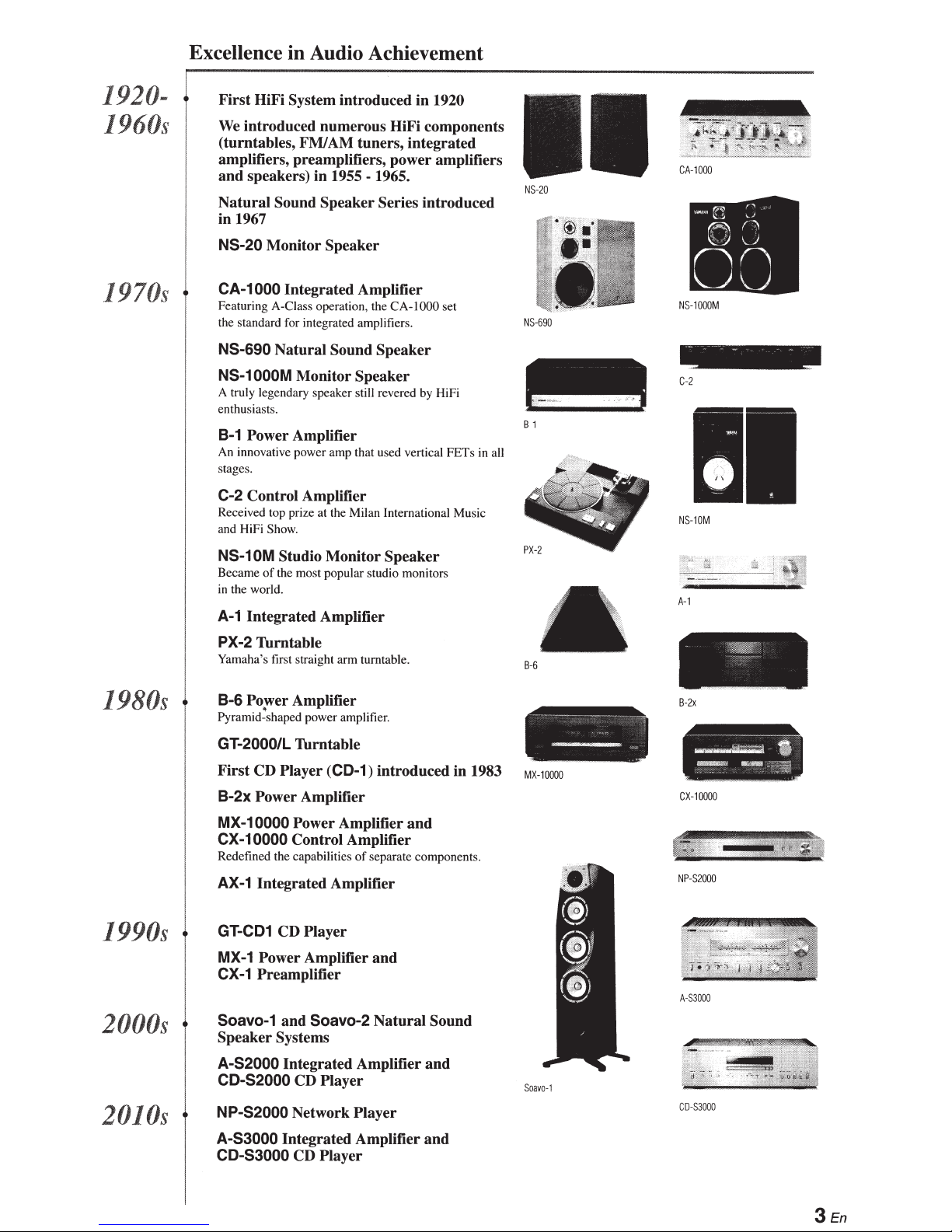
Excellence
in
Audio Achievement
1920-
1960s
1970s
First HiFi System introduced in
We
introduced numerous HiFi components
1920
(turntables, FMJAM tuners, integrated
amplifiers, preamplifiers, power amplifiers
and speakers) in
Natural
in
NS-20
CA-1
F
ea
the standard for integrated amplifiers.
NS-690
NS-1
A truly legendary speaker still rev
enthusiasts.
Sound
1967
Monitor Speaker
000
turing A-Class operation, the CA-1000 set
Natural
OOOM
1955- 1965.
Speaker Series introduced
Integrated Amplifier
Sound
Speaker
Monitor Speaker
ere
d by HiFi
8-1 Power Amplifier
An
innovative pow
stag
es
.
C-2
Control Amplifier
Received top prize at the Milan Interna
and HiFi Sho
er
amp that used vertical FETs in all
w.
ti
onal Music
NS-
NS-
B-1
20
690
CA
NS-1
C-2
NS
-
1000
000
-1
0M
M
1980s
1990s
2000s
NS-10M
Became
in
the world.
A-1
PX-2
Ya
mah
8-6
P
y
r
GT-2000/L
Studio Monitor Speaker
of
the most popular studio monitors
Integrated Amplifier
Thrntable
a's
first straight arm turntable.
Power Amplifier
a
mid~sh
a
p
e
d
power amplifier.
Thrntable
First CD Player
8-2x
Power Amplifier
MX-10000
CX-10000
Redefined the
AX-1
GT
-
CD1
MX-1
CX-1
Soavo-1
Power Amplifier
Control Amplifier
ca
pabilities of separate
Integrated Amplifier
CD Player
Power Amplifier and
Preamplifier
and
Soavo-2
Speaker Systems
(CD-1)
introduced in
and
co
mponents.
Natural
Sound
1983
B-6
MX-1
0000
A-
1
B-
2x
-
- -
cx
-1
oo
NP-S
2
A-
S3
000
oo
000
-
-~-
~
--
•
--
::::
1!
A-S2000
CD-S2000
2010s
NP-S2000
A-S3000
CD-S3000
Integrated Amplifier and
CD Player
Network Player
Integrated Amplifier
CD Play
er
and
S
oa
v
o-1
C
D-
53
000
3En
A-52100
Full floating
+
balanced circuit design achieves the
and
potential
full
of
analogue amplification
entirely new floating and balanced power amplifier achieves complete symmetry and permits full balanced
An
to just before the speaker jack.
transmission (amplification) from the input
Full-stage balanced signal transmission
+
The integrated amplifier offers full stage balanced transmission, combining high power output with good sound texture
performance.
and outstanding
Parallel volume
+
Large power supply with
+
Left-right symmetrical design with rigid, stable construction
+
Discrete phono
+
High-quality headphone amplifier
+
• Supplied
Please check that you have received all
Remote control
•
Batteries
•
• Power
SAFETY BROCHURE
•
SIN
accessories
(AAA,
cable
R03,
and
amplifier
UM-4) (x
2)
jack
tone control
four
the following parts.
of
separate circuits
with low-impedance drive
Contents
functions .......................................•......................................................•........................................... 6
Controls
Connections .......................................................................................................................................................... 16
Specifications ...........................................•........................................................................................••................. 24
Troubleshooting ........................................................................•.......................................................................... 28
About
•
indicates a tip for your operation.
o<il<
•
Photographs and illustrations are for explanatory purposes, and may differ from the actual unit.
•
• Read the
4En
and
manual
this
"SAFETY BROCHURE" before using this unit.

In
chapter, you
this
Controls and
functions
A-52100.
will
learn
the
controls
and
functions
of
• Front panel (pages 6
@YAMAHA
to
9)
STANDBY/ON
OFF
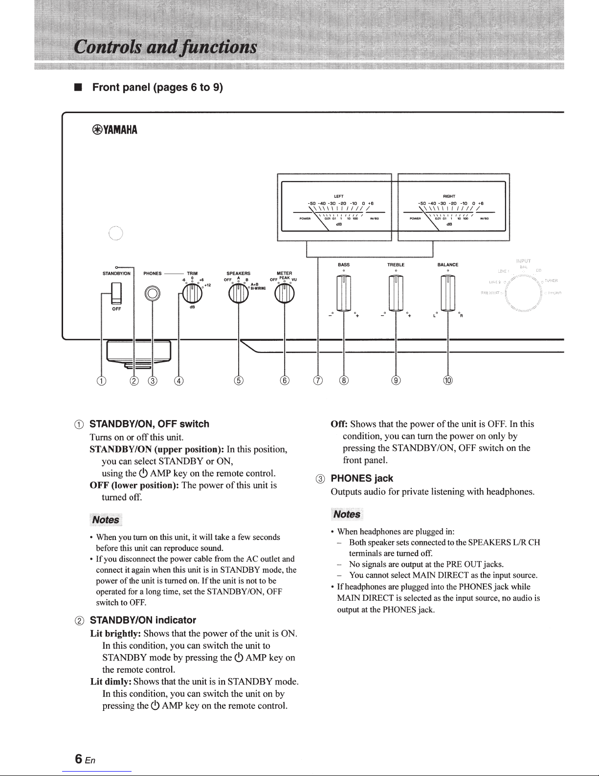
CD
STANDBY/ON, OFF
Turns on or
off
STANDBY/ON
you
can select STANDBY or ON,
using the
OFF
<.9
(Jower position): The power
turned off.
PHONES
--
TRIM SPEAKERS
(g
dB
OFF A B OFF
0 ° 0
...
cBI·WIRUtG
""==
4
switch
this unit.
(upper
position): In this position,
AMP key on the remote control.
5
of
this unit is
METER
oPEfK o VU
6
LEFT
-50 -40
-30 -20
\\\1\11/
7
-10 0 +6
//
//
dB
BASS
0
_o
_o
+
8
Off: Shows that the power
TREBLE
0+
9
-50 -40 -30
\\\\\111111/
BALANCE
L
' '
of
RIGHT
-20
-10 0 •6
dB
R
10
the unit is OFF.
condition, you can turn the power on only
pressing the STANDBY /ON, OFF switch
front panel.
@ PHONES
jack
Outputs audio for private listening with headphones.
In
by
on
this
the
::r2f!$
~
• When you turn on this unit, it will take a few seconds
before this unit can reproduce sound.
If
you
•
disconnect the power cable from the
it
connect
power
again when this unit is
of
the unit is turned on.
operated for a long time, set the STANDBY/ON, OFF
switch to OFF.
® STANDBY/ON
Lit
brightly:
In
this condition, you can switch the unit to
indicator
Shows that the power
STANDBY mode by pressing the
the remote control.
Lit
dimly:
Shows that the unit is in STANDBY mode.
In this condition, you can switch the unit
pressing the
6En
<.9
AMP key on the remote control.
AC
in
STANDBY mode, the
If
the unit is not to be
of
the unit is ON.
<.9
AMP
outlet and
key on
on
by
• When headphones are plugged in:
- Both speaker sets connected to the SPEAKERS L/R CH
terminals are turned off.
- No signals are output at the PRE OUT jacks.
- You cannot select MAIN DIRECT as the input source.
• lfheadphones are plugged into the PHONES
jack
while
MAIN DIRECT is selected as the input source, no audio is
output at the PHONES jack.
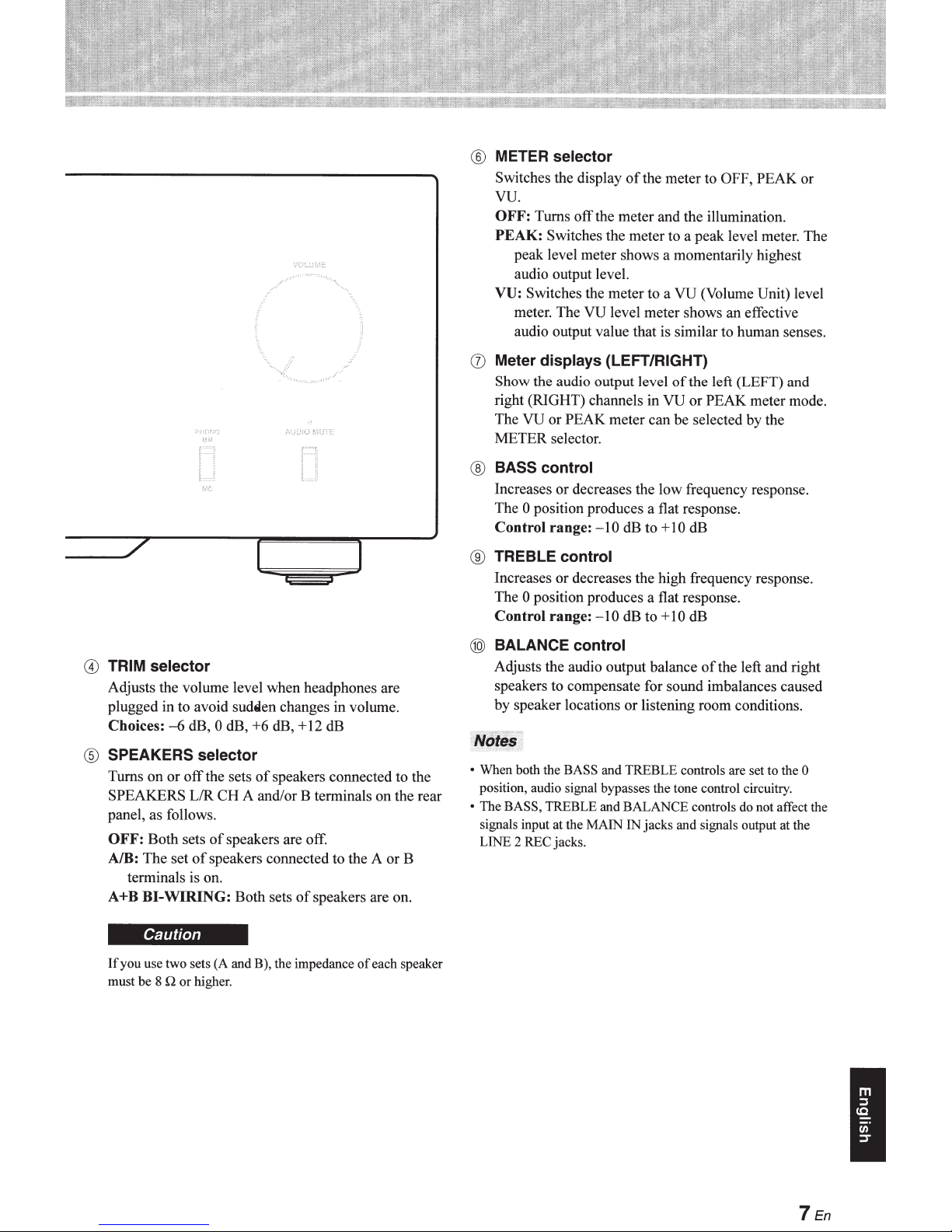
®
METER selector
Switches the display
of
the meter to
OFF, PEAK
vu.
OFF:
Turns
off
the meter and the illumination.
PEAK:
VU:
(]) Meter displays (LEFT/RIGHT)
Show the audio output level
right (RIGHT) channels in
The
METER selector.
®
BASS control
Increases or decreases the low frequency response.
The
Control range:
®
TREBLE control
Increases or decreases the high frequency response.
The
Control range:
Switches the meter to a peak level meter. The
peak level meter shows a momentarily highest
audio output level.
Switches the meter to a
meter. The
audio output value that is similar to human senses.
VU
0 position produces a flat response.
0 position produces a flat response.
or
VU
level meter shows
PEAK
meter can be selected by the
-10
dB to
-10
dB to
VU
(Volume
an
effective
of
the left (LEFT) and
VU
or
PEAK
+
10
dB
+
10
dB
meter mode.
Unit)
or
level
@
TRIM selector
Adjusts the volume level when headphones are
plugged in to avoid sudtilen
Choices:
®
SPEAKERS selector
Turns
SPEAKERS L/R CH A and/
panel, as follows.
OFF:
AlB: The set
A+B BI-WIRING:
If
you use two sets (A and B), the impedance
must
-6
dB,
on
or
off
the sets
Both sets
terminals is on.
Caution
be
8
of
of
speakers connected to the A or B
Q
or
higher.
0
dB,
speakers are off.
changes
+6
dB, +12
of
speakers connected to the
or
Both sets
in
dB
B terminals on the rear
of
speakers are on.
volume.
of
each speaker
@
BALANCE control
Adjusts the audio output balance
speakers to compensate for sound imbalances caused
by speaker locations
•
When both the BASS and TREBLE controls are set to the
position, audio signal bypasses the tone control circuitry.
•
The
BASS, TREBLE and BALANCE controls do not affect the
signals input at the MAIN
LINE 2 REC jacks.
or
listening room conditions.
IN
jacks and signals output at the
of
the left and right
0
7
I
En
• Front panel (pages 6
@YAMAHA
to
9)
~~--------------------------------·1------
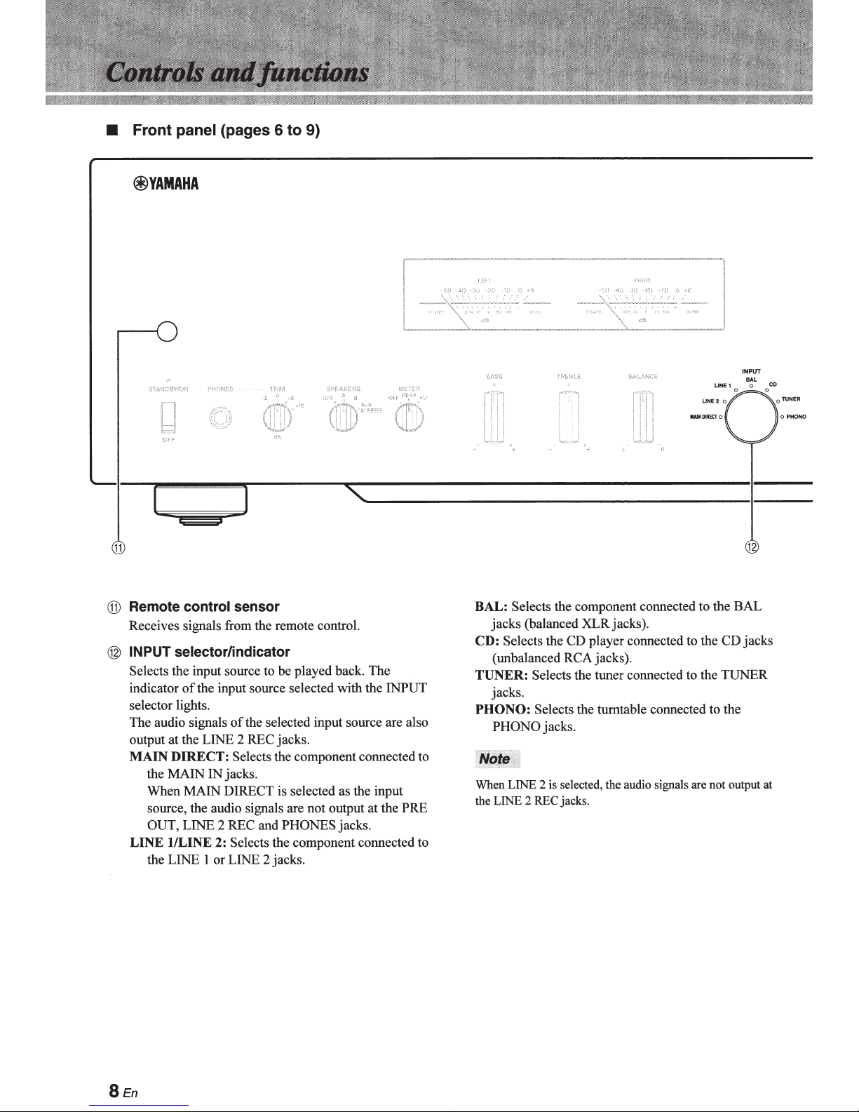
11
@ Remote control sensor
Receives signals from the remote control.
@ INPUT selector/indicator
Selects the input source to be played back. The
of
indicator
selector lights.
The audio signals
output at the LINE 2 REC jacks.
MAIN
the MAIN IN jacks.
When MAIN DIRECT is selected as the input
source, the audio signals are not output at the PRE
OUT, LINE 2 REC and PHONES jacks.
LINE
the LINE 1 or LINE 2 jacks.
the input source selected with the INPUT
of
the selected input source are also
DIRECT:
1/LINE 2: Selects the component connected to
Selects the component connected to
BAL: Selects the component connected to the BAL
jacks (balanced XLRjacks).
CD:
Selects the CD player connected to the
(unbalanced RCA jacks).
TUNER: Selects the tuner connected to the TUNER
jacks.
PHONO:
When LINE 2 is selected, the audio signals are not output at
the LINE 2 REC jacks.
Selects the turntable connected to the
PHONO jacks.
CD
jacks
8En
_
__,7
VOLUME
PHONO AUDIO MUTE
MM
MC
13
14
15
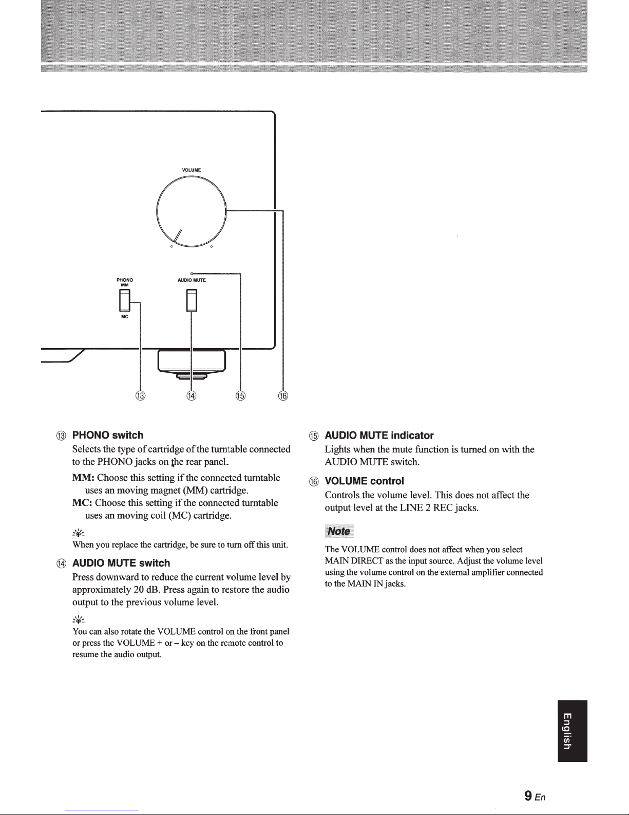
@ PHONO switch
Selects the type
to the
PHONO
MM:
Choose this setting
uses
an
MC: Choose this setting
an
uses
,,,
~<i>-=-
When you replace the cartridge,
of
cartridge
jacks
moving magnet (MM) cartridge.
moving coil (MC) cartridge.
of
the turntable connected
on
the rear paneL
if
the connected turntable
if
the connected turntable
be
sure to rum
off
@ AUDIO MUTE switch
Press downward to reduce the current volume level by
approximately 20 dB. Press again to restore the audio
output
to
the previous volume level.
,,,
~<i>-=-
You
can also rotate the VOLUME control on the front panel
or press the
resume
the
VOLUME+
audio output.
or - key on the remote control
16
this unit.
to
@ AUDIO MUTE indicator
Lights when the mute function is turned
AUDIO MUTE switch.
on
with the
@ VOLUME control
Controls the volume level. This does not affect the
output level at the LINE 2 REC jacks.
The VOLUME control does
MAIN DIRECT as the input source. Adjust the volume level
using the volume control
to
the MAIN IN jacks.
not
affect when you select
on
the external amplifier connected
I
9 En
•
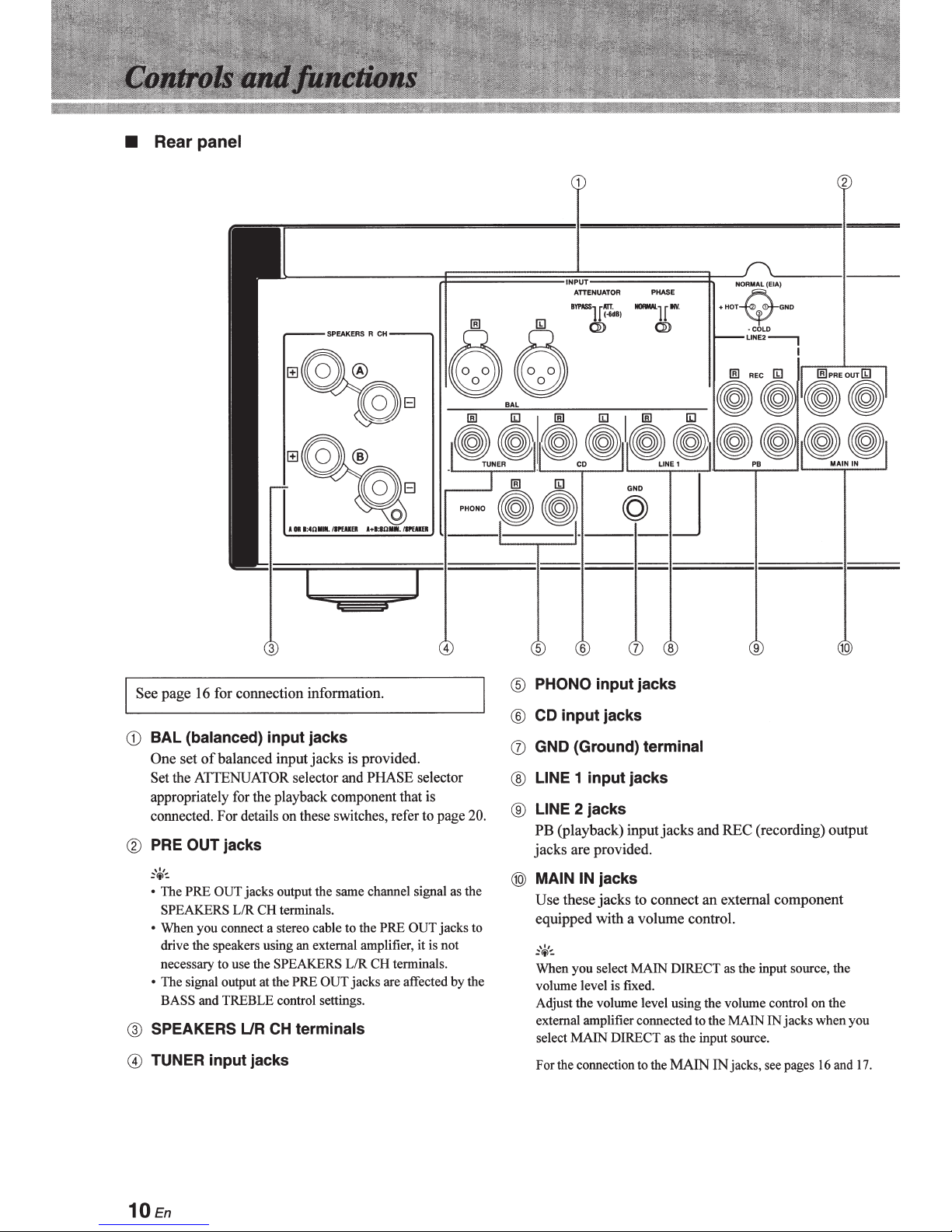
Rear
panel
L--------rt=======~
16 for connection information.
page
See
jacks
L/R
use the
LJR
input jacks
is provided.
jacks
input
selector and PHASE selector
terminals.
CH
PRE
the
to
CH
SPEAKERS
PRE
terminals
CH
L/R
OUT jacks are affected by the
terminals.
(balanced)
BAL
CD
ofbalanced
set
One
ATfENUATOR
Set the
appropriately for the playback component that is
connected. For details on these switches, refer to page
OUT
PRE
®
:-'ci'~
OUT jacks output the same channel signal as the
PRE
• The
SPEAKERS
When you connect a stereo cable
•
drive the speakers using an external amplifier,
necessary
The signal output at the
•
BASS and TREBLE control settings.
SPEAKERS
@
TUNER input jacks
0
to
OUT
is not
it
20.
jacks to
~.U~T======~r~NORMAL(E'"",.-,
..
ATTENUATOR
riiTT·
BYPASS
1·
1
Q} Q}
PHONO input jacks
®
input jacks
CD
®
GND (Ground)
(j)
1 input jacks
LINE
®
2 jacks
LINE
®
PB (playback) input
are provided.
jacks
MAIN IN
@)
Use
equipped with a volume control.
~'4'-:
When
volume level is fixed.
Adjust the volume level using the volume control
external amplifier connected
select
For the connection to the
jacks
jacks
these
select MAIN DIRECT as the input source, the
you
MAIN
PHASE
riNV.
-
6dB)
1
terminal
jacks
to connect
DIRECT as the input source.
MAIN
w
+HOT
·COLD
LINE2-,
and REC (recording) output
external component
an
the MAIN IN
to
cks, see pages 16 and
ja
IN
, GND
jack
----I----
I
on
s when you
the
.
17
10En
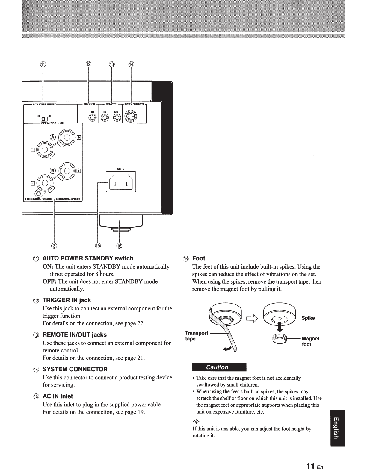
® AUTO POWER STANDBY switch
ON:
The unit enters STANDBY mode automatically
if
not operated for 8 hours.
OFF:
The
unit does not enter STANDBY mode
automatically.
@ TRIGGER IN jack
Use this
trigger function.
For details on the connection, see page 22.
@ REMOTE IN/OUT jacks
Use these
remote control.
For details
@ SYSTEM CONNECTOR
Use this connector to connect a product testing device
for servicing.
@
AC
Use this inlet to plug
For
jack
jacks
on
IN inlet
details
to connect an external component for the
to connect an external component for
the connection, see page 21.
in
the supplied power cable.
on
the connection, see page 19.
@Foot
The feet
spikes can reduce the effect
When using the spikes, remove the transport tape, then
remove the magnet foot
of
this unit include built-in spikes. Using the
of
vibrations on the set.
by
pulling it.
¢~··;~
Transport
tape
---¥\
~Magnet
Caution
• Take care that the magnet foot is not accidentally
swallowed by small children.
• When using the feet's built-in spikes, the spikes may
on
scratch the shelf or floor
the magnet feet or appropriate supports when placing this
on
expensive furniture, etc.
unit
,,,
:<t>~
If
this unit is unstable, you can adjust the foot height by
rotating it.
which this unit is installed. Use
foot
I
11
En
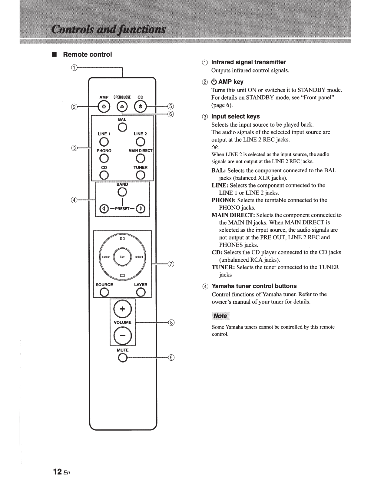
• Remote
control
Infrared
CD
Outputs
signal
infrared control signals.
transmitter
OPEN/CLOSE
AMP
LINE
1
0
BAL
0
®---f--0
0 0
PHONO
0 0
CD
0 0
BAND
4)---+---1
0-PRESET-0
SOURCE
0
I
~
DD
D
-=====
0 0
CD
0+~
2
LINE
DIRECT
MAIN
TUNER
LAYER
(!)AMP
®
Turns this unit ON or switches it to
For details
(page 6).
Input
@
Selects
The audio signals
output at the LINE 2 REC jacks.
,,,
:<i>~
When LINE 2 is selected as the input source, the audio
signals are not output at the LINE 2 REC jacks.
BAL:
LINE:
PHONO:
MAIN
CD: Selects the CD player connected to the CD jacks
TUNER:
Yamaha
G)
Control functions
owner's manual
key
STANDBY
STANDBY
on
select
Selects
jacks (balanced XLRjacks).
LINE
PHONO jacks.
the MAIN
selected as the input source, the audio signals are
not output at the PRE
PHONES
(unbalanced RCA jacks).
jacks
keys
the input source to be played back.
of
the component connected to the BAL
Selects
DIRECT:
the component connected to the
or LINE 2 jacks.
I
Selects
Selects the tuner connected to the TUNER
tuner
the turntable connected to the
Selects
jacks. When MAIN DIRECT is
IN
jacks.
control
of
of
mode, see
the selected input source are
the component connected to
OUT, LINE 2 REC and
buttons
Yamaha tuner. Refer to the
your tuner for details.
"Front panel"
mode.
8
VOLUME
8
MUTE
O
12En
1---:---<8
--;-----®
r--
Yamaha tuners cannot
Some
control.
controlled by this remote
be
@<!)CD
key
Turns the Yamaha
STANDBY
mode.
CD
player
or switches it to
ON
keys
VOLUME
@
Control the volume level.
+1-
OPEN/CLOSE
~
@
Opens/closes the disc tray
Refer to
details.
Some Yamaha
or~
Yamaha CD player control keys
(j)
Control various functions
to the owner's manual
t>
1111
D
I<J<J
SOURCE:
LAYER:
the owner's manual
CD
OPEN/CLOSE
(Play):
(Pause):
resume playback.
(Stop):
back to the beginning
Yamaha
each time this key is pressed.
CD between SA-CD and
Starts playback.
Pauses playback. Press the
Stops
(Skip):
t>t>1
I
Selects the source to be played on the
CD player. The playback source changes
Switches the playback layer
key
of
players do not support the
this remote control.
of
key
of
your CD player for details.
of
playback.
Skips to the next track,
of
the Yamaha
your CD player for
of
Yamaha
the current track.
.
CD
CD player.
CD
<!)
CD player. Refer
1:>
or
a hybrid
of
key and/
II II
or
skips
to
SA-
VOLUME
The
DIRECT as the input source. Adjust the volume level on the
external amplifier connected to the MAIN IN jacks.
® MUTE
Reduces the current volume level by approximately
dB. Press again
20
previous volume level. Pressing the
key also cancels muting.
keys do not affect when you select MAIN
key
restore the audio output to the
to
VOLUME+
or-
..
I
13En
 Loading...