

Page 1

Owner's Manual
Page 2
SPECIAL MESSAGE SECTION
PRODUCT SAFETY MARKINGS: Yamaha electronic
products may have either labels similar to the graphics
shown below or molded/stamped facsimiles of these
graphics on the enclosure. The explanation of these graphics appears on this page. Please observe all cautions indicated on this page and those indicated in the safety instruction section.
CAUTION
RISK OF ELECTRIC SHOCK
DO NOT OPEN
CAUTION: TO REDUCE THE RISK OF ELECTRIC SHOCK.
DO NOT REMOVE COVER (OR BACK).
NO USER-SERVICEABLE PARTS INSIDE.
REFER SERVICING TO QUALIFIED SERVICE PERSONNEL.
The exclamation point within the equilateral triangle is intended to alert the
user to the presence of important operating and maintenance (servicing) instructions in the literature accompanying the product.
ENVIRONMENTAL ISSUES: Yamaha strives to produce products that are both user safe and environmentally
friendly. We sincerely believe that our products and the
production methods used to produce them, meet these
goals. In keeping with both the letter and the spirit of the
law, we want you to be aware of the following:
Battery Notice: This product MAY contain a small nonrechargable battery which (if applicable) is soldered in
place. The average life span of this type of battery is approximately five years. When replacement becomes necessary, contact a qualified service representative to perform the replacement.
Warning: Do not attempt to recharge, disassemble, or
incinerate this type of battery. Keep all batteries away
from children. Dispose of used batteries promptly and as
regulated by applicable laws. Note: In some areas, the
servicer is required by law to return the defective parts.
However, you do have the option of having the servicer
dispose of these parts for you.
Disposal Notice: Should this product become damaged
beyond repair, or for some reason its useful life is considered to be at an end, please observe all local, state, and
federal regulations that relate to the disposal of products
that contain lead, batteries, plastics, etc.
The lightning flash with arrowhead
symbol, within the equilateral triangle,
is intended to alert the user to the presence of uninsulated “dangerous voltage” within the product’s enclosure that
may be of sufficient magnitude to constitute a risk of electrical shock.
IMPORTANT NOTICE: All Yamaha electronic products are tested and approved by an independent safety
testing laboratory in order that you may be sure that when
it is properly installed and used in its normal and customary manner, all foreseeable risks have been eliminated.
DO NOT modify this unit or commission others to do so
unless specifically authorized by Yamaha. Product performance and/or safety standards may be diminished.
Claims filed under the expressed warranty may be denied
if the unit is/has been modified. Implied warranties may
also be affected.
SPECIFICATIONS SUBJECT TO CHANGE: The
information contained in this manual is believed to be
correct at the time of printing. However, Yamaha reserves
the right to change or modify any of the specifications
without notice or obligation to update existing units.
92-469- ➀
NOTICE: Service charges incurred due to lack of knowledge relating to how a function or effect works (when the
unit is operating as designed) are not covered by the
manufacturer’s warranty, and are therefore the owners
responsibility. Please study this manual carefully and consult your dealer before requesting service.
NAME PLATE LOCATION: The graphic below indicates the location of the name plate. The model number,
serial number, power requirements, etc., are located on
this plate. You should record the model number, serial
number, and the date of purchase in the spaces provided
below and retain this manual as a permanent record of
your purchase.
Rear Panel
Model _____________________________________
Serial No. __________________________________
Purchase Date ______________________________
Page 3
PRECAUTIONS
PLEASE READ CAREFULLY BEFORE PROCEEDING
* Please keep these precautions in a safe place for future reference.
WARNING
Always follow the basic precautions listed below to avoid the possibility of serious injury or even death from electrical shock,
short-circuiting, damages, fire or other hazards. These precautions include, but are not limited to, the following:
• This instrument contains no user-serviceable parts. Do not attempt to disassemble or modify the internal components in any way.
• Do not expose the instrument to rain, use it near water or in damp or wet
conditions, or place containers on it containing liquids which might spill
into any openings.
• If the power cord or plug becomes frayed or damaged, or if there is a sudden
loss of sound during use of the instrument, or if any unusual smells or
smoke should appear to be caused by it, immediately turn off the power
switch, disconnect the electric plug from the outlet, and have the instrument
inspected by qualified Yamaha service personnel.
CAUTION
Always follow the basic precautions listed below to avoid the possibility of physical injury to you or others, or damage to the
instrument or other property. These precautions include, but are not limited to, the following:
• Do not place the power cord near heat sources such as heaters or radiators,
and do not excessively bend or otherwise damage the cord, place heavy
objects on it, or place it in a position where anyone could walk on, trip over,
or roll anything over it.
• When removing the electric plug from an outlet, always hold the plug itself
and not the cord. Pulling by the cord can damage it.
• Do not connect the instrument to an electrical outlet using a multiple-connector. Doing so can result in lower sound quality, or possibly cause overheating in the outlet.
• Remove the electric plug from the outlet when the instrument is not to be
used for extended periods of time, or during electrical storms.
• Before connecting the instrument to other electronic components, turn off
the power for all components. Before turning the power on or off for all
components, set all volume levels to minimum.
• Do not expose the instrument to excessive dust or vibrations, or extreme cold or
heat (such as in direct sunlight, near a heater, or in a car during the day) to prevent
the possibility of panel disfiguration or damage to the internal components.
• Do not use the instrument near other electrical products such as televisions,
radios, or speakers, since this might cause interference which can affect
proper operation of the other products.
• Do not place the instrument in an unstable position where it might accidentally fall over.
• Only use the voltage specified as correct for the instrument. The required
voltage is printed on the name plate of the instrument.
• Always connect the three-pin attachment plug to a properly grounded power
source. (For more information about the main power supply, see “Connecting the Power.)
• Before cleaning the instrument, always remove the electric plug from the
outlet. Never insert or remove an electric plug with wet hands.
• Check the electric plug periodically and remove any dirt or dust which may
have accumulated on it.
• Before moving the instrument, remove all connected cables.
• When cleaning the instrument, use a soft, dry cloth. Do not use paint thinners,
solvents, cleaning fluids, or chemical-impregnated wiping cloths. Also, do not
place vinyl or plastic objects on the instrument, since this might discolor the panel.
• Do not rest your weight on, or place heavy objects on the instrument, and do
not use excessive force on the buttons, switches or connectors.
• Do not place objects in front of the instrument's air vent, since this may
prevent adequate ventilation of the internal components, and possibly result
in the instrument overheating. To ensure adequate ventilation and cooling,
leave at least 10cm of open space behind the A3000 rear panel, and at least
4cm of open space above the top cover.
• Do not operate the instrument for a long period of time at a high or uncomfortable volume level, since this can cause permanent hearing loss. If you
experience any hearing loss or ringing in the ears, consult a physician.
■SAVING USER DATA
• To protect against data loss caused by malfunction or operating error, be sure
to save your data regularly to floppy disk, hard disk or other storage medium.
Yamaha cannot be held responsible for damage caused by improper use or modifications to the instrument, or data that is lost or destroyed.
Always turn the power off when the instrument is not in use.
■Handling and Installation of Options
WARNING
• Before beginning installation, switch off the power to the A3000 and
connected peripherals, and unplug them from the power outlet. Then
remove all cables connecting the A3000 to other devices. (Leaving the
power cord connected while working can result in electric shock. Leaving other cables connected can interfere with work.)
• Do not disassemble, modify, or apply excessive force to board areas and
connectors on option boards, hard disk, and SIMMs. Bending or tampering with boards and connectors may lead to electric shock, fire, or
equipment failures.
* Consult your Yamaha dealer if you have any questions regarding installation procedures for options boards, hard disks, SIMMs, or other optional devices.
* If SIMM memory, hard disk, or other optional component fails to work properly, consult the item's dealer for advice.
CAUTION
• Before handling an option board, hard disk, or SIMM, you should briefly touch
the A3000 metal casing (or other such metallic area) with your bare hand so as
to drain off any static charge from your body. Note that even a slight amount of
electrostatic discharge may cause damage to these components.
• It is recommended that you wear gloves to protect your hands from metallic
projections on the A3000, hard disk, SIMMs, option boards, and other components. Touching leads or connectors with bare hands may cause finger
cuts, and may also result in poor electrical contact or electrostatic damage.
• Take care to avoid dropping screws into the A3000 unit. If a screw does
fall in, be sure to remove it before you reassemble and power up the unit.
Starting the unit with a loose screw inside may lead to improper operation or equipment failure. (If you are unable to retrieve a dropped screw,
consult your Yamaha dealer for advice.)
Page 4

Features
Features
Versatile Professional Sampler
The A3000 professional sampler is an ideal break-beat
machine and phrase sampler for a wide variety of recording and performance applications.
Excellent Effects System
The A3000’s triple-block effect system lets you set up
as many as three independent effects. Select from a wide
range of built-in effects — including original effects
custom-designed to heighten the performance qualities of phrase and break-beat play. You can also apply
effects to incoming signals as you record them, and to
analog input that you feed through the A3000 for
realtime output.
List of Accessories
Easy to Use
The A3000 presents its editing and control capabilities
in an easy-to-use three-level arrangement. All operations are handled using front-panel mode buttons, function keys, and knobs. You can access and edit any setting by selecting the mode, then selecting the function, and then turning the knobs directly under the
screen. It is also possible to use knobs and function
keys to control realtime playback.
Performance-Enhancing Options
Installation of the optional I/O expansion board (AIEB1
board) adds digital I/O capability plus six additional assignable-output pairs to your A3000. The A3000 also
accepts up to 128MB of expansion memory.
Your A3000 package includes the following accessories. Make sure that all of these accessories are included.
• CD-ROM
• Power cord
• MIDI cable
• Five floppy disks
• Owner’s Manual
• Power supply cable for hard disk (red/white 4-wire cable)
• SCSI cable for hard disk
* If any of the above items is missing, please contact your Yamaha dealer for assistance.
Unauthorized copying of copyrighted software for purposes other than purchaser’s personal use is prohibited.
2
Page 5

PROFESSIONAL SAMPLER
Features
Owner’s Manual
Thank you for your purchase of the Yamaha A3000 Professional Sampler. The A3000
incorporates a leading-edge AWM2 tone generator, and is an ideal for use with synthesizers, MIDI keyboards, and other MIDI devices in a wide variety of musical applications.
This owner’s manual will help you get the most from your A3000’s many advanced features. Please read through the essential parts of the manual carefully before beginning
work with your sampler, and refer back to the manual for additional information as
necessary. Please be sure to store the manual in a safe and handy location.
3
Page 6

Contents
Contents
Using the Manual .............................................................................. 6
Panel and Connector Arrangement .................................................. 8
A3000 Options ................................................................................. 14
Handling the Floppy Disk Drive(FDD) and Floppy Disk ............... 16
Chapter 1 Setting Up
Setting Up........................................................................................ 20
Connecting the Power .................................................................... 21
Connecting the A3000 Outputs ...................................................... 22
Connecting the Audio Inputs ......................................................... 25
MIDI Connections ........................................................................... 27
Power ON/OFF ................................................................................ 30
Sound Check ................................................................................... 32
Chapter 2 Trying It Out
Introduction .................................................................................... 36
Starting Out .................................................................................... 38
Next Step ......................................................................................... 45
Sample Editing................................................................................ 52
Program Editing ............................................................................. 57
Sequence Play ................................................................................. 62
Saving and Reloading Your Data .................................................... 64
Accompanying Disks ....................................................................... 68
Chapter 3 Basics
Samples and Programs ................................................................... 70
Sample Output Destinations and Effects ....................................... 78
Data Configuration and Handling .................................................. 80
Modes and Functions ...................................................................... 84
Basic Operation ............................................................................... 86
Other Keys and Operations ............................................................. 91
Chapter 4 PLAY Mode
Play Mode ........................................................................................ 94
Program & Sample Selection Screen ............................................. 95
PROGRAM/SAMPLE Selection Screen ................................................... 95
COMMAND Pages ............................................................................ 98
SAVE ........................................................................................................ 98
INIT (Program Initialization) ............................................................... 101
COPY ..................................................................................................... 102
PGMDUMP (Program Dump) .............................................................. 103
SETINIT (Set Program’s Initial Conditions)........................................ 104
NEWBANK (Create a Sample Bank) ..................................................... 105
DELETE ................................................................................................ 106
DUPL (Duplicate) .................................................................................. 107
SMPDUMP (Sample Dump) .................................................................. 108
PROGRAM Function ..................................................................... 110
PROGRAM - PgmSel (Select Program) ................................................ 110
SAMPLE Function ........................................................................ 112
SAMPLE - SmpSel (Select Sample)...................................................... 112
SAMPLE - SmpBnk (Select Sample from Sample Bank) .................... 114
SAMPLE - ToBank (Assign Sample to Bank) ....................................... 115
SAMPLE - SmpSort (Sort Samples) ..................................................... 117
EASY EDIT Function .................................................................... 118
EASY EDIT - EasyEd ............................................................................. 119
EFFECT Function ......................................................................... 121
EFFECT - EfType (Select the Effect Types) .......................................... 121
EFFECT - Efct1,...,Efct3 (Edit the Effects) .......................................... 124
EFFECT - In&Out (Input/output levels and pan) ................................ 126
EFFECT - EdType (Effect Edit Type) .................................................... 127
SETUP Function ........................................................................... 128
SETUP - PgmMstr (Program’s Master Settings) .................................. 128
SETUP - Portmnt (Portamento) ........................................................... 130
SETUP - ADSetup (A/D-In Setup) ........................................................ 132
SETUP - ADOut (Output Setup for A/D-Input Signal) ........................ 134
CONTROL Function...................................................................... 136
CONTROL - PgmCtl1 (Program Controller Setup 1) .......................... 136
CONTROL - PgmCtl2 (Program Controller Setup 2) .......................... 139
CONTROL - Reset (Controller Reset) ................................................... 141
Chapter 5 EDIT Mode
EDIT Mode .................................................................................... 144
COMMAND Pages .......................................................................... 147
SAVE ...................................................................................................... 147
REVERT ................................................................................................. 149
NORM (Normalize) ............................................................................... 150
RESMPL - TmStrch (Resampling - Time Stretch) .............................. 151
RESMPL - PtchCnv (Resampling - Pitch Conversion) ........................ 153
FADE ..................................................................................................... 155
REVERS (Reverse) ................................................................................ 157
LOOPXFD (Loop Crossfade) ................................................................. 158
SETINIT (Register Initial Parameter Values)....................................... 160
TRIM/LOOP Function ................................................................... 161
TRIM/LOOP - Config (Configure)......................................................... 161
TRIM/LOOP - Wave (Edit Waveform) ................................................... 164
TRIM/LOOP - Loop (Edit Loop Addresses)........................................... 166
TRIM/LOOP - WvMode (Set Wave Mode) ............................................. 168
MAP/OUT Function ....................................................................... 170
MAP/OUT - KeyRnge (Key Range) ........................................................ 170
MAP/OUT - VelRnge (Velocity Range) .................................................. 172
MAP/OUT - Lvl&Mode ........................................................................... 174
MAP/OUT - Output ................................................................................ 176
MAP/OUT - Pitch ................................................................................... 178
MAP/OUT - Expand ............................................................................... 179
MAP/OUT - LvlScale (Level Scaling) .................................................... 180
FILTER Function .......................................................................... 182
FILTER - Filter ...................................................................................... 182
FILTER - FltSens (Filter Sensitivity) ................................................... 184
FILTER - FltScale (Filter Scaling) ........................................................ 185
FILTER - EQ (Equalization) ................................................................. 187
EG Function .................................................................................. 188
EG - AEG (Amplitude Envelope Generator)......................................... 188
EG - AEGMode (AEG Mode Settings) ................................................... 190
EG - FEGRate (Filter-EG Rates) ........................................................... 192
EG - FEGLevel (Filter-EG Levels) ........................................................ 194
EG - FEGMode (FEG Mode Settings) ................................................... 196
EG - PEGRate (Pitch-EG Rates) ........................................................... 198
EG - PEGLevel (Pitch-EG Levels) ........................................................ 200
4
Page 7

Contents
EG - PEGMode (PEG Mode Settings) ................................................... 201
LFO Function ................................................................................ 203
LFO - Common ..................................................................................... 203
LFO - FltrMod (Filter Modulation) ...................................................... 205
LFO - PtchMod (Pitch Modulation)...................................................... 206
LFO - AmpMod (Amplitude Modulation) ............................................. 207
MIDI/CTRL Function .................................................................... 208
MIDI/CTRL - RCh&Alt (Receive Channel and Alternate ..................... 208
MIDI/CTRL - SmpCtl1 (Sample Controller Setup 1) ........................... 210
MIDI/CTRL - SmpCtl2 (Sample Controller Setup 2) ........................... 213
MIDI/CTRL - Vel&PB (Velocity and Pitchbend)................................... 215
Chapter 6 RECORDING Mode
RECORDING Mode ....................................................................... 220
COMMAND Page ........................................................................... 221
SAVE ...................................................................................................... 221
RECORD Function ........................................................................ 223
RECORD - Record ................................................................................. 223
SETUP Function ........................................................................... 227
SETUP - RecData .................................................................................. 227
SETUP - Target ...................................................................................... 230
SETUP - KeyRnge ................................................................................. 232
SETUP - Trigger .................................................................................... 234
SETUP - Process.................................................................................... 235
METER Function .......................................................................... 236
METER - Meter ..................................................................................... 236
METER - TrgLvl .................................................................................... 237
EFFECT Function ......................................................................... 238
EFFECT - EfType (Select the Effect Types) ........................................ 238
EFFECT - RecEf1,...,RecEf3 (Edit the Effects) .................................... 239
EFFECT - In&Out (Input/output levels and pan) ................................ 240
EFFECT - EdType (Effect Edit Type) .................................................... 240
EXT CTRL Function ..................................................................... 241
EXT CTRL - CD-ROM ........................................................................... 241
EXT CTRL - CD-DA ............................................................................... 242
MONITOR Function ...................................................................... 243
MONITOR - Monitor ............................................................................. 243
MONITOR - Click .................................................................................. 245
Chapter 7 DISK Mode
DISK Mode .................................................................................... 248
COMMAND Pages .......................................................................... 249
LOAD ..................................................................................................... 249
DELETE ................................................................................................ 250
COPY ..................................................................................................... 251
FORMAT ................................................................................................ 252
PHYS_FMT (Physical Format) ............................................................. 254
PART_FMT (Format a Partition) .......................................................... 256
FD_FMT (Format a Floppy Disk) ......................................................... 258
PROGRAM Function ..................................................................... 259
PROGRAM - PgmLoad (Load Program(s)) ........................................... 259
SAMPLE Function ........................................................................ 261
SAMPLE - SmpLoad (Load Sample(s)) ................................................ 261
SEQUENCE Function ................................................................... 264
SEQUENCE - SeqLoad (Load Sequence(s)) ......................................... 264
VOLUME Function ........................................................................ 266
VOLUME - Volume ................................................................................ 266
DISK Function .............................................................................. 268
DISK - Disk ........................................................................................... 268
DISK - Config (Configure) .................................................................... 270
DISK - SelfID ........................................................................................ 271
IMPORT Function ......................................................................... 272
IMPORT - ImpSmp (Import a sample) ................................................. 272
IMPORT - ImpVce (Import a voice) ...................................................... 274
IMPORT - ImpOthr (Import Other Data Type) .................................... 276
Chapter 8 UTILITY Mode
UTILITY Mode ............................................................................... 280
COMMAND Pages .......................................................................... 281
SAVE ...................................................................................................... 281
DELETE ................................................................................................ 283
SAVESYS (Save System Settings)......................................................... 284
LOADSYS (Load System Settings) ....................................................... 285
ALLDUMP (Data Dump) ....................................................................... 286
TOTAL EQ Function ..................................................................... 287
Total EQ - Gain...................................................................................... 288
Total EQ - Freq...................................................................................... 289
Total EQ - Width ................................................................................... 290
PANEL PLAY Function .................................................................. 291
PANEL PLAY - KnobCtl (Knob Control) .............................................. 291
PANEL PLAY - KnobSet ........................................................................ 292
PANEL PLAY - FKeySet (Set Function Keys) ....................................... 294
SEQUENCE Function ................................................................... 296
SEQUENCE - SeqSel (Select Sequence) .............................................. 296
SEQUENCE - Play&Rec (Playback and Recording) ............................. 297
MASTER Function ........................................................................ 298
MASTER - Tuning ................................................................................. 298
MASTER - StOut (Stereo Output Assignment) .................................... 299
SYSTEM Function ........................................................................ 300
SYSTEM - Keys ..................................................................................... 300
SYSTEM - Display ................................................................................. 302
SYSTEM - Page ..................................................................................... 303
SYSTEM - FreeMem .............................................................................. 304
MIDI Function .............................................................................. 305
MIDI - Receive ....................................................................................... 305
MIDI - Adjust ......................................................................................... 307
MIDI - RcvFlt (Receiving Filter) ........................................................... 309
MIDI - Bulk (Bulk Dump) ..................................................................... 310
Appendix
Installing SIMMs ........................................................................... 312
Installing the AIEB1 I/O Expansion Board .................................. 316
Setting the SCSI Board Terminator Switch ................................. 320
Installing an Internal Hard Disk .................................................. 323
Connecting external SCSI devices................................................ 328
Specifications ................................................................................ 332
Effect type list ............................................................................... 335
Effect parameter list ..................................................................... 337
Control change number list ......................................................... 347
Troubleshooting ............................................................................ 348
Error messages.............................................................................. 351
MIDI data format........................................................................... 352
Index
Index .............................................................................................. 364
5
Page 8

Using the Manual
Manual Organization
Using the Manual
This manual comprises eight chapters and an Appendix. Chapters 1 and 3 contain essential information and should be read carefully. You may also wish to run through the
brief tutorial given in Chapter 2 before beginning serious work with the A3000.
Chapters 4 through 8 provide detailed information about each of the five operating
modes. Refer to this information as needed while working with the A3000.
■ Chapter 1 Setting Up
This chapter explains the A3000’s controls and connectors, and shows how to connect
up speakers and MIDI devices. Please read through this chapter before you start to work
with the A3000.
■ Chapter 2 Trying It Out
This chapter guides you through a trial run with the A3000. Going through these procedures will help you get a good feel for basic A3000 operations.
■ Chapter 3 Basics
The chapter introduces basic concepts, terminology, and operating procedures. Read
this chapter to learn about samples, sample banks, programs, and sequences; modes
and functions; screen displays; and other important features.
■ Chapter 4 PLAY Mode
This chapter explains all PLAY-mode functions. You use PLAY mode to edit and play
programs.
■ Chapter 5 EDIT Mode
This chapter explains all EDIT-mode functions. You use EDIT mode to edit your samples
and sample banks.
■ Chapter 6 RECORDING Mode
This chapter explains all RECORDING-mode functions. You use RECORDING mode to
record samples and sequences.
■ Chapter 7 DISK Mode
This chapter explains all DISK-mode functions. You use DISK mode to manage your
floppy and hard disks.
■ Chapter 8 UTILITY Mode
This chapter explains all UTILITY-mode functions. You use UTILITY mode to set the
system’s environment.
■ Appendix
Provides option installation instructions, troubleshooting advice, error-message descriptions, A3000 specifications, and MIDI information.
6
Page 9

Finding the Information You Need
You can use any of the following methods to locate information within this manual.
Using the Manual
Icons
Use the
Contents
Check the Contents on pages 4 to 6.
.
Use the Index.
Refer to the Index on pages 363 to 367.
Refer to
Panel and Connector Arrangement
Go to the “Panel and Connector Arrangement” section (pages 8 to 14) and locate the
knob, key, or other component that you require information about. Then refer to the
indicated page.
Leaf through the manual.
Page through sections related to the feature you need information about. Note that
each page has a header indicating the page’s contents, and a footer indicating the chapter name.
This manual uses the following icons to call attention to specific types of information.
Important: An important note or precaution intended to help you avoid
loss of data or other major inconvenience. Always read these notices carefully.
.
FYI (For Your Information): Reference information indirectly related to
the content of the main text. May contain practical advice or general supplementary information.
Procedure: Step-by-step instructions for carrying out a particular operation. A ▼ mark within a procedure indicates the result produced by carrying out the immediately preceding instruction.
☞ xx Page reference. Directs you to another page for related information.
Screen illustrations and other drawings within this manual are for explanatory purposes only, and may in some cases differ from actual displays and configurations.
7
Page 10
Panel and Connector Arrangement
Panel and Connector Arrangement
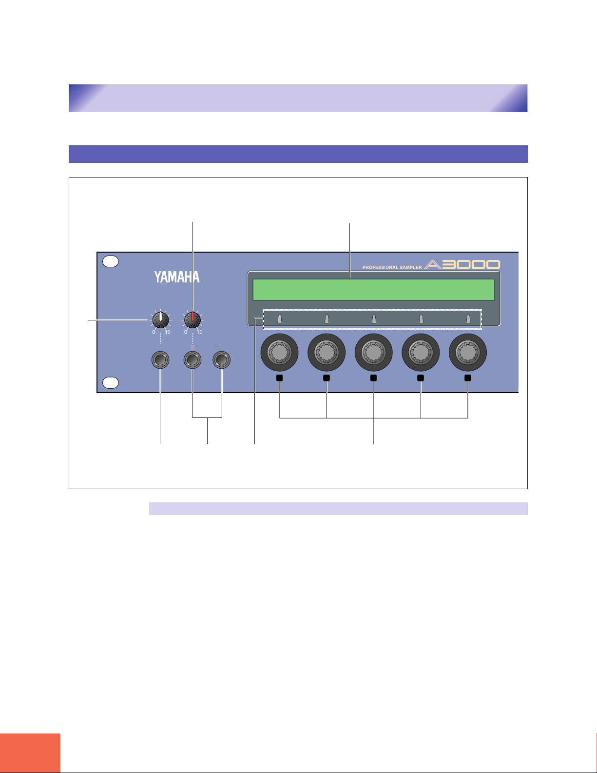
Front Panel (Left Side)
MASTER VOL REC VOL
(5)(2)
(1)
PHONES L INPUT R
1 2 3 4 5
(3)
(1) MASTER VOL (Master Volume)
(4)
Adjusts the output level at the STEREO OUT connectors only. This knob does not affect
the output level at the ASSIGNABLE OUT connectors, or at the various connectors
provided on the optional I/O expansion board (AIEB1 board).
(7)(6)
8
Page 11

(2) REC VOL (Recording Volume)
Adjusts the input level from the front panel’s INPUT L and INPUT R jacks. Use the knob
to adjust the level when recording a sample, or when passing an input signal directly
through the A3000 outputs for realtime output (“A/D In” feature).
This knob does not affect the input level to the DIGITAL IN and OPTICAL IN connectors
on the optional I/O expansion board (AIEB1 board).
(3) PHONES jack
Connects to a set of stereo headphones. The PHONES jack always produces the same
signal as the STEREO OUT jacks. Note that headphone impedance should be between
16 and 150 ohms.
(4) INPUT L, INPUT R jacks
Use these jacks to input an analog signal for recording, or for realtime output (“A/D In”
feature). Use the INPUT L jack if you are supplying a monaural signal.
(5) Display
The display indicates the status and settings for the currently selected function, and
presents messages and confirmation prompts. When you are working at a parametersetting page, the top line of the display indicates the parameter names, while the bottom line shows the current values. The names and values appear directly over the knobs
that you use to make the settings.
Panel and Connector Arrangement
(6) Knob “push” lamps
The lamp above the knob lights up to indicate that the knob can be pushed to execute
some action. If the lamp is off, pushing the knob has no effect.
(7) Knobs
You use the knobs to set the various parameter values, to switch display pages, and
execute operations. In most cases you turn the knob to set a value, and push the knob to
execute an operation — for example, to start or stop recording. Knobs are numbered 1
to 5.
9
Page 12
Panel and Connector Arrangement
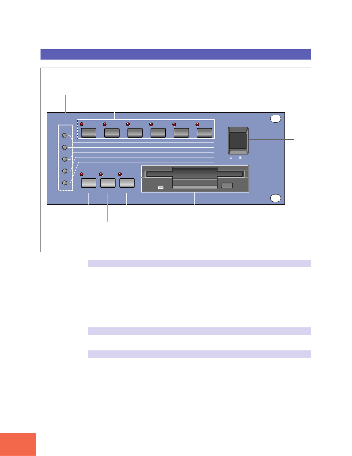
Front Panel (Right Side)
(1)
PLAPLAYY
EDITEDIT
RECREC
DISKDISK
UTILITYUTILITY
(2)
PROGRAMPROGRAM
TRIM/LOOPTRIM/LOOP
RECORDRECORD
PROGRAMPROGRAM
TTOTOTALAL EQ EQ
COMMAND ASSIGNABLE AUDITION
SAMPLESAMPLE
MAP/OUTMAP/OUT
SETUPSETUP
SAMPLESAMPLE
PPANELANEL PLA PLAYY
SEQUENCESEQUENCE
SEQUENCESEQUENCE
EASYEASY EDIT EDIT
FILFILTERTER
METERMETER
EFFECTEFFECT
EGEG
EFFECTEFFECT
VOLUMEVOLUME
MASTERMASTER
SETUPSETUP
LFOLFO
EXITEXIT CTRL CTRL
DISKDISK
SYSTEMSYSTEM
(6)(5)(4)(3)
CONTROLCONTROL
MIDI/CTRLMIDI/CTRL
MONITMONITOROR
IMPORIMPORTT
MIDIMIDI
POWERPOWER
(7)
ON/ON/ OFFOFF
(1) Mode buttons
The A3000 provides five operating modes. You select the mode by pressing the corresponding mode button. The button lamp comes on to indicate that the mode is selected.
Each mode is further divided into six functions. After selecting the mode, you can switch
among its functions by pressing the appropriate function keys.
(The A3000 also uses the button lamps to let you know that it is receiving MIDI data.
Each lamp corresponds to a different MIDI data type, and will continue to blink while
the A3000 is receiving MIDI data of that type. (☞92))
(2) Function keys
Use these keys to switch among the six functions within the currently selected mode.
(3) COMMAND key
You press the COMMAND key to access additional commands relevant to the mode and
function that you are currently working in. (☞91)
10
Page 13

(4) ASSIGNABLE key
You can assign this key any of four different functions. You can set it to operate as a
damp key (so that it switches all sound off), as a controller reset button, or as a toggle
for the knob-controller feature (knobs act as controllers) or the function-key playback
feature (function keys act as MIDI keys). (☞91)
(5) AUDITION key
Press the key to play out the currently selected sample. You use this feature to check the
sound of the sample while editing.
(6) Floppy-disk drive
Accepts a 3.5-inch floppy disk. You can use floppy disks to save and reload your data
(programs, samples, sequences, and system settings).
Note that there is an access lamp at the lower left of the drive. The lamp lights up while
the disk is being accessed. Please do not eject the floppy-disk while this lamp is on.
To eject a disk, press the EJECT button at the lower right of the drive.
(7) POWER switch
Press once to switch the power on. Press again to turn the power off.
Panel and Connector Arrangement
Important
The A3000 stores all new data into main memory only, and will lose all of this data when
you switch off the power. You must therefore be sure to save all important data to disk
before turning the A3000 off.
11
Page 14
Panel and Connector Arrangement
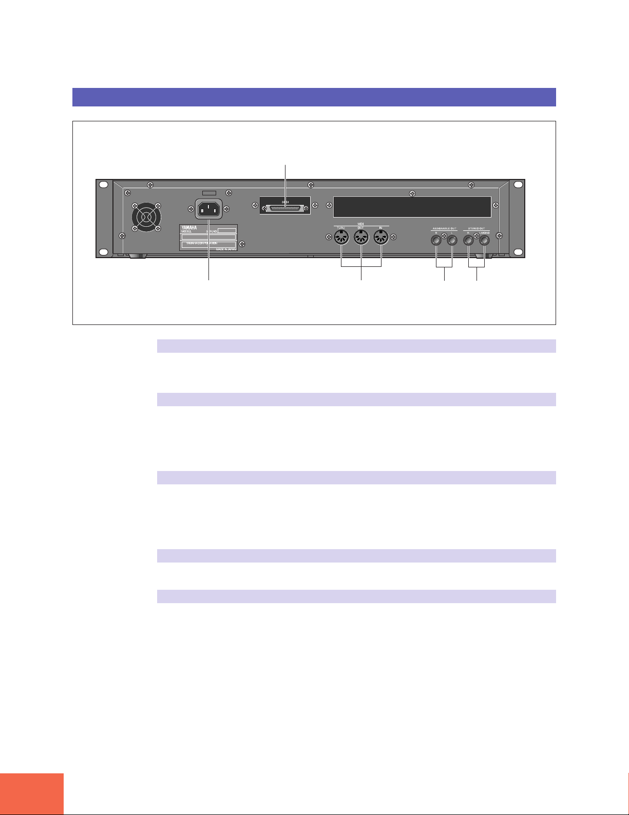
Rear Panel
(5)
(1) (2)
(1) AC inlet
Connects to the AC power cord supplied with the A3000. (Please do not use any other
power cord with this unit.)
(2) MIDI connectors
These connectors link the A3000 to external MIDI devices. The MIDI IN connector receives MIDI signals, while the MIDI OUT connector transmits MIDI data generated by
the A3000. The MIDI THRU connector relays the MIDI signals received at the MIDI IN
connector.
(3) ASSIGNABLE OUT jacks
Analog output jacks. These jacks operate independently of the STEREO OUT jacks. You
can use these jacks to output the sound of one or more selected samples, or to output
the signal supplied through the front panel’s analog input connectors (☞ 134, 176). You
may also set them so that they output the same signal as the STEREO OUT jacks (☞299).
(4) STEREO OUT jacks
These are the main analog output jacks.
(3) (4)
12
(5) SCSI connector
This is a half-pitch 50-pin connector. You use it to connect up a SCSI hard drive, CDROM drive, or other SCSI device.
Page 15
Panel and Connector Arrangement
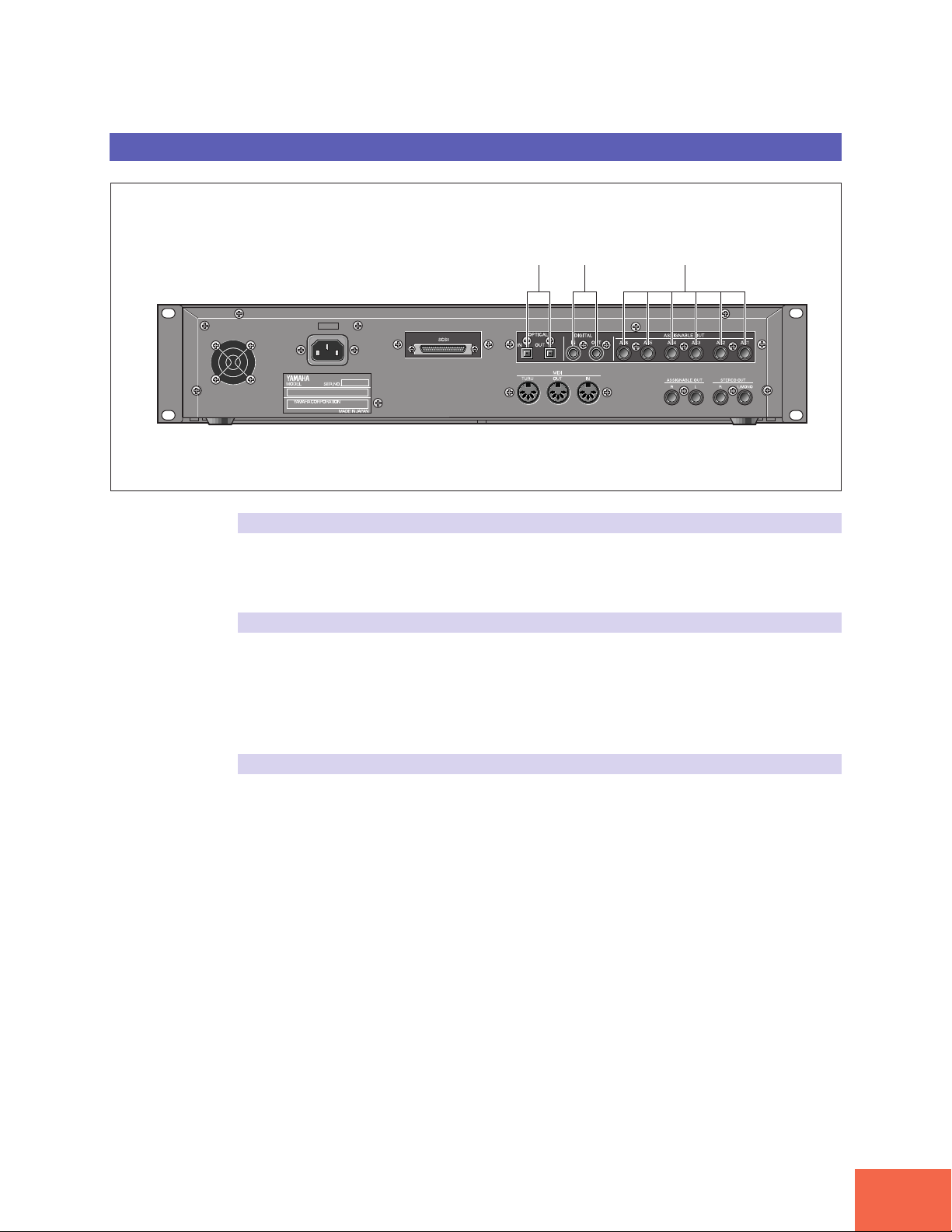
Rear Panel (with optional AIEB1 board installed)
(1) (2) (3)
(1) OPTICAL IN, OUT connectors
Use these connectors to input or output digital signals over optical-fiber cable. You can
use the OPTICAL IN to record a digital signal of frequency 48kHz, 44.1kHz, or 32kHz.
The OPTICAL OUT connector outputs a digital signal of frequency 44.1kHz.
(2) DIGITAL IN, OUT connectors
Use these connectors to input or output digital signals over coaxial (RCA-pin) cable. The
digital signal format is CD/DAT (S/P DIF).
You can use the DIGITAL IN connector to record a digital signal of frequency 48kHz,
44.1kHz, or 32kHz. The DIGITAL OUT connector outputs a digital signal of frequency
44.1kHz.
(3) ASSIGNABLE OUT jacks (AS1 to AS6)
Additional analog output jacks. Each pair (1&2, 3&4, 5&6) operates independently of all
other outputs on the A3000. You can use these jacks to output the sound of one or more
selected samples, or to output the signal supplied through the front panel’s analog input connectors (☞134, 176). You may also set them so that they output the same signal
as the STEREO OUT jacks (☞299).
13
Page 16

A3000 Options
Expansion Memory (SIMMs)
A3000 Options
You can enhance the capability of your A3000 by installing options. The A3000 supports
two options: (1) additional memory, and (2) the AIEB1 board (I/O expansion board).
The A3000 stores all active data in main memory. To play a sample back, you must first
load it into main memory. And whenever you record a sample, you must record it into
main memory.
Samples consume a great deal of memory. The A3000 comes standard with 2 megabytes
(2MB) of memory — but this is only sufficient to store about 23 seconds of high-quality
monaural sound (at 44.1kHz sampling frequency), or approximately 11.5 seconds of
stereo sound.
You can increase this capacity by installing additional memory. The A3000 accepts expansion memory in the form of SIMMs (single in-line memory modules). Using SIMMs,
you can install up to 128MB of memory onto the A3000. SIMMs can be purchased from
almost any computer-supply dealer.
Adding memory will allow you to record longer samples, and to work with more samples at the same time. For information about how to install SIMMs, refer to the Appendix. (☞312)
Important
• You need to use 72-pin SIMMs with access time of 70ns or less. The SIMM module
size may be 4MB, 8MB, 16MB, or 32MB. The A3000 is designed for use with 32-bit
SIMMs, but can also accept installation of 36-bit (parity-type) SIMMs.
• SIMMs must be installed in pairs: you can install either two SIMMs or four SIMMs.
Both modules in a pair must have the same memory capacity.
• The A3000 ships with 2MB of sampling memory installed, and is capable of accessing
up to 128MB. If you add one pair of 32MB SIMMs, for example, you increase the
available sampling memory to a total of (2 + 32×2 =) 66MB. If you install four 32MB
SIMMs, however, the sampling memory size becomes 128MB (and the original 2MB
are effectively disabled).
• For more information about SIMM purchase, refer to your A3000 dealer.
14
Page 17

The I/O Expansion Board (AIEB1 Board)
In its standard configuration, the A3000 supports analog I/O only. Although it stores all
internal data in digital form, it does not provide direct digital I/O connectors.
You can add digital I/O capacity by installing an AIEB1 board. The board offers two
different digital connector types: optical connectors, and coaxial connectors. As an added
benefit, the board also includes three stereo ASSIGNABLE OUTPUT pairs (six analog
jacks), which operate independently of the standard STEREO OUT and ASSIGNABLE
OUT jacks.
For information about how to install this board, refer to the Appendix. (☞312)
A3000 Options
15
Page 18

Handling the Floppy Disk Drive(FDD) and Floppy Disk
Handling the Floppy Disk Drive(FDD) and Floppy Disk
Precautions
Be sure to handle floppy disks and treat the disk drive with care. Follow the important
precautions below.
Disk Type
The A3000 disk drive accepts 2HD-type and 2DD-type 3.5" floppy disks.
Inserting/Ejecting Floppy Disks
To insert a floppy disk into the disk drive:
Hold the disk so that the label of the disk is facing upward and the sliding shutter is
facing forward, towards the disk slot. Carefully insert the disk into the slot, slowly pushing it all the way in until it clicks into place and the eject button pops out.
To eject a floppy disk:
Before ejecting the disk, be sure to confirm that the FDD is stopped (check if the LED
below the floppy disk slot is off).
Press the eject button slowly as far as it will go; the disk will automatically pop out.
When the disk is fully ejected, carefully remove it by hand.
Never attempt to remove the disk or turn the power off during reading or writing. Doing so can damage the disk and possibly the disk drive.
If the eject button is pressed too quickly, or if it is not pressed in as far as it will go, the
disk may not eject properly. The eject button may become stuck in a half-pressed position with the disk extending from the drive slot by only a few millimeters. If this happens, do not attempt to pull out the partially ejected disk, since using force in this
situation can damage the disk drive mechanism or the floppy disk. To remove a partially
ejected disk, try pressing the eject button once again, or push the disk back into the slot
and then repeat the eject procedure.
Be sure to remove the floppy disk from the disk drive before turning off the power. A
floppy disk left in the drive for extended periods can easily pick up dust and dirt that can
cause data read and write errors.
16
Page 19

Handling the Floppy Disk Drive(FDD) and Floppy Disk
Cleaning the Disk Drive Read/Write Head
• Clean the read/write head regularly. This instrument employs a precision magnetic
read/write head which, after an extended period of use, will pick up a layer of magnetic particles from the disks used that will eventually cause read and write errors.
• To maintain the disk drive in optimum working order Yamaha recommends that you
use a commercially-available dry-type head cleaning disk to clean the head about
once a month. Ask your Yamaha dealer about the availability of proper head-cleaning
disks.
Never insert anything but floppy disks into the disk drive. Other objects may cause
damage to the disk drive or floppy disks.
About the Floppy Disks
To handle floppy disks with care:
Do not place heavy objects on a disk or bend or apply pressure to the disk in any way.
Always keep floppy disks in their protective cases when they are not in use.
Do not expose the disk to direct sunlight, extremely high or low temperatures, or excessive humidity, dust or liquids.
Do not open the sliding shutter and touch the exposed surface of the floppy disk inside.
Do not expose the disk to magnetic fields, such as those produced by televisions, speak-
ers, motors, etc., since magnetic fields can partially or completely erase data on the
disk, rendering it unreadable.
Never use a floppy disk with a deformed shutter or housing.
Do not attach anything other than the provided labels to a floppy disk. Also make sure
that labels are attached in the proper location.
To protect your data (Write-protect Tab):
To prevent accidental erasure of important data, slide the disk’s write-protect tab to the
“protect” position (tab open).
Data backup
For maximum data security Yamaha recommends that you keep two copies of important data on separate floppy disks. This gives you a backup if one disk is lost or damaged.
17
Page 20

18
Page 21

1
1
Chapter 1
Setting Up
Page 22

Setting Up
This chapter explains how to set up your equipment and run a simple sound check.
Setting Up
Setup Sequence
This chapter takes you through each of the steps necessary to connect up your system.
Connecting the Power
Explains how to connect up the A3000’s power cord. (☞21)
Connecting the A3000 Outputs
Shows how to connect the A3000’s stereo and assignable outputs to external audio devices. (☞22)
Connecting the Audio Inputs
Shows how to connect microphones and other input devices to the A3000. (☞25)
MIDI Connections
Introduces basic MIDI concepts, and shows how to connect up MIDI devices. (☞27)
Power ON/OFF
Explains the proper sequence for turning connected devices on and off. (☞30)
Sound Check
Takes you through a simple sound check, to confirm that your equipment is connected
correctly. (☞32)
Important
If you have purchased SIMM expansion memory, the AIEB1 expansion board, or an internal hard disk for your A3000, or if you need to connect up an external SCSI disk,
please be sure to install this equipment before going through the procedures given in
this manual. For installation and connection information, please refer to the following
pages.
• SIMM modules ☞312
• AIEB1 board ☞316
• Internal SCSI hard drive ☞326
• External SCSI drive ☞331
20
Chapter 1 Setting Up
Page 23
Connecting the Power
Connecting the Power
This page shows you how to connect up the power cord that comes with the A3000.
Important
• Be sure that the A3000’s power switch is OFF before you attach the cord. (The switch
is OFF when it is all the way out.)
• The A3000 is designed for use with a grounded line (three-prong outlet).
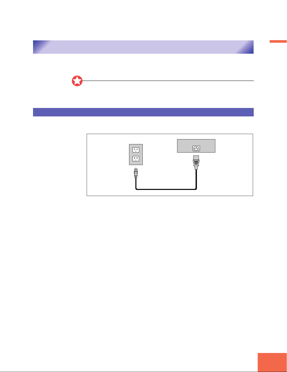
Connecting the Cord
Connect the supplied power cord to the AC inlet on the rear panel. Then plug the other
end of the cord into a 3-prong wall outlet.
Wall Outlet
Power Cord
Rear Panel
AC INLET
Chapter 1
Chapter 1 Setting Up
21
Page 24
Connecting the A3000 Outputs
Connecting the A3000 Outputs
This section explains how to connect the A3000 audio outputs to external devices.
Connecting the Analog Outputs
Important
• Be sure that power to the A3000 and to peripheral devices is OFF before making these
connections. Connecting devices while power is ON may result in damage to amps or
speakers.
• Digital I/O connections are available only if the optional AIEB1 board is installed.
The A3000 comes standard with the following stereo output jacks.
STEREO OUT Main analog output.
ASSIGNABLE OUT You can set the jacks to operate independently of the STEREO
OUT jacks, so that they output selected samples or programs
only . The feature is useful, for example, when you want to send
the main signal to one audio device while sending a specific
sample to a different device. But it is also possible to set these
jacks so that they output the same signal as the STEREO OUT
jacks. (☞299)
If you have installed the optional I/O expansion board (AIEB1 board), your A3000 will
include three additional ASSIGNABLE OUT pairs (ASSIGNABLE OUT jacks 1 to 6).
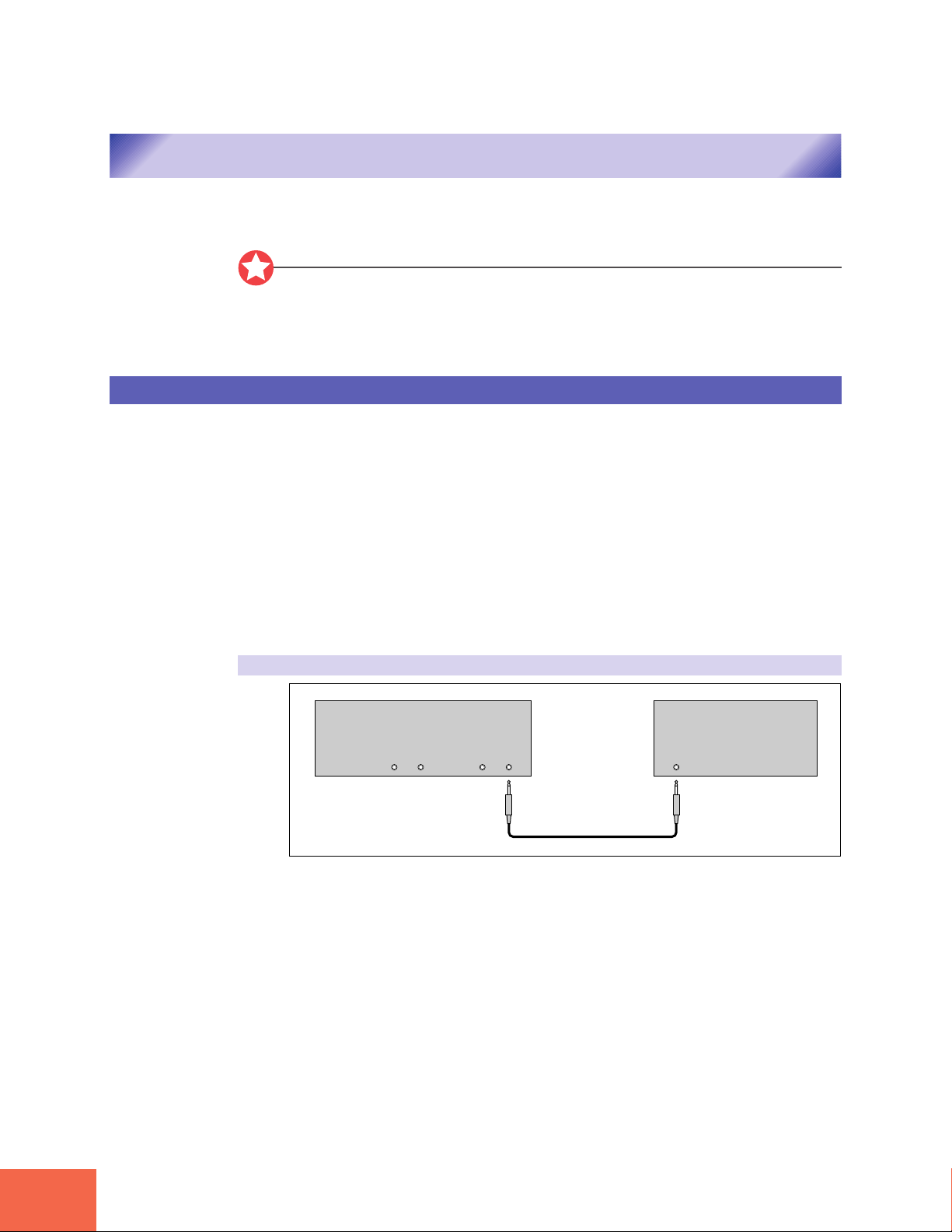
For monaural output:
A3000 Rear Panel Amp, mixer, etc.
ASSIGNABLE OUT
RL
STEREO OUT
R L/MONO
INPUT
22
Chapter 1 Setting Up
Page 25
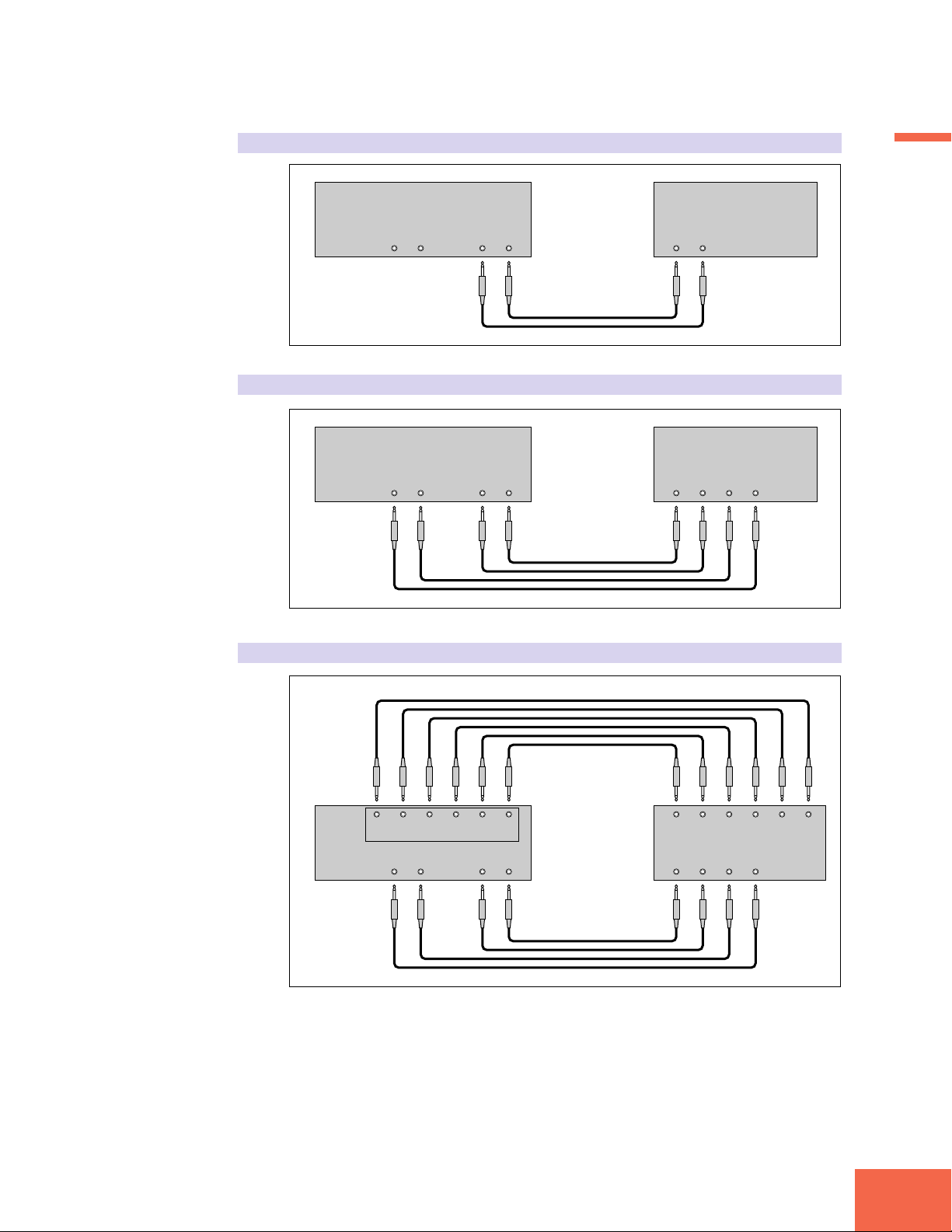
For stereo output:
A3000 Rear Panel Amp, mixer, etc.
Connecting the A3000 Outputs
ASSIGNABLE OUT
RL
STEREO OUT
R L/MONO
For assignable output:
A3000 Rear Panel Amp, mixer, etc.
ASSIGNABLE OUT
RL
STEREO OUT
R L/MONO
Assignable output using AIEB1 expansion board:
INPUT
L
INPUT 1
L
R
R L
INPUT 2
Chapter 1
R
A3000
Rear Panel
ASSIGNABLE OUT
ASSIGNABLE OUT
RL
123456
STEREO OUT
R L/MONO
Amp, mixer, etc.
LRLRLR
INPUT 3 INPUT 4 INPUT 5
INPUT 1
L
R L
INPUT 2
R
(It is not necessary, of course, to connect up all of the outputs on the expansion board.
Connect only the outputs you need to use.)
Chapter 1 Setting Up
23
Page 26
Connecting the A3000 Outputs
Connecting the Digital Outputs
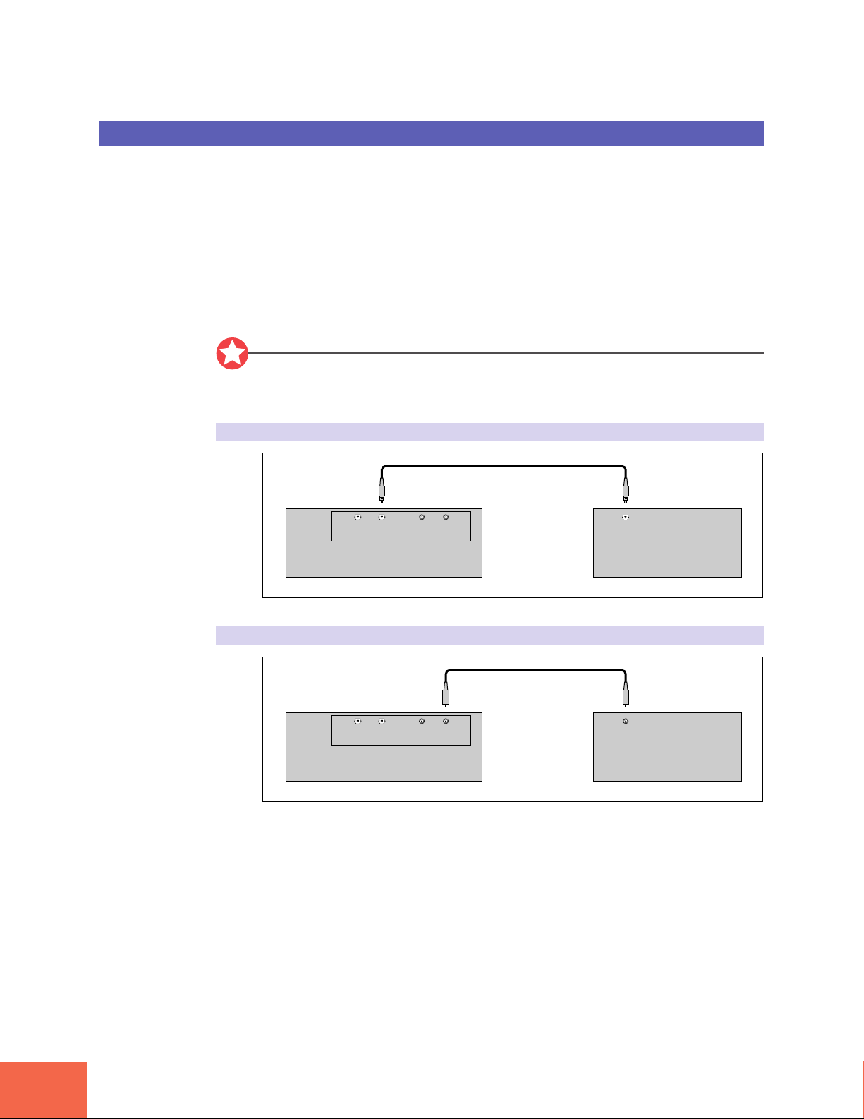
OPTICAL output connection
You can add digital I/O capacity to the A3000 by installing the optional I/O expansion
board (AIEB1 board). The board enables direct digital output of A3000 playback and
digital through-put.
For purposes of compatibility, the AIEB1 board includes two different output types:
OPTICAL OUT (optical fiber) and DIGITAL OUT (coaxial cable). Note that both of these
outputs always produce identical signals.
The digital outputs function as assignable outputs. You can set them to output selected
samples or programs, or you can set them to produce the same output as the STEREO
OUT jacks (by setting the To AsgnOut parameter to DIG&OPT; ☞299).
Important
The OPTICAL connectors are protected by plastic covers. You must remove the cover
before connecting the cable. Please remember to replace the cover when you disconnect
the cable.
A3000 Rear Panel
Coaxial output connection
A3000 Rear Panel
OUT
INOUTIN
DIGITALOPTICAL
OUT
INOUTIN
DIGITALOPTICAL
OPTICAL INPUT
Digital device
DIGITAL INPUT
Digital device
24
Chapter 1 Setting Up
Page 27
Connecting the Audio Inputs
Connecting the Audio Inputs
This section explains how to connect the A3000 to a microphone, cassette recorder, or
other sound source.
Important
• Be sure that power to the A3000 and to peripheral devices is OFF before making these
connections. Connecting devices while power is ON may result in damage to amps or
speakers.
• Digital I/O connections are available only if the optional AIEB1 board is installed.
• To select the input to be used for recording, use the Input parameter on the RecData
page (☞227).
Connecting to Analog Input
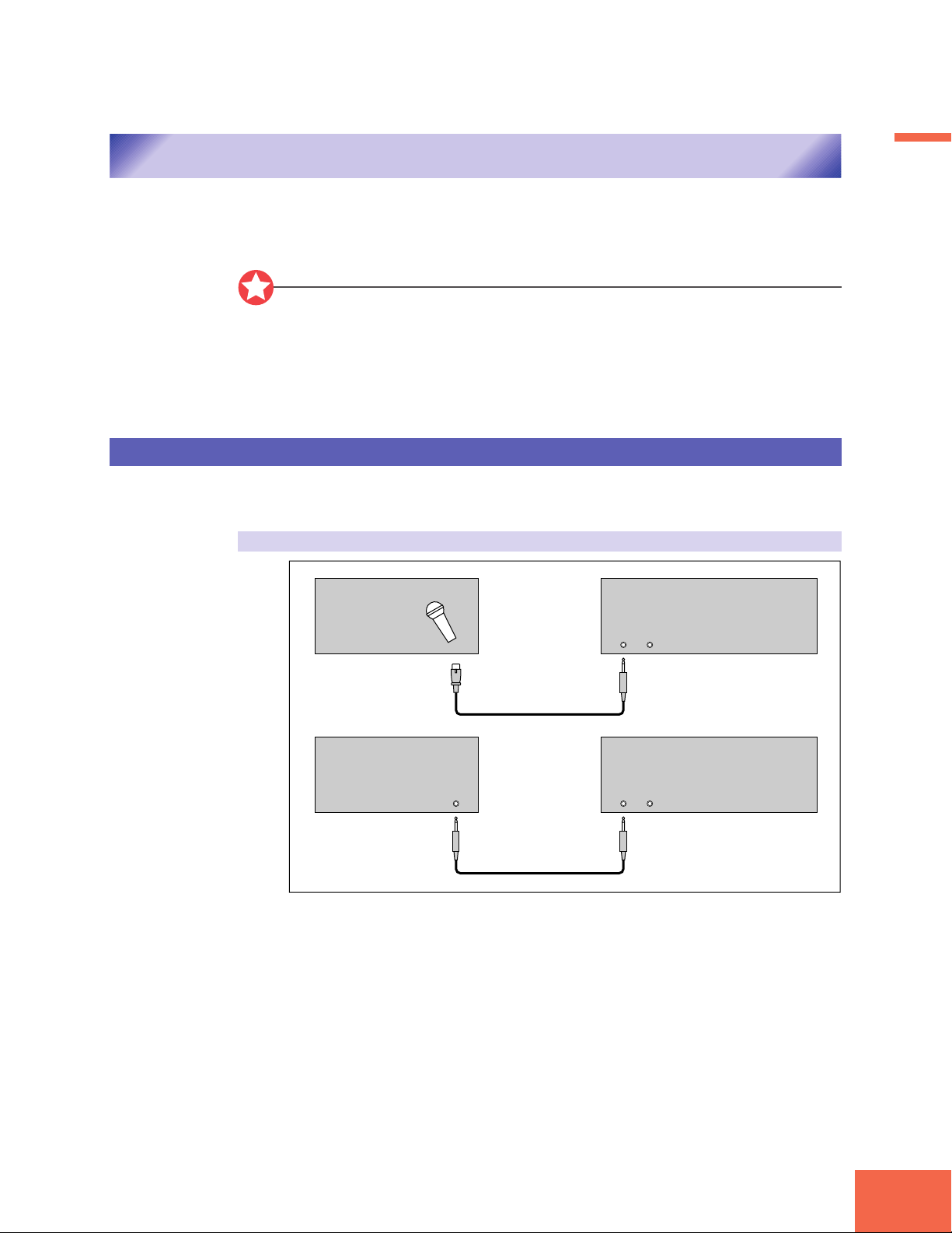
The following illustrations show how to connect to an analog input source, such as a
microphone, analog tape recorder, or analog synthesizer.
For monaural input
A3000 Front PanelMicrophone, etc.
INPUT
LR
Chapter 1
OUTPUT
A3000 Front PanelTape recorder, synth, etc.
INPUT
LR
Chapter 1 Setting Up
25
Page 28
Connecting the Audio Inputs
For stereo input
A3000 Front PanelMicrophone, etc.
INPUT
LR
A3000 Front PanelTape recorder, synth, etc.
OUTPUT
LR
Connecting to Digital Input
Installation of the optional I/O expansion board (AIEB1 board) lets you record digital
signals directly from a digital input source — such as a CD player or DAT recorder.
For purposes of compatibility, the AIEB1 board includes two different input types: OPTICAL (optical fiber) and DIGITAL (coaxial cable).
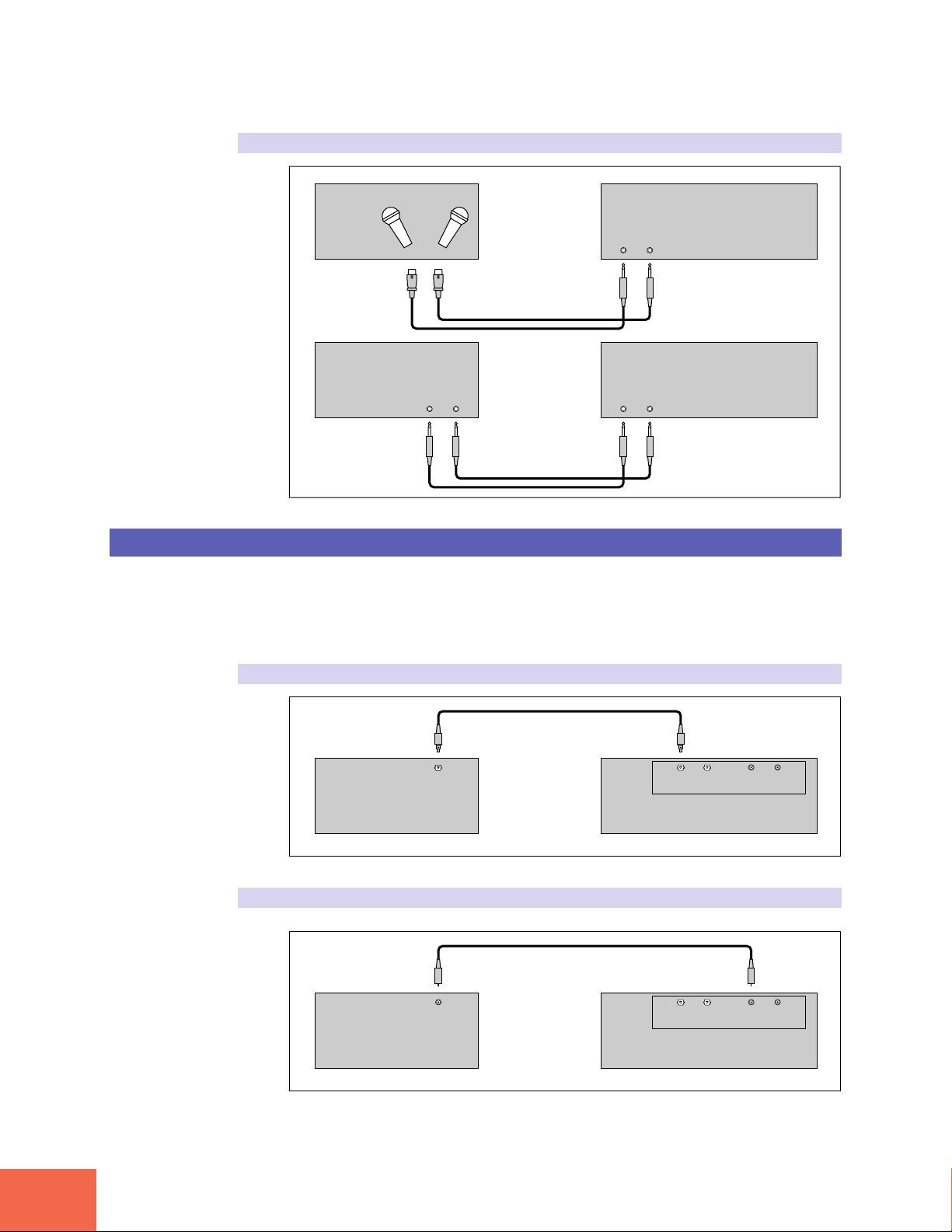
OPTICAL input connection
OPTICAL OUTPUT
INPUT
LR
A3000 Rear PanelDigital device
OUT
INOUTIN
DIGITALOPTICAL
26
Coaxial input connection
Chapter 1 Setting Up
DIGITAL OUTPUT
OUT
INOUTIN
DIGITALOPTICAL
A3000 Rear PanelDigital device
Page 29

MIDI Connections
MIDI Connections
This section explains how to connect the A3000 to MIDI devices.
Important
Be sure that power to the A3000 and to peripheral devices is OFF before making MIDI
connections. Connecting devices while power is ON may result in MIDI processing errors or unexpected and continuous sound output.
About MIDI
The following overview introduces some basic MIDI concepts. Readers familiar with
MIDI may wish to skip to “MIDI Connection Configurations,” on the next page.
What is MIDI?
MIDI (for “Musical Instrument Digital Interface”) is a standard, internationally-recognized interface for music-related digital communication among electronic instruments,
computers, sequencers, and related devices.
MIDI connectors and cables
MIDI devices provide MIDI connectors marked IN, OUT, and THRU. The IN connector
receives data from external devices, the OUT connector outputs locally produced data,
and the THRU connector relays data received at the IN connector. MIDI connections are
made by running standard MIDI cables between connectors on different devices. Each
MIDI cable connects the OUT or THRU connector of one device to the IN connector of
another device.
Chapter 1
Channels
A single MIDI cable carries up to 16 channels of performance data. If you have a MIDI
setup consisting of three keyboards outputting performance data to a fourth device, for
example, each keyboard would be transmitting data over a different channel. Each channel
is identified by its channel number (1 to 16).
Chapter 1 Setting Up
27
Page 30
MIDI Connections
MIDI Connection Configurations
Data types
Each channel can carry a variety of data types. Data types include the following.
Note data: Keys (on keyboard), and key striking force
Control change: Controller movement (modulation wheel, foot controller, etc.)
Program change: Change in voice or program
Aftertouch: Pressure applied to key after initial strike
Pitchbend: Movement of the pitchbend wheel
Bulk data: Voice and device settings and related data
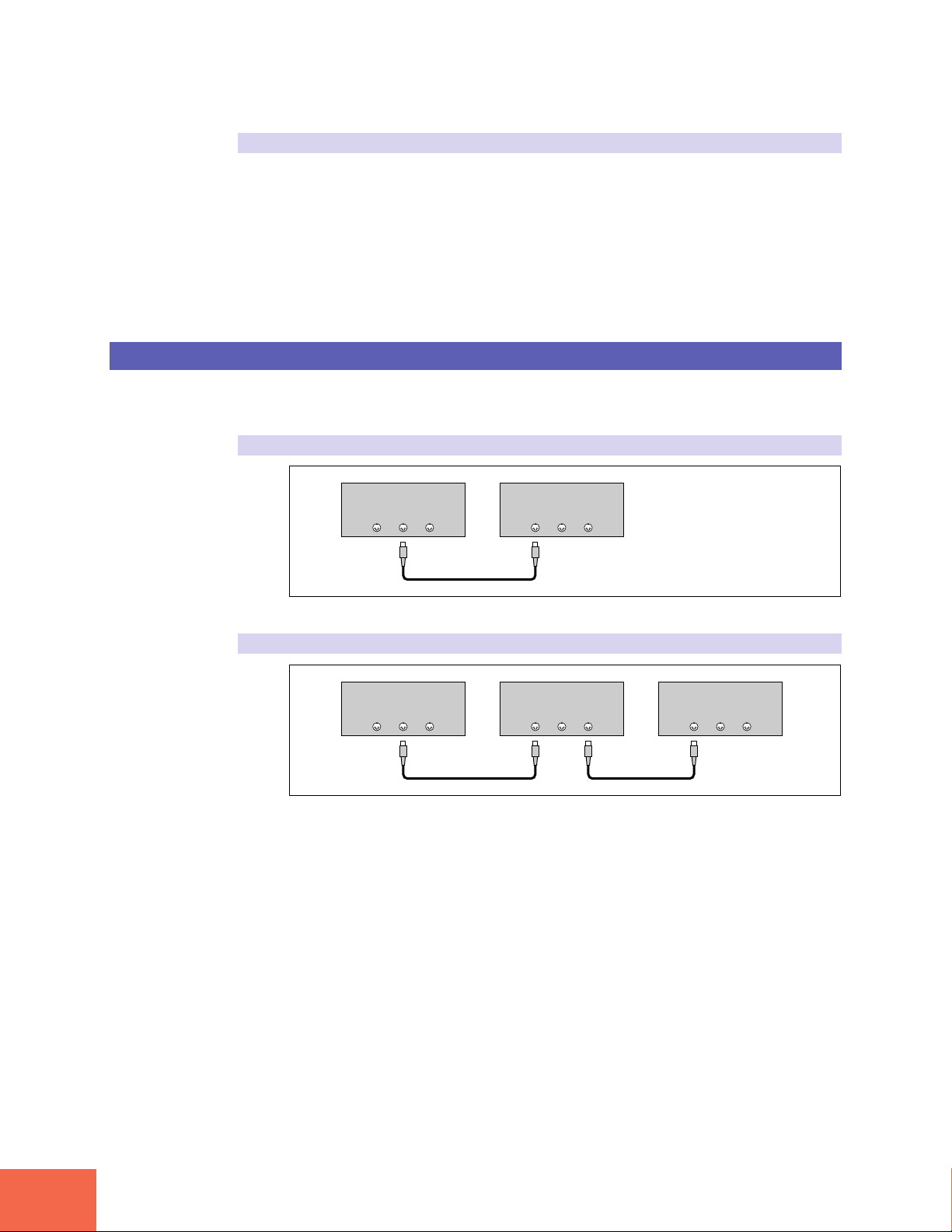
You can use MIDI connections to control the A3000 from an external keyboard, sequencer,
or computer, or to transfer A3000 data to an external MIDI device.
Connecting to keyboard or MIDI controller:
Keyboard (or controller)
MIDI
IN OUT THRU
A3000 Rear Panel
MIDI
IN OUT THRU
Connecting to keyboard/controller and external tone generator:
Keyboard (or controller)
MIDI
IN OUT THRU
A3000 Rear Panel
MIDI
IN OUT THRU
Tone generator (synthesizer, etc.)
MIDI
IN OUT THRU
28
Chapter 1 Setting Up
Page 31

Connecting to computer or sequencer:
MIDI interface
(or tone generator with
Computer
built-in interface)
MIDI
IN OUT THRU
A3000 Rear Panel
MIDI
IN OUT THRU
MIDI Connections
Chapter 1
Sequencer
IN OUT THRU
MIDI
A3000 Rear Panel
MIDI
IN OUT THRU
FYI
A wide variety of MIDI connection configurations are available. Design your setup to
suit your device and performance requirements.
Chapter 1 Setting Up
29
Page 32

Power ON/OFF
This section explains the correct procedures for powering up and powering down your equipment.
Power ON
Power ON/OFF
Important
Speakers or amplifiers should be switched on last to protect against unexpected sound
surges that may damage your equipment.
Procedure
Switch on power to external MIDI and SCSI devices.
1.
• When powering up MIDI devices, it is generally good practice (although not strictly
necessary) to switch on the transmitting-side device first.
• If you are switching on a SCSI disk or CD-ROM drive, allow the drive a few seconds to
get up to speed before proceeding to Step 2.
2.
3.
Power OFF
Switch on the power to the A3000. (Press the POWER switch on the front
panel.)
Switch on power to speakers and other audio devices.
Important
• Like other samplers, the A3000 stores all new data into main memory only, and will
lose all of this data when you switch off the power. You must therefore save all important data to disk before turning the A3000 off.
• Speakers or amplifiers should be switched off first to protect against unexpected sound
surges that may damage your equipment.
30
Chapter 1 Setting Up
Page 33

Procedure
Switch off the amplifiers or speakers.
1.
Switch off the power to the A3000. (Press the POWER switch on the front
2.
panel.)
Switch off external MIDI and SCSI devices.
3.
Power ON/OFF
Chapter 1
Chapter 1 Setting Up
31
Page 34

Sound Check
The next procedure takes you though a simple sound check that you can use to confirm proper
connection of external audio and MIDI devices. The procedure assumes that you are using a MIDI
keyboard to control A3000 playback.
Sound Check
Procedure
Switch on power to all devices as described above.
1.
Turn the MASTER VOL knob on the front panel to approximately middle position.
2.
Adjust the volume of the speakers or amplifiers.
3.
Set the Transmit Channel of your controlling MIDI keyboard to “1”.
4.
The A3000’s “Basic Receive Channel” is set to “1” at time of shipping. This means that
the A3000 is set to receive data over MIDI Channel 1.
Confirm that the PLAY-mode lamp is lit.
5.
If necessary, press the PLAY button so that the lamp comes on.
PLAY
EDIT
REC
DISK
UTILITY
PROGRAM
TRIM / LOOP
RECORD
PROGRAM
TOTAL EQ
SAMPLE
MAP / OUT
SETUP
SAMPLE
PANEL PLAY
EASY EDIT
FILTER
METER
SEQUENCE
SEQUENCE
EFFECT
EG
EFFECT
VOLUME
MASTER
SETUP
LFO
EXT CTRL
DISK
SYSTEM
CONTROL
MIDI / CTRL
MONITOR
IMPORT
MIDI
Press the second function key (counting from the left).
6.
PLAY
EDIT
REC
DISK
UTILITY
PROGRAM
TRIM / LOOP
RECORD
PROGRAM
TOTAL EQ
SAMPLE
MAP / OUT
SETUP
SAMPLE
PANEL PLAY
EASY EDIT
FILTER
METER
SEQUENCE
SEQUENCE
EFFECT
EG
EFFECT
VOLUME
MASTER
SETUP
LFO
EXT CTRL
DISK
SYSTEM
CONTROL
MIDI / CTRL
MONITOR
IMPORT
MIDI
32
Chapter 1 Setting Up
Page 35

▼The SmpSel (sample select) page should now appear. (The name SmpSel is displayed
at the lower left of the screen.)
If the screen is showing a different page, turn Knob 1 until SmpSel appears.
Turn Knob 4 one click to the right, so that the ToPgm setting changes to on.
7.
At power-on, the A3000 automatically generates several basic samples. In this example,
we will play the sine wave sample.
Sound Check
Chapter 1
8.
9.
10.
11.
Play some keys on your MIDI keyboard.
The A3000 should produce a “sine wave” sound when you play the keys. If you hear this
sound, the check is successful and you can proceed to Step 9.
• If you do not hear any sound, try pressing the [AUDITION] key on the front panel. If
this produces sound, then there is a problem with your MIDI connection or settings.
If the [AUDITION] key also fails to generate sound, then the problem is with your
speaker or amplifier connection. In either case, you should now switch off the power
to all devices, check the connections and settings, and then try again. (Be sure to
switch devices on and off in the correct order, as described in the previous two Procedures.)
Turn the volume at your speakers (or amplifiers) to minimum level.
Turn the MASTER VOL dial all the way to the left (minimum setting).
Switch off power to all devices, in the correct order (speakers first, then the
A3000, and then MIDI and SCSI devices).
Chapter 1 Setting Up
33
Page 36

34
Chapter 1 Setting Up
Page 37

2
2
Chapter 2
Trying It Out
Page 38

Introduction
This chapter takes you through a mini-tutorial that will help you become familiar with basic
operating methods and give you some initial hands-on experience with your A3000. The practice
provided here should help you gain rapid mastery of A3000 operating procedures.
Tutorial Flow
Introduction
The chapter progresses through a coordinated sequence of operations, as outlined below.
Starting Out
Recording
Playback
Deleting and Redoing
Next Step
More Recording
Changing the Sample Names
Setting the Original Key and the Key Range
Sample Editing
Using Loops
Using a Filter
Using an Envelope Generator
Using the LFO
Program Editing
Using Effects
Editing a Different Program
Sequence Play
Recording the Sequence
Playing the Sequence
Saving and Reloading Your Data
36
Formatting a Floppy Disk
Saving Your Data
Loading Data from Disk
Chapter 2 Trying It Out
Page 39

Accompanying Disks
Floppy Disks
CD-ROM
Things You Will Need
You will need following equipment to carry out the trials described in this chapter.
Please refer to Chapter 1 for information about how to connect the devices. (☞21 to 29)
• A3000
• Powered speakers, or headphones, To listen to sound generated by the A3000.
or other audio device
• Microphone (stereo or monaural) To record samples into the A3000.
• MIDI keyboard or controller To input performance data into the A3000.
• Floppy disk (Yamaha MF2HD, To save samples and programs created at the A3000.
or other 2HD disk preferably new)
Important
• Set the “MIDI Transmit Channel” on your MIDI device to “1”.
• Descriptions in this chapter assume that you have not changed A3000 settings from
their factory default values. Operation may not match the descriptions if settings
have been changed.
Introduction
Chapter 2
Chapter 2 Trying It Out
37
Page 40

Starting Out
This section guides you through the easiest procedure for recording and replaying a sample.
Recording
Starting Out
We begin with a short vocal recording — a 2-second, continuous ahhhh sound— that
you will record through a microphone. In subsequent sections you will record other
vocal samples, and then learn how to edit the samples and put them together.
Procedure
Switch on power to the A3000 and connected devices. Be sure to switch on
1.
your devices in the correct sequence.
For information about the appropriate power-on sequence, refer to Chapter 1. (☞30)
▼The screen should now look like this.
Select REC mode, SETUP function.
2.
Press the RECORDING mode button (REC button), and then press the second function
key.
PLAY
EDIT
REC
DISK
UTILITY
▼The RecData page appears.(The name “RecData” appears at the lower left of the screen.)
If the above page does not appear, try turning Knob 1 as necessary to produce it.
Memo
• Each operation is identified by its mode and function. You begin the operation by pressing the
appropriate mode button (along the left), followed by the function key (along the top), so that the
corresponding screen (or page) appears. Note that you do not need to press the mode button if the
mode is already selected — the mode remains effective until you change it.
• Most screens include a descriptive screen name at the lower left corner.
PROGRAM
TRIM / LOOP
RECORD
PROGRAM
TOTAL EQ
SAMPLE
MAP / OUT
SETUP
SAMPLE
PANEL PLAY
EASY EDIT
FILTER
METER
SEQUENCE
SEQUENCE
EFFECT
EG
EFFECT
VOLUME
MASTER
SETUP
LFO
EXT CTRL
DISK
SYSTEM
CONTROL
MIDI / CTRL
MONITOR
IMPORT
MIDI
38
Chapter 2 Trying It Out
Page 41

Turn Knob 2 to select the input.
3.
The Input setting selects the input to be recorded. The A3000 records only the signal
carried through the connector(s) that you select here.
• If you are recording from a monaural microphone connected to the “L” input on the
front panel, select AD L.
• If you are recording from a stereo microphone connected to both the “L” and “R”
inputs, select AD L/R.
Memo
• After selecting the appropriate function screen (page), you adjust the various settings by rotating
the appropriate knobs. Each knob controls a different setting. Above each knob you will see the
name of the setting it controls (on the top line of the screen), and the currently selected value (on
the second line). Turning the knob changes the value shown in the second line.
• If you have installed the optional AIEB1 I/O expansion board, you will also be able to select
DIGITAL or OPTICAL as your input source.
Starting Out
Chapter 2
Turn Knob 3 to set the sample type (SmpType) to Mono.
4.
This setting selects the type of sample to be recorded: either monaural or stereo. In this
example, we will create a monaural sample. (Note that the Mono setting forces a monaural recording, even if you are supplying your input through a stereo microphone.)
Turn Knob 1 to the right one click to advance to the Target page.
5.
You use this page to set the recording method and sample name, and to select whether
the recorded sample is to be associated with the current program.
▼The screen now looks like this.
Chapter 2 Trying It Out
39
Page 42

Starting Out
Memo
Notice that the SETUP function we are working with consists of a number of different pages. In
general, most functions comprise multiple pages. You can always switch among these pages by
turning Knob 1. (As an alternative, you can also switch pages by pressing the currently lit function
key.)
Be sure that the ToPgm (“To Program”) setting, above Knob 5, is on.
6.
Memo
• Note that samples are intended to serve as constituents of a more complex sound, or program.
The only way to play a sample, in fact, is to place it into a program. By setting the ToPgm value to
on, you are telling the A3000 to place the newly recorded sample into the currently selected
program, so that you will be able to play it back immediately after recording.
For more information about the relation between samples and programs, refer to Chapter 3. (☞70)
• Notice that the A3000 automatically assigns the default name _NewSample to the sample that
you are about to record. Although you can change this name either before or after recording, in
this example we will leave the name as it is.
Turn Knob 1 to the right two more clicks to move to the Trigger page.
7.
▼Your screen should look like this.
Turn Knob 2 to set StartBy to ManOnly (manual only).
8.
▼ The screen now looks like this.
Memo
The StartBy setting selects the trigger that will start the recording. The ManOnly setting means that
the A3000 will not begin recording until you push the >START knob. If you set the value to SrcIn, the
A3000 will begin recording immediately when the input level reaches some preset trigger level.
(☞234)
40
Chapter 2 Trying It Out
Page 43

Press the third function key.
9.
▼The Meter screen appears.
Starting Out
10.
11.
12.
Chant a continuous ahhhh sound into microphone while adjusting the REC
VOL knob (on the left side of the front panel) and watching the movement of
the meter bar. Adjust so that the bar approaches but stays within the outlined
limits.
Memo
• If the input volume is too high, the bar reaches the end of the limit area and a [C] mark appears at
the right of the bar to indicate that clipping has occurred. Lower the volume so that the [C] no
longer appears.
• Be sure to speak loudly enough (and hold the mike close enough) to generate a sufficient level on
the meter.
Press the first (leftmost) function key.
▼The Record screen appears.
Press Knob 5 (>Go).
Chapter 2
13.
Memo
Note that only certain knobs have “push” capability for each screen. The red lamp (push lamp)
directly above each knob indicates whether a push operation is currently assigned. If the lamp is ON,
pushing the knob will generate the action indicated on the screen. If the lamp is OFF, pushing the
knob has no effect.
Face the microphone and get ready to record. When you are ready, press Knob
4 (>START) and start recording an ahhhh sound. Record for about 2 seconds,
then press Knob 5 (>FINISH) to end the recording.
Try to make a steady, continuous sound, while keeping pitch and volume fairly constant.
Later we will see how to build this sound into a loop.
▼The screen shown at Step 11 above reappears when recording is finished.
Chapter 2 Trying It Out
41
Page 44

Starting Out
Playback
We will now proceed to play the sample that we have just recorded.
Procedure
Select PLAY mode, and then select the PROGRAM function.
1.
PLAY
EDIT
REC
DISK
UTILITY
PROGRAM
TRIM / LOOP
RECORD
PROGRAM
TOTAL EQ
SAMPLE
MAP / OUT
SETUP
SAMPLE
PANEL PLAY
EASY EDIT
FILTER
METER
SEQUENCE
SEQUENCE
EFFECT
EG
EFFECT
VOLUME
MASTER
SETUP
LFO
EXT CTRL
DISK
SYSTEM
CONTROL
MIDI / CTRL
MONITOR
IMPORT
MIDI
▼The screen looks like this.
Although it is possible to play samples when working at other pages, in most cases you
want to use this page to start the replay.
Strike a key on your MIDI keyboard.
2.
Striking the key should cause your sample to play back. If you did not hear anything,
check the speaker and MIDI connections. You may also need to adjust the MASTER VOL
on the A3000 (the far left dial on the front panel), or the output level on your speakers.
Memo
Notice that you play a program, rather than a specific sample. In this case, you are playing program
Pgm001, which is set up to play the sample that you just recorded (_NewSample).
• If you are not happy with the recording results, turn to the next page for information
about how to delete the sample so that you can record it again. If you are pleased with
the result, you are ready to proceed to the “Next Step” section, starting on page 45.
• If you wish to stop for a while and switch off the power, note that your recorded
sample will be lost unless you first save it to disk. You can save the sample by inserting a formatted floppy disk into the drive, then proceeding as described on pages 64 to
66. When you are ready to resume operation, please reload the data from the disk
(☞67) and then proceed to the “Next Step” section (☞45).
42
Chapter 2 Trying It Out
Page 45

Deleting and Redoing
If the recording results are not satisfactory, please use the following procedure to delete
the recorded sample. Then record the sample again as described in the previous section.
Procedure
Select PLAY mode, and then select the SAMPLE function (second function
1.
button).
Starting Out
Chapter 2
PLAY
EDIT
REC
DISK
UTILITY
PROGRAM
TRIM / LOOP
RECORD
PROGRAM
TOTAL EQ
SAMPLE
MAP / OUT
SETUP
SAMPLE
PANEL PLAY
EASY EDIT
FILTER
METER
SEQUENCE
SEQUENCE
EFFECT
EG
EFFECT
VOLUME
MASTER
SETUP
LFO
EXT CTRL
DISK
SYSTEM
CONTROL
MIDI / CTRL
MONITOR
IMPORT
MIDI
▼ The screen looks like this.
Press the COMMAND key.
2.
Memo
The COMMAND key calls up a command screen that you use to execute a specific command. The
command that appears depends on the current mode and function.
Turn Knob 1 to select the >DELETE page.
3.
Be sure that Type (Knob 2) is set to Smp.
4.
If necessary, turn Knob 2 to change the setting to Smp.
Turn Knob 4 to select the name of the sample to be deleted.
5.
In this case, you want to set the value to _NewSample.
Chapter 2 Trying It Out
43
Page 46

Starting Out
Press Knob 1 (>DELETE).
6.
▼The following confirmation prompt appears.
Press Knob 5 (>YES) to execute the deletion.
7.
The new sample is now deleted. You can record it again as described above.
Memo
In practice, it is not necessary to manually delete the sample as described here in order to replace it
with a new one. You may instead record a new sample directly over the current sample, as explained
later in this manual (☞230).
44
Chapter 2 Trying It Out
Page 47

Next Step
Next Step
In this section we record two more samples, a continuous eeeee sound and a continuous ohhhh
sound. We will then assign a name, an original key, and a key range to each of these samples.
Finally, we will try out the split keyboard feature.
More Recording
We begin by recording an eeeee and an ohhhh sample.
Procedure
Select REC mode, SETUP function.
1.
Press the RECORD mode button (REC button), and then press the second function key.
Turn Knob 1 to select the Target page.
2.
▼The screen should now look like this.
PLAY
EDIT
REC
DISK
UTILITY
PROGRAM
TRIM / LOOP
RECORD
PROGRAM
TOTAL EQ
SAMPLE
MAP / OUT
SETUP
SAMPLE
PANEL PLAY
EASY EDIT
FILTER
METER
SEQUENCE
SEQUENCE
EFFECT
EG
EFFECT
VOLUME
MASTER
SETUP
LFO
EXT CTRL
DISK
SYSTEM
Chapter 2
CONTROL
MIDI / CTRL
MONITOR
IMPORT
MIDI
Turn Knob 2 to set Sample to New+.
3.
Memo
Select New+ when you want to record two or more new samples in succession.
Press the first (leftmost) function key.
4.
▼The Record screen appears.
Chapter 2 Trying It Out
45
Page 48

Next Step
Press Knob 5 (>Go).
5.
Face the microphone and get ready to record. When you are ready, press Knob
6.
4 (>START) and start recording an eeeee sound. Record for about 2 seconds,
and then press Knob 5 (>FINISH) to end the recording.
▼The eeeee sound is now recorded.
Face the microphone and get ready to record again. Press Knob 4 (>START)
7.
and start recording an ohhhh sound. Continue for about 2 seconds, and then
press Knob 5 (>FINISH).
▼The screen shown at step 4 reappears when recording is finished.
Play a note on your MIDI keyboard.
8.
Pressing the note should cause all three of your samples to play out together.
• If you are unhappy with your two new samples, you can delete them both by pushing
Knob 2 (>ALLDEL), and then pressing Knob 5 (>YES) to confirm. Then record them
again as described above.
• If you want to redo only one of the two new samples, delete the bad sample using the
procedure given on page 43 above (“Deleting and Redoing”). Note that you will need
to select the sample by its names. Sample names are described immediately below.
Memo
Each time you record a sample under an already existing sample name, the A3000 appends a sequential number to the end of the name. Since you have used the default name for all samples, the
A3000 set the name for your first sample (ahhhh) to_NewSample, the name for your second recorded sample (eeeee) to _NewSample 1, and the name for your third recorded sample (ohhhh) to
_NewSample 2.
46
Chapter 2 Trying It Out
Page 49

Changing the Sample Names
The A3000 has set non-descriptive default names for your new samples: _NewSample,
_NewSample 1, and _NewSample 2. We will now change the names to Voice AH,
Voice EE, and Voice OH, respectively.
Procedure
Next Step
Select PLAY mode, SAMPLE function.
1.
PLAY
EDIT
REC
DISK
UTILITY
Turn Knob 1 to select the SmpSel (Sample Select) page.
2.
▼The screen should now look like this.
Turn Knob 2 or Knob 3 to select _NewSample as the sample.
PROGRAM
TRIM / LOOP
RECORD
PROGRAM
TOTAL EQ
SAMPLE
MAP / OUT
SETUP
SAMPLE
PANEL PLAY
EASY EDIT
FILTER
METER
SEQUENCE
SEQUENCE
EFFECT
EG
EFFECT
VOLUME
MASTER
EXT CTRL
SYSTEM
3.
Press Knob 2 or Knob 3.
4.
SETUP
LFO
DISK
Chapter 2
CONTROL
MIDI / CTRL
MONITOR
IMPORT
MIDI
Turn Knob 3 to select <DELETE>.
5.
Chapter 2 Trying It Out
47
Page 50

Next Step
Press Knob 3 as many times as necessary to delete all of the characters in the
6.
name.
▼The name field should now be empty.
Turn Knob 2 to select V.
7.
Press Knob 2 (<ENTER>) to enter the new character and move the cursor one
8.
space to the right.
9.
10.
11.
12.
Repeat steps 7 to 8 in order to enter the rest of the name. Please set the name
to Voice AH.
Note that you will need to enter a space character between the “e” and the “A”. You can
do this by pressing Knob 1 once (without turning Knob 2) after inputting the “e”.
Press Knob 5 (>OK).
▼This completes the name change. The original screen now reappears.
Turn Knob 2 or Knob 3 to select _NewSample 1.
Press Knob 2 or Knob 3.
48
Chapter 2 Trying It Out
Page 51

Next Step
13.
14.
15.
16.
Turn Knob 3 to select <PASTE>.
Press Knob 3 (<PASTE>).
▼The name that you just entered (Voice AH) is “pasted” into the name field.
Chapter 2
Memo
Use the paste function to simplify the work of entering names. This feature lets you reinput a previous character string with a single press on the knob.
Turn Knob 1 to move the cursor to the next to last letter of the displayed name
(A).
Turn Knob 2 to change the A into an E. Then turn Knob 1 to advance to the
last letter (H), and turn Knob 2 again to change this into another E.
17.
18.
Press Knob 5 (>OK).
▼ This completes the name change. The original screen reappears.
Now repeat Steps 11 to 17 to change the name for your third sample from
_NewSample 2 to Voice OH.
Chapter 2 Trying It Out
49
Page 52

Next Step
Setting the Original Key and the Key Range
Notice that striking a key on your MIDI keyboard will replay all three of your samples at
the same time. For our first “sample edit” session, we will now set the samples so that
keyboard keys from C2 to B2 produce Voice AH, while keys C3 to B3 produce Voice EE,
and keys C4 to B4 produce Voice OH.
Procedure
Select EDIT Mode, and then select the MAP/OUT function.
1.
PLAY
EDIT
REC
DISK
UTILITY
PROGRAM
TRIM / LOOP
RECORD
PROGRAM
TOTAL EQ
SAMPLE
MAP / OUT
SETUP
SAMPLE
PANEL PLAY
EASY EDIT
FILTER
METER
SEQUENCE
SEQUENCE
EFFECT
EG
EFFECT
VOLUME
MASTER
SETUP
LFO
EXT CTRL
DISK
SYSTEM
CONTROL
MIDI / CTRL
MONITOR
IMPORT
MIDI
Turn Knob 1 to select the KeyRnge page.
2.
▼The screen should now look like this.
Press Knob 1.
3.
▼The following screen appears.
Memo
Y ou use this screen to select the program or sample that you want to edit. Always go to this screen to
select the appropriate item before you begin editing.
50
4.
5.
Chapter 2 Trying It Out
Turn Knob 2 or 3 to select the Voice AH sample for editing.
▼Be sure that Voice AH is selected.
Press Knob 1 again.
▼The initial KeyRnge screen reappears.
Page 53

Turn Knob 2 to set the OrigKey (original key) value to C2. Then turn Knob 3
6.
to set Low to C2, and turn Knob 4 to set High to B2.
▼As you can see, the “original key” is now set to C2, while the key range is C2 to B2.
Next Step
7.
8.
9.
10.
Press Knob 1, and then turn Knob 2 or Knob 3 to select Voice EE for editing.
Then press Knob 1 again.
Turn Knob 2 to set OrigKey to C3. Then turn Knob 3 to set Low to C3, and
turn Knob 4 to set High to B3.
• Note that in actual recording work you would want to set the original key to the
sample’s true pitch. In this practice session, however, we will set an imprecise value
for the sake of convenience.
▼The “original key” is now set to C3. The key range is C3 to B3.
Press Knob 1, and then turn Knob 2 or Knob 3 to select Voice OH for editing.
Then press Knob 1 again.
Set OrigKey to C4; set Low to C4; and set High to B4.
▼The “original key” is now set to C4. The key range is C4 to B4.
Chapter 2
11.
Now try playing at the MIDI keyboard.
▼Notice that each key in the C2 - B2 octave produces the ahhhh sound. Keys C3 to B3
produce the eeeee sample, while keys C4 to B4 play the ohhhh sample.
Memo
Notice how this procedure lets you map the different samples in a program to specific areas of the
keyboard.
In the next section we will proceed to try out more sophisticated editing of your three
samples.
If you wish to stop here for a while and switch off the power, please save your edited data
to floppy disk (☞64 to 66). When you are ready to resume operation, please reload the
data from the disk (☞67) and then proceed to the next page.
Chapter 2 Trying It Out
51
Page 54

Sample Editing
In this section we will try out further editing on your ahhhh, eeeee, and ohhhh samples.
Using Loops
Sample Editing
We will now set up a loop for the ahhhh sample. The sample will then play out continuously when you hold down an appropriate key at the MIDI keyboard.
Procedure
Select EDIT mode, and then select the TRIM/LOOP function.
1.
PLAY
EDIT
REC
DISK
UTILITY
PROGRAM
TRIM / LOOP
RECORD
PROGRAM
TOTAL EQ
SAMPLE
MAP / OUT
SETUP
SAMPLE
PANEL PLAY
EASY EDIT
FILTER
METER
SEQUENCE
SEQUENCE
EFFECT
EG
EFFECT
VOLUME
MASTER
SETUP
LFO
EXT CTRL
DISK
SYSTEM
CONTROL
MIDI / CTRL
MONITOR
IMPORT
MIDI
Press Knob 1, and then turn Knob 2 or Knob 3 to select the Voice AH sample
2.
for editing. Then press Knob 1 again.
Turn Knob 1 to select the WvMode (wave mode) screen.
3.
▼The screen should now look like this.
Turn Knob 2 to set LpMode (loop mode) to –␣ –␣ –␣ → O.
4.
52
5.
Chapter 2 Trying It Out
Press and hold the AUDITION key.
You use the AUDITION key to play out the currently selected sample. Notice how the
sound loops: ahhhh, ahhhh, ahhhh. In the next few steps we will adjust the loop start
and end points to produce a smoother loop (ahhh-hhh-hhh).
Page 55

Memo
Notice that you can use the AUDITION key in place of the MIDI keyboard to play out the sound of
your samples.
Turn Knob 1 to select the Config (Configure) screen. Then turn Knob 3 to set
6.
Zero to on.
The zero feature (also known as automatic zeroing) eliminates the cracking sound that
may occur when playback jumps from the loop endpoint to the loop start point.
▼The screen now looks like this.
Turn Knob 1 to select the Loop screen. Then turn Knob 4 to set Step to ×1000
7.
and turn Knob 2 as necessary to set LpStart (loop start point) to approximately
30000.
Sample Editing
Chapter 2
8.
9.
10.
Turn Knob 3 as necessary to set LpEnd (loop endpoint) to approximately 45000.
Hold down the AUDITION key to check the editing results.
Adjust the start and endpoint values as necessary to further improve the sound of the
loop.
Now play a key between C2 and B2 at your keyboard.
The key should produce the sound of the edited ahhh-hhh-hhh sample. The sound should
continue until the key is released.
Chapter 2 Trying It Out
53
Page 56

Sample Editing
Using a Filter
We will now set up a filter for the eeeee sample. The filter settings should produce a
significant change in the sample’s sound.
Procedure
Select EDIT mode, and then select the FILTER function.
1.
PLAY
EDIT
REC
DISK
UTILITY
PROGRAM
TRIM / LOOP
RECORD
PROGRAM
TOTAL EQ
SAMPLE
MAP / OUT
SETUP
SAMPLE
PANEL PLAY
EASY EDIT
FILTER
METER
SEQUENCE
SEQUENCE
EFFECT
EG
EFFECT
VOLUME
MASTER
SETUP
LFO
EXT CTRL
DISK
SYSTEM
CONTROL
MIDI / CTRL
MONITOR
IMPORT
MIDI
Press Knob 1, and then turn Knob 2 or Knob 3 to select the Voice EE sample
2.
for editing. Then press Knob 1 again.
Turn Knob 1 to select the Filter screen. Then turn Knob 2 to set Type to HiPass1.
3.
Turn Knob 3 to set Cutoff to 100.
▼The screen should now look like this.
Now play a key between C3 and B3 at your keyboard.
4.
▼Notice how the filter has eliminated the low-frequency components of the eeeee sound.
Memo
The A3000 offers a variety of filter types. You can select from among two high-pass filters (HiPass1,
HiPass2), two low-pass filters (LowPass1, LowPass2), a band-pass filter (BandPass), and a bandeliminate filter (BandElim).
54
Chapter 2 Trying It Out
Page 57

Using an Envelope Generator
We will now adjust the amplitude EG to lengthen the release rate of the ohhhh sample.
The “release” determines how long the sample sound lingers after you stop playing the
key at the keyboard.
Procedure
Sample Editing
Select EDIT mode, and then select the EG (envelope generator) function.
1.
PLAY
EDIT
REC
DISK
UTILITY
Press Knob 1, and then turn Knob 2 or Knob 3 to select the Voice OH sample
2.
for editing. Then press Knob 1 again.
Turn Knob 1 to select the AEG (amplitude envelope generator) screen. Then
3.
turn Knob 5 to set the RelRate value to 40.
▼The screen should now look like this.
PROGRAM
TRIM / LOOP
RECORD
PROGRAM
TOTAL EQ
SAMPLE
MAP / OUT
SETUP
SAMPLE
PANEL PLAY
EASY EDIT
FILTER
METER
SEQUENCE
SEQUENCE
EFFECT
EG
EFFECT
VOLUME
MASTER
SETUP
LFO
EXT CTRL
DISK
SYSTEM
CONTROL
MIDI / CTRL
MONITOR
IMPORT
MIDI
Chapter 2
Now play a key between C4 and B4 at your keyboard.
4.
Notice how the sound fades out slowly when you release the key.
Memo
• The AEG determines how the sample’s amplitude (sound level) develops over time. In addition to
the release-rate value, you can also set an attack rate and a sustain level. The attack rate value
determines how rapidly the sound rises when the key is first hit, while the sustain level determines how the sound continues while the key is held down.
• The A3000 also provides a filter EG (“FEG”) and pitch EG (“PEG”). You use these features to
select how filtering and pitch develop over time while the key is held down.
Chapter 2 Trying It Out
55
Page 58

Sample Editing
Using the LFO
We will now set the LFO (low-frequency oscillator) to create a vibrato in the ahhhh
sample.
Procedure
Select EDIT mode, LFO function.
1.
PLAY
EDIT
REC
DISK
UTILITY
PROGRAM
TRIM / LOOP
RECORD
PROGRAM
TOTAL EQ
SAMPLE
MAP / OUT
SETUP
SAMPLE
PANEL PLAY
EASY EDIT
FILTER
METER
SEQUENCE
SEQUENCE
EFFECT
EG
EFFECT
VOLUME
MASTER
SETUP
LFO
EXT CTRL
DISK
SYSTEM
CONTROL
MIDI / CTRL
MONITOR
IMPORT
MIDI
Press Knob 1, and then turn Knob 2 or Knob 3 to select the Voice AH sample
2.
for editing. Then press Knob 1 again.
Turn Knob 1 to select the PtchMod (pitch modulation) screen. Then turn
3.
Knob 2 to set the Depth to 30.
▼The screen now looks like this.
Turn Knob 1 to select the Common screen. Turn Knob 2 to set Wave to
4.
Triangl. Turn Knob 3 to set Speed to 15; turn Knob 4 to set Delay to 90.
56
5.
Chapter 2 Trying It Out
Now play and hold a key between C2 and B2 at your keyboard.
Notice how a gentle vibrato (pitch waver) begins after the sound has been held for a few
moments.
In the next section we will begin to do some program editing.
If you wish to stop here for a while and switch off the power, please save your edited data
to floppy disk (☞64 to 66). When you are ready to resume operation, please reload the
data from the disk (☞67) and then proceed to the next page.
Page 59

Program Editing
This section introduces you to some basic program-editing procedures.
Using Effects
ProgramEditing
We will first set up an effect for the currently selected program (Pgm 001). In particular,
we will apply a “flanging pan” effect to the eeeee sample.
Procedure
Select EDIT mode, and then select the MAP/OUT function.
1.
PLAY
EDIT
REC
DISK
UTILITY
Press Knob 1, and then turn Knob 2 or Knob 3 to select the Voice EE sample
2.
for editing. Then press Knob 1 again.
Turn Knob 1 to select the Output page. Then turn Knob 2 to set MainOut to
3.
Effect1.
▼The screen should now look like this.
PROGRAM
TRIM / LOOP
RECORD
PROGRAM
TOTAL EQ
SAMPLE
MAP / OUT
SETUP
SAMPLE
PANEL PLAY
EASY EDIT
FILTER
METER
SEQUENCE
SEQUENCE
EFFECT
EG
EFFECT
VOLUME
MASTER
SETUP
LFO
EXT CTRL
DISK
SYSTEM
CONTROL
MIDI / CTRL
MONITOR
IMPORT
MIDI
Chapter 2
Memo
The A3000 allows you to assign up to three effects (Effect1, Effect2, and Effect3) to each program.
Y ou can then apply any one of these effects to each of the samples used by the program. The MainOut
setting determines which of the effects is applied to the sample. In this case, we will apply Effect1.
Chapter 2 Trying It Out
57
Page 60

ProgramEditing
Select PLAY mode, EFFECT function.
4.
PLAY
EDIT
REC
DISK
UTILITY
PROGRAM
TRIM / LOOP
RECORD
PROGRAM
TOTAL EQ
PANEL PLAY
Turn Knob 1 to select the EfType (effect type) screen. Then turn Knob 2 to set
5.
Effect1 to FlngPan (flanging pan).
Now play a key between C3 and B3 at your keyboard.
6.
Notice how the flange effect pans back and forth from right to left.
Editing a Different Program
Now we will see how to set up and edit another program. We will leave our current
program (Pgm 001) as is, and begin work on a second program (Pgm 002).
Procedure
SAMPLE
MAP / OUT
SETUP
SAMPLE
EASY EDIT
FILTER
METER
SEQUENCE
SEQUENCE
EFFECT
EG
EFFECT
VOLUME
MASTER
SETUP
LFO
EXT CTRL
DISK
SYSTEM
CONTROL
MIDI / CTRL
MONITOR
IMPORT
MIDI
58
1.
Chapter 2 Trying It Out
Select PLAY mode, PROGRAM function.
PLAY
EDIT
REC
DISK
UTILITY
PROGRAM
TRIM / LOOP
RECORD
PROGRAM
TOTAL EQ
SAMPLE
MAP / OUT
SETUP
SAMPLE
PANEL PLAY
EASY EDIT
FILTER
METER
SEQUENCE
SEQUENCE
EFFECT
EG
EFFECT
VOLUME
MASTER
SETUP
LFO
EXT CTRL
DISK
SYSTEM
CONTROL
MIDI / CTRL
MONITOR
IMPORT
MIDI
Page 61

Turn Knob 2 or Knob 3 to set Program to 002:“Pgm 002”.
2.
▼The screen should now look like this.
Try playing at the keyboard to see what happens.
3.
Nothing happens. Program 002 is still empty, since we have not yet assigned any samples to it. So we will now proceed to assign the three samples we have already created to
this new program.
Press the second (SAMPLE) function key.
4.
If necessary, turn Knob 1 until SmpSel appears at the lower left of the screen.
ProgramEditing
Chapter 2
Turn Knob 2 or Knob 3 to select the Voice AH sample.
5.
Turn Knob 4 to set ToPgm to on.
6.
This setting selects Voice AH for use in this program.
Now turn Knob 2 or 3 to select the Voice EE sample, then turn Knob 4 to set
7.
ToPgm to on. Then turn Knob 2 or 3 again to select the Voice OH sample, and
again turn Knob 4 to set ToPgm to on.
All three samples are now selected for use with this program.
Try playing at the keyboard again.
8.
As with Program 001, keys from C2 to B2 produce the ahhhh sample, keys from C3 to
B3 play the eeeee sample, and keys from C4 to B4 play the ohhhh sample.
Chapter 2 Trying It Out
59
Page 62

ProgramEditing
Memo
• Notice that there was no need to go through this procedure for Program 001, which was ready to
play immediately after the samples were recorded. This is because you set the ToPgm setting to
on before you began to record (see page 40). This setting causes the recorded sample to map
directly to the currently selected program.
• Notice also that the keyboard ranges for all three samples are the same for both programs. This is
because the range settings are stored with the samples, not with the program. The Voice AH
sample is currently set for range C2 to B2, while Voice EE is set for C3 to B3, and Voice OH is set
for C4 to B4.
Next, let’s try dropping the pitch of Voice AH by one octave, and then raising the pitch
of Voice OH by the same amount.
One way to do this would be to lower or raise each sample’s internal pitch settings. But
this would also change the sound of Program 001, since the pitch settings are stored
with the sample and affect all programs in which the sample is used.
To limit our change to Program 002 only, we will instead use the Easy Edit feature to
adjust the pitch.
9.
10.
11.
Press the third (EASY EDIT) function key.
Press Knob 1, then turn Knob 2 or Knob 3 to select Voice AH for easy editing.
Then press Knob 1 again.
Turn Knob 2 or Knob 3 to select the Tune Coarse edit parameter.
60
Chapter 2 Trying It Out
Page 63

ProgramEditing
12.
13.
14.
15.
Turn Knob 4 or Knob 5 to set the value to -12.
Press Knob 1, then turn Knob 2 or Knob 3 to select Voice OH for easy editing.
Then press Knob 1 again.
Chapter 2
Turn Knob 4 or Knob 5 to set the coarse tune value to +12.
Try playing at the keyboard.
▼Notice that the pitch of the ahhhh is now lower by one octave, while the ohhhh is
higher by an octave.
In the next section we will try recording and playing a “sequence.”
If you wish to stop here for a while and switch off the power, please save your edited data
to floppy disk (☞64 to 66). When you are ready to resume operation, please reload the
data from the disk (☞67) and then proceed to the next page.
Chapter 2 Trying It Out
61
Page 64

Sequence Play
In this section you will learn how to record and play a sequence.
Recording the Sequence
Sequence Play
Here we will record a sequence that makes use of Program 001. Note that a sequence is
a stream of MIDI performance data that you record from your keyboard into the A3000
for later playback.
Procedure
Select PLAY mode, PROGRAM function.
1.
PLAY
EDIT
REC
DISK
UTILITY
PROGRAM
TRIM / LOOP
RECORD
PROGRAM
TOTAL EQ
SAMPLE
MAP / OUT
SETUP
SAMPLE
PANEL PLAY
EASY EDIT
FILTER
METER
SEQUENCE
SEQUENCE
EFFECT
EG
EFFECT
VOLUME
MASTER
Turn Knob 2 or Knob 3 to set Program to 001:“Pgm 001”.
2.
▼The screen looks like this.
Select UTILITY mode, SEQUENCE function.
3.
PLAY
EDIT
REC
DISK
UTILITY
PROGRAM
TRIM / LOOP
RECORD
PROGRAM
TOTAL EQ
SAMPLE
MAP / OUT
SETUP
SAMPLE
PANEL PLAY
EASY EDIT
FILTER
METER
SEQUENCE
SEQUENCE
EFFECT
EG
EFFECT
VOLUME
MASTER
SETUP
LFO
EXT CTRL
DISK
SYSTEM
SETUP
LFO
EXT CTRL
DISK
SYSTEM
CONTROL
MIDI / CTRL
MONITOR
IMPORT
MIDI
CONTROL
MIDI / CTRL
MONITOR
IMPORT
MIDI
62
▼The screen should now look like this.
If the above screen does not appear, turn Knob 1 until SeqSel appears at the lower left.
Chapter 2 Trying It Out
Page 65

Press Knob 5 (>NEW).
4.
▼The A3000 creates a new, blank sequence.
Turn Knob 1 to select the Play&Rec screen.
5.
Get ready to play a sequence at your MIDI keyboard. When you are ready, press
6.
Knob 4 (>REC) and then begin playing immediately. Play for about 10 seconds, then press Knob 5 (>STOP).
Sequence Play
Chapter 2
Playing the Sequence
Now let’s play back the sequence that you just recorded.
Procedure
Press Knob 5 (>PLAY).
1.
▼The A3000 starts replay of the recorded sequence.
Press Knob 5 (>STOP).
2.
▼The replay stops.
Chapter 2 Trying It Out
63
Page 66

Saving and Reloading Your Data
Saving and Reloading Your Data
Like other samplers, the A3000 stores all new data into main memory only, and will lose all of this
data when you switch off the power. You must therefore be sure to save all important data to disk
before turning the A3000 off. Note that “new data” here refers to all newly recorded samples and
sequences, and to all editing changes that you make to your samples and programs.
In this example, we will save the data to a 2HD-type floppy disk.
Formatting a Floppy Disk
Floppy disks must be formatted before they can be used. The format operation sets the
disk up so that it can be used for data storage and retrieval. You can format a new disk
using the procedure described below, or you can use preformatted disks.
Note that the A3000 supports the following two format types only.
• MFF2DD (2DD disk type): MS-DOS 9-sector format 720KB
• MF2HD (2HD disk type): MS-DOS 18-sector format 1.44MB
Important
The format operation erases any data already on the disk.
Procedure
Select DISK mode, DISK function.
1.
If necessary, turn Knob 1 to select the Disk page.
PLAY
EDIT
REC
DISK
UTILITY
▼The screen now looks like this.
PROGRAM
TRIM / LOOP
RECORD
PROGRAM
TOTAL EQ
SAMPLE
MAP / OUT
SETUP
SAMPLE
PANEL PLAY
EASY EDIT
FILTER
METER
SEQUENCE
SEQUENCE
EFFECT
EG
EFFECT
VOLUME
MASTER
SETUP
LFO
EXT CTRL
DISK
SYSTEM
CONTROL
MIDI / CTRL
MONITOR
IMPORT
MIDI
64
Chapter 2 Trying It Out
Page 67

Saving and Reloading Your Data
Press the COMMAND key.
2.
Insert the floppy disk you want to format into the disk drive.
3.
In this example, it is assumed that you are using a new (unformatted) HD-type disk.
Turn Knob 1 to select the FD_FMT screen.
4.
Make sure that Type is set to 2HD. (If 2HD is not already selected, turn Knob
5.
2 to select it.)
The name to be given to the formatted disk appears above Knobs 4 and 5. The default
name is “New FD”. Although you are free to change the name, we will leave the default
name unchanged for this example.
Press Knob 1 (>FD_FMT).
6.
▼The following confirmation prompt appears.
Press Knob 5 (>YES).
7.
▼The A3000 starts to format the disk. Please wait until the original screen returns,
indicating that the format is finished.
Chapter 2
Saving Your Data
The next procedure shows how to save all of your new data to floppy disk.
Important
This procedure writes all current memory content into the floppy disk, overwriting any
data already existing on the disk.
Chapter 2 Trying It Out
65
Page 68

Saving and Reloading Your Data
1.
Procedure
Select PLAY mode.
Function selection is not significant (you can execute this operation regardless of the
selected function), but in this case let’s select PROGRAM.
PLAY
EDIT
REC
DISK
UTILITY
PROGRAM
TRIM / LOOP
RECORD
PROGRAM
TOTAL EQ
SAMPLE
MAP / OUT
SETUP
SAMPLE
PANEL PLAY
EASY EDIT
FILTER
METER
SEQUENCE
SEQUENCE
EFFECT
EG
EFFECT
VOLUME
MASTER
SETUP
LFO
EXT CTRL
DISK
SYSTEM
CONTROL
MIDI / CTRL
MONITOR
IMPORT
MIDI
Press the COMMAND key.
2.
Turn Knob 1 to select the >SAVE screen.
3.
▼The screen should now look like this.
Be sure that Type is set to All(wipe). If necessary, turn Knob 2 to change the
4.
setting to this value.
Be sure that To is set to Dsk:“New FD”. If necessary, turn Knob 3 or Knob 4
5.
to change the setting to this value.
66
6.
7.
Chapter 2 Trying It Out
Press Knob 1 (>SAVE).
▼The following confirmation prompt appears.
Press Knob 5 (>YES).
▼The A3000 starts to save the data. Please wait until the original screen returns, indi-
cating that the save is finished.
Page 69

Loading Data from Disk
The section shows you to reload the saved disk data back into the A3000.
Procedure
Select DISK mode, DISK function.
1.
If necessary, turn Knob 1 to select the Disk page.
Saving and Reloading Your Data
Chapter 2
PLAY
EDIT
REC
DISK
UTILITY
PROGRAM
TRIM / LOOP
RECORD
PROGRAM
TOTAL EQ
SAMPLE
MAP / OUT
SETUP
SAMPLE
PANEL PLAY
EASY EDIT
FILTER
METER
SEQUENCE
SEQUENCE
EFFECT
EG
EFFECT
VOLUME
MASTER
SETUP
LFO
EXT CTRL
DISK
SYSTEM
CONTROL
MIDI / CTRL
MONITOR
IMPORT
MIDI
▼The screen now looks like this.
Be sure that Disk is set to New FD. If necessary, turn Knob 2 or Knob 3 to
2.
change the setting to this value.
Press the fourth (VOLUME) function key.
3.
▼The Volume screen appears.
Press Knob 4 (>LOAD).
4.
▼The following confirmation prompt appears.
Press Knob 5 (>YES).
5.
▼The A3000 starts to load the data. The original screen reappears when loading is
finished.
Chapter 2 Trying It Out
67
Page 70

Accompanying Disks
The A3000 package includes five floppy disks and one CD-ROM.
Floppy Disks
Accompanying Disks
Disk 1 Demonstration 1: “DJ TSUYOSHI”
Disk 2 Demonstration 2: “Something Wonderful”
Disk 3 Demonstration 3: “TAKASHI MORIO (D ground)”
Disk 4 Demonstration 4
Disk 5 Drum Variations
The four demonstration disks include both voice and sequence data. The “Drum Variations” disk contains a variety of voices.
To use a floppy disk, begin by inserting it into the drive. Then press the DISK mode
button and then the DISK function key (fifth function key), and then turn Knob 2 to
select the disk. Then press the VOLUME function key (fourth function key), and push
Knob 4 (>LOAD) to load the disk content into the A3000.
If you have loaded one of the demonstration disks, you can proceed to play the sequence
by pressing the UTILITY mode button, then pressing the SEQUENCE function key (third
function key), then turning Knob 1 to select the Play&Rec page, and then pushing Knob
5 (>PLAY) to begin the playback.
CD-ROM
Track 1 of the CD-ROM contains A3000-format data (non-audio data) that can be loaded
directly into the A3000. To load this data, you will need to insert the disk into a SCSI
CD-ROM drive connected to the A3000’s SCSI connector.
The other CD tracks contain standard CD audio data. You can record this data from a
standard CD player through standard audio connections. Do not attempt to record Track
1 in this way, however.
For information about the disk content, refer to the CD’s jacket.
68
Chapter 2 Trying It Out
Page 71

3
3
Chapter 3
Basics
Page 72

Samples and Programs
Samples and programs are the building blocks that you use to create and organize sounds on
your A3000. This chapter introduces you to these two essential concepts.
Basics
Samples and Programs
A sample is a sound unit that serves as a component of a larger, more comprehensive
sound, or program. A program is an organization of samples and related settings into a
playable sound. Programs, in other words, are built from samples.
An object is an independent data structure that exists in memory and can be manipulated by you, the user. Despite their differences, samples and programs both meet this
definition, and may both be referred to as objects.
When playing sounds from the A3000, you play the programs rather than the individual
samples. As an example, assume that you have created three samples in A3000 memory:
a “piano” sample, a “bass” sample, and a “sax” sample. You could then create a program
to play any or all of these samples. The relationship is illustrated by the diagrams below.
Memory
Program
"Piano" sample "Bass" sample "Sax" sample
Deselect
Select
Deselect
Select
Deselect
Select
No sound
In the above case, the program has deselected all three samples, and will therefore produce no sound. Although you are free to select this program, it will not generate any
sound so long as all samples are deselected.
If you set the program so that it uses the piano sample only, as shown below, then the
program will be able to produce piano sound only.
Memory
Program
"Piano" sample "Bass" sample "Sax" sample
Deselect
Select
Deselect
Select
Deselect
Select
Piano only
70
Chapter 3 Basics
Page 73

Samples and Programs
If you set the program to use all three samples, then you will then be able to use it to
produce all three sounds.
Samples
Memory
Program
The basic approach, then, is to place all required samples into memory, and then set
each program to use the samples that you want it to play.
We can now proceed to look in more detail at the structure of samples and programs on
the A3000.
A sample consists of basic sound data (also called waveform data, or wave data), together with parameter data (sample parameters).
Sample Data
Wave data Digital data representing an acoustic sound wave. You generally
Sample parameters Settings that determine how the wave data is reproduced. Pa-
"Piano" sample "Bass" sample "Sax" sample
Deselect
Select
Deselect
Select
Deselect
Select
Piano,
Bass,
Sax
create this data by recording sound at the A3000, using input
from a microphone or some external audio device. Note that the
process of recording acoustic sound in digital form is known as
sampling.
rameters on the A3000 include the following: start and end addresses (define which area of the wave is played out), loop type
(how the wave loops), original key, key range (keyboard range
that causes sample to play), filter, envelope generators, LFO,
and MIDI receive channel.
Chapter 3
Chapter 3 Basics
71
Page 74

Samples and Programs
Programs
Important
• On most conventional samplers, a “sample” consists of waveform data only. The A3000
is a more sophisticated device that associates a variety of editable parameters with
each waveform.
• An A3000 sample may be either stereo or monaural. A stereo sample contains two
waveform patterns — one for the right channel, and another for the left.
• The amount of available memory determines the length and number of samples that
can be used at any one time.
• The A3000 offers a special object type, referred to as a sample bank. The sample bank
consists of a group of samples, but can be handled in the same way as a single sample.
Details are provided later in this chapter.
A program is a playable collection of samples and other data. The program is the object
that you use when you want to play sounds from the A3000.
The A3000 provides 128 programs, each identified by its own program number. Program numbers run from 001 to 128.
Note that all 128 programs are always resident in memory, even though many of these
programs may be empty of data. In fact, when you first switch on the A3000 all 128
programs will be completely empty and essentially useless. Even an empty program is
considered to exist, however, since it is always possible for you, or for an external MIDI
device, to select it.
Program Data
Programs consist of the following data types.
Program parameters General playback settings: effect selection, sound output level,
ToPgm switches The sample select/deselect switches described above. These
Easy-edit parameters
The following diagram again illustrates the relation between samples, programs, and
data types.
and others.
switches determine which samples the program uses.(Note that
ToPgm stands for to program.)
Edit settings that temporarily adjust or override the sample parameters of the selected samples (the samples selected by the
program’ s ToPgm switches). Note that the easy-edit parameters
do not overwrite the sample parameters, but simply “overrule”
them during the time that the program remains in use.
72
Chapter 3 Basics
Page 75

Samples and Programs
Memory
Wave data
Sample parameters
Program 001
Program Parameters
Program 002
Program Parameters
Program 128
Program Parameters
Easy-edit parameters
Easy-edit parameters
Easy-edit parameters
Program Setup Example 1
We can now set up some programs by plugging in values for the various data types
indicated above.
Sample A
ToPgm switch
ToPgm switch
ToPgm switch
Sample B
Wave data
Sample parameters
ToPgm switch
Easy-edit parameters
ToPgm switch
Easy-edit parameters
ToPgm switch
Easy-edit parameters
Sample C
Wave data
Sample parameters
ToPgm switch
Easy-edit parameters
ToPgm switch
Easy-edit parameters
Chapter 3
ToPgm switch
Easy-edit parameters
Sample A: Piano, with key range set to “C-2 to G8.”
Sample B: Bass. Key range set to “C2 to C4.”
Sample C: Sax. Key range set to “C4 to B5.”
Program 001: ToPgm ON for Sample A, OFF for Samples B and C. Selected
effect = reverb. Easy-edit parameters all “off.”
Program 002: ToPgm OFF for Sample A, ON for Samples B and C. Selected
effect = delay. Easy-edit parameters all “off.”
Chapter 3 Basics
73
Page 76

Samples and Programs
Memory
Program 001
Effect = Reverb
Program 002
Effect = Delay
Sample A
Piano waveform
Key range: C-2 to G8
On
Off
Off
Off
Sample B
Bass waveform
Key range: C2 to C4
Off
Off
On
Off
Sample C
Sax waveform
Key range: C4 to B5
Off
Off
On
Off
Selection of Program 1 causes the A3000 to play a piano sound (Sample A) each time
any key on the keyboard is hit. (Note that the key range is set from C-2 to G8, covering
the entire keyboard.) A reverb effect is applied to the sound.
Program 2 causes the A3000 to produce a bass sound (Sample B) over keyboard range
C2 to C4, and a sax sound (Sample C) over keyboard range C4 to B5. Both sounds are
played through a delay effect.
Notice that in the case of Program 2, key C4 plays out both samples at the same time.
Assume, then, that you want to remove this overlap. One way to do this would be to
change Sample B’s key range to “C2 to B3.” The problem with this approach is that it
changes the sample’s own parameters, and will therefore affect all programs in which
the sample is used.
Another way to resolve the problem, then, is to use the “easy edit” feature to adjust the
range for Program 2 only, while leaving the sample’s own parameter data unchanged.
The following illustration shows the idea.
74
Chapter 3 Basics
Memory
Program 001
Effect = Reverb
Program 002
Effect = Delay
Sample A
Piano waveform
Key range: C-2 to G8
On
Off
Off
Off
Sample B
Bass waveform
Key range: C2 to C4
Off
Off
On
Change key range to: C2 to B3
Key range: C4 to B5
Sample C
Sax waveform
Off
Off
On
Off
Page 77

The above adjustment removes the overlap. Program 2 will now play the bass sample
over keyboard range C2 to B3, and the sax sample over range C4 to B5.
Program Setup Example 2
In this example, we assign a different MIDI Receive Channel to each sample.
Sample A: Piano. MIDI Receive Channel is “1.”
Sample B: Bass. MIDI Receive Channel is “2.”
Sample C: Sax. MIDI Receive Channel is “3.”
Program 001: ToPgm ON for all three samples. Easy-edit parameters all “off.”
Samples and Programs
Memory
Program 001
Effect = Reverb
Sample A
Piano waveform
MIDI R. Ch. = 1
On
Off
Sample B
Bass waveform
MIDI R. Ch. = 2
On
Off
Sample C
Sax waveform
MIDI R. Ch. = 3
On
Off
When Program 1 is in use, MIDI performance data transmitted through MIDI Channel
1 produces the piano sample, while Channel 2 data plays the bass and Channel 3 data
drives the sax. This result is a multitimbral performance, with different channels producing different voices.
Note again that the above setup requires that you set the appropriate channel value into
each sample’s local parameters. Suppose that you want to use this channel arrangement
with Program 1 only, while leaving all samples set to play on MIDI Channel 1 with all
other programs. The following illustration shows how you would set this up.
Memory
Sample A
Piano waveform
MIDI R. Ch. = 1
Sample B
Bass waveform
MIDI R. Ch. = 1
Sample C
Sax waveform
MIDI R. Ch. = 1
Chapter 3
Program 001
Effect = Reverb
On
Off
On
Change MIDI R. Ch.to "2".
On
Change MIDI R. Ch. to "3".
Chapter 3 Basics
75
Page 78

Samples and Programs
Sample Banks
It is generally not possible to use a single sample to reproduce an instrument sound
accurately over a large range of keys. Instead, the way to get faithful reproduction is to
record several samples from the original instrument, each at a different pitch, and then
assign each of these samples to a corresponding area of the keyboard. This approach is
referred to as multisampling.
Once you have produced these samples, you will want to keep them together and treat
them as a group. The A3000 therefore lets you handle the entire group of samples as a
single unit, called a sample bank.
As an example, assume that you want to use three samples to record a piano: Sample A
to generate sounds from C1 to B2, Sample B for the range C3 to B4, and Sample C for
the range C5 to B6. If you do this without using a sample bank, the setup will look like
this.
Memory
Program 001
Effect = Reverb
Sample A
Low piano waveform
Key range: C1 to B2
On
Off
Sample B
Mid piano waveform
Key range: C3 to B4
On
Off
Sample C
High piano waveform
Key range: C5 to B6
On
Off
The difficulty with this approach is that each time you wish to use the piano sound in a
different program, you must remember to set the program’s ToPgm switches ON for all
three of these samples. And when you need to save the samples to disk or reload them,
you must always remember to save or load all three of them together.
By setting up a sample bank, however, you can avoid these problems. The sample bank
lets you treat all three samples as a single unit. In practice, you can treat them as if they
were a single sample. The following illustration shows the idea.
76
Chapter 3 Basics
Page 79

Samples and Programs
Memory
Program 001
Effect = Reverb
"Sample D" (Sample bank)
Low piano waveform
Key range: C1 to B2
On
Off
Mid piano waveform
Key range: C3 to B4
High piano waveform
Key range: C5 to B6
FYI
• Sample banks also have other uses. For example, you can create a sample bank consisting of
samples from you favorite drum set (bass drum, snare, tom, hi-hat, cymbals, and so on), with each
sample mapped to a different note within an octave. You can use a single ToPgm switch to set the
entire drum set on or off for any given program.
• In most cases the A3000 automatically converts multisample data that you import from another
sampler into the sample-bank structure described here. This feature does not work with all sampler models, however.
Chapter 3
Summary
Let’s briefly review the basic characteristics of samples and programs.
Sample
• Consists of waveform data (sound wave) and sample parameters (basic playback con-
ditions).
• May be either stereo or monaural.
• Multiple samples can be grouped into a single sample bank. You can then treat the
sample bank as a single “virtual” sample.
• When playing sound from the A3000, you do not select and play at the sample level.
Instead, you create programs that utilize the samples, and then play the programs.
Program
• You use programs to play back your samples.
• The A3000 provides 128 programs (001 to 128).
• To use a sample within a program, you set the program’s ToPgm switch ON for that
sample.
• You can use the Easy Edit feature to adjust playback conditions at the program level.
These adjustments do not affect the sample data itself, and are effective only while
the program is selected.
Chapter 3 Basics
77
Page 80

Sample Output Destinations and Effects
Sample Output Destinations and Effects
Each sample includes output parameters that select the sample’s output destination and effects
usage. The A3000 provides a double-output system (main output and assignable output) and a
triple effect system (three independent effect circuits).
Double Output System
You can output each sample to two different output systems: a main output and an
assignable output. Each system offers five different settings, as follows.
Main Output
off No main output.
Stereo Bypass the effects.
Effect1 Output to Effect 1.
Effect2 Output to Effect 2.
Effect3 Output to Effect 3.
Assignable Output
off No assignable output.
ASL&R Output to assignable output jacks L and R.
AS1&2 Output to assignable output jacks 1 and 2. (Requires optional
AS3&4 Output to assignable output jacks 3 and 4. (Requires AIEB1
AS5&6 Output to assignable output jacks 5 and 6. (Requires AIEB1
DIG&OPT Output to OPTICAL and DIGIT AL jacks only. (Requires AIEB1
AIEB1 board.)
board.)
board.)
board.)
78
Chapter 3 Basics
Page 81

Program
Sample
Main Output
Sound generation
off
Stereo
Effect1
Effect2
Effect3
off
Sample Output Destinations and Effects
Effect1
Effect2
Effect3
Mix
STEREO OUT, PHONES
Assignable
FYI
• You can set the output so that the signal to the STEREO OUT jacks also passes to the
DIGITAL OUT and OPTICAL OUT jacks or to any ASSIGNABLE OUT pair. You make
this setting using the StOut (“Stereo Out”) parameter, located in the UTILITY mode’s
MASTER function. (☞299)
• You can use a program’s Easy Edit feature to change the output destination for any
sample within the program. The change is effective at the program level only, and
does not alter the output settings within the sample itself.
Triple Effect System
The A3000 allows each program to use up to three effects. The three effects are implemented as independent, parallel circuits. It is also possible, however, to “rewire” any or
all of these circuits into a serial configuration (☞121).
Output
ASL&R
AS1&2
AS3&4
AS5&6
DIG&OPT
ASSIGNABLE OUT (L, R)
ASSIGNABLE OUT (1, 2)*
ASSIGNABLE OUT (3, 4)*
ASSIGNABLE OUT (5, 6)*
DIGITAL OUT,* OPTICAL OUT*
*These jacks are available only
if the optional AIEBI expansion
board is installed.
Chapter 3
Important
As the above illustration suggests, the sample’s “main output” setting selects the effect
circuit to which the sample’s output passes. Notice that the sample does not select the
actual effect itself (reverb, delay, and so on). The effects themselves are assigned separately by each program.
Chapter 3 Basics
79
Page 82

Data Configuration and Handling
Data Configuration and Handling
The A3000 main memory loses all data at power off. It is therefore essential that you save all
important data to disk before you switch off the power. Of course, you must also reload the data
you wish to use each time you switch the power back on.
This section describes the relationship between data in main memory and data stored on disk.
Main Memory storage
In addition to sample data and program data, the A3000 main memory also stores system parameters and sequence data.
System Parameters Master tuning, total equalization, and other system-wide settings.
These settings apply in common to all programs .
Sequence Data Performance data received and recorded from an external MIDI
device. (Sequence data exists in memory only if you load it from
disk or generate it from an external device.)
The following illustration shows the structure of all data in main memory.
Memory
System Parameters
Sequence Data
Program 001
Program Parameters
Program 002
Program Parameters
Program 128
Program Parameters
Sample A
Wave data
Sample parameters
ToPgm switch
Easy-edit parameters
ToPgm switch
Easy-edit parameters
ToPgm switch
Easy-edit parameters
Sample B
Wave data
Sample parameters
ToPgm switch
Easy-edit parameters
ToPgm switch
Easy-edit parameters
ToPgm switch
Easy-edit parameters
Sample C
Wave data
Sample parameters
ToPgm switch
Easy-edit parameters
ToPgm switch
Easy-edit parameters
ToPgm switch
Easy-edit parameters
80
Chapter 3 Basics
Page 83

Disks and Volumes
The A3000 includes a built-in floppy disk drive. You may also connect the A3000 to an
external SCSI drive, or install an internal SCSI drive (provided that you also install the
optional ASIB1 expansion board).
Disks
You can store data to floppy disk, or (if an ASIB1 is installed) to hard disk, MO disk, or
any other type of SCSI disk medium. Note that new disks must be formatted before they
can be used. (☞252 to 258)
If you are using a SCSI disk, you are free to divide the disk space into multiple parti-
tions. If you elect to do this, you can then treat each partition as if it were a separate
disk.
Volumes
The A3000 stores all main-memory data into a volume on the target disk (or disk partition). The volume stores an entire set of main-memory data.
A floppy disk can store a single volume only. The A3000 automatically creates this volume (named “FD VOLUME”) when you format the disk.
If you are using a SCSI disk, then you are free to create multiple volumes, so that you
can store a different set of data onto each. The following illustration shows the relationship between disks and volumes.
Data Configuration and Handling
Chapter 3
Floppy Disk
Volume
("FD VOLUME")
Hard Disk
Volume
Volume
Volume
Volume
Volume
Partitioned Hard Disk
Disk 1
(Partition 1)
Volume Volume
Volume
Volume
Volume
(Partition 2)
Disk 2
Volume
Volume
Volume
Disk 3
(Partition 3)
Volume
Volume
Volume
Volume
Chapter 3 Basics
81
Page 84

Data Configuration and Handling
The point to remember here is that each disk volume corresponds exactly to a full set of
main-memory data. As the next illustration shows, the A3000 saves all main-memory
data into a single volume. When you reload the volume, you restore the main memory
to its exact state at the time of the data save.
Memory
System Parameters
Sequence Data
Program 001
Program Parameters
Program 002
Program Parameters
Program 128
Program Parameters
Sample A
Wave data
Sample parameters
ToPgm switch
Easy-edit parameters
ToPgm switch
Easy-edit parameters
ToPgm switch
Easy-edit parameters
Sample B
Wave data
Sample parameters
ToPgm switch
Easy-edit parameters
ToPgm switch
Easy-edit parameters
ToPgm switch
Easy-edit parameters
Sample C
Wave data
Sample parameters
ToPgm switch
Easy-edit parameters
ToPgm switch
Easy-edit parameters
ToPgm switch
Easy-edit parameters
Volume
System Parameters
Sequence Data
Program 001
Program Parameters
Program 002
Program Parameters
Program 128
Program Parameters
Sample A
Wave data
Sample parameters
ToPgm switch
Easy-edit parameters
ToPgm switch
Easy-edit parameters
ToPgm switch
Easy-edit parameters
Sample B
Wave data
Sample parameters
ToPgm switch
Easy-edit parameters
ToPgm switch
Easy-edit parameters
ToPgm switch
Easy-edit parameters
Sample C
Wave data
Sample parameters
ToPgm switch
Easy-edit parameters
ToPgm switch
Easy-edit parameters
ToPgm switch
Easy-edit parameters
82
Chapter 3 Basics
Page 85

Saving and Loading
For the sake of convenience, you will generally want to save and reload an entire volume. The use of a “volume save” makes it easy to save the entire main-memory content
before switching the A3000 off, so that you can then restore the identical environment
the next time you switch the power back on. You can resume work exactly where you
left off, with all of your samples and programs intact.
The use of multiple volumes allows you to prepare multiple environments, so that you
can then switch from one to the other during live performance or when working on
different projects. If you are using floppy disks only, then you can store only one volume
per disk (so that you will need to change disks in order to load a different environment).
If you are using a SCSI drive, however, then you can save multiple volumes to the same
physical disk.
It is also possible, of course, to save and reload one or more selected objects (samples,
programs, or sequences). This approach is useful when you want to bring objects from
one environment into another environment — for example, when you want to load all
objects from one volume and then add selected objects from some other volume.
Data Configuration and Handling
Chapter 3
Saving and Loading Procedures
For instructions about how to execute various types of saves and loads, please refer to
the pages indicated below.
Save Type
All main-memory content 98, ...
Newly edited data only 98, ...
All programs only 98, 110, ...
Single program only 98, 110, ...
All samples only 98, ...
Single sample only 113, 147, ...
Single sequence 281
Load Type
Entire volume 266
All programs 259
Single program 249, 259
All samples 261
Single sample 261
All sequences 264
Single sequence 264
Page
Page
Chapter 3 Basics
83
Page 86

Modes and Functions
The A3000 provides five operating modes: PLAY, EDIT, RECORDING, DISK, and UTILITY. Each
mode is subdivided into six functions.
Modes
Modes and Functions
PLAY mode
Use this mode to select, play, and edit your programs. The mode lets you access and edit
all program parameters, set up programs for playback, and carry out playback.
EDIT mode
Use this mode to edit your samples. The mode lets you access and edit all program
parameters.
RECORDING mode
Use this mode to record new samples into memory.
Disk mode
This mode handles disk operations. Use it to format and set up new disks, manage your
disk data, save from main memory to disk, and load from disk back to main memory.
UTILITY mode
Use this mode to set system-wide parameters, and to record and play sequences.
84
Chapter 3 Basics
Page 87

Modes and Functions
PLAY mode: Edit any
program.
UTILITY mode:
Set system-wide parameters;
record and replay sequences.
Memory
System Parameters
Sequence Data
Program 001
Program Parameters
Program 002
Program Parameters
Program 128
Program Parameters
EDIT mode: Edit any sample.
Sample A
Wave data
Sample parameters
ToPgm switch
Easy-edit parameters
ToPgm switch
Easy-edit parameters
ToPgm switch
Easy-edit parameters
Sample B
Wave data
Sample parameters
ToPgm switch
Easy-edit parameters
ToPgm switch
Easy-edit parameters
ToPgm switch
Easy-edit parameters
RECORDING mode: Record new samples.
Sample C
Wave data
Sample parameters
ToPgm switch
Easy-edit parameters
ToPgm switch
Easy-edit parameters
ToPgm switch
Easy-edit parameters
Chapter 3
Functions
DISK mode: Manage disk data; save to
disk; load from disk.
Each mode offers six different functions. The functions for each mode are as follows.
■ PLAY functions
PROGRAM, SAMPLE, EASY EDIT, EFFECT, SETUP, CONTROL
■ EDIT functions
TRIM/LOOP, MAP/OUT, FILTER, EG, LFO, MIDI/CTRL
■ RECORDING functions
RECORD, SETUP, METER, EFFECT, EXT CTRL, MONITOR
■ DISK functions
PROGRAM, SAMPLE, SEQUENCE, VOLUME, DISK, IMPORT
■ UTILITY functions
TOTAL EQ, PANEL PLAY, SEQUENCE, MASTER, SYSTEM, MIDI
Chapter 3 Basics
85
Page 88

Basic Operation
This section describes basic A3000 operations.
Selecting the Mode and Function
Basic Operation
You select the mode by pressing the corresponding mode button. You can then select
the function by pressing the appropriate function key. The five mode buttons are aligned
vertically along the selection area, while the six function keys are aligned along the top.
If you want to change the filter settings for one of your samples, for example, you first
press the EDIT button (to select EDIT mode), and then press the third function key (to
select the EDIT mode’s FILTER function).
PLAY
EDIT
REC
DISK
UTILITY
The following Filter screen will then appear.
Selecting the Screen
When you select a function as described above, the A3000 displays a corresponding
screen that you can use to change various settings or execute an operation. Most functions, however, contain too many selections for a single screen — and therefore
offer you multiple screens, each with a different group of settings or operations. Since
you can only view one screen at a time, you must switch among the screens as necessary
in order to access all of the settings or operations that you need.
You can switch from one screen to another (within the same function) in either of two
ways: (1) by turning Knob 1, or (2) by pressing the same function key. These two methods are explained in further detail below.
The marking at the lower left of the screen indicates your position in the screen sequence. A ▼ mark means that you are at the function’s “first” screen. A ▲ mark means
that you are at the final screen (you cannot advance to any additional screens). A mark
means that you are somewhere in the middle of the sequence (you can move both forward and backward to different screens).
PROGRAM
TRIM / LOOP
RECORD
PROGRAM
TOTAL EQ
SAMPLE
MAP / OUT
SETUP
SAMPLE
PANEL PLAY
EASY EDIT
FILTER
METER
SEQUENCE
SEQUENCE
EFFECT
EG
EFFECT
VOLUME
MASTER
SETUP
LFO
EXT CTRL
DISK
SYSTEM
CONTROL
MIDI / CTRL
MONITOR
IMPORT
MIDI
▲
▼
86
Chapter 3 Basics
Page 89

Changing the Page with Knob 1
As mentioned above, you can switch from one page to another (within the same function) by turning Knob 1. Turn the knob one click to the right to advance to the next
page, or one click to the left to move back one page.
Basic Operation
Assume that you have just selected the EDIT mode’s FILTER function and are looking at
the first page (Filter page). Turning the knob to the right will now take through the
function’s second, third, and fourth pages: Filter → FltSens → FltScale → EQ. You could
then move backward through these pages by turning the knob to the left.
Changing the Page with the Function Key
You can also change the page by pressing the function key. Note that you must press the
same function key — the key currently indicated by the illuminated lamp. Each press of
this key moves you ahead one page. Pressing the key when you are at the last page cycles
you back to the first page. In the case of the FILTER function, the sequence would be:
Filter → FltSens → FltScale → EQ → Filter → FltSens..., and so on.
Changing the Settings
You use Knobs 2 to 5 to change the settings on each page. In most cases, the parameter
names appear on the top line of the screen, with the current values appearing on the
second line. Turning the knob changes the value displayed directly above the knob position.
Again, assume that you are working at the Filter page of the EDIT mode’s FILTER function. Your screen looks something like this:
Chapter 3
You can change the filter type by turning Knob 2. Turn the knob as necessary to select
the appropriate Type value. The choices are: Bypass, LowPass1, LowPass2, HiPass1,
HiPass2, BandPass, and BandElim.
In the same way, you can use Knob 3 to set the cutoff frequency, Knob 4 to set the filter
gain, and Knob 5 to set the “Q/Width” value.
FYI
In some cases two adjacent knobs are assigned to the same parameter. In these cases
you can use either knob to set the value.
Chapter 3 Basics
87
Page 90

Basic Operation
Executing an Operation
Some pages allow you to execute operations. The second line of the screen displays the
names of any available operations. Operation names always appear in uppercase characters with a leading > symbol. For example: >SAVE, >LOAD, and >NEW. To execute the
operation, you press the knob directly under the operation name.
Note that only certain knobs have “push” capability for each screen. The red lamp (push
lamp) directly above the knob lights up if the knob’s “push” feature is currently available. Pushing a knob while the lamp is off has no effect.
As an example, the “program select” page in the PLAY-mode PROGRAM function looks
like this.
In this case, you can press Knob 4 to proceed to save the selected program to disk.
Entering Names
In many cases you will want to set or change the names of programs or samples. The
following screen, for example, can be used to change the name of a sample.
In general, you enter or change a name one letter at a time — first move the cursor to
the desired position, then change or delete the character at that position, and so on. A
number of variations and shortcuts are also available. The general entry operations are
as follows.
Moving the Cursor
The name (character string) that you are working on appears in brackets on the first
line of the screen. The current character position is marked by the cursor, which appears as an underscore under one of the characters in the name. You use Knob 1 to
change the cursor position: turn right to move the cursor the right, or left to move the
cursor to the left.
Entering a Character
You use Knob 2 to enter a character at the cursor position. Rotate the knob until the
desired alphanumeric appears. Note that the A3000 supports both uppercase and
lowercase letters.
88
Chapter 3 Basics
Page 91

Advancing the Cursor
Another way to advance the cursor is to push Knob 2. Each push moves the cursor one
position to the right. This means that you can change the entire name using just Knob
2: turn the knob to change the current character, then push it to move to the next
character.
Entering a Space Character
You can enter a space character by pressing Knob 1. A space appears at the cursor position, and the cursor automatically advances to the next position. (It is also possible to
select the space character by turning Knob 2, but this will take you more time.)
Interposing a Space Character
You can interpose space characters at the current cursor position by turning Knob␣ 3 to
select <SPACE>, then pressing Knob 3 to enter the space. All characters from the cursor position onward jump ahead one position to make room for the new space.
Deleting a Character
First turn Knob 3 to select <DELETE>. You can then press Knob 3 to delete the character
at the current cursor position. Characters located to the right of the cursor move back
one space to fill in the gap.
Basic Operation
Chapter 3
Replacing with Most Recent Name (“Pasting”)
This A3000 stores the most recently entered name into a special “paste” buffer. When
you are ready to enter another name, you can insert the buffer content by turning Knob
3 to select <PASTE>, and then pressing Knob 3 to execute. This operation deletes the
current name and replaces it with the paste string. Note that current cursor position
has no effect on this operation.
This feature makes it easy to enter a number of similar names. You might name your
first sample “Piano 1”, for example. When you are ready to name the next sample, you
could simply paste in the name “Piano 1” and then change the last character to “2”. This
is faster than entering the entire name one character at a time.
Canceling Your Input
You can cancel the name change and return to the previous screen by pressing Knob 4
(>EXIT). You can also cancel the entry by simply moving to a different screen without
first pressing Knob 5 (>OK).
Registering the Name Change
The new name does not become effective until you press Knob 5 (>OK). Pressing this
knob registers the new name, updates the contents of the paste buffer, and returns you
to the previous screen.
Chapter 3 Basics
89
Page 92

Basic Operation
Setting Values from a Remote MIDI Device
You will notice that an “MD” mark precedes some of the parameter names along the top
line of the screen. This mark means that it is possible to set the parameter value from a
remote MIDI device. To enable remote setting, you must first press the corresponding
knob, so that the push indicator begins to blink.
For example, the “MD” mark appears before the OrigKey, Low, and High parameter
names on the KeyRnge screen (EDIT mode, MAP/OUT function), as shown below.
To set the High value from your MIDI keyboard, you first press Knob 4 so that the
indicator lamp above the knob begins blinking. The blinking indication means that the
A3000 is ready to set the value in accordance with the input received at the MIDI IN
connector. You can now make the setting by striking the appropriate key at the keyboard.
To register the new setting, press the knob again so that the lamp comes on solid (or
else press a different knob to select another “MD” parameter).
90
Chapter 3 Basics
Page 93

Other Keys and Operations
Other Keys and Operations
This section explains the use of the remaining panel keys, and briefly introduces the A3000’s
“A/D Input” and “MIDI Indicator” features.
Special Keys
COMMAND Key
This key gives you access to additional commands relevant to the mode and function
that you are currently using. If you are working in PLAY mode, for example, the COMMAND key gives you access to command screens that you can use to save programs and
samples to disk, format a disk, copy objects from one location to another, and so on. If
you are working at the EDIT mode’s TRIM/LOOP function, then the COMMAND key
gives you access to special waveform management commands (such as NORMALIZE
and REVERSE).
For more information, refer to mode descriptions starting from Chapter 4.
Chapter 3
ASSIGNABLE Key
You can set this key to perform any one of several different operations. The purpose of
the key is to give you easy access to an operation that you intend to perform frequently.
You select the key’s operation using the UTILITY mode’s SYSTEM function. (☞300)
For example, you might set up this key so that it forces off (damps) all sound output. Or
you might set it so that it initializes all controllers. Or you may want to use it to switch
Knobs 2 through 4 into realtime controllers, or to enable the function keys to operate as
playback controls.
AUDITION Key
This key plays out the currently selected sample. You use this key, then, when you need
to check the sound of a sample, or when you want to hear results while you are editing
a sample. Please note that this playback is completely independent of the currently
selected program, and is not affected by program parameters. This type of direct sample
playback is available only with the AUDITION key.
If you press this key when working with a sample bank, the A3000 plays out each sample
in the bank, one after the other.
Chapter 3 Basics
91
Page 94

Other Keys and Operations
A/D Input
MIDI Indicator
This special feature lets you pass an analog signal through the A3000 at the same time
as you are playing out your programs. You would typically use this feature when you
wish to combine a vocal performance with A3000 program play.
You must supply the analog signal to the A/D input(s) on the front panel. You may elect
to pass this signal through any of the available effects on its way through the A3000.
You can set this feature up using the PLAY mode SETUP function. (☞132)
The A3000 lets you know that it is currently receiving MIDI data by blinking one of the
lamps on its five mode buttons. The blinking lamp indicates the type of data that coming in, as follows.
Received Data Type Blinking Lamp
Note On/Off : PLAY lamp
Control Change : EDIT lamp
Pitchbend : RECORDING lamp
Aftertouch : DISK lamp
Program Change : UTILITY lamp
But note that these indications do not operate with respect to data types that are filtered
out by the MIDI Receiving Filter (☞309).
92
Chapter 3 Basics
Page 95

4
4
Chapter 4
PLAY Mode
Page 96

Play Mode
You use PLAY mode to edit, arrange, and play A3000 programs.
Play Mode
PLAY-Mode Functions
PLAY mode consists of the six functions described below.
PROGRAM
You use the PROGRAM function to select programs for replay or editing, to save edited
programs to disk, and to carry out normal playback. (☞110)
SAMPLE
This function lets you select samples for each program, save samples to disk, build sample banks, and perform various other sample-level operations. (☞112)
EASY EDIT
Use this function to make program-level adjustments to each sample’s playback settings. You make these settings separately for each program, and they remain effective
only while the program is selected. These changes do not affect the sample’s own (local)
data. (☞118)
EFFECT
This function selects and sets up the effects for each program. (☞121)
SETUP
Use this function to set the output level, transposition, portamento, and A/D-input feature. These settings apply in common to all programs. (☞128)
CONTROL
This function sets up program controllers and handles controller resets.
94
Chapter 4 PLAY Mode
Page 97

Program & Sample Selection Screen
Program & Sample Selection Screen
The A3000 includes a special selection screen that you can access at almost any time by pushing
Knob 1. You can then use the screen to select a sample or program for playback or editing, and to
set a number of other features as described below. This screen is unlike other screens in that you
can select it regardless of the current mode or function.
Important
You cannot access this screen while the COMMAND key is engaged (while the key’s
indicator lamp is on), since Knob 1 is assigned a different operation in this cases. Be
sure to release the COMMAND key before trying to select a sample or program.
FYI
This special screen is provided as a convenience, since program and sample selection is
such a frequent operation. The parameters that you set here are the same as (are linked
to) the parameters offered by the following regular screens.
• PLAY mode, PROGRAM function: Program selection, program name. (☞110)
• PLAY mode, SAMPLE function: Sample selection, sample name. (☞112)
Chapter 4
PROGRAM/SAMPLE Selection Screen
Use this screen to select a program or sample for playback or editing, or to switch “sample solo” or “MIDI to
sample” features ON or OFF.
PROGRAM
PLAY
TRIM / LOOP
EDIT
RECORD
REC
PROGRAM
DISK
TOTAL EQ
UTILITY
Turn action ✔✔✔✔✔
Push action ✔ ----
SAMPLE
MAP / OUT
SETUP
SAMPLE
PANEL PLAY
EASY EDIT
FILTER
METER
SEQUENCE
SEQUENCE
EFFECT
EG
EFFECT
VOLUME
MASTER
SETUP
LFO
EXT CTRL
DISK
SYSTEM
CONTROL
MIDI / CTRL
MONITOR
IMPORT
MIDI
Push Knob 1.
Knob 1 Knob 2 Knob 3 Knob 4 Knob 5
You use this screen to select a program or sample for playback or editing; to change the
name of a sample or program; to enable or disable the “sample solo” feature, and to
enable or disable the “MIDI to sample” feature. All of these operations are described on
the next page.
Chapter 4 PLAY Mode
95
Page 98

Program & Sample Selection Screen
Knob 1 Program Back
• Turn the knob to select a program.
• Push the knob to return to the previous screen.
Knobs 2, 3
Sample
Turn the knob to select a sample. The name of the selected sample appears on the second line of the screen.
• If you select a stereo sample, an [S] mark appears in front of the name.
• If you select a sample bank, a [B] appears in front of the name.
Knob 4 SmpSolo = off, on
This setting enables or disables the “sample solo” feature. Setting this feature ON lets
you use MIDI input to play the selected sample (or sample bank) by itself. You use this
feature when you are editing a sample (or sample bank) and need to hear how it sounds
in isolation from other samples.
As an example, assume that you are working with a program that uses two samples,
Sample A and Sample B, and that both of these samples are set to play over the entire
key range (C-2 to G8). If the “sample solo” feature is OFF, playing a key at the keyboard
will produce sounds from both samples.
Assume, further, that you are now editing Sample A, and that you want to produce the
sound of this sample without intrusion from Sample B. If you set the “sample solo”
feature ON, your MIDI input will produce sound from Sample A only.
• Note that this feature is available only with samples used by the program selected by
Knob 1. If you select a sample that is not used by this program, the screen displays a
“- - -” to indicate that the feature is not available.
• Note also that this feature is not available with individual samples within a sample
bank. If you select such a sample, the screen displays a “- - -”. But it is possible,
however, to select the entire sample bank for solo play.
96
Chapter 4 PLAY Mode
Page 99

Knob 5 MIDI → Smp = off, on
This setting enables or disables the “MIDI-to-sample” feature. Setting this feature ON
lets you use MIDI input to change from one sample to another (within a given program). This feature is useful when you need to make similar editing changes to each of
the samples in a given program.
As an example, assume that you are working with a program that uses three samples:
Sample A (key range C-2 to B3), Sample B (key range C4 to B4), and Sample C (key
range C5 to G8). Assume also that the MIDI → Smp feature is set on, and that you are
editing Sample A. If you now strike a key between C4 and B4 at your keyboard, the inedit sample automatically switches to Sample B. If you next strike a key between C5 and
G8, the in-edit sample changes to Sample C. In each case the edit screen itself remains
unchanged (although the displayed values change to reflect the newly selected sample).
• If you have mapped more than one sample to a single key, that key will always select
one of these samples — but it is not possible for you to designate which of these is
selected.
• If you strike a key that plays a sample that exists within a sample bank, the A3000
selects the entire sample bank, rather than the individual sample. An exception, however, is noted directly below.
• If you are currently editing a sample that exists within a sample bank, you can use
this feature only to switch to other samples within the same bank. In this case, the
A3000 does not recognize keys associated with outside samples or with other sample
banks.
Program & Sample Selection Screen
Chapter 4
Chapter 4 PLAY Mode
97
Page 100

COMMAND Pages
This section describes the command screens (command pages) that you can access by pressing
the COMMAND key while working in PLAY mode.
SAVE
Use this page to save object(s) to disk.
PLAY
EDIT
REC
DISK
UTILITY
PROGRAM
TRIM / LOOP
RECORD
PROGRAM
TOTAL EQ
SAMPLE
MAP / OUT
SETUP
SAMPLE
PANEL PLAY
COMMAND Pages
EASY EDIT
FILTER
METER
SEQUENCE
SEQUENCE
EFFECT
EG
EFFECT
VOLUME
MASTER
SETUP
LFO
EXT CTRL
DISK
SYSTEM
CONTROL
MIDI / CTRL
MONITOR
IMPORT
MIDI
Press the COMMAND key, then turn Knob 1 to select >SAVE.
Knob 1 Knob 2 Knob 3 Knob 4 Knob 5
Turn action ✔✔✔✔✔
Push action ✔ ----
Use this page to save the selected memory-resident object(s) to disk. You can elect to
save all programs, all samples, the selected program only (together with all samples
used by the program), or a selected sample only.
Knob 1 Change Page >SAVE
• Turn the knob to change to a different command page.
• Push the knob when you are ready to execute the save. The A3000 returns a confirmation prompt. Push Knob 5 (>YES) to proceed with the save, or Knob 4 (>NO) to
cancel.
• If a name conflict occurs (if the selected object in main memory has the same name
as a corresponding object on the target volume), the A3000 prompts for instructions
about how to resolve the conflict. (☞100)
Knob 2 Type of Save = All(wipe), AllPgm(wp), Edited, AllSmp, Pgm
Turn the knob to select the object(s) to be saved to disk. Selections are as follows.
All(wipe) Saves all memory content to disk. This operation saves all ob-
jects currently in memory (all usable programs, all samples, and
all sequences) to the destination volume on disk. The operation
erases all data already existing in the destination disk volume.
[Note: a program is usable if it uses at least one sample or if its
“AD In” setting is on.]
98
Chapter 4 PLAY Mode
 Loading...