

Page 1

YAM AH A
POWER AMPLIFIER
AMPLIFICATEUR DE PUISSANCE
LE ISTU NGSVERSTÄRKE R
Operation Manual
Manuel d'instructions
Bedienungsanleitung
POWER AMPLIFIER
AlOO,
______
POWER ON
C J a
0 5 10 15 20 25 30 50 80
\\Ww\ili/////////
-20 to 53 10 3 5 +
wWW I N//A///
OUTPUT LEVEL
S0W+50W into 6 ohms ZOHz-aOkHz
MAXIMUM VOLTAGE GAIN 38. 2<iB
PEAK POWER/WATTSCen) 0 5 10 15 20 26 30 50 80
\\Ww\ili/////////
PEAK LEVEL/0ECIBELS
CLIP
□
- 20 10 5 3 1 0 3 6 ■ <
\^\\Uu/zZ^y
CLIP
□
OUTPUT LEVEL
Page 2
• Explanation of Graphical Symbols
CAUTION
RISK OF ELECTRIC SHOCK
DO NOT OPEN
The lightning flash with arrowhead symbol, within
//\
an equilateral triangle, is intended to alert you to
T \ the presence of uninsulated “dangerous voltage”
* \ within the product’s enclosure that may be of suffi
CAUTION: TO REDUCE THE RISK OF
ELECTRIC SHOCK DO NOT REMOVE
COVER (OR BACK). NO USER-SERVICEABLE
PARTS INSIDE. REFER SERVICING TO
QUALIFIED SERVICE PERSONNEL
cient magnitude to constitute a risk of electric
shock to persons.
The exclamation point within an equilateral tri
angle is intended to alert you to the presence of
important operating and maintenace (servicing) in
structions in the literature accompanying the appli
ance.
WARNING ' ;
To reduce the risk of fire or electric shock, do not expose this appliance to rain oi^ moisture.
SAFETY INSTRUCTIONS (PREPARED IN ACCORDANCE WITH UL STANDARD 1270)
1 Read Instructions - All the safety and operating in
structions should be read before the appliance is oper
ated.
2 Retain Instructions - The safety and operating in
structions should be retained for future reference.
3 Heed Warnings - All warnings on the appliance and
in the operating instructions should be adhered to.
4 Follow Instructions - All operating and use instruc
tions should be followed.
5 Water and Moisture - The appliance should not be
used near water - for example, near a bathtub, wash
bowl, kitchen sink, laundry tub, in a wet basement, or
near a swimming pool, and the like.
6 Carts and Stands - The appliance should be used
only with a cart or stand that is recommended by the
manufacturer.
6A An appliance and cart combi
nation should be moved with care.
Quick stops, excessive force, and
uneven surfaces may cause the
appliance and cart combination to
overturn.
7 Wall or Ceiling Mounting - The appliance should be
mounted to a wall or ceiling only as recommended by the
manufacturer.
8 Ventilation - The appliance should be situated so
that its location or position does not interfere with its
proper ventilation. For example, the appliance should not
be situated on a bed, sofa, rug, or similar surface, that
9 Heat - The appliance should be situated away from
heat sources such as radiators, heat registers, stoves, or
other appliances (including amplifiers) that produce heat.
10 Power Sources - The appliance should be con
nected to a power supply only of the type described in
the operating instructions or as marked on the appliance.
11 Power-Cord Protection - Power-supply cords should
be routed so that they are not likely to be walked on or
pinched by items placed upon or against them, paying
particular attention to cords at piugs, convenience recep
tacles, and the point where they exit from the appliance.
12 Cleaning - The appliance should be cleaned only as
recommended by the manufacturer.
13 Nonuse Periods - The power cord of the appliance
should be unplugged from the outlet when left unused for
a long period of time.
14 Object and Liquid Entry - Care should be taken so
that objects do not fall and liquids are not spilled into the
enclosure through openings.
15 Damage Requiring Service - The appliance should
be serviced by qualified service personnel when:
A. The power-supply cord or the plug has been
B.
C.
D.
E.
may block the ventilation openings; or, placed in a built-
in installation, such as a bookcase or cabinet that may
impede the flow of air through the ventilation openings.
16 Servicing - The user should not attempt to service
the appliance beyond that described in the operating in
structions. All other servicing should be referred to quali
fied service personnel.
dameged; or
Objects have fallen,or liquid has been spilled into
the appliance; or
The appliance has been exposed to rain; or
The appliance does not appear to operate nor
mally or exhibits a marked change in perform
ance; or
The appliance has been dropped, or the enclo
sure damaged.
Page 3

POWER AMPLIFIER
JOO
INTRODUCTION
Thank you for purchasing the YAMAHA A100 Power Amplifier.
The A100 is a high quality amplifier featuring large VU meters.
It's power output is rated at BOW + BOW (stereo, into 8 Ohm )
or, when used in a monaural configuration, 100W (BTL connec
tion, into 16 Ohm). ’ •
In order to obtain optimum performance from your new A100
and to ensure its proper operation for listening enjoyment for
years to come, please read this Operation Manual thoroughly
before use.
CONTENTS
....
FEATURES
PRECAUTIONS ....................
SPECIFICATIONS
NAMES AND FUNCTIONS OF PARTS . . . .5/6
SYSTEM EXAMPLES
DIMENSIONS
BLOCK DIAGRAM
.......................
..................
................
............
..................
..........
3
....
3
....
4
....7/8
....
9
.. . .10
Page 4

FEATURES
• High power output of 50W + BOW (stereo, into 8 Ohm) or, when used in a
monaural configuration, 100W (BTL connection, into 16 Ohm).
• High quality VU level meters (with clipping indicators).
• PHONES jack allows monitoring of output using stereo headphones.
• The compact, lightweight half-rack 2U size design means the A100 takes up little
space and is easy to carry.
PRECAUTIONS
• Avoid using the unit in locations like the following to prevent damage or trouble.
* Places subject to direct sunlight, near heating devices, etc.
* Places with extreme temperatures.
* Excessively humid or dusty places.
* Places subject to strong vibration.
• Do not apply force to switches and knobs.
• Do not open the case or tamper with the internal circuitry to prevent damage and
the danger of electric jolts.
• When moving the amplifier be sure to unplug the AC power cord as well as all
other connecting cables.
• Do not use benzine, thinner or solvents for cleaning the unit, and avoid spraying
aerosol-type insecticides near it (they may cause discoloration, etc.)
• Make sure that the power supply voltage specified on the rear panel matches your
local AC power supply. Also make sure than the AC power supply can deliver
more than enough current to handle all equipment used in your system.
• After reading this Operation Manual, keep it in a safe place.
Page 5

SPECIFICATIONS
POWER AMPLIFIER
^lOO
Input jacks:
Output connectors:
Functions:
Rated output:
Input sensitivity:
Voltage gain:
Frequency response:
Power bandwidth:
Total harmonic distortion:
intermodulation distortion:
Channel separation:
Signal to noise ratio:
Residual noise:
Slew rate:
Damping factor:
Input impedance:
Power requirement:
Power consumption:
Dimensions (W x FI x D):
Weight:
Standard Accessory:
Pin jack X 1/ch, Phone jack x 1/ch
4P push terminals
POWER switch, OUTPUT LEVEL controls, Level meters,
CLIP indicators, MODE switch (ST/MONO)
BOW + BOW (stereo, 1 % THD, 8 Ohm)
100W (BTL mono, 1% THD, 16 Ohm)
-10 dB (24B mV), (1 kHz,^B0W/8 Ohm, vol. max.)
38.2 dB (1 kHz, input-10 dB) ,
20 Hz — 20 kHz (0 + O.B dB)
10 Hz — BO kHz (0.2% THD, 2BW/8 Ohm)
0.02% (1 kHz, 2BW/8 Ohm, stereo)
0.2% (20 Hz — 20 kHz, 2BW/8 Ohm, stereo)
0.2% (70 Hz : 7 kHz = 4 : 1, 2BW/8 Ohm, stereo)
70 dB (1 kHz), 60 dB (20 Hz — 10 kHz)
10B dB (input shorted, IHF A)
-77 dB (vol. min., IHF A)
10 V/|j.sec. (full swing, 8 Ohm, stereo)
Grater 70 (1 kHz/8 Ohm), grater 60 (20 Hz — 20 kHz, 8
Ohm)
Grater 7.B kOhm
U.S Model: AC 120 V 60 Hz
General Model: AC 220/240 V BO/60 Hz
U.S Model: 120 W
General Model: 120 W
220 X 96 X 296 mm
(8-11/16" X 3-3/4" X 11-B/8")
4.6 kg (10 lbs. 2 oz)
Operation manual
0 dB = 0.77B V rms
Specifications and design are subject to change without notice.
4
Page 6
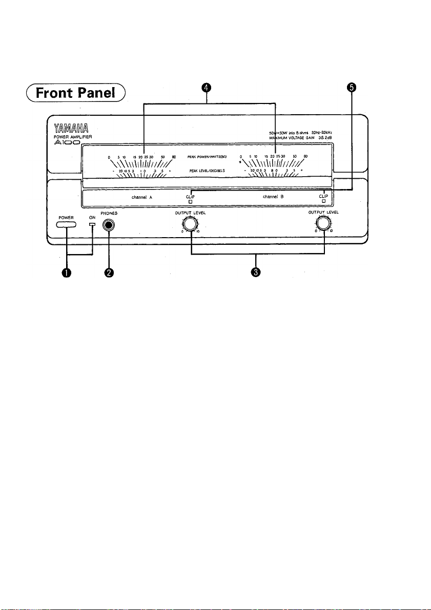
NAMES AND FUNCTIONS OF PARTS
Power switch (POWER) and indicator
When the switch is in the ON position the POWER indicator and level
meter lamp light. No sound is heard from the speakers for a few seconds after
the power is turned on while the protection circuitry is operating.
Headphone jack (PHONES)
e
To monitor amplifier output, plug stereo headphones into this jack. Output to the
speakers is cut off when headphones are plugged into the jack.
* If the MODE switch (on the rear panel) is set to MONO, inverted phase sound
will be heard from headphones plugged into the PHONES jack. Do not use
headphones with the A100 with the MODE switch set to MONO.
Ou^ut level controls (OUTPUT LEVEL)
©
Use*this knobs to adjust the level of the input (output) signal. Turn towards the
"10" indication to increase the level.
* In a monaural (BTL) configuration, the level is controlled using the channel A
knob.
* You can usually leave the knobs in the "10" position and use the mixer or
preamplifier volume control to adjust the volume.
Output level meters
These VU type level meters display the output level. The meters are calibrated to
display both the output wattage with a speaker impedance of 8 Ohm and the
output level in decibels. (OdB shows 25W into 8 Ohm)
In case of MONO-operation both meters show the same output level.
Clipping indicators (CLIP)
0
These indicators light if the input level is excessive or if the speaker impedance
drops too low.
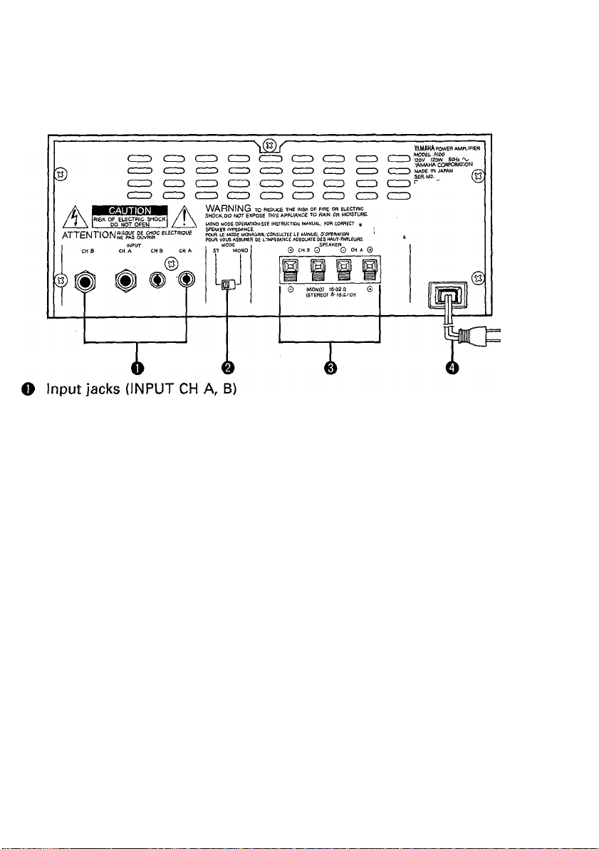
Page 7
POWER AMPLIFIER
AlOO
( Rear Panel )
These jacks are used to connect a mixer or preamplifier to the A100. Connect to
either phone or the pin jacks, as appropriate. If both phone and pin jacks are
connected together, the signal fronh the phone jacks takes precedence.
* In a monaural (BTL) configuration, use the CH A jacks only.
(U.S Model)
e Mode switch (MODE ST/MONO)
Use this switch to select either stereo or monaural operation. The A100 becomes
a monaural power amplifier with a rated output of 10OW (into 16 Ohm) when the
switch is in the MONO position.
Speaker terminals (SPEAKER CH A, B)
e
Connect the speakers to these terminals. When using the A100 as a stereo
power amplifier, connect speakers to both the CH A and CH B terminals. Be
careful not to reverse the polarity (+"), (-) at either the amplifier of speaker end
when making connections. Speakers with a rated impedance between 8 Ohm
and 16 Ohm should be used when the A100 is used as a stereo amplifier. When
using the A100 as a monaural amplifier, connect the speaker's (+) terminal to the
CH A (+) terminal and the (-) terminal to the CH B (+) terminal. Speakers with a
rated impedance between 16 Ohm and 32 Ohm should be used when the A100
is used in a monaural configuration.
To connect the speaker cables, check the polarity (+), (-) once again, then, while
pressing the terminal lever with your finger, insert the exposed conductor portion
of the cable Into the hole in the terminal and release the lever.
O AC power cord
Plug this power cord into an AC outlet. (Power requirements match local AC
voltage and frequency in area where sold.)
6
Page 8
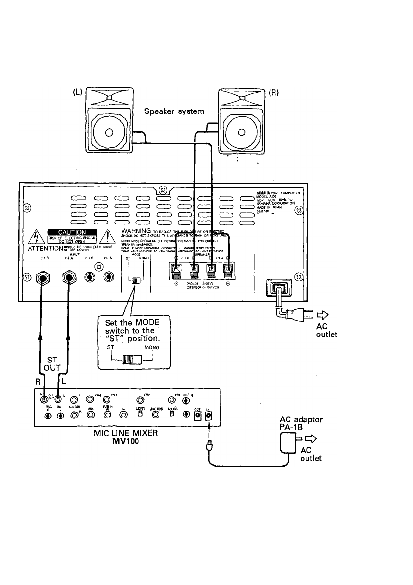
SYSTEM EXAMPLES
1. Stereo connection
S100
S100
Page 9
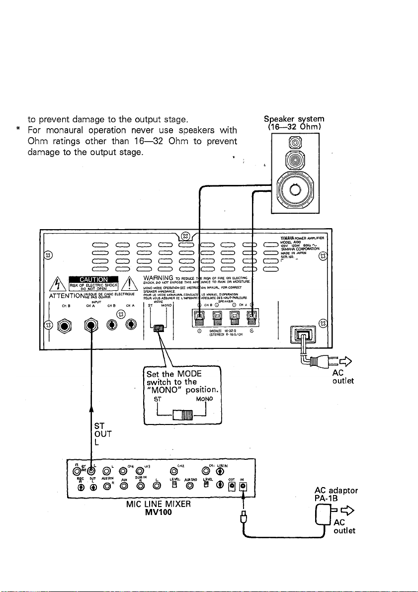
2. Monaural connection
Since the YAMAHA speakers SI 00 are 8 Ohm
speakers never use them for monaural connection.
POWER AMPLIFIER
lOO
8
Page 10
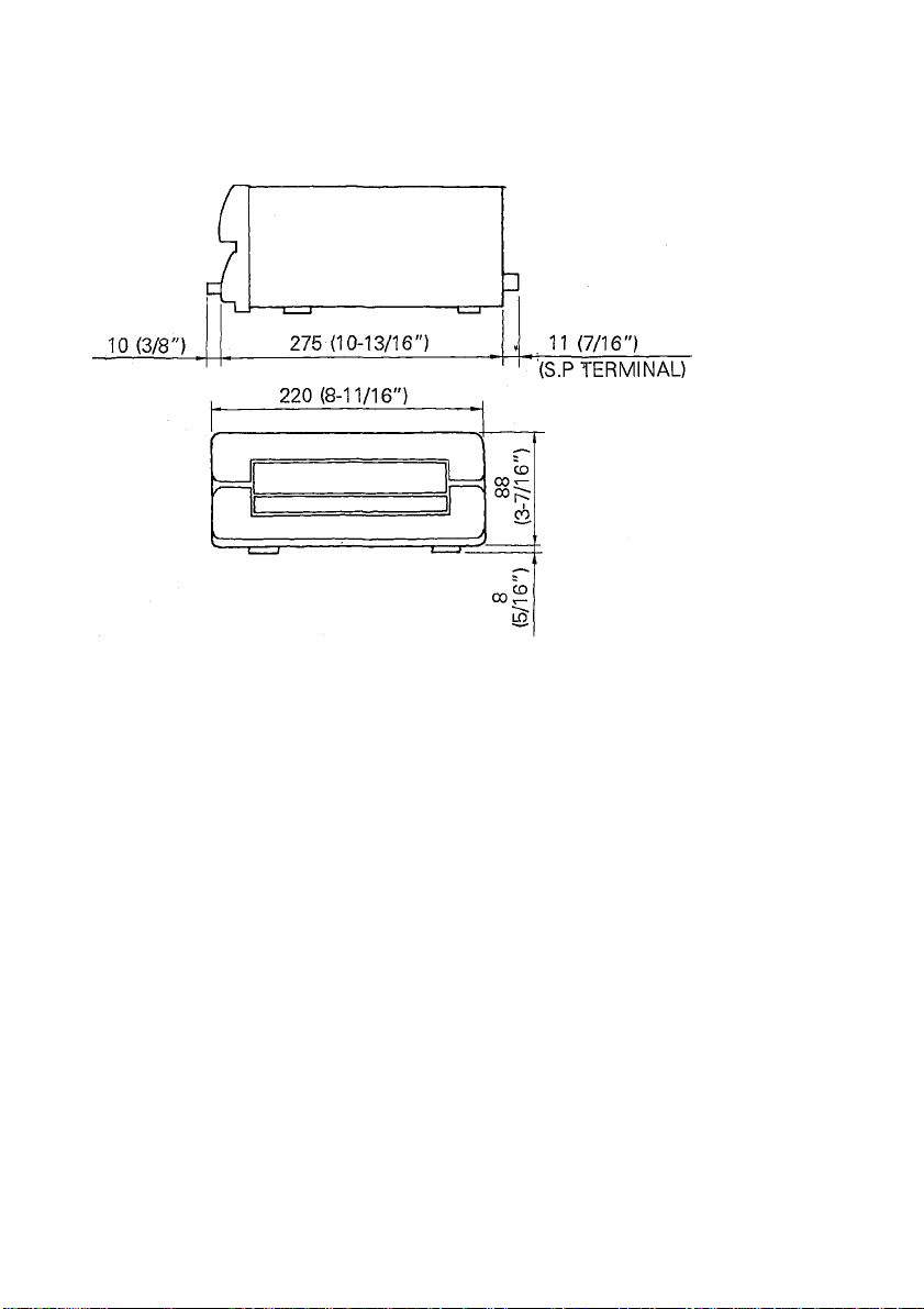
DIMENSIONS
UNIT = mm (inch)
Page 11

BLOCK DIAGRAM
POWER AMPLIFIER
lOO
10
Page 12

IMPORTANT NOTICE FOR THE UNITED KINGDOM
Connecting the Plug and Cord
IMPORTANT. The wires in this mains lead are coloured in accordance with the follow
ing code:
BLUE : NEUTRAL
BROWN : LIVE
As the colours of the wires in the mains lead of this apparatus may not correspond with
the coloured markings identifying the terminals in your plug proceed as follows;
The wire which is coloured BLUE must be connected to the terminal which is marked
with the letter N or coloured BLACK.
The wire which is coloured BROWN must be connected to the terminal which is
marked with the letter L or coloured RED.
Page 13

AMPLIFICATEUR DE PUISSANCE
A'
Manuel d'instructions
en
Page 14

INTRODUCTION
Nous vous remercions d'avoir porté votre choix sur
l'amplificateur de puissance YAMAHA A100. Le A100 est un
amplificateur de puissance de haute qualité pourvu de VUmètres de grandes dimensions. Sa puissance de sortie nomi
nale est de 50 W -1- 50 W (stéréo, sous 8 ohms) ou de 100 W
(connecteur BTL, sous 16 ohms) lorsqu'il est utilisé en mono.
Afin d'obtenir des performances optimales du Al00 et
d'assurer son bon fonctionnement pendant de très nom
breuses années, nous vous conseillons vivement de lire très at
tentivement ce manuel d'instructions avant d'utiliser
l'amplificateur de puissance.
TABLE DES MATIERES
CARACTERISTIQUES PRINCIPALES
PRECAUTIONS
COMMANDES ET PRISES
EXEMPLES DE SYSTEME
SPECIFICATIONS .....................
DIMENSIONS
SCHEMA DE PRINCIPE..................
.......................
................
.................
.........................
13
.......
.........
.........
.
......
......
.........
.........
.........
14
14
15/16
17/18
19
20
21
Page 15

POWER AMPLIFIER
lOO
CARACTERISTIQUES PRINCIPALES
* Puissance de sortie élevée de 50 W + 50 W (stéréo, sous 8 ohms) ou de 100 W
(connecteur BTL, sous 16 ohms),
VU-mètres de grande qualité (avec témoin d'écrêtage).
* Prise PHONES pour l'écoute de contrôle de sortie au moyen d'un casque stéréo.
* Du fait de ses dimensions demi-rack et de son poids réduit, le Al 00 est peu
encombrant et peut se transporter facilement.
PRECAUTIONS
• Eviter d'utiliser l'appareil dans les emplacements suivants afin de prévenir tous
risques d'endommagement ou d'avarie.
* Emplacements exposés aux rayons directs du soleil ou à proximité d'un ap
pareil de chauffage, etc.
* Emplacements où les températures sont extrêmes.
* Emplacements excessivement humides ou poussiéreux.
* Emplacements soumis à de fortes vibrations.
• Ne pas forcer les commandes et les boutons.
• Ne pas ouvrir le coffret et ne pas toucher aux circuits internes car vous risqueriez
d'endommager l'appareil et de recevoir un choc électrique.
• En cas de déplacement de l'amplificateur, veiller à débrancher le cordon
d'alimentation et tous les câbles de raccordement.
• N'utiliser ni benzine, ni diluant, ni solvant pour nettoyer l'appareil et éviter de vapo
riser à proximité des insecticides du type à aérosol (ces produits pourraient tacher
l'appareil, etc.)
• Vérifier que la tension d'alimentation spécifiée sur le panneau arrière correspond à
la tension secteur locale. S'assurer également que l'intensité d'alimentation
secteur est plus que suffisante pour alimenter tous les équipements du système.
• Une fois que vous avez lu ce manuel d'instructions conservez-le en lieu sûr.
14
Page 16

COMMANDES ET PRISES
Interrupteur et témoin d'alimentation (POWER)
Le témoin ON s'allume lorsque l'interrupteur est enclenché (-Mm.). Aucun son ne
parvient des enceintes pendant quelques secondes après la mise sous tension,
pendant que le circuit de protection fonctionne.
Prise de casque d'écoute (PHONES)
©
Permet l'écoute de contrôle des signaux de sortie de l'amplificateur de puis
sance. Les signaux de sortie ne sont pas transmis aux enceintes lorsqu'un
casque d'écoute est branché à cette prise.
* Si le sélecteur MODE (sur la face arrière) est réglé sur MONO, le son capté
par le casque d'écoute branché à la prise PHONES sera déphasé. Ne pas
utiliser de casque d'écoute avec le Al 00 si le sélecteur MODE est réglé sur
MONO.
Boutons de commande du niveau de sortie (OUTPUT LEVEL)
©
Utiliser ces boutons pour régler le niveau du signal d'entrée (sortie). Tourner vers
l'indication "10" pour augmenter le niveau.
* En configuration mono (BTL), le niveau est réglé au moyen du bouton de canal
A.
* En général, il est possible de laisser ces boutons sur la position "10" et
d'utiliser la commande de volume du préamplificateur ou de la table de mixage
pour régler le volume,
O VU-mètres de sortie
Ces VU-mètres indiquent le niveau de sortie. Ils ont été étalonnés pour afficher la
puissance de sortie en watts, avec des enceintes ayant une impédance de 8
ohms, et le niveau de sortie en décibels. (0 dB indique 25W sous 8 ohms) En cas
d'utilisation MONO les deux VU-mètres indiquent le même niveau de sortie.
© Témoins d'écrêtage (CLIP)
Ces témoins s'allument lorsque le niveau d'entrée est excessif.
15
Page 17

lOO
(Face arrière)
(Modèle général)
Prises d'entrée (INPUT CH A, B)
Ces prises sont utilisées pour connecter une table de mixage ou un
préamplificateur au Al 00. Raccorder aux prises jack ou aux prises à broches
selon le cas. Lorsque les prises jack et les prises à broches sont connectées, les
prises jack prévalent.
* En configuration mono (BTL), n'utiliser que les prises CH A.
Sélecteur de mode (MODE ST/MONO)
e
Utiliser ce sélecteur pour sélectionner, soit le fonctionnement en stéréo, soit le
fonctionnement en mono. Lorsque ce sélecteur est mis sur la position MONO, le
Al 00 devient un amplificateur de puissance mono ayant une puissance de sortie
nominale de 100 W (sous 16 ohms).
Bornes d'enceinte (SPEAKER CH A, B)
0
Connecter les enceintes à ces bornes. Lorsque le Al 00 est utilisé comme un
amplificateur de puissance stéréo, connecter aux prises CH A et CH B. Faire
attention de ne pas inverser les polarités (+), (-) aussi bien côté amplificateur que
côté enceintes. Les enceintes doivent avoir une impédance nominale comprise
entre 8 ohms et 16 ohms lorsque le Al 00 est utilisé comme un amplificateur de
puissance stéréo. Lorsque le Al 00 est utilisé comme un amplificateur de puis
sance mono, connecter la borne (+) de l'enceinte à la borne CH A (+) et la borne
(-) à la borne CH B (+). L'enceinte doit avoir une impédance nominale comprise
entre 16 ohms et 32 ohms lorsque le Al 00 est utilisé comme un amplificateur de
puissance mono.
Vérifier la polarité (+), (-) une fois de plus avant de connecter les câbles
d'enceinte, appuyer sur le levier de la borne, introduire la partie dénudée du câble
dans l'orifice de la borne et relâcher le levier.
Cordon d'alimentation secteur
Brancher ce cordon à une prise secteur. (Les caractéristiques d'alimentation cor
respondent à la tension secteur/fréquence de la région où l'appareil a été acheté.)
16
Page 18

EXEMPLES DE SYSTEME
1. Raccordement stéréo
S100 Enceintes acoustiques S100
17
Page 19

2. Raccordement mono * Les enceintes YAMAHA SI 00 étant des enceintes
de 8 Ohms, ne jamais les utiliser pour le raccorde
ment mono afin de ne pas endommager l'étage de
POWER AMPLIFIER
Enceinte acoustique
(16—32 ohms)
lOO
Page 20

SPECIFICATIONS
Prises d'entrée:
Connecteur de sortie:
Fonctions:
Sortie nominane:
Sensibilité d'entrée:
Gain de tension:
Réponse en fréquence:
Largeur de bande de puissance
Distorsion Harmonique Totale:
Distorsion d'intermodulation:
Séparation entre canaux:
Rapport signal/bruit:
Bruit résiduel:
Taux de balayage:
Coefficient d'affaiblissement:
Impédance d'entrée:
Alimentation:
Consommation:
Dimensions (L x H x P):
Poids:
Accessories standards:
Prise à broche x 1/canal, prise jack x 1/canal
Bornes-poussoir 4P
Interrupteur POWER, Commandes OUTPUT LEVEL,
VU-mètres, Témoins CLIP,
Sélecteur de MODE (ST/MONO)
50 W + 50 W (stéréo, DHT 1 %, 8 ohms)
100 W (BTL mono, DHT 1%, 16 ohms)
-10 dB (245 mV), (1 kHz, 50 W/8 ohms, vol. maxi.)
38,2 dB (1 kHz, entrée -10 dB)
20 Hz — 20 kHz (0 ± 0,5 dB)
10 Hz — 50 kHz (DHT 0,2%, 25 W, 8 ohms)
0,02% (1 kHz, 25 W/8 ohms, stéréo)
0.2% (20 Hz — 20 kHz, 25W/8 ohms, stéréo)
0.2% (70 Hz : 7 kHz = 4 : 1, 25W/8 ohms, stéréo)
70 dB (1 kHz), 60 dB (20 Hz — 10 kHz)
105 dB (entrée en court-circuit, IHF A)
-77 dB (vol. mini., IHF A)
10 V/1 psec. (cycle total, 8 ohms, stéréo)
Plus de 70 (1 kHz/8 ohms), plus de 60 (20 Hz — 20
kHz, 8 ohms)
Plus de 7,5 kohms
Modèle pour les Etats-Unis:Secteur de 120 V, 60 Hz
Modèle générahSecteur de 220 à 240 V, 50 à 60 Hz
Modèle pour les Etats-Unis: 120 W
Modèle général:120 W
220 X 96 X 296 mm
4,6 kg
Manuel d'instructions
0 dB = 0,775 Veff.
Les spécifications et le design sont susceptibles d'être modifiés sans autre forme
d'avis.
19
Page 21

DIMENSIONS
POWER AMPLIFIER
JOO
20
Page 22

SCHEMA DE PRINCIPE
INPUT(-IOdB) °l^evel^
SPEAKERS
21
Page 23

LEISTUNGSVERSTARKER
Bedienungsanleitung
Deutsch
Page 24

EINLEITUNG
Herzlichen Dank für den Kauf des YAMAHA Leistungs
verstärkers A100. Beim A100 handelt es sich um einen
hochwertigen Verstärker mit einer Ausgangsleistung von 50W
+ 50W (Stereo bei 8 Ohm Last), dessen großzügig dimensio
nierte VU-Meter einen genauen Pegelabgleich erlauben. Bei
Verwendung in einer Mono-Anordnung (überbrückter An
schluß, 16 Ohm Last) erbringt der A100 100 Watt.
Um das volle Potential Ihres A100 ausschöpfen zu können und
eine lange Lebensdauer zu gewährleisten, sollten Sie diese Be
dienungsanleitung vor der Inbetriebnahme gründlich durch
lesen.
INHALT
MERKMALE.............................................................................
VORSICHTSMASSNAHMEN
BEDIENELEMENTE UND ANSCHLÜSSE
SYSTEMBEISPIELE
TECHNISCHE DATEN ..........................................................
ABMESSUNGEN.....................................................................
BLOCKDIAGRAMM
........
...............................................................
.........................
.........................
......................................................
23
..................
..
..................
...........25/26
...........27/28
..................
..................
..................
24
24
29
30
30
Page 25

POWER AMPLIFIER
AlOO
MERKMALE
• Hohe Ausgangsleistung von 50 W + 50 W (Stereobetrieb, 8 Ohm Last) bzw. 100
W (Monobetrieb, 16 Ohm Last).
• Hochwertige VU-Pegelmesser mit Verzerrungsanzeigen.
• PHONES-Buchse erlaubt Klangüberwachung mit Stereokopfhörern.
• Dank des kompakten leichten Designs beansprucht der AI 00 nur die Hälfte des
Einbauplatzes in einem DIN-Audiorack und kann leicht transportiert werden.
VORSICHTSMASSNAHMEN
• Das Gerät keinesfalls an folgenden Orten aufstellen;
* Orte mit direkter Sonneneinstrahlung, oder in der Nähe von Heizgeräten usw.
* Orte, an denen extreme Temperaturen auftreten.
* Orte mit extremer Feuchtigkeit oder übermäßigem Staubanfall.
* Orte, an denen starke Vibrationen auftreten.
• Schalter und Knöpfe keinesfalls mit Gewalt handhaben.
• Keinesfalls das Gehäuse öffnen oder interne Schaltungen verändern. Dies bewirkt
Gefahr von elektrischen Schlägen oder Schäden am Gerät.
• Beim Ändern des Aufstellorts zunächst das Netzkabel des Verstärkers sowie die
Anschlußkabel abklemmen.
• Das Gerät keinesfalls mit Benzin, Verdünnern oder Lösungsmitteln reinigen. Kein
Insektenspray in der Nähe des Geräts versprühen. Diese Substanzen greifen die
Gehäuseoberfläche an!
• Sicherstellen, daß die örtliche Netzspannung den auf der Rückseite aufgeführten
Betriebsspannungswerten des AI 00 entspricht. Ebenso darauf achten, daß die
Netzsteckdose die Leistungsaufnahme des AI 00 verkraftet.
• Diese Bedienungsanleitung an einem sicheren Ort aufbewahren.
24
Page 26

BEDIENELEMENTE UND ANSCHLÜSSE
O Netzschalter (POWER) und -anzeige
Dient zum Ein- und Ausschalten des AI 00. Bei eingeschaltetem AI 00 leuchtet
die POWER-Anzeige auf. Da die Schutzschaltung nach dem Einschalten einige
Sekunden lang arbeitet, ist der AI 00 vorübergehend stummgeschaltet.
Kopfhörerbuchse (PHONES)
Zum Mithören kann ein Stereokopfhörer an diese Buchse angechlossen werden.
Bei angeschlossenem, Kopfhörer sind die Lautsprecherausgänge stummgeschal
tet.
* Falls der MODE-Schalter auf der Rückseite auf MONO gestellt ist, gibt die
PHONES-Buchse die Signale mit umgekehrter Phase ab. Bei MONO-Betrieb
keinen Kopfhörer anschließen.
Ausgangspegelregler (OUTPUT LEVEL)
Über diese Regler den Ein/Ausgangspegel einstellen. Zum Erhöhen des Pegels
die Regler in Richtung "10" drehen.
* Bei Mono-Betrieb (Brückenschaltung) wird der Pegel über den Regler für Kanal
A (CH A) eingestellt.
* Normalerweise sollten diese Regler auf "10" gestellt und die Lautstärke über
die Regler des Vorverstärkers oder Mischpults justiert werden.
O Ausgangspegelmesser
Diese VU-Messer geben den Ausgangspegel an. Diese VU-Messer sind auf An
zeige der Ausgangsleistung in Watt für eine Last von 8 Ohm ausgelegt und
geben den Ausgangspegel auch in Dezibel bei 8 Ohm Last an. (OdB entsprechen
25W bei 8 Ohm Last).
Bei MONO-Betrieb zeigen beide Peglmesser den gleichen Ausgangspegel an.
O Verzerrungsanzeige (CLIP)
Diese Anzeige leuchtet bei zu hohem Eingangspegel oder zu stark abfallender
Lautsprecherimpedanz auf.
25
Page 27

oo
( Rückseite )
Diese Buchsen dienen zum Anschluß eines Vorverstärkers oder Mischpults. Es
stehen zwei Anschlußtypen zur Wahl: Klinkensteckerbuchsen und Cinchbuchsen,
wobei die Klinkensteckerbuchsen Vorrang haben.
* Für Mono-Betrieb nur die Buchsen CH A zum Anschluß verwenden.
0
Betriebsartschalter (MODE ST/MONO)
Dieser Schalter dient zur Wahl zwischen Stereo- und Mono-Betrieb. In der
MONO-Stellung arbeitet der AI00 als Mono-Verstärker mit einer Ausgangslei
stung von 100 W (bei einer Last von 16 Ohm).
Lautsprecherklemmen (SPEAKER CH A, B)
0
Wenn der AI 00 als Stereo-Leistungsverstärker eingesetzt werden soll, die Laut
sprecher an beide Klemmenpaare (CH A und B) anschließen. Dabei nicht die
Polarität (-I-), (-) auf der Lautsprecher- oder Verstärkerseite vertauschen. Bei Ein
satz als Stereo-Verstärker muß die Lautsprecherimpedanz 8 Ohm bis 16 Ohm
betragen. Wenn der AI 00 als Mono-Verstärker verwendet werden soll, die posi
tive (-I-) Klemme des Lautsprechers mit der positiven {+) Klemme von CH A ver
binden und die negative (-) Klemme des Lautsprechers an die positive (-i-)
Klemme von CH B anschließen. Für Mono-Betrieb müssen Lautsprecher mit
einer Impedanz von 16 Ohm bis 32 Ohm eingesetzt werden, um eine Überla
stung der Endstufe zu verhindern.
Vor dem Anschließen der Lautsprecherkabel erneut die Polarität (+), (-)
überprüfen. Dann den Klemmenhebel hinunterdrücken, das freigelegte Draht
ende des Kabels in das Klemmenloch einführen und den Hebel loslassen.
(Allgemeines Modell)
O Netzkabel
Dieses kabel an eine Steckdose anschließen (Die Betriebsspannung ist bereits ab
Werk auf das Bestimmungsland eingestellt).
26
Page 28

SYSTEMBEISPIELE
1. Stereo-System
SI 00
S100
27
Page 29

2. Mono-System * Da die YAMAHA Lautsprecher S100 eine Ein-
3n, dürfen
POWER AMPLIFIER
lOO
Page 30

TECHNISCHE DATEN
Eingänge:
Ausgänge:
Funktionen:
Nennausgangsleistung:
Eingangsempfindlichkeit:
Verstärkungsfaktor:
Frequenzgang:
Leistungssignalbandbreite:
Gesamtklirrfaktor:
Intermodulationsverzerrung
Kanaltrennung:
Rauschabstand:
Restrauschen:
Anstiegsgeschwindigkeit:
Dämpfungsfaktor:
Eingangsimpedanz:
Stromversorgung:
Leistungsaufnahme:
Abmessungen (B x H x T):
Gewicht:
Zubehör:
Cinchbuchsen x 1/K, Klinkenbuchsen x 1/K
4 gepolte Lautsprecherklemmen
POWER-Schalter, OUTPUT LEVEL-Regler,
Pegelanzeigen, CLIP-Anzeigen
50 W + 50 W (Stereo, Gesamtklirrfaktor 1%, 8 Ohm
Last)
100W (MonO-Brücke, Gesamtklirrfaktor 1%, 16 Ohm
Last) .
-10 dB (245mV), (1 kHz, BOW/S Ohm, max. Lautstärke)
38,2 dB (1 kHz, Eingangspegel -lOdB)
20 Hz — 20 kHz (0 ± 0,5 dB)
10 Hz — 50 kHz (Gesamtklirrfaktor 0,2%, 25 W Ausgang,
8 Ohm Last)
0,02% (1 kHz, 25 W/8 Ohm, Stereo)
0,2% (20 Hz — 20 kHz, 25 W/8 Ohm, Stereo)
0,2% (70 Hz : 7 kHz = 4 : 1, 25W/8 Ohm, Stereo)
70 dB (1 kHz), 60 dB (20 Hz — 10 kHz)
105 dB (Eingang kurzgeschlossen, Betriebsklasse A
bewertet)
-77dB (Min. Lautstärke, Betriebsklasse A bewertet)
10 V/psec, (volle Schwingung, 8 Ohm, Stereo)
Über 70 (1 kHz/8 Ohm), über 60 (20 Hz ■— 20 kHz, 8
Ohm)
Über 7,5 kOhm
USA Modell: 120V, 60Hz
Allgemeines Modell: 220 bis 240V, 50 bis 60 Hz
USA Modell: 120 W
Allgemeines Modell: 120 W
220 X 96 X 296 mm
4,6 kg
Bedienungsanleitung
OdB = 0,775 Veff
Das Recht zu Änderungen an Daten und Design ohne Vorankündigung bleibt
Vorbehalten.
29
Page 31

ABMESSUNGEN
BLOCKDIAGRAMM
POWER AMPLIFIER
lOO
30
Page 32

ACCESSORIES/ACCESSOIRES/ACCESSOIRES
• Rack Mount Kit / RK100, RK200
• Kits de montage en rack / RK100, RK200
• Rack-Einbausatz / RK100, RK200
• These provide space for 19" rack mounting of YAMAHA #100 series units.
• Cas Kits permettent le montage en rack de 19" d'appareils YAMAHA de la série
100.
• Dienen zum Einbau von YAMAHA-Geräten der Sérié 100* in 19 zoll Racks.
RK100 (lU-Type / Type 1U / Typ 1U)
n-
RK200 (2U-Type / Type 2U / Typ 2U)
r
,
2U
ILs
_________________
• Joint Metal / JK100
• Fixation / JK100
• Verbindungsstück / JK100
JK100
• An accessory for setting up YAMAHA
#100 series units.
• Un accessoire servant à installer
plusieurs appareils YAMAHA de la
série 100.
• Zubehör zum Aufeinanderstapeln von
mehreren YAMAHA-Geräten der Serie
100.
YAMAHA
YAMAHA CORPORATION
PO.Box 1, Hamamatsu, Japan
8904 R2 El @ Printed in Japan
 Loading...