

Yamaha 10-FLXUC1500, 10-FLXUC1000 Installation And Operation Manual

1
™
REVOLABS FLX UC 1000
™
REVOLABS FLX UC 1500
IP & USB Conference Phone
&
Installation and Operation Guide
Models:
10-FLXUC1000
10-FLXUC1500

2
© 2018 Yamaha UC, Inc. All rights reserved. No part of this document may
be reproduced in any form or by any means without express written
permission from Yamaha UC, Inc. Product specifications are subject to
change without notice.
Revolabs FLX UC 1000 & Re volabs FL X UC 1500
Installation and Operation Guide
SEPTEMBER 2018 (Rev 2.1.0)

3
Contents
Contents ...................................................................................................................... 3
Getting Started with the FLX UC 1000 ......................................................................... 5
Assembling the FLX UC 1000 ................................................................................... 5
Connecting the Dialer ............................................................................................ 6
Powering up the FLX UC 1000 ............................................................................... 8
Connecting the FLX UC 1000 to a Computer ......................................................... 9
Understanding the Components of the FLX UC 1000 .............................................. 10
Base Unit ............................................................................................................ 10
Dialer .................................................................................................................. 11
User Interface ......................................................................................................... 14
Base Unit ............................................................................................................ 14
Dialer .................................................................................................................. 14
Web User Interface (Web UI) ................................................................................ 20
Basic Operations ....................................................................................................... 25
Dialing a Number ................................................................................................... 25
Redialing a Number ................................................................................................ 25
Dialing a Contact .................................................................................................... 25
Making a call while another call is already active .................................................... 26
Answering an Incoming Call ................................................................................... 26
Ignoring an Incoming Call ....................................................................................... 26
Hanging Up a Call .................................................................................................. 26
Using USB Audio on the FLX UC 1000 ................................................................... 26
Setting up a Conference Call .................................................................................. 27
Using Do Not Disturb ............................................................................................. 27
Configuring the FLX UC 1000 for your VoIP Network ................................................. 28
Through the Dialer ................................................................................................. 28
Through Web User Interface ................................................................................... 28
Through Provisioning Server, using Option 66 ........................................................ 29
Provisioning configuration file sample ..................................................................... 30
FLX UC 1000 Device Manager ................................................................................... 33
Third Party Applications Supported ........................................................................ 33

4
Installation & Third Party Application Configuration .............................................. 33
For Windows ....................................................................................................... 33
For Mac ............................................................................................................... 34
Upgrading the FLX UC 1000 Device Firmware ........................................................... 35
From the Web Interface .......................................................................................... 35
From the Provisioning Server .................................................................................. 35
Compliance ................................................................................................................ 36
FCC Notice to Users ................................................................................................ 36
Radio and Television Interference ........................................................................... 36
Industry Canada Notice to Users ............................................................................ 37
Notice to European Customers ............................................................................... 37
WEEE Notification .................................................................................................. 38
Appendix ................................................................................................................... 39
Known Issues ......................................................................................................... 39
Optimal Audio Performance for Windows ................................................................ 40
Troubleshooting ...................................................................................................... 41
Reboot ................................................................................................................. 41
Restore Factory Defaults ..................................................................................... 41
Cannot Access Web User Interface ...................................................................... 41
Can’t find language menu because the device is in the wrong language ............... 42
USB Audio call Answering and Hang-Up not working .......................................... 42
Tested Call Managers ................................................................................................. 43
Specific Call Manager Configuration .......................................................................... 44
3CX Phone System ................................................................................................. 44
Digium Asterisk BE ................................................................................................ 44
Avaya IP Office ........................................................................................................ 44
Broadsoft Broadworks ............................................................................................ 45
Cisco Unified Communication Manager .................................................................. 45
Junction Networks OnSip Hosted PBX ................................................................... 45
5
Getting Started with the FLX UC 1000
Assembling the FLX UC 1000
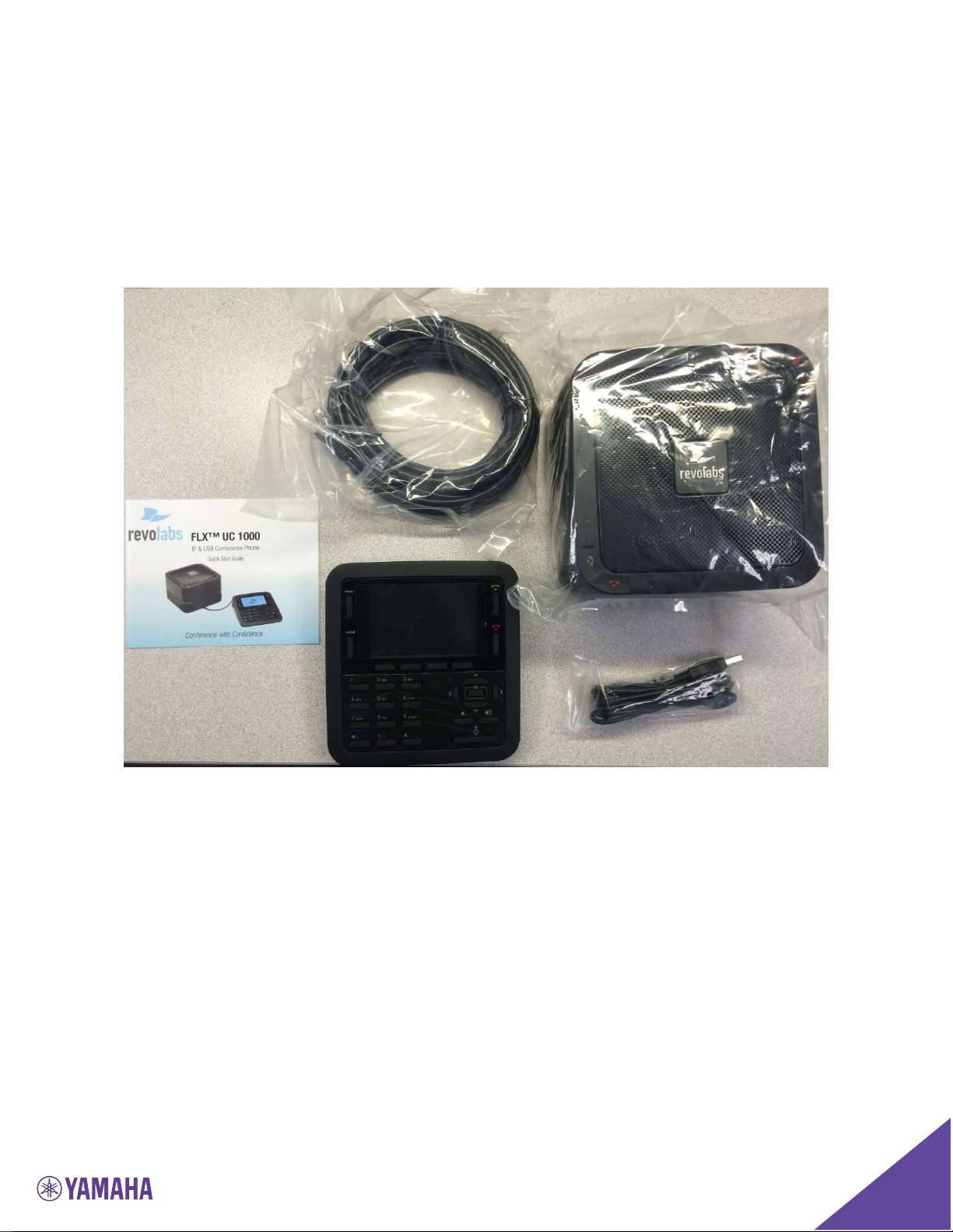
The box of the FLX UC 1000 includes 1 Base Unit, 1 Dialer with connected
cable, 1 Ethernet Cable, and 1 USB cable. Remove all these items from the
packaging.
6
Connecting the Dialer
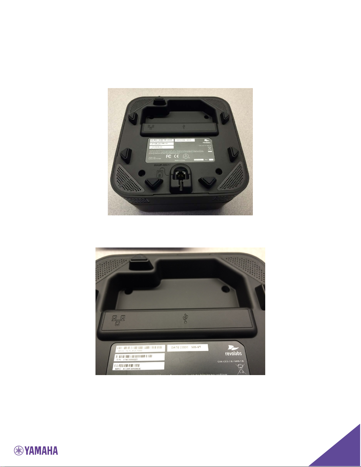
Once the components are removed from the packaging, turn the base unit
upside down. On the bottom of the base unit, there are two areas where you
can connect cables to the base unit.
The area pictured in the figure below is where the USB and Ethernet cables are
connected.
7
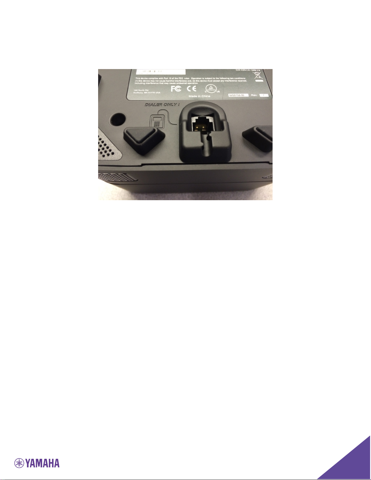
The area pictured in the figure below is the port for the dialer cable labeled
“Dialer Only.”
Take the dialer cable and push that cable connector into the “Dialer Only” hole
until it clicks into place.
8
Powering up the FLX UC 1000
The FLX UC 1000 is designed to be powered using Power over Ethernet (PoE).
If you have an Ethernet port that does not provide PoE, an adapter can be
ordered to provide the device with power.
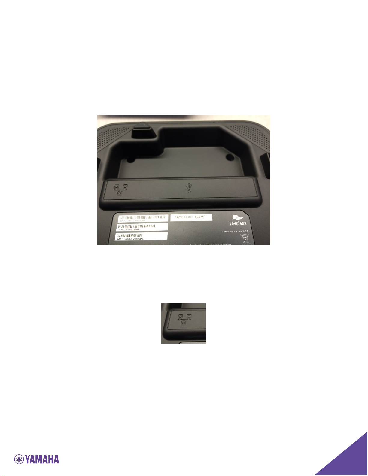
Take the Ethernet cable that was provided in the box, and turn the base unit
upside down, and locate the area displayed below.
Connect one end of the Ethernet cable into the network connection port on the
bottom of the unit. It’s characterized by the icon displayed below. Press until
it clicks into place.
Connect the other end of the Ethernet cable into a jack providing PoE or a PoE
adapter.
If the cable needs to be removed from the FLX UC 1000, depress the plastic
lever on the connection to the FLX UC 1000 and pull the cable out gently while
keeping that plastic lever depressed. Using force when removing this cable
may damage the cable and render it useless.

9
Once connected to a power source, the device will boot up. The lights on the
Base will alternate red-orange-green-orange as the system boots. When it is
ready to use, the Base will chime and the Dialer will bring up the home screen.
Connecting the FLX UC 1000 to a Computer
Using the USB cable that came with the device, connect the mini USB side of
the cable into the connector identified by the icon in the figure below.
Connect the other end of the cable to the USB port on the computer that will be
used with the FLX UC 1000 for third party softphone, webinar, or conferencing
applications.
The computer may detect new driver software and install it, wait until the
install has succeeded before continuing. Once this is complete, a white USB
symbol should appear in the quick-reference bar at the top of the dialer screen.
For optimal audio performance when using Windows, please follow the
instructions in the appendix section.
10
Understanding the Components of the FLX UC 1000
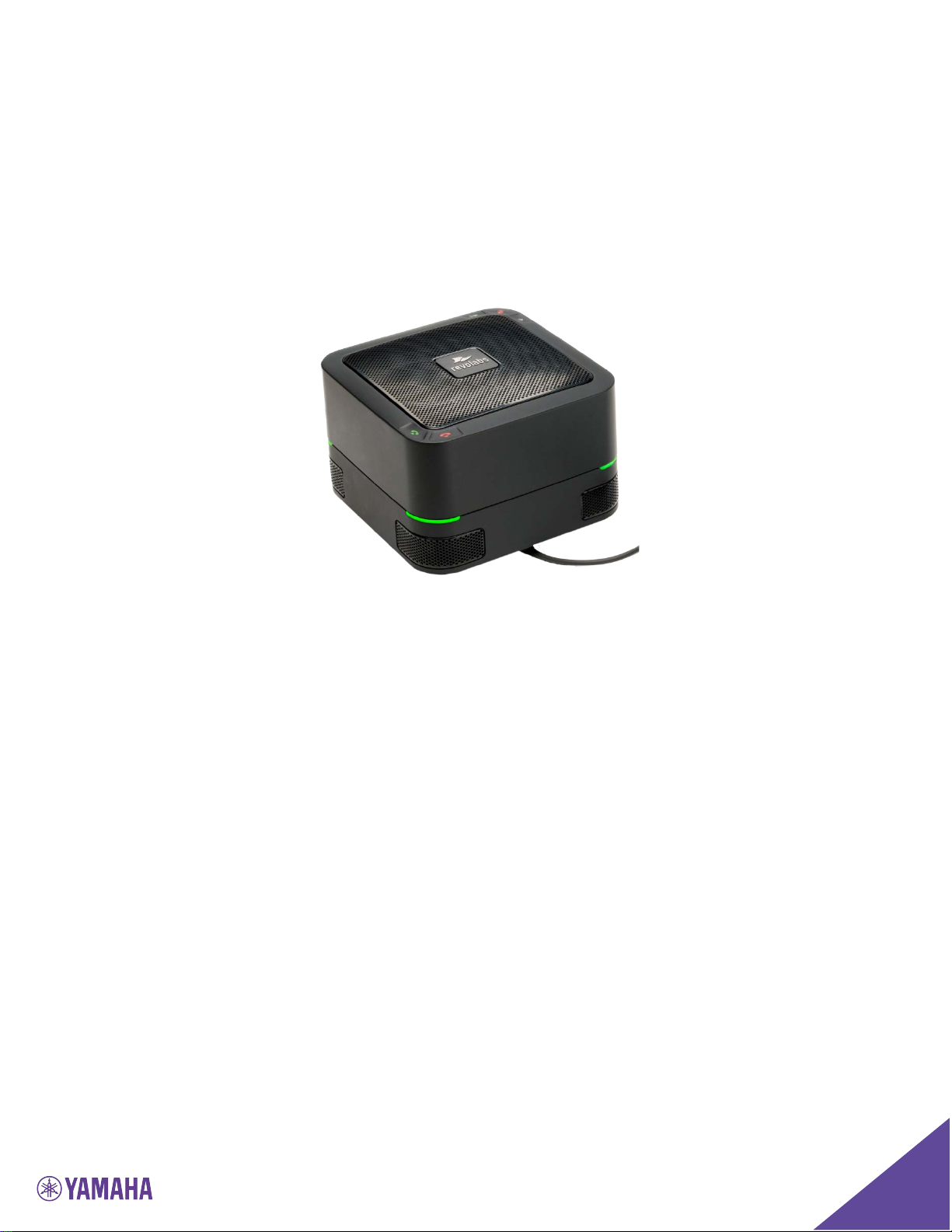
Base Unit
The base unit houses the speaker and 4 embedded microphones of the system.
It includes volume up, volume down, mute, answer call, and hang-up buttons.
On four corners of the base system, there are LEDs to display the call status.
During a call, these LEDs will be green when the system is unmuted and red
when the system is muted.
When not in a call, the lights can be configured for an idle color with options of
solid amber, solid green, or unlit. By default, the idle color will be selected as
unlit. .
On the bottom of the base unit, there are three ports for connecting up the
system: a port for the dialer cable, a port for the USB cable, and a port for the
Ethernet cable.
11
Dialer
There are four categories of buttons on the dialer:
• Quick Keys: Menu, Redial, Answer, Hang Up
• Soft Keys: 4 keys under the color display
• Keypad: Numbers, Letters, Special Characters on Left Side
• Directional Buttons & Volume Control: Located on the Right Side
Quick Keys
The Menu button brings up the Menu interface. While in any menu, pressing
the “menu” button will bring you back to the home screen.
The Redial button opens the recent calls menu.
The green Answer Call Button answers an incoming call and can also be used
to open the dialer menu.
The red Hang-Up Call Button can be used to hang up or end an existing call.

12
Soft Keys
There are four selection buttons under the color screen that correspond to the
options displayed just above the buttons on the screen. These soft keys are
used to navigate menu options. Each button corresponds to the grey box on
the screen right above it. If there is no grey box above the button, that button
does not correspond to anything in the current menu
The Soft Keys provide different options depending on the current screen. The
details of the options provided are provided in the respective screens.
If there are more than 3 soft keys available for the screen, a [MORE>] button
will be displayed for the right most soft key. The user can navigate to the next
set of options by pressing this button. If on the second set of options a
[<MORE] button will be displayed on the left most soft key.
Keypad
The keypad has the digits 0-9, *, and #, and can be used to render the alphabet
in certain menus.
When entering contact names, and the use of letters are required, the keypad
can be used for this. The first time the key is pressed it will type a lowercased
version of the first letter next to that number. Pressing again quickly will
change that letter to the next letter and so on. The first cycle through the
letters that number can type will be lowercase, then the number, then the
same letters uppercase, then repeated again from the beginning.
For example, the number “2” is also responsible for the letters a, b, and c. So, pressed quickly it would
cycle through like this:
a b c 2 A B C a b c 2 A B C
And so on.
Unlike the rest of the number keys, the number “1” only types itself. And
unlike all the other keys, the * key has more than what is shown above the
button that it cycles through. It cycles through:
* . , - _ ( ) @ and then repeats
Directional Buttons & Volume Control
The directional keys are left, right, up, down, and “ok” for selecting.
Generally, The up and down arrow keys can be used to select different
submenu options. The right arrow key can be used to open menus and the left
arrow key can be used to go back.

13
The “OK” and [Select] buttons can be used to enter menus or toggle
configuration items, and the [Back] button can be used to exit menus.
When editing a configuration item that uses a slider bar, the left and right
arrow keys are used to change the value in the slider.
Located near the directional keys are the volume control and mute buttons.
Similar to the base, the system volume can be increased or decreased using the
volume up and volume buttons, and the system can be muted using the mute
button on the dialer.
The mute/unmute button only applies during an active call. It is not applied
to the device when a call is not active.

14
User Interface
Base Unit
As mentioned in the Getting Started section, the base unit provides volume up,
volume down, mute, answer call, and hang-up buttons. Mute status will be
reflected on the LEDs on the four corners of the device; during a call, these
LEDs will be green when the system is unmuted and red when the system is
muted.
When not in a call, the lights can be configured for an idle color with options of
solid amber, solid green, or unlit. By default, the idle color will be selected as
unlit. In order to change this color, an administrator can log into the web UI
and configure the desired idle color.
For additional call control functionality i.e. hang up and answer from the
device for the preferred third party softphone, webinar, or conferencing
application, refer to section in this manual on FLX UC Device Manager.
Dialer
As mentioned in the Getting Started section of the manual, there are a series of
screens on the dialer. The details of those screens are indicated in this section.
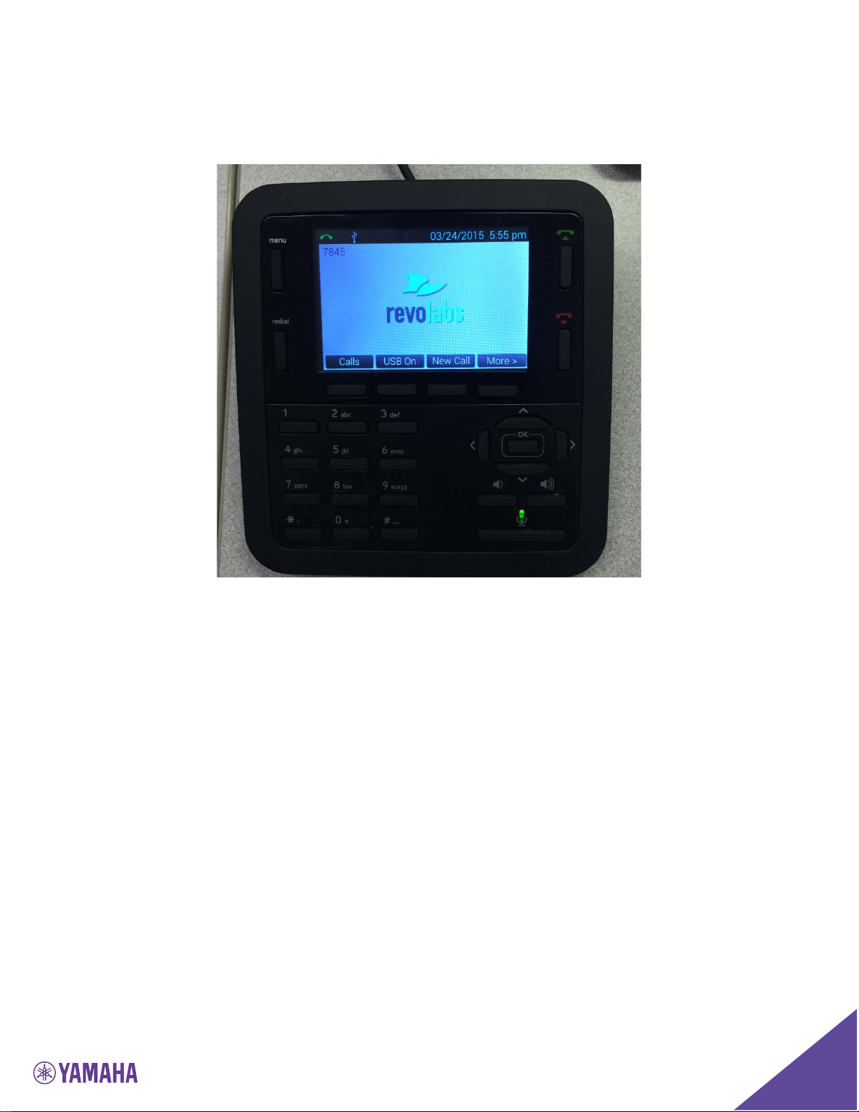
Home Screen
When the device is powered on, the device will display the home screen. This
screen is characterized by the Revolabs Logo (or customer specific logo) in the
center of the screen. On the home screen, there are three key areas to note: a
quick reference bar, information about the user ID of the device, and soft keys.
The quick reference bar provides information of the call status of the system.
The information available in this quick reference bar includes:
• Call Icon (in Green): Displays information about call status including No
Call, Call in Progress, and Mute Indicator
• USB Icon: Displays when the FLX UC 1000 is plugged into a computer
• Do Not Disturb (DND): Displays when the system is configured for do not
disturb.
• Voice Mail Icon: Displays when a voice mail is available
• Missed Call: Displays when a call has been missed
• Date: Displays current date. The format is configurable in the Menu or
Web Interface
 Loading...