

Yamaha 02R96 Owner’s Manual
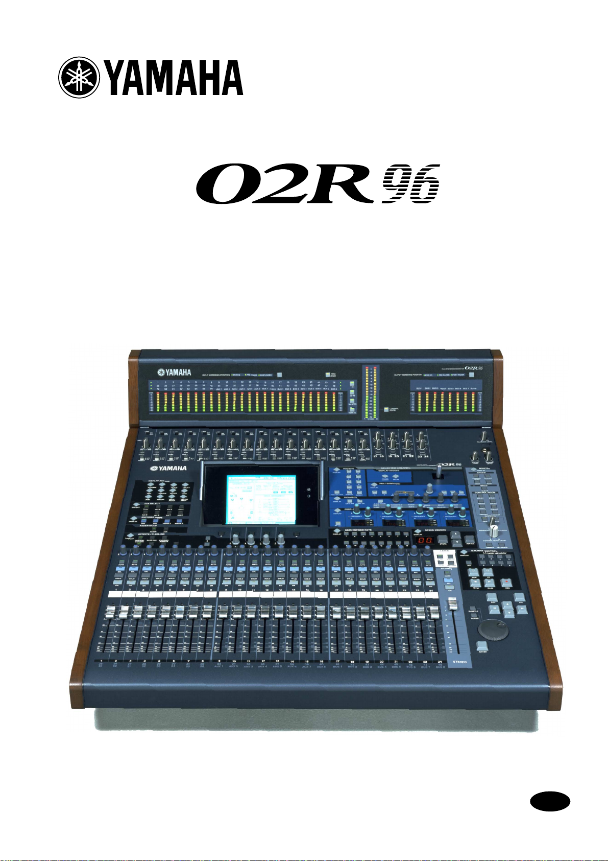
DIGITAL MIXING CONSOLE
Owner’s ManualOwner’s Manual
Owner’s Manual
Keep This Manual For Future Reference.
E

FCC INFORMATION (U.S.A.)
1. IMPORTANT NOTICE: DO NOT MODIFY THIS UNIT! This product, when installed as indicated in the instructions contained in this manual, meets FCC
requirements. Modifications not expressly approved by Yamaha may void your authority, granted by the FCC, to use the product.
2. IMPORTANT: When connecting this product to accessories and/or another product use only high quality shielded cables. Cable/s supplied with this product MUST
be used. Follow all installation instructions. Failure to follow instructions could void your FCC authorization to use this product in the USA.
3. NOTE: This product has been tested and found to comply with the requirements listed in FCC Regulations, Part 15 for Class “B” digital devices. Compliance with
these requirements provides a reasonable level of assurance that your use of this product in a residential environment will not result in harmful interference with
other electronic devices. This equipment generates/uses radio frequencies and, if not installed and used according to the instructions found in the users manual, may
cause interference harmful to the operation of other electronic devices. Compliance with FCC regulations does not guarantee that interference will not occur in all
installations. If this product is found to be the source of interference, which can be determined by turning the unit “OFF” and “ON”, please try to eliminate the
problem by using one of the following measures: Relocate either this product or the device that is being affected by the interference. Utilize power outlets that are on
different branch (circuit breaker or fuse) circuits or install AC line filter/s. In the case of radio or TV interference, relocate/reorient the antenna. If the antenna lead-in
is 300 ohm ribbon lead, change the lead-in to coaxial type cable. If these corrective measures do not produce satisfactory results, please contact the local retailer
authorized to distribute this type of product. If you can not locate the appropriate retailer, please contact Yamaha Corporation of America, Electronic Service
Division, 6600 Orangethorpe Ave, Buena Park, CA 90620
The above statements apply ONLY to those products distributed by Yamaha Corporation of America or its subsidiaries.
WARNING: THIS APPARATUS MUST BE EARTHED
IMPORTANT
THE WIRES IN THIS MAINS LEAD ARE COLOURED IN
ACCORDANCE WITH THE FOLLOWING CODE:
GREEN-AND-YELLOW : EARTH
BLUE : NEUTRAL
BROWN : LIVE
As the colours of the wires in the mains lead of this apparatus may
not correspond with the coloured markings identifying the terminals in
your plug, proceed as follows:
The wire which is coloured GREEN and YELLOW must be
connected to the terminal in the plug which is marked by the letter E
or by the safety earth symbol or coloured GREEN and YELLOW.
The wire which is coloured BLUE must be connected to the terminal
which is marked with the letter N or coloured BLACK.
The wire which is coloured BROWN must be connected to the
terminal which is marked with the letter L or coloured RED.
* This applies only to products distributed by YAMAHA KEMBLE
MUSIC (U.K.) LTD.
NEDERLAND THE NETHERLANDS
● Dit apparaat bevat een lithium batterij voor geheugen
back-up.
ADVARSEL!
Lithiumbatteri—Eksplosionsfare ved fejlagtig
håndtering. Udskiftning må kun ske med batteri
af samme fabrikat og type. Levér det brugte
batteri tilbage til leverandoren.
VARNING
Explosionsfara vid felaktigt batteribyte. Använd
samma batterityp eller en ekvivalent typ som
rekommenderas av apparattillverkaren.
Kassera använt batteri enligt fabrikantens
instruktion.
VAROITUS
Paristo voi räjähtää, jos se on virheellisesti
asennettu. Vaihda paristo ainoastaan
laitevalmistajan suosittelemaan tyyppiin. Hävitä
käytetty paristo valmistajan ohjeiden
mukaisesti.
● This apparatus contains a lithium battery for memory
back-up.
● Raadpleeg uw leverancier over de verwijdering van de
batterij op het moment dat u het apparaat ann het einde
van de levensduur afdankt of de volgende Yamaha Service
Afdeiing:
Yamaha Music Nederland Service Afdeiing
Kanaalweg 18-G, 3526 KL UTRECHT
Tel. 030-2828425
● Gooi de batterij niet weg, maar lever hem in als KCA.
CAUTION
RISK OF ELECTRIC SHOCK
DO NOT OPEN
CAUTION: TO REDUCE THE RISK OF
ELECTRIC SHOCK, DO NOT REMOVE
COVER (OR BACK). NO USER-SERVICEABLE
PARTS INSIDE. REFER SERVICING TO
QUALIFIED SERVICE PERSONNEL.
The above warning is located on the
side of the unit.
● For the removal of the battery at the moment of the
disposal at the end of the service life please consult your
retailer or Yamaha Service Center as follows:
Yamaha Music Nederland Service Center
Address: Kanaalweg 18-G, 3526 KL
UTRECHT
Tel: 030-2828425
● Do not throw away the battery. Instead, hand it in as small
chemical waste.
• Explanation of Graphical Symbols
The lightning flash with arrowhead symbol
within an equilateral triangle is intended to
alert the user to the presence of uninsulated
“dangerous voltage” within the product’s
enclosure that may be of sufficient magnitude to constitute a risk of electric shock to
persons.
The exclamation point within an equilateral triangle is intended to alert the user to
the presence of important operating and
maintenance (servicing) instructions in the
literature accompanying the product.

i
Important Information
Warnings
• Connect this unit’s power cord only to an AC outlet of the type stated in this Owner’s Manual or as marked on the unit. Failure to do so is a fire and electrical shock hazard.
• Do not allow water to enter this unit or allow the unit to become wet. Fire or electrical shock
may result.
• Do not place heavy objects, including this unit, on top of the power cord. A damaged power
cord is a fire and electrical shock hazard. In particular, be careful not to place heavy objects
on a power cord covered by a carpet.
• Do not place a container with liquid or small metal objects on top of this unit. Liquid or
metal objects inside this unit are a fire and electrical shock hazard.
• This unit is equipped with a dedicated ground connection to prevent electrical shock.
Before connecting the power plug to an AC outlet, be sure to ground the unit. If the power
cord has a three-pin plug, it will provide sufficient grounding so long as the AC outlet is
grounded correctly.
• Do not scratch, bend, twist, pull, or heat the power cord. A damaged power cord is a fire
and electrical shock hazard.
• Do not remove the unit’s cover. You could receive an electrical shock. If you think internal
inspection, maintenance, or repair is necessary, contact your dealer.
• Do not modify the unit. Doing so is a fire and electrical shock hazard.
• If lightning begins to occur, turn off the power switch of the unit as soon as possible, and
unplug the power cable plug from the electrical outlet.
• If there is a possibility of lightning, do not touch the power cable plug if it is still connected.
Doing so may be an electrical shock hazard.
• Use only the included power cord for this unit. Using other types may be a fire and electrical
shock hazard.
• The 02R96 has four rear-panel slots for installing mini-YGDAI cards. For technical reasons,
certain card combinations are not supported. Before installing any cards, check the Yamaha
web site to if your card is compatible. Installing cards that are not endorsed by Yamaha may
cause electrical shock, fire, or damage to the unit.
• If the power cord is damaged (i.e., cut or a bare wire is exposed), ask your dealer for a
replacement. Using the unit with a damaged power cord is a fire and electrical shock hazard.
• If you notice any abnormality, such as smoke, odor, or noise, or if a foreign object or liquid
gets inside the unit, turn it off immediately. Remove the power cord from the AC outlet.
Consult your dealer for repair. Using the unit in this condition is a fire and electrical shock
hazard.
• Should this unit be dropped or the cabinet be damaged, turn the power switch off, remove
the power plug from the AC outlet, and contact your dealer. If you continue using the unit
without heeding this instruction, fire or electrical shock may result.
Cautions
• Keep this unit away from the following locations:
• Hold the power cord plug when disconnecting it from an AC outlet. Never pull the cord. A
• Do not touch the power plug with wet hands. Doing so is a potential electrical shock hazard.
— Locations exposed to oil splashes or steam, such as near cooking stoves, humidifiers, etc.
— Unstable surfaces, such as a wobbly table or slope.
— Locations exposed to excessive heat, such as inside a car with all the windows closed, or
places that receive direct sunlight.
— Locations subject to excessive humidity or dust accumulation.
damaged power cord is a potential fire and electrical shock hazard.
02R96—Owner’s Manual

ii
• This unit has ventilation holes along the front underside and at the rear to prevent the internal temperature from rising too high. Do not block them. Blocked ventilation holes are a
fire hazard. In particular, do not operate the unit while it’s on its side, is upside down, or
while it’s covered with a cloth or dust sheet.
• If you are using the optional MB02R96 Peak Meter Bridge, do not hold only the MB02R96
when moving the 02R96. Otherwise, the meter brackets may be damaged, the main unit
may malfunction, or you may be injured if the unit falls.
• This unit is heavy. Use two or more people to carry it.
• When you transport or move the 02R96 with the MB02R96 attached, do not permit impact
or stress on the cable connector that connects the MB02R96 to the 02R96. Otherwise, malfunction may occur.
• To relocate the unit, turn the power switch off, remove the power plug from the AC outlet,
and remove all connecting cables. Damaged cables may cause fire or electrical shock.
• If you know you will not use this unit for a long period of time, such as when going on vacation, remove the power plug from the AC outlet. Leaving it connected is a potential fire hazard.
• The inside of the unit should be cleaned periodically. Dust accumulation inside the unit
may cause malfunction and is a potential fire hazard. Consult your dealer for information
about cleaning.
• To prevent electrical shock when cleaning the unit, remove the power plug from the AC outlet.
Operating Notes
• XLR-type connectors are wired as follows: pin 1–ground, pin 2–hot (+), and pin 3–cold (–).
• Insert TRS phone jacks are wired as follows: sleeve–ground, tip–send, and ring–return.
• The performance of components with moving contacts, such switches, rotary controls, faders, and connectors, deteriorates over time. The rate of deterioration depends on the operating environment and is unavoidable. Consult your dealer about replacing defective
components.
• Using a mobile telephone near this unit may induce noise. If noise occurs, use the telephone
away from the unit.
• If the message “WARNING Low Battery!” appears when you turn on this unit, contact your
dealer as soon as possible about replacing the internal data backup battery. The unit will still
operate correctly, but data other than the presets will be lost.
• Before replacing the batteries, back up your data to a memory card, or another unit by using
MIDI Bulk Dump.
• The digital circuits of this unit may induce a slight noise into nearby radios and TVs. If noise
occurs, relocate the affected equipment.
• When connecting D-sub cables, be sure to tighten the screws on both sides of the connector
securely. To disconnect the cable, loosen the screws completely, then remove the cable by
holding the connector part. Do not remove the plug by pulling the cable while the screws
are still attached. Otherwise, the connector may be damaged, leading to malfunction.
• When you change the wordclock settings on any device in your digital audio system, some
devices may output noise, so turn down your power amps beforehand, otherwise your
speakers may be damaged.
Interference
02R96—Owner’s Manual
The 02R96 uses high-frequency digital circuits that may cause interference on radio and
television equipment located nearby. If interference is a problem, relocate the affected
equipment. Using a mobile telephone near the unit may induce noise. In this case use the
telephone away from the unit.

iii
02R96 Exclusion of Certain Responsibility
Manufacturer, importer, or dealer shall not be liable for any incidental damages including
personal injury or any other damages caused by improper use or operation of the 02R96.
Trademarks
ADAT MultiChannel Optical Digital Interface is a trademark and ADAT and Alesis are registered trademarks of Alesis Corporation. Apogee is a trademark of Apogee Electronics, Inc.
Apple, Mac, and Power Macintosh are registered trademarks and Mac OS is a trademark of
Apple Corporation, Inc. HUI is a trademark of Mackie Designs, Inc. Intel and Pentium are
registered trademarks of Intel Corporation. Nuendo is a registered trademark of Steinberg
Media Technologies AG. Pro Tools is a trademark or registered trademark of Digidesign
and/or Avid Technology, Inc. Tascam Digital Interface is a trademark and Tascam and Teac
are registered trademarks of Teac Corporation. Microsoft and Windows are registered
trademarks of Microsoft Corporation, Inc. Waves is a trademark of Waves, Inc. Yamaha is a
trademark of Yamaha Corporation. All other trademarks are the property of their respective
holders and are hereby acknowledged.
Copyright
No part of the 02R96, its software, or this Owner’s Manual may be reproduced or distributed in any form or by any means without the prior written authorization of Yamaha Corporation.
© 2002 Yamaha Corporation. All rights reserved.
Yamaha Web Site
Further information about the 02R96, related products, and other Yamaha professional
audio equipment is available on the Yamaha Professional Audio Web site at:
<http://www.yamaha.co.jp/product/proaudio/homeenglish/>.
Package Contents
• 02R96 Digital Mixing Console
• CD-ROM
•Power cord
• This manual
Optional Extras
• MB02R96 Peak Meter Bridge
• SP02R96 Wooden Side Panels
• mini YGDAI I/O cards
About this Owner’s Manual
This Owner’s Manual covers the 02R96 Digital Mixing Console.
All the information you need in order to operate the 02R96 Digital Mixing Console is contained in this manual. Use the table of contents to familiarize yourself with the manual’s
organization and to locate tasks and topics, and use the index to locate specific information.
Before diving in, it’s recommend that you read the “Operating Basics” chapter, starting on
page 29.
Each chapter of this manual discusses a specific section or function of the 02R96. The Input
and Output Channels are explained in the following chapters: “Input Channels,” “Bus
Outs,” “Aux Sends,” and “Stereo Out.” Where possible, these chapters have been organized
in order of signal flow, from input through to output.
Functions such as EQ and Delay are common to all channels. Rather than repeat the same
information over and over, these functions are explained once in the “Common Channel
Functions” chapter, which starts on page 87. The Input Channels, Bus Outs, Aux Sends, and
02R96—Owner’s Manual

iv
Stereo Out chapters contain cross-references to the relevant sections of the “Common
Channel Functions” chapter.
Conventions Used in this Manual
The 02R96 features two types of button: physical buttons that you can press (e.g., ENTER
and DISPLAY) and buttons that appear on the display pages. References to physical buttons
are enclosed in square brackets, for example, “press the [ENTER] button.” References to display page buttons are not emphasized, for example, “press the ENTER button.”
Display pages can be selected by using the [DISPLAY] buttons or the Left Tab Scroll, Right
Tab Scroll, and F1–4 buttons below the display. In order to simplify explanations, only the
[DISPLAY] button method is mentioned in the procedures. See “Selecting Display Pages”
on page 31 for details on all the ways in which pages can be selected.
Installing the 02R96
The 02R96 should be placed on a strong and stable surface, somewhere that complies with
the warnings and cautions listed in the previous sections.
02R96—Owner’s Manual

Contents
1 Welcome . . . . . . . . . . . . . . . . . . . . . . . . . . . . . . . . . 1
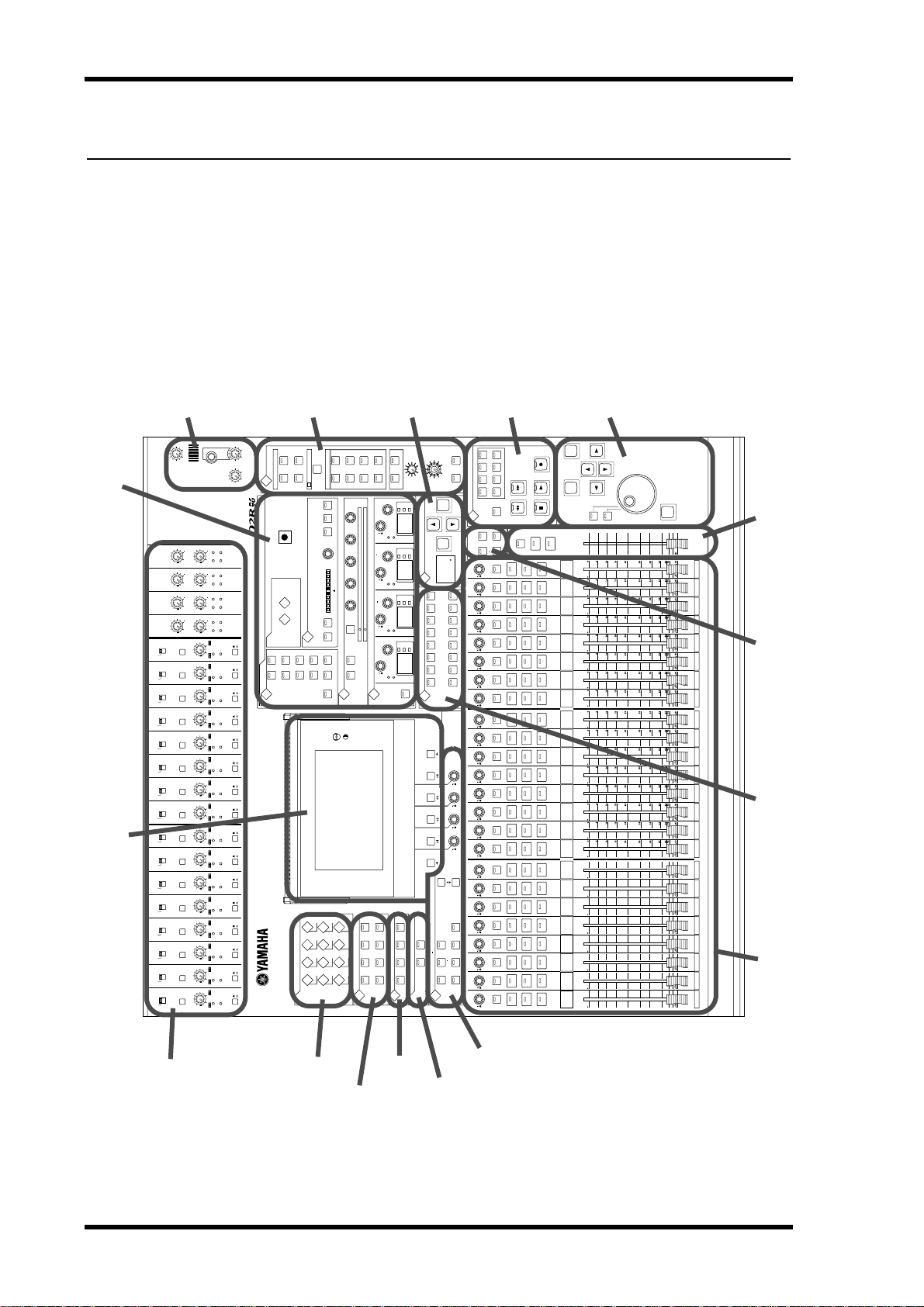
2 Control Surface & Rear Panel . . . . . . . . . . . . . . . . . 4
Control Surface . . . . . . . . . . . . . . . . . . . . . . . . . . . . . . . . . . . . . . . . . . . . . . . . . . . . . . 4
Rear Panel . . . . . . . . . . . . . . . . . . . . . . . . . . . . . . . . . . . . . . . . . . . . . . . . . . . . . . . . . 23
3 Operating Basics . . . . . . . . . . . . . . . . . . . . . . . . . . 29
Connecting the Power Cord . . . . . . . . . . . . . . . . . . . . . . . . . . . . . . . . . . . . . . . . . . . 29
Turning On & Off the 02R96 . . . . . . . . . . . . . . . . . . . . . . . . . . . . . . . . . . . . . . . . . . 29
About the Display . . . . . . . . . . . . . . . . . . . . . . . . . . . . . . . . . . . . . . . . . . . . . . . . . . . 29
Selecting Display Pages . . . . . . . . . . . . . . . . . . . . . . . . . . . . . . . . . . . . . . . . . . . . . . . 31
Display Parameter Boxes . . . . . . . . . . . . . . . . . . . . . . . . . . . . . . . . . . . . . . . . . . . . . 31
Parameter Windows . . . . . . . . . . . . . . . . . . . . . . . . . . . . . . . . . . . . . . . . . . . . . . . . . 31
Confirmation Messages . . . . . . . . . . . . . . . . . . . . . . . . . . . . . . . . . . . . . . . . . . . . . . 32
Title Edit Window . . . . . . . . . . . . . . . . . . . . . . . . . . . . . . . . . . . . . . . . . . . . . . . . . . . 32
Selecting Layers . . . . . . . . . . . . . . . . . . . . . . . . . . . . . . . . . . . . . . . . . . . . . . . . . . . . . 33
Selecting Channels . . . . . . . . . . . . . . . . . . . . . . . . . . . . . . . . . . . . . . . . . . . . . . . . . . . 34
Selecting Fader Modes . . . . . . . . . . . . . . . . . . . . . . . . . . . . . . . . . . . . . . . . . . . . . . . 35
Selecting Encoder Modes . . . . . . . . . . . . . . . . . . . . . . . . . . . . . . . . . . . . . . . . . . . . . 36
Assigning Parameters to the ENCODER MODE Assign Buttons . . . . . . . . . . . . . 37
v
4 Analog I/O & the AD Input Section . . . . . . . . . . . 39
AD Input Section . . . . . . . . . . . . . . . . . . . . . . . . . . . . . . . . . . . . . . . . . . . . . . . . . . . . 39
Stereo Out . . . . . . . . . . . . . . . . . . . . . . . . . . . . . . . . . . . . . . . . . . . . . . . . . . . . . . . . . 40
Control Room Monitor Out . . . . . . . . . . . . . . . . . . . . . . . . . . . . . . . . . . . . . . . . . . 40
Studio Monitor Out . . . . . . . . . . . . . . . . . . . . . . . . . . . . . . . . . . . . . . . . . . . . . . . . . 40
Omni Outs . . . . . . . . . . . . . . . . . . . . . . . . . . . . . . . . . . . . . . . . . . . . . . . . . . . . . . . . . 40
2TR Analog INs . . . . . . . . . . . . . . . . . . . . . . . . . . . . . . . . . . . . . . . . . . . . . . . . . . . . . 40
5 Digital I/O & Cascading . . . . . . . . . . . . . . . . . . . . 41
Wordclocks . . . . . . . . . . . . . . . . . . . . . . . . . . . . . . . . . . . . . . . . . . . . . . . . . . . . . . . . 41
2TR Digital Outs . . . . . . . . . . . . . . . . . . . . . . . . . . . . . . . . . . . . . . . . . . . . . . . . . . . . 43
2TR Digital Ins . . . . . . . . . . . . . . . . . . . . . . . . . . . . . . . . . . . . . . . . . . . . . . . . . . . . . . 44
2TR In Sampling Rate Conversion . . . . . . . . . . . . . . . . . . . . . . . . . . . . . . . . . . . . . 44
Slot I/O . . . . . . . . . . . . . . . . . . . . . . . . . . . . . . . . . . . . . . . . . . . . . . . . . . . . . . . . . . . . 45
Dithering Digital Outputs . . . . . . . . . . . . . . . . . . . . . . . . . . . . . . . . . . . . . . . . . . . . 48
Monitoring Digital Input Channel Status . . . . . . . . . . . . . . . . . . . . . . . . . . . . . . . . 48
Cascading Consoles . . . . . . . . . . . . . . . . . . . . . . . . . . . . . . . . . . . . . . . . . . . . . . . . . . 49
6 Input & Output Patching . . . . . . . . . . . . . . . . . . . 52
Input Patching . . . . . . . . . . . . . . . . . . . . . . . . . . . . . . . . . . . . . . . . . . . . . . . . . . . . . . 52
Output Patching . . . . . . . . . . . . . . . . . . . . . . . . . . . . . . . . . . . . . . . . . . . . . . . . . . . . 54
Naming Input & Output Ports . . . . . . . . . . . . . . . . . . . . . . . . . . . . . . . . . . . . . . . . . 57
Patch Select Window . . . . . . . . . . . . . . . . . . . . . . . . . . . . . . . . . . . . . . . . . . . . . . . . 57
Patching with the Encoders . . . . . . . . . . . . . . . . . . . . . . . . . . . . . . . . . . . . . . . . . . . 58
02R96—Owner’s Manual

vi
7 Input Channels . . . . . . . . . . . . . . . . . . . . . . . . . . . . 59
Patching Input Channels . . . . . . . . . . . . . . . . . . . . . . . . . . . . . . . . . . . . . . . . . . . . . 59
Metering Input Channels . . . . . . . . . . . . . . . . . . . . . . . . . . . . . . . . . . . . . . . . . . . . . 59
Reversing the Signal Phase . . . . . . . . . . . . . . . . . . . . . . . . . . . . . . . . . . . . . . . . . . . . 59
Gating Input Channels . . . . . . . . . . . . . . . . . . . . . . . . . . . . . . . . . . . . . . . . . . . . . . . 60
Attenuating Input Channels . . . . . . . . . . . . . . . . . . . . . . . . . . . . . . . . . . . . . . . . . . 61
EQ’ing Input Channels . . . . . . . . . . . . . . . . . . . . . . . . . . . . . . . . . . . . . . . . . . . . . . . 61
Grouping Input Channel EQs . . . . . . . . . . . . . . . . . . . . . . . . . . . . . . . . . . . . . . . . . 62
Input Channel Inserts . . . . . . . . . . . . . . . . . . . . . . . . . . . . . . . . . . . . . . . . . . . . . . . . 62
Compressing Input Channels . . . . . . . . . . . . . . . . . . . . . . . . . . . . . . . . . . . . . . . . . 62
Grouping Input Channel Compressors . . . . . . . . . . . . . . . . . . . . . . . . . . . . . . . . . 63
Delaying Input Channels . . . . . . . . . . . . . . . . . . . . . . . . . . . . . . . . . . . . . . . . . . . . . 63
Muting Input Channels (ON/OFF) . . . . . . . . . . . . . . . . . . . . . . . . . . . . . . . . . . . . 63
Grouping Input Channel Mutes (ON/OFF) . . . . . . . . . . . . . . . . . . . . . . . . . . . . . 64
Setting Input Channel Levels . . . . . . . . . . . . . . . . . . . . . . . . . . . . . . . . . . . . . . . . . . 65
Grouping Input Channel Faders . . . . . . . . . . . . . . . . . . . . . . . . . . . . . . . . . . . . . . . 65
Routing Input Channels . . . . . . . . . . . . . . . . . . . . . . . . . . . . . . . . . . . . . . . . . . . . . . 66
Panning Input Channels . . . . . . . . . . . . . . . . . . . . . . . . . . . . . . . . . . . . . . . . . . . . . 67
Using Surround Pan . . . . . . . . . . . . . . . . . . . . . . . . . . . . . . . . . . . . . . . . . . . . . . . . . 69
Sending Input Channels to Aux Sends . . . . . . . . . . . . . . . . . . . . . . . . . . . . . . . . . . 72
Soloing Input Channels . . . . . . . . . . . . . . . . . . . . . . . . . . . . . . . . . . . . . . . . . . . . . . 72
Direct Outs . . . . . . . . . . . . . . . . . . . . . . . . . . . . . . . . . . . . . . . . . . . . . . . . . . . . . . . . 72
Pairing Input Channels . . . . . . . . . . . . . . . . . . . . . . . . . . . . . . . . . . . . . . . . . . . . . . 72
Using MS Decoding . . . . . . . . . . . . . . . . . . . . . . . . . . . . . . . . . . . . . . . . . . . . . . . . . 72
Viewing Input Channel Settings . . . . . . . . . . . . . . . . . . . . . . . . . . . . . . . . . . . . . . . 72
Naming Input Channels . . . . . . . . . . . . . . . . . . . . . . . . . . . . . . . . . . . . . . . . . . . . . . 72
8 Stereo Out . . . . . . . . . . . . . . . . . . . . . . . . . . . . . . . 73
Stereo Out Connectors . . . . . . . . . . . . . . . . . . . . . . . . . . . . . . . . . . . . . . . . . . . . . . . 73
Patching the Stereo Out to Outputs . . . . . . . . . . . . . . . . . . . . . . . . . . . . . . . . . . . . 73
Routing Input Channels to the Stereo Out . . . . . . . . . . . . . . . . . . . . . . . . . . . . . . 73
Sending Bus Outs to the Stereo Out . . . . . . . . . . . . . . . . . . . . . . . . . . . . . . . . . . . . 73
Metering the Stereo Out . . . . . . . . . . . . . . . . . . . . . . . . . . . . . . . . . . . . . . . . . . . . . . 73
Monitoring the Stereo Out . . . . . . . . . . . . . . . . . . . . . . . . . . . . . . . . . . . . . . . . . . . 73
Attenuating the Stereo Out . . . . . . . . . . . . . . . . . . . . . . . . . . . . . . . . . . . . . . . . . . . 73
EQ’ing the Stereo Out . . . . . . . . . . . . . . . . . . . . . . . . . . . . . . . . . . . . . . . . . . . . . . . 73
Grouping Master EQs . . . . . . . . . . . . . . . . . . . . . . . . . . . . . . . . . . . . . . . . . . . . . . . . 73
Stereo Out Inserts . . . . . . . . . . . . . . . . . . . . . . . . . . . . . . . . . . . . . . . . . . . . . . . . . . . 74
Compressing the Stereo Out . . . . . . . . . . . . . . . . . . . . . . . . . . . . . . . . . . . . . . . . . . 74
Grouping Master Compressors . . . . . . . . . . . . . . . . . . . . . . . . . . . . . . . . . . . . . . . . 74
Muting the Stereo Out (ON/OFF) . . . . . . . . . . . . . . . . . . . . . . . . . . . . . . . . . . . . . 74
Grouping Master Mutes (ON/OFF) . . . . . . . . . . . . . . . . . . . . . . . . . . . . . . . . . . . . 74
Setting the Stereo Out Level . . . . . . . . . . . . . . . . . . . . . . . . . . . . . . . . . . . . . . . . . . . 74
Grouping Master Faders . . . . . . . . . . . . . . . . . . . . . . . . . . . . . . . . . . . . . . . . . . . . . 74
Balancing the Stereo Out . . . . . . . . . . . . . . . . . . . . . . . . . . . . . . . . . . . . . . . . . . . . . 75
Delaying the Stereo Out . . . . . . . . . . . . . . . . . . . . . . . . . . . . . . . . . . . . . . . . . . . . . . 75
Viewing Stereo Out Settings . . . . . . . . . . . . . . . . . . . . . . . . . . . . . . . . . . . . . . . . . . 75
Naming the Stereo Out . . . . . . . . . . . . . . . . . . . . . . . . . . . . . . . . . . . . . . . . . . . . . . 75
02R96—Owner’s Manual

9 Bus Outs . . . . . . . . . . . . . . . . . . . . . . . . . . . . . . . . . 76
Patching Bus Outs to Outputs . . . . . . . . . . . . . . . . . . . . . . . . . . . . . . . . . . . . . . . . . 76
Routing Input Channels to Bus Outs . . . . . . . . . . . . . . . . . . . . . . . . . . . . . . . . . . . 76
Metering Bus Outs . . . . . . . . . . . . . . . . . . . . . . . . . . . . . . . . . . . . . . . . . . . . . . . . . . 76
Monitoring Bus Outs . . . . . . . . . . . . . . . . . . . . . . . . . . . . . . . . . . . . . . . . . . . . . . . . 76
Attenuating Bus Outs . . . . . . . . . . . . . . . . . . . . . . . . . . . . . . . . . . . . . . . . . . . . . . . . 76
EQ’ing Bus Outs . . . . . . . . . . . . . . . . . . . . . . . . . . . . . . . . . . . . . . . . . . . . . . . . . . . . 76
Grouping Master EQs . . . . . . . . . . . . . . . . . . . . . . . . . . . . . . . . . . . . . . . . . . . . . . . . 76
Bus Out Inserts . . . . . . . . . . . . . . . . . . . . . . . . . . . . . . . . . . . . . . . . . . . . . . . . . . . . . 76
Compressing Bus Outs . . . . . . . . . . . . . . . . . . . . . . . . . . . . . . . . . . . . . . . . . . . . . . . 76
Grouping Master Compressors . . . . . . . . . . . . . . . . . . . . . . . . . . . . . . . . . . . . . . . . 76
Muting Bus Outs (ON/OFF) . . . . . . . . . . . . . . . . . . . . . . . . . . . . . . . . . . . . . . . . . . 77
Grouping Master Mutes (ON/OFF) . . . . . . . . . . . . . . . . . . . . . . . . . . . . . . . . . . . . 77
Setting Bus Out Levels . . . . . . . . . . . . . . . . . . . . . . . . . . . . . . . . . . . . . . . . . . . . . . . 77
Grouping Master Faders . . . . . . . . . . . . . . . . . . . . . . . . . . . . . . . . . . . . . . . . . . . . . . 77
Delaying Bus Outs . . . . . . . . . . . . . . . . . . . . . . . . . . . . . . . . . . . . . . . . . . . . . . . . . . . 77
Soloing Bus Outs . . . . . . . . . . . . . . . . . . . . . . . . . . . . . . . . . . . . . . . . . . . . . . . . . . . . 77
Pairing Bus Outs . . . . . . . . . . . . . . . . . . . . . . . . . . . . . . . . . . . . . . . . . . . . . . . . . . . . 77
Sending Bus Outs to the Stereo Out . . . . . . . . . . . . . . . . . . . . . . . . . . . . . . . . . . . . 78
Viewing Bus Out Settings . . . . . . . . . . . . . . . . . . . . . . . . . . . . . . . . . . . . . . . . . . . . . 78
Naming Bus Outs . . . . . . . . . . . . . . . . . . . . . . . . . . . . . . . . . . . . . . . . . . . . . . . . . . . 78
vii
10 Aux Sends . . . . . . . . . . . . . . . . . . . . . . . . . . . . . . . 79
Patching Aux Send Masters to Outputs . . . . . . . . . . . . . . . . . . . . . . . . . . . . . . . . . 79
Setting the Aux Send Mode . . . . . . . . . . . . . . . . . . . . . . . . . . . . . . . . . . . . . . . . . . . 79
Pre-Fader or Post-Fader Aux Sends . . . . . . . . . . . . . . . . . . . . . . . . . . . . . . . . . . . . 79
Setting Aux Send Levels . . . . . . . . . . . . . . . . . . . . . . . . . . . . . . . . . . . . . . . . . . . . . . 80
Aux Send Pages . . . . . . . . . . . . . . . . . . . . . . . . . . . . . . . . . . . . . . . . . . . . . . . . . . . . . 80
Viewing Aux Send Settings . . . . . . . . . . . . . . . . . . . . . . . . . . . . . . . . . . . . . . . . . . . . 82
Panning Aux Sends . . . . . . . . . . . . . . . . . . . . . . . . . . . . . . . . . . . . . . . . . . . . . . . . . . 84
Metering Aux Send Masters . . . . . . . . . . . . . . . . . . . . . . . . . . . . . . . . . . . . . . . . . . . 85
Monitoring Aux Send Masters . . . . . . . . . . . . . . . . . . . . . . . . . . . . . . . . . . . . . . . . . 85
Attenuating Aux Send Masters . . . . . . . . . . . . . . . . . . . . . . . . . . . . . . . . . . . . . . . . . 85
EQ’ing Aux Send Masters . . . . . . . . . . . . . . . . . . . . . . . . . . . . . . . . . . . . . . . . . . . . . 85
Grouping Master EQs . . . . . . . . . . . . . . . . . . . . . . . . . . . . . . . . . . . . . . . . . . . . . . . . 85
Aux Send Master Inserts . . . . . . . . . . . . . . . . . . . . . . . . . . . . . . . . . . . . . . . . . . . . . . 85
Compressing Aux Send Masters . . . . . . . . . . . . . . . . . . . . . . . . . . . . . . . . . . . . . . . 85
Grouping Master Compressors . . . . . . . . . . . . . . . . . . . . . . . . . . . . . . . . . . . . . . . . 85
Muting Aux Send Masters (ON/OFF) . . . . . . . . . . . . . . . . . . . . . . . . . . . . . . . . . . . 85
Grouping Master Mutes (ON/OFF) . . . . . . . . . . . . . . . . . . . . . . . . . . . . . . . . . . . . 85
Settings Aux Send Master Levels . . . . . . . . . . . . . . . . . . . . . . . . . . . . . . . . . . . . . . . 86
Grouping Master Faders . . . . . . . . . . . . . . . . . . . . . . . . . . . . . . . . . . . . . . . . . . . . . . 86
Delaying Aux Send Masters . . . . . . . . . . . . . . . . . . . . . . . . . . . . . . . . . . . . . . . . . . . 86
Soloing Aux Sends . . . . . . . . . . . . . . . . . . . . . . . . . . . . . . . . . . . . . . . . . . . . . . . . . . . 86
Pairing Aux Sends . . . . . . . . . . . . . . . . . . . . . . . . . . . . . . . . . . . . . . . . . . . . . . . . . . . 86
Viewing Aux Send Master Settings . . . . . . . . . . . . . . . . . . . . . . . . . . . . . . . . . . . . . 86
Naming Aux Send Masters . . . . . . . . . . . . . . . . . . . . . . . . . . . . . . . . . . . . . . . . . . . . 86
02R96—Owner’s Manual

viii
11 Common Channel Functions . . . . . . . . . . . . . . . . . 87
Metering . . . . . . . . . . . . . . . . . . . . . . . . . . . . . . . . . . . . . . . . . . . . . . . . . . . . . . . . . . 87
Attenuating Signals . . . . . . . . . . . . . . . . . . . . . . . . . . . . . . . . . . . . . . . . . . . . . . . . . . 90
Using EQ . . . . . . . . . . . . . . . . . . . . . . . . . . . . . . . . . . . . . . . . . . . . . . . . . . . . . . . . . . 91
Grouping Output Channel EQs . . . . . . . . . . . . . . . . . . . . . . . . . . . . . . . . . . . . . . . 94
Using Inserts . . . . . . . . . . . . . . . . . . . . . . . . . . . . . . . . . . . . . . . . . . . . . . . . . . . . . . . 95
Compressing Channels . . . . . . . . . . . . . . . . . . . . . . . . . . . . . . . . . . . . . . . . . . . . . . . 97
Grouping Output Channel Compressors . . . . . . . . . . . . . . . . . . . . . . . . . . . . . . . . 100
Delaying Channel Signals . . . . . . . . . . . . . . . . . . . . . . . . . . . . . . . . . . . . . . . . . . . . . 101
Soloing Channels . . . . . . . . . . . . . . . . . . . . . . . . . . . . . . . . . . . . . . . . . . . . . . . . . . . 102
Pairing Channels . . . . . . . . . . . . . . . . . . . . . . . . . . . . . . . . . . . . . . . . . . . . . . . . . . . . 104
Grouping Output Channel Faders . . . . . . . . . . . . . . . . . . . . . . . . . . . . . . . . . . . . . 106
Grouping Output Channel Mutes (ON/OFF) . . . . . . . . . . . . . . . . . . . . . . . . . . . . 107
Viewing Channel Parameter Settings . . . . . . . . . . . . . . . . . . . . . . . . . . . . . . . . . . . 108
Viewing Channel Fader Settings . . . . . . . . . . . . . . . . . . . . . . . . . . . . . . . . . . . . . . . 109
Naming Channels . . . . . . . . . . . . . . . . . . . . . . . . . . . . . . . . . . . . . . . . . . . . . . . . . . . 112
12 Monitoring & Talkback . . . . . . . . . . . . . . . . . . . . . 114
Control Room Monitoring . . . . . . . . . . . . . . . . . . . . . . . . . . . . . . . . . . . . . . . . . . . 114
Studio Monitoring . . . . . . . . . . . . . . . . . . . . . . . . . . . . . . . . . . . . . . . . . . . . . . . . . . 115
Surround Monitoring . . . . . . . . . . . . . . . . . . . . . . . . . . . . . . . . . . . . . . . . . . . . . . . . 116
Using Talkback . . . . . . . . . . . . . . . . . . . . . . . . . . . . . . . . . . . . . . . . . . . . . . . . . . . . . 121
13 Libraries . . . . . . . . . . . . . . . . . . . . . . . . . . . . . . . . 122
About the Libraries . . . . . . . . . . . . . . . . . . . . . . . . . . . . . . . . . . . . . . . . . . . . . . . . . . 122
General Library Operation . . . . . . . . . . . . . . . . . . . . . . . . . . . . . . . . . . . . . . . . . . . . 122
Channel Library . . . . . . . . . . . . . . . . . . . . . . . . . . . . . . . . . . . . . . . . . . . . . . . . . . . . 123
Input Patch Library . . . . . . . . . . . . . . . . . . . . . . . . . . . . . . . . . . . . . . . . . . . . . . . . . 124
Output Patch Library . . . . . . . . . . . . . . . . . . . . . . . . . . . . . . . . . . . . . . . . . . . . . . . . 124
Effects Library . . . . . . . . . . . . . . . . . . . . . . . . . . . . . . . . . . . . . . . . . . . . . . . . . . . . . . 125
Bus to Stereo Library . . . . . . . . . . . . . . . . . . . . . . . . . . . . . . . . . . . . . . . . . . . . . . . . 126
Gate Library . . . . . . . . . . . . . . . . . . . . . . . . . . . . . . . . . . . . . . . . . . . . . . . . . . . . . . . . 127
Comp Library . . . . . . . . . . . . . . . . . . . . . . . . . . . . . . . . . . . . . . . . . . . . . . . . . . . . . . 128
EQ Library . . . . . . . . . . . . . . . . . . . . . . . . . . . . . . . . . . . . . . . . . . . . . . . . . . . . . . . . . 129
Automix Library . . . . . . . . . . . . . . . . . . . . . . . . . . . . . . . . . . . . . . . . . . . . . . . . . . . . 130
Surround Monitor Library . . . . . . . . . . . . . . . . . . . . . . . . . . . . . . . . . . . . . . . . . . . . 130
14 Internal Effects & Plug-Ins . . . . . . . . . . . . . . . . . . 131
About the Effects . . . . . . . . . . . . . . . . . . . . . . . . . . . . . . . . . . . . . . . . . . . . . . . . . . . . 131
Patching Effects Processors . . . . . . . . . . . . . . . . . . . . . . . . . . . . . . . . . . . . . . . . . . . 131
Preset Effects & Types . . . . . . . . . . . . . . . . . . . . . . . . . . . . . . . . . . . . . . . . . . . . . . . . 131
Editing Effects . . . . . . . . . . . . . . . . . . . . . . . . . . . . . . . . . . . . . . . . . . . . . . . . . . . . . . 133
About Plug-Ins . . . . . . . . . . . . . . . . . . . . . . . . . . . . . . . . . . . . . . . . . . . . . . . . . . . . . 135
Configuring Plug-Ins . . . . . . . . . . . . . . . . . . . . . . . . . . . . . . . . . . . . . . . . . . . . . . . . 135
Editing Plug-Ins . . . . . . . . . . . . . . . . . . . . . . . . . . . . . . . . . . . . . . . . . . . . . . . . . . . . 136
15 Scene Memories . . . . . . . . . . . . . . . . . . . . . . . . . . 138
02R96—Owner’s Manual
About Scene Memories . . . . . . . . . . . . . . . . . . . . . . . . . . . . . . . . . . . . . . . . . . . . . . 138
Auto Scene Memory Update . . . . . . . . . . . . . . . . . . . . . . . . . . . . . . . . . . . . . . . . . . 139
Storing & Recalling Scenes with the SCENE MEMORY Buttons . . . . . . . . . . . . . 140
Using the Scene Memory Page . . . . . . . . . . . . . . . . . . . . . . . . . . . . . . . . . . . . . . . . 141
Fading Scenes . . . . . . . . . . . . . . . . . . . . . . . . . . . . . . . . . . . . . . . . . . . . . . . . . . . . . . 142
Recalling Scenes Safely . . . . . . . . . . . . . . . . . . . . . . . . . . . . . . . . . . . . . . . . . . . . . . . 143
Sorting Scenes . . . . . . . . . . . . . . . . . . . . . . . . . . . . . . . . . . . . . . . . . . . . . . . . . . . . . . 144

16 Automix . . . . . . . . . . . . . . . . . . . . . . . . . . . . . . . . . 145
About Automix . . . . . . . . . . . . . . . . . . . . . . . . . . . . . . . . . . . . . . . . . . . . . . . . . . . . . 145
What’s Recorded in an Automix? . . . . . . . . . . . . . . . . . . . . . . . . . . . . . . . . . . . . . . 145
Automix Main Page . . . . . . . . . . . . . . . . . . . . . . . . . . . . . . . . . . . . . . . . . . . . . . . . . 146
Channel Strip [AUTO] Buttons . . . . . . . . . . . . . . . . . . . . . . . . . . . . . . . . . . . . . . . . 149
Automix Memory Page . . . . . . . . . . . . . . . . . . . . . . . . . . . . . . . . . . . . . . . . . . . . . . . 150
Fader Edit Pages . . . . . . . . . . . . . . . . . . . . . . . . . . . . . . . . . . . . . . . . . . . . . . . . . . . . 151
Selecting the Timecode Source & Frame Rate . . . . . . . . . . . . . . . . . . . . . . . . . . . . 152
Creating a Time Signature Map . . . . . . . . . . . . . . . . . . . . . . . . . . . . . . . . . . . . . . . . 153
Recording an Automix . . . . . . . . . . . . . . . . . . . . . . . . . . . . . . . . . . . . . . . . . . . . . . . 154
Rerecording Events . . . . . . . . . . . . . . . . . . . . . . . . . . . . . . . . . . . . . . . . . . . . . . . . . . 154
Parameter Recording . . . . . . . . . . . . . . . . . . . . . . . . . . . . . . . . . . . . . . . . . . . . . . . . 155
Punching In & Out Individual Parameters . . . . . . . . . . . . . . . . . . . . . . . . . . . . . . . 156
Playing Back an Automix . . . . . . . . . . . . . . . . . . . . . . . . . . . . . . . . . . . . . . . . . . . . . 157
Editing Events Offline . . . . . . . . . . . . . . . . . . . . . . . . . . . . . . . . . . . . . . . . . . . . . . . . 158
17 MIDI . . . . . . . . . . . . . . . . . . . . . . . . . . . . . . . . . . . . 163
MIDI & the 02R96 . . . . . . . . . . . . . . . . . . . . . . . . . . . . . . . . . . . . . . . . . . . . . . . . . . . 163
MIDI I/O . . . . . . . . . . . . . . . . . . . . . . . . . . . . . . . . . . . . . . . . . . . . . . . . . . . . . . . . . . 163
MIDI Port Setup . . . . . . . . . . . . . . . . . . . . . . . . . . . . . . . . . . . . . . . . . . . . . . . . . . . . 164
MIDI Channel Setup . . . . . . . . . . . . . . . . . . . . . . . . . . . . . . . . . . . . . . . . . . . . . . . . . 165
Assigning Scenes to Program Changes . . . . . . . . . . . . . . . . . . . . . . . . . . . . . . . . . . 166
Assigning Parameters to Control Changes . . . . . . . . . . . . . . . . . . . . . . . . . . . . . . . 167
Controlling Parameters by Using Parameter Changes . . . . . . . . . . . . . . . . . . . . . 167
Using Bulk Dump . . . . . . . . . . . . . . . . . . . . . . . . . . . . . . . . . . . . . . . . . . . . . . . . . . . 168
ix
18 Pro Tools Remote Layer . . . . . . . . . . . . . . . . . . . . 169
Configuring Windows Computers . . . . . . . . . . . . . . . . . . . . . . . . . . . . . . . . . . . . . 169
Configuring Macintosh Computers . . . . . . . . . . . . . . . . . . . . . . . . . . . . . . . . . . . . 169
Configuring the 02R96 . . . . . . . . . . . . . . . . . . . . . . . . . . . . . . . . . . . . . . . . . . . . . . . 169
Configuring Pro Tools . . . . . . . . . . . . . . . . . . . . . . . . . . . . . . . . . . . . . . . . . . . . . . . 170
Control Surface Operation with the Pro Tools Remote Layer . . . . . . . . . . . . . . . 171
Selecting Channels . . . . . . . . . . . . . . . . . . . . . . . . . . . . . . . . . . . . . . . . . . . . . . . . . . . 179
Setting Channel Levels . . . . . . . . . . . . . . . . . . . . . . . . . . . . . . . . . . . . . . . . . . . . . . . 179
Muting Channels . . . . . . . . . . . . . . . . . . . . . . . . . . . . . . . . . . . . . . . . . . . . . . . . . . . . 179
Panning Channels . . . . . . . . . . . . . . . . . . . . . . . . . . . . . . . . . . . . . . . . . . . . . . . . . . . 179
Soloing Channels . . . . . . . . . . . . . . . . . . . . . . . . . . . . . . . . . . . . . . . . . . . . . . . . . . . . 179
Viewing Send Destinations . . . . . . . . . . . . . . . . . . . . . . . . . . . . . . . . . . . . . . . . . . . . 180
Configuring Sends as Pre or Post . . . . . . . . . . . . . . . . . . . . . . . . . . . . . . . . . . . . . . . 180
Setting Send Levels . . . . . . . . . . . . . . . . . . . . . . . . . . . . . . . . . . . . . . . . . . . . . . . . . . 180
Muting Sends . . . . . . . . . . . . . . . . . . . . . . . . . . . . . . . . . . . . . . . . . . . . . . . . . . . . . . . 180
Panning Sends . . . . . . . . . . . . . . . . . . . . . . . . . . . . . . . . . . . . . . . . . . . . . . . . . . . . . . 180
Flip Mode . . . . . . . . . . . . . . . . . . . . . . . . . . . . . . . . . . . . . . . . . . . . . . . . . . . . . . . . . . 181
Assigning Inserts/Plug-ins . . . . . . . . . . . . . . . . . . . . . . . . . . . . . . . . . . . . . . . . . . . . 182
Editing Plug-ins . . . . . . . . . . . . . . . . . . . . . . . . . . . . . . . . . . . . . . . . . . . . . . . . . . . . . 183
Bypassing Plug-ins . . . . . . . . . . . . . . . . . . . . . . . . . . . . . . . . . . . . . . . . . . . . . . . . . . 184
Resetting Faders, Sends, & Panpots . . . . . . . . . . . . . . . . . . . . . . . . . . . . . . . . . . . . . 184
Navigating the Edit Window . . . . . . . . . . . . . . . . . . . . . . . . . . . . . . . . . . . . . . . . . . 184
Zooming . . . . . . . . . . . . . . . . . . . . . . . . . . . . . . . . . . . . . . . . . . . . . . . . . . . . . . . . . . . 185
Making Fine Adjustments to the Selected Region . . . . . . . . . . . . . . . . . . . . . . . . . 185
Scrub & Shuttle . . . . . . . . . . . . . . . . . . . . . . . . . . . . . . . . . . . . . . . . . . . . . . . . . . . . . 186
Automation . . . . . . . . . . . . . . . . . . . . . . . . . . . . . . . . . . . . . . . . . . . . . . . . . . . . . . . . 187
02R96—Owner’s Manual

x
19 Remote Control . . . . . . . . . . . . . . . . . . . . . . . . . . 189
About the Remote Layer . . . . . . . . . . . . . . . . . . . . . . . . . . . . . . . . . . . . . . . . . . . . . 189
Assigning a Target to the Remote Layer . . . . . . . . . . . . . . . . . . . . . . . . . . . . . . . . . 189
Configuring the User Defined Remote Layer . . . . . . . . . . . . . . . . . . . . . . . . . . . . . 190
Using the User Defined Remote Layer . . . . . . . . . . . . . . . . . . . . . . . . . . . . . . . . . . 191
About Machine Control . . . . . . . . . . . . . . . . . . . . . . . . . . . . . . . . . . . . . . . . . . . . . . 192
Configuring Machines . . . . . . . . . . . . . . . . . . . . . . . . . . . . . . . . . . . . . . . . . . . . . . . 192
Transport Buttons . . . . . . . . . . . . . . . . . . . . . . . . . . . . . . . . . . . . . . . . . . . . . . . . . . 193
Using Shuttle & Scrub . . . . . . . . . . . . . . . . . . . . . . . . . . . . . . . . . . . . . . . . . . . . . . . 193
Using the Locator . . . . . . . . . . . . . . . . . . . . . . . . . . . . . . . . . . . . . . . . . . . . . . . . . . . 194
Setting the Locate Memories . . . . . . . . . . . . . . . . . . . . . . . . . . . . . . . . . . . . . . . . . . 194
GPI (General Purpose Interface) . . . . . . . . . . . . . . . . . . . . . . . . . . . . . . . . . . . . . . . 195
20 Other Functions . . . . . . . . . . . . . . . . . . . . . . . . . . 196
Using the User Defined Keys . . . . . . . . . . . . . . . . . . . . . . . . . . . . . . . . . . . . . . . . . . 196
Setting Preferences . . . . . . . . . . . . . . . . . . . . . . . . . . . . . . . . . . . . . . . . . . . . . . . . . . 197
Using the Oscillator . . . . . . . . . . . . . . . . . . . . . . . . . . . . . . . . . . . . . . . . . . . . . . . . . 200
Checking the Battery . . . . . . . . . . . . . . . . . . . . . . . . . . . . . . . . . . . . . . . . . . . . . . . . 200
Initializing the 02R96 . . . . . . . . . . . . . . . . . . . . . . . . . . . . . . . . . . . . . . . . . . . . . . . . 201
Appendix A: Parameter Lists . . . . . . . . . . . . . . . . . . . 202
USER DEFINED KEYS . . . . . . . . . . . . . . . . . . . . . . . . . . . . . . . . . . . . . . . . . . . . . . . 202
USER DEFINED KEYS Initial Assignments . . . . . . . . . . . . . . . . . . . . . . . . . . . . . . 204
Input Patch Parameters . . . . . . . . . . . . . . . . . . . . . . . . . . . . . . . . . . . . . . . . . . . . . . 204
Initial Input Patch Settings . . . . . . . . . . . . . . . . . . . . . . . . . . . . . . . . . . . . . . . . . . . 207
Output Patch Parameters . . . . . . . . . . . . . . . . . . . . . . . . . . . . . . . . . . . . . . . . . . . . . 208
Initial Output Patch Settings . . . . . . . . . . . . . . . . . . . . . . . . . . . . . . . . . . . . . . . . . . 213
Initial Input Channel Names . . . . . . . . . . . . . . . . . . . . . . . . . . . . . . . . . . . . . . . . . . 214
Initial Output Channel Names . . . . . . . . . . . . . . . . . . . . . . . . . . . . . . . . . . . . . . . . 214
Initial Input Port Names . . . . . . . . . . . . . . . . . . . . . . . . . . . . . . . . . . . . . . . . . . . . . 215
Initial Output Port Names . . . . . . . . . . . . . . . . . . . . . . . . . . . . . . . . . . . . . . . . . . . . 216
GPI Trigger Source List . . . . . . . . . . . . . . . . . . . . . . . . . . . . . . . . . . . . . . . . . . . . . . 217
User Defined Remote Layer Initial Bank Settings . . . . . . . . . . . . . . . . . . . . . . . . . 219
Effects Parameters . . . . . . . . . . . . . . . . . . . . . . . . . . . . . . . . . . . . . . . . . . . . . . . . . . . 223
Preset EQ Parameters . . . . . . . . . . . . . . . . . . . . . . . . . . . . . . . . . . . . . . . . . . . . . . . . 251
Preset Gate Parameters (fs = 44.1 kHz) . . . . . . . . . . . . . . . . . . . . . . . . . . . . . . . . . 255
Preset Compressor Parameters (fs = 44.1 kHz) . . . . . . . . . . . . . . . . . . . . . . . . . . . 255
Appendix B: Specifications . . . . . . . . . . . . . . . . . . . . . 260
General Spec . . . . . . . . . . . . . . . . . . . . . . . . . . . . . . . . . . . . . . . . . . . . . . . . . . . . . . . 260
Controls . . . . . . . . . . . . . . . . . . . . . . . . . . . . . . . . . . . . . . . . . . . . . . . . . . . . . . . . . . . 265
Indicators . . . . . . . . . . . . . . . . . . . . . . . . . . . . . . . . . . . . . . . . . . . . . . . . . . . . . . . . . . 267
Libraries . . . . . . . . . . . . . . . . . . . . . . . . . . . . . . . . . . . . . . . . . . . . . . . . . . . . . . . . . . . 267
Analog Input Spec . . . . . . . . . . . . . . . . . . . . . . . . . . . . . . . . . . . . . . . . . . . . . . . . . . . 268
Analog Output Spec . . . . . . . . . . . . . . . . . . . . . . . . . . . . . . . . . . . . . . . . . . . . . . . . . 268
Digital Input Spec . . . . . . . . . . . . . . . . . . . . . . . . . . . . . . . . . . . . . . . . . . . . . . . . . . . 269
Digital Output Spec . . . . . . . . . . . . . . . . . . . . . . . . . . . . . . . . . . . . . . . . . . . . . . . . . 269
I/O Slot Spec . . . . . . . . . . . . . . . . . . . . . . . . . . . . . . . . . . . . . . . . . . . . . . . . . . . . . . . 270
Control I/O Spec . . . . . . . . . . . . . . . . . . . . . . . . . . . . . . . . . . . . . . . . . . . . . . . . . . . . 270
Connector Pin Assignments . . . . . . . . . . . . . . . . . . . . . . . . . . . . . . . . . . . . . . . . . . 271
Dimensions . . . . . . . . . . . . . . . . . . . . . . . . . . . . . . . . . . . . . . . . . . . . . . . . . . . . . . . . 272
02R96—Owner’s Manual

Appendix C: MIDI . . . . . . . . . . . . . . . . . . . . . . . . . . . . 273
Scene Memory to Program Change Table . . . . . . . . . . . . . . . . . . . . . . . . . . . . . . . 273
Initial Parameter to Control Change Table . . . . . . . . . . . . . . . . . . . . . . . . . . . . . . 274
MIDI Data Format . . . . . . . . . . . . . . . . . . . . . . . . . . . . . . . . . . . . . . . . . . . . . . . . . . 275
Format Details . . . . . . . . . . . . . . . . . . . . . . . . . . . . . . . . . . . . . . . . . . . . . . . . . . . . . . 275
Appendix D: Options . . . . . . . . . . . . . . . . . . . . . . . . . . 288
MB02R96 Peak Meter Bridge . . . . . . . . . . . . . . . . . . . . . . . . . . . . . . . . . . . . . . . . . . 288
SP02R96 Wooden Side Panels . . . . . . . . . . . . . . . . . . . . . . . . . . . . . . . . . . . . . . . . . 290
Index . . . . . . . . . . . . . . . . . . . . . . . . . . . . . . . . . . . . . . 291
xi
02R96—Owner’s Manual

1 Welcome
Thank you for choosing the Yamaha 02R96 Digital Mixing Console.
The 02R96 Digital Mixing Console offers 24-bit/96 kHz digital audio processing without
compromise, comprehensive surround mixing and monitoring, including bass management, and hands-on control of popular DAW (Digital Audio Workstation) systems.
Sonic Spec
• Linear 24-bit, 128-times oversampling A/D converters
• Linear 24-bit, 128-times oversampling D/A converters
• 20 Hz–40 kHz (0.5, –1.5 dB) frequency response at 96 kHz sampling rate
• 105 dB typical dynamic range (AD Input to Stereo Out)
• 32-bit internal signal processing (58-bit accumulator)
Channel Architecture
• 56 Input Channels, with Direct Outs
• 8 Bus Outs, with to Stereo Out routing for subgrouping
• 8 Aux Sends
• Stereo Out
• Channels can be named for easy identification
• Channel library with 127 user memories
Welcome
1
I/O Architecture
• 16 analog mic inputs on balanced XLRs (plus 48 V phantom) 24 analog line inputs on balanced phone jacks
• 16 analog inserts
• 32 inputs, 32 outputs via four mini-YGDAI slots and optional I/O cards, which
ety of analog and digital I/O options, with support for all the popular digital audio
interconnect formats, including AES/EBU, ADAT, Tascam TDIF-1, and mLAN.
• 8 assignable Omni outputs
• 1 AES/EBU, 2 Coaxial 2-track digital input, with sampling rate converters for connecting
44.1/48 kHz legacy digital audio equipment
• 1 AES/EBU, 2 Coaxial 2-track digital output
• 2 analog 2-track inputs
• XLR and phono connector stereo outputs
• Control room monitor outputs
• Dedicated studio monitor outputs
• Double channel digital I/O for use with legacy 44.1/48 kHz multitrack recorders
• Cascade ports for cascading up to four 02R96s (i.e., 224 Input Channels)
offer a vari-
02R96—Owner’s Manual

2
Chapter 1—Welcome
I/O Patching
• Any available input port can be patched to the Input Channels, Insert Ins, or Effects inputs
• Direct Outs, Insert Outs, Bus Outs, Aux Sends, and the Stereo Out can be patched to any
output port
• Input and output ports can be named for easy identification
• Patches can be stored in the Input and Output Patch libraries
EQ
• 4-band parametric EQ on all Input and Output Channels
• EQ library with 40 presets, 160 user memories
Groups & Pairs
• Horizontal and vertical pairing of Input Channels
• Horizontal pairing of Bus Outs, Aux Sends, and Surround Pan
• 8 Input Channel, 4 Output Channel Fader groups
• 8 Input Channel, 4 Output Channel Mute groups
• 4 Input Channel, 4 Output Channel EQ groups
• 4 Input Channel, 4 Output Channel Compressor groups
Effects
• 4 internal effects processors
• Effects library with 52 presets, 76 user memories
• Multichannel effects for surround sound processing
• Joystick control of early reflections and reverb with the Reverb 5.1 effect
• Optional Waves 56K effects plug-in cards
• User defined plug-ins for external effects control via MIDI, with Learn function
Dynamics
• Gates on all 56 Input Channels
• Gate library with 4 presets, 124 user memories
• Compressors on all Input Channels and Out Channels (74 in total)
• Compressor library with 36 presets, 92 user memories
Automation
• Dynamic automation of virtually all mix parameters, with 1/4-frame accuracy
• Automix library with 16 memories
• Snapshot style automation with 99 Scene memories, recallable via MIDI or Automix
• Individual fade time settings for all Input and Output faders
• Scene and library recalls
• Punch in/out entire channels with dedicated [AUTO] buttons, or individual parameters
• Editing fader moves with Fader Return, Fader Takeover, Absolute/Relative modes
• Offline event editing includes, erase, copy, move/merge, trim, duplicate, delete, and insert
02R96—Owner’s Manual

Welcome
Surround Sound
• 3-1 and 5.1 Surround modes
• Joystick control
• Bass management
• Monitor matrix
• Surround monitor speaker alignment functions
• Surround monitor library with 32 user memories
Remote Control
• Control and manage your 02R96 from your Mac or PC by using the bundled Studio Manager software
• Remote Layers for external equipment control, including predefined targets for controlling
DAW systems, and user defined targets for controlling MIDI equipment, with Learn function
• Comprehensive machine control via MMC, including transport, track arming, jog/shuttle,
and built-in locator with eight Locate memories
• Assignable GPI (General Purpose Interface) port for external control and “Recording” light
3
MIDI
• Standard MIDI ports, USB TO HOST port, SERIAL TO HOST port, or mLAN MIDI I/O
• USB, SERIAL, and mLAN option offer multiport operation
• Scene recall, mix parameter control, Bulk Dump, MTC and MIDI Clock for Automix synchronization, MMC for external machine control
Control Surface
• 25 touch-sensitive 100-mm motorized faders (touch sense used to select channels or punch
faders in/out during Automix recording)
• Use the faders to set channel levels or Aux Send levels
• Use the 24 Encoders to control Pan, Aux Send levels, or user assigned parameters
• Channels arranged into two Input Layers, Master Layer, and Remote Layer
• 320 x 240 dot LCD display with fluorescent backlight
• Complete hands-on control of all channel functions via the SELECTED CHANNEL section
• 2-digit Scene memory display
• 4 EQ displays for frequency, gain, and Q
• 16 user-definable buttons make light work of repetitive tasks
02R96—Owner’s Manual
4
Chapter 2—Control Surface & Rear Panel
2 Control Surface & Rear Panel
Control Surface
Monitor, Phones & Talkback
Section (p. 19)
LEVEL
PHONES
010
TALKBACKLEVEL
23
24
34
GAIN
10
+
21
22
34
GAIN
10
+
20
19
SELECTED CHANNEL Section (p. 11)
Display Section (p. 10)
34
GAIN
10
+
18
17
34
GAIN
10
+
ON
OFF
48V
26dB
+
ON
OFF
48V
26dB
+
ON
OFF
48V
26dB
+
ON
OFF
48V
26dB
+
ON
OFF
48V
26dB
+
ON
OFF
48V
26dB
+
ON
OFF
48V
26dB
+
ON
OFF
48V
26dB
+
ON
OFF
48V
26dB
+
ON
OFF
48V
26dB
+
ON
OFF
48V
26dB
+
ON
OFF
48V
26dB
+
ON
OFF
48V
26dB
+
ON
OFF
48V
26dB
+
ON
OFF
48V
26dB
+
ON
OFF
48V
26dB
+
PAD
010
PHONES
MONITOR
LEVEL
STUDIO
010
34
GAIN
PEAK
SIGNAL
10
+
34
10
+
34
10
+
34
10
+
-60
-16
-60
-16
-60
-16
-60
-16
-60
-16
-60
-16
-60
-16
-60
-16
-60
-16
-60
-16
-60
-16
-60
-16
-60
-16
-60
-16
-60
-16
-60
-16
DIGITAL MIXING CONSOLE
GAIN
PEAK
SIGNAL
GAIN
PEAK
SIGNAL
19 20 21 22 23 24
GAIN
GAIN
GAIN
GAIN
GAIN
GAIN
GAIN
GAIN
GAIN
GAIN
GAIN
GAIN
GAIN
GAIN
GAIN
GAIN
GAIN
SELECTED CHANNEL
PEAK
SIGNAL
17 18
ON
OFF
INSERT
PEAK
SIGNAL
ON
OFF
INSERT
PEAK
SIGNAL
ROUTING
ON
OFF
INSERT
PEAK
SIGNAL
ON
OFF
INSERT
PEAK
SIGNAL
ON
OFF
INSERT
PEAK
SIGNAL
ON
OFF
INSERT
PEAK
SIGNAL
ON
OFF
INSERT
PEAK
SIGNAL
ON
OFF
INSERT
PEAK
SIGNAL
ON
OFF
8
INSERT
PEAK
SIGNAL
ON
OFF
7
INSERT
PEAK
SIGNAL
ON
OFF
6
INSERT
PEAK
SIGNAL
ON
OFF
5
INSERT
PEAK
SIGNAL
ON
OFF
4
INSERT
PEAK
SIGNAL
ON
OFF
3
INSERT
PEAK
SIGNAL
ON
OFF
2
INSERT
PEAK
SIGNAL
ON
OFF
1 9 10 11 12 13 14 15 16
INSERT
PEAK
SIGNAL
MONITOR Section (p. 20)
STEREO
SOLO
DISPLAY
STUDIO
AUX7 AUX8
ROOM
CONTROL
DELAY
PHASE /
INSERT
DISPLAY ACCESS
PAN/ SUR ROUND
DISPLAY
4
56
12
3
DISPLAY
AUTOMIX DIO SETUP UTILITY
DISPLAYACCESS
CLEAR
CONTROL ROOM
LINK GRAB EFFECT
R
EVEN
L
ODD
LR
78
STEREOFOLLOWPAN DIRECT
MIDI REMOTE METER VIEW
SCENE MEMORY (p. 16)
SLOT
100
100
SURROUND MONITOR LEVEL
SCENE MEMORY
DISPLAY
12345678
USER DEFINED KEYS
DISPLAY
AUXFADER
EFFECTS / PLUG INS
DISPLAY
CONTROLROOM LEVEL
CHANNEL
PLUG INS
INTERNAL
STORE RECALL
00
INSERTS
EFFECTS
TALKBACK
DIMMER
910111213141516
1234
1 ASSIGN2
SURROUND
BUS
2TRD2 2TRA2
2TRD1 2TRA1
2TRD3 STEREO
ASSIGN
dB
Hz
kHz
GAIN
HIGH
GAIN
HOLD
Q
FREQUENCY
DECAY
RELEASE
dB
Hz
kHz
GAIN
HIGH MID
ATTACK
ATTACKTHRESHOLD
Q
FREQUENCY
RATIO
RANGE
dB
Hz
kHz
GAIN
LOW MID
THRESHOLD
Q
FREQUENCY
GATE
COMP
GATE/ COMP
dB
Hz
kHz
GAIN
LOW
125 1.00 4.00 10.0
Q
FREQUENCY
GATEON COMP ON
EQUALIZER
DYNAMICS
DISPLAY
OUTPUT
PATCH
PATCH
PAIR GROUP INPUT
AUXSELECT
EQON
DISPLAY
ASSIGN2ASSIGN1
AUXPAN
AUX6AUX5 AUX7 AUX 8
AUX2AUX1 AUX3 AUX 4
ENCODER MODE
FADER MODE
DISPLAY
DISPLAY
MACHINE CONTROL (p. 17)
REC
LOCATEMEMORY
5678
1234
MACHINE CONTROL
DISPLAY
LAYER
REW FF
STEREO
STOP PLAY
SEL
AUTO
ON
SEL
SOLO
ON
SEL
SOLO
ON
SEL
SOLO
ON
SEL
SOLO
ON
SEL
SOLO
ON
SEL
SOLO
ON
SEL
SOLO
ON
SEL
SOLO
ON
SEL
SOLO
ON
SEL
SOLO
ON
SEL
SOLO
ON
SEL
SOLO
ON
SEL
SOLO
ON
SEL
SOLO
ON
SEL
SOLO
ON
SEL
SOLO
ON
SEL
SOLO
ON
SEL
SOLO
ON
SEL
SOLO
ON
SEL
SOLO
ON
SEL
SOLO
ON
SEL
SOLO
ON
SEL
SOLO
ON
SEL
SOLO
SET
MASTER25 48
REMOTE1 24
AUTO
AUTO
AUTO
AUTO
AUTO
AUTO
AUTO
AUTO
AUTO
AUTO
AUTO
AUTO
AUTO
AUTO
AUTO
AUTO
AUTO
AUTO
AUTO
AUTO
AUTO
AUTO
AUTO
AUTO
Data Entry & Transport
(p. 18)
INCDEC
SCRUB
SHUTTLE
ON
5
0
15
10
10
505
10
505
10
505
10
505
10
505
10
505
10
505
10
505
10
505
10
505
10
505
10
505
10
505
10
505
10
505
10
505
10
505
10
505
10
505
10
505
10
505
10
505
10
505
1 2 3 4 5 6 7 8 9 10 11 12 13 14 15 16 17 18 19 2 0 21 2 2 23 2 4
10
505
ENTER
STEREO
50
70
60
40
30
20
5040302015
10
5040302015
10
5040302015
10
5040302015
10
5040302015
10
5040302015
10
5040302015
10
5040302015
10
5040302015
10
5040302015
10
5040302015
10
5040302015
10
5040302015
10
5040302015
10
5040302015
10
AUX 1 AUX 2 AUX 3 AUX 4 AUX 5 AUX 6 AUX 7 AUX 8 BUS 1 BUS 2 BUS 3 BUS 4 BUS 5 BUS 6 BUS 7 BUS 8
5040302015
10
5040302015
10
5040302015
10
5040302015
10
5040302015
10
5040302015
10
5040302015
10
5040302015
10
10
12345678 910111213141516 1718192021222324
25 26 27 28 29 30 31 32 33 34 35 36 37 38 39 40 41 42 43 44 45 46 47 48
49 50 51 52 53 54 55 56
5040302015
LAYER (p. 15) STEREO (p. 15)
USER DEFINED KEYS (p. 16)
Channel strips (p. 5)
AD Input Section (p. 5)
02R96—Owner’s Manual
AUX SELECT (p. 6)
DISPLAY ACCESS (p. 7)
ENCODER MODE (p. 6)
FADER MODE (p. 7)
EFFECTS/PLUG-INS (p. 9)
1
2
3
4
5
6
3
4
5
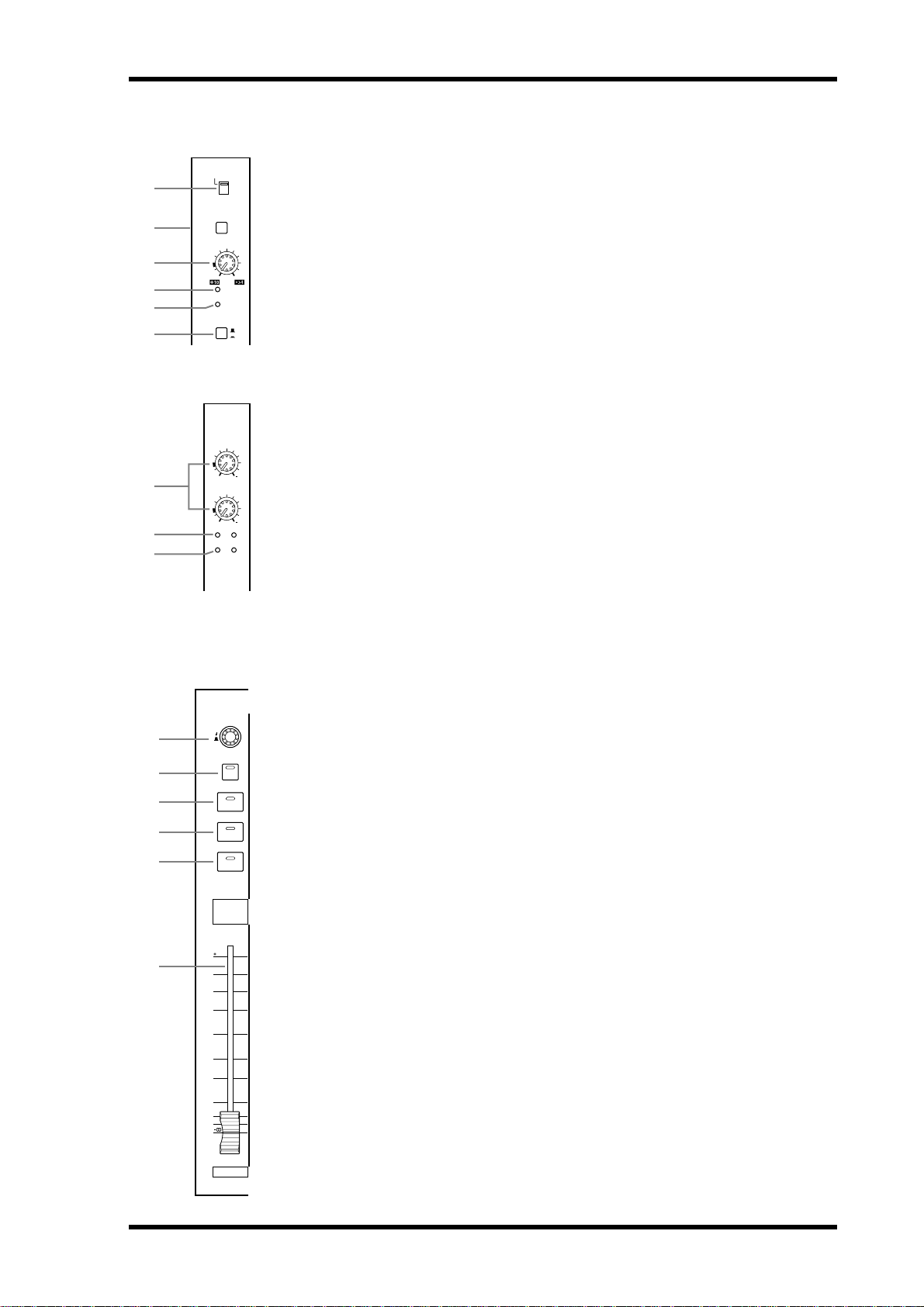
AD Input Section
AD Input #1 is shown at the top; AD Inputs #17 and #18 below.
+
48V
ON
OFF
A
These switches turn on and off the +48 V phantom power feed to each INPUT A
PAD
26dB
(XLR-type connector). Phantom power is typically used to power condenser-type
microphones or direct boxes. See “Phantom Power (AD 1–16)” on page 39 for more
information.
-60
-16
PEAK
SIGNAL
INSERT
GAIN
1
OFF
ON
B
These switches turn on and off the 26 dB pad (attenuator) for each AD Input. See “Pad
(AD 1–16)” on page 39 for more information.
C
These controls adjust the gain of the AD Input Head Amps. They have an input sensitivity of –16 dB to –60 dB or +10 dB to –34 dB when Pad is on. AD Inputs 17 to 24 have
an input sensitivity of +10 dB to –34 dB. See “Gain” on page 39 for more information.
+
10
GAIN
+
10
GAIN
PEAK
SIGNAL
17 18
17
34
18
34
D
These indicators light up when the input signal level is 3 dB below clipping. See “PEAK
& SIGNAL Indicators” on page 39 for more information.
E
These indicators light up when the input signal level is 20 dB below nominal. See
“PEAK & SIGNAL Indicators” on page 39 for more information.
F
These switches are for turning on and off the AD Input inserts. See “AD Inserts (AD
1–16)” on page 40 for more information.
+48V ON/OFF switches (AD 1–16)
PAD switches (AD 1–16)
GAIN controls
PEAK indicators
SIGNAL indicators
INSERT ON/OFF switches (AD 1–16)
Control Surface
5
1
2
3
4
5
6
Channel strips
Channel strip #1 is shown here.
The function of each channel strip depends on the currently selected Layer. See
“Selecting Layers” on page 33 for more information.
A
AUTO
SEL
SOLO
ON
1
10
5
0
5
10
15
20
30
40
50
1
25
49
These controls are used to edit Input and Output Channel parameters. Their exact
operation depends on the currently selected Encoder mode and Layer. There are two
preset Encoder modes, Pan and Aux, and two assignable modes, with over 40 parameters to choose from. See “Selecting Encoder Modes” on page 36 for more information.
The Encoders feature push switches that are used to punch the parameter currently
assigned to the Encoders in and out during Automix recording. See “Punching In &
Out Individual Parameters” on page 156 for more information.
B
These buttons are used to set Automix recording and playback for each channel.
Their exact operation depends on the currently selected Layer. Their indicators light
up orange in Record-Ready mode, red while recording, and green during playback.
See “Channel Strip [AUTO] Buttons” on page 149 for more information.
C SEL buttons
These buttons are used to select Input and Output Channels for editing with the
SELECTED CHANNEL section. Their exact operation depends on the currently
selected Layer. The [SEL] button indicator of the currently selected channel lights up.
See “Selecting Channels” on page 34 for more information. The [SEL] buttons can
also be used to pair channels, and to add and remove channels to and from the EQ,
Comp, Fader, and Mute groups.
Encoders
AUTO buttons
02R96—Owner’s Manual

6 Chapter 2—Control Surface & Rear Panel
D SOLO buttons
These buttons are used to solo Channels. The [SOLO] button indicators of channels that
are soloed light up. See “Soloing Channels” on page 102 for more information.
E ON buttons
These buttons are used to mute Input and Output Channels. Their exact operation depends
on the currently selected Layer. The [ON] button indicators of channels that are on light up.
F Channel faders
These 100 mm touch-sensitive motorized faders are used to set the levels of Input Channels,
Bus Outs, and Aux Sends. Their exact operation depends on the currently selected Fader
mode and Layer. See “Selecting Fader Modes” on page 35 for more information. Faders can
be grouped for simultaneous operation. See “Grouping Input Channel Faders” on page 65
and “Grouping Output Channel Faders” on page 106 for more information.
Faders can also be used to select Input and Output Channels. See “Auto Channel Select &
Touch Sense Select” on page 34 for more information. They can also be used to punch channels in and out during Automix recording. See “Punching In & Out Individual Parameters”
on page 156 for more information.
AUX SELECT
DISPLAY
AUX SELECT
AUX 2AUX 1 AUX 3 AUX 4
AUX 6AUX 5 AUX 7 AUX 8
1
2
AUX SELECT DISPLAY button
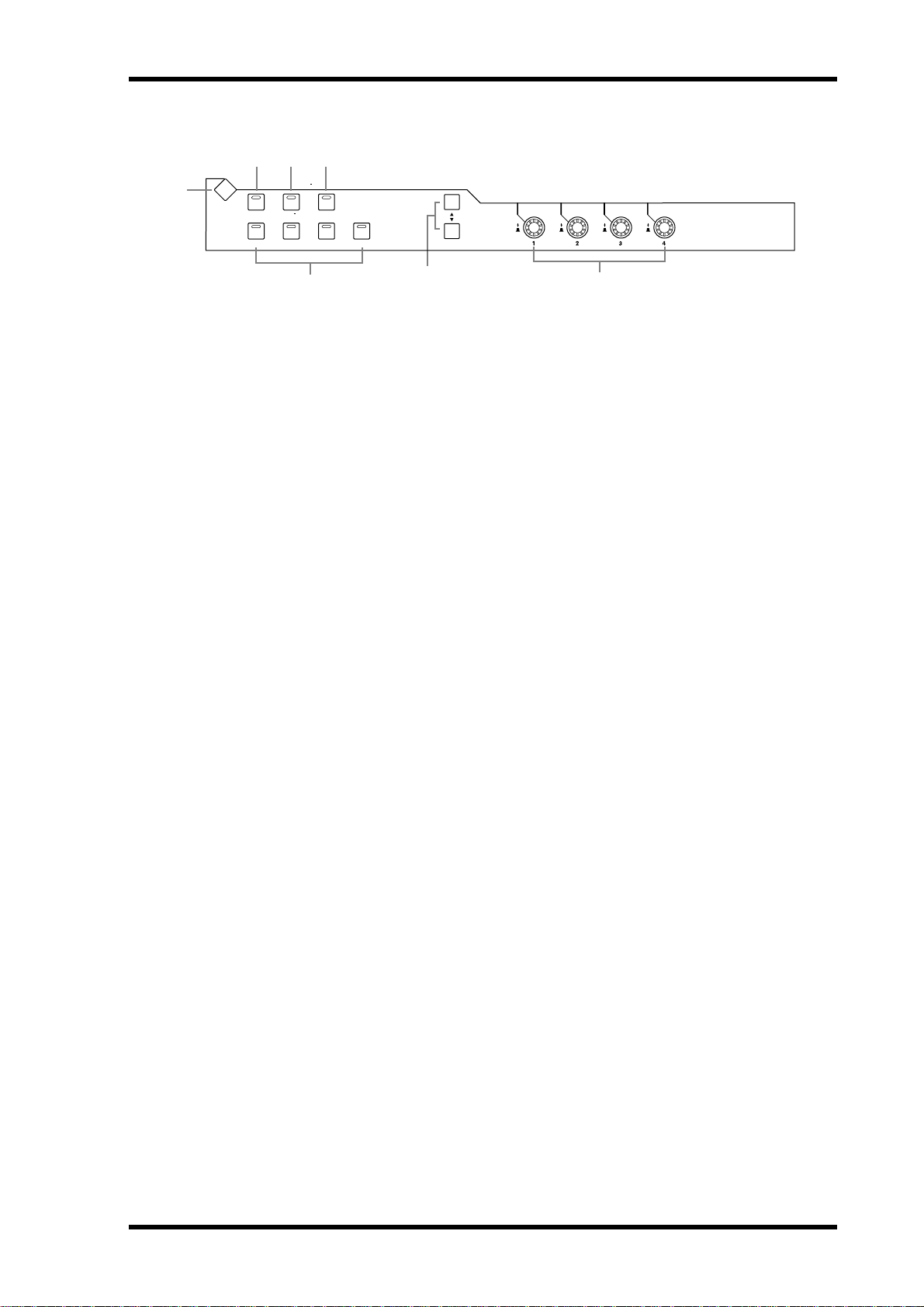
A
This button is used to select the following pages: Aux Send, Aux Send Pan, and Input Channel Aux View. See “Aux Sends” on page 79 for more information.
B AUX 1–8 buttons
These buttons are used to select Aux Sends when sending Input Channel signals to Aux
Sends. The button indicator of the currently selected Aux Send lights up. If the currently
selected Aux Send is paired, the indicator of its partner flashes. See “Aux Sends” on page 79
for more information. These buttons can also be used to pair Aux Sends. See “Pairing Channels” on page 104 for more information.
ENCODER MODE
DISPLAY
ENCODER MODE
AUXPAN
23
ASSIGN 2ASSIGN1
4
1
A
B PAN button
02R96—Owner’s Manual
ENCODER MODE DISPLAY button
This button is used to select the Encoder Mode Assign page. See “Selecting Encoder Modes”
on page 36 for more information.
This button is used to select the Pan Encoder mode. Its indicator lights up when this mode
is selected. In this mode, the Encoders function as Pan controls while an Input Channel
Layer is selected. While the Master Layer is selected, Encoders 1–8 function as Input Channel 49–56 Pan controls, and Encoders 9–24 are inactive. See “Selecting Encoder Modes” on
page 36 for more information.
Control Surface 7
C AUX button
This button is used to select the Aux Encoder mode. Its indicator lights up when this mode
is selected. In this mode, the Encoders function as Aux Send level controls when an Input
Channel Layer is selected. While the Master Layer is selected, Encoders 1–8 function as
Input Channel 49–56 Aux Send controls, and Encoders 9–24 are inactive. See “Selecting
Encoder Modes” on page 36.
D ASSIGN 1 & 2 buttons
These buttons are used to select the assignable Encoder modes. The button indicator for the
currently selected mode lights up. When an assignable mode is selected, the function of the
Encoders depends on the assigned parameter. Up to two parameters, from a list of over 40,
can be assigned to these two buttons. See “Assigning Parameters to the ENCODER MODE
Assign Buttons” on page 37 for more information.
FADER MODE
FADER MODE
AUXFADER
1 2
A FADER button
This button selects Fader mode, in which the faders control Input or Output Channel levels,
depending on the currently selected Layer. Its indicator lights up when this mode is selected.
See “Selecting Fader Modes” on page 35 for more information.
B AUX button
This button selects the Aux Fader mode, in which the faders control Aux Send levels. Its
indicator lights up when this mode is selected. See “Selecting Fader Modes” on page 35 for
more information.
DISPLAY ACCESS
1 2 3 4
DISPLAY ACCESS
5
6
AUTOMIX DIO SETUP UTILITY
MIDI REMOTE METER VIEW
PAIR GROUP INPUT
9
J K L
PATCH
OUTPUT
PATCH
7
8
A AUTOMIX button
This button is used to select the following Automix pages: Automix Main, Automix Memory, Fader Edit, Event Copy, and Event Edit. See “Automix” on page 145 for more information.
B DIO button
This button is used to select the following pages: Word Clock Select, Dither, Cascade In,
Cascade Out, Sampling Rate Converter, and Higher Sample Rate Data Format. See “Digital
I/O & Cascading” on page 41 for more information.
C SETUP button
This button is used to select the following pages: Preferences 1, Preferences 2, Preferences 3,
MIDI/TO HOST Setup, GPI Setup, Input Port Name, Output Port Name, Time Reference,
and Time Signature.
02R96—Owner’s Manual

8 Chapter 2—Control Surface & Rear Panel
D UTILITY button
This button is used to select the following pages: Oscillator, Channel Status Monitor, and
Battery Check.
E REMOTE button
This button is used to select the Remote page. See “About the Remote Layer” on page 189
for more information.
F MIDI button
This button is used to select the following pages: MIDI Setup, Program Change Assign
Table, Control Change Assign Table, and Bulk Dump. See “MIDI” on page 163 for more
information.
G METER button
This button is used to select the following pages: Input Channel Meter, Master Meter, Effect
1-4, Stereo Meter, and Metering Position. See “Metering” on page 87 for more information.
H VIEW button
This button is used to select the following pages: Parameter View, Fader View, and Channel
Library. See “Viewing Channel Parameter Settings” on page 108, “Viewing Channel Fader
Settings” on page 109, and “Channel Library” on page 123 for more information.
I PAIR button
This button is used to select the Input and Output Pair pages. See “Pairing Channels” on
page 104 for more information.
J GROUP button
This button is used to select the following pages: Input Channel Fader Group, Input Channel Mute Group, Output Fader Group, Output Mute Group, Input Equalizer Link, Output
Equalizer Link, Input Comp Link, and the Output Comp Link.
K INPUT PATCH button
This button is used to select the following pages: Input Channel Patch, Input Channel Insert
In Patch, Effects 1–4 Input Patch, Input Channel Name, and Input Patch Library. See “Input
Patching” on page 52 for more information.
L OUTPUT PATCH button
This button is used to select the following pages: Slot Output Patch, Omni Out Patch, Output Insert In Patch, Input Channel Direct Out Destination, 2TR Out Digital, Output Channel Name, and Output Patch Library. See “Output Patching” on page 54 for more
information.
02R96—Owner’s Manual
1
EFFECTS/PLUG-INS
2 3 4
EFFECTS / PLUG INS
DISPLAY
INTERNAL
EFFECTS
1234
PLUG INS
CHANNEL
INSERTS
Control Surface 9
5
A
EFFECTS/PLUG-INS DISPLAY button
6
7
This button is used to select the following pages: Effects Edit, Effects Library, Plug-In Setup,
and Plug-In Edit. See “Internal Effects & Plug-Ins” on page 131 for more information.
B INTERNAL EFFECTS button
This button is used to select the internal effects processors in conjunction with the
EFFECTS/PLUG-INS [1–4] buttons. Its indicator lights up when it’s pressed. See “Editing
Effects” on page 133 for more information.
C PLUG-INS button
This button is used to select the Plug-Ins in conjunction with the EFFECTS/PLUG-INS
[1–4] buttons. Its indicator lights up when it’s pressed. See “Editing Plug-Ins” on page 136
for more information.
D CHANNEL INSERTS button
If an internal effects processor or Y56K card effect is inserted in the currently selected channel, the relevant Effects Edit or Plug-In Edit page appears when this button is pressed, and
its indicator lights up. In addition, the corresponding EFFECTS/PLUG-INS [1–4] button
indicator flashes. If it’s a Y56K that is inserted, the [PLUG-INS] button indicator also
flashes. If it’s an internal effects processor, the [INTERNAL EFFECTS] button indicator
flashes. A warning message appears if there’s nothing inserted in the currently selected
channel. See “Editing Effects” on page 133 and “Editing Plug-Ins” on page 136 for more
information.
E EFFECTS/PLUG-INS 1–4 buttons
These buttons are used to select the internal effects processors and Plug-Ins in conjunction
with the EFFECTS/PLUG-INS [INTERNAL EFFECTS] and [PLUG-INS] buttons. The button indicator of the currently selected internal effects processor or Plug-In lights up. While
the EFFECTS/PLUG-INS [CHANNEL INSERTS] button indicator is lit, all of these buttons
are inactive.
F Parameter Up/Down buttons
These buttons are used to select the rows of internal effects processor and Plug-In parameters for editing with Parameter controls 1–4. The parameters in the currently selected row
appear highlighted. Up to 16 parameters can be displayed at a time. If more are available,
an up or down arrow is displayed. See “Editing Effects” on page 133 and “Editing Plug-Ins”
on page 136 for more information.
G Parameter controls 1–4
These are rotary controls and push switches. The rotary controls are used to edit the parameters of the currently selected internal effects processor or Plug-In. When the Effects Edit
page is selected, they control the currently selected row of parameters, rows being selected
by the Parameter Up/Down buttons. See “Editing Effects” on page 133 and “Editing
Plug-Ins” on page 136 for more information.
The push switches are used to punch the Effects or Plug-In parameters currently being controlled by the rotary controls in and out during Automix recording. See “Punching In & Out
Individual Parameters” on page 156 for more information.
02R96—Owner’s Manual
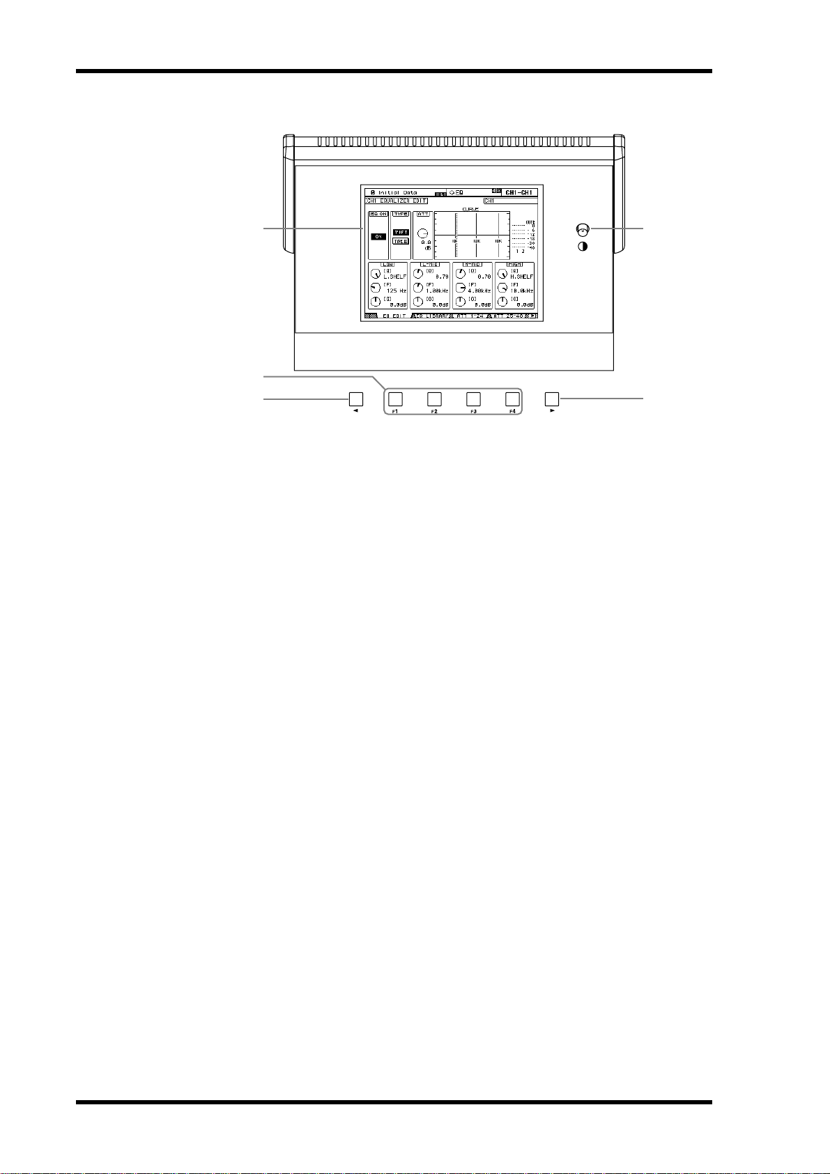
10 Chapter 2—Control Surface & Rear Panel
Display Section
1
2
3
4
A
Display
This 320 x 240 dot display with fluorescent backlight displays pages, information on the
currently selected Scene and channel, the sampling rate, and more. See “About the Display”
on page 29 for more information.
5
B Contrast control
This control is used to adjust the contrast of the display.
C F1–F4 buttons
These buttons are used to select the pages whose tabs are currently visible. See “Selecting
Display Pages” on page 31 for more information.
D Left Tab Scroll button
This button, which is active only when the left Tab Scroll arrow is displayed, is used to display the tabs of pages available to the left of the currently selected page. See “Selecting Display Pages” on page 31 for more information.
E Right Tab Scroll button
This button, which is active only when the right Tab Scroll arrow is displayed, is used to display the tabs of pages available to the right of the currently selected page. See “Selecting Display Pages” on page 31 for more information.
02R96—Owner’s Manual
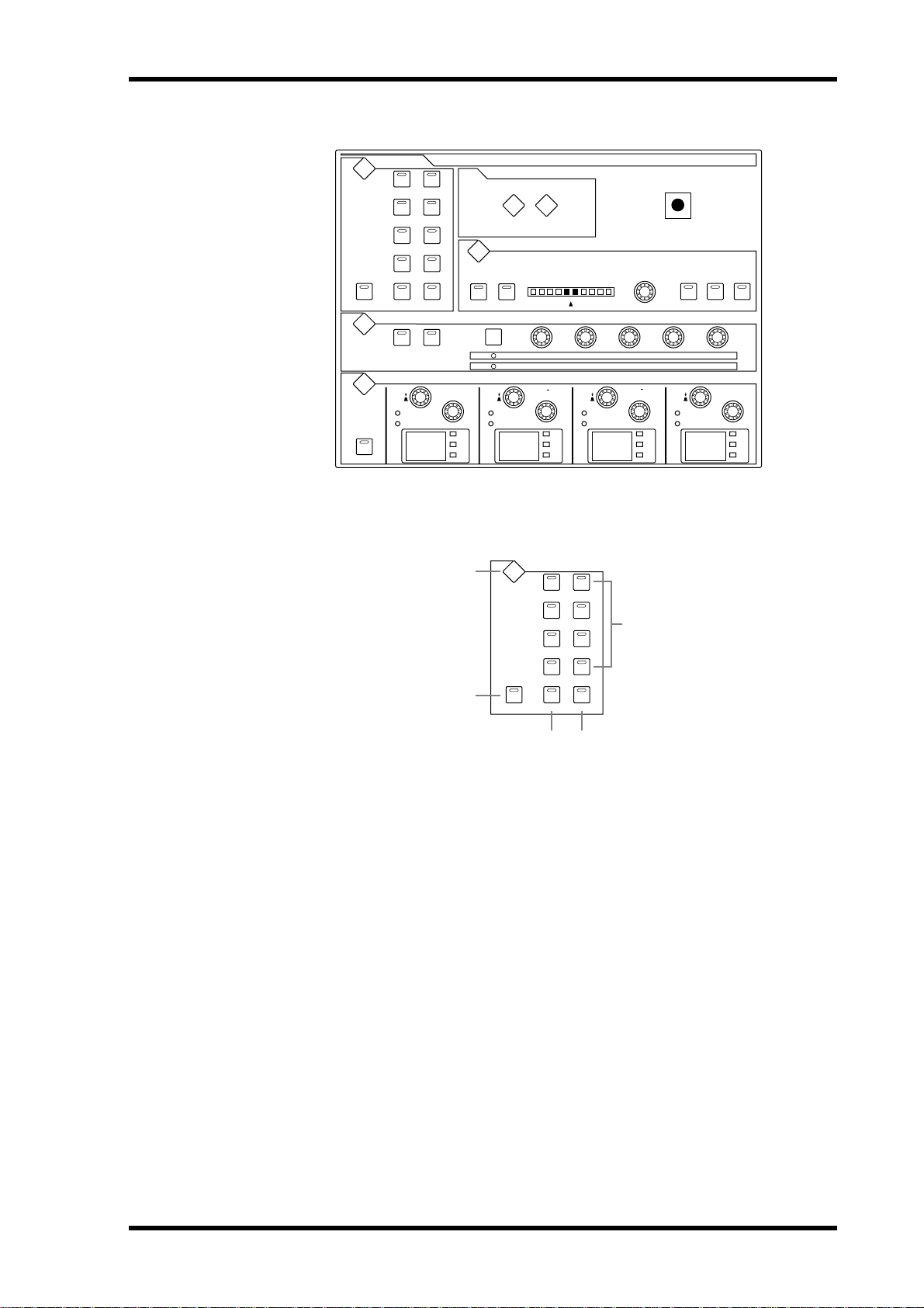
SELECTED CHANNEL Section
Control Surface 11
DISPLAY
LR
GATE / COMP
GATE
COMP
dB
Hz
kHz
SELECTED CHANNEL
DISPLAY ACCESS
PHASE /
DELAY
INSERT
PAN / SURROUND
L
ODD
THRESHOLD
LOW MID
FREQUENCY
Q
GAIN
dB
Hz
kHz
RANGE
RATIO
R
EVEN
FREQUENCY
Q
ATTA CK
ATTA CKTHRESHOLD
HIGH MID
GAIN
DECAY
RELEASE
dB
Hz
kHz
LINK GRAB EFFECT
HOLD
GAIN
HIGH
FREQUENCY
Q
GAIN
DISPLAY
DISPLAY
DISPLAY
EQ ON
ROUTING
12
4
3
56
78
STEREOFOLLOW PAN DIRECT
DYNAMICS
GATE ON COMP ON
EQUALIZER
FREQUENCY
Q
LOW
GAIN
125 1.00 4.00 10.0
The subsections of the SELECTED CHANNEL section are explained below.
ROUTING
DISPLAY
ROUTING
12
1
dB
Hz
kHz
4
2
3
56
78
STEREOFOLLOW PAN DIRECT
5
3 4
A ROUTING DISPLAY button
This button is used to select the following pages: Input Channel Routing, Bus to Stereo, and
Bus to Stereo Library. See “Routing Input Channels” on page 66 and “Sending Bus Outs to
the Stereo Out” on page 78 for more information.
B FOLLOW PAN button
This button determines whether or not the currently selected Input Channel’s pan setting
is applied to the Bus Outs. Its indicator lights up when it’s pressed. See “Routing Input
Channels” on page 66 for more information.
C STEREO button
This button is used to route the currently selected Input Channel to the Stereo Out. Its indicator lights up when it’s pressed. See “Routing Input Channels” on page 66 for more information.
D DIRECT button
This button is used to route the currently selected Input Channel to its Direct Out. Its indicator lights up when it’s pressed. See “Routing Input Channels” on page 66 for more information.
E ROUTING 1–8 buttons
These buttons are used to route the currently selected Input Channel to the Bus Outs. The
button indicators of Bus Outs to which the Input Channel is routed light up. See “Routing
Input Channels” on page 66 for more information.
02R96—Owner’s Manual
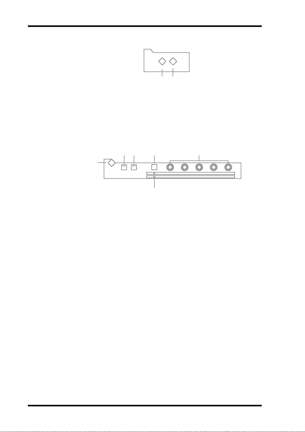
12 Chapter 2—Control Surface & Rear Panel
DISPLAY ACCESS
A PHASE/INSERT button
This button is used to select the Input Channel Phase and Insert pages. See “Reversing the
Signal Phase” on page 59 and “Using Inserts” on page 95 for more information.
B DELAY button
This button is used to select the Delay pages. See “Delaying Channel Signals” on page 101
for more information.
DYNAMICS
2
3 4 5
1
DISPLAY
DYNAMICS
GATE ON COMP ON
GATE / COMP
GATE
COMP
DISPLAY ACCESS
PHASE /
DELAY
INSERT
1 2
THRESHOLD
RANGE
RATIO
ATTA CK
ATTA CKTHRESHOLD
DECAY
RELEASE
HOLD
GAIN
6
A DYNAMICS DISPLAY button
This button is used to select the following pages: Gate Edit, Gate Library, Comp Edit, and
Comp Library. See “Gating Input Channels” on page 60 and “Compressing Channels” on
page 97 for more information.
B GATE ON button
This button is used to turn the currently selected Input Channel’s Gate on and off. Its indicator lights up when the Gate is on. See “Gating Input Channels” on page 60 for more information.
C COMP ON button
This button is used to turn the currently selected channel’s Compressor on and off. Its indicator lights up when the Compressor is on. See “Compressing Channels” on page 97 for
more information.
D GATE/COMP button
This button is used to set the rotary controls for either Gate or Compressor operation.
When an Output Channel is selected, Compressor is selected automatically and cannot be
changed. See “Gating Input Channels” on page 60 and “Compressing Channels” on page 97
for more information.
E THRESHOLD, RANGE, ATTACK, DECAY, HOLD (THRESHOLD, RATIO, ATTACK,
RELEASE, GAIN) controls
When the GATE/COMP button is set to GATE, these controls set the Threshold, Range,
Attack, Decay, and Hold parameters of the currently selected Input Channel’s Gate. When
it’s set to COMP, they set the Threshold, Ratio, Attack, Release, and Gain parameters of the
currently selected channel’s Compressor. See “Gating Input Channels” on page 60 and
“Compressing Channels” on page 97 for more information.
F GATE/COMP indicators
02R96—Owner’s Manual
These indicators show whether the rotary controls are set to control a Gate or Compressor.
The GATE indicator lights up when they’re set to control a Gate; the COMP indicator, when
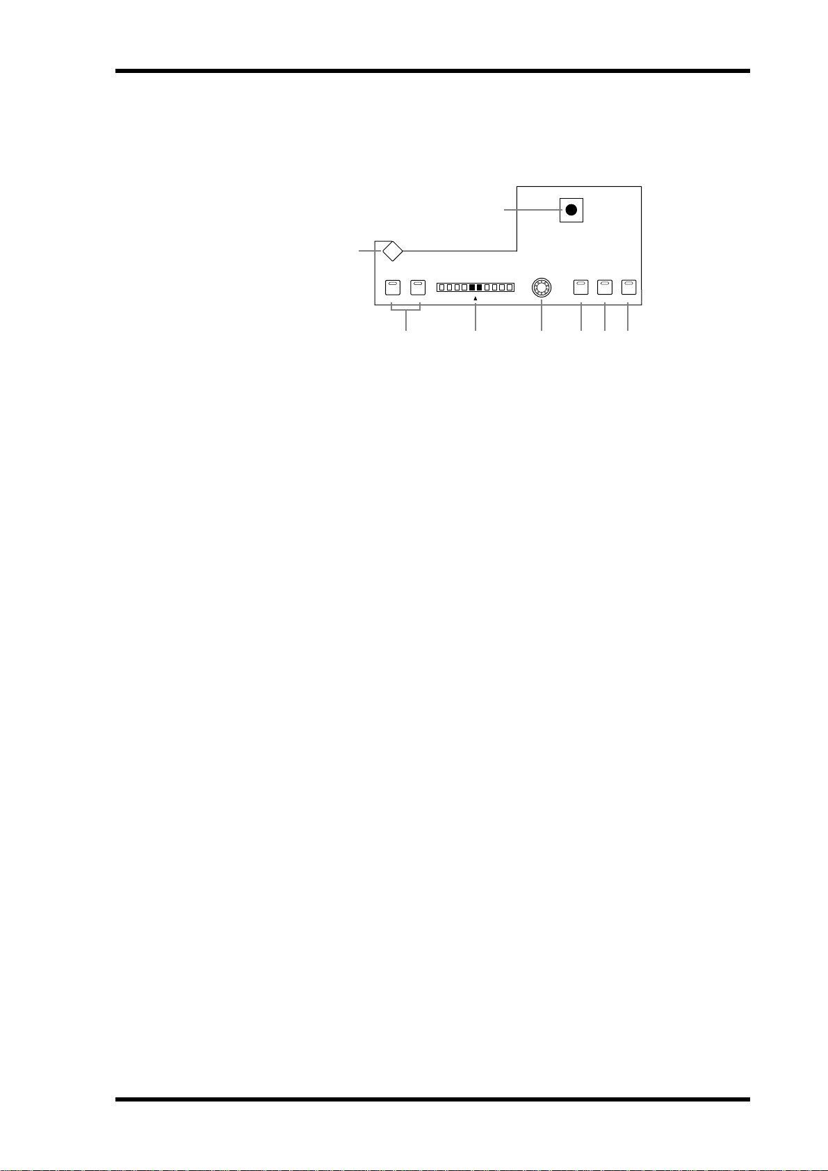
Control Surface 13
they’re set to control a Compressor. See “Gating Input Channels” on page 60 and “Compressing Channels” on page 97 for more information.
PAN/SURROUND
8
1
PAN / SURROUND
DISPLAY
LR
L
ODD
EVEN
R
LINK GRAB EFFECT
234567
A PAN/SURROUND DISPLAY button
This button is used to select the Input Channel Pan pages, the Surround Mode page, and
the Surround Edit pages. See “Panning Input Channels” on page 67 and “Using Surround
Pan” on page 69.
B L & R buttons
These buttons can be used to select horizontally or vertically partnered Input or Output
Channels. They can be used to select the left and right channels when the Stereo Out is
selected. For Input Channels, in Individual Pan mode, the [L] button indicator lights up
when an odd/left channel is selected; the [R] button indicator, when an even/right channel
is selected. In Gang or Inverse Gang Pan mode, the button indicator of the other channel in
the pair flashes while its partner is selected.
C PAN display
This 10-segment display indicates the pan position of the currently selected Input Channel.
When pan is set to center, the center two segments light up. When the Stereo Out is selected,
it displays the balance.
D PAN control
This rotary control is used to pan the currently selected Input Channel. When the Stereo
Out is selected, it is used to set the balance. For Input Channels in Gang or Inverse Gang
Pan mode, horizontally or vertically paired Input Channels are panned simultaneously. See
“Panning Input Channels” on page 67 and “Balancing the Stereo Out” on page 75.
E LINK button
This button, which is enabled only when a Surround mode other than Stereo is selected, is
used to link the PAN control and the Joystick so that either control can be used for normal
and surround panning. It’s a global setting that applies to all Input Channels. Its indicator
lights up when the PAN control and Joystick are linked. If the Joystick is set to control effects
(i.e., the [EFFECT] button indicator is lit), this button is disabled. See “Panning Input
Channels” on page 67 and “Using Surround Pan” on page 69 for more information.
F GRAB button
This button, which is enabled only when a Surround mode other than Stereo is selected, is
used to turn on and off Joystick control for the currently selected Input Channel. Its indicator lights up when Grab is on. When Grab is on, the Joystick can be used to control the
currently selected Input Channel’s surround pan position. When turned off, the Joystick
does not control surround pan. If the PAN control and the Joystick are linked (i.e., the
[LINK] button indicator is lit), Grab is turned off if the PAN control is adjusted. If the Joystick is set to control effects (i.e., the [EFFECT] button indicator is lit), this button is disabled.
02R96—Owner’s Manual
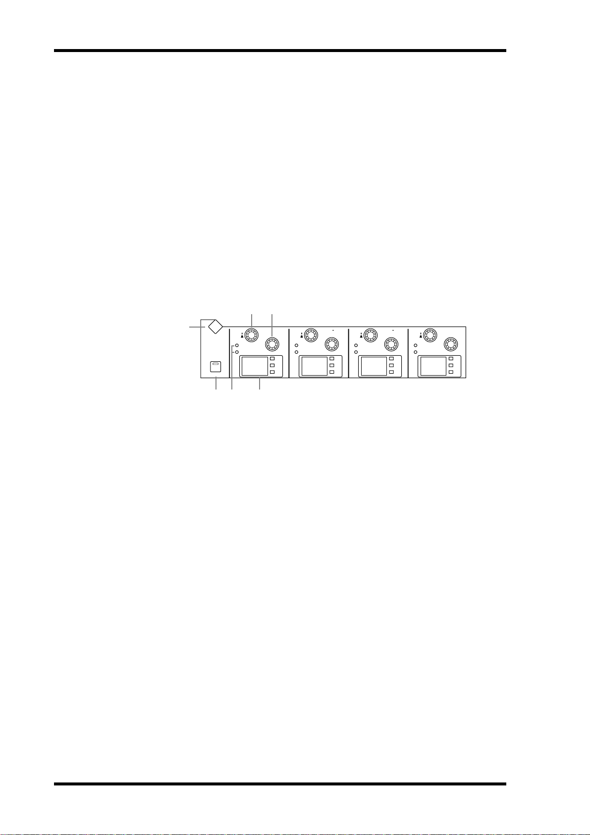
14 Chapter 2—Control Surface & Rear Panel
G EFFECT button
This button is used to select the Joystick for parameter control of the Reverb 5.1 effect. Its
indicator lights up when Reverb 5.1 effect control is on, and the Joystick cannot be used for
surround panning. See “REVERB 5.1” on page 245 for more information.
H Joystick
This control can be used for surround panning, normal panning, or parameter control of
the Reverb 5.1 effect. When the [EFFECT] button indicator is lit, the Joystick controls the
Reverb 5.1 effect. See “REVERB 5.1” on page 245 for more information. When the
[EFFECT] button indicator is off and the [GRAB] button indicator is on, the Joystick controls surround panning of the currently selected Input Channel. When the [EFFECT] button and [GRAB] button indicators are both off, the Joystick can still be used for surround
panning if the Auto Grab preference is on. See “Using Surround Pan” on page 69 for more
information. When the [EFFECT] button indicator is off but the [GRAB] button and
[LINK] button indicators are both on, the Joystick can be used for normal panning in unison with the PAN control. See “Panning Input Channels” on page 67 for more information.
EQUALIZER
2 3
1
DISPLAY
EQ ON
EQUALIZER
FREQUENCY
Q
LOW
GAIN
125 1.00 4.00 10.0
LOW MID
FREQUENCY
Q
GAIN
dB
Hz
kHz
dB
Hz
kHz
FREQUENCY
Q
HIGH MID
GAIN
HIGH
FREQUENCY
Q
GAIN
dB
Hz
kHz
dB
Hz
kHz
4 65
A EQUALIZER DISPLAY button
This button is used to select the following pages: Equalizer Edit, Equalizer Library, Input
Channel Attenuator/Shifter, and Output Attenuator.
B FREQUENCY/Q controls
These are rotary controls and push switches. The push switches are used to select either frequency or Q. The current setting is shown by the FREQUENCY/Q indicators. The rotary
controls are used to set the frequency or Q, as selected by the push switches. See “Using EQ”
on page 91 for more information.
C EQ GAIN controls
These controls are used to set the gain of each EQ band. See “Using EQ” on page 91 for more
information.
D EQ ON button
This button is used to turn the EQ of the currently selected channel on and off. Its indicator
lights up when the EQ is on. See “Using EQ” on page 91 for more information.
E FREQUENCY/Q indicators
These indicators show whether each FREQUENCY/Q control is set to control frequency or
Q. The FREQUENCY indicator lights up when it’s set to control frequency; the Q indicator,
when it’s set to control Q. See “Using EQ” on page 91 for more information.
F EQ displays
Normally these displays show the frequency of each band. When the GAIN is adjusted, the
gain value is displayed. When the Q is adjusted, the Q value is displayed. If the gain or Q is
not adjusted for two seconds, the frequency value reappears. See “Using EQ” on page 91 for
more information.
02R96—Owner’s Manual
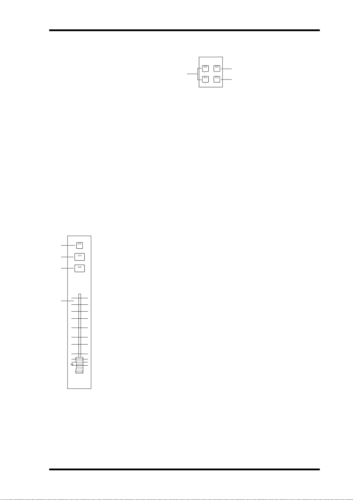
LAYER
Control Surface 15
LAYER
1
2
3
4
A 1–24 & 25–48 buttons
These buttons select the Input Channel Layers, which determine which Input Channels are
controlled by the channel strips. The LAYER button indicator for the currently selected
Layer lights up. See “Selecting Layers” on page 33 for more information.
B REMOTE button
This button selects the Remote Layer, which can be used to control external devices, including DAWs. See “About the Remote Layer” on page 189 for more information. Its button
indicator lights up when the Remote Layer is selected. See “Selecting Layers” on page 33 for
more information.
C MASTER button
This button selects the Master Layer, from which the channel strips control Input Channels
49–56, Bus Outs, and Aux Sends. Its indicator lights up when the Master Layer is selected.
See “Selecting Layers” on page 33 for more information.
STEREO
AUTO button
STEREO
AUTO
SEL
ON
0
5
10
15
20
30
40
50
60
70
STEREO
A
This button is used exclusively to set Automix recording and playback for the Stereo
Out. Its indicator lights up orange in Record-Ready mode, red while recording, and
green during playback. See “Channel Strip [AUTO] Buttons” on page 149 for more
information.
B SEL button
The Stereo Out [SEL] button is used exclusively to select the Stereo Out for editing with
the SELECTED CHANNEL section. Its indicator lights up when the Stereo Out is
selected. Each time it’s pressed, the selection toggles between the Stereo Out’s left and
right channels. See “Selecting Channels” on page 34 for more information. It can also
be used to add and remove the Stereo Out to and from EQ, Comp, Fader, and Mute
groups.
C ON button
This button is used exclusively to mute the Stereo Out. Its indicator lights up when the
Stereo Out is on. See “Muting the Stereo Out (ON/OFF)” on page 74 for more information.
D Fader
This 100 mm touch-sensitive motorized fader is used exclusively to adjust the level of
the Stereo Out. See “Setting the Stereo Out Level” on page 74 for more information. It
can be grouped with other Output Channel faders for simultaneous operation. See
“Grouping Output Channel Faders” on page 106 for more information. It can also be
used to select the Stereo Out, see “Auto Channel Select & Touch Sense Select” on
page 34, or to punch the Stereo Out in and out during Automix recording. See “Punching In & Out Individual Parameters” on page 156 for more information.
1
REMOTE1 24
MASTER25 48
2
3
02R96—Owner’s Manual
16 Chapter 2—Control Surface & Rear Panel
SCENE MEMORY
1
SCENE MEMORY
DISPLAY
00
STORE RECALL
23 4 65
A SCENE MEMORY DISPLAY button
This button is used to select the following pages: Scene Memory, Input Channel Fade Time,
Output Fade Time, Recall Safe, and Scene Memory Sort. See “Scene Memories” on page 138
for more information.
B Scene memory display
This displays the number of the currently selected Scene memory. See “Scene Memories” on
page 138 for more information.
C Edit indicator
This indicates that the current mix settings no longer match those of the Scene that was
recalled last. See “Edit Buffer & Edit Indicator” on page 138 for more information.
D STORE button
This button is used to store the current Scene to the selected Scene memory. See “Storing &
Recalling Scenes with the SCENE MEMORY Buttons” on page 140.
E Scene Up/Down buttons
These buttons are used to select Scene memories. Pressing the
ments the selection; pressing the
Scene Down [ ] button decrements the selection. Holding
down a button causes the selection to increment/decrement continuously. See “Storing &
Recalling Scenes with the SCENE MEMORY Buttons” on page 140.
Scene Up [ ] button incre-
F RECALL button
This button is used to recall the selected Scene memory. See “Storing & Recalling Scenes
with the SCENE MEMORY Buttons” on page 140.
USER DEFINED KEYS
1
A
USER DEFINED KEYS DISPLAY button
This button is used to select the User Defined Key Assign page. See “Using the User Defined
Keys” on page 196 for more information.
USER DEFINED KEYS
DISPLAY
12345678
9 10111213141516
2
B USER DEFINED KEYS 1–16 buttons
Up to 16 functions, from a list of over 150, can be assigned to these buttons. See “Using the
User Defined Keys” on page 196 for more information. These buttons have specific functions when the DAW Remote Layer is selected. See “About the Remote Layer” on page 189
for more information.
02R96—Owner’s Manual

MACHINE CONTROL
Control Surface 17
DISPLAY
SET
REW FF
STOP PLAY
MACHINE CONTROL
LOCATE MEMORY
1234
5678
5
REC
1
2
3
4
6 7 8
A
MACHINE CONTROL DISPLAY button
This button is used to select the Locate Memory and Machine Configuration pages. See
“Setting the Locate Memories” on page 194 and “Configuring Machines” on page 192
respectively for more information.
B LOCATE MEMORY 1–8 buttons
Pressing these buttons transmits Locate commands to the target machine (DAW, MMC) in
order to locate the Locate memory points. Their indicators light up momentarily when
they’re pressed. See “Using the Locator” on page 194 for more information.
C SET button
This button is used when specifying the eight Locate points. Its indicator lights up while it’s
pressed. See “Using the Locator” on page 194 for more information.
D REW button
This button starts rewind on the target machine (DAW, MMC). Its indicator lights up while
rewinding is in progress. See “Transport Buttons” on page 193.
E FF button
This button starts fast forward on the target machine (DAW, MMC). Its indicator lights up
while fast forwarding is in progress. See “Transport Buttons” on page 193.
F STOP button
This button stops the target machine (DAW, MMC). Its indicator lights up momentarily
when it’s pressed. See “Transport Buttons” on page 193.
G PLAY button
This button starts playback on the target machine (DAW, MMC). Its indicator lights up
while playback is in progress. See “Transport Buttons” on page 193.
H REC button
This button is used in conjunction with the [PLAY] button to start recording on the target
machine (DAW, MMC). Its indicator lights up while recording is in progress. See “Transport Buttons” on page 193.
02R96—Owner’s Manual
 Loading...