

Page 1

WEEE
Note: Waste electrical products should
not be disposed of with household
waste. Please recycle where facilities
exist. Check with your local authority or
retailer for recycling advice.
Yale
School Street, Willenhall,
West Midlands WV13 3PW
Tel: 0871 70 30 630
Fax: +44 (0) 1902 364692
email: info@yale.co.uk
www.yale.co.uk
E1 02/08
Page 2
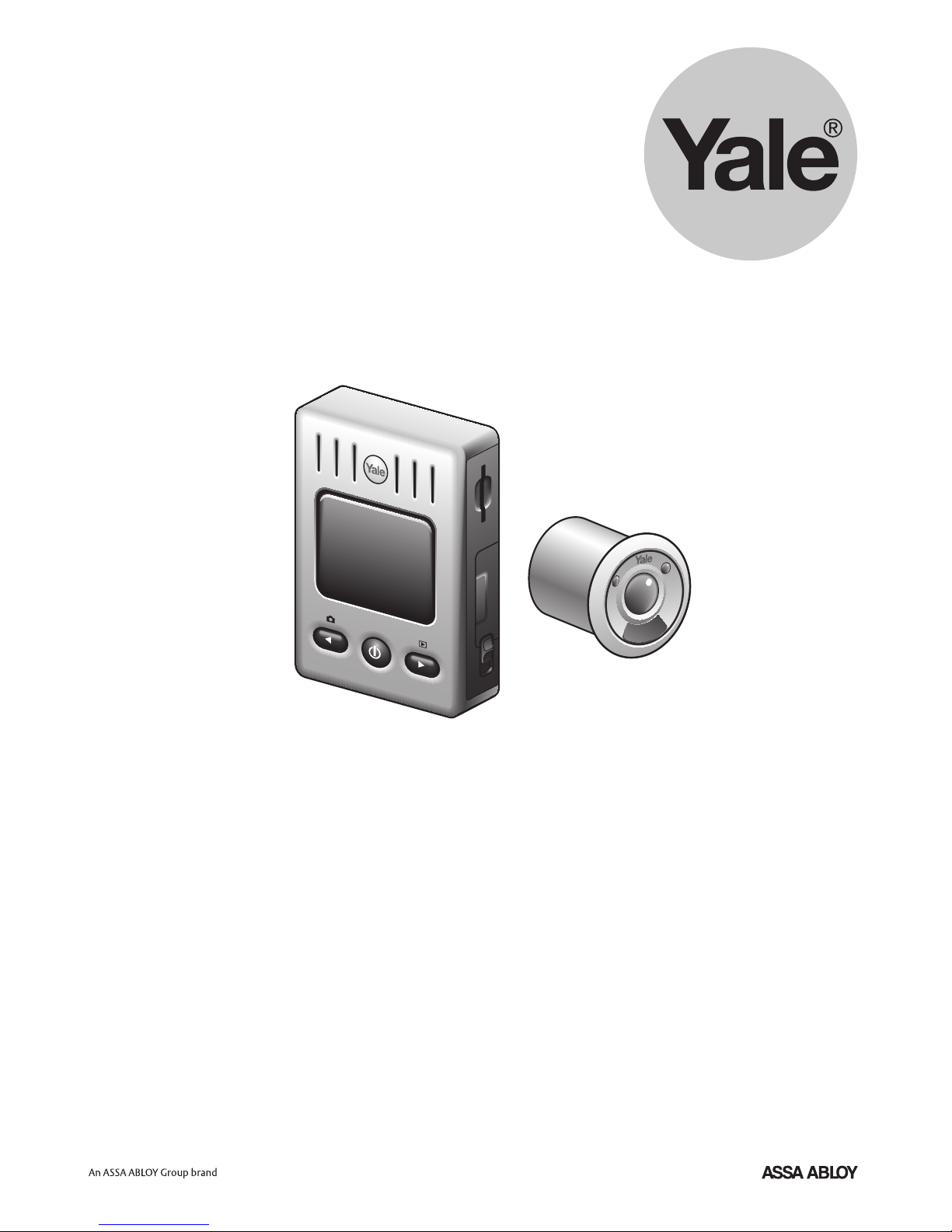
Electronic Door Viewer
User Manual
Keep this manual safe for future reference
EIS1100
Page 3
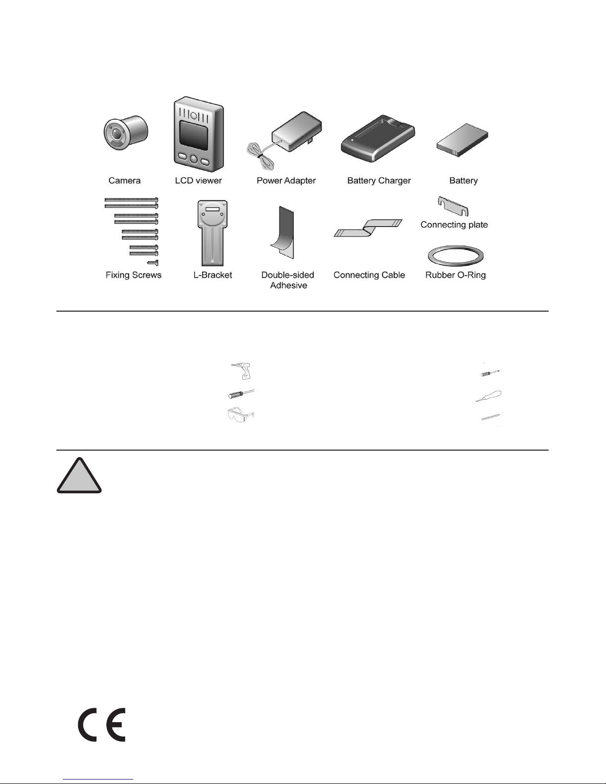
Pack Content
Safety Warnings & Advice
!
Please read these fitting instructions carefully before starting.
Take care when using power tools, follow the safety instructions provided with the tools.
Please correctly dispose of the packaging after fitting.
Battery Safety:
The Door viewer is powered by a Lithium-ion (Li-ion) rechargeable battery.
Only use the charger supplied with the battery.
Do not over charge the battery as you may shorten its life span.
If left unused a fully charged battery will discharge itself overtime.
Temperature extremes can affect the ability of your battery to charge.
Only use the battery and its charger for its intended uses.
Never use any charger or battery, which is damaged.
Do not short circuit the battery by directly connecting the ‘+’ and ‘-’ terminals.
Do not dispose of the battery in a fire.
Dispose of batteries according to your local regulations (e.g recycling).
Do not dispose of batteries in normal household waste.
Warning: This is a class A Product. In a domestic environment this product may cause radio
interferance in which case the user may be required to take adequate measures.
2
Tools Required:
Drill
32mm Drill bit
Safety glasses
Small crosshead screwdriver
Bradawl
Pencil
Page 4
Before Installation
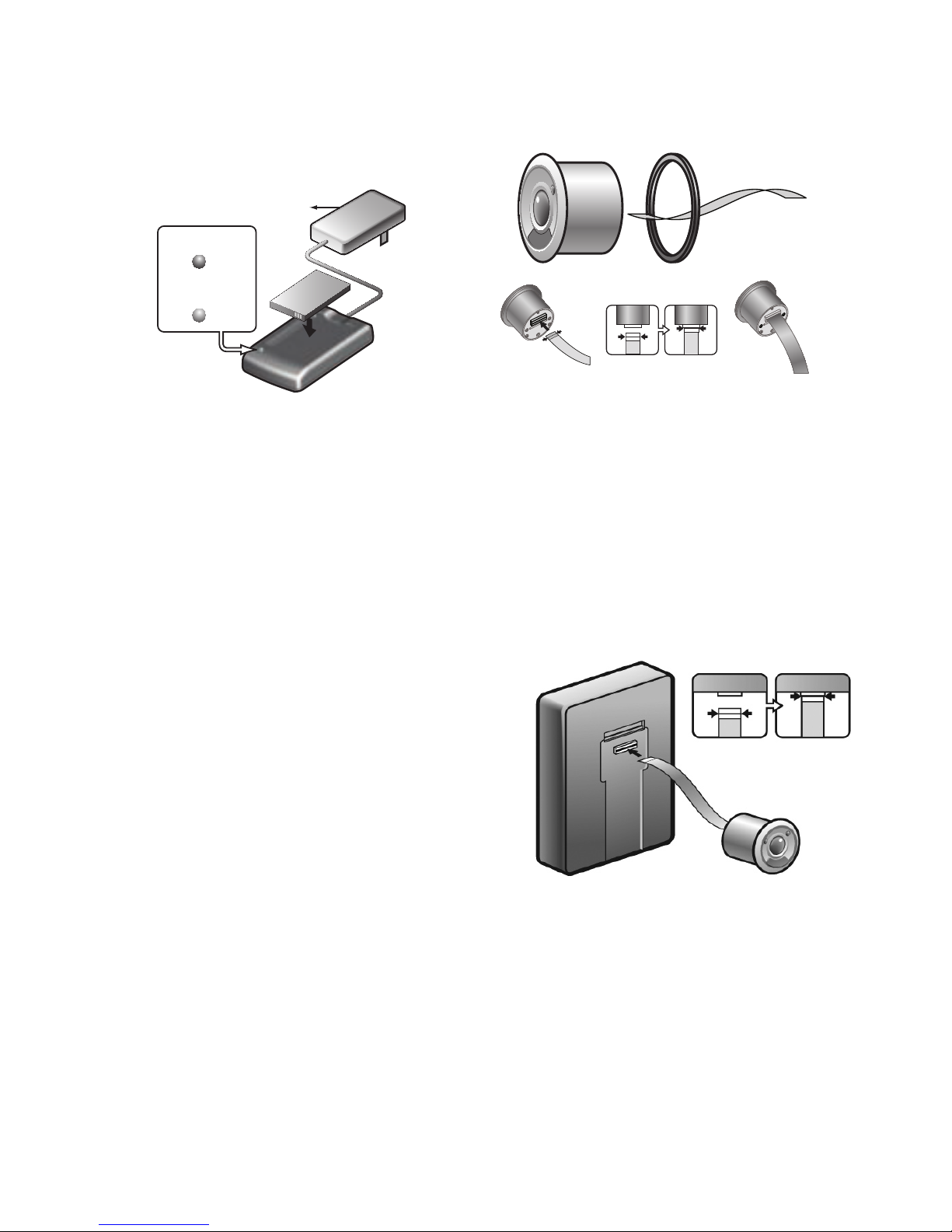
1. Charging the battery: The battery will
need to be fully charged before inserting
into the LCD viewer, this will take 1
1
⁄2 - 2
hours.
Plug the power adapter into the mains
power socket and insert the ‘pin’ plug into
the battery charger. Fit the battery into the
charger with label facing up.
The light will glow red when charging and
green when fully charged.
Note: the red light will blink if the battery is
not correctly inserted.
Battery Life: The battery will last about
400 to 500 snaps (photos) per charge
and can be recharged at least 200 times.
The battery have 6 months maximum
standby time.
2. Carefully insert the connecting cable
squarely into the back of the camera, blue
side up and in as far as the black line.
Important: The connecting cable is
fragile and should be handled with
care. Image will be distorted if cable not
connected properly.
3. Carefully insert the connecting cable
squarely into the back of the LCD viewer,
blue side up and in as far as the black
line.
Adapter
(Red)
(Green
)
Charging
Complet
e
3
Page 5

4. When the battery is fully charged, slide
down the catch on the right side of the LCD
viewer and open the battery cover. Insert the
battery with the label facing the door and the
flap on the right. Close the battery cover and
slide up the catch.
5. Press and hold down the ‘power button’ for
2 seconds, an image will appear plus date/
time information at the bottom of the screen.
6. Carefully remove the connecting cable from
the LCD viewer. The cable is left attached to
the camera.
The test is now complete.
Before Installation (continued)
4
Page 6

WARNING: DURING INSTALLATION
YOU WILL BE ASKED TO DRILL A 32mm
HOLE ON YOUR DOOR OF WHICH
IS PERMENANT AND IRREVERSIBLE.
SHOULD YOU NOT WISH THIS TO
HAPPEN PLEASE DO NOT PROCEED
WITH INSTALLATION. PLEASE BE
AWARE OF THIS CONSEQUENCE AS
WE CANNOT BE HELD LIABLE FOR ANY
DAMAGES RESULTING FROM DRILLING
THE DOOR.
Do not point camera in the direction of the
sun. Please note varying position of sun
throughout the year.
1. Decide on the position of the door
viewer on the door, the camera should be
high enough to see the face of the caller
outside and the LCD viewer at a suitable
height for viewing inside. Beware that if
the camera is fitted too high it might not
be possible to see below a certain height,
i.e. child visitor. If necessary, reconnect the
viewer to the camera so that the angle of
the camera can be observed (See previous
steps).
2. Using a suitable drill bit for your door,
drill a 32mm (1 ¼”) diameter hole, from
both sides of the door in the required
position.
Diy tip: Drill through the door until the
tip of the drill bit breaks through the other
side then finish by drilling through from the
other side of the door.
Important: If fitting to a plastic or reinforced
door, please check with the door
manufacturer before drilling the door.
3. Place the rubber O-ring over the
camera. The cable should have been
already inserted into the camera in
previous steps. If not, carefully insert the
connecting cable squarely into the back of
the camera, blue side up and in as far as
the black line.
4. Select and insert screws of a suitable
length (depending on the thickness of
the door) into the back of the camera
(4 lengths supplied). Test the camera in
the drilled hole to check that the screws
JUST reach through to the other side of
the door, try longer or shorter screws as
required. Remove the camera.
Installation instructions
5
Page 7

Installation instructions (continued)
5. Stick the twin adhesive tape to the
back of the L bracket. Remove the
adhesive backing. From inside stick the
L bracket in position over the drilled hole,
ensure it is straight.
From outside, insert the camera into the
hole (with ‘PRESS’ button at the bottom)
and carefully feed the connecting cable
and screws through the slot and the
holes in the L bracket. Hold the camera in
position.
6. From inside, place the connecting plate
over the screw heads and tighten the
screws onto the connecting plate. Tighten
so the camera does not move but do not
overtighten.
7. Carefully insert the connecting cable
squarely into the back of the LCD viewer,
blue side up and in as far as the black
line.
•
•
✔
6
Page 8

8. Hook the LCD viewer onto the
connecting plate (ensure the connecting
cable is not twisted), slide the viewer down
and fix in position from below using the
5mm (3/16”) screw.
9. If required insert an ‘SD card’ (not
supplied) into the slot above the battery
cover. To remove the ‘SD card’, push in,
release and then pull out.
SD cards are available from most electronic
and digital imaging retailers.
The fitting of your new Yale door viewer is
now complete.
Installation instructions (continued)
7
Page 9

Setting up the door viewer
1. All data will need to be set when the battery is
first fitted or when it is removed and re-fitted.
Press the left arrow button and hold down, then
press the power button and hold down both for
5 seconds, the MENU SETUP will appear.
Use the arrow buttons to scroll through the
subjects/settings, they will appear white as you
scroll, to select the subject press the power
button. When the selected items are white the
information can be changed using the left (up)
and right (down) buttons, use the power button
to move onto the next subject/setting.
Note: Sleep time refers to the length of time the
door viewer stays on once the power button is
pressed.
Set all of the subjects as required.
Note: If you do not ‘exit’ the menu the display
will stay on until either the battery is drained or
the door bell is pressed.
8
Page 10

Specification
2. Using the Viewer: When the door bell is pressed
the LCD screen will automatically operate (the length
of time this stays on can be changed in the menu).
To view without the bell being pressed, press the
power button for 2 seconds. Press the power button
again (while screen is on) and you will zoom in, press
the left or right arrow buttons to zoom to the left or
right. Press the power button again and to zoom
back out.
3. Taking Pictures: Only possible if a ‘SD card’ is
fitted (not supplied).
If required, each time the door bell is pressed a
picture will be taken (see the setup menu).
To take a picture without the door bell being
pressed, press the power button (if not on) then
press the left arrow button.
4. Playback (View) Pictures: To view the pictures,
press the power button (if not on) then press the
right arrow button. Use the left and right arrow but
tons to scroll through the pictures taken. You can
zoom into the photo by pressing power button and
then left/right to navigate.
Note: If untouched the door viewer will shut down in
10, 20 or 30 seconds depending on setting.
Using the viewer
Doorbell
Pressing
9
Page 11

Model: HSA3400
HSA3020
HSA3060
HSA3010
HSA3050
HSA3045
HSA3080
HSA3030
HSA3070
ASSA ABLOY Ltd.
School Street
Willenhall
West Midlands
England
WV13 3PW
EIS1100
Date: 22/01/08
On behalf of ASSA ABLOY Ltd.
ASSA ABLOY Ltd.
School Street, Willenhall
West Midlands
England, WV13 3PW
John Ward
Director
Model: HSA3400
HSA3020
HSA3060
HSA3010
HSA3050
HSA3045
HSA3080
HSA3030
HSA3070
EN55022:2006
EN55024:1998+A1:2001+A2:2003
EN60950-1:2001+A11:2004
10
Page 12

 Loading...