


GLP20LX

GLP20LX, GLP25LX, GDP20LX, GDP25LX (B974)
SERVICE MANUAL CONTENTS
SECTION
PART
NUMBER
YRM
NUMBER
REV
DATE
FRAME............................................................................................................................ 550109110 0100 YRM 1766 12/14
YANMAR DIESEL ENGINES.......................................................................................... 524240453 0600 YRM 1205 12/14
PSI 2.4L ENGINE............................................................................................................ 550108890 0600 YRM 1755 12/14
COOLING SYSTEM........................................................................................................ 550109111 0700 YRM 1767 12/14
FUEL SYSTEM PSI 2.4L................................................................................................ 550108892 0900 YRM 1757 12/14
SINGLE SPEED PS CHAIN DRIVE PTO........................................................................ 550108495 1300 YRM 1740 12/14
DRIVE AXLE AND DIFFERENTIAL ASSEMBLY REPAIR............................................ 550109112 1400 YRM 1768 12/14
STEERING AXLE REPAIR............................................................................................. 550109113 1600 YRM 1769 12/14
BRAKE SYSTEM............................................................................................................ 550108498 1800 YRM 1743 12/14
HYDRAULIC CLEANLINESS PROCEDURES............................................................... 550073240 1900 YRM 1620 12/14
HYDRAULIC GEAR PUMPS.......................................................................................... 550108499 1900 YRM 1744 12/14
MAIN CONTROL VALVE................................................................................................ 550108500 2000 YRM 1745 12/14
CYLINDER REPAIR (MAST S/N A698 AND A699)....................................................... 550109114 2100 YRM 1770 12/14
WIRE HARNESS REPAIR.............................................................................................. 524223769 2200 YRM 1128 12/14
ELECTRICAL SYSTEM.................................................................................................. 550109115 2200 YRM 1771 12/14
ENGINE ELECTRICAL SYSTEM, PSI 2.4L ENGINE..................................................... 550109116 2200 YRM 1772 12/14
MAST REPAIR (S/N A698 AND A699)........................................................................... 550109117 4000 YRM 1773 12/14
METRIC AND INCH (SAE) FASTENERS....................................................................... 524150797 8000 YRM 0231 10/13
PERIODIC MAINTENANCE............................................................................................ 550109197 8000 YRM 1774 12/14
CAPACITIES AND SPECIFICATIONS........................................................................... 550109119 8000 YRM 1775 12/14
DIAGRAMS AND SCHEMATICS.................................................................................... 550109120 8000 YRM 1776 12/14
DIAGNOSTIC TROUBLESHOOTING MANUAL............................................................ 550022929 9000 YRM 1434 12/14
PART NO. 550109188 (12/14)

General
WARNING
The lift truck must be put on blocks for some
types of maintenance and repairs. The removal of
the following assemblies will cause large changes
in the center of gravity: mast, drive axle, engine
and transmission, and counterweight. When the
lift truck is put on blocks, put additional blocks in
the following positions to maintain stability:
• Before removing the mast and drive axle,
put blocks under the counterweight so the
lift truck cannot fall backward.
• Before removing the counterweight, put
blocks under the mast assembly so the lift
truck cannot fall forward.
The surface must be solid, even, and level when
the lift truck is put on blocks. Make sure that any
blocks used to support the lift truck are solid,
one-piece units. See the Operating Manual or the
Periodic Maintenance 8000YRM1774.
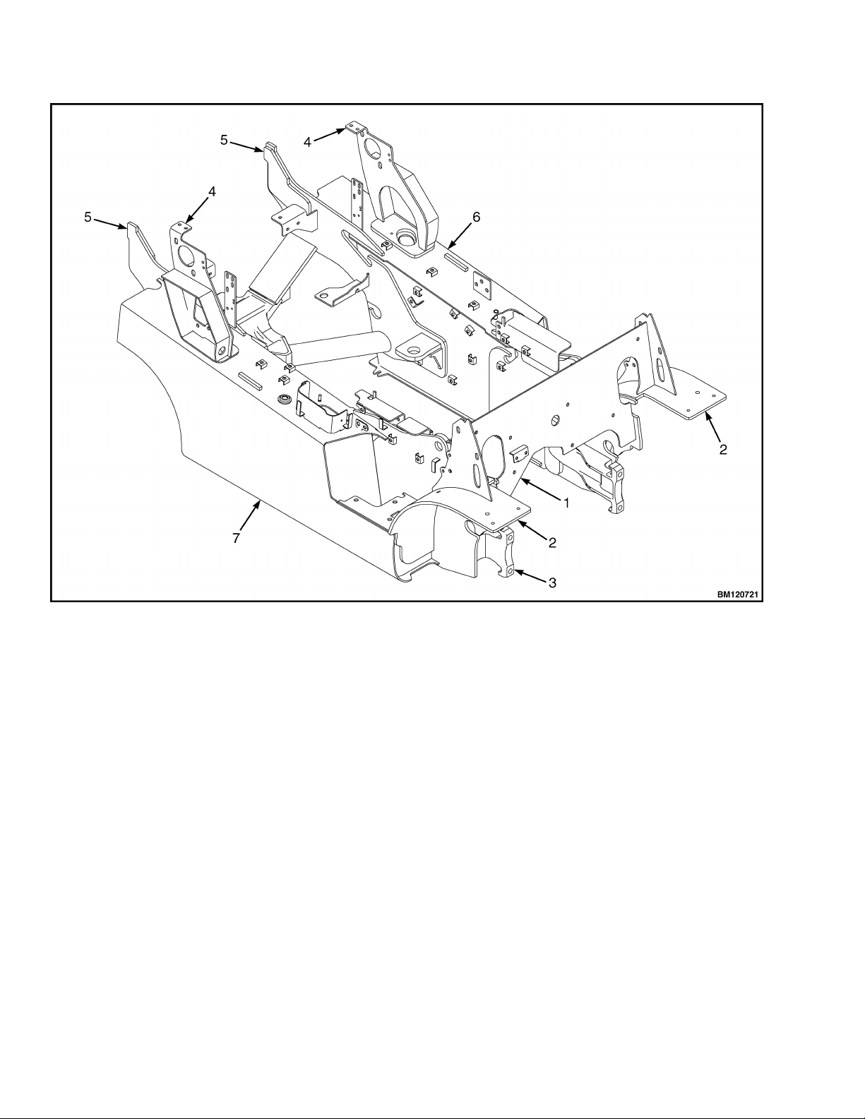
This section contains the description of the frame (see
Figure 1 and Figure 2) and connected parts.
Procedures for removing and installing the
counterweight, hood, overhead guard, engine, and
cooling system are found in this section. Checks for
the operator restraint system, adjustments for the
throttle pedal stop, and procedures for the repair of
tanks and installation of safety labels are also
included.
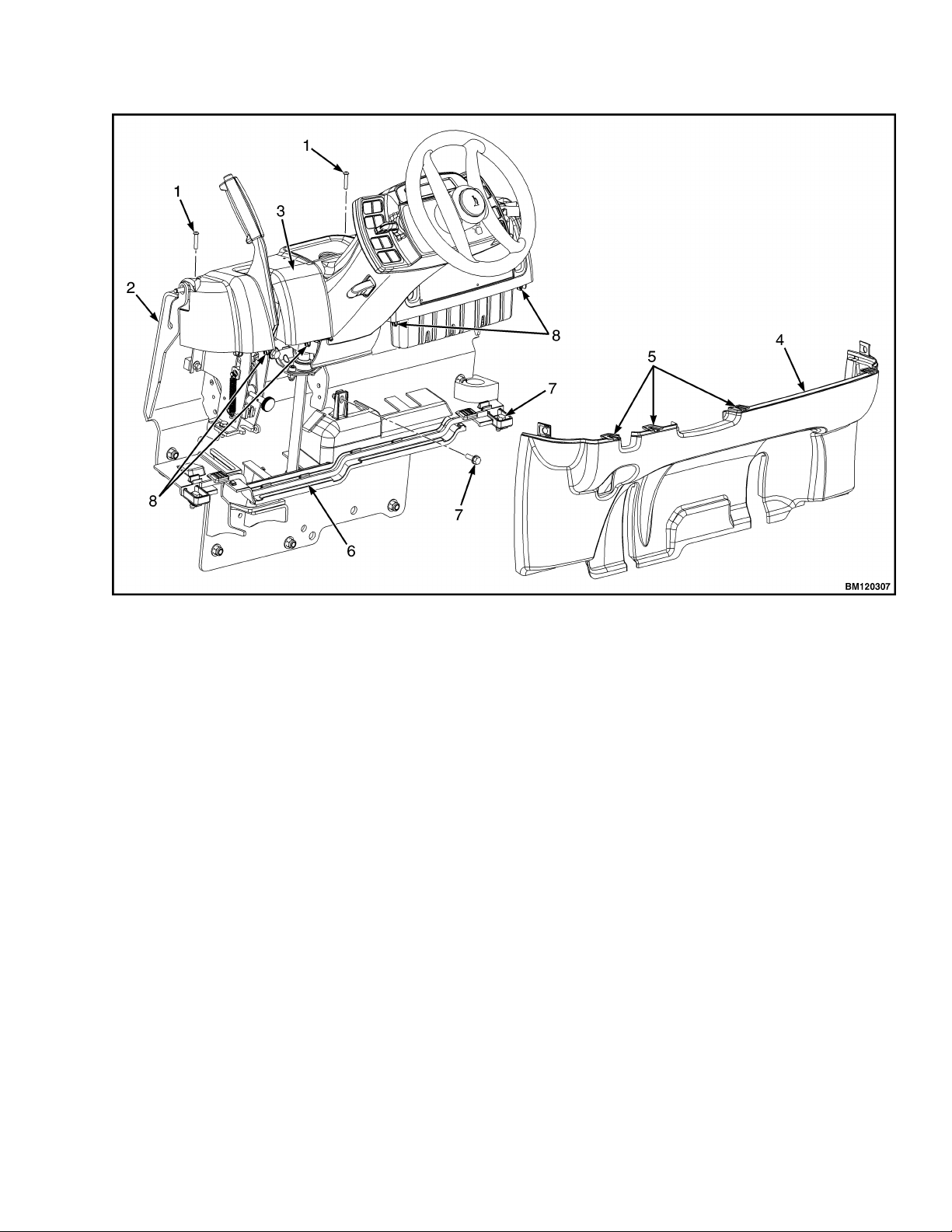
1. COWL PLATE
2. FENDER
3. FRAME
4. HOOD MOUNT
5. COUNTERWEIGHT SUPPORT
6. LEFT-HAND FRAME WELDMENT
7. HYDRAULIC TANK
Figure 1. Frame, LPG
0100 YRM 1766 General
1
1. COWL PLATE
2. FENDER
3. FRAME
4. HOOD MOUNT
5. COUNTERWIEGHT SUPPORT
6. FUEL TANK
7. HYDRAULIC TANK
Figure 2. Frame, Dual Fuel or Diesel
General 0100 YRM 1766
2
Hood, Seat, and Side Covers Replacement
REMOVE
1. Slide the seat to the closest position to the steer-
ing column.
2. Fully tilt the steering column forward.
NOTE: Perform Step 3 for lift trucks equipped with
LPG.
3. Swing LPG tank off to side. See Fuel System PSI
2.4L 0900YRM1757 for procedures.
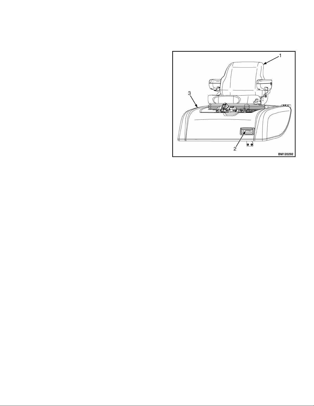
4. Raise the hood latch on the left, front corner of
the hood to unlatch and lift up the hood. See Fig-
ure 3.
5. Remove the floor mat and floor plate. See Fig-
ure 4.
6. Remove the two capscrews holding the left and
right rear side covers to the frame. Remove the
rear side covers from the frame. See Figure 4.
1. HOOD LATCH
2. SEAT
3. HOOD
Figure 3. Hood Latch
0100 YRM 1766 Hood, Seat, and Side Covers Replacement
3
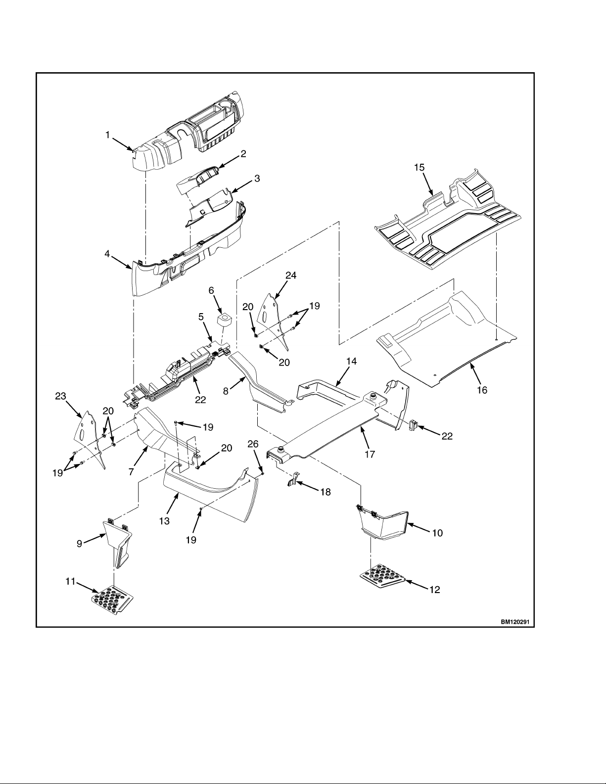
Figure 4. Side Cover, Floor Plate, and Cowl Components
Hood, Seat, and Side Covers Replacement 0100 YRM 1766
4

Legend for Figure 4
1. DASH ASSEMBLY
2. UPPER STEERING COLUMN COVER
3. LOWER STEERING COLUMN COVER
4. KICK PANEL
5. PLATE ASSEMBLY
6. GROMMET
7. LEFT FRONT SIDE COVER
8. RIGHT FRONT SIDE COVER
9. LEFT STEP PANEL
10. RIGHT STEP PANEL
11. LEFT STEP PLATE
12. RIGHT STEP PLATE
13. LEFT REAR SIDE COVER
14. RIGHT REAR SIDE COVER
15. FLOOR MAT
16. FLOOR PLATE
17. RADIATOR COVER
18. SEALS
19. CAPSCREW
20. CLIP NUT
21. INSERT
22. PLATE ASSEMBLY SEAL
23. LEFT COWL PLATE
24. RIGHT COWL PLATE
0100 YRM 1766 Hood, Seat, and Side Covers Replacement
5
7. Remove the four capscrews and clip nuts holding
the left and right front side covers and left and
right cowl plates to the frame. Remove front side
covers and cowl plates.
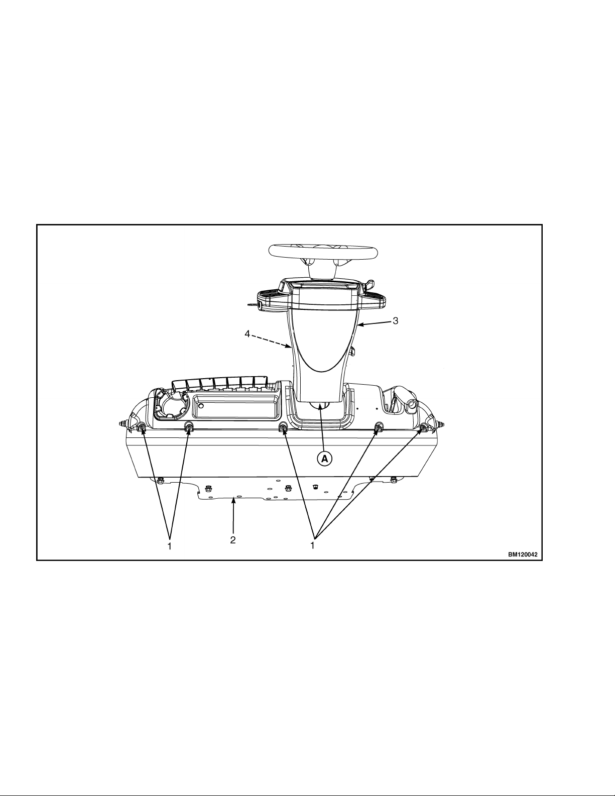
8. Fully lower the steering column.
9. Remove upper steering column cover by pulling
up on the base of the upper steering column
cover to release the latches (one on either side),
and pulling cover away from steering column. See
Figure 5.
10. Remove the five Allen Head screws (see Fig-
ure 5) securing the dash to top of cowl.
11. Pull kick panel up from bottom and out to remove
kick panel from seal plate and clips on dash
panel.
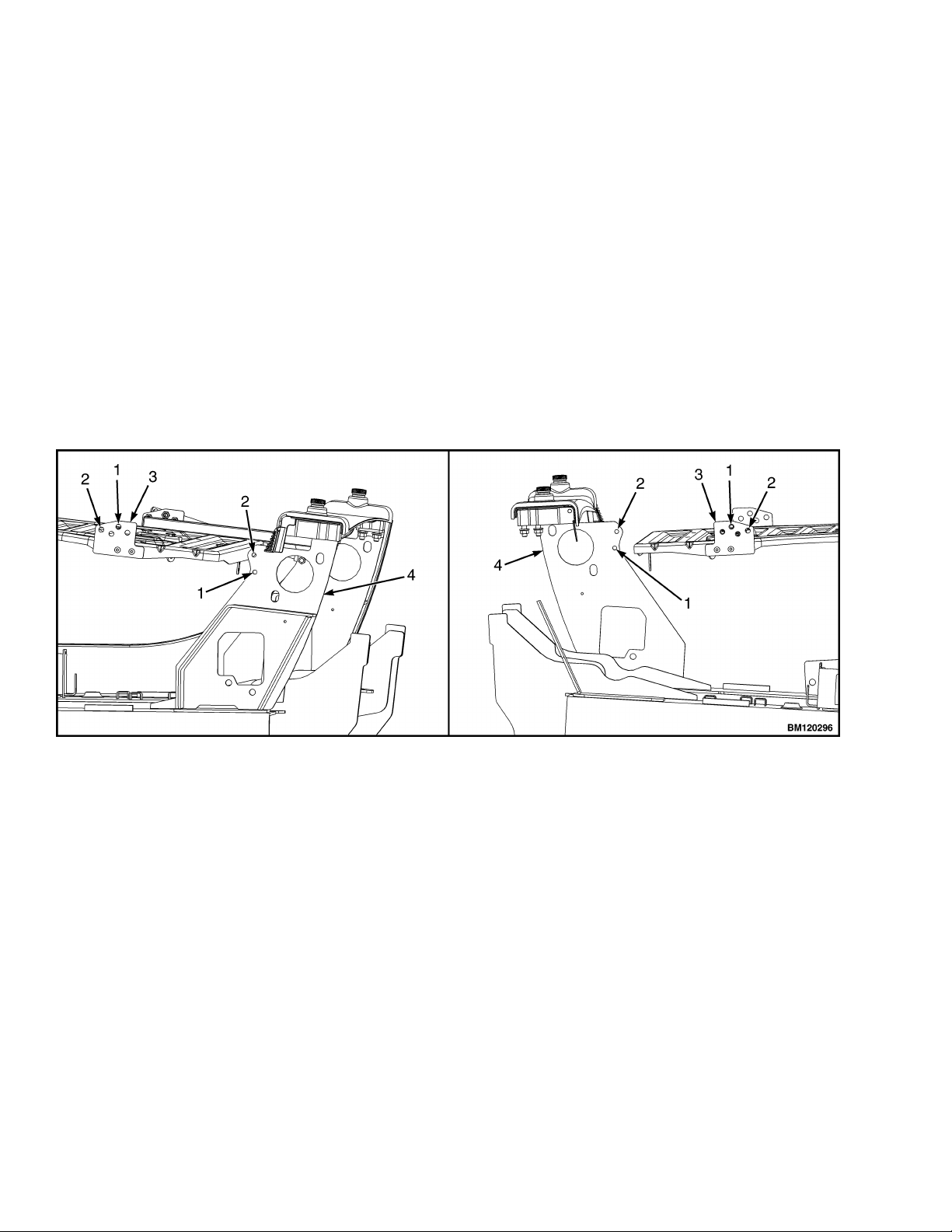
12. Remove dash panel from cowl. See Figure 6.
13. Remove three capscrews holding the seal plate.
Remove seal plate. See Figure 6.
NOTE: TOP VIEW OF DASH PANEL SHOWN
A. INDICATES TO PULL UP TO UNLATCH
1. ALLEN HEAD SCREWS
2. COWL
3. UPPER STEERING COLUMN COVER
4. LOWER STEERING COLUMN COVER
Figure 5. Dash Panel and Upper Steering Column Cover Removal
Hood, Seat, and Side Covers Replacement 0100 YRM 1766
6
1. ALLEN HEAD SCREWS
2. COWL
3. DASH PANEL
4. KICK PANEL
5. KICK PANEL NOTCHES
6. SEAL PLATE
7. CAPSCREWS
8. CLIPS
Figure 6. Dash Panel, Kick Panel, and Seal Plate Removal
0100 YRM 1766 Hood, Seat, and Side Covers Replacement
7
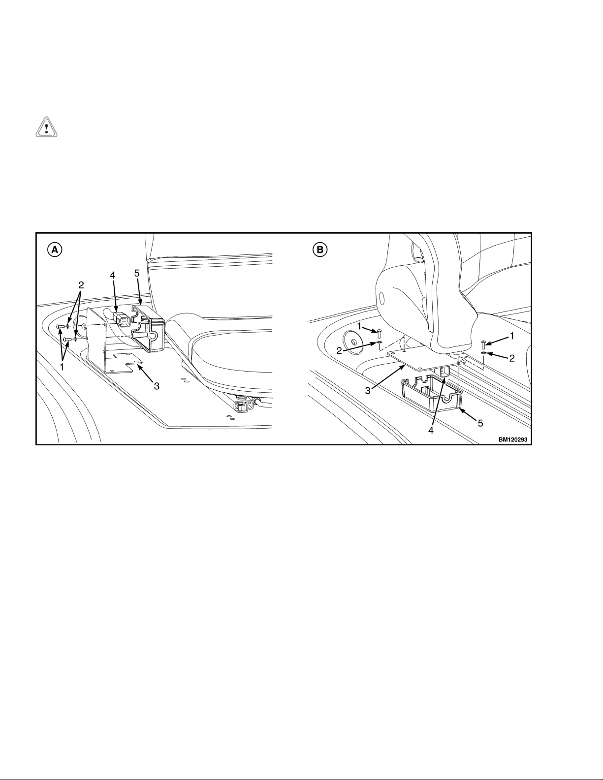
14. Remove two capscrews and washers from cover
plate and remove electrical cover. Disconnect
seat harness from chassis harness. See Figure 7.
CAUTION
When removing the seat from the hood, do not
use an impact wrench to remove the capscrews.
Damage can be caused to the threads on the cap-
screws and in the holes.
15. Open hood and pull chassis harness through hole
in hood. See Figure 8.
Remove the four capscrews and nuts holding the
seat to the hood. Lift the seat off the hood. See
Figure 8. Close hood.
16. Remove the nuts from ball studs on gas springs.
Remove gas springs from the hood. See Figure 9.
17. Remove the hinge capscrews and nuts, located in
the rear of the hood. See Figure 9.
18. Lift the hood from the truck.
A. NON-SUSPENSION SEAT B. FULL SUSPENSION SEAT
1. CAPSCREWS
2. WASHER
3. COVER PLATE
4. ELECTRICAL CONNECTOR (SEAT HARNESS)
5. ELECTRICAL COVER
Figure 7. Disconnect Seat Wire Harness
Hood, Seat, and Side Covers Replacement 0100 YRM 1766
8
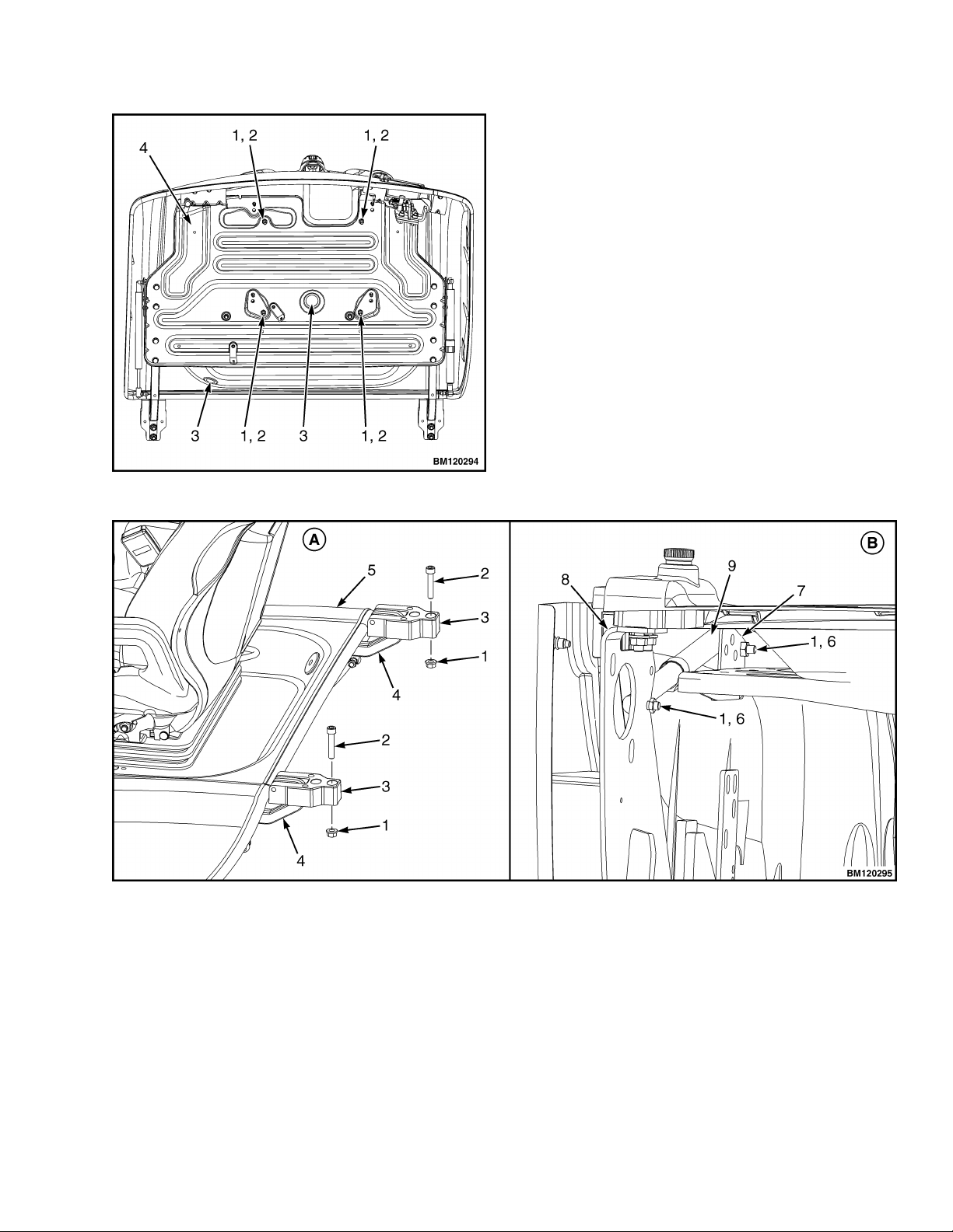
Figure 8. Remove Seat From Hood
Legend for Figure 8
NOTE: MOUNTING HOLES FOR FULL SUSPEN-
SION SEAT SHOWN. MOUNTING HOLES FOR
NON-SUSPENSION SEAT ARE THE SAME.
1. CAPSCREW
2. NUT
3. HOLE FOR CHASSIS HARNESS
4. HOOD LINER
A. HOOD HINGE ARRANGEMENT B. GAS SPRING ARRANGEMENT (LEFT SIDE
SHOWN)
1. NUT
2. CAPSCREW
3. HOOD HINGE MOUNT
4. HOOD HINGE ARM
5. HOOD
6. BALL STUD
7. GAS SPRING MOUNTING BRACKET
8. HOOD MOUNT
9. GAS SPRING
Figure 9. Gas Spring and Hood Removal
0100 YRM 1766 Hood, Seat, and Side Covers Replacement
9
INSTALL
1. Place the hood onto the lift truck frame.
2. Install the hood hinge mount screws and nuts, lo-
cated in the rear of the hood, and tighten to
38 N•m (28 lbf ft). See Figure 9.
3. Align the ball studs in the gas springs with holes
in the gas spring mounting bracket and hood
mount. See Figure 10 for holes to use depending
on type of seat being installed. Install nuts on ball
studs to attach gas springs to the hood. Tighten
nuts to 19.2 N•m (170 lbf in).
4. Install latch striker in highest slot position. Check
that latch striker is in center of jaws of hood latch
when hood closes. Open and close the hood to
ensure that the center pin strikes the hood latch
properly and that the stop screw contacts the
frame. A properly closed hood MUST click twice
on the hood latch. If the hood latch does not close
properly, loosen the capscrews on the back of the
center pin and adjust the center pin up or down as
required for correct alignment. See Figure 11.
5. Push down until hood just touches rubber
bumper. Make sure latch striker is still in center of
hood latch. Open hood and tighten capscrews for
latch.
6. Check operation of hood latch. Have an operator
sit in the seat. Make sure hood is fully closed (two
clicks). Also check that hood touches rubber
bumper. If necessary, repeat Step 4 and Step 5.
A. LEFT SIDE B. RIGHT SIDE
1. FULL SUSPENSION SEAT
2. NON-SUSPENSION SEAT
3. GAS SPRING MOUNTING BRACKET
4. HOOD MOUNT
Figure 10. Gas Spring and Seat Hole Alignment
Hood, Seat, and Side Covers Replacement 0100 YRM 1766
10
1. HOOD
2. HOOD LATCH
3. CENTER PIN
4. CAPSCREW
Figure 11. Hood Latch Adjustment
CAUTION
When installing the seat to the hood, do not use
an impact wrench to install the capscrews. Dam-
age can be caused to the threads on the screws
and in the holes.
7. Place the seat on the hood and thread the chas-
sis harness through the holes in the hood. See
Figure 8.
8. Align the holes in the seat with the holes in the
hood. See Figure 8. Insert capscrews and nuts.
Tighten capscrews to 18 N•m (159 lbf in).
9. Connect seat harness to chassis harness. Install
cover plate to electrical cover using two cap-
screws and washers. See Figure 7.
10. Using three capscrews, install seal plate. See Fig-
ure 6. Tighten capscrews to
10.8 N•m (95.6 lbf in).
11. Place dash panel on cowl and secure dash panel
to cowl using five Allen Head screws. Tighten Al-
len Head screws to 3.5 N•m (31 lbf in). See Fig-
ure 5.
12. Align notches on kick panel to clips on dash panel
and push kick panel into place on seal plate. See
Figure 6.
13. Raise steering column to highest position and in-
stall upper steering column cover by aligning the
two latches and pushing down until latched. See
Figure 5.
14. Using four capscrews and clip nuts, install the left
and right front side covers and left and right cowl
plates to the frame. See Figure 4.
15. Using two capscrews, install the left and right rear
side covers to the frame. See Figure 4.
16. Install the floor mat and floor plate.
NOTE: Perform Step 17 for lift trucks equipped with
LPG.
17. Swing the LPG tank into position on back of coun-
terweight. See Fuel System PSI 2.4L
0900YRM1757 for procedures.
18. Adjust the steering column and seat positions.
0100 YRM 1766 Hood, Seat, and Side Covers Replacement
11

Steering Column
DESCRIPTION
This section describes the repair procedures for the
steering column. The Steering Column Assembly
mounts to the cowl inside the operator compartment
and is the mechanical connection between the steer-
ing wheel and the steering control unit. The steering
column includes the steering wheel, housing, bracket
and lower shaft. For lift trucks with gas and LPG en-
gines, bolts and bushings attach the steering column
to the cowl standoffs. For lift trucks with diesel en-
gines, bolts, bushings and isolators attach the steer-
ing column to the cowl standoffs See Figure 12.
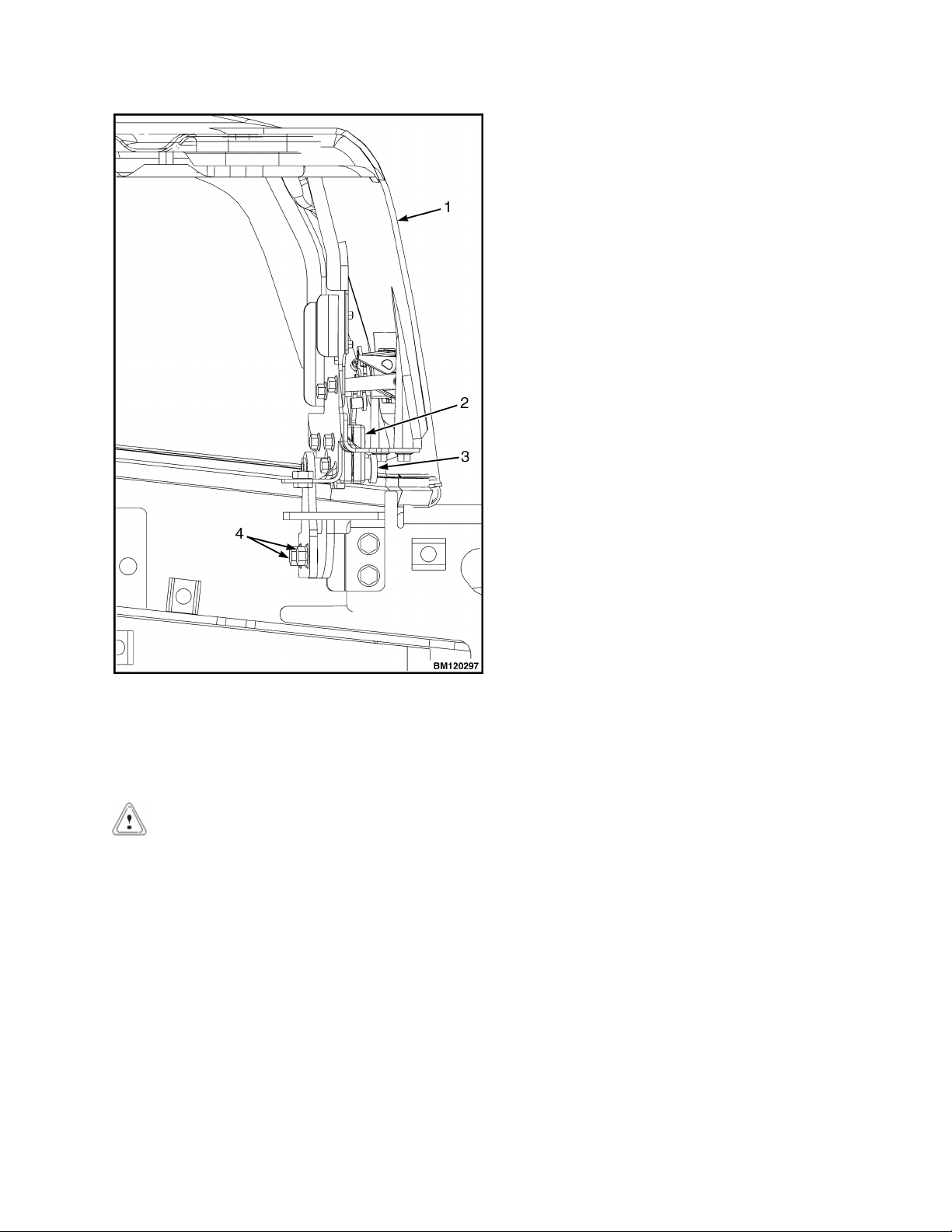
NOTE: DIESEL SHOWN, LPG AND BI-FUEL SIMI-
LAR.
1. STEERING WHEEL
2. STEERING COLUMN
3. COWL
Figure 12. Steering Column and Cowl
STEERING COLUMN REPAIR
Remove
1. Put blocks on each side (front and back) of tires
to prevent lift truck from moving.
CAUTION
Disconnect the negative battery cable on internal
combustion trucks. Disconnect the battery before
removing any covers.
2. Attach a tag on the battery connector or negative
battery cable stating, DO NOT CONNECT BAT-
TERY. Move the steering column to the most
FORWARD position.
CAUTION
If a puller tool is used to remove steering wheel
from steering column, be careful not to damage
horn wires.
NOTE: This procedure is for the removal of all com-
ponents of the steering column assembly. All compo-
nents are not often removed for a repair procedure.
Do only those steps of the procedure necessary to re-
move the required component.
NOTE: Tag wires prior to disconnect
3. Remove the horn button assembly and discon-
nect electrical wires. Remove large hex nut and
steering wheel from steering column. See Fig-
ure 13.
1. HORN BUTTON
2. HEX NUT
3. STEERING WHEEL
4. STEERING COLUMN
Figure 13. Steering Wheel Remove/Install
Steering Column 0100 YRM 1766
12
4. Remove steering column covers. Remove floor
mats and floor plate. See section Hood, Seat, and
Side Covers Replacement.
NOTE: Perform Step 5 for lift trucks equipped with bi-
fuel or LPG engines.
5. Remove four capscrews, four bushings and steer-
ing column from cowl standoffs. See Figure 14.
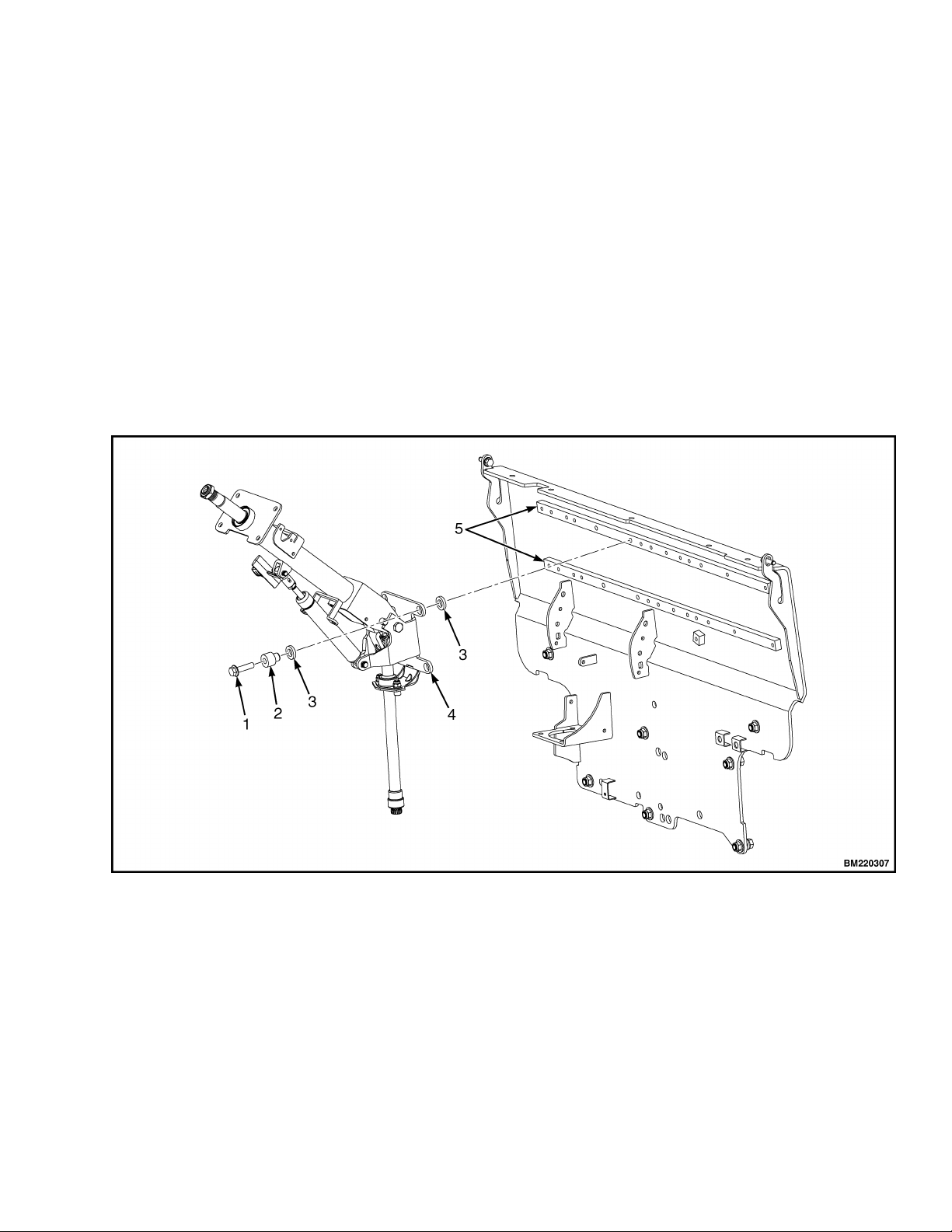
NOTE: Perform Step 6 for lift trucks equipped with
diesel engines.
6. Remove four capscrews, four bushings, four iso-
lators, steering column and four isolators from
cowl standoffs. See Figure 14.
Disassemble
NOTE: Remove and discard snap rings if installed.
1. Remove two pins and gas spring from housing.
See Figure 15.
2. Remove two pivot bolts, two bushings, two nuts
and bracket from housing.
3. Remove split pin and lower shaft from upper
shaft.
4. Remove connector from connector bracket. Re-
move connector bracket, fastener, four screws
and two horn contacts from housing.
NOTE: DIESEL SHOWN, LPG AND GAS SIMILAR.
1. CAPSCREW
2. BUSHING
3. ISOLATOR
4. STEERING COLUMN
5. COWL STANDOFF
Figure 14. Steering Column Remove/Install
0100 YRM 1766 Steering Column
13

Clean
WARNING
Cleaning solvents can be flammable and toxic and
can cause skin irritation. When using cleaning
solvents, always follow the solvent manufactur-
er's recommended safety precautions.
WARNING
Compressed air is used for cleaning and drying
purposes, or for cleaning restrictions. wear pro-
tective clothing (goggles/shields, gloves, etc.).
Make sure the path of the compressed air is away
from all personnel to avoid injury.
1. Clean metal parts in solvent. Remove all traces of
old lubricant and dirt. Clean nonmetal parts with
warm soapy water and a lint free cloth.
2. After cleaning dry parts with compressed air. DO
NOT dry parts with a cloth.
Inspect
1. Inspect for loose, burned, missing, cracked or
damaged hardware.
2. Inspect all parts for dents, holes, bends, burrs,
rust, corrosion or marred finishes.
3. Replace all defective or damaged parts.
Assemble
NOTE: This procedure is for the installation of all
components of the steering column assembly. All
components are not often removed for a repair proce-
dure. Do only those steps of the procedure necessary
to install the required component.
NOTE: Perform Step 1 only for lift trucks manufac-
tured before January, 2012.
1. Lubricate the horn contact slip rings with a small
amount of conductive grease Yale P/N
582014302. See Figure 15.
2. Install fastener, connector bracket and connector,
two horn contacts and four screws.
3. Assemble lower shaft and upper shaft, secure
with spit pin.
4. Install two pivot bolts, two bushings, two nuts and
bracket onto housing.
5. Install gas spring and two pins on housing.
Install
NOTE: Lubricate spline end of lower shaft with multi
purpose grease, see Periodic Maintenance Manual
for your lift truck.
NOTE: Perform Step 1 for lift trucks equipped with
gas or LPG engines.
1. Install steering column, four bushings and four
bolts on cowl standoffs. Tighten bolts to
38 N•m (28 lbf ft). See Figure 14.
NOTE: Perform Step 2 for lift trucks equipped with
diesel engines.
2. Install four isolators, steering column four isola-
tors, four bushings and four bolts standoffs on
cowl. Tighten bolts to 38 N•m (28 lbf ft). See Fig-
ure 14.
3. Install floor plate, floor mats and steering column
covers. See section Hood, Seat, and Side Covers
Replacement.
4. Install steering wheel and hex nut on steering col-
umn. Tighten hex nut to 40 to 54 N•m (30 to
40 lbf ft). Connect electrical wiring and install horn
button. See Figure 13.
5. Remove tag from negative battery connector and
connect to battery. Adjust steering column to neu-
tral position.
6. Remove blocks from each side of tires.
Steering Column 0100 YRM 1766
14
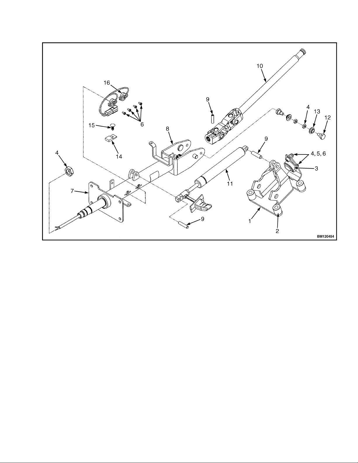
1. BRACKET
2. SPACER
3. JOINT
4. NUT
5. WASHER
6. SCREW
7. UPPER SHAFT
8. HOUSING
9. PIN
10. LOWER SHAFT
11. GAS SPRING
12. BOLT
13. BUSHING
14. CONNECTOR
15. FASTENER
16. HORN CONTACT
Figure 15. Steering Column Assembly
0100 YRM 1766 Steering Column
15
Counterweight Replacement
REMOVE
WARNING
The lift truck must be put on blocks for some
types of maintenance and repair. The removal of
the following assemblies will cause large changes
in the center of gravity: mast, drive axle, engine
and transmission, and counterweight. When the
lift truck is put on blocks, put additional blocks in
the following positions to maintain stability:
• Before removing the mast and drive axle,
put blocks under the counterweight so the
lift truck cannot fall backward.
• Before removing the counterweight, put
blocks under the mast assembly so the lift
truck cannot fall forward.
The surface must be solid, even, and level when
the lift truck is put on blocks. Make sure that any
blocks used to support the lift truck are solid,
one-piece units. See the Operating Manual or Peri-
odic Maintenance 8000YRM1774.
WARNING
DO NOT operate the lift truck if the capscrew for
the counterweight is not installed. When the cap-
screw is removed, the counterweight can fall from
the lift truck.
WARNING
LPG can cause an explosion. DO NOT cause
sparks or permit flammable material near the LPG
system. LPG fuel systems can be disconnected
indoors only if the lift truck is at least 8 m (26 ft)
from any open flame, motor vehicles, electrical
equipment, or ignition source.
Close the shutoff valve on the LPG tank before
any part of the engine fuel system is disconnec-
ted. Run the engine until the fuel in the system is
used and the engine stops.
If the engine will not run, close the shutoff valve
on the LPG tank. Loosen the fitting on the supply
hose from the LPG tank where it enters the filter
unit. Permit the pressure in the fuel system to de-
crease slowly. Fuel leaving the fitting removes
heat. Use a cloth to protect your hands from the
cold fitting.
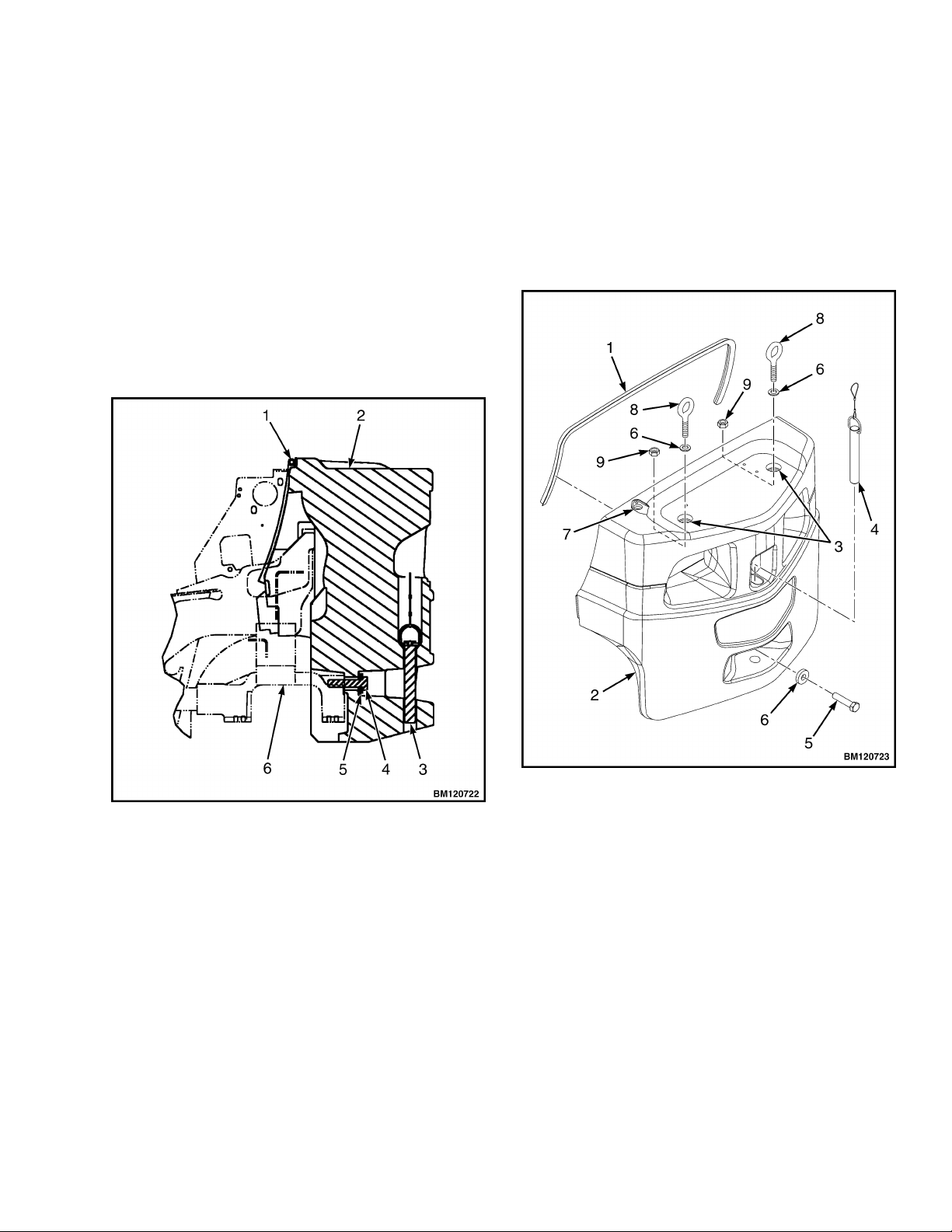
NOTE: The counterweight is held in position on the
frame by two hooks that are part of the frame. One
M24 × 3 × 110 capscrew holds the counterweight to
the lower part of the frame on lift truck models See
Figure 16.
NOTE: Perform Step 1 for lift trucks equipped with
LPG.
1. Use the procedures in Fuel System PSI 2.4L
0900YRM1757 to remove the LPG tank and
bracket so that the counterweight can be re-
moved.
Additional information on the LPG fuel system can
be found in Fuel System PSI 2.4L 0900YRM1757.
WARNING
The counterweight is heavy. Make sure that the
eyebolts and lifting devices have enough capacity
to lift the weight. The approximate weights of the
counterweight castings are shown in Table 1.
2. Install washers, lifting eyebolts, and nuts into lift
holes of the counterweight. See Figure 17. Con-
nect a crane to the lifting eyebolts and raise the
crane until it holds part of the weight of the coun-
terweight.
3. Remove the tow pin from counterweight.
4. Remove the capscrew from counterweight and
frame. See Figure 16 and Figure 17. Use the
crane to lift the counterweight from the lift truck.
Put counterweight on the floor so that it has stabil-
ity and will not fall over. Take care not to damage
exhaust or cooling system components.
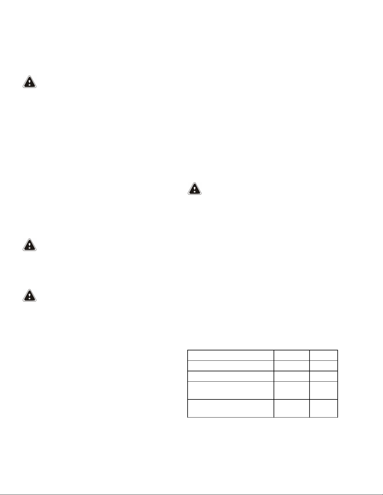
Table 1. Weight of Counterweights
Model kg lb
GLC050LX (B967) 1401 3088
GLP/GDP20LX (B974) 950 2094
GLP/GDP25LX (GLP/
GDP050LX) (B974)
1230 2712
GLP/GDP25LX (GLP/
GDP050LX) (B974)
1335 2943
Counterweight Replacement 0100 YRM 1766
16
INSTALL
1. Make sure the seals are on the counterweight. If
lifting eyebolts were removed from counterweight,
install washers, lifting eyebolts, and nuts into lift
holes on counterweight. See Figure 17.
2. Connect a crane to the lifting eyebolts and place
counterweight in position on lift truck frame. Make
sure hooks on frame fully engage counterweight
so it is aligned with the frame.
3. Install capscrew onto counterweight and frame.
See Figure 16 and Figure 17. Tighten capscrew
to 555 N•m (409 lbf ft).
1. SEAL
2. COUNTERWEIGHT
3. TOW PIN
4. CAPSCREW
5. WASHER
6. FRAME
Figure 16. Counterweight Installation
4. Install tow pin onto counterweight.
NOTE: Perform Step 5 for lift trucks equipped with
LPG.
5. Use the procedures in Fuel System PSI 2.4L
0900YRM1757 to install the LPG tank and
bracket after the counterweight has been instal-
led.
1. SEAL
2. COUNTERWEIGHT
3. LIFT HOLE
4. TOW PIN
5. CAPSCREW
6. WASHER
7. LPG ACCESS HOLE
8. LIFTING EYEBOLT
9. NUT
Figure 17. Counterweight With Lifting Eyebolts
0100 YRM 1766 Counterweight Replacement
17
Overhead Guard Replacement
REMOVE
WARNING
DO NOT operate the lift truck without the over-
head guard correctly fastened to the lift truck.
WARNING
DO NOT weld mounts for lights or accessories to
legs of the overhead guard. Changes that are
made by welding, or by drilling holes that are too
big or in the wrong location, can reduce the
strength of the overhead guard.
See your dealer for Yale lift trucks BEFORE per-
forming any changes to the overhead guard.
NOTE: The lifting device can be connected to any
number of positions on the overhead guard depend-
ing upon the lifting device available. The ideal choices
are a four point sling connected to all four corners on
the top of the overhead guard, or a two point sling
connected to two opposite corners of the overhead
guard. If a single point hoist is used, make sure that
the lift point is as close to the center of the overhead
guard as possible. If during the initial start of the lift,
the overhead guard is off balance, lower immediately
and move the hoist to a more centered point.
No welding or drilling on legs of overhead guard is
permitted as per previous WARNING.
1. Connect a lifting device to overhead guard.
NOTE: Note routing of electrical wires prior to discon-
necting. Tag electrical connectors during removal to
aid in installation.
2. Disconnect wires between frame and overhead
guard.
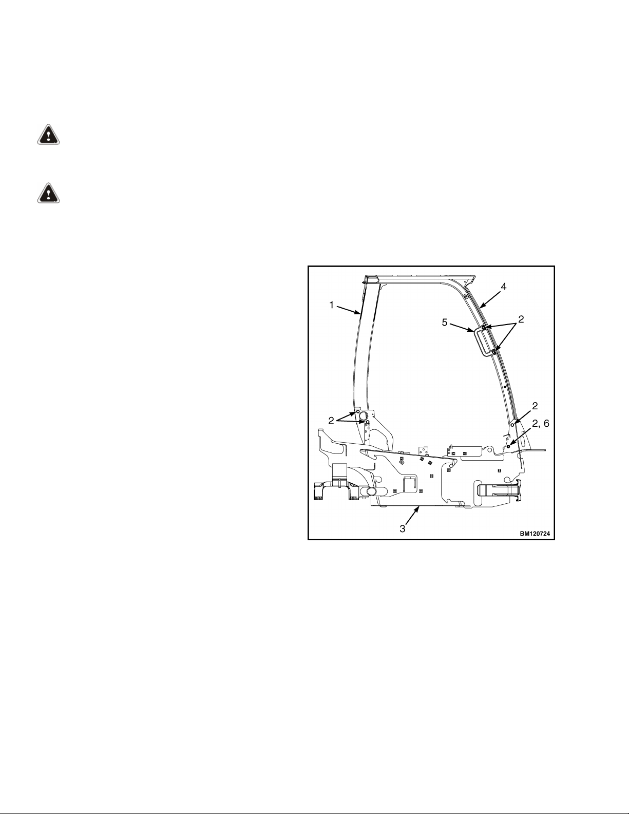
3. Remove capscrews from overhead guard rear
legs and frame. See Figure 18.
4. Remove dash and kick panel from cowl. See sec-
tion Hood, Seat, and Side Covers Replacement
for removal procedures.
5. Remove capscrews from overhead guard front
legs and frame. See Figure 18.
NOTE: When overhead guard is lifted from the
frame, make sure that any electrical wires are moved
through the holes in the frame so that they are not
damaged.
6. Using lifting device, remove overhead guard from
frame. See Figure 18.
7. Remove capscrews and handle from overhead
guard. See Figure 18.
1. OVERHEAD GUARD REAR LEG
2. CAPSCREW
3. FRAME
4. OVERHEAD GUARD FRONT LEG
5. HANDLE
6. NUT
Figure 18. Overhead Guard
Overhead Guard Replacement 0100 YRM 1766
18

INSTALL
NOTE: Make sure electrical wires are routed as no-
ted during removal to ensure that wires do not get
pinched.
1. Using lifting device, install overhead guard onto
frame.
2. Install capscrews onto overhead guard front legs
and frame. See Figure 18. Tighten capscrews to
66 N•m (49 lbf ft).
3. Install kick panel and dash onto cowl. See section
Hood, Seat, and Side Covers Replacement for in-
stall procedures.
4. Install capscrews onto overhead guard rear legs
and frame. See Figure 18. Tighten capscrews to
66 N•m (49 lbf ft).
5. Connect electrical wires as tagged during re-
moval.
6. Install handle and capscrews onto overhead
guard. See Figure 18.
Rain Top (Optional)
Remove
1. Remove two capscrews, two locknuts, two bush-
ings and two washers from bracket and rain top at
front center of overhead guard. See Figure 19.
2. Remove two capscrews, two locknuts, two bush-
ings and two washers from bracket and rain top at
front corners of overhead guard. See Figure 19.
3. Remove two capscrews, two wheel nuts and two
brackets from front center of overhead guard. See
Figure 19.
4. Remove two capscrews, two wheel nuts, right
bracket and left bracket from front corner of over-
head guard. See Figure 19.
NOTE: Note position of rain top on overhead guard
before removal.
5. Remove rain top from overhead guard. See Fig-
ure 19.
Clean and Inspect
1. Clean all remaining sealer residue from rain top
and overhead guard surfaces.
2. Inspect rain top and brackets for cracks. Replace
if necessary.
Install
1. Apply a continuous bead of sealer to back corners
of overhead guard. See (item 10) Figure 19.
NOTE: Apply even pressure to rain top to squeeze
down sealer to a thickness of 3 to 5 mm (0.118 to
0.197 in.).
2. Install rain top onto overhead guard as noted dur-
ing removal.
3. Install right bracket, left bracket two capscrews,
two wheel nuts, onto front corner of overhead
guard. See Figure 19.
4. Install two brackets, two capscrews, and two
wheel nuts to front center of overhead guard. See
Figure 19.
5. Install two capscrews, two bushings, two washers
and two locknuts onto bracket and rain top at front
corners of overhead guard. See Figure 19.
6. Install two capscrews, two bushings, two washers
and two locknuts onto bracket and rain top at front
center of overhead guard. See Figure 19.
0100 YRM 1766 Overhead Guard Replacement
19
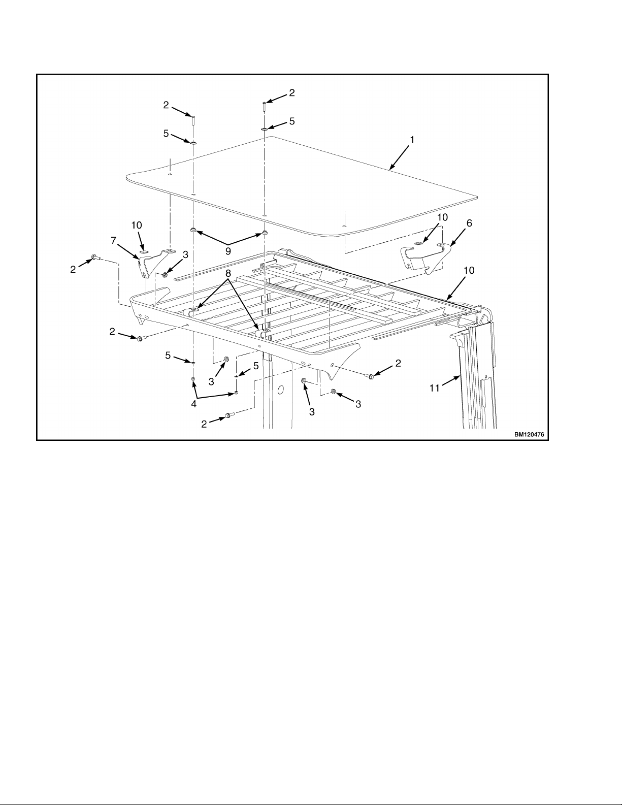
1. RAIN TOP
2. CAPSCREW
3. WHEEL NUT
4. LOCKNUT
5. WASHER
6. LEFT BRACKET
7. RIGHT BRACKET
8. CENTER BRACKET
9. BUSHING
10. SEALER
11. OVERHEAD GUARD
Figure 19. Overhead Guard Rain Top
Overhead Guard Replacement 0100 YRM 1766
20
 Loading...