

Page 1
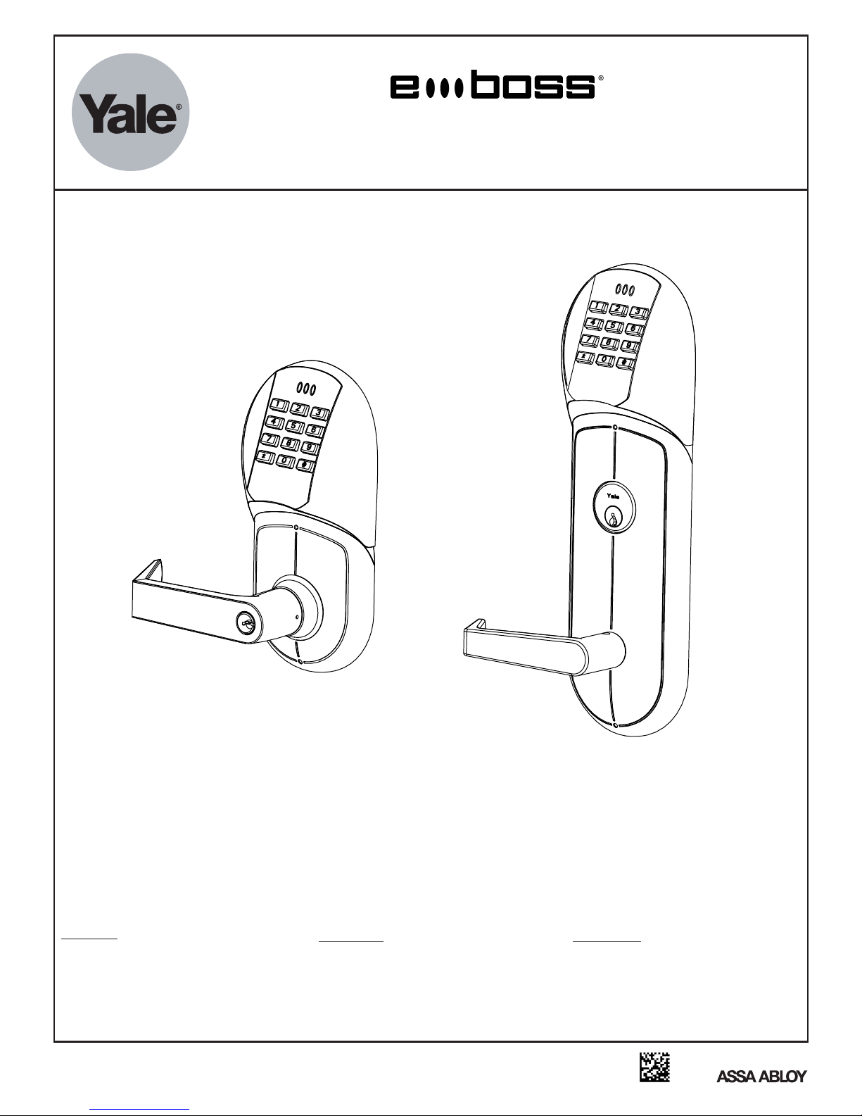
Programming/Troubleshooting
Instructions
E5400LN Cylindrical Series &
E890 Exit Device Trim Series
Operational Modes
Secure
Normal locked state. Any
assigned user code can gain
access. Lock/relocks
automatically.
An ASSA ABLOY Group brand
Lockout
Lockset will not accept any
assigned user codes except
for the Supervisor and
Emergency Codes.
E8850FL Mortise
Series
Passage
Maintains unlocked state.
Relocks by entering passage
code the second time
80-9150-8005-010 (10-12)
Page 2
Operational Check (Lock must be properly installed, refer to Installation Instructions)
Insert key into outside cylinder and rotate key
The key will retract the latchbolt
Inside lever retracts latchbolt
Enter factory set Emergency code 4321 [ * ] to unlock the outside lever and retract the
latchbolt (If emergency code does not work refer to Programming Instructions and reprogram
lock with a new master code and emergency code). The unit will relock after 10 seconds
If lock is functioning properly go to Programming Instructions.
If the lock does not function properly refer to troubleshooting page 7.
Lock Operation:
Programming is performed through a 12 digit keypad that has the numbers 0-9, [
The [ # ] acts as the entrance into programming mode (press & hold for 3 seconds). The [ # ] key also
acts as a enter key during programming and is used after each code entry. If the [ ] key is
reentered within 5 seconds after programming a code, the unit re-enters the programming mode
and looks for the next program code. The [ * ] Key acts a finish key after every user code entry
In normal operating mode.
Note:
1) No programming can be made until the master & emergency codes are changed from the
factory presets. Once the factory preset master or emergency codes are changed they can
not be reprogrammed back into the unit.
* ] and [ # ] keys.
#
2) When changing the master code, if the new master code verification does not match, then the
lock exits programming mode and the previous master code stays valid.
3) During programming mode, the yellow LED will flash continuously at normal rate. To enter
the lock into programming mode, the [ # ] key is held depressed for 3 seconds. The yellow
LED will begin flashing and the [ # ] key can be released. During each entry of the program
codes, the yellow LED will continue flashing. At the end of the last program value, the green
LED will short flash twice and the horn will emit 2 short tones to indicate that valid values
were entered. Pressing the [
sequence and a long red flash and 1 very long tone will result.
If a program value is entered out of range, the long red LED will light and a very long tone will
sound indicating an invalid entry. Programming mode can be reinitiated within 5 seconds of
the error by depressing the [ # ] key otherwise programming mode is exited.
4) After programming mode is exited, the lock always defaults to the standard user mode.
(Passage & Lockout are automatically exited)
5) Upon depression of each key, the yellow LED, if enabled (PCC=32), will light for 50 msec.
The sounder, if enabled (PCC=31) will sound one short tone.
6) Upon 3 (default) successive invalid faceplate entries (PCC=33), the lock will light one long
red flash along with a long tone and the faceplate will inhibit further entries for a
Preprogrammed (10 sec default) time (PCC=34).
During this inhibit time the sounder will
one short tone per second.
* ] key at any time during programming will exit the program
produce
Abbreviations Table
MC
PCC
VAL
#
*
def
dis
EN
LOC
Master Code
Program Command Code
Value
Enter Key
Finish Key
Default
Disable
Enable
User Location 1 through 99
2
An ASSA ABLOY Group brand
80-9150-8005-010 (10-12)
Page 3
Code Descriptions
User 1: Master Code –
Factory default setting of 1234
Codes should be 4 to 7 digits and entered followed by [ * ]
Assigns Supervisor and Emergency Codes
Used for Programming the lock
Will not allow the controller to unlock the mechanism
User 2: Emergency Code –
Factory default setting of 4321
Codes should be 4 to 7 digits and entered followed by [
Allows the controller to unlock the mechanism
Opens the lock for the Extended User time (10 second default)
Allows for entry when the controller low battery voltage is in the “blackout” condition
Allows access when the dead bolt (mortise lock) is thrown in all conditions
Will not allow for programming the lock
User 3: Supervisor Code
Codes should be 4 to 7 digits and entered followed by [
Allows all programming of the controller except for changing the Master Code
Does not have a default code, must be programmed
Allows access to unlock the door
Allows access when low battery exists
Has the ability to “delete all users” (Code 60) and to “delete a block of users” (Code 62)
however only Standard Users positions 6-99 can/will be deleted. The master, passage
and lock-out will not be affected.
Can utilize Code 61 “delete single user” to delete the emergency, passage & lock-out
codes. Note: if Code 61 is utilized for this purpose, the functions will be completely nonoperational (no code assigned) at this point (closet door)
* must be changed before programming can begin
* must be changed before programming can begin
* ]
* ]
User 4: Lockout Code
Codes should be 4 to 7 digits and entered followed by [
Used to restrict user codes 6-99 the ability to gain access
Only the Supervisor and Emergency Codes can override the lockout
Entering the lockout code the second time will allow Users 6-99 to re-gain entry.
Successful entry of lockout mode is indicated by a long green LED with 2 short beeps
with a pause followed by another 2 short beeps
Successful exit of lockout mode is indicated by a long green LED with 2 short beeps
User 5: Passage Code
Codes should be 4 to 7 digits and entered followed by [
Used to enable or disable the passage feature
After first entry, the lock remains unlocked
After second entry, the lock remains secure second
Operates when battery is low
Can be overridden by Lockout Code
Successful entry indicated by 1 long green LED along with 3 short beeps
Successful exit indicated by 1 long green LED with 2 short beeps
Users 6-99: Normal User Code
Codes should be 2 to 7 digits and entered followed by [
Used to unlock the lock for entry
Can not be created until the default master code has been changed and the emergency
code has been programmed
Codes 1234 & 4321 can not be used
The green LED will flash once per second upon entry of a correct code
A short red flash with 3 short beeps will occur if an incorrect code is entered
* ]
* ]
* ]
3
An ASSA ABLOY Group brand
80-9150-8005-010 (10-12)
Page 4

Programming Instructions:
®
Code used for entry. The Master Code is always User Number 1 and is used only for
programming. The Master Code will not unlock the lock.
Use the record log on the last page to assign and log all user codes before proceeding on
to programming. Store the log in a secure location.
Example:
User Type User Number User Code
Master 1 1 2 3 4 Factory Setting
Emergency 2 4 3 2 1 Factory Setting
Supervis o r 3 Select 4- 7 digits
L o c k o u t 4 Select 4-7 digits
Passage 5 Select 4-7 digits
U s e r 6 - 9 9 Select 2-7 digits per user
NO PROGRAMMING CAN BE MADE UNTIL THE MASTER & EMERGENCY CODES ARE
CHANGED FROM THE FACTORY SETTINGS
(Enter only underlined items into the keypad)
1-Change the Master Code
EXAMPLE: Change the Master Code from 1234 (factory default) to 3131.
#
(Hold pound depressed until Yellow LED blinks continuously)
Enter current Master Code 1234 #
Enter Program Command Code(PCC) 51# Yellow LED Blinks
Enter User Number 1 #
Enter New Master Code (4-7 digits) 3131#
Re-enter New Master Code (4-7 digits) 3131#
Note: If Master Code is unknown (Red LED will flash instead of Yellow) refer to step 3.
2-Change the Emergency Code
EXAMPLE: Change the Emergency Code from 4321 (Factory Defualt) to 4848
(Hold pound depressed until Yellow LED blinks continuously)
#
Enter current Master Code 3131#
Enter Program Command Code 51# Yellow LED Blinks
Enter User Number 2 # Yellow LED Blinks
(See Example 1)
Yellow LED Blinks
Yellow LED Blinks
Yellow LED Blinks
Yellow LED Blinks
Green LED Blinks
Yellow LED Blinks
Enter New Emergency Code (4-7digit) 4848# Yellow LED Blinks
Re-enter New Emergency Code (4-7digit) 4848 #
Emergency Code defaults to a 10 second Unlock time
Note: Emergency code is deleted when clear memory is used and must be reprogrammed.
An ASSA ABLOY Group brand
Yellow LED Blinks
Green LED Blinks
4
80-9150-8005-010 (10-12)
Page 5

3-Change the Master Code when Master Code has been forgotten or lost
Remove inside escutcheon
(Hold pound depressed until Yellow LED blinks continuously)
#
Depress the Program (PRGM) button located at the top of the
contr oller on the i n s ide
Yellow LED Blinks
Enter Program Command Code 51#
Enter User number 1 #
Yellow LED Blinks
Yellow LED Blinks
Enter New Master Code (4-7 digits) # Yellow LED Blinks
Re-enter New Master Code (4-7 digits) #
After the Master and Emergency Codes have been entered go to the User Programming
Command chart to add additional users: Supervisor, Passage, Lockout and Normal Users.
Yellow LED Blinks
Green LED Blinks
PROGRAM GUIDE
User Programming Commands
General
Format
MC# PCC User LOC VAL 1 VAL 2
To Enter a Master Code
# MC# 51# 1# (4-7 Digits)# (4-7 Digits)#
(Hold)
To Enter a Emergency Code
To Enter a Supervisor Code
To Enter a Lockout Code
To Enter a Passage Code
To Enter a Normal
User Code
(Hold)
# MC# 51# 2# (4-7 Digits)# (4-7 Digits)#
(Hold)
# MC# 51# 3# (4-7 Digits)# (4-7 Digits)#
(Hold)
# MC# 51# 4# (4-7 Digits)# (4-7 Digits)#
(Hold)
# MC# 51# 5# (4-7 Digits)# (4-7 Digits)#
(Hold)
# MC# 51# (6-99)# (2-7 Digits)# (2-7 Digits)#
User Programming Commands
Delete All Users (Deletes all codes back to defaults)
(Hold)
# MC# 60# 60#
Delete Individual User Codes
Delete Block Of Users
User Setting Reset
(Resets all Programming
Commands to default)
# MC# 72# 72#
(Hold)
# MC# 61# (6-99)#
(Hold)
# MC# 62# 1st LOC # 2nd LOC #
(Hold)
These Program
Modes and User
Codes can be
programmed
with the
Supervisor Code
(SC) or the Master
Code (MC)
5
An ASSA ABLOY Group brand
80-9150-8005-010 (10-12)
Page 6

Keypad Programming Commands
General Format MC# PCC VALUE
Audible Keypad Feedback 0=DISABLE, 1=ENABLE (Default =1)
(Hold)
# MC# 31# VAL #
Visual Keypad Feedback 0=DISABLE, 1=ENABLE (Default =1)
(Hold)
# MC# 32# VAL #
Keypad Attempts (1 thru 255) Default = 3 Attempts
(Hold)
# MC# 33# VAL #
Keypad Timeout (1 thru 255 Sec) Default = 10 Sec
(Hold)
# MC# 34# VAL #
Unlock Time (1 to 255 Sec) Default = 4 Sec
(Hold)
# MC# 44# VAL #
Set REX Unlock (1 to 255 Sec) Default = 10 Sec
(Hold)
# MC# 45# VAL #
Set Emergency Unlock Time (1 to 255 Sec) Default = 10 Sec
(Hold)
# MC# 46# VAL #
Features and Options:
1) Error Lockout: The lock will stop accepting key presses after 25 presses or three
successive [
short beep three times with one short red flash (indicating invalid code entry) and
continue to short beep once per second for the duration of the lockout time (no LED will
light). The lock will not accept any key presses during that 10 second (default) time. The
error lockout option overrides the horn disable function (PCC#31).
2) Low Battery Indicator: When the battery voltage drops below (5.8 volts) the lock will
short beep 4 times and allow entry. If the battery voltage drops below 5.4 volts (Blackout
Mode), 4 short beeps followed by 4 long tones
lock will function for the Supervisor and Emergency Codes only. See page 7 for the
battery replacement.
3) Request To Enter Input : A normally open contact that when closed will unlock the lock
for 5 seconds. Upon activation, the lock will emit one short green flash per second. This
feature requires hardwiring to the lock. This option will be sold as a kit which includes a
wiring harness that connects to the board. When the lock is in passage mode, activating
the request to enter will disable passage mode and relock the lock.
* ] entries without a valid code. Upon the third incorrect entry, the lock will
will sound, but the lock will not open. The
These Program Modes
and User Codes can be
programmed with the
Supervisor Code (SC) or
the Master Code (MC)
4) Peizo Sounder: 85dBA minimum. Short tone with each keystroke. Can be disabled by
Supervisor code.
5) LED Indicator: All three LED’s can be disabled by the Supervisor Code; however they
are still active in the programming mode. Yellow-programming mode, Green- successful
entry, Red-Indicates input error.
6) Re-lock Duration: The duration that the lock remains unlocked can be adjusted from 1 to
255 seconds. Default at 4 seconds.
7) Hardwire: The board comes standard with a 2 pin input connector to allow hardwiring
an external 9 VDC power supply (Part # 784). This option is sold as a kit including a
An ASSA ABLOY Group brand
wiring harness that connects to connectors provided on the board.
6
80-9150-8005-010 (10-12)
Page 7

Troubleshooting
P r o b l em
Green light comes on but lever will not retract latchbolt.
Solution
Check lockbody connection. Check cylinder tail
Check door Prep (refer to door templates).
piece length (see Installation Instructions).
Problem
No Lights come on when pushbuttons are depressed.
Solution
Ensure Visual Keypad Feedback is set to Enable (See page 6). Check battery installation.
Check keypad connection.
Problem
No Audible when pushbuttons are depressed.
Solution
Ensure Audible Keypad Feedback is set to Enable (See page 6). Check battery installation.
Check keypad connection.
Problem
Factory default codes not working
Solution
Reprogram default codes (Delete All Users) (See page 5) .
Problem
User codes not working
Solution
Ensure Lockout code has not been entered (See page 3). Check battery power (lock maybe in
Blackout Mode). See below for battery replacement. Check lockbody connection.
Problem
Lock stays unlocked
Solution
Ensure Passage code has not been entered (See page 3). Check cylinder tail piece length
(see Installation Instructions). Check lockbody connection.
Battery Replacement
The lock goes into Blackout Mode when the voltage drops to 5.4V. If this happens users 6-99
will be locked out. Supervisor and Emergency codes are the only codes that will allow access.
The codes will not be lost during battery replacement or low power conditions. Codes are stored
in non-volatile memory. To replace the batteries remove the screw on the Battery Escutcheon
and remove the escutcheon. Replace all 6 “AA” (alkaline only) batteries in the correct polarity
position. Reinstall the escutcheon. Enter a known user code to ensure lock functions correctly.
An ASSA ABLOY Group brand
7
80-9150-8005-010 (10-12)
Page 8

eBOSS® User Log
Door Description
Installation Date
User User Name PIN Number Notes
1 Master Code
2 Emergency Code
3 Su pervisor
4 Lockout
5 Passage
6
7
8
9
10
11
12
13
14
15
16
17
18
19
20
21
22
23
24
25
26
27
28
29
30
31
32
33
34
35
An ASSA ABLOY Group brand
80-9150-8005-010 (10-12)
8
Page 9

36
37
38
39
40
41
42
43
44
45
46
47
48
49
50
51
52
53
54
55
56
57
58
59
60
61
62
63
64
65
66
67
68
69
70
71
72
73
74
75
76
77
An ASSA ABLOY Group brand
9
80-9150-8005-010 (10-12)
Page 10

78
79
80
81
82
83
84
85
86
87
88
89
90
91
92
93
94
95
96
97
98
99
Product Support Tel 800. • www.yalelocks.com810.WIRE (9473)
Yale Locks & Hardware is a division of Yale Security Inc., an ASSA ABLOY Group company.
Yale® and eBoss® are registered trademarks of Yale Security Inc., an ASSA ABLOY Group company. Other products' brand names may be trademarks or registered trademarks of their
respective owners and are mentioned for reference purposes only. These materials are protected under U.S. copyright laws. All contents current at time of publication.
An ASSA ABLOY Group brand
Yale Security Inc. reserves the right to change availability of any item in this catalog, its design, construction, and/or its materials.
All rights reserved. Reproduction in whole or in part without the express written permission of Yale Security Inc. is prohibited.
Copyright © 2008, 2012 Yale Security Inc., an ASSA ABLOY Group company.
10
80-9150-8005-010 (10-12)
 Loading...