

Page 1
STATION MONITOR
SM-5000
O
PERATING
Thank you for your purchase. The SM-5000 Station Monitor provides a visual display of the VFO-A band spectrum. Both strong
and weak signals are clearly depicted. The integrated stereo speakers provide comfortable receiver audio.
SAFETY INFORMATION
Do not modify this equipment.
Do not place this equipment in a location exposed to dust and/or high humidity.
Do not expose the SM-5000 Station Monitor to direct sunlight or excessive temperatures.
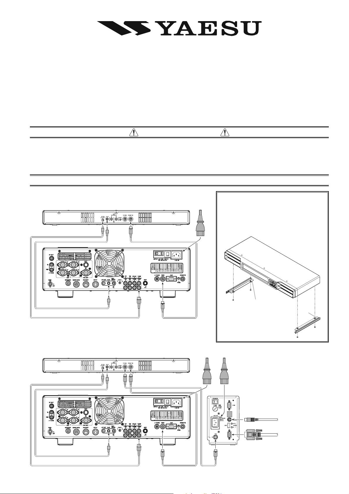
INSTALLATION
Before installing the SM-5000, turn off the Main Power Switch on the
rear panel of the FTDX5000.
F
SM-5000
V
8
A
.
-
3
V
1
+
X
R
T
M
O
R
F
M
ANUAL
SIDE PLATE INSTALLATION
If the SM-5000 will be placed on top of
the FTDX5000, attach the supplied Side
Plates on both sides of the SM-5000 with
N
I
C
the supplied screws.
A
~
FTDX5000
V-AF Cable supplie d with SM-5000
()
DC POWER Cable supplied with SM-5000
SM-5000
FTDX5000
V-AF Cable supplie d with SM-5000
()
DC POWER Cable supplied with SM-5000
F
A
V
()
F
V
8
.
3
1
+
()
U
A
M
D
V
O
T
F
A
V
V
8
.
3
1
+
U
M
D
Mini-DIN Cable supp lied with SM-5000
()
“L” mark (Bottom side
“R” mark (Bottom side
Note the left and right orienta-
)
)
tion of the Side Plates and install them correctly.
X
R
T
M
O
R
F
N
N
I
I
C
C
A
A
~
~
DMU-2000
KEYBOARD
V
8
.
3
1
+
U
M
D
Mini-DIN Cable supp lied with SM-5000
()
X
R
T
Mini-DIN Cable s upplied with DMU-2000
()
MONITO R
-1-
Page 2
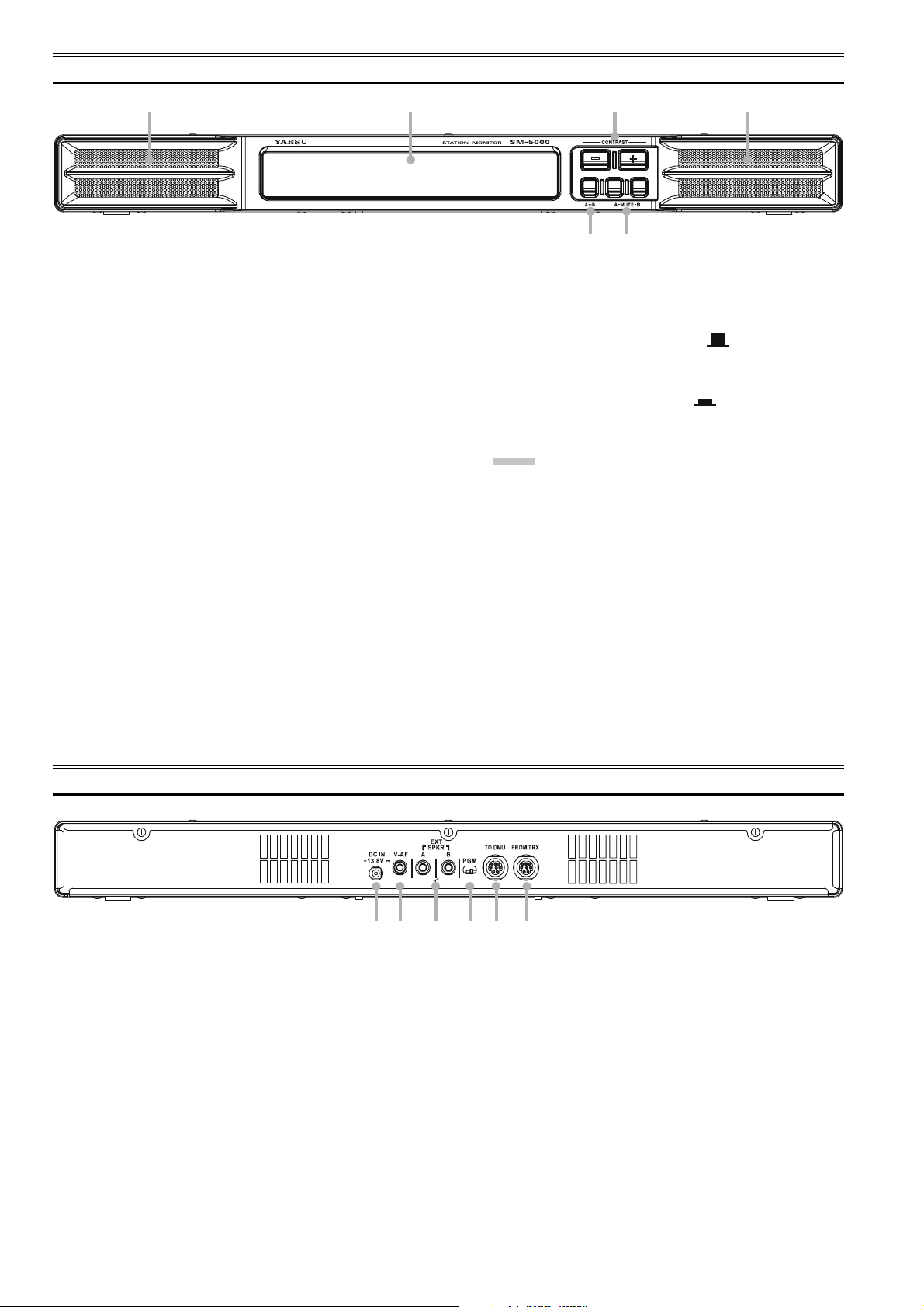
FRONT PANEL SWITCHES
Speaker
Dual 2.6” x 1” (65 x 25 mm) oval speakers direct the sound
toward the front. The audio response is specially tailored
for shortwave reception.
Independent Left or Right mute capability is provided for
VFO-A and VFO-B on the Station Monitor, without changing any settings on the transceiver.
Display
This LCD Monitor displays the Spectrum Scope of VFOA band activity.
[
CONTRAST
These switches are used for adjustment of the LCD Contrast Setting and the Audio Setting.
Press both switches simultaneously, to toggle the adjustment mode between “LCD Contrast Setting” and “Audio
Setting”.
Refer to page 6 for the details of the “Audio Setting”, and
refer to page 7 for the details of the “LCD Contrast Setting”.
](
[+]
/
[–]
)
Switch
[
A+B] Switch
Selects the speaker output mode during Dual Receive operation.
When this switch is un-pressed ( ), the left speaker
produces audio from the VFO-A receiver, while the right
speaker produces audio from VFO-B receiver.
When this switch is depressed ( ), mixed audio from
the VFO-A and VFO-B receivers is produced by both
speakers.
NOTE:
1) Requires FTDX5000 Menu item “108 ROUT
HEADPHN” be set to “SEPARATE”.
2) When receiving only VFO-A or VFO-B, the audio is
routed to both speakers, regardless of the switch position.
[
MUTE-A] / [MUTE-B] Switches
The [MUTE-A] switch allows you to mute the audio from
the VFO-A receiver. Similarly, the [MUTE-B] switch allows you to mute the audio from the VFO-B receiver.
This can be particularly useful during Dual Receive operation, when you want to concentrate on just one receiver
for a moment.
REAR PANEL CONNECTIONS
DC IN +13.8V Jack
Connect the supplied DC cable between this jack and
+13.8V jack on the FTDX5000 transceiver.
V-AF Jack
Connect the supplied connection cable between this jack
and V-A F jack on the FTDX5000 transceiver.
EXT SPKR Jacks
Connect the external speakers to these jacks, if desired.
Inserting a plug into the A jack disables the left side speaker
of the SM-5000. Similarly, inserting a plug into the B
jack disables the right side speaker of the SM-5000.
[
PGM] Switch
This slide switch is used for updating the SM-5000 firmware. The update software and instructions are available
for download from the Vertex Standard website (http://
www.yaesu.com/).
TO DMU Jack
To use the optional DMU-2000 Data Management Unit
at the same time, connect the cable supplied with the DMU-
2000 between this jack and the TRX jack on the DMU-
2000.
FROM TRX Jack
Connect the supplied control cable between this jack and
the DMU jack on the FTDX5000 transceiver.
- 2 -
Page 3
ABOUT THE SPECTRUM SCOPE
The SM-5000 Spectrum Scope provides a visual display of an amateur band segment tuned by the VFO-A receiver. The default
bandwidth allows you to see both strong and weak signals clearly depicted on the monitor screen. During transmission, the
transmitter’s waveform will be displayed, except when the frequency span is set to 2500 kHz in the CTR (Center) display
mode or set to 1000/2500 kHz in the FIX (Fixed) display mode.
The LBWS (Limited Band Width Sweep) function provides very high-speed signal detection over a limited segment of the
currently displayed spectrum. The CTR (Center) display mode will let you monitor signals close to your current frequency (your
frequency is located at the center of the screen). When the FIX (fixed) mode is engaged, the left band edge frequency is fixed, and
your operating frequency may be indicated within the displayed bandwidth. These features have been carefully considered for
their utility in actual Amateur Radio operation.
Note: The vertical axis of the Spectrum Scope display is approximately 10 dB per division.
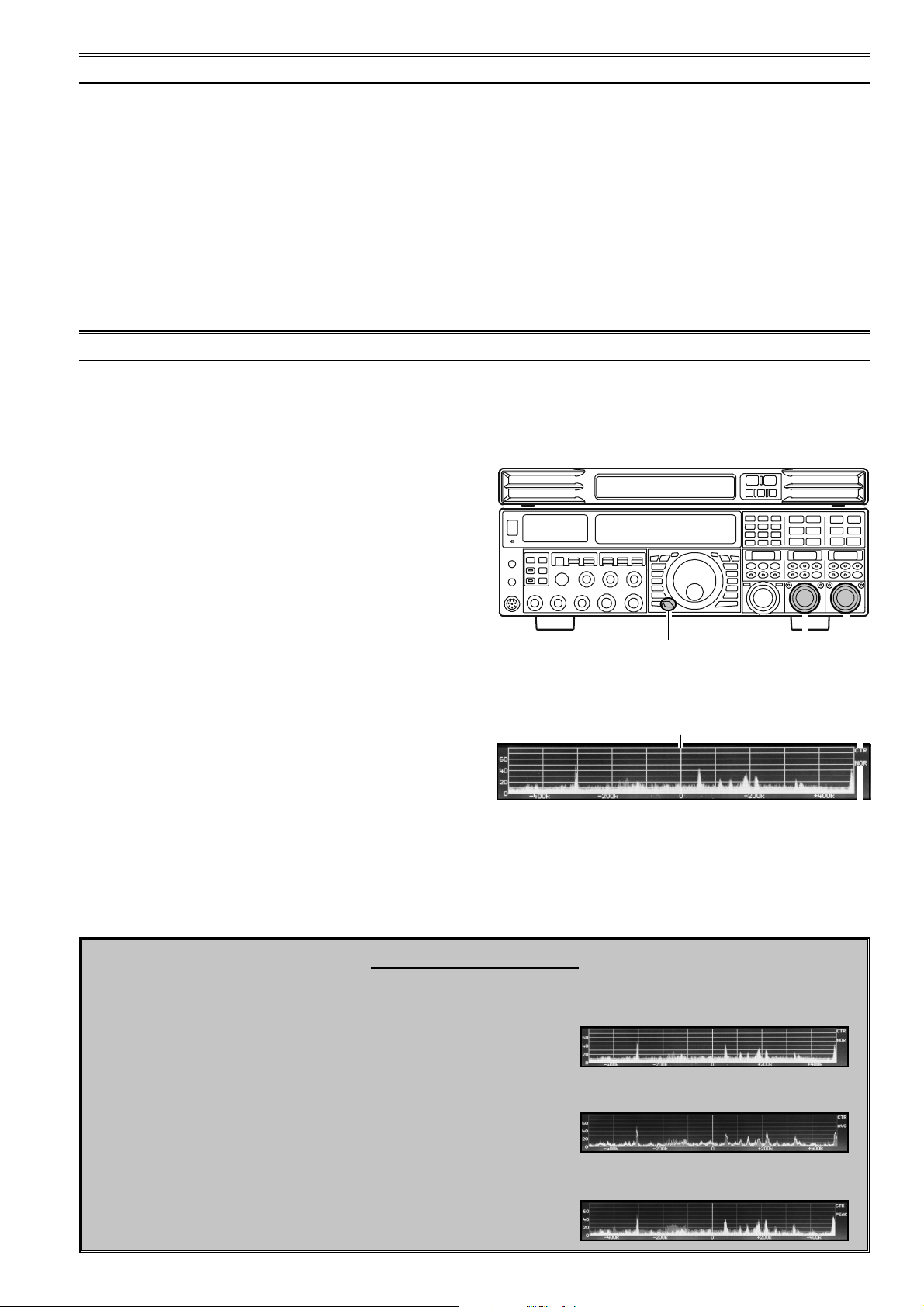
USING THE CTR (CENTER) DISPLAY MODE
In the CTR mode, the operating frequency is shown at the center of the monitor screen. The selected Spectrum Scope frequency
bandwidth is displayed across the monitor screen. Signals received on the VFO-A band are shown. (To show signals more clearly
and easily, the LBWS (Limited Band Width Sweep) function lets you perform a high-speed, high-resolution sweep of a limited
band segment (See page 4 for details).
1. Press and hold the FTDX5000 [C.S] key for 2 seconds to
to engage the Scope Menu mode.
The SUB DISPLAY-I window will show the Group name
(SCOPE), while the SUB DISPLAY-II window will show
the Menu item. The SUB DISPLAY-III window shows
the setting of the currently-selected Menu item.
2. Rotate the (VFO-A)[SELECT] knob to select the Menu
item “MODE”.
3. Rotate the (VFO-B)[SELECT] knob to select “CENTER”.
The current VFO-A frequency is displayed at the center
of the screen.
4. Rotate the (VFO-A)[SELECT] knob to select the Menu
item “SPAN”, then rotate the (VFO-B)[SELECT] knob
to select the desired frequency span to monitor.
Available selections are: 25 kHz, 50 kHz, 100 kHz, 250
kHz, 500 kHz, 1000 kHz,
and
2500 kHz.
5. Rotate the (VFO-A)[SELECT] knob to select the Menu item
“ATT”, then rotate the (VFO-B)[SELECT] knob to select
the display attenuation value according to current propagation conditions, your operating frequency, and antenna, etc.
Available selections are: 0 dB, 10 dB,
and
20 dB.
6. Press the [C.S] key briefly to save the new setting and
exit to normal operation.
[
C.S] Switch
Current VFO-A Frequency
(
VFO-A)[SELECT] Knob
(
VFO-B)[SELECT] Knob
OPERATING Mode
TRACE Mode
NOR: Normal
AVG: Average
PEAK: Peak Hold
CTR
CHANGING THE TRACE MODE
1. Press and hold the FTDX5000 [C.S] key for 2 sec-
onds to engage the Scope Menu mode.
The SUB DISPLAY-I window will show the Group
name (SCOPE), while the SUB DISPLAY-II window
will show the Menu item. The SUB DISPLAY-III win-
dow shows the setting of the currently-selected Menu
item.
2. Rotate the (VFO-A)[SELECT] knob to select the
Menu item “TRACE”, then rotate the (VFO-
B)[SELECT] knob to select the desired trace mode.
Available selections are shown at the right.
3. Press the [C.S] key briefly to save the new setting and
exit to normal operation.
NORMAL: The real-time signal strength will be displayed.
Normally, you will want to use this mode.
AVERAGE: The averaged signal strength will be dis-
played.
PEAKHOLD: The Peak signal level will be displayed and
held until the frequency is changed.
-3-
Page 4

USING THE LBWS (LIMITED BAND WIDTH SWEEP) FUNCTION
LBWS (Limited Band Width Sweep) is a function that sweeps a limited segment of the Spectrum Scope span without changing
the span (bandwidth). As the sweep segment becomes narrower, the speed becomes faster, and the accuracy and resolution are
enhanced.
The bandwidth can be set to 50 %, 30 %, or 10 % of the full span. The sweep speed will increase as follows: 50 %: about 2 times
faster, 30 %: about 3 times faster, 10 %: about 10 times faster.
1. Press and hold the FTDX5000 [C.S] key for 2 seconds to
engage the Scope Menu mode.
The SUB DISPLAY-I window will show the Group name
(SCOPE), while the SUB DISPLAY-II window will show
the Menu item. The SUB DISPLAY-III window shows
the setting of the currently-selected Menu item.
2. Rotate the (VFO-A)[SELECT] knob to select the Menu
item “MODE”, then rotate the (VFO-B)[SELECT] knob
to select the desired sweep bandwidth.
LBWS-1: The sweep speed becomes about 2 times faster
(The bandwidth decreases to 50 %).
LBWS-2: The sweep speed becomes about 3 times faster
(The bandwidth decreases to 30 %).
LBWS-3: The sweep speed becomes about 10 times faster
(The bandwidth decreases to 10 %).
Note: The “CENTER” and “FIX” selections are not select
items of the LBWS function. Do not select these selections.
4. Rotate the (VFO-A)[SELECT] knob to select the Menu
item “SPAN”, then rotate the (VFO-B)[SELECT] knob
to select the desired frequency span to monitor.
Available selections are: 25 kHz, 50 kHz, 100 kHz, 250
kHz, 500 kHz, 1000 kHz,
and
2500 kHz.
5. Rotate the (VFO-A)[SELECT] knob to select the Menu item
“ATT”, then rotate the (VFO-B)[SELECT] knob to select
the display attenuation value according to current propagation conditions, your operating frequency, and antenna, etc.
Available selections are: 0 dB, 10 dB,
and
20 dB.
6. Press the [C.S] key briefly to save the new setting and
exit to normal operation.
[
C.S] Switch
Current VFO-A Frequency
Current Sweep Bandwidth
(
VFO-A)[SELECT] Knob
(
VFO-B)[SELECT] Knob
OPERATING Mode
LBWS
NOTE:
The Trace Mode cannot be selected with the LBWS function.
SELECTING THE SWEEP AREA
1. Press and hold the FTDX5000 [C.S] key for 2 sec-
onds to to engage the Scope Menu mode.
The SUB DISPLAY-I window will show the Group
name (SCOPE), while the SUB DISPLAY-II window
will show the Menu item. The SUB DISPLAY-III win-
dow shows the setting of the currently-selected Menu
item.
2. Rotate the (VFO-A)[SELECT] knob to select the
Menu item “LBWS”, then rotate the (VFO-
B)[SELECT] knob to select the desired sweep area.
Available selections are shown at the right.
3. Press the [C.S] key briefly to save the new setting and
exit to normal operation.
LBWSx L: The Spectrum scan sweeps the band segment
on the lower side of the operating frequency.
LBWSx M: The Spectrum scan sweeps the band segment
centered on the operating frequency.
LBWSx H: The Spectrum scan sweeps the band segment
on the upper side of the operating frequency.
x: 1, 2, or 3; indicates the sweep segment that is desig-
nated in the Menu item “MODE”, described previously.
The above examples are “2” (LBWS-2).
- 4 -
Page 5

USING THE FIX (FIXED) MODE
The FIX mode is convenient when you want to monitor an entire amateur band.
The starting point, located at the left edge of the screen, can be set for each amateur band via FTDX5000 Menu items (“131 SCP
1.8 FIX” ~ 141 SCP 50.0 FIX”). Even if the screen span (bandwidth) is changed, the start frequency will not be changed. By
watching the screen, you can move your operation to a clear channel or find frequencies where interesting activity appears on the
display.
1. Press and hold the FTDX5000 [C.S] key for 2 seconds to
engage the Scope Menu mode.
The SUB DISPLAY-I window will show the Group name
(SCOPE), while the SUB DISPLAY-II window will show
the Menu item. The SUB DISPLAY-III window shows
the setting of the currently-selected Menu item.
2. Rotate the (VFO-A)[SELECT] knob to select the Menu
item “MODE”.
3. Rotate the (VFO-B)[SELECT] knob to select “FIX”.
The current VFO-A frequency is indicated on the screen
by a bold vertical line, for ease of status recognition.
4. Rotate the (VFO-A)[SELECT] knob to select the Menu
item “SPAN”, then rotate the (VFO-B)[SELECT] knob
to select the desired frequency span to monitor.
Available selections are: 25 kHz, 50 kHz, 100 kHz, 250
kHz, 500 kHz, 1000 kHz,
and
2500 kHz.
5. Rotate the (VFO-A)[SELECT] knob to select the Menu item
“ATT”, then rotate the (VFO-B)[SELECT] knob to select
the display attenuation value according to current propagation conditions, your operating frequency, and antenna, etc.
Available selections are: 0 dB, 10 dB,
and
20 dB.
6. Press the [C.S] key briefly to save the new setting and
exit to normal operation.
[
C.S] Switch
Current VFO-A Frequency
(
VFO-A)[SELECT] Knob
(
VFO-B)[SELECT] Knob
OPERATING Mode
TRACE Mode
NOR: Normal
AVG: Average
PEAK: Peak Hold
FIX
ADVIC E:
If the VFO-A frequency is outside of the spectrum shown on
the screen, the operating frequency will be "shown" in the
lower area of the display as “
” or “
<<<
”.
>>>
NOTE:
When using the FIX (Fixed) Mode, the PEAK (Peak Hold)
Display does not refresh when changing the frequency. Return to CTR (Center) Display Mode to refresh the display.
-5-
Page 6

AUDIO SETTING
AUDIO MUTING
The Audio Mute feature be particularly useful during Dual Receive operation, when you want to concentrate on just one receiver
for a moment.
[
Press the [MUTE-A] switch to toggle the VFO-A receiver
audio “on” and “off”.
Press the [MUTE-B] switch to toggle the VFO-B receive
audio “on” and “off”.
AUDIO MIXING
The Audio Mixing feature combines the left and right speakers to project excellent fidelity audio across a broad listening area.
MUTE-A] Switch
[
MUTE-B] Switch
When the [A+B] switch is depressed ( ), mixed audio
from VFO-A and VFO-B receivers is produced from both
speakers, creating excellent fidelity audio in a wide range.
When the [A+B] switch is un-pressed ( ), the left
speaker produces audio from VFO-A receiver, while the
right speaker produces audio from VFO-B receiver.
SOUND QUALITY
You may control the received audio with four additional choices:
1. If needed, press both [CONTRAST(+)] and [CON-
TRAST
“Audio Setting”.
The Audio Setting window will appear on the display.
Note: Pressing of the [CONTRAST(+)]/[CONTRAST
switch will store the last selected “Contrast Setting Mode”
or “Audio Setting Mode” to memory.
2. Press the [CONTRAST
the desired audio response. Available selections are:
CLEAR: High Fidelity receiver audio, full quality,
MILD: The high pitch tones of the receiver audio
SOFT: The low frequency base range of the receiver
LOUDNESS: The low frequency base range of the received
3. A few seconds after pressing the [CONTRAST
switch, the Audio Setting window will close.
(–)]
switches to change the adjustment mode to
(–)]
switch repeatedly to choose
clear, readable sound.
are reduced, without changing the low base
sound quality.
audio is boosted and the high pitch tones are
reduced.
audio is boosted while preserving clear
sound quality, with high readability.
(–)]
(–)]
[
A+B] Switch
[
CONTRAST
[
CONTRAST
(–)]
Switch
(+)]
Switch
- 6 -
Page 7

AUDIO SETTING
PHASE INVERSION
When the received audio phase is reversed, the SM-5000 gives depth to the audio sound.
1. If needed, press both [CONTRAST(+)] and [CON-
TRAST
(–)]
switches to change the adjustment mode to
“Audio Setting”.
The Audio Setting window will appear on the display.
Note: Pressing of the [CONTRAST(+)]/[CONTRAST
(–)]
switch will store the last selected “Contrast Setting Mode”
or “Audio Setting Mode” to memory.
2. Press the [CONTRAST(+)] switch to toggle the audio
phase “ON (reversed phase)” or “OFF (normal response)”.
3. A few seconds after pressing the [CONTRAST
(+)]
switch, the Audio Setting window will close.
DISPLAY SETTING
ADJUSTING THE CONTRAST
You may adjust the contrast for best viewing in sunlight, dusk, or night allowing for best readability.
1. If needed, press both [CONTRAST(+)] and [CON-
TRAST
“LCD Contrast Setting”.
The Contrast window will appear on the display.
Note: Pressing of the [CONTRAST(+)]/[CONTRAST
switch will store the last selected “Contrast Setting Mode”
or “Audio Setting Mode” to memory.
2. Press the [CONTRAST(+)] switch to increase the contrast of the display.
3. Press the [CONTRAST
of the display.
4. A few seconds after pressing the [CONTRAST(+)]/
[
CONTRAST
(–)]
switches to change the adjustment mode to
(–)]
switch to reduce the contrast
(–)]
switch, the Contrast window will close.
(–)]
ADVIC E:
When a contrast level is too high, it is difficult to watch the
“Average” and “Peak hold” indication (See page 3).
[
CONTRAST
[
CONTRAST
[
CONTRAST
[
CONTRAST
(–)]
(–)]
Switch
(+)]
Switch
Switch
(+)]
Switch
SPECTRUM SCOPE DISPLAY “ON/OFF”
You may turn off the Spectrum Scope Display.
1. Press and hold the FTDX5000 [C.S] key for 2 seconds to
engage the Scope Menu mode.
The SUB DISPLAY-I window will show the Group name
(SCOPE), while the SUB DISPLAY-II window will show
the Menu item. The SUB DISPLAY-III window shows
the current setting of the currently-selected Menu item.
2. Rotate the (VFO-A)[SELECT] knob to select the Menu
item “DISPLAY”, then rotate the (VFO-B)[SELECT
knob to select “OFF”.
The Spectrum Scope Display turns off.
3. Press the [C.S] key briefly to save the new setting and
exit to normal operation.
To turn the Spectrum Scope Display on, repeat the above procedure, rotating the (VFO-B)[SELECT] knob to select “ON”
as in step “2” above.
]
[
C.S] Switch
(
VFO-A)[SELECT] Knob
(
VFO-B)[SELECT] Knob
DISPLAY DIMMER
When the FTDX5000 [DIM] button is pressed, the illumination level of the SM-5000 will also be reduced.
The amount of brightness may be set via FTDX5000
Menu item “011 DISP DIM ELCD”.
-7-
Page 8

SUPPLIED OPTION
DC POWER Cable (USA/EXP version: T9101593) .......... 1
(European version: T9101596) ........... 1
Mini-DIN Cable (USA/EXP version: T9101526) .......... 1
(European version: T9101594) ........... 1
RESETTING THE MICROPROCESSOR
Press and hold the [CONTRAST(+)] and [CONTRAST
switches while turning the FTDX5000 transceiver on to reset
the Sound Quality, Phase Inversion, and Contrast settings to
their factory default.
V-AF Cable (T9101595) .................................................... 1
Side Plate-L (RA1227300 + RA1231900) ......................... 1
Side Plate-R (RA1227400 + RA1231900) ......................... 1
Screw (M3x4: U9900264) .................................................. 4
Operating Manual ............................................................... 1
SPECIFICATIONS
Input Voltage: 13.8 VDC, 1 A (max); Supplied from FTDX5000 Transceiver
Operating Temperature Range: +14 °F to +122 °F (–10 °C to +50 °C)
Speaker Aperture: 2.6” x 1” (65 x 25 mm); Left and right speakers are identical
Maximum Audio Output: 1.5 W + 1.5 W (@8 Ω)
Case Size (WxHxD): 18” x 1.8” x 7.1” (462 x 45 x 181 mm)
Weight (Approx.): 5.5 lbs (2.5 kg)
(–)]
VERTEX STANDARD CO., LTD.
4-8-8 Nakameguro, Meguro-Ku, Tokyo 153-8644, Japan
VERTEX STANDARD
US Headquarters
10900 Walker Street, Cypress, CA 90630, U.S.A.
YAESU UK LTD.
Unit 12, Sun Valley Business Park, Winnall Close
Winchester, Hampshire, SO23 0LB, U.K.
VERTEX STANDARD HK LTD.
Unit 1306-1308, 13F., Millennium City 2, 378 Kwun Tong Road,
Kwun Tong, Kowloon, Hong Kong
VERTEX STANDARD (AUSTRALIA) PTY., LTD.
Tally Ho Business Park, 10 Wesley Court, East Burwood, VIC, 3151
Copyright 2011
VERTEX STANDARD CO., LTD.
All rights reserved
No portion of this manual
may be reproduced without
the permission of
VERTEX STANDARD CO., LTD.
Printed in Japan.
EAG02X104
- 8 -
 Loading...