

Page 1
C4FM/FM 144/430MHz
DIGITAL/ANALOG TRANSCEIVER
FT-70D
FT- 70D
Operating Manual
R
E
Page 2

Contents
Introduction .............................................................. 1
Quick Guide ............................................................. 2
Controls & Connections ......................................... 3
Transceiver ............................................................... 3
The Keypad Functions .............................................. 5
Display ...................................................................... 6
Safety Precautions (Be Sure to Read
About this manual ................................................. 11
Supplied Accessories and Options ..................... 11
Supplied Accessories ............................................. 11
Available Options .................................................... 11
Preparation ............................................................. 12
Installing the Antenna ............................................. 12
Attaching the Belt Clip ............................................ 12
Installing the Battery Pack ...................................... 12
Removing the Battery Pack .................................... 12
Charging the Battery Pack .................................... 13
Charging the Battery Pack using the Battery Charger
Charging the Battery Pack using the Rapid Charger (SBH-28
External Power Supply .......................................... 13
Connecting an External Power Supply for Use in Vehicle
Connecting to an E xternal Power Supply Using a Power Cable
Operation ................................................................ 14
Turning the Transceiver ON .................................... 14
Adjusting the Volume Level .................................... 14
Adjusting the squelch setting ................................. 15
Selecting a Frequency Band .................................. 15
Tuning to a Frequency ............................................ 15
Changing the Frequency Step ............................ 15
Selecting the Communication Mode ...................... 16
Using AMS (Automatic Mode Select) function .... 16
Fixing the Communication Mode ......................... 17
Transmission ........................................................... 17
Changing the Transmission Power Level ............... 18
Locking Keys and DIA L knob ................................. 18
Programmable key function .................................... 18
Using the convenient Digital C4FM feature ........ 19
About the Digital Group ID (DG-ID) feature ........... 19
Communicating with the DG-ID feature ................. 19
Setting the transmit and receive DG-ID number to
“00” for communicating with all other stations
using C4FM digital mode
Communicating only with the specific members
by setting the DG-ID number except for “00”
About the GM(Group Monitor) feature ................... 21
Displaying the information of the other
station received by GM (Group Monitor) function
Repeater Operation ............................................... 23
Communicating Via the Repeater .......................... 23
Tone Calling (1750 Hz burst tone
Using the Memory ................................................. 24
Register ing to Memory Channels ........................... 25
Recalling a Memory Channel ................................. 25
Clearing Memories ................................................. 26
Recalling the Home Channels ................................ 26
Changing the Home Channel Frequency ............... 26
Split Memory ........................................................... 26
Using Memory Tag .................................................. 26
Using Memory Bank ............................................... 26
Scanning Function ................................................ 27
) ................... 8
.... 13
)
... 13
... 13
... 13
... 19
... 20
.... 22
) .......................... 23
VFO Scan ................................................................ 27
Memory Channel Scanning .................................... 27
Setting the Receive Operation When Scanning Stops
Weather Alert Scan ................................................ 28
Skip Memory Channel and Specified Memory Channel
Programmable Memory scan (PMS
Dual Receive (DW) feature ..................................... 29
Using the WIRES-X Function ................................ 30
WIRES-X feature .................................................... 30
Connecting to a WIRES-X node
in the C4FM mode (*Recommended) ... 30
Connect and communicate with WIRES-X in analog mode
Disconnecting from the node or room ................. 33
Convenient Functions ........................................... 34
Tone squelch feature .............................................. 34
Digital Code squelch (DCS) feature ....................... 34
New PAGER (EPCS) feature .................................. 34
Digital Personal ID (DP-ID) feature ........................ 34
Using Set Mode ...................................................... 35
Display and Key Lamp Dimmer .............................. 35
Changing the Beep Volume .................................... 35
Automatic Power OFF (APO
Time Out Timer (TOT
Busy Channel Lock- Out (BCLO
Receiver Batter y Save Function ............................. 35
Password Feature ................................................... 35
Tables of Set Mode Operations .............................. 36
Restoring to Defaults (Reset
All Reset .............................................................. 38
Set Mode Reset .................................................. 38
Specifications ........................................................ 39
) ............................................ 35
) ...................... 29
) ................................. 35
) ............................ 35
) ............................... 38
... 28
... 29
... 33
Page 3

Introduction
Thank you for purchasing this Yaesu product.
PThe FT-70DR/FT-70DE is a handheld transceiver for operation in the 144 MHz
and 430 MHz Amateur radio bands. It is compatible with the Analog FM and C4FM
modes.
PThe FT-70DR/FT-70DE is rugged and compact (W60 × H98 × D33 mm (2.36″ × 3.86″
× 1.30″)) providing splash, water, and dust resistant features conforming to IP54 for
mobile and field operation.
PThe AMS (Automatic Mode Select) feature automatically selects the analog FM and
C4FM digital modes, according to the signal of the other station.
19
(
PWith the GD-ID (Digital Group ID) feature
enables automatically locating, and communicating with other stations that have the
same DG-ID number within contact range, by utilizing a matching group ID number
from 00 to 99.
PThe Digital Personal ID (DP-ID) feature may communicate only by the transceivers
registered the individual ID information that is different for each transceiver included
in the transmission radio wave of C4FM digital communication.
Compatible with analog FM mode and C4FM digital modes................................................
r
Equipped with AMS (Automatic Mode Select) Feature ....................................................... 16
r
The DG-ID function automatically checks to find if there are any stations with
r
the GM function in operation on the same frequency within communication range
The DP-ID feature may recall/standby only the other stations that are set with
r
the C4FM Digital transceiver specific number.
High-brightness LED for easy viewing of the MODE/STATUS indicator ...............................
r
Supports Yaesu WIRES-X Internet linking, enabling communication with
r
remote partners via the Internet ..........................................................................................
Dustproof and water-splash-resistant design, equivalent to IPX54, which protects
r
the transceiver from dust and splashes
Wide-band reception over the range of 108.000 MHz to 579.995 MHz ..............................
r
A wide variety of scan features ........................................................................................... 27
r
A variety of individual selective calling functions; such as tone squelch (CTCSS) and DCS functions
r
Large-capacity 999 memory channels ................................................................................ 24
r
6 home channels and 50 pairs of PMS memory channels ........................................ 26, 29
r
Create mnemonic tags for memory channels and Home channel ...................................... 26
r
Connecting to an external power supply ................................................................................ 4
r
Automatic power off (APO) feature turns the transceiver OFF after a preset time period ...... 35
r
Data terminal (Mini USB) for connection to a PC and firmware updates ............................... 4
r
....................................................................... 34
................................................................................. 10
)
, the Group Monitor (GM) feature
.................. 19
.... 34
16
4
30
15
We urge you to read this manual in its entirety, and also the Advance Manual (available for download on the Yaesu website), to gain a full understanding of the amazing capability of the exciting new
FT-70DR/FT-70DE Transceiver.
1FT-70DR/FT-70DE Operating Manual
Page 4
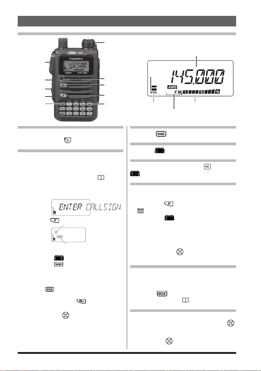
Cursol position (digit)
Quick Guide
Names and display of Controls
PTT Switch
DIAL Knob
Normal operation (VFO Mode
Operating Frequency
)
](
Microphone
[GM] key
[F] key
[BAND] key
37).
Volume Level S Meter / PO Meter
Communication Mode
Selecting the Operating Band
Press the key.
Tuning the frequency
Rotate the
.
Adjusting the volume
While pressing and holding the , rotate the
to adjust the volume to a comfortable level.
Adjusting the squelch setting
The squelch level may be adjusted to mute the
background noise when no signal is received.
MONI/T.CALL
Switch
VOL Switch
Power (Lock)
Switch
[MODE] key
Turning the Power ON
Install the charged battery pack and then
press and hold the
switch.
Inputting the Call sign
When turning the power ON for the first time
after purchasing, input the call sign of your
own station. Input call sign may be changed
from the Set Mode [64 MYCALL
1. When turning the power ON for the first
time after purchasing, the call sign input
screen will be displayed.
1. Press the key, and then press the
key.
2. Press the
.
Cursol
3. Input the call sign.
• Rotate the
• Press the
to select each character.
key to move the cursor
to the right.
4. Repeat step 3 to input the remaining
call sign characters.
• Press
key to move the cursor to
the left.
• Press and hold the
key to erase
all characters after the cursor.
(
5. Press the PTT
)
switch to conclude
inputting.
Normal operation (VFO Mode) screen
will be displayed
2. Rotate the
a level at which the background noise is
muted.
* When the squelch level is increased, the noise is more
likely to be silenced, but it may become more difficult to
receive weak signals.
3. Press the PTT
setting.
Selecting the Communication Mode
The communication mode is automatically
selected to correspond to the signal being
received.
Press the
communication mode
Transmitting/Receiving Signals
zTransmitting
While pressing and holding the PTT
switch, speak into the microphone.
zReceiving
to adjust the squelch to
(
)
switch to save the
key to manually select the
(
17).
Release the to return to receive mode.
2 FT-70DR/FT-70DE Operating Manual
(
)
Page 5
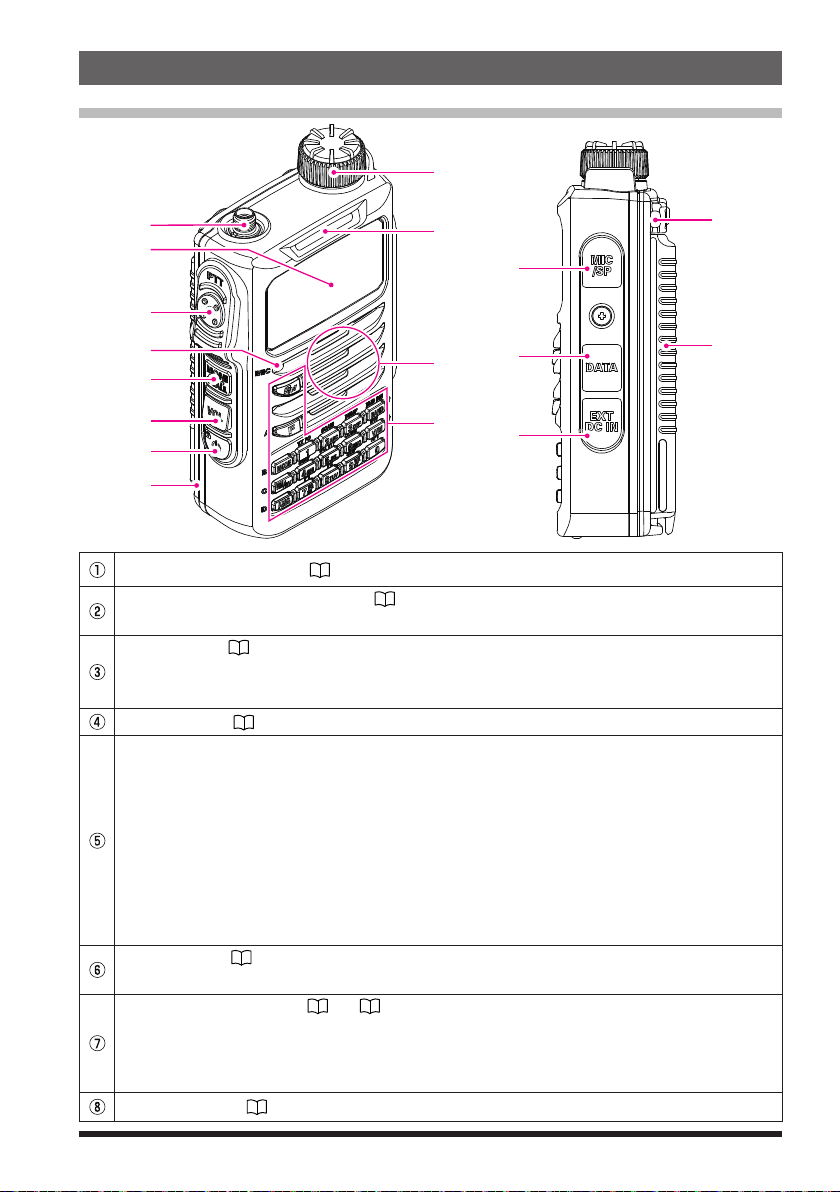
Transceiver
Controls & Connections
⑨
①
⑩
⑯
②
⑬
③
④
⑪
⑭
⑧
⑤
⑥
⑦
⑫
⑮
⑧
*
Antenna Jack (SMA
LCD (Liquid Crystal Display)
The display shows the current operating conditions.
PTT Switch
• Press and hold the PTT switch to transmit, and release it to receive.
• In the Set mode, press the PTT switch to save the new setting and return to normal operation.
Microphone
MONI/T.CALL Switch
USA/Asian version
Press the MONI/T.CALL switch to open the squelch.
European version
Press the MONI/T.CALL switch to activates the T-CALL(1750 Hz).
Regarding the current operating mode, both the analog FM and C4FM may monitor the received audio signal.
Press the [F] key → press the MONI/T-CALL switch and then rotate the DIAL
knob to adjust the squelch.
VOL Switch
While pressing and holding the VOL switch, rotate the DIAL knob to adjust the audio volume level.
Power (Lock) Switch
• When the power is OFF, press and hold this switch to turn the Power ON.
When the power is ON, press and hold the switch again to turn the Power OFF.
• When the power is ON, press this button briefly to engage, or release the key lock.
Battery pack*
(
(
(
)
)
17
)
17
)
14
(
)
12
(12
(
14, 18
)
(
)
6
)
3FT-70DR/FT-70DE Operating Manual
Page 6
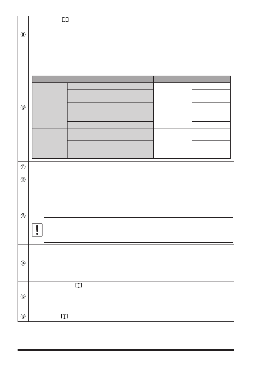
(
DIAL Knob
15
)
• Rotate the DIAL Knob to change the frequency or select a memory channel.
• While pressing and holding the VOL Switch, rotate the DIAL knob to adjust the
audio volume level.
• Rotate the DIAL Knob to select the desired entry for set mode.
MODE/STATUS Indicator
Indicates the transmit/receive status, and the communication mode with the high
brightness LED.
Communication status Left portion Right portion
Receiving
Transmitting
GM function
during opera-
tion
Analog FM mode
Digital C4FM mode Blue
Digital Data White
Receiving signals with unmatched DG-ID,
DP-ID, tone frequency or DCS code
Analog FM mode
Digital C4FM mode Blue
The other station is within the com-
munication range
Transmitting GM confirmation signal
to the other station within the communication range
Green
Red
-
Green
Blink in blue
Red
Light Blue
Blue
Speaker
Keypad
The functions of the keypad are described in detail on page 5.
MIC/SP jack*
• Connect a speaker microphone or earpiece microphone to this jack.
• Connect the optional Clone Cable (CT-27), to transfer saved data and function
settings to another FT-70DR/DE transceiver.
• Do not connect any microphone which is not specified by Yaesu.
A malfunction may can result.
• When an external microphone or cable is connected, the dust and splash protection does
not function.
DATA Terminal*
• When updating the firmware, connect to a PC using a USB cable.
* When a new firmware update for the FT-70DR/DE is available, download the
data from the YAESU website to update the FT-70DR/DE to the latest version.
* NOTE: the optional camera-equipped microphone (MH-85A11U) is not supported.
EXT DC IN Jack*(13
)
• When charging the battery pack, connect the battery charger to this jack.
• Connect an external power supply adapter with a cigarette lighter plug (SDD-13)
or an external power cable (E-DC-6) to this jack.
(
Strap Hole
*: When the included antenna and battery pack are installed and the MIC/SP jack, DATA terminal,
and EXT DC IN jack are securely covered with rubber caps, the FT-70DR/DE meets the waterproofing performance conforming to IP54.
12
)
4 FT-70DR/FT-70DE Operating Manual
Page 7
The Keypad Functions
Key
GM
MODE
HM/
RV
AMS
BAND
(
BND DN)
V/M
(
DW)
1
(
TX PO
2
(
SCAN
3
(
DTMF
4
(
STEP
5
(
SQ TYP
6
(
CODE
7
(P1)
8
(P2)
9
(
SKIP
0
(
RPT
Primary Function (Press Key
VFO or Memory Recall Inputting Memory Tag
Turns the GM (Group
Monitor) function
ON/OFF
Activates the “Secondary” key function
(
appears)
Selects the receive
mode between
FM(AM), DN and VW*
Press and hold this
key to erase all char
acters af ter the cursor
Press this key to
complete memory tag
in the Set Mode
Moves the cursor to
the left.
Reverses the transmit
and receive frequen
cies while working
-
-
through a repeater
Selects AMS Mode (TX
AUT/TX FM/TX DIG
Moves operation to
the next-highest frequency band
Switches between the
VFO mode and the
Memory Channel mode
Number “1” Number “1”
)
Number “2”
)
Number “3”
)
Numb er “4”
)
Number “5”
)
Number “6”
)
)
Moves the cursor to
the right
Press and hold this key
to complete the memory channel registration
Number “2”, or characters “A”, “B”, or “C”
Number “3”, or characters “D”, “E”, or “F”
Number “4”, characters “G”, “H”, or “I”
Number “5”, characters “J”, “K”, or “L”
Number “6”, or characters “M”, “N”,or “O”
-
Number “7”, or char-
Number “7”
acters “P”, “Q”, “R”, or
“S”
Number “8”
Number “8”, or characters “T”, “U”, or “V”
Number “9”, or char-
Number “9”
)
acte rs “ W ”, “X ”, “ Y ”,
or “Z”
Number “0”, or sym-
Number “0”
)
bols“(space)”, “-”, “/ ”,
“?”, or “!”
)
Secondary Func-
(
Press F + Key
-
Deactivates the “Secondary”key function
(
disappears)
Switches between the
frequency display and
the memory tag display
Recalls the “HOME”
(
favorite frequency)
channel
Activates the
WIRES-X feature
Moves operation to
the next- lowest frequency band
Enables the Dual Receive function
Selects the desired
transmit power output
level.
Starts the scanning
Selects the DTMF mode.
Selects the frequency
steps
Selects the squelch
types
Selects the CTCSS
Tone or DCS code
P1 (programmable
key 1
P2 (programmable
key 2
Selects the Memory
Scan “Skip” channel
or “Select” channel
Selects the direction of
the up link frequency shift
(
either “–”, “+”, or “simplex”)
during repeater operation.
tion
-
)
)
Third Function
(
Press and Hold for
)
over one second
Turns the GM (Group
Monitor) function
ON/OFF
Enters the Set mode.
Sets the DG -ID number
Overwrites the “HOME”
(
favorite frequency)
channel
Activates the AMS
feature
-
Activates the “Memory
Write” mode (for memory channel storage
Enters all the zeros at once
after entering the number “1”
on inputting the frequency.
Enters all the zeros at once
after entering the number “2”
on inputting the frequency.
Enters all the zeros at once
after entering the number “3”
on inputting the frequency.
Enters all the zeros at once
after entering the number “4”
on inputting the frequency.
Enters all the zeros at once
after entering the number “5”
on inputting the frequency.
enters all the zeros at once
after entering the number “6”
on inputting the frequency.
enters all the zeros at once
after entering the number “7”
on inputting the frequency.
enters all the zeros at once
after entering the number “8”
on inputting the frequency.
enters all the zeros at once
after entering the number “9”
on inputting the frequency.
enters all the zeros at once
after entering the number “0”
on inputting the frequency.
*: VW icon is displayed when Set Mode [16 DIG VW] ( 36) is set to “ON” (the default setting is “OFF”).
)
)
5FT-70DR/FT-70DE Operating Manual
Page 8
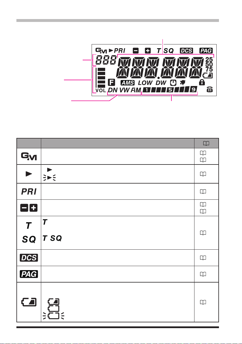
Display
Frequency / Memory Tag /
Communication Mode
DN: Normal digital mode
VW: Voice wide mode
FM: Analog FM mode
AM: AM mode (Receive only)
Memory Channel Number /
HOME Channel /
Memory Bank Number/
In Range / Out of Range
(GM function)
Volume Bar Graph
S Meter:Displays the received signal strength
PO Meter:Displays the transmit power level
Icon Description
Appears when the GM (Group Monitor) function in the digital
mode is enabled.
Set Mode Item
19
22
׃ Memory channel registered as a skip memory
׃
Memory channel registered as a specified memory (with blink
Priority Memory Channel 29
Repeater Shift Direction
Split Memory (a simultaneously
׃ Appears when the tone encoder function in the ana-
log FM mode is enabled.
׃ Appears when the tone squelch function in the ana-
log FM mode is enabled.
6 FT-70DR/FT-70DE Operating Manual
Appears when the DCS function in the analog FM mode is enabled.
Appears when the PAGER function is enabled. 34
The battery condition is displayed in 4 steps.
(
No display) ׃ Full battery power
׃ Enough battery power
׃ Battery is depleted. Charge battery.
׃ (When blinking) Charge battery immediately.
)
29
)
23
26
34
34
13
Page 9
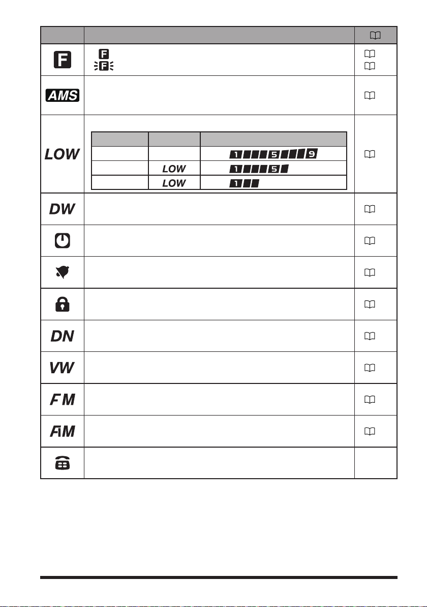
Icon Description
:
Appears
: On writing the memory channel, etc.
Appears
when the AMS (Automatic Mode Select) function is enabled. It is recommended that AMS function be enabled for normal operations.
TX Power Level Indicator (LOW/MID TX Power Selected
Tx Pow e r Icon TX Power Meter during transmission
HIGH (5 W
MID (2 W
LOW (0.5 W
)
when a function key is pressed.
)
)
(
No display
)
5
25
16
)
18
Appears
when the Dual Receive(DW) function is enabled.
Appears when the APO (Automatic Power-Off) function is enabled.
Appears when the bell function in the analog FM mode is enabled.
Appears
V/D mode (Normal digital mode
Voice FR mode (Voice wide mode
when the lock function is enabled. 18
)
)
29
35
36
17
17
Analog FM mode 17
AM mode (Receive only
DTMF Autodialer Active
)
17
–
7FT-70DR/FT-70DE Operating Manual
Page 10
Safety Precautions (Be Sure to Read
)
Be sure to read these important precautions, and use this product safely.
Yaesu is not liable for any failures or problems caused by the use or misuse of this product by the purchaser or any third party. Also, Yaesu is not liable for damages caused through the use of this product by
the purchaser or any third party, except in cases where ordered to pay damages under the laws.
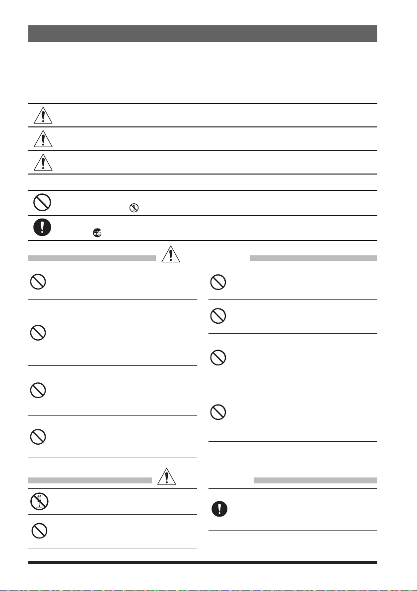
Types and meanings of the marks
DANGER
WARNING
CAUTION
This mark indicates an imminently hazardous situation, which, if not
avoided, could result in death or serious injury.
This mark indicates a potentially hazardous situation, which, if not
avoided, could result in death or serious injury.
This mark indicates a potentially hazardous situation, which, if not avoided, may result in minor or moderate injury or only property damage.
Types and meanings of symbols
These symbols signify prohibited actions, which must not be done to use this product
safely. For example: indicates that the product should not be disassembled.
These symbols signify required actions, which must be done to use this product safely. For
example,:
indicates that the power plug should be disconnected.
DANGER
Do not use this product in an area where RF
transmitters are prohibited, e.g., inside of a
hospital, airplane, or train.
This product can affect electronic or medical devices.
Do not transmit with this device while carrying or using a medical appliance such as a
cardiac pacemaker. When transmitting, use
an external antenna and keep as far as possible away from the external antenna.
The radio wave emitted by the transmitter can
cause the medical device to malfunction and
result in injury or death.
Do not transmit with this device in a crowded
place for the safety of persons using a medical device such as a cardiac pacemaker.
The radio wave emitted from this product can
cause the medical device to malfunction and
result in injury or death.
If thunder and lightening develop nearby
when an external antenna is used, immediate
ly turn this transceiver OFF, and disconnect
the external antenna from it.
A fire, electrical shock, or damage may result.
-
Do not use this product or the battery charger anywhere inflammable gas is produced.
A fire or explosion can occur.
Do not use this product while riding a bicycle
or driving a car. Accidents can result.
Be sure to stop the bicycle or car at a safe place
before using this product.
Do not touch any material leaking from the
LCD display or the battery pack with bare
hands.
The chemical may adhere to your skin or enter
your eye, and cause chemical burns. In such a
case, consult the doctor immediately.
Do not solder or short-circuit the terminals
of the battery pack.
A fire, leak, overheating, explosion, or ignition
may result.
Do not carry the battery pack together with a
necklace, hairpin, or small metal objects. A short
circuit can result.
WARNING
Do not disassemble or make any alteration
to this product.
An injury, electric shock, or failure may result.
Do not handle the battery pack or charger
with wet hands. Do not insert or remove
the power plug with wet hands.
An injury, leak, fire, or failure may result.
8 FT-70DR/FT-70DE Operating Manual
Keep the terminals of the battery pack
clean.
If terminal contacts are dirty or corroded, a
fire, leak, overheating, explosion, or ignition
can result.
Page 11
If smoke or a strange odor is emitted from
the main body, battery pack, or battery
charger, immediately turn the transceiver
off; remove the battery pack, and remove
the power plug from the outlet.
A fire, chemical leak, overheating, component
damage, ignition, or failure may result. Con
tact the dealer from which you purchased this
product or Yaesu Amateur Customer Support.
Do not bend, twist, pull, heat and modify
the power cord and connection cables in
an unreasonable manner.
This may cut or damage the cables and result
in fire, electric shock and equipment failure.
Do not pull the cable when plugging and
unplugging the power cord and connection cables.
Always hold the plug or connector when
unplugging; if not, a fire, electric shock and
equipment failure may result.
Do not use the device when the power
cord and connection cables are damaged,
or when the DC power connector cannot
be plugged in tightly.
Contact Yaesu Amateur Customer Support
or the retail store where this transceiver was
purchased for assistance, as this may result
in fire, electric shock and equipment failure.
Never cut the fuse holder off of the DC
power cord.
This may cause a short circuit and result in
ignition and fire.
Use only the specified type fuses.
Use of an incorrect fuse may result in fire and
equipment failure.
Do not install the front panel, the transceiver or the wire cables near the automobile
air bags.
In case of an accident, the transceiver may
interfere with air bag deployment and result
in extreme injury. The wire cables may also
cause the air bag to malfunction.
Do not power this transceiver with a voltage other than the specified power supply
voltage.
A fire, electric shock, or damage may result.
Do not make very long transmissions.
The main body of the transceiver may overheat,
resulting component failure or operator burns.
Do not place the transceiver in wet or damp
areas (e.g. near a humidifier).
-
This may result in fire, electric shock and
equipment failure.
Do not use DC power cords other than the
one enclosed or specified.
This may result in fire, electric shock and
equipment malfunctions.
When connecting a DC power cord, be certain the positive and negative polarities are
correct.
Reverse connection will result in equipment
damage.
When transmitting, keep the transceiver at
least 5.0 mm (3/16 inch) away from your body.
Use only the supplied antenna. Do not use
modified or damaged antennas.
Disconnect the power cord and connection
cables before installing separately sold accessory items, or replacing the fuse.
This may result in fire, electric shock and
equipment failure.
Follow the instructions provided when installing items sold separately and replacing
the fuse.
This may result in fire, electric shock and
equipment failure.
Use only the provided or specified screws.
Using screws of a different size, may result in
fire, electric shock and component damage.
Do not place the transceiver in a confined
space, such as a bookshelf which is not
ventilated well.
This may result in overheating and fire, electric
shock and equipment failure.
Do not operate the transceiver on a carpet
or a blanket.
This may result in overheating and fire, electric
shock and equipment failure.
If a foreign substance is spilled into the
transceiver, turn it OFF immediately and
remove the power plug from the outlet.
If used as it is, a fire, electrical shock, or damage may result.
CAUTION
Do not place the transceiver on an unsteady or sloping surface, or in a location
with extreme vibration.
The transceiver may fall or drop, resulting in
fire, injury and equipment damage.
Do not place this transceiver in a humid or
dusty place.
A fire or failure may result.
Do not use the transceiver near the radio
relay equipment.
Transmissions may affect radio communication.
Do not wipe the case using thinner and
benzene etc.
Use only a soft, dry cloth to wipe stains from
the case.
Do not throw the transceiver, or subject it
to strong impact forces.
Physical abuse may result in component damage and equipment failure.
If the transceiver will not be used for an
extended period, turn it OFF and remove
the battery pack for safety.
9FT-70DR/FT-70DE Operating Manual
Page 12
Keep magnetic cards and videotapes away
from the transceiver.
The data recorded on cash cards or videotapes may be erased.
Do not place this transceiver in direct sunlight or near a heater.
The case may be deformed or discolored.
Be sure to check with the manufacturer of
any hybrid or fuel-saving automobile re
garding use of the transceiver in that car.
Noise generated by an onboard electrical
device (inverter, etc.) can disrupt the normal
operation of the transceiver.
Do not operate the transceiver near the TV
or radio.
Radio disturbance can occur in the transceiv
er, the TV, or the radio.
Do not transmit near the television and radio.
Transmissions may cause electromagnetic
interference.
While transmitting, keep the antenna as far
from you as possible.
Long-time exposure to electromagnetic waves
may have a negative impact on your health.
Do not dangle or throw the transceiver by
holding its antenna.
This may injure others and may also result in
damage and failure of the transceiver.
-
-
Do not use the transceiver in a crowded place.
The antenna may strike others and result in an injury.
Keep this product out of the reach of children.
Injury to the child, or damage to the transceiv
er may result.
Do not use any products other than the
specified options and accessories.
Failure or miss operation may result.
Install the hand strap and belt clip securely.
Improper installation may cause the FT- 70DR/
FT-70DE to fall or drop, resulting in an injury
or damage.
This product has a waterproof structure
and conforms to “IP54” when the included
antenna and battery pack are installed and
rubber caps are securely attached to the
MIC/SP jack, EXT DC IN jack, and DATA
terminal. If this transceiver gets wet, dry it
with a soft cloth, do not leave it exposed to
the moisture.
Exposure to excessive moisture may degrade
the transceiver performance, shorten its life, or
cause a failure or electrical shock.
Before discarding a depleted battery pack,
affix tape or insulating covering to its terminals.
About Splash, Water, and Dust Resistant Features Conforming to IP54
When the included antenna and battery pack are installed, and the MIC/SP jack, EXT DC IN
jack and DATA terminal are securely covered with rubber caps, this product is dust and splash
resistant. To ensure continued Splash, Water, and Dust Resistant Features be sure to check the
following points before each use.
Check for damages, deterioration, and dirt.
r
Antenna rubber, key switch rubber, MIC/SP jack, EXT DC IN jack, DATA terminal rubber cap,
and battery pack seals.
Cleaning
r
Wipe with a dry soft cloth.
When this product is contaminated with seawater, sand or dirt, clean it with a soft damp cloth immediately.
Recommended maintenance interval
r
To insure continued optimal performance, it is recommended that maintenance be performed
annually, or when any damage or deterioration is found.
Note that the maintenance service is subject to fees.
Do not pour or immerse this product in the following liquids:
r
Sea, pool, hot spring, water containing soap, detergent, or bath additive, alcohol, or chemicals.
Do not leave this product for an extended time in a very humid location:
r
Bathroom, kitchen, or humid place.
Other precautions
r
Do not remove the rubber cap from the battery pack, the MIC/SP jack, the EXT DC IN jack,
or the DATA terminal when water drops have accumulated on the transceiver, or when it is
placed in a wet environment. This may result in water penetrating the transceiver, and causing equipment failure.
This product is not totally waterproof, and must never be immersed in water.
-
10 FT-70DR/FT-70DE Operating Manual
Page 13
About this manual
Reference icon symbols and conventions are used in this manual. Their meanings are described in the below chart.
Symbols Description
This icon indicates cautions and information that should be read.
This icon indicates notes, tips and information that should be read.
This icon indicates other pages containing relevant information.
This icon indicates FT-70DR/DE Advance Manual on the YAESU Website containing relevant
information.
• The settings at the time of purchase are referred to as the “default” or “default settings”.
• The names of Set Mode items displayed in the LCD, and the key names of the transceiver appear in bold characters.
Supplied Accessories and Options
Supplied Accessories
7.4 V, 1800 mAh Rechargeable Li-Ion Battery Pack
r
Battery Charger
r
SAD-11C/F/U*
Antenna
r
Belt Clip
r
zEnsure that the name of the dealer from which the transceiver was purchased, and the date of
purchase are indicated on the warranty card.
zIf any item is missing, contact the dealer from which the transceiver was purchased.
Operating Manual (this manual)
r
USB cable
r
SBR-24LI
SAD-18B*
1
2
Warranty Card
r
SBR-24LI Manual
r
Available Options
7.4 V, 1800 mAh Rechargeable Li-Ion Battery Pack
r
Battery Charger SAD-18B*
r
SAD-11C/F/U*
Rapid Charger SBH-28
r
DC Cable with and Cigarette-Lighter Plug SDD-13
r
DC Cable E-DC-6
r
Speaker / Microphone MH-34B4B r Earpiece Microphone SSM-57A
r
VOX Headset SSM-63A
r
BNC-to-SMA Adapter (BNCJ-SMAP) CN-3
r
Cloning Cable CT-27
r
*1 USA Version
*2
“B” suffix is for use with 120 VAC (Type-A plug), “C” suffix is for use with 230-240 VAC (Type-C plug),
“F” suffix is for use with 220 VAC, “H” suffix is for use with 220-230 VAC (Australian plug), and “U” suffix is for
use with 230 VAC (Type-BF plug).
Availability of accessories may vary. Some accessories are supplied as standard to meet local requirements, while others may be unavailable in some regions. Consult your Yaesu Dealer for details regarding these and any newly-available options. Connection of any accessory not approved
by Yaesu, should it cause damage, may void the Limited Warranty on this apparatus.
SBR-24LI
1
2
Microphone Adapter CT-44
r
Soft Case SHC-27
r
11FT-70DR/FT-70DE Operating Manual
Page 14
Preparation
Hold the thick base
of the antenna
Battery pack
connect
Lock
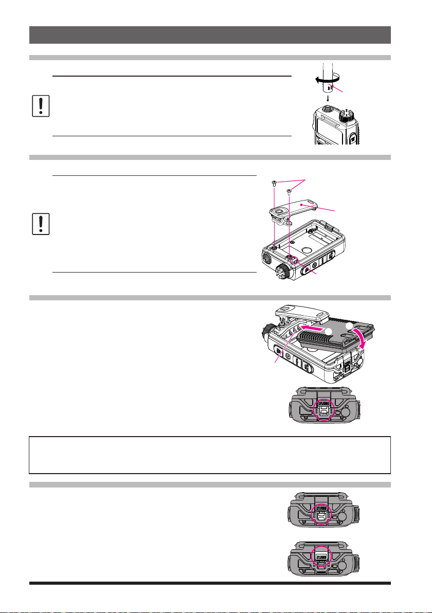
Installing the Antenna
1. Turn the antenna clockwise until it is secured.
zDo not hold or twist the upper part of the antenna when installing or
removing it. To do so may break the conductors inside the antenna.
zDo not key the transmit without installing the antenna. The transmitter
components may be damaged.
zWhen using an antenna other than the one supplied, or connecting to
an external antenna, ensure that the SWR is adjusted to 1.5 or lower.
Attaching the Belt Clip
1. Attach the belt clip on the back of transceiver using the supplied screws (two).
zBe sure to use the supplied screws when attaching the belt
clip. If any other screws are used, the belt clip cannot be
secured firmly to the battery pack and the transceiver may
drop off together with the battery pack; the transceiver and
battery pack may fall off, causing injury, breakage and other
damage.
zUse a hand strap which can withstand the weight of the
transceiver. If the hand strap is not strong enough, the it
may break and the transceiver may fall, causing injury,
breakage and other difficulty.
Installing the Battery Pack
(
1. Lift the belt clip outward
pack into the seals of the battery compartment on
the back of the transceiver.
2. Push the battery pack in until the battery latch
(
clicks securely
)
.
)
and Insert the battery
Supplied Screws
Belt Clip
Strap Hole for commercially
available strap
②
①
3. Slide the battery pack lock plate to the “UNLOCK”
position beside the battery latch until the entire
“LOCK” appears.
Caution
Risk of explosion if battery is replaced by an incorrect typ. Dispose of used batteries according to the
instructions.
Removing the Battery Pack
1. Slide the battery pack lock plate to the “UNLOCK”
position.
Unlock
2. Push the release button (PUSH) and tilt the Belt
Clip outward, and then remove the battery pack.
12 FT-70DR/FT-70DE Operating Manual
Page 15

Charging the Battery Pack
Charging the Battery Pack using the Battery Charger
Using the supplied battery charger (SAD-18B or SAD-11), it takes about 6 hours* to
charge the SBR-24LI battery pack fully.
*: Depending on the battery status, the charging time might be increased.
1. Turn the transceiver OFF to install the battery pack.
2. Referring to the figure at the right, connect the
battery charger plugs.
When the battery is being charged, the left side
of the MODE/STATUS Indicator lights red, and
“CHGING” is dislapyed.
3. When charging is completed, the display will
change to indicate “CHGFUL” and the MODE/
STATUS Indicator will light green.
zIn the USA Version, the MODE/STATUS Indicator is not lit when charging or when charging is complete.
zThe charging icon blinks, and charge progress is shown on the S/PO bar graph “ ”
meter during charging.
zWhen charging is completed, the charging is automatically ended.
zIf “CHGERR” appears on the LCD during the charging and the battery pack is not charged after a
lapse of 10 or more hours, stop charging the battery pack immediately. The battery pack is presumed
to be at the end of its service life, or defective. In this case, replace the battery pack with a new one.
zCharge the battery pack within the temperature range from +5 °C to +35 °C (+41 °F to +95 °F).
EXT DC IN
jack
Battery charger
SAD-18B/SAD-11
(Supplied)
Charging the Battery Pack using the Rapid Charger (SBH-28
)
For details on the Rapid Charger (SBH-28), see Optional SBH-28 manual.
● Approximate Operating Time and Remaining Charge Level Indication
Approximate operating time for the transceiver with the fully charged lithium-Ion battery pack (SBR24LI), and the indication of the remaining charge level of the battery is shown in the below table:
Frequency band Band in Use Charge Level Indication (Icon
(
144 MHz band Approx. 8 hours
430 MHz band Approx. 7 hours
The battery charge level calculations are based on an operating cycle of: Transmitting 6 seconds
(
5 W): Receiving 6 seconds (VOL Level 16): Stand By 48 seconds (RX SAVE 1:5
No display) ׃Full battery power
׃Enough battery power
׃Battery is depleted. Charge battery.
׃ (When blinking) Charge battery immediately.
)
)
The actual times the transceiver will operate as indicated in the above table, varies
depending on use, conditions, ambient temperature, etc.
External Power Supply
Connecting an External Power Supply for Use in Vehicle
The optional DC Cable with Cigarette-Lighter plug (SDD-13) allows power to be supplied
from a motor vehicle type cigarette lighter socket.
Connecting to an External Power Supply Using a Power Cable
The optional DC cable (E-DC-6) allows the transceiver to be connected to an external
DC power supply.
13FT-70DR/FT-70DE Operating Manual
Page 16

Operation
Turning the Transceiver ON
1. Press and hold the Power (Lock) switch to
turn the transceiver ON.
● Turning the transceiver OFF
Press and hold the Power (Lock) switch again
to turn the transceiver OFF.
● Inputting the call sign
The first time the transceiver is turned ON after it is purchased; input your own call sign.
zInputting characters
Input the callsign with the ten key or DIAL knob.
• Rotate the DIAL knob to select any of the 38
available characters:.
···
0
–
9 A
–
Z (space) -
* The ” - ” and ” / ” may not be input for the first
callsign character.
•
Press the keys repeatedly to toggle among the
four available characters associated with that
key. For example: pressing the [2] repeatedly
will toggle through A → B → C → 2 → A ···
zMoving the cursor and deleting the input characters:
[
BAND] key׃ Moves the cursor to the right
[
MODE] key׃ Moves the cursor to the left
[GM]
key׃ Press and hold to erase all characters after the cursor
zSaving the inputted call sign:
Press the [F] key or the PTT switch
zThe Call Sign ID can be changed using set mode item [64 MYCALL] ( 37).
Up to 10 characters can be entered.
zCharacters that may be inputted for the call sign are the numbers 0-9, letters ”A – Z” in upper
case, the hyphen and the slash.
*
*
/
···
Adjusting the Volume Level
1. While pressing and holding the VOL knob, rotate the DIAL knob to adjust the volume
to a comfortable level.
14 FT-70DR/FT-70DE Operating Manual
Page 17

Adjusting the squelch setting
The squelch level may be adjusted to mute the background noise when no signal is present.
1. Press the [F] key and then press the MONI/T-CALL switch.
“SQL
” (0 - 15) appear on the display.
□
2. Rotate the DIAL knob to adjust to a level at which the background noise is muted.
3. Press the PTT switch to save the setting.
zThe default setting is “SQL 1”
zWhen the squelch level is increased, the noise is more likely to be silenced, but it may become
more difficult to receive weak signals.
Selecting a Frequency Band
1. Press the [BAND] key to select the desired
frequency band.
Frequency ranges for each frequency band are below:
AIR band
108
137 MHz 137
-
Press the [F] key, then press the [BAND] key to switch the frequency bands in reverse order.
144 MHz band 430 MHz band
174 MHz 174
-
Information
radio band (1
222 MHz 222
-
)
Information
radio band (2
420 MHz 420
-
)
470 MHz 470
-
Information
radio band (3
580MHz
-
)
Tuning to a Frequency
● DIAL knob
By pressing the [F] key and then rotating the DIAL knob, the frequency will change in
1 MHz steps.
● The numeric keys
Press the numeric keys to enter the frequency digits in order, beginning with the
100 MHz digit.
Examples:
To enter 145.520 MHz, press [1] → [4]→ [5] → [5] → [2] → [0
To enter 400.000 MHz, press [4] → [0] (press and hold); or [4] → [V/M
]
]
When entering a frequency using the numeric keys, it may be canceled by pressing the PTT switch.
Changing the Frequency Step
The DIAL knob rotation frequency step may be changed. Normally, the factory default
setting will provide a good frequency step.
1. Press the [F] key and then press the [4] (STEP) key, and rotate the DIAL knob to
change the frequency step.
2. Press the PTT switch to save the setting and return to normal operation.
In the default setting, of the frequency step is set to “AUTO”, which automatically provides a
suitable frequency step according to the frequency band.
15FT-70DR/FT-70DE Operating Manual
Page 18

Selecting the Communication Mode
(
Using AMS
The FT-70DR/DE transceiver is equipped with the AMS (Automatic Mode Select) function which automatically selects the communication mode corresponding to the received
signal.
1. Press and hold the [AMS] key to turn the
AMS function ON or OFF.
When the AMS function is turned OFF, the
communication mode must be selected manually. See
Mode
The selected communication mode is displayed
under the AMS icon.
●Setting the transmission mode when using the AMS function
The AMS function will automatically set the receiver to the mode of the received signal,
but the transmission mode may be fixed regardless of the received mode.
1. Press the [AMS] key.
2. Rotate the DIAL knob to tune to the desired transmission mode as follows.
Automatic Mode Select) function
(
Fixing the Communication
"
)
".
AMS icon
Current Communication Mode
zThe default setting is “ON” in the AMS function.
zAMS function may only be turned ON when operating within the 144 MHz and 430 MHz
Amateur Bands
Transmit Mode Receive and Transmit
TX AUT
(
TX AUTO
TX FM
TX DIG
(TX DIGITAL)
Receive׃ Automatically selects the communication mode of transmission
Transmit: Transmits automatically in the communication mode selected
)
Receive׃ Automatically selects the communication mode of transmis-
Transmit׃ Always transmits in the analog FM mode.
Receive׃ Automatically selects the communication mode of transmission
Transmit׃ Always transmits in the DN mode.
according to the signal being received.
by the AMS function, or in the mode selected manually by
pressing the [MODE] key.
sion according to the signal being received.
according to the signal being received.
3. Press the [AMS] key or the PTT switch to save the setting and return to normal operation.
When the AMS function is ON, press the [MODE] key to change the communication mode temporarily.
16 FT-70DR/FT-70DE Operating Manual
Page 19

Fixing the Communication Mode
Mode/Status indicator
1. To fix the transmit operation mode, press and
hold the [AMS] key to turn the AMS function OFF.
The “AMS” icon turns off.
2. Press the [MODE] key to change the commui-
Current Communication Mode
cation mode.
Communication Mode Icon Description of Modes
V/D Mode
(
Voice/Data simultaneous
transmission mode
Voice FR Mode
(
Voice Full Rate Mode
)
*1
)
This is the standard digital mode.
Calls are less prone to interruptions caused by detection and
correction of the received digital voice signal.
1
High speed data communication using entire 12.5 kHz band.
*
Enables high-quality voice communication.
FM Mode
AM Mode (receive only
[
*1 When the Set Mode
*2 When the Set Mode
the AIR band (108 - 136.995 MHz).
16 DIG VW
[
47 RX MOD
*2
)
] (
36) is set to “ON” (factory default is “OFF”), the Voice FR mode (VW) may be selected.
] (
37) is set to “AUTO” (factory default setting), AM mode is automatically selected within
Analog communication using FM mode.
The AM mode for receive only.
Transmission
1. While pressing and holding the PTT switch,
speak into the microphone.
The MODE/STATUS Indicator lights during the
transmission.
Transmission mode
Analog FM
Digital C4FM mode Blue
If the PTT switch is pressed when a frequency other
than the amateur ham radio band is selected, an
alarm tone (beep) will be emitted and “ERROR”
appears on the LCD, disabling transmission.
Left
portion
Red
2. Release the PTT switch to return to receive mode.
When receiving a signal, the MODE/STATUS
Indicator lights according to the receive mode.
Receive mode
Analog FM
Digital C4FM mode Blue
Left
portion
Green
Right
portion
Red
Right
portion
Green
Microphone
If transmission is continued for a long period, the transceiver overheats and the high temperature
protection function is activated. As a result, the transmitting power level is automatically set to Low
Power. If transmission continues while the high temperature protection function is active, the transceiver
will be forcibly returned to the receive mode.
17FT-70DR/FT-70DE Operating Manual
Page 20

Changing the Transmission Power Level
1. Press the [F] key, then press the [1](TX PO) key.
2. Rotate the DIAL knob to select one of the following transmission power levels.
TX PO Level Icon PO meter
(
HIGH (5 W)*
MID (2 W
LOW (0.5 W
)
)
off
)
*The default setting.
3. Press the PTT switch to save the setting and return to the normal operation.
The transmission power level may be set separately for each frequency band.
Locking Keys and DIAL knob
1. Press the [POWER] (LOCK) switch, “LOCK”
is displayed on the LCD for one second, the
“
” icon appears on the LCD, and then the
keys and DIAL knob are locked.
z The keys, the DIAL knob, and the PTT switch may be selected to be locked using Set Mode
[
30 LOCK
The default setting is the [K+D] (the keys and the DIAL knob are locked).
zThe [MONI/T-CALL] switch and the VOL switch cannot be locked.
(
]
36).
2. Press the [POWER] (LOCK) switch again, “UNLOCK” will be displayed on the LCD
and keys and the DIAL knob are unlocked.
Programmable key function
The [7] (P1) and or the [8] (P2) keys are user programmable, allowing quick access to
the Set Modes that are used most often.
● Assigning Set Mode Items to the Programmable Keys
1. Press and hold the [F] key, and then rotate the DIAL knob to select the desired Set
Mode item.
2. Press and hold the [7](P1) key or the [8](P2) key.
“P1KEY” or “P2KEY” appears on the LCD and return to the Set Mode.
3. Press the PTT switch to return to the normal operation.
● Recalling the assigned Set Mode item
1. Press the [F] key and then press the [7](P1) key or [8](P2) key.
The assigned Set Mode item appears on the LCD.
The [7] (P1) is [12 DC VLT] ( 36) and [8] (P2) key is [47 RX MOD] ( 37) as a default
assignment.
18 FT-70DR/FT-70DE Operating Manual
Page 21

Using the convenient Digital C4FM feature
About the Digital Group ID (DG-ID) feature
1. Digital Group ID (DG-ID) function allows communications with only the specific group
members using the two-digit ID numbers. The desired DG-ID number from 00 to 99 is
set in advance by all the group members. This ID number may be set separately for
transmit and receive, when the same ID number is set for both transmit and receive,
only group members with the same ID number will be heard. This feature may be used
to communicate only with group members that have the same DG-ID number. The GM
function may also be utilized to automatically monitor whether or not group member
stations with the same DG-ID number are operating within communication range.
The DG-ID number 00 detects signals with all ID numbers. Normally setting the ID
number to “00” for both transmit and receive will permit reception of the signals from
all other stations using the digital C4FM mode, regardless of the transmit DG-ID
number settings of the other stations.
Also note that when the receive DG-ID number of your transceiver is set to a DG-ID
number other than “00”, received signals that do not have the same DG-ID number
may not be heard.
2. When accessing the C4FM digital repeater controlled by the DG-ID number, set the
transmit DG-ID number of the FT-70DR/DE to that of the repeater input. Even in that
case, if the receive DG-ID number of the FT-70DR/DE is set to “00”, all the downlink
signals from the repeater may be received.
Communicating with the DG-ID feature
zDigital C4FM mode transceivers compatible with the DG-ID function are required in order to
utilize this function.
zIf the firmware is not compatible with the DG-ID function, update the latest firmware to use the
DG-ID function. The latest firmware is available on the YAESU website.
Setting the transmit and receive DG-ID number to “00” for communicating with all other stations using C4FM digital mode
1. Press and hold the [MODE] key.
• The DG-ID number setting screen appears and the
transmit DG-ID number “T00” blinks.
• If the transmit DG-ID number is not set to “T00”, rotate
the DIAL knob to set “T00”.
2. Press to the [MODE] key again and the receive DG-ID
number “R00” will blink.
If the receive DG-ID number is not set “R00”, rotate the
DIAL knob to set “R00”.
3. Press and hold the [MODE] key, or press the PTT switch to save the setting and return to the normal operation.
The setting is complete.
19FT-70DR/FT-70DE Operating Manual
Page 22

4. To check whether or not other stations are operating within communications range,
press the [GM] key to turn the GM (Group Monitor) function ON.
• The other stations also need to turn the GM (Group Monitor) function ON.
• While operating with the GM (Group Monitor) function, “Operating Frequency”,
“GROUP” and “DG-ID number” are shown repeatedly on the LCD.
5. Press the [GM] key to turn the GM (Group Monitor) function OFF and return to the normal operation.
zWhile setting the DG-ID number, pressing and holding the [HM/RV] key will set the transmit
and the receive DG-ID numbers to “00”.
zIf the receive DG-ID is set to a number other than “00”, only signals with that DG-ID will be
received. Normally, set the receive DG-ID number to “00” except when communication is
desired only with group members.
zThe transmit and receive DG-ID default number is set to “00”.
Communicating only with the specific members by setting the DG-ID number except for “00”
Example Set the DG-ID number of to “50”
1. Press and hold the [MODE] key.
• The DG-ID number setting screen appears and the
transmit DG-ID number “T00” blinks.
• Rotate the DIAL knob to set the transmit DG-ID num-
ber to “T50”.
2. Press to the [MODE] key again to blink the receive DGID number “R00”.
Rotate the DIAL knob to set the reception DG-ID number to “R50”.
3. Press and hold the [MODE] key or press the PTT switch to save the setting and return to normal operation.
Tuning to the same frequency and setting the same DG-ID for all the group members
will enable communication between the members and exclude other signals.
4. Press the [GM] key to turn the GM (Group Monitor) function ON and check whether or
not other stations that are operating on frequency, with the GM (Group Monitor) func
-
tion ON, and have the same GD-ID number setting, are in the communication range.
• The other stations also need to turn the GM (Group Monitor) function ON.
• During operating on the GM (Group Monitor) function, “Operating Frequency”,
“GROUP” and “DG-ID number” are shown repeatedly on the LCD.
5. Press the [GM] key to turn the GM (Group Monitor) function OFF and return to the normal operation.
zWhile setting the DG-ID number, pressing and holding the [HM/RV] key will set the transmit
and the receive DG-ID numbers to “00”.
zIf the receive DG-ID is set to a number other than “00”, only signals with that DG-ID will be
received. Normally, set the receive DG-ID number to “00” except when communication is
desired only with group members.
20 FT-70DR/FT-70DE Operating Manual
Page 23

For example, if the transmit and receive DG-ID numbers of group members are all set to "50",
DG-ID
T50 (transmit
)
R50 (receive
)
DG-ID
T50 (transmit
)
R50 (receive
)
The group member set the DG-ID number to “50”
Only group members set to the same DG-ID
number may communicate.
Setting the receive DG-ID number to
“00” , all the C4FM digital stations
may be received signals
DG-ID
T00 (transmit
)
R00 (receive
)
DG-ID
T00 (transmit
)
R00 (receive
)
DG-ID
T90 (transmit
)
R90 (receive
)
The other station set the receive DG-ID
number to the number except for “00”
may not received the signals that is not
matching the DG-ID number.
communications from other DG-ID numbers is not received and only the group members setting
the same DG-ID numbers may communicate. Also, the other stations set the receive DG-ID to any
number except for "00" may not be received the signals of your stations.
About the GM(Group Monitor) feature
The GM (Group Monitor) function automatically checks to find if there are any stations
with the GM function in operation with the same DG-ID number within communication
range. Setting the receive DG-ID number to “00” will check for all the C4FM digital stations In/Out of range.
zActivating the GM (Group Monitor) function, the Digital C4FM
mode is changed. For communicating in the Analog FM mode,
Set the GM function OFF.
zThe other member stations must also turn the GM (Group
Monitor) function ON.
GM icon
In/Out indication
When the GM (Group Monitor) is activated, the following information screens are automatically switched.
GM information screen
Group Mode Display
*
1
:Memory tag display is displayed in the case of the memory channel or the home channel setting the memory tag.
(Automatically switching display)
Memory Tag Display
*1
Frequency DisplayOwn DG-ID Number Display
21FT-70DR/FT-70DE Operating Manual
Page 24

● In / Out Display
• When another station with the same DG-ID number is within the communication
range, a beep sounds and the "In" is displayed under the GM (Group Monitor)
function icon, and the right side of the MODE/STATUS indicator lights in light blue.
• When all the members are out of the communication range, "out" is displayed and the
MODE/STATUS indicator light is off.
• When a signal from another member station is received, the call sign of the other sta-
tion is displayed on the LCD for about 10 seconds.
When the DG-ID transmit and receive are set to "00" in the factory default setting, all stations In/
Out of range may be received and are displayed, but the other stations that set their receive DGID number to other than "00" may not be receiving your signals.
Displaying the information of the other station received by GM (Group Monitor) function
1. When receiving the signals with the same DG-ID number, press the [MODE] key to
reveal the other station information:
• Depending on the model, the information such as the call sign of the other station,
latitude, longitude and so on may be displayed.
• When receiving the signals of multiple stations, press the [MODE] key to display
the call sign of the other station, and then rotate the DIAL knob to select the other
stations to be displayed on the LCD.
• Up to 24 stations may be displayed in order of their reception.
zThe FT-70DR/DE may not send its own location information because the FT-70DR/DE is not
equipped with the GPS function.
zThe position information is displayed only when the latitude and longitude information is
included in the signal of the other station.
zThe transceivers that may transmit position information with the GM function are as follows: (As of Nov. 2017).
FTM-400XD / FTM-400D series, FTM-100D series, FT2D, FT1XD, FT1D, FT-991A / FT-991*
(
*: Latitude and longitude setting must be entered manually, or an external GPS device must be connected.).
GM information screen
(Automatically switching display)
Group Mode Display
Call Sign 1 Call Sign 2
Latitude
Longitude
Switch by the [MODE] key
Select by the DIAL konb Select by the DIAL konb
Switch by the [MODE] key
2
*
Switch by the [MODE] key
2
*
Switch by the [MODE] key
Memory Tag Display*1Frequency DisplayOwn DG-ID Number Display
Call Sign 24
1:Memory tag display is displayed in the case of the
*
memory channel or the home channel setting the
memory tag.
2:
the Latitude and longitude are displayed only when position
*
information is included in the signal of the other station.
When the callsign or latitude/longitude is being displayed, the displayed station is given priority. So
even when another station is received the display is not changed. While using the callsign display
screen, rotate the DIAL knob to select another station display.
22 FT-70DR/FT-70DE Operating Manual
Page 25

Repeater Operation
Repeater shift icon
Tone encoder icon
Communicating Via the Repeater
The transceiver includes an ARS (Automatic Repeater Shift) function which sets the repeater operation automatically when the receiver is tuned to the repeater frequency.
1. Set the downlink (output) frequency from the repeater.
2. “
”, “ ”or “ ” lcons may automatically appear
above the frequency.
3. Speak into the microphone while pressing and
holding the PTT switch.
● The reverse state
The “reverse” state temporarily reverses the transmit and receive frequencies. This
allows checking to find if direct communication with the other station is possible.
1. When the ARS in ON, press the [HM/RV] key.
• The transmit and receive frequencies are tem-
porarily reversed (“reverse” state).
• In the “reverse” state, the “
the LCD.
2. Press the [HM/RV] key to exit from the “reverse” state.
zThe repeater settings may be changed from the Set Mode.
Set Mode [46 RPT.FRQ]: Allows changing the repeater shift offset.
[F]
key → [0] (RPT) key: Allows setting the repeater shift direction.
[F]
key → [6] (CODE) key: Allows setting the tone encoder frequency.
zThe ARS function may be set to OFF in the Set Mode [45 RPT.ARS].
” or “ ” blinks on
The Yaesu DR-2X/XE repeater incorporates the DG-ID feature, which may limit
access to the repeater by using a two-digit 01 to 99 ID number. Multiple DR-2X/XE
repeaters, connected via the Internet may also be managed using the DG-ID numbers. To access a specified DR-2X/XE repeater, or DR-2X/XE repeater group, that
requires a DG-ID, the FT-70DR/DE transmit DG-ID must be set/programmed accordingly. Also, when communicating via a DR-2X/XE repeater, set the receive DGID number to “00”.
Tone Calling (1750 Hz burst tone
)
If your transceiver is FT-70DE (European version), press and hold in the MONI/T-CALL
switch to generates the 1750 Hz burst tone to access the European repeater.
The transmitter will automatically be activated, and the 1750 Hz audio tone will be superimposed on the carrier. Once the repeater has been accessed, release the MONI/
T-CALL switch, and use the PTT switch to activate the transmitter thereafter.
If needed, the FT-70DR (USA/Asian version), may be set to access repeaters which require a 1750 Hz burst tone by setting the MONI/T-CALL switch to serve as a “Tone Call”
switch instead. To change the configuration of the MONI/T-CALL switch, use Set Mode
[
32 M/T-CL
] (
37).
23FT-70DR/FT-70DE Operating Manual
Page 26

Using the Memory
The FT-70DR/DE transceiver incorporates Large-capacity memory channels that can register the operating frequency, communication mode, and other operational information.
• 900 Memory Channels
• 90 Skip Search Memory Channels
6 Home Channels
•
50 pairs PMS Memory Channels
•
Each memory channel can store the following information.
• Operating frequency • Communication mode • Frequency steps
• TX output power • Memory tag • Repeater information
• Tone information • DCS information • ATT information
• S
-
Meter squelch level • Skip memory information • Specified memory channel
information
Memory channels can be sorted and registered into memory banks according to the desired use. The transceiver allows using 24 different memory banks. A maximum of 100
memory channels can be registered in each memory bank. One memory channel
can be registered to several memory banks. One memory channel in one memory bank
can be recalled, and the memory channels in the several memory banks can be scanned.
Memory Channel Configuration of the Transceiver
Memory channels
900 channels
(
Skip search memory channels
)
(99 channels)
PMS memory channels
(50 sets)
4
3
2
1
Home channels
(6 channels)
900
899
904
903
902
901
Up to 100 memory channels can be
(One memory channel can be registered
999
998
Memorybanks
(24banks)
registered to each bank.
to several memory banks
L50/U50
L49/U49
L4/U4
L3/U3
L2/U2
L1/U1
)
For additional details on the Skip Search Memory, PMS memory channel and Memory Bank,
refer to the Advanced Manual which may be downloaded from the Yaesu website.
CAUTIONS!
The information registered to memor y channels can be corrupted by incorrect operation, static
electricity, or electrical noise. Also, it can be erased in the event of a failure or repair. Be sure to
keep a record of the settings on paper.
24 FT-70DR/FT-70DE Operating Manual
Page 27

Registering to Memory Channels
Memory Channel
1. Set the frequency and the communication mode
to be registered to a memory channel.
2. Press the [V/M] key.
“
” blinks on the LCD.
3. Rotate the DIAL knob to select the desired
channel number.
The channel numbers that do not contain memory data will blink on the LCD.
4. Press the [V/M] key.
• If you attempt to register a frequency to a
memory channel that already contains frequency data, “M-WRT?” will appear on the
LCD. Press the [V/M] key to overwrite the
Number
memory channel.
• The memory tag input screen will be displayed on the LCD.
5. Input the memory tag.
• Use the numeric keys or the DIAL knob to in-
put the characters.
• Example: Rotating the DIAL knob to display the following characters.
A - Z (symbol) 0 - 9 (symbol) A - Z
• Example:
Press the [2] key repeatedly to toggle among the following available characters.
A → B → C → 2 → A
···
• Moving the cursor and deleting the input characters
[
BAND] key: Moves the cursor to the right
[
MODE] key: Moves the cursor to the left
[GM]
key (press and hold): Erases all characters after the cursor
6. Press and hold the [V/M] key.
The beep sounds and the memory is saved.
Recalling a Memory Channel
1. Press the [V/M] key.
The memory channel most recently used appears on the LCD.
2. Rotate the DIAL knob to select the desired memory channel, or input the 3 digits of
the memory channel using the numeric keys to recall the memory channel directly.
3. Press the [V/M] key to exit the memory mode, and return to the normal operation.
zThe data registered to a memory channel can be transferred to the VFO operating band by
following the procedure below:
Press and hold the [V/M] key Rotate the DIAL knob to select the channel Press and hold
the [GM] key “V-WRT?” appears Press the [GM] key.
zPressing the [F] key and then rotating the DIAL knob allows skipping memory channels quickly
in steps of 10 memory channels.
zThe transceiver may be placed into a Memory Channel Only mode, (which restricts the FT-70DR/DE
to operate only on the memory channels), by pressing the [V/M] key, while pressing the Power (Lock)
switch to turn the transceiver ON. To cancel the Memory Channel Only mode, turn the transceiver
OFF, then press the [V/M] key again, while pressing Power (Lock) switch to turn the transceiver ON.
25FT-70DR/FT-70DE Operating Manual
Page 28

Clearing Memories
Home channel
1. Press the [V/M] key to enter the memory mode.
2. Press and hold the [V/M] key.
3. Rotate the DIAL knob to select the memory channel from which the data is to be cleared.
4. Press the [AMS] key.
5. Confirmation screen “M-MSK?” is displayed and
then press the [AMS] key again to clear the memory channel.
z Data on memory channel One, and the Home channel may not be cleared.
zThe cleared memory can be restored using the following steps.
Press the [V/M] key to enter the memory mode
DIAL knob to restore the channel Press the [AMS] key
Press and hold the [V/M] key Rotate the
Recalling the Home Channels
1. Press the [F] key, and then press the [HM/RV]
key.
“H” and the home channel frequency of the currently selected band appears on the LCD.
2. Press the [F] key, and then press the [HM/RV]
key or the [V/M] key to return to the previous frequency.
While recalling the home channel, rotate the DIAL knob to transfer the home channel frequency
to the VFO operating band. The home channel frequency can be set not to be transferred in the
Set Mode [27 HM-VFO
] (36)
.
indication
Changing the Home Channel Frequency
1. Set the frequency and the operating mode you want to store as a home channel.
2. Press and hold the [HM/RV] key.
The beep sounds and the home channel frequency is changed.
For additional details on the following functions, refer to the Advanced Manual which may be
downloaded from the Yaesu website.
Split Memory
Two different frequencies, one for receive and another for transmit, can be registered to
a memory channel.
Using Memory Tag
Memory name tags may be assigned to the memory channels and home channels.
Using Memory Bank
The transceiver allows using up to 24 memory banks to allow sorting and registering the
channels in convenient groups.
26 FT-70DR/FT-70DE Operating Manual
Page 29

Scanning Function
The transceiver supports the following four scanning functions:
• VFO Scan
• Memory Channel Scan
• Programmable Memory Scan(PMS
• Memory Bank Scan
• Weather Alert Scan
For additional details on the Programmable Memory Scan (PMS) and Memory Bank Scan, refer
to the Advanced Manual which may be downloaded from the Yaesu website.
VFO Scan
VFO scan function scans the frequencies, and detects signals.
1. Press the [V/M] key to enter the VFO mode.
2. Press the [F] key and then press the [2](SCAN) key.
• Scanning starts toward higher frequencies.
• If the DIAL knob is rotated while scanning is
in progress, the scanning will continue up or
down in frequency according to the direction
of the DIAL Knob rotation.
• If the scanner halts on an incoming signal, the back light will turn ON and the decimal point
between the “MHz” and “kHz” digits of the frequency display will blink. Scanning will resume in about five seconds.
3. Press the PTT switch to cancel the scanning.
zIf the scan has paused on a signal, rotating the DIAL knob will cause scanning to resume instantly.
zThe manner in which the scanner resumes after it has paused on a signal may be selected within
approx. 0.1 sec - 10 sec by using the Set Mode [53 SCN.STR] (37).
zWhen turning the transceiver OFF while scanning, turning the transceiver ON, will cause scanning to resume.
zTo set the transceiver action when scanning stops, see “Setting the Receive Operation When
Scanning Stops” on page (37).
zThe following Set Modes allow scanning only the frequencies within the set band frequency range.
The Set Mode [49 SCM.WTH] the frequency range on memory scanning (37).
The Set Mode [50 SCV.WTH] the frequency range on VFO scanning (37).
)
Memory Channel Scanning
The receiver may be set to scan memory channels:
1. Recall a memory channel to begin memory scanning.
2. Press the [F] key and then press the [2](SCAN) key.
• Scanning starts toward higher memory channel numbers.
• If the DIAL knob is rotated while scanning is in progress, the scanning will continue up or down in frequency according to the direction of the DIAL Knob rotation.
• If the scanner halts on an incoming signal, the back light will turn ON and the decimal point
between the “MHz” and “kHz” digits of the frequency display will blink. Scanning will
resume in about five seconds.
3. Press the PTT switch to cancel the scanning.
If the scan has paused on a signal, rotating the DIAL knob will cause scanning to resume next
memory channel.
27FT-70DR/FT-70DE Operating Manual
Page 30

Setting the Receive Operation When Scanning Stops
1. Press and hold the [F] key to enter the Set Mode.
2. Rotate the DIAL knob to select the Set Mode [52 SCN.RSM].
3. Press the [F] key.
4. Rotate the DIAL knob to select the operation performed after the scan stops:
• 2.0 S - 10.0 S
The signal is received for a specified period of time, and then scanning resumes.
The scan resume time may be set from 2 to 10 seconds at 0.5 second intervals.
• BUSY
The signal is received until the signal fades out. Two seconds after the signal fades
out, scanning resumes.
• HOLD
Scanning stops and tuning remains on the current receive frequency (Scanning
does not resume).
5. Press the PTT switch to save the new setting and exit to normal operation.
zThe above setting (Set Mode [52 SCN.RSM
zThe time interval to resuming scanning after a received signal ends during scanning may be
set between approx. 0.1 SEC to 10 SEC (the factory default is set to 2.0 SEC.) in the Set Mode
[
53 SCN.STR
] (37)
.
] (37))
is common for all scanning operation.
Weather Alert Scan
This feature allows you to check the Weather Broadcast Memory Channels for the presence of the NOAA Alert Tone while operating using VFO scan or Memory channel scan.
When the Weather Alert Scan feature is engaged, the FT-70DR/DE will check the
Weather Broadcast Channels for activity every five seconds while scanning. If you watch
the display carefully, you'll observe the scanner periodically shifting to the Weather
Broadcast channel, scanning the Weather channels quickly in search of the Alert Tone,
after which regular scanning will resume for another five seconds.
1. Press and hold the [F] key to enter the Set Mode.
2. Rotate the DIAL knob to select the Set Mode [61 WX ALT]
(
37).
3. Press the [F] key and then rotate the DIAL knob to select "ON".
4. Press the PTT switch to save the setting and return to normal operation.
5. Press the [F] key and then press the [2](SCAN) key to start scanning.
• Scanning starts searching upwards in frequency.
• The display will remain on the VFO frequency, but every five seconds the transceiver
will scan the Weather Broadcast Channels
for activity.
28 FT-70DR/FT-70DE Operating Manual
Page 31

6. While scanning the Weather channels, press
the PTT switch and then press the PTT switch
again.
• Scanning starts within the Weather Broadcast
Channels.
• While scanning the Weather channels, press
the PTT switch and then rotate the DIAL
knob to select the desired Weather Broadcast
Channel.
7. Press the [V/M] key return to normal operation.
For additional details on the following functions, refer to the Advanced Manual which may
be downloaded from the Yaesu website.
CH
A1 162.550 MHz
A2 162.400 MHz
A3 162.475 MHz
A4 162.425 MHz
A5 162.450 MHz
A6 162.500 MHz
A7 162.525 MHz
A8 161.650 MHz
A9 161.775 MHz
A10 163.275 MHz
Frequency
Skip Memory Channel and Specified Memory Channel
Two types of memory channels may be designated, “skip memory channels” and “specified memory channels” for effective memory channel scanning.
Skip memory channels: Permits designating undesired channels to be skipped during
scanning. Alternatively, you can specify that only designated memory channels are
scanned during memory scanning.
Programmable Memory scan (PMS
)
This function scans only the range of frequencies between the lower and upper limits
registered in a pair of PMS Programmable Memory channels. 50 sets of PMS memory
channels (L1/U1 to L50/U50) are available.
Dual Receive (DW) feature
The transceiver checks for signals on the frequency registered to the selected memory
channel (Priority Memory Channel) once approximately every 5 seconds.
29FT-70DR/FT-70DE Operating Manual
Page 32

Using the WIRES-X Function
WIRES-X feature
WIRES (Wide-coverage Internet Repeater Enhancement System) is an Internet communication system which expands the range of amateur radio communication.
You may employ Internet communications by connecting from your transceiver to a
WIRES-X local node station.
FT-70DR/DE does not accommodate the transmission/reception of messages, images, audio
messages, or location information.
Connecting to a WIRES-X node in the C4FM mode (*Recommended)
zAscertain the DSQ code or the DG-ID setting of the WIRES-X node station. Connecting to
the WIRES-X node requires the transceiver DG-ID be set according to the DSQ code or the
DG-ID code set on the WIRES-X node station.
zConfirm that the operating mode of WIRES-X node has been set to the C4FM digital mode.
1. Set the transmit/receive DG-ID to the same ID number as the local node station.
For more details on the DG-ID number, see “Communicating with the DG-ID feature”
on page 19.
2. Transmit on the corresponding transmit/receive frequency.
• If the signal is received from the node, continue to transmit using the DG-ID setting
as is.
• If the signal is not received from the node.
Connecting to the other node ID or the other room ID
1. Press and hold the [F] key to enter the Setup Menu.
2. Rotate the DIAL knob to select “63 W-DGID”, then press the [F] key.
3. Rotate the DIAL knob to set the WIRES-X DG-ID to the same ID number as the local
node station.
Display
à proceed to “Connecting to the oth
er node ID or other room ID”
Description
-
DGID01 - 99 Only nodes matching the set DG-ID number may be connected.
AUTO
(Default setting)
Only open nodes, set to the DG-ID number "00" may be connected.
4. Press the PTT switch, or press and hold [F] key to the save the new setting and return to normal operation.
5. Press the [F] key, and then [AMS] key.
“WIRES” blinks.
30 FT-70DR/FT-70DE Operating Manual
Page 33

zAfter successfully connecting to the node, one of the following screens (Lc / Cn) is
displayed indicating the node status.
(1) Node ID screen (the Node Lc screen)
• This screen is displayed if the node is disconnected
from the other node or the room on the Internet.
• The local node station’s node ID is displayed.
• Continue to select a connecting node à proceed to step 6
(2) Connecting to a node ID or room ID screen
(the Cn screen)
• This screen is displayed when the node has been
connected to a node or room on the Internet.
• The connecting node station’s node ID is displayed.
• If not changing the connecting node/room à proceed to step 7
• When changing the connecting node/room à proceed to step 6
zIf the node connection is not successful in 30 seconds, the beep sound is emitted and the
transceiver returns to the normal operation.
zWhile “WIRES” is blinking, briefly press the [MODE] key to re-establish connection to the node station.
6. Rotate the DIAL knob to select one of the five screens (see below information), and
connect to the desired node/room.
(1) Node ID screen
(the Node Lc screen)
(5) Direct entry screen
(the En screen)
(4) Registered node ID or room ID
(the C1 - C5 screen)
(2) Connecting to the node ID or
room ID screen (the Cn screen)
(3) The most recent connected node ID
or room ID screen (the C0 screen)
(3) The most recent connected node ID or room ID
screen (the C0 screen)
Most recent connected node ID or room ID is displayed. A single press of the [AMS] key or PTT
switch while this screen is displayed, will connect to
the most recent node/room.
31FT-70DR/FT-70DE Operating Manual
Page 34

(4)
Registered node ID or room ID screen
(the C1 - C5 screen)
• Rotate the DIAL knob to select a previously registered node/room (maximum 5 nodes/rooms) on the
C1 - C5 screen and, then press the [AMS] key or
PTT switch to connect to the node/room.
• Registering the node/room:
Press and hold the [1] - [5] key to register the node/room (C1 - C5) on the connected node ID or room ID screen (Cn).
• Cancelling the connected node/room:
Select the node/room (C1 - C5) then press and hold the [HM/RV] key to delete the
registered node/room.
(5) Direct entry screen (the En screen)
Direct connection to a node or room may be made
by inputting the other node ID or room ID (5 digits)
manually.
• Pressing the numeric keys (5 digits), and then press of the [AMS] key will request
connection with another node ID or room ID.
• Clearing the input node ID or room ID:
Press and hold the [HM/RV] key
• Cancelling the input node ID or room ID:
Pressing the [BAND] key to return to the node ID screen (Lc) or the connecting
node ID or room ID screen (Cn).
When a node has been connected, the node or room connection may be changed by
inputting a different node ID or room ID.
When connecting to a node or room, “CONECT” (CONNECT) is displayed on the screen, and the display is automatically switched to the connecting node ID or room
ID screen (Cn).
In the case when the selected node or room is not connected, one of the following will be
displayed on the screen.
“OFLINE” (OFFLINE): Node or room is not in operation.
“BUSY ”: Another node is connecting.
7. Transmit to communicate with the WIRES-X Internet Link.
zOperations of the [AMS] key, PTT switch, [BAND] key, and [V/M] key are described in the below chart.
Operation method
(Operation screen)
Press the [AMS] key or the PTT switch
(C0 / C1 - C5 / En screen*)
Press and hold the [BAND] key
(Lc / Cn / C0 / C1 - C5 / En Screen)
Connect to the displayed node/room or change
the destination connection.
(*The PTT switch is disabled on the En screen)
Disconnect from the connected node or room.
Description
32 FT-70DR/FT-70DE Operating Manual
Page 35

Press and hold the [1] to [5] key
(Cn screen)
Press the [V/M] key
(On activating WIRES-X)
The connected node or room ID is registered to
the memor y of the number when it is pressed and
held (In case the memor y is already written, the
registration is overwritten).
Temporarily displays the operating frequency
(when calling C4FM digital signal, the callsign of
the other station is displayed)
Press the [V/M] key again to return to the previous
screen.
.
8. When communication is completed, press and hold the [MODE] key to exit WIRES-X mode.
zAbout WIRES-X open node stations
A listing of the WIRES-X open node stations, with their location, operation mode, etc.
is posted on the Yaesu WIRES-X website.
https://www.yaesu.com/jp/en/wires-x/index.php
Connect and communicate with WIRES-X in analog mode
Confirm that the node station setting is in analog mode.
In analog mode, specify the connection destination using DTMF signals.
1. In the normal operating screen, press the [MODE] key to set the analog FM mode,
and then tune to the frequency of the node station.
When DTMF function is set to “AUTO” (DTMF Icon displayed on the LCD), change to
“MANUAL” using the following steps.
Press the [F] key
Press the PTT switch
Press the [3](DTMF) key Rotate the DIAL knob to select “MANUAL”
2. While holding down the PTT switch on the microphone, press the [#](V/M) key and
then enter the 5 digit ID number of the node or room to be connected, the DTMF
code will be sent to the node station.
3. Keep the transceiver in receive mode for about 10 seconds. Once connection is established, you will be able to hear audio.
The connected destination screen will not appear.
4. Face the microphone and speak.
Disconnecting from the node or room
1. While pressing the PTT switch, then enter the “#99999” (DTMF disconnect command) keys.
In analog mode, the excellent C4FM features such as clear voice, digital information etc
cannot be used, so we recommend using digital C4FM when communicating with the
WIRES-X Internet Linking System.
33FT-70DR/FT-70DE Operating Manual
Page 36

Convenient Functions
For additional details on the following functions, refer to the Advanced Manual which
may be downloaded from the Yaesu website.
Tone squelch feature
The tone squelch opens the speaker audio only when a signal containing the specified
CTCSS tone is received. By matching the tone frequency with the partner station in advance, a quiet standby is possible.
Digital Code squelch (DCS) feature
DCS (Digital Coded Squelch) function that allows audio to be heard only when signals
containing the same DCS code are received.
New PAGER (EPCS) feature
This new feature allows calling specified stations only, by using a pager code that combines two CTCSS tones. Even when the person who is called is not near the transceiver, the information is displayed on the LCD indicating that a call was received. When
the call is received, the bell sounds. The transceiver is automatically placed in transmit
mode (for about 2.5 seconds) when called by the other party, and notifies the other party
that you are ready to communicate.
Digital Personal ID (DP-ID) feature
Digital Personal ID (DP-ID) feature opens the speaker audio only when a signal set
to the same DP-ID in the Digital Mode is received.
34 FT-70DR/FT-70DE Operating Manual
Page 37

Using Set Mode
The Set Mode permits configuring the various functions according to individual operating
needs and preferences.
1. Press and hold the [F] key.
The previously selected Set Mode item is
displayed.
2. Rotate the DIAL knob to select the desired
Set Mode item.
3. Press the [F] key and then rotate the DIAL
knob to change the setting.
4. Press the PTT switch to save the settings
and return to normal operation.
On some setting screens, pressing the PTT
switch does not exit from Set mode. In this
case, press and hold the [F] key to return to
the frequency display screen.
zIn step 4 above, press the [F] key to save the new setting and return to Set Mode item to set the other Set Mode.
zOn some setting screens, key operation is different than described in the above steps (For example,
inputting the characters, etc.). Refer to the Advance manual.
For additional details, refer to the Advanced Manual which may be downloaded from the Yaesu website.
Display and Key Lamp Dimmer
The illumination level of the display and keys may be adjusted from the six levels.
Changing the Beep Volume
The volume of the key operation beep sound may be adjusted.
When rotating the DIAL knob to adjust the beep sound, the beeps will be heard. Adjust
the sound to the desired level.
Automatic Power OFF (APO
This function helps to prevent the battery draining by turning the transceiver OFF automatically if there is no operation for a certain period of time.
Time Out Timer (TOT
Set the transceiver to automatically return to receive mode after transmitting continuously for a certain period of time. The TOT function limits inadvertent transmission of unnecessary signals, and unwanted battery power consumption.
)
Busy Channel Lock-Out (BCLO
The BCLO feature prevents transmitting while a received signal strong enough to open
the “noise” squelch is present (Set Mode [3 BCLO]
Receiver Battery Save Function
Sets the Receive OFF Battery save interval (sleep ratio) to reduce power consumption.
Password Feature
A 4-digit password may be set to prevent unauthorized operation of the transceiver without permission. Once a password is set, the transceiver cannot be used unless the valid password is entered.
)
)
)
36
35FT-70DR/FT-70DE Operating Manual
Page 38

Tables of Set Mode Operations
No.
Set Mode item
1 ANT.ATT Switch the attenuator between ON/OFF. OFF / ON
2 APO
3 BCLO
4 BEEP Sets the beep sound function. OFF / KEY+SC / KEY
5 BEP.LVL Beep volume setting LEVEL1 – LEVEL4 – LEVEL7
6 BEP.EDG
7 BEP.STB
8 BELL Set the bell function settings.
9 BNK.NAM Assign a name to each memory bank.
10 BSY.LED
11 CLK.SFT Set the clock shift function. A / B
12 DC VLT Display the voltage.
13 DCS.INV
14 DIMMER
15 DIG.POP Set the POP UP display time. OFF / 2 SEC – 10 SEC – 60 SEC / CONT
16 DIG VW Turn the VW mode selection ON or OFF. ON/OFF
17 DP-ID DP-ID list (Display/Register/Clear
18 DT DLY
19 DT SET
20 DT SPD Set the DTMF code transmission speed. 50 MS / 100 MS
21 DW INT
22 DW RSM
23 DW RVT
24 GM RNG
25 GM INT
26 HM/RV
27 HM-VFO
28 LAMP
29 LED.LGT Turn ON the LED light.
30 LOCK Configure the lock mode setting.
Set the length of time until the transceiver
turns off automatically.
Turns the busy channel lockout function on/off.
Sets the beep sound ON or OFF when a
band edge is encountered.
Sets the beep sound ON or OFF when the
other station completes transmission in the
Digital Mode.
Turn the MODE/STATUS Indicator ON or
OFF while receiving signals.
Select a combination of DCS inversion
codes in terms of communication direction.
Set the brightness level of the LCD
backlight and numeric keypad light.
Set the DTMF code transmission delay time. 50MS / 250MS / 450MS / 750MS / 1000MS
Select and edit the DTMF auto dialer memory channel.
Set the priority memory channel monitoring
interval during Dual Receive.
Configure the scan stop mode settings for
Dual Receive.
Turn the “Priority Channel Revert” feature
ON or OFF during Dual Receive.
Select the beep option while receiving digital GM information.
Set the transmission interval of digital GM
information.
Select the function of the [HOME/REV] key.
Turn transfer VFO to the Home channel ON
or OFF.
Set the duration time of the backlight and
keys to be lit.
Description
) (
(
Options in bold are the default settings
OFF / 0.5 Hours to 12 Hours
OFF / ON
OFF / ON
OFF / ON
OFF / 1 T–20 T / CONT (Continuous ringing
(
up to 6 characters
LED.OFF / LED.ON
(
Voltage
RXN.TXN / RXR.TXN / RXB.TXN / RXN.
TXR / RXR.TXR / RXB.TXR
LEVEL1 – LEVEL6
Registered DP-ID
CH0 / CH1 – CH9
0.1 S – 5.0 S – 10.0 S
2.0 S – 10.0 S / BUSY / HOLD
OFF / ON
OFF / IN RNG /ALWAYS
OFF / NORMAL / LONG
HOME / REV
OFF / ON
OFF / 2 SEC – 5 SEC – 10 SEC / CONT
(
LED lights up
KEY / DIAL / K+D / PTT / K+P / D+P / ALL
Selectable options
)
)
)
)
)
)
36 FT-70DR/FT-70DE Operating Manual
Page 39

No.
Set Mode item
31 MCGAIN Adjust the microphone gain level. LEVEL1 – LEVEL5 – LEVEL9
32 M/T-CL
33 MEM.NAM Input the memory channel tag.
34 MW MOD
35 NM/FRQ
36 OPN.MSG
37 PAG.ABK
38 PAG.CDR Specify a personal code (receive). 01 – 05 – 50, 01 – 47 – 50
39 PAG.CDT Specify a personal code (transmit). 01 – 05 – 50, 01 – 47 – 50
40 PASSWD Turn the password function ON or OFF. OFF / ON
41 PSWDWT Input the password.
42 PTT.DLY Set the PTT delay time. OFF / 20 MS / 50 MS / 100 MS / 200 MS
43 RAD ID
44 RF SQL Adjusts the RF Squelch threshold level. OFF / S1 – S9
45 RPT.ARS Turn the ARS function on/off. OFF / ON
46 RPT.FRQ Set the repeater shift width. 0.00M – 150.00M
47 RX MOD Select the receive mode. AUTO / FM / AM
48 RX SAVE Set the battery save time. OFF / 0.2 S – 60.0 S
49 SCM.WTH Set the memory scan frequency range. ALL / BAND
50 SCV.WTH Set the VFO scan frequency range. ALL / BAND
51 SCN.LMP
52 SCN.RSM Configure the scan stop mode settings. 2.0 S – 5.0 S – 10.0 S / BUSY / HOLD
53 SCN.STR Set the scanning restart time. 0.1 S – 2.0 S – 10.0 S
54 SQL.EXP
55 TEMP
56 TOT Set the timeout timer. OFF / 0.5M – 3.0M – 10.0 M
57 TS MUT
58 TS SPD Select a tone search speed. FAST / SLOW
59 VER.INF
60 VFO.MOD
61 WX ALT Turn the weather alert scan on/off. OFF / ON
62 W/N.DEV Set the Transmit Modulation Level. WIDE / NARROW
63 W-DGID Setting of the WIRES-X DGID AUTO / DGID01 – DGID99
64 MYCALL Set the call sign.
Select the function of the [MONI/T-CALL]
switch.
Set the automatic channel number increment
when registering to a memory channel.
Select the memory channel tag display or
frequency display
Select the Opening Message that appears
when the transceiver is ON.
Turn the pager answer back Function ON/OFF
Display the transceiver specific number
(
5 digits alphanumeric ID). (Uneditable
Set the scan lamp ON or OFF when scanning stops.
Set a squelch type separately for Receive
and transmit.
Indicates the current temperature inside the
transceiver
Turn the muting function on/off during tone
search.
Display the CPU and DSP firmware version
of the transceiver.
Set the frequency setting range in the VFO
mode by DIAL knob.
Description
(
Options in bold are the default settings
MONI / T-CALL*
(
*: Eurpean / Asian Version
(
Up to 6 letters
LOWER / NEXT
FREQ / ALPHA
OFF / MSG / DC
OFF / ON
(
four digits
(
Radio ID display
)
OFF / ON
SPL.OFF / SPL.ON
(
temperature display
OFF / ON
(
C x.xx) / (D x.xx
*Rotate DIAL knob to select
ALL / BAND
(
up to 10 characters
Selectable options
)
)
)
)
)
)
)
)
37FT-70DR/FT-70DE Operating Manual
Page 40

Restoring to Defaults (Reset
)
All Reset
To restore all transceiver settings and memory content to the factory defaults.
CAUTION!
Resetting the transceiver will clear all memories.
Please make a note of the memories (memory channel settings, etc) before resetting.
1. Turn the transceiver OFF.
2. Press and hold the [MODE] key, the [HM/RV]
key and the [AMS] key and turn the transceiver
ON simultaneously.
The beep sounds and the confirmation
screen is displayed.
3. Press the [F] key.
• The beep will sound, and the transceiver
will reset all factory defaults.
• After resetting all defaults, the call sign
input message appears on the LCD. Set
the call sign (
To cancel the resetting, press any key except the [F] key.
14).
Set Mode Reset
All the Set mode only, settings can be restored to the default settings.
1. Turn the transceiver OFF.
2. Press the [MODE] key and the [V/M] key and
turn the transceiver ON simultaneously.
The beep sounds and the confirmation
screen is displayed.
3. Press the [F] key then the beep sounds and
all Set mode settings are reset to defaults.
Perform All Reset to restore all of the following Set Mode items to default.
1 ANT.ATT 8 BELL 9 BNK.NAM 11 CLK.SFT 13 DCS.INV
17 DP-ID 19 DT SET 33 MEM.NAM 35 NM/FRQ 36 OPN.MSG
37 PAG.ABK 38 PAG.CDR 39 PAG.CDT 41 PSWDWT 44 RF SQL
46 RPT.FRQ 47 RX MOD 49 SCM.WTH 50 SCV.WTH 54 SQL.EXP
62 W/N.DEV 64 MYCALL
To cancel the resetting, press any key except the [F] key.
38 FT-70DR/FT-70DE Operating Manual
Page 41

Specifications
● General
Frequency Range : RX 108-137 MHz
137-174 MHz
174-222 MHz
222-420 MHz
420-470 MHz
470-580 MHz
TX 144-148 MHz, 430-450 MHz (USA version
144-146 MHz, 430-440 MHz (European version
140-174 MHz, 420-470 MHz (Asian version
Channel Steps: 5/6.25/(8.33)/10/12.5/15/20/25/50/100 kHz ( ) Air Band
Mode of Emission: F2D, F3E, F7W
Frequency Stability: ±2.5ppm (−20 °C to +60 °C [−4 °F to +140 °F
Antenna Impedance: 50Ω
Supply Voltage: Nominal: 7.4 V DC, Negative Ground SBR-24LI,
Current
Consumption(Approx.):
Operating Temperature: −
Case Size (W × H × D): 60×98×33 mm (2.36″ × 3.86″ × 1.30″
Weight (Approx.): 255 g (8.99 oz) (with SBR-24LI & Antenna
Operating: 6.0 - 14 V DC, Negative Ground (Battery Connect
11 - 16 V DC, Negative Ground (EXT DC JACK, Charging
180 mA (Receive VOL Level 16
120 mA (Standby, Saver Off
70 mA (Standby, Saver 1 : 5 On
400 μA (POWER OFF (APO
1.6 A (5 W TX, 144 MHz 7.4 V DC
1.9 A (5 W TX, 430 MHz 7.4 V DC
400 μA (Auto Power Off
20
(with SBR-24LI, w/o knob, antenna & belt clip
60×98×31 mm (2.36″ × 3.86″ × 1.22″
(w/o SBR-24LI, knob, antenna & belt clip
(
amateur band only
°C to +60 °C (−4 °F to +
)
])
)
)
)
))
)
140
°F
)
)
)
)
)
)
)
● Transmitter
Output Power: 5.0 W (High) / 2.0 W (Middle) / 0.5 W (Low) (@ 13.8 V or SBR-24LI
Modulation Type: F2D, F3E: Variable Reactance
F7W: 4 FSK (C4FM
Maximum Deviation: ±5 kHz
Spurious Emission: USA/Asian version
At least 60 dB below (@TX Power High, Middle
At least 50 dB below (@TX Power Low
European version
At least 60 dB below (@TX Power High, Middle
At least 55 dB below (@TX Power Low
Microphone Impedance: 2 kΩ
)
)
)
)
)
)
)
)
)
)
)
)
39FT-70DR/FT-70DE Operating Manual
Page 42

● Receiver
Circuit Type:
Intermediate Frequency: 1st: 47.25 MHz
Sensitivity: 108 - 137 MHz (AM) 1.5 μV typ @10 dB SN
Selectivity (-6 dB/-60 dB): NFM, AM 12 kHz / 35 kHz
AF Output: 700 mW (16 Ω for THD 10 % 7.4 V DC) internal speaker
Specifications are subject to change without notice, and are guaranteed within the 144 and 430 MHz amateur bands only. Frequency ranges will vary according to transceiver version; check with your dealer.
Double-conversion super heterodyne
2nd: 450 kHz
137 - 174 MHz (NFM) 0.16 μV @12 dB SINAD
174 - 222 MHz (NFM) 1 μV @12 dB SINAD
300 - 350 MHz (NFM) 0.5 μV @12 dB SINAD
350 - 400 MHz (NFM) 0.2 μV @12 dB SINAD
400 - 470 MHz (NFM) 0.18 μV @12 dB SINAD
470 - 580 MHz (NFM) 0.35 μV @12 dB SINAD
Digital Mode 0.19μV typ @BER1%
300 mW (8 Ω for THD 10 % 7.4 V DC) internal speaker
EU Declaration of Conformity
We, Yaesu Musen Co. Ltd of Tokyo, Japan, hereby declare that this radio equipment
FT-70DE is in full compliance with EU Radio Equipment Directive 2014/53/EU. The full
text of the Declaration of Conformity for this product is available to view at http://www.
yaesu.com/jp/red
ATTENTION – Conditions of usage
This transceiver works on frequencies that are regulated
and not permitted to be used without authorisation in the
EU countries shown in this table. Users of this equipment
should check with their local spectrum management
authority for licensing conditions applicable for this
equipment.
AT BE BG CY CZ DE
DK ES EE FI FR UK
GR HR HU IE IT LT
LU LV MT NL PL PT
RO SK SI SE CH IS
LI NO – – – –
Disposal of Electronic and Electrical Equipment
Products with the symbol (crossed-out wheeled bin) cannot be disposed as
household waste.
Electronic and Electrical Equipment should be recycled at a facility capable of
handling these items and their waste by-products.
Please contact a local equipment supplier representative or service center for
information about the waste collection system in your country.
40 FT-70DR/FT-70DE Operating Manual
Page 43

zChanges or modifications to this device that are not expressly approved by YAESU MUSEN could void the
user’s authorization to operate this device.
zThis device complies with part 15 of the FCC Rules. Operation is subject to the following two conditions: (1)
This device may not cause harmful interference, and (2) this device must accept any interference including
received, interference that may cause undesired operation.
zThe scanning receiver in this equipment is incapable of tuning, or readily being altered, by the User to op-
erate within the frequency bands allocated to the Domestic public Cellular Telecommunications Service in
Part 22.
zThe YAESU MUSEN is not responsible for any changes or modications not expressly approved by the
party responsible for compliance. Such modications could void the user’s authority to operate the equipment.
zThe YAESU MUSEN is not responsible for any changes or modications not expressly approved by the
party responsible for compliance. Such modications could void the user’s authority to operate the equipment.
This device complies with Industry Canada license-exempt RSS standard(s). Operation is subject
to the following two conditions: (1) this device may not cause interference, and (2) this device must
accept any interference, including interference that may cause undesired operation of the device.
Le présent appareil est conforme aux CNR d’Industrie Canada applicables aux appareils radio
exempts de licence. L’exploitation est autorisée aux deux conditions suivantes : (1) l’appareil ne doit
pas produire de brouillage, et (2) l’utilisateur de l’appareil doit accepter tout brouillage radioélectrique
subi, même si le brouillage est susceptible d’en compromettre le fonctionnement.
The Scanner receiver is not a digital scanner and is incapable of being converted or modified to a digital
scanner receiver by any user.
WARNING: MODIFICATION OF THIS DEVICE TO RECEIVE CELLULAR RADIOTELEPHONE SERVICE
SIGNALS IS PROHIBITED UNDER FCC RULES AND FEDERAL LAW.
CAN ICES-3 (B) / NMB-3 (B
This equipment has been tested and found to comply with the limits for a Class B digital device, pursuant
to part 15 of the FCC Rules. These limits are designed to provide reasonable protection against harmful
interference in a residential installation. This equipment generates, uses, and can radiate radio frequency
energy; and, if not installed and used in accordance with the instructions, may cause harmful interference to
radio communications. However, there is no guarantee that interference will not occur in a particular installation.
If this equipment does cause harmful interference to radio or television reception, which can be determined
by turning the equipment off and on, the user is encouraged to try to correct the interference by one or more
of the following measures:
Reorient or relocate the receiving antenna.
r
Increase the separation between the equipment and receiver.
r
Connect the equipment into an outlet on a circuit different from that to which the receiver is connected.
r
Consult the dealer or an experienced radio/TV technician for help.
r
DECLARATION BY MANUFACTURER
)
Page 44

 Loading...