

Page 1

C4FM/FM 144/430MHz
DUAL BAND DIGITAL TRANSCEIVER
FT5DR
FT5DE
Operating Manual
Page 2

Contents
Introduction ..................................................... 2
Quick Guide .................................................... 3
Controls & Connections ................................ 4
Transceiver .................................................... 4
Operation Keys ..............................................5
Changing the Transceiver settings ................ 5
Touch Screen Display ................................... 6
Safety Precautions (Be Sure to Read
Supplied Accessories and Options ............15
Supplied Accessories .................................. 15
Available Options......................................... 15
Preparation.................................................... 16
Installing the Antenna .................................. 16
Installing the Battery Pack .......................... 16
Attaching the Quick Release Holster .......... 16
Attaching the Belt Clip ................................. 16
Charging the Battery Pack........................... 17
Charging the Batter y Pack using
the Battery Charger (SAD-25) ... 17
Charging the Batter y Pack using
the Rapid Charger (CD-41) ... 17
External Power Supply................................. 18
Connecting an External Power Supply
for Use in a Vehicle ... 18
Connecting to an External Power Supply
Using a Power Cable ... 18
Using a microSD Memory Card ................... 18
Usable microSD Memory Cards ................. 18
Mounting and Dismounting
microSD Memory Card ...... 18
Formatting a microSD Memory Card .......... 19
Operation ....................................................... 20
Turning the Transceiver ON ........................ 20
Adjusting the Volume Level .........................20
Adjusting the squelch setting ...................... 21
Toggling the Operating Band ...................... 21
Selecting a Frequency Band .......................22
Tuning to a Frequency ................................. 22
Changing the Frequency Step.....................23
Selecting the Communication Mode ........... 23
Transmission ...............................................24
Changing the Transmit Power Level ........... 25
Locking Keys and DIAL knob ...................... 25
Using the convenient Digital C4FM feature
About the Digital Group ID (DG-ID) feature
Communicating with the DG-ID feature ...... 26
Repeater Operation ...................................... 29
Communicating Via the Repeater ............... 29
Using the Memory ........................................ 30
) ........ 12
... 26
... 26
Registering to Memory Channels................ 30
Recalling a Memory Channel ...................... 31
Recall only memories in the same frequency
band (Band) using the
memory auto grouping (MAG) function ....... 31
Clearing Memories ...................................... 32
Restored erased memory ............................32
Using Memory Tag ......................................32
Recalling the Home Channels.....................33
Changing the Home Channel Frequency ....33
Memory Channel List .................................. 33
Split Memory ...............................................33
Using Memory Bank .................................... 33
Memory Only Mode ..................................... 33
PMG (Primary Memory Group
Activity Monitor) ...........34
Register the frequency with PMG ............... 34
Touch the bar graph to switch the frequency
Unregister the channel (frequency)
registered in PMG..... 35
Disable the PMG function ........................... 35
CAM (Channel Activity Monitor) function ... 36
Register memory channel to CAM group .... 36
Using the CAM function .............................. 38
Touch the bar graph to switch the frequency
Change the displayed CAM group .............. 38
Delete a registered memory channel
from CAM group ... 39
Delete all the contents
in the CAM group at once ............... 40
Changing the name (tag) of CAM group ..... 40
Disable the CAM function............................ 41
Band Scope ................................................... 42
Scanning Function ....................................... 43
VFO Scan .................................................... 43
Memory Channel Scanning ......................... 43
Setting the Receive Operation
When Scanning Stops ........44
Weather Alert Scan ..................................... 44
Skip Memory Channels, and
Specied Memory Channels ........... 45
Programmable Memory scan (PMS) ...........45
Dual Receive (D.RCV) feature .................... 45
Convenient Functions .................................. 46
Bluetooth
VOX Operation ............................................50
Convenient Preset Receiver
Memory Channels ............. 52
Using the Voice Recording ..........................56
Taking Pictures (Snapshot Function) ..........58
®
Operation ................................... 46
... 35
... 38
Page 3

GPS Function .............................................. 59
WIRES-X function .......................................60
APRS (Automatic Packet
Reporting System) function .........60
Tone squelch feature ................................... 61
Digital Code squelch (DCS) feature ............ 61
New PAGER (EPCS) feature....................... 61
Digital Personal ID (DP-ID) feature ............. 61
Using Setup Menu ........................................ 62
Setup Menu Operation ................................62
Tables of Setup Menu Operations ...............63
Restoring to Defaults (Reset) ...................... 69
All Reset ...................................................... 69
Setup Menu Reset ....................................... 69
Text input screen ..........................................70
............................................... 72
YAESU LIMITED WARRANTY ......................74
1
Page 4

Introduction
Features of the Yaesu FT5DR/DE Transceiver.
Digital communication using Yaesu (C4FM (Quaternary FSK) system).
m
Equipped with AMS (Automatic Mode Select) Function.
m
The AMS (Automatic Mode Select) feature automatically selects the analog FM and
C4FM digital modes, according to the signal of the other station.
The DG-ID (Digital Group ID) feature, and the Group Monitor (GM) feature enable au-
m
tomatically locating, and communicating with other stations within contact range, that
have the matching DG-ID number, (Group ID number from 00 to 99).
Full color 320x240 dot LCD, high resolution TFT touch panel display.
m
The communication status and settings of the FT5DR/DE are displayed in a straightforward manner, achieving excellent operability.
Equipped with Bluetooth
m
Supports hands-free communication using the optional Bluetooth
BT10 or a commercially available product.
WIRES-X connection support.
m
Supports WIRES-X portable digital node function.
m
Equipped with GM function.
m
Digital Personal ID (DP-ID) feature.
m
Simultaneous reception of two separate frequencies, on different bands, or within the
m
same band (V+V/U+U).
Wide-band reception (520kHz to 999.995MHz) (USA Cellular Blocked)).
m
Waterproof design equivalent to IPX7, which protects the transceiver from rain and
m
splashes.
Built-in GPS unit permitting display of the current location and heading information.
m
Large-capacity 1256 memory channels.
m
The Memory Auto Grouping (MAG) function allows automatic grouping and recalling
m
only memory channels in the same frequency band.
Register frequently used frequencies into the PMG (Primary Memory Group
m
Activity Monitor), and then pressing the [PMG] key will display the registered frequency status (signal strength) in a bar graph (up to 5 channels). You can instantly
move to that channel by simply touching the bar graph (TOUCH & GO Operation).
Display memory tags comprised of up to 16 alpha/numeric characters.
m
Convenient reception of preset receiver memory channels.
m
A wide variety of scan features.
m
Ready for APRS
m
®
(B-band only).
High-resolution band scope that displays 79 channels.
m
Smart Navigation function.
m
Snapshot function (optional camera/microphone MH-85A11U is required).
m
A variety of individual Selective Calling functions (Tone Squelch (CTCSS) and DCS
m
etc.).
Compatible with microSD memory cards.
m
Thank you for purchasing the FT5DR/DE Transceiver. We urge you to read this manual
in its entirety, and also the Advance Manual (available for download on the Yaesu website), to gain a full understanding of the amazing capability of the exciting new FT5DR/
DE Transceiver.
WIRES-X, GM function and APRS instruction manuals are not included in the product
package. They are available and may be downloaded from the Yaesu.com website.
®
The Bluetooth
wordmark and logo are registered trademarks owned by Bluetooth SIG,
Inc. and are used under license by Yaesu Musen Co., Ltd.
®
function as standard.
®
headset SSM-
communication with world standard 1200 / 9600bps AX25 modem
2
Page 5

Please enter your
Callsign.
(Max 10 letters)
Quick Guide
① Turning the Power ON
Install the charged battery pack and then
press and hold the Power switch.
② Inputting the Call sign
When turning the power ON for the first
time after purchasing, input the call sign of
your own station.
Input call sign may be changed from Setup
Menu [CALLSIGN] (page 68).
1. When turning the power ON for the first
time after purchasing, the call sign input
screen will be displayed.
2. Press the [F ] key.
3. Input the call sign.
Rotate the DIAL knob to select each
character.
Touch
right.
4. Repeat step 3 to input the remaining
call sign characters.
Touch
Touch
cursor position.
5. Press the PTT switch to conclude inputting.
Normal operation (VFO Mode) screen
will be displayed.
to move the cursor to the
to move the cursor to the left.
to erase the character at the
③ Selecting the Operating Band
Press the [BAND] key.
④ Tuning the frequency
Rotate the DIAL knob.
⑤ Adjusting the volume
Rotate the VOL knob to adjust the volume
to a comfortable level.
⑥ Adjusting the squelch setting
The squelch level may be adjusted to mute
the background noise when no signal is
received.
1. Press the SQL key.
2. Rotate the VOL knob to adjust the
squelch to a level at which the background noise is muted.
* When the squelch level is increased,
the noise is more likely to be silenced,
but it may become more difficult to
receive weak signals.
3. Press the SQL key to save the setting.
⑦ Selecting the
Communication Mode
The communication mode is automatically
selected to correspond to the signal being
received.
Touch [MODE] to manually select the communication mode.
⑧
Transmitting/Receiving Signals
Transmitting
While pressing and holding the PTT
switch, speak into the microphone.
Receiving
Release the PTT to return to receive
mode.
Set the Bluetooth® function
The FT5DR/DE equipped with the Bluetooth function. To use a Bluetooth
set, refer to “Bluetooth
page 46 for setting.
®
Operation” on
®
head-
3
Page 6

Controls & Connections
GPS Antenna
microSD memory
Transceiver
Antenna jack (SMA)
TX/BUSY LED
①
PTT Switch
②
MONI/T-CALL
③
key
SQL key
④
Power( )Switch
⑤
TX/BUSY LED
Lights blue (C4FM digital) or green (Analog
FM) during receive and lights red during
transmit. Blinks while receiving a signal that
does not match the DG-ID or similar tones.
PTT Switch
Press and hold the PTT switch to transmit,
and release it to receive.
MONI/T-CALL key
Press to return to the previous screen.
USA/Asian version
European version
SQL key
Press the SQL switch, then rotate the VOL
knob to
Power (Lock) Switch
• When the power is OFF, press and hold
• When the power is ON, press and hold
• When the power is ON, press this button
DIAL knob
Rotate the DIAL Knob to change the frequency or select a memory channel.
VOL knob
Rotate the VOL Knob to adjust the audio
volume level.
Press the MONI/T-CALL key to open the
squelch.
Press the MONI/T-CALL key to activate
the T-CALL (1750 Hz).
adjust the squelch level.
this switch to turn the Power ON.
the switch again to turn the Power OFF.
briefly to engage, or release the key lock.
DIAL knob
⑥
VOL knob
MIC/SP jack
Full Color
Touch screen
display
Operation Keys
Speaker
MIC/SP jack*
Connect the optional speaker microphone
or earpiece microphone to this jack.
When an external microphone or cable is
connected, the dust and splash protection
does not function.
Do not connect any microphone which
is not specified by Yaesu.
DATA Terminal*
• Connect the optional camera-equipped
microphone (MH-85A11U) to this terminal.
• To use the clone function, connect to another FT5DR/DE with an optional clone
cable (CT-168).
• When updating the firmware, connect to a
PC using a USB cable.
* For instructions to update the firmware,
access the Yaesu Website.
• An external GPS may be connected to
this terminal.
microSD memory card slot*
EXT DC IN jack*
• When charging the battery pack, connect
the battery charger (SAD-25) to this jack.
• Connect an external power supply adapter
with a cigarette lighter plug (SDD-13) or an
external power cable (E-DC-6) to this jack.
Do not connect any battery charger
which is not specified by Yaesu.
* When the included antenna and battery pack
are installed and the MIC/SP jack, DATA terminal, microSD card slot and EXT DC IN jack
are securely covered with rubber caps, the
FT5DR/DE meets the waterproofing performance conforming to IPX7.
⑦
DATA Terminal
⑧
⑨
card slot
EXT DC IN jack
⑩
Battery Pack
4
Page 7

Operation Keys
F key
A/B key
BAND key
key
V/M key
PMG key
BACK key
Pressing each time switches between
function screen and normal screen.
Pressing each time switches between
A-band and B-band.
Pressing each time increases the frequency band.
Press to turn the GM function ON/
OFF.
Pressing each time switches between
VFO mode and memory mode.
Pressing each time switches between
PMG (Primary Memory Group Activity
Monitor) mode and memory or VFO
mode.
Return to the previous screen. -
Press Press and Hold
Press and hold for over one second to
enter Setup Menu.
Press and hold for over one second
to switch between the Dual Band
Receive mode and the Mono Band
Receive mode.
-
In normal mode, press and hold for
over one second to start WIRES-X.
When WIRES-X is activated, press
and hold for over one second to return
to the normal mode.
Press and hold for over one second to
write to memory.
Press and hold for over one second to
writing to PMG memory.
Changing the Transceiver settings
1. Press and hold the [F ] key.
The SETUP MENU screen will be displayed.
2. Touch the desired item in Setup Menu.
The Sub-menu screen will be displayed.
May also be operated by rotating the DIAL knob
to select the desired item in Setup Menu, and then
press the [F ] key.
3. Press the PTT switch to save the settings and return
to normal operation.
Press the [BACK] key to save the settings and return
to the previous screen.
5
Page 8
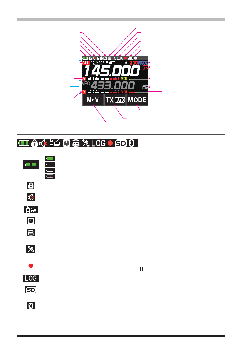
Touch Screen Display
Lights when DTMF function is enabled
Touch and hold: Moving Memory Data to the VFO register
Lights when Auto Power Off is active
Lights when AF DUAL Function is enabled
Lights when the mute Function is active
Displays mode
A-band display area
B-band display area
LOCK
Battery condition
A-band icon
B-band icon
Status Bar
The battery condition is displayed in 8 steps.
: Full battery power
: Battery is depleted. Charge battery.
(When blinking) Charge battery immediately.
:
Charging (displayed when the power is ON).
:
Appears when the lock function is enabled.
Appears when the Mute function for B-band is enabled.
Lights when GPS is acquired
Lights when GPS Log Function is enabled
Lights when the Voice memory function is enabled
Lights when a microSD memory card is inserted
Lights when Bluetooth function is active
Display of settings such as DG-ID/TONE
Communication Mode
Squelch/Volume Bar Graph (A-band)
Displays operation mode
Squelch/Volume Bar Graph (B-band)
Communication mode selection (AMS/DN/VW/FM)
Communication mode selection at AMS (TX AUTO/TX FM/TX DN)
Appears when the AF DUAL function is enabled.
Appears when the APO (Automatic Power-Off) function is enabled.
Appears when the DTMF Autodialer function is activated.
Appears when the Built-in GPS function is activated.
Appears: Satellites are acquired.
Blinks: Satellites cannot be acquired.
Appears when the Voice recording function is activated (About 3 seconds after the
squelch closes, the recording pauses and a “ ” appears.).
Appears when the GPS Log function is enabled.
Appears when a microSD card is inserted.
Appears when the Bluetooth® function is activated.
Appears: Bluetooth® device is connected.
Blinks: Bluetooth® device not connected.
6
Page 9

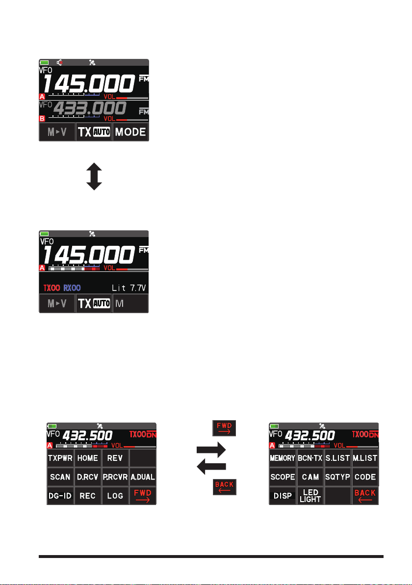
A-band / B-band display area
A-band / B-band display modes
: VFO mode
: PMG mode (Recalls only the frequencies registered in PMG)
: Memory mode (The numeric is the memory channel number)
Press the BAND key while in memory mode, the MAG function can automatically recall memory channels in groups for each of the following bands: (For
details, refer to “Using the Memory” on page 30.)
/ / / / / / /
: Home Channel
VDR : VFO Dual Receive (VFO ↔ Priority Memory Channel)
MDR :
Memory Channel Dual Receive (Memory Channel
HDR : HOME Channel Dual Receive (HOME Channel ↔ Priority Memory Channel)
: Repeater minus (-) shift
: Repeater plus (+) shift
: Split operation
Specified Memory Channel (Specify that only designated memory channels are
scanned during memory scanning.)
Skip Memory Channel (Permits designating unwanted channels to be skipped during
scanning.)
Priority Memory Channel (The transceiver checks for signals on the frequency registered to the selected Priority Memory Channel, once every 5 seconds.)
ATT (attenuator) function (When the desired signal is extremely strong, activate the
attenuator to reduce the incoming signal from the antenna.)
↔
Priority Memory Channel)
Bell function is activated.
TX/RX DG-ID is displayed
TXnn (The transmit DG-ID number), RXnn (The receive DG-ID number)
Squelch type is displayed (For additional details, refer to the Advanced Manual.)
: Tone Encoder (tone frequency is displayed)
: Tone Squelch (tone frequency is displayed)
: DCS (Digital Code Squelch) (DCS code is displayed)
: Reverse Tone (tone frequency is displayed)
: Signal Squelch
: Pager (EPCS)
The following can be set when the squelch expansion (see page 64) is on.
: Send the DCS code only during transmission.
: Send the CTCSS tone signal during transmit, and wait for the DCS code in
receive mode. (tone frequency is displayed)
: Send the DCS code during transmit, and wait for the CTCSS tone signal in
receive mode. (tone frequency is displayed)
7
Page 10
Displays the operating mode (Digital mode is indicated by a red icon)
: FM (Analog) mode
: Normal digital mode (digital mode using C4FM modulation)
: Wide digital mode (digital mode using C4FM modulation)
: Data FR mode (data communication mode using C4FM modulation)
: AMS (Automatic Mode Select) FM (Analog) mode
: AMS (Automatic Mode Select) DN mode
: AMS (Automatic Mode Select) VW mode
: AMS (Automatic Mode Select) DW mode
When AMS (Automatic Mode Select) function is activated, indicator is shown with a
bar appearing above the mode. The transceiver automatically switches to the DW
mode during image transmission.
: A-band icon
: B-band icon
: S meter (Displays received signal strength in 10 levels)
: Volume level
: SQL level
Touch keys display area
MODEMODE
Touch and hold: Moving Memory Data to the VFO register.
Each touch steps the transmit communication mode as follows:
TX (AUTO):
TX (FM):
TX (DN):
Each touch steps the communication mode as follows:
The current communication mode is displayed on the upper right of the frequency.
MODEMODE
*1 The AMS (Automatic Mode Select) function displays one of the
the automatically selected communication mode.
*2 When the Setup Menu item [TX/RX] [2 DIGITAL] [4 DIGITAL VW] is set to “ON”
(factory default is “OFF”), the Voice FR (VW) may be selected.
Automatically selects the transmit mode to correspond to the received signal.
Always transmits in the analog FM mode.
Always transmits in the digital (DN) mode.
/ / )
(
/ /
AMS function operation (A bar is displayed at the top of the communication
mode icon, and the AMS function automatically displays the selected communication mode.)
: V/D Mode (Voice/Data simultaneous transmission mode)
2
*
Wide digital mode (high-quality digital communication)
:
FM (Analog) mode
:
: PO meter (Displays transmit output in 4 levels when transmitting)
TX (AUTO)
1
*
:
1
*
TX (FM)
TX (DN)
*
2
( / / )
TX (AUTO)
• • •
1
*
/ / icons for
• • •
8
Page 11
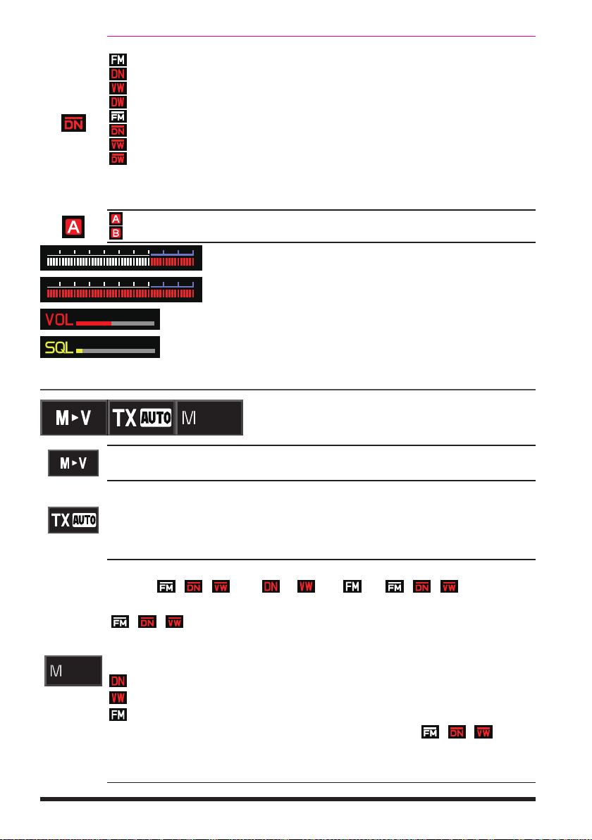
●Dual Band Screen
MODEMODE
A-band and B-band are displayed in a top-down fashion.
Both bands are received simultaneously.
Touch and hold the frequency of the operation band
(white display) to display the numeric keypad screen for
frequency input.
Touch the sub-band (gray display) frequency to change
the operation band.
When both the operation band and the sub-band are re-
ceiving signals at the same time, the audio on the subband receiver is automatically muted. Setup Menu: [TX/
RX] [3 AUDIO] [2 MUTE]: Allows setting the
muting level.
Press and hold the [A/B] key.
●Mono Band Screen
A-band or B-band is displayed.
Receives only the displayed band.
Touch and hold the frequency to display the numeric
keypad screen for frequency input.
The memory tag and battery voltage etc. are displayed
on the lower segment.
●Function Menu Screen (Press the [F ] key)
Press the [F ] key to displays the function menu screen.
Press the [BACK] key to return to the previous screen.
There are two function menus. Touch [FWD ] or [BACK
display to switch the screens.
Depending on the communication mode and settings, some functions may not operate
when the Menu item is touched.
Function Menu Screen 1
Touch
Touch
] at the bottom right of the
Function Menu Screen 2
9
Page 12

●PGM (Primary Memory Group Activity Monitor) Screen (Press the [PMG] key)
YAESU
YAESU
Up to 5 frequencies registered in PMG are displayed, and the signal strength received
by each channel is displayed as a bar graph.
Touch the bar graph to instantly switch the receiver to
that frequency.
Information on the selected channel is displayed at the
top of the screen, and you can transmit immediately by
pressing PTT.
●CAM (Channel Activity Monitor) Screen (Press the [F] key
Frequencies that are often used with friends can be registered to the CAM group memory channels, and then displayed on the CAM screen. The signal status and strength of
each channel in the selected group are shown in a bar graph.
Touch the bar graph to instantly switch the receiver to
that frequency.
CAM Group: Up to 10 groups, with up to 5 memory
chan- nels each, can be registered in each group.
●Band Scope Screen (Press the [F ] key
In VFO mode, the Band Scope searches the channels above and below the center receive frequency at high speed. The signal strengths are displayed on a graph, so the
presence or absence of a signal on any channel is easily noted.
The frequency may be changed by turning the DIAL
knob.
Touch [SEARCH] or [STOP] to begin or stop the search.
The number of channels to search in Band Scope may
be set to 19, 39 or 79. (See “Change the number of
channels displayed” page 42).
To end the Band Scope function, press the [BACK] key.
●GM (Group Monitor) Screen (Press the [GM/X] key)
Automatically listens for stations operating with GM function on the same frequency,
that are within the communication range, and displays the call sign, direction, distance,
within / outside. For details, refer to the separate GM Instruction Manual which is available on the Yaesu website.
The call signs of the stations that can communicate is
displayed in white characters.
The call signs of stations outside the sphere of commu-
nications are displayed in gray characters.
Touch [APL], to display the positions of multiple mem-
ber stations on the compass screen, centered on your
own station.
Touch [LOG] to view previously sent or received mes-
sages and photos.
To end the GM function, press the [GM] key.
Touch [SCOPE])
Touch [CAM])
10
Page 13
●AF DUAL Screen (Press the [F] key Touch [A.DUAL])
JA1YOE-123
While receiving and listening to a radio broadcast, the A-band and B-band may also be
monitored simultaneously for activity.
When a signal is received on A-band or B-band, the
broadcast audio is muted and the A or B band audio is
heard.
To end the AF DUAL function, press the [BACK] key.
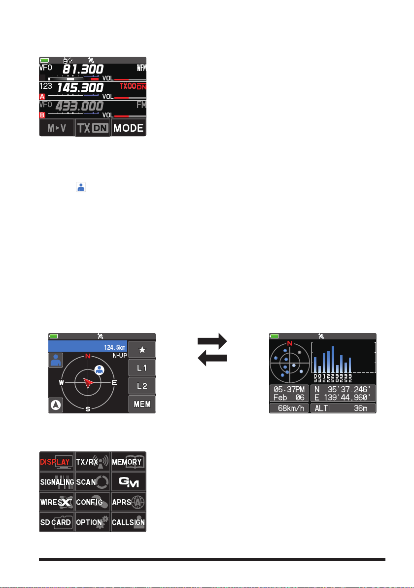
●BACKTRACK Screen (Press the [F ] key
Touch [DISP])
The backtrack screen, or the GPS information screen, whichever was displayed last, will
be displayed.
Real-time navigation function
Touch [
] at the top left of the screen to display the position and direction of the partner station in real time during communication in C4FM digital V/D mode. (The signal
of the partner station must contain location information.)
BACKTRACK function
May register the departure point etc. up to 3 places (“H”, “L1”, “L2”) in advance and
display the distance from the current location to the registered point in real time.
●GPS Information Screen (Press the [F ] key
Touch [DISP])
The backtrack screen, or the GPS information screen, whichever was displayed last, will
be displayed. The GPS satellites status and numbers are shown.
The following information is displayed.
Direction and elevation of satellites, and their signal strengths
Current time and date
Moving Speed
Backtrack Screen
●
Current latitude and longitude
●
Altitude of current location
GPS Information Screen
Touch the screen (other
than the Touch keys).
●SETUP MENU Screen (Press and hold the [F] key)
Setup Menu allows selecting various functions from the displayed list and setting the
parameters of each function according individual preferences.
Press the PTT switch or press the [BACK] key several
times to exit the Setup Menu.
11
Page 14
Safety Precautions (Be Sure to Read
)
Be sure to read these important precautions, and use this product safely.
Yaesu is not liable for any failures or problems caused by the use or misuse of this product by the purchaser or any third party. Also, Yaesu is not liable for damages caused
through the use of this product by the purchaser or any third party, except in cases
where ordered to pay damages under the laws.
Types and meanings of the marks
DANGER
WARNING
CAUTION
This mark indicates an eminently hazardous situation, which, if not avoided,
could result in death or serious injury.
This mark indicates a potentially hazardous situation, which, if not avoided,
could result in death or serious injury.
This mark indicates a potentially hazardous situation, which, if not avoided,
may result in minor or moderate injury or only property damage.
Types and meanings of symbols
These symbols signify prohibited actions, which must not be done to use this product safely.
For example: indicates that the product should not be disassembled.
These symbols signify required actions, which must be done to use this product safely.
For example:
indicates that the power plug should be disconnected.
DANGER
Do not use this product in an area where RF
transmitters are prohibited, e.g., inside of a
hospital, airplane, or train.
This product can affect electronic or medical devices.
Do not transmit with this device while carrying or using a medical appliance such as a
cardiac pacemaker. When transmitting, use
an external antenna and keep as far as possible away from the external antenna.
The radio wave emitted by the transmitter can
cause the medical device to malfunction and
result in injury or death.
Do not transmit with this device in a crowded
place for the safety of persons using a medical device such as a cardiac pacemaker.
The radio wave emitted from this product can
cause the medical device to malfunction and
result in injury or death.
Do not use this product or the battery charger anywhere inflammable gas is produced.
A fire or explosion can occur.
If thunder and lightening develop nearby
when an external antenna is used, immediate
ly turn this transceiver OFF, and disconnect
the external antenna from it.
A fire, electrical shock, or damage may result.
Do not use this product while riding a bicycle
or driving a car. Accidents can result.
Be sure to stop the bicycle or car at a safe place
before using this product.
Do not touch any material leaking from the
LCD display or the battery pack with bare
hands.
The chemical may adhere to your skin or enter
your eye, and cause chemical burns. In such a
case, consult the doctor immediately.
Do not solder or short-circuit the terminals
of the battery pack.
A fire, leak, overheating, explosion, or ignition
may result.
Do not carry the battery pack together with a
necklace, hairpin, or small metal objects. A short
circuit can result.
-
Do not disassemble or make any alteration
to this product.
An injury, electric shock, or failure may result.
Do not handle the battery pack or charger
with wet hands. Do not insert or remove the
power plug with wet hands.
An injury, leak, fire, or failure may result.
12
WARNING
Do not power this transceiver with a voltage
other than the specified power supply voltage.
A fire, electric shock, or damage may result.
Keep the terminals of the battery pack clean.
If terminal contacts are dirty or corroded, a fire,
leak, overheating, explosion, or ignition can result.
Page 15

If smoke or a strange odor is emitted from
the main body, battery pack, or battery charger, immediately turn the transceiver off;
remove the battery pack, and remove the
power plug from the outlet.
A fire, chemical leak, overheating, component
damage, ignition, or failure may result. Contact
the dealer from which you purchased this product
or Yaesu.
Do not bend, twist, pull, heat or modify the
power cord and connection cables in an unreasonable manner.
This may cut or damage the cables and result in
fire, electric shock and equipment failure.
Do not pull the cable when plugging and
unplugging the power cord and connection
cables.
Always hold the plug or connector when unplugging; if not, a fire, electric shock and equipment
failure may result.
Do not use the device when the power cord
and connection cables are damaged, or when
the DC power connector cannot be plugged
in tightly.
Contact Yaesu or the retail store where this
transceiver was purchased for assistance, as
this may result in fire, electric shock and equipment failure.
Do not install the transceiver or the wire cables near the automobile air bags.
In case of an accident, the transceiver may
interfere with air bag deployment and result in
extreme injury. The wire cables may also cause
the air bag to malfunction.
Do not make very long transmissions.
The main body of the transceiver may overheat,
resulting in component failure or operator burns.
Do not place the transceiver in wet or damp
areas (e.g. near a humidifier).
This may result in fire, electric shock and equipment failure.
Do not use DC power cords other than the
one enclosed or specified.
This may result in fire, electric shock and equipment malfunctions.
When connecting a DC power cord, be certain the positive and negative polarities are
correct.
Reverse connection will result in equipment
damage.
When transmitting, keep the transceiver at
least 5.0 mm (3/16 inch) away from your body.
Use only the supplied antenna. Do not use
modified or damaged antennas.
Disconnect the power cord and connection
cables before installing separately sold accessory items.
This may result in fire, electric shock and equipment failure.
Follow the instructions provided when installing items sold separately.
This may result in fire, electric shock and equipment failure.
Use only the provided or specified screws.
Using screws of a different size, may result in
fire, electric shock and component damage.
Do not place the transceiver in a confined
space, such as a bookshelf which is not ventilated well.
This may result in overheating and fire, electric
shock and equipment failure.
Do not operate the transceiver on a carpet or
a blanket.
This may result in overheating and fire, electric
shock and equipment failure.
If a foreign substance is spilled into the
transceiver, turn it OFF immediately and remove the power plug from the outlet.
If used as it is, a fire, electrical shock, or damage may result.
CAUTION
Do not place the transceiver on an unsteady
or sloping surface, or in a location with extreme vibration.
The transceiver may fall or drop, resulting in fire,
injury and equipment damage.
Do not place this transceiver in a humid or
dusty place.
A fire or failure may result.
Do not use the transceiver near the radio relay equipment.
Transmissions may affect radio communication.
Do not wipe the case using thinner and benzene etc.
Use only a soft, dry cloth to wipe stains from the
case.
Do not throw the transceiver, or subject it to
strong impact forces.
Physical abuse may result in component damage and equipment failure.
If the transceiver will not be used for an extended period, turn it OFF and remove the battery
pack for safety.
Keep magnetic cards and videotapes away
from the transceiver.
The data recorded on cash cards or videotapes
may be erased.
Do not place this transceiver in direct sunlight or near a heater.
The case may be deformed or discolored.
Do not operate the transceiver near the TV or
radio.
Radio disturbance can occur in the transceiver,
the TV, or the radio.
13
Page 16

Be sure to check with the manufacturer of
any hybrid or fuel-saving automobile regard
ing use of the transceiver in that car.
Noise generated by an onboard electrical device
(
inverter, etc.) can disrupt the normal operation
of the transceiver.
Do not transmit near the television and radio.
Transmissions may cause electromagnetic interference.
While transmitting, keep the antenna as far
from you as possible.
Long-time exposure to electromagnetic waves
may have a negative impact on your health.
Do not dangle or throw the transceiver by
holding its antenna.
This may injure others and may also result in
damage and failure of the transceiver.
Do not use the transceiver in a crowded
place.
The antenna may strike others and result in an
injury.
Keep this product out of the reach of children.
Injury to the child, or damage to the transceiver
may result.
-
Do not use any products other than the specified options and accessories.
Failure or miss operation may result.
Install the hand strap and belt clip securely.
Improper installation may cause the FT5DR/
FT5DE to fall or drop, resulting in an injury or
damage.
This product has a waterproof structure and
conforms to “IPX7” when the included antenna and battery pack are installed and rubber
caps are securely attached to the MIC/SP
jack, EXT DC IN jack, and DATA terminal. If
this transceiver gets wet, dry it with a soft
cloth, do not leave it exposed to the moisture.
Exposure to excessive moisture may degrade
the transceiver performance, shorten its life, or
cause a failure or electrical shock.
Before discarding a depleted battery pack, affix
tape or insulating covering to its terminals.
Do not use at extremely low atmospheric pressure.
About Waterproofing Feature Conforming to IPX7
When the included antenna and battery pack are installed and the MIC/SP jack, EXT
DC IN jack, DATA terminal, and microSD slot are securely covered with rubber caps,
this product is moisture and splash resistant. To ensure continued waterproofing protection, be sure to check the following points before use.
Check for damages, deterioration, and dirt.
m
Antenna rubber, key switch rubber, MIC/SP jack, EXT DC IN jack, DATA terminal, microSD
slot rubber cap, and battery pack joint.
Cleaning
m
When this product is contaminated with seawater, sand, or dirt, rinse with fresh water, and
then wipe with a dry cloth immediately.
Recommended maintenance interval
m
To ensure continued water resistance and optimal performance, it is recommended that
maintenance be performed annually, or when any damage or deterioration is found. Note that
the maintenance service is subject to fees.
Do not immerse this product in the following liquids:
m
Sea, pool, hot spring, water containing soap, detergent, or bath additive, alcohol, or chemicals.
Do not leave this product for an extended time in the following places:
m
Bathroom, kitchen, or humid place
Other precautions
m
Since this product is not totally waterproof, it cannot be immersed in water.
14
Page 17

Supplied Accessories and Options
Supplied Accessories
• Rechargeable Li-Ion Battery Pack (7.2V, 2,200mAh) SBR-14LI
• Battery Charger SAD-25
• Antenna
• Belt Clip
• Quick Release Holster SHB-26BK
• USB Cable
• Operating Manual (This Manual)
• SBR-14LI Manual
• Battery Pack protective cap
If any item is missing, contact the dealer from which you purchased the transceiver.
Available Options
• Speaker Microphone with Snapshot camera MH-85A11U
• Speaker / Microphone SSM-17A
• Earpiece Microphone SSM-57A
• VOX Headset SSM-63A
• Bluetooth® Headset SSM-BT10
• Microphone Adapter CT-44
• DC Cable with and Cigarette-Lighter Plug SDD-13
• DC Cable E-DC-6
• Quick Release Holster SHB-26BK
• Soft Case SHC-40
• 3x “AA” Cell Battery Case FBA-39
• Li-Ion Battery Packs (7.2V, 2,200mAh) SBR-14LI
• Li-Ion Battery Packs (7.4V, 1,100mAh) FNB-101LI
• Battery Charger SAD-25
• Rapid Charger CD-41
• PC connection cable SCU-39
• Cloning Cable CT-168
• PC connection cable CT-169
• Data Cable CT-170
• Data cable (2.5) CT-176
• Belt Clip SHB-13
• BNC-to-SMA Adapter (BNCJ-SMAP) CN-3
15
Page 18

Preparation
Hold the thick base
Battery Latches
Supplied screws (black)
for the Quick release Holster
Supplied screws (silver)
for the Belt Clip
To remove the holster,
press the release knob.
②
Press holster firmly
①
slots on the bottom of the FT5DR/DE
Installing the Antenna
Turn the antenna clockwise until it is secured.
• Do not hold or twist the upper part of the antenna
when installing or removing it. To do so may break the
conductors inside the antenna.
• Do not key the transmit without installing the antenna. The
transmitter components may be damaged.
Installing the Battery Pack
1. Insert the bottom tabs of the battery pack in the slots on
the back side lower part of the transceiver.
2. Push the battery in until the battery latches click securely.
Charge the battery pack before using the transceiver for the
first time after purchase, or when it has not been used for a
long period time.
Risk of explosion if battery is replaced by an incorrect type.
Dispose of used batteries according to the instructions
●Removing the Battery Pack
While pressing down the latches, remove the battery pack.
Attaching the Quick Release Holster
Attach the quick release holster using the supplied screws (two).
until you hear the
latch click.
of the antenna
Attaching the Belt Clip
Attach the belt clip using the supplied screws (two).
Be sure to use the supplied screws when attaching the belt clip. If any other screws are used, the
belt clip cannot be secured firmly to the battery pack and the transceiver may drop off together
with the battery pack; the transceiver and battery pack may fall off, breakage and other damage.
16
Insert the bottom tabs of the Quick Release Holster in the
Page 19

Charging the Battery Pack
EXT DC IN jack
Charging the Battery Pack using the Battery Charger (SAD-25)
Using the supplied battery charger (SAD-25), it takes about 9 hours* to charge the SBR14LI battery pack fully.
*Depending on the battery status, the charging time might be increased
1. Referring to the figure at the right, connect the
battery charger plugs.
When the battery is being charged, the TX/BUSY
Indicator of the A-band lights red, and “Now
Charging” is displayed. The charge level is indicated by a bar graph.
2. When charging is completed, the display will
change to indicate “CHGFUL” and the TX/BUSY
Indicator will light green.
While the transceiver power is ON, “
” will ap-
pear on the display.
In the USA Version, the TX/BUSY LED is not lit when charging or when charging is complete.
When the charge is complete, the transceiver turns OFF after 3 minutes.
• If “CHGERR” appears on the LCD during the charging and the battery pack is not charged
after a lapse of 10 or more hours, stop charging the battery pack immediately. The battery
pack is presumed to be at the end of its service life, or defective. In this case, replace the
battery pack with a new one.
• Charge the battery pack within the temperature range from +41°F to +95°F (+5°C to
+35°C).
Charging the Battery Pack using the Rapid Charger (CD-41)
The optional Rapid Charger (CD-41) requires about 5 hours to charge the SBR-14LI
battery pack.
1. Insert the DC plug from the SAD-25 into the DC jack on the CD-41 rear panel, then
plug the SAD-25 into the AC line outlet.
2. Place the transceiver with battery pack attached or the battery pack alone into the
CD-41, charging will start and the red LED (CHARGING) of the CD-41 will light up.
3. When charging is complete, the red “CHARGING” indicator turns OFF and then the
green “FULL” indicator will light.
It may take some time for the green LED to turn ON after the red LED turns OFF.
●Approximate Operating Time and Remaining Charge Level Indication
Approximate operating time for the transceiver with the fully charged battery pack or
new AA alkaline batteries is as follows:
Band in Use
Digital: OFF
Amateur Band
144 MHz Band Approx. 9.5 hours Approx. 4.5 hours Approx. 12 hours
430 MHz Band Approx. 8 hours Approx. 4 hours Approx. 11 hours
The battery charge level calculations are based on an operating cycle of: Transmitting
6 seconds (5 W): Receiving 6 seconds (VOL Level 16): Stand By 48 seconds (RX SAVE
1:5)
The actual times the transceiver will operate as indicated in the above table, varies depending on use, conditions, ambient temperature, etc.
Battery pack
SBR-14LI
Battery pack
FNB-101LI
Battery charger
SAD-25 (supplied)
Battery
FBA-39
17
Page 20

External Power Supply
Contact surface
Connecting an External Power Supply for Use in a Vehicle
The optional DC Cable with Cigarette-Lighter plug (SDD-13) allows power to be supplied
from a motor vehicle type cigarette lighter socket.
Connecting to an External Power Supply Using a Power Cable
The optional DC cable (E-DC-6) allows the transceiver to be connected to an external
DC power supply.
Using a microSD Memory Card
Using a microSD memory card with the transceiver allows the following functions.
Backing up the transceiver data and information
Saving memory information
Voice recording/playback
Saving GPS log data
Saving image data captured with the optional camera-equipped microphone (MH-
85A11U)
Saving messages downloaded with the GM function or WIRES-X function
Usable microSD Memory Cards
This transceiver only supports the following capacity of microSD and microSDHD memory cards.
・
2GB
4GB
・
• microSD memory cards formatted on other devices may not properly save information
when used with this transceiver. Format microSD memory cards again with this transceiver
when reusing memory cards formatted with another device.
• Do not remove the microSD memory card or turn the transceiver OFF, while saving data to
a microSD memory card is in progress.
・
8GB
16GB ・ 32GB
・
Mounting and Dismounting microSD Memory Card
1. Press and hold the Power (Lock) switch to turn
the transceiver OFF.
2. Insert the microSD memory card into the card
slot until a clicking sound is heard (as shown in
the figure at the right).
3. Press and hold the Power (Lock) switch to turn
the transceiver ON.
When the memory card is properly detected,
” lights on the display.
“
●Removing the microSD memory card
To remove the microSD memory card (inserted in step 2 above), push the memory card
in until a clicking sound is heard, then remove the memory card.
18
Page 21

Formatting a microSD Memory Card
Format a new microSD memory card following the steps below before use.
• Formatting a microSD memory card erases all data saved on it. If you are going to format
the microSD memory card you are using, be sure to check the data saved on it before
formatting.
• The microSD memory cards used in other devices may not be recognized by the FT5DR/
DE, or it may take an abnormally long time to read or write. So normally, they may not
be useable. Reading and writing of the microSD cards may be improved by using the SD
memory card formatter provided by the SD Association. The SD memory card formatter
can be downloaded from this URL (https://www.sdcard.org/downloads/formatter/).
1. Press and hold the [F ] key.
The “SETUP MENU” screen appears.
2. Touch [SD CARD].
3. Touch [4 FORMAT].
“FORMAT?” appears on the LCD.
4. Touch [OK] twice.
Initialization starts and “Waiting” appears.
To cancel formatting, select [CANCEL].
•
5. When formatting is completed, a beep sounds and “COMPLETED” appears on the
LCD.
19
Page 22

Operation
Turning the Transceiver ON
Press and hold the Power (Lock) switch to turn the transceiver ON.
●Turning the transceiver OFF
Press and hold the Power (Lock) switch again to turn
the transceiver OFF.
●Inputting the call sign
The first time the transceiver is turned ON after it is
purchased; input your own call sign.
1. Press the [F ] key to proceed to the call sign in-
put screen.
When the transceiver is turned ON the second time,
•
and subsequently, the opening screen appears
followed by the frequency screen.
Input call sign may be changed from Setup Menu
•
[CALLSIGN] (page 68).
2. Input the call sign (toggle the alphabet input screen,
and the number input screen when necessary).
3. Save the entered call sign:
4. Press the PTT switch or press and hold the [F ]
key.
• Up to 10 characters (letters, numbers, and symbols)
can be entered.
• Characters that may be inputted for the call sign are
the numbers 0-9, letters A-Z (upper case), the hyphen
and the slash.
Please enter your
Callsign.
(Max 10 letters)
Adjusting the Volume Level
1. Rotate the VOL knob to adjust the volume to a comfortable level.
The transceiver volume levels for the A-band and
•
B-band are adjusted separately.
The transceiver volume levels for the AM broad-
•
cast band and the FM broadcast band are adjusted
separately.
The fidelity (audio pitch) of the received audio in C4FM digital mode can be
emphasized in the high range or the low range. Use Set Mode [TX/RX] [DIGITAL]
[5 AUDIO PITCH] (see page 63)
20
Page 23

Adjusting the squelch setting
The squelch level may be adjusted to mute the background noise when no signal is
present.
1. Press the SQL key and then rotate the VOL knob to adjust to a level at which the
background noise is muted.
appears on the display.
The transceiver squelch levels for the A-band and B-band are adjusted separately.
•
The transceiver squelch levels for the AM broadcast band and the FM broadcast
•
band are adjusted separately
2. After the adjustment, press the SQL key again, or wait for about 3 seconds to save
the setting.
• The default setting is “1” (setting “2” is for FM broadcast band).
• When the squelch level is increased, the noise is more likely to be silenced, but it may
become more difficult to receive weak signals.
Toggling the Operating Band
Normally, both operating bands are displayed on the top
half and bottom half of the transceiver touch screen. This
is Dual band.
With one of the bands selected, change the frequency and
radio operating mode.
The selected band (displayed in white letters) is called
•
Operating band.
The other band (displayed in gray letters) is called Sub-
•
band.
Each time pressing the [A/B] key toggles the operating
•
band.
The desired operating band may also be selected by
•
touching the frequency display.
In dual receive mode, when receiving a signal in the
operation band, the received audio in the sub-band is
automatically muted. For additional details, refer to the
Advanced Manual which may be downloaded from the
Yaesu website.
●Switching the Mono-band Screen
Pressing and holding the [A/B] key will switch between
Mono-Band and Dual-Band displays. In Mono-Band mode,
only the operating band is shown.
Each time pressing the [A/B] key toggles the operating
•
band.
MODEMODE
To change the font color of the frequency display on the operation band to Blue or Red, use
Set Mode: [DISPLAY] [7 DISPLAY COLOR] (see page 63)
21
Page 24

Selecting a Frequency Band
470MHz~770MHz
137MHz~174MHz 174MHz~222MHz 222MHz~ 420MHz 420MHz~ 470MHz 770MHz~999.995MHz
470MHz~579.995MHz
108MHz~137MHz
137MHz~174MHz 174MHz~222MHz 222MHz~420MHz 420MHz~ 470MHz
Press the [BAND] key to select the desired frequency
band.
1. Press the [F ] key to display the function menu
screen.
2. Press the [BAND] key to switch the frequency bands
in reverse order.
3. Press the [BACK] key to return to the previous
screen.
Unwanted frequency bands can be set in the setup menu so they are not displayed in the
A-band or the B-band. Use Set Mode [CONFIG] [22 BAND SELECT] (see page 66).
The frequency bands that can be selected for each of the A and B bands are as follows:
●Frequency bands on A-band
AM BC Band
520kHz~1710kHz 76 (88*)MHz~ 108MHz
144 MHz Band
VHF (1) VHF (2)
SW Band
1.8MHz~30MHz 30MHz~76 (88*)MHz 108MHz~137MHz
50 MHz BandFM BC Band AIR Band
430 MHz Band
* Europe version
UHF (1) UHF (2)
●Frequency bands on B-band
AIR Band
144 MHz Band
VHF (1)
VHF (2) UHF (1)
430 MHz Band
Tuning to a Frequency
●DIAL knob
1. Press the [F ] key to display the function menu
screen.
2. Rotating the DIAL knob, the frequency will change in
1 MHz steps.
3. Press the [BACK] key to return to the previous
screen.
●The numeric keys
1. Touch and hold the frequency displayed on the LCD.
The numeric keypad appears.
2. Enter the frequency using the numeric keys.
145.000
Example: To input 145.520 MHz
[1]
[4]
[5]
[5]
[2]
Example: To input 430.000 MHz
[
ENT
]
[3]
[4]
When entering a frequency using the numeric keys, it
may be canceled by pressing the PTT switch or any key.
22
Page 25

Changing the Frequency Step
The DIAL knob rotation frequency step may be changed. Normally, the factory default
setting will provide a good frequency step.
1. Press and hold the [F ] key, then touch [CONFIG].
2. Touch [18 STEP] then rotate the DIAL knob to change the frequency step.
3. Press the PTT switch to save the setting and return to normal operation.
• In the default setting, of the frequency step is set to “AUTO”, which automatically provides
a suitable frequency step according to the frequency band.
• The frequency steps that can be set differ depending on the frequency band.
Selecting the Communication Mode
●Using AMS
The FT5DR/DE transceiver is equipped with the AMS
(Automatic Mode Select) function which automatically
selects the communication mode corresponding to the
received signal.
To utilize the AMS function, touch [MODE] repeatedly
to display “
receiving the signal, “FM” of “
the mode of the received signal.
*The display differs depending on the received signal.
The bar at the top of the mode display indicates that the AMS feature is on.
●Setting the transmit mode when using the AMS function
The AMS function will automatically set the receiver to
the mode of the received signal, but the transmission
mode may be fixed regardless of the received mode.
1. Touch [TX AUTO]* to tune to the desired transmit
mode as follows.
*The display differs depending on the transmit mode.
”*, “ ”* or “ ”* on the display. After
” will change to indicate
Transmit Mode
(default)
(TX DIGITAL)
Receive and Transmit
Receive׃ Automatically selects the communication mode of transmis-
sion according to the signal being received.
Transmit: Transmits automatically in the communication mode selected
by the AMS function.
Receive׃ Automatically selects the communication mode of transmis-
sion according to the signal being received.
Transmit: Always transmits in the analog FM mode.
Receive׃ Automatically selects the communication mode of transmis-
sion according to the signal being received.
Transmit׃ Always transmits in the DN mode.
23
Page 26

Fixing the Communication Mode
TX/BUSY LED
To fix the transmission mode for operation, touch [MODE]
to switch the communication mode.
Communication Mode Icon Description of Modes
Voice/Data simultaneous transmission mode)
(
(High speed data Communication Mode)
1 When the Setup Menu [TX/RX] [2 DIGITAL] [4 DIGITAL VW] is set to “ON”
*
V/D Mode
Voice FR Mode*
(Voice Full Rate Mode)
FM Mode
AM Mode (receive only)*
Data FR Mode
1
2
This is the standard digital mode.
Calls are less prone to interruptions caused by detection and correction of the received digital voice signal.
High speed data communication using entire 12.5 kHz
1
*
band.
Enables high-quality voice communication.
Analog communication using FM mode.
The AM mode for receive only.
High speed data communication mode using the entire
12.5 kHz bandwidth for data communication. Automatically switches to this mode during image transmission.
(factory default is “OFF”), the Voice FR mode (VW) may be selected.
*2 When the Setup Menu [TX/RX] [1 MODE] [3 RX MODE] is set to “AUTO”
(factory default setting), AM mode is automatically selected within the AIR band (108
- 136.995 MHz).
Transmission
1. While pressing and holding the PTT switch, speak
into the microphone.
The TX/BUSY indicator will glow red during transmis-
sion.
If the PTT switch is pressed when a frequency other than
the amateur ham radio band is selected, an alarm tone
(beep) will be emitted and “TX INHIBIT” appears on the
LCD, disabling transmission.
2. Release the PTT switch to return to receive mode.
When receiving a signal, the TX/BUSY Indicator
lights according to the receive mode.
Receive Band TX/BUSY LED
The TX / BUSY LED blinks while receiving a signal that does not match the DG-ID or
similar tones, and when the sub-band audio is muted with the sub-band mute feature.
C4FM receiving Blue
Analog FM receiving Green
If transmission is continued for a long period, the transceiver overheats and the high
temperature protection function is activated. As a result, the transmitting power level is
automatically set to Low Power. If transmission continues while the high temperature
protection function is active, the transceiver will be forcibly returned to the receive mode.
24
Page 27

Changing the Transmit Power Level
1. Press the [F ] key, then touch [TXPWR].
2. Rotate the DIAL knob to select one of the following
transmit power levels:
TX PO Level PO Meter
HIGH (5 W)*
LOW3 (2.5 W)
LOW2 (1 W)
LOW1 (0.1 W)
*The default setting. When the optional alkaline battery case (FBA-39) is used, only LOW2 (about
0.9W) and LOW1 (about 0.3W) can be selected.
3. Press the PTT switch to save the setting and return to the normal operation.
The transmit power level may be set separately for each frequency band.
Locking Keys and DIAL knob
1. Press the Power (Lock) switch, “LOCK” is displayed
on the display for one second, the “
on the LCD, and then the keys and DIAL knob are
locked.
” icon appears
• The keys, the DIAL knob, and the PTT switch may be selected to be locked using Setup
Menu [CONFIG] [9 LOCK]. The default setting is the “KEY&DIAL” (the keys and the
DIAL knob are locked).
• The [MONI/T-CALL] key, [SQL] key and the VOL knob cannot be locked.
2. Press the POWER (Lock) switch again, “UNLOCK” will be displayed on the Display
and keys and the DIAL knob are unlocked.
25
Page 28

Using the convenient Digital C4FM feature
About the Digital Group ID (DG-ID) feature
1. Digital Group ID (DG-ID) function allows communications with only the specific group
members using the two-digit ID numbers. The desired DG-ID number from 00 to 99
is set in advance by all the group members. This ID number may be set separately
for transmit and receive, when the same ID number is set for both transmit and receive, only group members with the same ID number will be heard. This feature may
be used to communicate only with group members that have the same DG-ID number. The GM function may also be utilized to automatically monitor whether or not
group member stations with the same DG-ID number are operating within communication range.
The DG-ID number 00 detects signals with all ID numbers. Normally setting the ID
number to “00” for both transmit and receive will permit reception of the signals from
all other stations using the digital C4FM mode, regardless of the transmit DG-ID
number settings of the other stations.
Also note that when the receive DG-ID number of your transceiver is set to a DG-ID
number other than “00”, received signals that do not have the same DG-ID number
may not be heard.
2. When accessing the C4FM digital repeater controlled by the DG-ID number, set the
transmit DG-ID number of the FT5DR/DE to that of the repeater input. Even in that
case, if the receive DG-ID number of the FT5DR/DE is set to “00”, all the downlink
signals from the repeater may be received.
Communicating with the DG-ID feature
• Digital C4FM mode transceivers compatible with the DG-ID function are required in order
to utilize this function.
• If the firmware is not compatible with the DG-ID function, update the latest firmware to use
the DG-ID function. The latest firmware is available on the YAESU website.
Setting the transmit and receive DG-ID number to “00” for communicating
with all other stations using C4FM digital mode
1. Press the [F ] key, and touch [DG-ID].
If [DG-ID] is not displayed, touch [BACK
[DG-ID] and then touch it.
2. The DG-ID number setting screen will be displayed.
If the transmit DG-ID (DG-ID TX) number is not set
to “00”, press the [F ] key then rotate the DIAL
knob to set “00”, and then press the [F ] key.
3. Rotate the DIAL knob to select the receive DG-ID
(DG-ID RX).
4. If the receive DG-ID number is not set “00”, press the
[F ] key then rotate the DIAL knob to set “00”,
and then press the [F ] key.
] to display
DG-ID TX : 00
DG-ID RX : 00
DG-ID TX : 00
DG-ID RX : 00
5. Press the [BACK] key or the PTT switch to save the setting and return to the normal
operation.
The setting is complete.
26
Page 29

6. To check whether or not other stations are operating within communications range,
press the [GM/X] key to turn the GM (Group Monitor) function ON.
The other stations also need to turn the GM (Group Monitor) function ON.
•
Refer to the separate Operating Manual GM Edition for details on how to use the
•
GM function (download the manual from our YAESU website).
7. Press the [GM/X] key to turn the GM (Group Monitor) function OFF and return to the
normal operation.
• While setting the DG-ID number, pressing and holding the [GM/X] key will set the transmit
and the receive DG-ID numbers to “00”.
• If the receive DG-ID is set to a number other than “00”, only signals with that DG-ID will be
received. Normally, set the receive DG-ID number to “00” except when communication is
desired only with group members.
• The transmit and receive DG-ID default number is set to “00”.
Communicating only with the specific members by setting the DG-ID number
except for “00”
Example: Set the DG-ID number of to “50”
1. Press the [F ] key, and touch [DG-ID].
If [DG-ID] is not displayed, touch [BACK
[DG-ID] and then touch it.
The DG-ID number setting screen will be displayed.
] to display
DG-ID TX : 00
DG-ID RX : 00
2. Press the [F ] key, then rotate the DIAL knob to
set the transmit DG-ID (DG-ID TX) to “50”.
DG-ID TX : 50
DG-ID RX : 00
3. Press the [F ] key again, then rotate the DIAL
knob to select the receive DG-ID (DG-ID RX).
DG-ID TX : 50
DG-ID RX : 00
4. Press the [F ] key, then rotate the DIAL knob to
set the receive DG-ID (DG-ID RX) to “50”.
DG-ID TX : 50
DG-ID RX : 50
27
Page 30

5. Press the [BACK] key or the PTT switch to save the setting and return to the normal
The group member set the DG-ID number to “50”
signals that do not match the DG-ID number.
Setting the receive DG-ID number to
operation.
6. Press the [GM/X] key to turn the GM (Group Monitor)
function ON and check whether or not other stations
that are operating on frequency, with the GM (Group
Monitor) function ON, and have the same GD-ID number setting, are in the communication range.
The other stations also need to turn the GM (Group
•
Monitor) function ON.
7. Press the [GM/X] key to turn the GM (Group Monitor) function OFF and return to the
normal operation.
• While setting the DG-ID number, pressing and holding the [GM/X] key will set the transmit
and the receive DG-ID numbers to “00”.
• If the receive DG-ID is set to a number other than “00”, only signals with that DG-ID will be
received. Normally, set the receive DG-ID number to “00” except when communication is
desired only with group members.
For example, if the transmit and receive DG-ID numbers of group members are all set to “50”,
communications from other DG-ID numbers is not received and only the group members
setting the same DG-ID numbers may communicate. Also, the other stations setting the
receive DG-ID to any number except for “00” may not receive the signals of your stations.
“00” , all the C4FM digital stations may
be received signals.
DG-ID
(transmit)
T50
(receive)
R50
Only group members set to the same DG-ID
number may communicate.
T50
R50
28
DG-ID
(transmit)
(receive)
The other stations setting the receive DG-ID number
to a number other than “00” may not receive the
DG-ID
(transmit)
T00
(receive)
R00
DG-ID
(transmit)
T90
(receive)
R90
T00
R00
DG-ID
(transmit)
(receive)
Page 31

Repeater Operation
Repeater Shift Icon
Communicating Via the Repeater
The transceiver includes an ARS (Automatic Repeater Shift) function which sets the repeater operation automatically when the receiver is tuned to the repeater frequency.
1. Set the downlink (output) frequency from the repeater.
2. “
” or “ ” and “TN” icons may automatically appear
above the frequency.
3. Speak into the microphone while pressing and holding
the PTT switch.
●The reverse state
The “reverse” state temporarily reverses the transmit and receive frequencies. This
allows checking to find if direct communication with the other station is possible.
1. Press the [F ] key, then touch [REV].
If [REV] is not displayed, touch [BACK
] to display
[REV] and then touch it.
The transmit and receive frequencies are temporar-
•
ily reversed (“reverse” state).
In the “reverse” state, the “
•
” or “ ” blinks on the
display.
2. Press the [F ] key, then touch [REV] to exit from
the “reverse” state.
• The ARS function may be set to OFF in the Setup Menu [CONFIG] [14 RPT ARS].
• The repeater settings may be changed from the Setup Menu.
Setup Menu [CONFIG] [15 RPT SHIFT]: Allows setting the repeater shift direction.
Setup Menu [CONFIG] [16 RPT SHIFT FREQ]: Allows changing the repeater shift
offset.
Setup Menu [SIGNALING] [12 TONE SQL FREQ]: Allows setting the tone encoder
frequency.
Tone Encoder Icon
●Tone Calling (1750 Hz)
If the transceiver is an FT5DE (European version), press and hold in the MONI/
T-CALL switch (just below the PTT switch) to generate a 1750 Hz burst tone to access
the European repeater. The transmitter will automatically be activated, and a 1750 Hz
audio tone will be superimposed on the carrier. Once access to the repeater has been
gained, you may release the switch, and use the switch for activating the transmitter
thereafter. If you need to access the repeaters which require a 1750 Hz burst tone
for access by the FT5DR (USA/Asian versions), you can set the switch to serve as a
“Tone Call” switch instead. To change the configuration of this switch, use Set Mode
[CONFIG] [10 MONI/T-CALL].
29
Page 32

Using the Memory
The FT5DR/DE transceiver incorporates a large number of memory channels that can
register the operating frequency, communication mode, and other operational information.
900 Memory Channels
99 Skip Search Memory Channels
11 Home Channels
50 pairs PMS Memory Channels
Preset Receiver Memory Channels include the International VHF marine radio (57
channels) and Worldwide Wide Broadcasts (89 channels)
With the memory auto grouping (MAG) function, memory channels only in the same
r
frequency band may be automatically recalled as a group.
The operating frequency and other operational information can be registered to each
regular memory channel, home channel, or PMS memory channel:
• Operating frequency • Operation Mode • Frequency Step • Transmitter output
• Memory tag • Repeater Shift • TX/RX DG-ID • Tone information
• DCS information • ATT • Specified Memory Channel
• FM mode bandwidth • S meter squelch • Memory channel skip information
Memory channels can be sorted and registered into memory banks according to the in-
tended use. The transceiver allows using 24 types of memory banks. A maximum of 100
memory channels can be registered in each memory bank.
Back up the stored contents to a microSD memory card. For details on saving a
backup onto a microSD memory card, refer to the Advanced Manual which may be
downloaded from the Yaesu website.
Note
Registering to Memory Channels
1. Set the frequency and the communication mode to be
registered to a memory channel.
2. Press and hold [V/M] key.
The memory channel number blinks.
The memory channel number next to the previously
recalled memory channel is automatically selected.
3. Rotate the DIAL knob to select the desired channel
number.
The channel number of a memory channel that has
•
already been written or deleted blinks in red.
Touch [
•
ward 10 channels at a time. Touch [
cancel fast-forward.
4. Press the [V/M].
If you attempt to register a frequency to a memo-
•
ry channel that already contains frequency data,
“OVERWRITE?” will appear on the LCD. Touch [OK]
twice to overwrite the memory channel.
The memory tag input screen will be displayed on the LCD.
•
5. Input the memory tag.
If not entering a name tag → proceed to step 6.
], and rotate the DIAL knob to fast-for-
] again, to
30
Page 33

Use the numeric keys to input the characters.
•
Touch
•
See “Text input screen” on page 70 to input a memory tag.
•
to move the cursor to right in the text input area.
6. Press the PTT or [V/M] key, to save the data to memory and return to normal oper-
ations.
Recalling a Memory Channel
1. Press the [V/M] key.
The memory channel most recently used appears on the display.
2. Rotate the DIAL knob to select the desired memory channel.
Press the [F ] key, and rotate the DIAL knob to fast-forward 10 channels at a
•
time. Press the [F ] again, to cancel fast-forward.
Touch and hold [
•
] to transfer the memory contents to the operating band
VFO.
3. Press the [V/M] key to exit the memory mode, and return to the VFO operation.
• When a tagged Memory channel is recalled, both memory tag and frequency will be
displayed. (Memory tag is displayed only on the operating band.)
• Touch the frequency display of the operating band to switch between memory tag display
and normal frequency display.
• On the B-band, the: “AM broadcast band”; “FM broadcast band”; “Shortwave broadcast
band”; “50 MHz band” and “UHF(2)” cannot be called.
Recall only memories in the same frequency band (Band) using the memory auto grouping (MAG) function
With the memory auto grouping (MAG) function, only memory channels in the same
frequency band (Band) can be called.
In the memory mode, each time the [BAND] key is pressed, only memory channels of
the specified frequency band are automatically recalled as a group, as shown below:
Group Name Selectable Memory Channels
ALL
AIR
144MHz
430MHz
AM
FM
SW
OTHER
All memory channels*.
AIR band memory channels only.
144 MHz band memory channels only.
430 MHz band memory channels only.
AM broadcast band* memory channels only.
FM broadcast band* memory channels only.
Shortwave broadcast band* memory channels only.
50 MHz band*, VHF(1), VHF(2), UHF(1) and UHF(2)* memory
channels only.
*On the B-band, the: “AM broadcast band”; “FM broadcast band”; “Shortwave broadcast
band”; “50 MHz band” and “UHF(2)” cannot be called.
The
icon is light, and the other icons blink when they are active.
31
Page 34

Clearing Memories
1. Press and hold the [V/M] key.
2. Rotate the DIAL knob to select the memory channel
from which the data is to be cleared.
3. Touch [
Confirmation screen “DELETE?” is displayed.
4. Touch [OK] twice to clear the memory channel.
Data on Memory Channel One, Priority Channel, and the Home Channel may not be cleared.
], then touch [M.DEL].
Restored erased memory
1. Press and hold the [V/M] key.
2. Rotate the DIAL knob to restore the channel.
3. Touch [
4. Touch [M.REV] to restored the memory channel.
].
Using Memory Tag
Memory name tags, such as a call sign or broadcast station name may be assigned to
the memory channels and home channels. Input a memory tag using up to 16 characters. Alphabetic characters (upper and lowercase), Numbers and Symbols may be entered to the memory name tag.
1. Press the [V/M] key to enter Memory mode.
2. Rotate the DIAL knob to Recall the memory channel to
assign the name.
To assign a name to a home channel, recall the de-
sired home channel.
3. Press and hold the [F ] key, and then touch
[MEMORY].
4. Touch [3 MEMORY NAME].
Use the numeric keys to input the characters.
•
Touch
•
input area.
See “Text input screen” on page 70 to input a
•
memory tag.
to move the cursor to the right in the text
• When a memory tagged Memory channel is recalled, both the memory tag and the
frequency will be displayed. (The Memory tag is only displayed on the operating band.)
• Touch the frequency display of the operating band to switch between memory tag display
and normal frequency display of all memory channels.
32
Page 35

Recalling the Home Channels
1. Press the [F ] key, and then touch [HOME].
If [HOME] is not displayed, touch [BACK
[HOME] and then touch it.
“HOM” and the home channel frequency of the cur-
•
rently selected band appears on the LCD.
Each time the [BAND] key is pressed, operation
•
switches to the home channel of another frequency
band.
2. Press the [V/M] key, or press the [F ] key, and
then touch [HOME] to return to the previous frequency.
• While recalling the home channel, rotate the DIAL knob to transfer the home channel
frequency to the VFO operating band.
• The home channel frequency can be set not to be transferred in the Setup Menu [CONFIG]
[8 HOME VFO] (page 65).
] to display
Changing the Home Channel Frequency
1. Set the frequency and the operating mode you want to store as a home channel.
2. Press and hold the [V/M] key.
3. Touch [
Confirmation screen “OVERWRITE?” is displayed.
4. Touch [OK] twice.
The memory tag input screen will be displayed on the LCD.
5. Input the memory tag.
If not entering a name tag proceed to step 6.
See “Text input screen” on page 70 to input a memory tag.
•
6. Press the [V/M] key, or press the PTT switch, to changed home channel frequency
and return to normal operations.
], and then touch [H.WRITE].
For additional details on the following functions, refer to the Advanced Manual which may be
downloaded from the Yaesu website.
Memory Channel List
All memory channels can be displayed and recalled from the list.
Split Memory
Two different frequencies, one for receive and another for transmit, can be registered to
a memory channel.
Using Memory Bank
The transceiver allows using up to 24 memory banks to allow sorting and registering the
channels in convenient groups.
Memory Only Mode
The transceiver may be placed into a Memory Channel Only mode, (which restricts the
FT5DR/DE to operate only on the memory channels).
33
Page 36

PMG (Primary Memory Group Activity Monitor)
Memory channel tag
frequencies outside the frequency
be displayed as a bar graph.
If an often-used frequency is registered with your friends in a PMG (Primary Memory
Group), it can be recalled that frequency immediately by
pressing the [PMG] key. The PMG function displays the
registered frequency signal status (received signal strength)
in a bar graph (activity monitor). You can instantly move to
that channel simply by touching the bar graph (TOUCH &
GO Operation).
The activity monitor can display up to 5 channels, but it is
very convenient to register about 2 or 3 frequently used frequencies.
Press briefly
Memory channel number
currently selected
Currently selected
channel
(displayed in orange)
PMG channel number
YAESU
Display in gray even if the
received signal is lost.
Switch to the frequency by
touching the bar graph.
Gray bar graph is displayed for
range (108 to 580 MHz) that can
Example: When 3 frequencies are registered
When frequencies other than 108MHz to 580MHz (i.e.: shortwave broadcasting; AM/FM
radio; 50MHz band; etc.) are registered to PMG, a gray bar graph is displayed. Touch the bar
graph to switch to the receive frequencies and hear the signals.
Register the frequency with PMG
You can register up to 5 current frequency channels to PMG by simply pressing and
holding the [PMG] key.
1. Set the frequency and the communication mode, or the
memory channel you want to register in PMG.
2. Press and hold the [PMG] key to register the current
channel to PMG and display the activity monitor screen.
3. To continue registering additional frequencies, press
the [PMG] key or [BACK] key to return to the original
screen, and then repeat steps 1 and 2 above.
If the memory channel is already registered, an error
•
alarm will sound, and the channel will not register to
PMG.
Up to 5 channels can be registered in PMG. If you want to register a new frequen-
•
cy, cancel one of the registered frequencies and then register a new frequency.
Press and Hold
When 1 frequency is registered When 3 frequencies are registered
34
YAESU YAESU
Page 37

Touch the bar graph to switch the frequency
1. Touch the bar graph on the screen.
The touched bar graph is displayed in orange and the
•
receive is set to that frequency.
The receive frequency may also be changed by turn
•
ing the DIAL knob.
YAESU
-
Unregister the channel (frequency) registered in PMG
1. Select the channel (frequency) to be unregistered by
touching the bar graph or turning the DIAL knob.
2. Press and hold the [PMG] key to cancel the registra-
tion.
When the number of registered channels reaches
zero, PMG will be canceled and the display will return
to the original screen.
YAESU
Press and Hold
Disable the PMG function
Press the [PMG] key or press the [BACK] key.
The display will return to the screen before starting PMG.
35
Page 38

CAM (Channel Activity Monitor) function
Touch the bar graph, it will
be the transmit/receive
frequency.
CAM Group selection
Up to 10 groups with 5 channels each, of frequently used memory channels* may be
registered, and then while receiving the current frequency, the status (signal strength)
of the selected group of memory channels may be displayed. It is easy to identify on
which channel the communication was made. When a memory channel on the graph is
touched, it will become the center operating frequency, so communication with friends
may begin immediately (TOUCH & GO Operation).
Memory channel tag
Memory channel number
currently selected
CAM Group tag display
When frequencies other than 108MHz to 580MHz (i.e.: shortwave broadcasting; AM/FM
radio; 50MHz band; etc.) are registered to CAM, a gray bar graph is displayed. Touch the bar
graph to switch to the receive frequencies and hear the signals.
YAESU
Currently selected memory channel
(displayed in orange)
Display in gray even if the received signal is lost
CAM memory channel tag display
Gray bar graph is displayed for frequencies
outside the frequency range (108 to 580 MHz)
that can be displayed as a bar graph.
Register memory channel to CAM group
1. Press the [F ], and then touch [CAM].
If [CAM] is not displayed, touch [FWD ] to display
•
[CAM] and then touch it.
The CAM screen is displayed.
•
The CAM function only uses memory channels, while the
PMG function can register both VFO frequencies and
memory channels.
2. Touch [GROUP], and then turn the DIAL knob to select
the group (GROUP 01 to 10) to be registered.
36
Page 39

3. Touch [EDIT].
A list of memory channels registered to the CAM
•
group is displayed.
Press the [V/M] key to switch between the memory
•
tag screen and the frequency screen.
When the memory channel is displayed as a tag (name),
press and hold the [V/M●] key to switch to the frequency
display. Press and hold the [V/M●] key again to switch to the
tag (name) display.
4. Rotate the DIAL knob to select the CAM memory chan-
nel to register.
5. Touch [ADD].
6. Rotate the DIAL knob to select the memory channel to
register, and touch [ENT].
Repeat step 4 to 6 register multiple memory channels.
•
Up to 5 channels can be registered in one group.
•
The same memory channel cannot be registered
•
twice in one group.
Touch [
•
ward 10 channels at a time. Touch [
cancel fast-forward.
], and rotate the DIAL knob to fast-for-
] again, to
1 GROUP 01
2 GROUP 02
3 GROUP 03
4 GROUP 04
G1-1 1 145.00.00
G1-2 5 439.700.00
G1-3 6 432.500.00
G1-4 ----------------
1 145.000.000
2 439.700.000
3 145.620.000
4 432.500.000
7. Press the [BACK] key to return to the CAM screen.
37
Page 40

Using the CAM function
1. Press the [F ], and then touch [CAM].
If [CAM] is not displayed, touch [FWD ] to display
•
[CAM] and then touch it.
The CAM screen is displayed, and the signal strength
•
of the channel that received the signal is displayed as
a bar graph.
Touch the bar graph to switch the frequency
1. Touch the bar graph on the screen.
The touched bar graph is displayed in orange and
•
switched to the memory channel frequency and received.
Press the PTT switch to transmit as it is, so you can
•
start communicating with the other station immediately.
Change the displayed CAM group
1. Touch [GROUP] on the CAM screen.
YAESU
YAESU
2. Touch the group to select the CAM group (GROUP 01
to 05) to be displayed.
The same operation as above is possible by rotating
the DIAL knob to select the CAM group, then press the
[BACK] key.
38
1 GROUP 01
2 GROUP 02
3 GROUP 03
4 GROUP 04
Page 41

Delete a registered memory channel from CAM group
1. Touch [GROUP] on the CAM screen.
YAESU
2. Rotate the DIAL knob to select the CAM group (GROUP
01 to 10) in which the memory channel to be deleted is
registered.
3. Touch [EDIT].
The memory channels registered in the group are dis-
•
played in a list.
When the memory channel is displayed as a tag (name),
press and hold the [V/M●] key to switch to the frequency
display. Press and hold the [V/M●] key again to switch to the
tag (name) display.
4. Rotate the DIAL knob to select the registered memory
channel to be deleted.
5. Touch [DEL].
Confirmation screen “DELETE?” is displayed.
6. Touch [OK] twice.
The memory channel is deleted from the CAM group
•
and the list display returns.
To cancel the deleting, touch [CANCEL].
•
1 GROUP 01
2 GROUP 02
3 GROUP 03
4 GROUP 04
G1-1 1 145.300.00
G1-2 5 439.700.00
G1-3 6 432.500.00
G1-4 10 145.340.00
39
Page 42

Delete all the contents in the CAM group at once
1. Touch [GROUP] on the CAM screen.
2. Rotate the DIAL knob to select the CAM group to be
deleted.
3. Touch [CLEAR].
Confirmation screen “DELETE?” is displayed.
4. Touch [OK] twice.
All memory channels registered in the selected CAM
•
group will be unregistered.
The CAM group is deleted and the channel list is dis-
•
played again.
To cancel the deleting, touch [CANCEL].
•
Changing the name (tag) of CAM group
Change the name of CAM group from the default setting.
1. Touch [GROUP] on the CAM screen
YAESU
1 GROUP 01
2 GROUP 02
3 GROUP 03
4 GROUP 04
YAESU
2. Rotate the DIAL knob to select the desired group to
change the tag.
40
Page 43

3. Touch [NAME].
4. Enter up to 16 characters for the CAM group tag.
Touch [
•
text input area.
Touch
•
Touch
•
tion.
Touch [
•
5. Press the [F ] key to return to the previous screen.
Press the [BACK] key to return to the CAM screen without changing the tag.
/ ] to move the cursor to left/right in the
[ ]
to insert a space at the cursor position.
to erase the character at the cursor posi-
] to enter a space at the cursor position.
1 GROUP 01
2 GROUP 02
3 GROUP 03
4 GROUP 04
Disable the CAM function
Press the [BACK] key or press the [F ], and then touch [CAM].
41
Page 44

Band Scope
The Spectrum Analyzer presents a view of operating activity on channels above and below the current main band operating frequency as the center.
1. Press the [F ] key, and then touch [SCOPE].
If [SCOPE] is not displayed, touch [FWD ] to display
[SCOPE] and then touch it.
2. With the current frequency in the center, the signal
strengths of 39 channels bandwidth are shown on a
graph.
3. Touch [STOP].
The band scope scanning stops.
To resume band scope scanning, touch [SEARCH].
•
4. To turn the Band Scope OFF, press the [BACK] key.
• The band scope channel interval is the same as the VFO frequency step.
• In the frequency range of 108 MHz to 580 MHz, “FULL” is displayed and scanning
continues continuously. The received audio can be heard during the scan.
• In frequency ranges other than 108 MHz to 580 MHz, “1Time” is displayed, and scanning
is stopped after one scan. Received audio is not heard during scanning. If [SEARCH] is
touched or the DIAL knob is turned to change the frequency, one scan will be performed
automatically.
Change frequency
When a signal on the scope screen is touched, the frequency in the vicinity becomes
the receive frequency, and is set to the center frequency of the scope.
The receive frequency may also be changed by turning the DIAL knob.
Change the number of channels displayed
The number of channels to be displayed may be set to
19CH, 39CH or 79CH, by touching the channel display
area at the top right of the scope screen.
42
Page 45

Scanning Function
The FT5DR/DE supports the following four scanning functions:
VFO Scan
•
Memory Channel Scan
•
Programmable Memory Scan (PMS)
•
Memory Bank Scan
•
For additional details on the Programmable Memory Scan (PMS) and Memory Bank Scan,
refer to the Advanced Manual which may be downloaded from the Yaesu website.
VFO Scan
VFO scan function scans the frequencies, and detects signals.
1. Pres the [V/M] key to enter the VFO mode.
2. Press the [F ] key, and then touch [SCAN].
If [SCAN] is not displayed, touch [BACK
[SCAN] and then touch it.
When the scan is active, “VFO SCAN” appears on
•
the display.
If the scanner halts on an incoming signal, the back
•
light will turn ON and the decimal point between the
“MHz” and “kHz” digits of the frequency display will
blink. Scanning will resume in about 5 seconds.
Change the behavior when the scan is paused with
•
“Setting the Receive Operation When Scanning
Stops” on the next page.
3. Press the PTT switch or touch [STOP] to cancel the
scanning.
] to display
• If the scan has paused on a signal, rotating the DIAL knob will cause scanning to resume
instantly.
• If the DIAL knob is rotated while scanning is in progress, the scanning will continue up or
down in frequency according to the direction of the DIAL Knob rotation.
Memory Channel Scanning
The receiver may be set to scan memory channels:
1. Recall a memory channel to begin memory scanning.
2. Press the [F ] key, and then touch [SCAN].
If [SCAN] is not displayed, touch [BACK
When the memory scan is active, “MEM SCAN” appears on the display.
•
If the scanner halts on an incoming signal, the back light will turn ON and the dec-
•
imal point between the “MHz” and “kHz” digits of the frequency display will blink.
Scanning will resume in about 5 seconds.
Change the behavior when the scan is paused with “Setting the Receive Operation
•
When Scanning Stops” on the next page.
3. Press the PTT switch or touch [STOP] to cancel the scanning.
• If the scan has paused on a signal, rotating the DIAL knob will cause scanning to resume
instantly.
• If the DIAL knob is rotated while scanning is in progress, the scanning will continue up or
down in frequency according to the direction of the DIAL Knob rotation.
] to display [SCAN] and then touch it.
43
Page 46

Setting the Receive Operation When Scanning Stops
1. Press and hold the [F ] key, and then touch [SCAN].
2. Touch [4 SCAN RESUME], and then press the [F ] key.
3. Rotate the DIAL knob to select the operation performed after the scan stops:
2.0 sec - 10.0 sec
The signal is received for a specified period of time, and then scanning resumes.
The scan resume time may be set from 2 to 10 seconds at 0.5 second intervals.
BUSY
The signal is received until the signal fades out. Two seconds after the signal fades
out, scanning resumes.
HOLD
Scanning stops and tuning remains on the current receive frequency (Scanning
does not resume).
4. Press the PTT switch to save the new setting and exit to normal operation.
The above setting is common for all scanning operation.
Weather Alert Scan
This feature checks the Weather Broadcast Memory Channels for signals that contain
the presence of the NOAA Alert Tone while using VFO scan or Memory channel scan.
When the Weather Alert Scan feature is engaged, the FT5DR/DE will check the Weather
Broadcast Channels for activity every five seconds while scanning. If you watch the display carefully, you can observe the scanner periodically shift to the Weather Broadcast
channel and quickly scan the Weather channels in search of the Alert Tone. If no Alert
Tone is received, regular scanning will resume for another five seconds.
1. Press and hold the [F ] key, and then touch [SIGNALING].
2. Rotate the DIAL knob to select Setup Menu [14 WX ALEAT].
3. Press the [F ] key, and then rotate the DIAL knob to select “ON”.
4. Press the PTT switch to save the setting and return to normal operation.
5. Press the [F ] key, and then touch [SCAN].
If [SCAN] is not displayed, touch [BACK
•
Scanning starts searching upwards in frequency.
•
The display will remain on the VFO frequency, but every five seconds the trans-
•
ceiver will scan the Weather Broadcast Channels for activity.
6. While scanning the Weather channels, press the PTT switch and then press the PTT
switch again.
Scanning starts within the Weather Broadcast Channels.
•
While scanning the Weather channels, press the PTT switch and then rotate the
•
DIAL knob to select the desired Weather Broadcast Channel.
7. Press the PTT switch return to normal operation.
] to display [SCAN] and then touch it.
44
Page 47

For additional details on the Programmable Memory Scan (PMS) and Memory Bank Scan,
refer to the Advanced Manual which may be downloaded from the Yaesu website.
Skip Memory Channels, and Specified Memory Channels
Two types of memory channels may be designated, “skip memory channels” and “specified memory channels” for effective memory channel scanning.
Skip memory channels: Permits designating undesired channels to be skipped during
scanning. Alternatively, only designated memory channels may be set to be scanned
during memory scanning.
Programmable Memory scan (PMS)
This function scans only the range of frequencies between the lower and upper limits
registered in a pair of PMS Programmable Memory channels. 50 sets of PMS memory
channels (L1/U1 to L50/U50) are available.
Dual Receive (D.RCV) feature
The transceiver checks for signals on the frequency registered to the selected memory
channel (Priority Memory Channel) once approximately every 5 seconds.
45
Page 48

Convenient Functions
Press and hold the Multi-Function
Bluetooth® Operation
The FT5DR/DE has built-in Bluetooth® functionality, so hands-free operation is possible using the optional Bluetooth
Bluetooth
®
headset.
The operation of all commercially available Bluetooth® headsets cannot be guaranteed.
When connecting to a Bluetooth® Headset for the first time -Pairing-
When using the Bluetooth® Headset for the first time, the Bluetooth® Headset and the
FT5DR/DE must be paired.
This step is necessary only once at the beginning.
1. To start the Bluetooth
®
headset in pairing mode.
SSM-BT10: Press and hold the Multi-Function But-
ton, until the SSM-BT10 LED blinks red /
blue alternately.
2. Press and hold the [F ] key, and then touch
[OPTION].
®
headset (SSM-BT10) or a commercially available
Button to turn ON.
Blinks red
and blue
Power ON
3. Touch [2 Bluetooth].
4. Touch [SEARCH].
“Searching” is displayed and the model name of
•
the found Bluetooth
To stop the search in progress, touch [STOP].
•
46
®
device is displayed in the list.
1 USB CAMERA
2 Bluetooth
3 DEVICE LIST
4 Bluetooth
5 Bluetooth
SAVE
AUDIO
2 Bluetooth
ON
Not Connected
Page 49

5. Rotate the DIAL knob to select the desired Bluetooth®
device.
6. Touch [CONNECT].
SSM-BT10
SSM-BT10
yaesu-01
yaesu-02
yaesu-03
R556
7. When pairing is complete and connected, the
Bluetooth
®
headset model name is displayed.
SSM-BT10: LED blinks blue.
8. Press the PTT switch to return to the normal operation.
While connected to a Bluetooth
®
headset, the “ ” icon lights up on the FT5DR/DE
screen, and the received audio and operation beep will be heard from the Bluetooth
headset.
Disable the Bluetooth function
To cancel Bluetooth® operation, just repeat the above procedures, selecting “OFF” in
step 4 above.
Subsequent Bluetooth® headset connection when the power is turned ON
When the power is turned OFF while the Bluetooth
time the power is turned ON, the same Bluetooth
matically connected when found.
If the Bluetooth
If the power of the same Bluetooth
®
headset cannot be found, the “ ” icon flashes on the screen.
®
headset is turned ON in this state, it will connect
automatically. If not, turn the FT5DR/DE and Bluetooth
again.
To connect to other Bluetooth
®
headsets, refer to the “Connect with another Bluetooth®
®
headset is connected, the next
®
headset is searched for and auto-
®
headset OFF and then ON
headset” on page 49.
®
47
Page 50

Hands-free operation with a Bluetooth® headset (VOX function)
Press briefly to transmit
When FT5DR/DE's VOX (automatic voice transmission) function is turned on, you can
use the Bluetooth
®
headset to perform hands-free operation that transmits automatically
just by talking.
Turn on the VOX function according to “VOX Operation” (page 50).
The VOX function settings are the same for the Bluetooth® headset and the microphone of
the transceiver. If you do not use the Bluetooth® headset and do not use the VOX function
with the transceiver microphone, set it to OFF.
Send by pressing the button on the Bluetooth® headset (when the VOX function is OFF)
When the VOX function is OFF, pressing the “Call button*” on the Bluetooth® headset once will keep the FT5DR/DE in transmit and you can make a call using the
Bluetooth
®
headset.
If you press the “Call button”* again, FT5DR/DE will return to
the reception state.
*The button name may differ depending on your Bluetooth
®
headset.
SSM-BT10: When the Multi-Function Key is pressed, a beep will sound and the FT5DR/
DE will continue to transmit.
Press the Multi-Function Key again, a beep will sound and the FT5DR/DE
will be in receive mode.
Press the PTT switch on the FT5DR/DE to speak into the microphone of the Bluetooth®
headset regardless of whether the VOX function is ON or OFF.
48
Page 51

Connect with another Bluetooth® Headset
1. Press and hold the [F ] key, and then touch
[OPTION].
2. Touch [2 Bluetooth].
3. If already connected to a Bluetooth® headset, touch
[DISCON] to disconnect.
2 Bluetooth
ON
未接続
Connected
SSM-BT10
4. Touch [SEARCH].
Search Bluetooth
•
device list in the following order:
(1) Already registered, searched and found
Bluetooth
(2) Searched and found new Bluetooth
®
devices to display them in the
®
devices: white letters
®
devices:
2 Bluetooth
ON
Not Connected
white letters
(3) Already registered but not found by search
Bluetooth
To stop the search in the progress, touch [STOP].
•
5. Rotate the DIAL knob to select the desired Bluetooth®
device.
6. Touch [CONNECT].
®
devices: gray letters
SSM-BT10
yaesu-01
yaesu-02
yaesu-03
R556
Remove a registered (paired) Bluetooth® device from the list
Select the Bluetooth® device to be deleted in step 6 above, and touch [DEL].
Display device list
If [3 DEVICE LIST] is touched in step 2 above, Bluetooth® devices that have already
been registered are displayed in the device list without performing a search. Connect by
turning the DIAL knob and selecting the Bluetooth
®
headset to connect and then touch
[CONNECT].
49
Page 52

VOX Operation
The VOX system provides automatic transmit/receive switching based on voice input to
the microphone or Bluetooth
to press the PTT switch in order to transmit, and it is not necessary to use a VOX headset in order to utilize VOX operation.
Setting VOX function
1. Press and hold the [F ] key, and then touch [TX/
RX].
2. Touch [3 AUDIO], and then touch [5 VOX].
3. Press the [F ] key, and then rotate the DIAL knob
to select “LOW” or “HIGH”.
OFF: VOX function OFF
LOW: VOX function ON (VOX Gain Level “LOW”)
HIGH: VOX function ON (VOX Gain Level “HIGH”)
Whether set to “LOW” or “HIGH”, the audio from
the Bluetooth
while the Bluetooth
Bluetooth
®
headset is automatically transmitted
®
function is OFF, the audio from the FT5DR/
DE microphone is automatically transmitted.
• Even if the VOX function is enabled, it will not be in the transmission state while receiving
a signal.
• If the VOX function is ON and the Bluetooth® function is OFF, the PTT switch will be
disabled.
• Please turn OFF the Bluetooth® function when using the VOX function with the FT5DR/DE
microphone.
4. Press the PTT switch to return to normal operation.
®
Headset. With the VOX system enabled, you do not need
5 VOX
VOX : ON
DELAY : 0.5 sec
®
headset is connected. When the
●Disable the VOX function
To cancel VOX and return to PTT operation, just repeat the above procedures, selecting “OFF” in step 3 above.
Set the VOX (automatic voice transmission) delay time
During transmission with VOX (automatic voice transmission) function, set the time to
stop speaking and return to reception.
1. Press and hold the [F ] key, and then touch
[TX/RX].
2. Touch [3 AUDIO], and then touch [5 VOX].
3. Rotate the DIAL knob to select [DELAY].
50
Page 53

4. Press the [F ] key, and then rotate the DIAL knob
to select to select the delay time (the transmit-receive
delay after the cessation of speech).
0.5sec / 1.0sec / 1.5sec / 2.0sec / 2.5sec / 3.0sec
Factory default value: “0.5sec”.
5. Press the PTT switch to return to the normal operation.
5 VOX
VOX : LOW
DELAY : 0.5 sec
51
Page 54

Convenient Preset Receiver Memory Channels
Weather Broadcast (10 channels), International VHF Marine Radio (57 channels) and
Shortwave Broadcasts Stations (89 channels) are recorded in the preset receiver memory channels.
●Weather Broadcast preset receiver memory channels [WX CH]
are listed on: ............................................................................................... see below
The frequencies (10 channel) used for the VHF Weather Broadcast Station are registered to dedicated preset receiver memory channels.
●International VHF Marine Radio preset receiver memory channels [INTVHF]
are listed on: ................................................................................................... page 53
The frequencies (57 channel) used for the international VHF (marine) radio are registered to dedicated preset receiver memory channels.
●International World Wide Broadcast preset receiver memory channels [SW]
are listed on: ................................................................................................... page 54
Listen in to major broadcasts from around the world (89 channels in total).
Preset VHF Weather Broadcast Receiver Memory Channels
The frequencies (10 channels) used for the VHF Weather Broadcast Stations are registered in dedicated preset receiver memory channels.
1. Press the [A/B] key to set the A-band as the operating band.
2. Press the [F ] key, and then touch [P.RCVR].
If [P.RCVR] is not displayed, touch [BACK
3. Press the [BAND] key to select [WX CH].
4. Rotate the DIAL knob to select the desired channel.
For the available Weather Broadcast channels, see the following table.
•
To stop receiving the WX Channel Frequency, press the [BACK] key or the
•
[F ] key, and then touch [P.RCVR].
] to display [P.RCVR] and touch it.
WX Channel Frequency List
Memory channel No. Frequency (MHz) Memory channel No. Frequency (MHz)
1 162.550 6 162.500
2 162.400 7 162.525
3 162.475 8 161.650
4 162.425 9 161.775
5 162.450 10 163.275
In the event of extreme weather disturbances, such as storms and hurricanes, the NOAA
(National Oceanic and Atmospheric Administration) sends a weather alert accompanied
by a 1050 Hz tone and subsequent weather report on one of the NOAA weather channels. You may enable the Weather Alert tone via Setup Menu option [SIGNALING]
[14 WX ALERT], if desired (see page 64).
52
Page 55

Preset International VHF (Marine) Radio Receiver Memory Channels
The frequencies (57 channels) used for the international VHF Marine Radio are registered in dedicated preset receiver memory channels.
1. Press the [A/B] key to set the A-band as the operating band.
2. Press the [F ] key, and then touch [P.RCVR].
If [P.RCVR] is not displayed, touch [BACK
] to display [P.RCVR] and then touch it.
3. Press the [BAND] key to select [INTVHF].
4. Rotate the DIAL knob to select the desired channel.
For the available international VHF channels, see the following table.
•
To stop reception of the international Marine Radio channels, press the [BACK]
•
key or press the [F ] key, and then touch [P.RCVR].
• The preset receiver memory channels cannot be rewritten with another frequency or data.
• To scan the preset receiver memory channels, press the [F] key, and then touch
[SCAN].
• If the scan has paused on a signal, rotating the DIAL knob will cause scanning to resume
instantly.
• If the DIAL knob is rotated while scanning is in progress, the scanning will continue up or
down in frequency according to the direction of the DIAL Knob rotation.
• To set the transceiver operation when scanning stops, see “Setting the Receive Operation
When Scanning Stops” on page 44.
International VHF Marine radio frequencies registered
in the preset receiver memory channels
Memory
channel No.
10 156.500
11 156.550
12 156.600
13 156.650
14 156.700
15 156.750
16 156.800
17 156.850
18 156.900 161.500*
19 156.950 161.550*
Frequency (MHz)
1 156.050 160.650*
2 156.100 160.700*
3 156.150 160.750*
4 156.200 160.800*
5 156.250 160.850*
6 156.300
7 156.350 160.950*
8 156.400
9 156.450
Memory
channel No.
20 157.000 161.600*
21 157.050 161.650*
22 157.100 161.700*
23 157.150 161.750*
24 157.200 161.800*
25 157.250 161.850*
26 157.300 161.900*
27 157.350 161.950*
28 157.400 162.000*
60 156.025 160.625*
61 156.075 160.675*
62 156.125 160.725*
63 156.175 160.775*
64 156.225 160.825*
65 156.275 160.875*
66 156.325 160.925*
67 156.375
68 156.425
69 156.475
Frequency (MHz)
Memory
channel No.
70 156.525
71 156.575
72 156.625
73 156.675
74 156.725
75 156.775
76 156.825
77 156.875
78 156.925 161.525*
79 156.975 161.575*
80 157.025 161.625*
81 157.075 161.675*
82 157.125 161.725*
83 157.175 161.775*
84 157.225 161.825*
85 157.275 161.875*
86 157.325 161.925*
87 157.375
88 157.425
Frequency (MHz)
* Indicates the frequency of the VHF marine base station. For example: if the preset receiver
memory channel 1 is selected, the base station frequency 160.650 MHz appears and
lights up. Press the [F ] key, and then touch [REV] displays the Ship Station frequency
156.050 MHz appears and blinks. The frequency lower than the base station frequency by 4.6
MHz is the Ship Station frequency and duplex operation may commence. To return to the
base station frequency, press the [F ] key, and then touch [REV].
53
Page 56

Preset Worldwide Shortwave Broadcast Receiver Memory Channels
The frequencies (89 channels) used for international worldwide broadcasting are registered to dedicated preset receiver memory channels.
1. Press the [A/B] key to set the A-band as the operating band.
2. Press the [F ] key, and then touch [P.RCVR].
If [P.RCVR] is not displayed, touch [BACK
] to display [P.RCVR] and then touch it.
3. Press the [BAND] key to select [SW].
4. Rotate the DIAL knob to select the desired channel.
For the available international VHF channels, see the following table.
•
To stop receiving the Worldwide Shortwave Broadcast, press the [BACK] key, or
•
press the [F ] key, and then touch [P.RCVR].
Depending on time zone or signal strength, broadcasts may not be received.
•
There are broadcast stations other than those listed below that can also be re-
•
ceived. In addition, the broadcast station frequency may be changed, it may be off
air or have become discontinued. For current details, please refer to a commercially available frequency list.
Worldwide Shortwave Broadcasts
CH
Frequency
Number
(MHz)
1 6.030 VOA USA
2 6.160 VOA USA
3 9.760 VOA USA
4 11.965 VOA USA
5 9.555 CANADA Canada
6 9.660 CANADA Canada
7 11.715 CANADA Canada
8 11.955 CANADA Canada
9 6.195 BBC UK
10 9.410 BBC UK
11 12.095 BBC UK
12 15.310 BBC UK
13 6.090 FRANCE France
14 9.790 FRANCE France
15 11.670 FRANCE France
16 15.195 FRANCE France
17 6.000 DEUTSCHE WELLE Germany
18 6.075 DEUTSCHE WELLE Germany
19 9.650 DEUTSCHE WELLE Germany
20 9.735 DEUTSCHE WELLE Germany
21 5.990 I TALY Italy
22 9.575 I TALY Italy
23 9.675 I TALY Italy
24 17.780 I TALY Italy
25 7.170 TURKEY Turkey
26 7.270 TURKEY Turkey
27 9.560 TURKEY Turkey
28 11.690 TURKEY Turkey
Name
Broadcast Station
Name
CH
Frequency
Number
(MHz)
29 9.660 VATICAN Vatican
30 11.625 VATICAN Vatican
31 11.830 VATICAN Vatican
32 15.235 VATICAN Vatican
33 5.955 NEDERLAND Netherlands
34 6.020 NEDERLAND Netherlands
35 9.895 NEDERLAND Netherlands
36 11.655 NEDERLAND Netherlands
37 5.985 CZECH LIBERTY Czech Republic
38 6.105 CZECH LIBERTY Czech Republic
39 9.455 CZECH PRAGUE Czech Republic
40 11.860 CZECH LIBERTY Czech Republic
41 9.780 PORTUGAL Portugal
42 11.630 PORTUGAL Portugal
43 15.550 PORTUGAL Portugal
44 21.655 PORTUGAL Portugal
45 9.650 SPAIN Spain
46 11.880 SPAIN Spain
47 11.910 SPAIN Spain
48 15.290 SPAIN Spain
49 6.055 NIKKEI Japan (Nikkei)
50 7.315 NORWAY Norway
51 9.590 NORWAY Norway
52 9.925 NORWAY Norway
53 9.985 NORWAY Norway
54 6.065 SWEDEN Sweden
55 9.490 SWEDEN Sweden
56 15.240 SWEDEN Sweden
Name
Broadcast Station
Name
54
Page 57

CH
Frequency
Number
(MHz)
57 17.505 SWEDEN Sweden
58 6.120 FINLAND Finland
59 9.560 FINLAND Finland
60 11.755 FINLAND Finland
61 15.400 FINLAND Finland
62 5.920 RUSSIA Russia
63 5.940 RUSSIA Russia
64 7.200 RUSSIA Russia
65 12.030 RUSSIA Russia
66 7.465 ISRAEL Israel
67 11.585 ISRAEL Israel
68 15.615 ISRAEL Israel
69 17.535 ISRAEL Israel
70 6.045 INDIA India
71 9.595 INDIA India
72 11.620 INDIA India
73 15.020 INDIA India
74 7.190 CHINA China
75 7.405 CHINA China
76 9.785 CHINA China
77 11.685 CHINA China
78 6.135 KOREA South Korea
79 7.275 KOREA South Korea
80 9.570 KOREA South Korea
81 13.670 KOREA South Korea
82 6.165 JAPAN Japan
83 7.200 JAPAN Japan
84 9.750 JAPAN Japan
85 11.860 JAPAN Japan
86 5.995 AUSTRALIA Australia
87 9.580 AUSTRALIA Australia
88 9.660 AUSTRALIA Australia
89 12.080 AUSTRALIA Australia
Name
Broadcast Station
Receive Mode: AM
Name
55
Page 58

Using the Voice Recording
With the voice recording function, the received audio of the other station, and/or the
transmit audio of the FT5DR/DE is recorded on the microSD memory card. The recorded file can be played back with FT5DR/DE or the microSD memory card can be taken
out and used on a PC.
Once recording is started, recording continues until recording is stopped, or the capacity
of the microSD card is full.
About the file
The audio file is saved in the “VOICE” folder on the microSD card.
The file format is a Wave sound format file (extension: wav).
The file name is “YYMMDDmmhhss.wav” (YY: year, MM: month, DD: day, hh: hour,
mm: minute, ss: second) depending on the date and time when the recording started.
• When using the microSD memory card for the first time, please refer to “Formatting a
microSD Memory Card” on page 19 for formatting.
• Since the date and time information is used for file names and file timestamps, when using
the voice recording function, it is recommended to set the date and time of the transceiver
in advance by referring to “19 DATE & TIME ADJ” on page 65 It is recommended.
Recording the receive audio
1. Press the [F ] key, and then touch [REC].
If [REC] is not displayed, touch [BACK
[REC] and then touch it.
The display will indicate “RECSTART” and recording
•
will begin.
During recording, “
•
” icon is displayed at the top of
the screen.
With the factory default settings, the “A-band” re-
•
ceived audio is recorded.
Recording will be paused about 3 seconds after the
•
squelch of the band that is recording is closed. Recording will resume when a signal is received.
The band or bands to be recorded, and whether or
•
not to include the transmit audio in the recording
may be selected in the Setup Menu.
] to display
Recording is stopped when the transceiver is turned OFF.
2. Press the [F ] key, and then touch [REC STOP].
The recording will be stop.
56
Page 59

Setting the Recording function
The band or bands to be recorded, and whether or not to include the transmit audio in
the recording may be selected:
1. Press and hold the [F ] key, and then touch
[TX/RX].
2. Touch [3 AUDIO], and then touch [6 RECORDING].
3. Press the [F ] key, and then rotate the DIAL knob
to select the band to record.
A: Record the A-band received audio
B: Record the B-band received audio
A+B: Record both A-band and B-band received audio
4. Press the [BACK] key, and then rotate the DIAL knob
to select “MIC”.
5. Press the [F ] key, and then rotate the DIAL knob
to select “ON” or “OFF”.
ON: Record both transmit and receive audio
OFF: Record only the receive audio
6. Press the PTT switch to return to the normal operation.
6 RECORDING
BAND: A
MIC : OFF
6 RECORDING
BAND: A
MIC : OFF
Playback the recorded audio
1. Press the [F ] key, and then touch [LOG].
If [LOG] is not displayed, touch [BACK
[LOG] and then touch it.
2. Touch [VOICE].
The recorded file will be displayed in a list.
•
Touch [▲/▼] to display 20 files at a time.
•
Touch [TOP] to display the latest file.
•
3. Touch the file to playback.
Playback will begin (The receiver audio will not be
•
heard during playback).
Play back while recording is not possible.
•
Touch the bar graph to play from that point.
•
Touch [
•
Touch [
•
onds at a time.
●Delete files
1. Rotate the DIAL knob in step 2 to select the file to be deleted, and then touch [DEL].
Confirmation screen “DELETE?” is displayed.
2. Touch [OK].
] to pause playback.
/ ] to rewind or fast forward 5 sec-
] to display
VOICE
MESSAGE
PICT
57
Page 60

Taking Pictures (Snapshot Function)
Pictures can be taken by connecting the optional camera-equipped speaker microphone
(MH-85A11U).
Captured image data can be saved onto a microSD memory card inserted in the transceiver.
The saved data can be displayed on the screen and transmitted to other transceivers*
as well.
In addition, the most recently captured image data can be transmitted to other
transceivers* by pressing (Send Image Button) on the camera-mounted speaker
microphone.
* Refer to the Yaesu website or catalog for the compatible transceiver models.
Lens
Send Image Button
Sends the most recently
taken image data.
PTT Switch
Press to enable transmission,
and release to return to
receive mode.
Speaker
Outputs sound.
Connector
when connecting the speaker microphone
to the transceiver.
Connecting it forcibly to the transceiver
may cause damage.
Connect to the DATA
terminal of the transceiver.
Make sure to insert the
connector in the right
direction
Aim this part toward the object to photograph.
Do not touch the lens with fingers or other objects.
Shutter Button
Press to take a picture.
Microphone
Speak into this part
with a normal voice.
Clip
Securely clip the
microphone to belt or
other objects.
• Make sure to keep at least 50 cm distance between the lens and the object. If the object is
too close, the picture will be out of focus, resulting in a blurred picture.
• You can set the size (resolution) and image quality (compression ratio) of the image to be
shot by the following operations.
Press and hold the [F ] key [OPTION] [1 USB CAMERA].
• If your station and the remote station are both in digital mode, you can transfer the image
data most recently taken by pressing [D-TX] key on the MH-85A11U.
• Set the digital mode in advance to transfer images to other radios.
• Do not directly photograph objects with strong light, such as the sun or other bright objects.
Doing so can cause malfunction.
• If the lens or the microphone gets dirty, use a dry, soft cloth to wipe off the contaminants.
58
Page 61

Taking pictures
1. Connect the camera-equipped speaker microphone (MH-85A11U) to the DATA terminal of the FT5DR/DE.
• When connecting or disconnecting the MH-85A11U, turn off the FT5DR/DE.
• When receiving an AM radio broadcast signal with the camera microphone connected,
noise may occur, but this is not a malfunction.
2. Point the camera lens at the object to be photographed and press the shutter button
[
]on the microphone.
The captured image appears on the LCD.
•
Touch the image, to temporarily turn OFF the display of buttons and view the en-
•
tire photo. Touch the image again to display the buttons.
3. To save the image onto the microSD memory card, touch [SAVE].
Press the [BACK] key or touch [DEL] to return the display to the previous operating
screen without saving the image.
4. To transmit the saved image to other transceivers, press the [D-TX] key on the MH85A11U or touch [SEND].
5. Press the [BACK] key or touch [OK] to return to the normal operation.
Viewing the Saved Image
1. Press the [F ] key, and then touch [LOG].
If [LOG] is not displayed, touch [BACK
] to display [LOG] and then touch it.
2. Touch [PICT].
Displays the saved image data list.
3. Touch the image to be displayed.
Displays the selected image.
•
To transmit the image to other transceivers, touch [SEND] or [FWD]. When the
•
transfer is complete, the screen in step 3 will return.
4. Press the [BACK] key several times to return to the previous operating screen.
GPS Function
FT5DR/DE is equipped with GPS (Global Positioning System) reception function.
When receiving signals from GPS satellites, the current position (latitude, longitude, altitude) can be calculated and displayed within the tolerance of several meters. In addition,
GPS can receive the exact time from a satellite-mounted atomic clock.
• When the GPS function is active, the power consumption increases by about 15 mA.
• To turn the GPS function ON/OFF:
Press and hold the [F ] key [APRS] [20 GPS POWER]
59
Page 62

WIRES-X function
WIRES (Wide-coverage Internet Repeater Enhancement System) is an Internet communication system which expands the range of amateur radio communication.
By connecting with a local WIRES-X Node station, the FT5DR/DE can communicate and
exchange data via the internet with WIRES-X nodes worldwide.
Use the News Station function to write (upload) and read (download) digital data (text,
images and audio).
When connected to a WIRES-X node station or room, the node name, room name, call
sign of the other station, distance, and direction, are all displayed on this screen.
JQ1YBG-ND1 Shinagawa-
SEARCH & DIRECT
JA1YOE-ROOM12345 255
Example of display when connected to a room
For details, refer to the separate WIRES-X Instruction Manual which is available on the Yaesu
website.
APRS (Automatic Packet Reporting System) function
The FT5DR/DE uses a GPS receiver to acquire and display its position location information.
The APRS feature uses the location information to transmit the position information, data
and messages, using the format developed by Bob Bruninga WB4APR.
Upon receiving an APRS report from a remote station, the direction and distance to the
remote station from your station, the speed of the remote station, and other data sent by
the remote station may be displayed on the LCD of your transceiver.
Example of display when an APRS signal is received
Setting several station parameters, such as the call sign and symbol is required before
using the APRS function (initial settings).
For details, refer to the APRS Function Instruction Manual which is available on the Yaesu website.
60
Page 63

For additional details on the following Functions, refer to the Advanced Manual which may be
downloaded from the Yaesu website.
Tone squelch feature
The tone squelch opens the speaker audio only when a signal containing the specified
CTCSS tone is received. By matching the tone frequency with the partner station in advance, a quiet standby is possible.
Digital Code squelch (DCS) feature
DCS (Digital Coded Squelch) function that allows audio to be heard only when signals
containing the same DCS code are received.
New PAGER (EPCS) feature
This new feature allows calling specified stations only, by using a pager code that combines two CTCSS tones. Even when the person who is called is not near the transceiver,
the information is displayed on the LCD to indicate that a call was received. When the
call is received, the bell sounds.
Digital Personal ID (DP-ID) feature
Digital Personal ID (DP-ID) feature opens the speaker audio only when a signal set to the
same DP-ID in the Digital Mode is received.
61
Page 64

Using Setup Menu
The Setup Menu permits configuring the various functions according to individual operating needs and preferences.
Setup Menu Operation
1. Press and hold the [F ] key.
The Setup Menu screen will be displayed.
2. Touch the desired item in Setup Menu.
The Sub-menu screen will be displayed.
You can also turn the DIAL knob to indicate a
•
menu item, and then press the [F ] key to select it.
3. Touch the desired Setup Menu Sub-menu.
Turn the DIAL knob to display a sub-menu that is not displayed, then touch it.
•
You can also turn the DIAL knob to indicate a menu item, and then press the
•
[F ] key to select it.
[When there is no deeper level of menu items]
Go step 4.
[When there is deeper level of menu items]
Touch the desired item.
•
Turn the DIAL knob to indicate a desired item, and then press the
•
[F ] key to select it.
4. Rotate the DIAL knob to select the desired item to set.
5. Press the PTT switch to save the settings and return to normal operation.
On some setting screens, pressing PTT switch does not exit from Menu Mode.
In this case, press the [BACK] key, then press the PTT switch to return to the frequency display screen.
62
Page 65

Tables of Setup Menu Operations
Setup Menu no. / Item Description
Options in bold are the default settings
(
Selectable options
DISPLAY
1 TARGET LOCATION Set what to display using the smart
navigation function.
2 COMPASS Set the compass display of the smart
navigation function.
3 BAND SCOPE Set the number of search channels
for the band scope function.
4 LAMP Set the duration time of the back light
and keys to be lit.
5 LANGUAGE Switch between Japanese/English for
the menus and Setup Menu, etc.
6 LCD BRIGHTNESS Set the brightness level of the LCD
back light and numeric keypad light.
7 DISPLAY COLOR Set the font color of the operation
band frequency.
8 OPENING MESSAGE Set the opening message type. OFF / DC / MESSAGE
9 SENSOR INFO Display the voltage. DC
10 SOFTWARE VERSION Display the software version. Main / Sub / DSP
COMPASS / NUMERIC
HEADING UP / NORTH UP
19ch / 39ch / 79ch
KEY: OFF / 2 to 180 / CONTINUOUS
KEY 30Sec
SAVE: ON / OFF
ENGLISH / JAPANESE
LEVEL1 to LEVEL6
WHITE / BLUE / RED
TX/ RX
1 MODE
1 ANTENNA ATT Switch the attenuator between ON/
OFF.
2 FM DEVIATION Set the FM transmission modulation
level.
3 RX MODE Select the receive mode. AUTO / FM / AM
2 DIGITAL
1 DIGITAL POPUP Set the POP UP time. OFF / BAND2s / BAND4s / BAND6s /
2 LOCATION SERVICE Set whether or not to display your
current location in digital mode.
3 STANDBY BEEP Switch the standby beep function
between ON/OFF.
4 DIGITAL VW Turn the VW mode selection ON or
OFF.
5 AUDIO PITCH Audio quality setting of received audio
in digital mode.
3 AUDIO
1 MIC GAIN Adjust the microphone gain level. LEVEL1 to LEVEL9 LEVEL5
2 MUTE Set the muting level on the non
operating band side when a signal is
received on the operating band side.
3 RX AF DUAL Set the resumption time of radio
reception in the AF Dual mode.
4 SP SELECT Speaker operation switching settings
when connecting to an external SP/
MIC
5 VOX VOX function setting. VOX: OFF / LOW / HIGH
6 RECORDING Voice recode function setting. BAND: A / B / A+B
ON / OFF
WIDE / NARROW
BAND8s / BAND10s / BAND20s /
BAND30s / BAND60s / BNDCNT
ON / OFF
ON / OFF
OFF / ON
FLAT / HIGH BOOST / LOW BOOST
OFF / MUTE 30% / MUTE 50% /
MUTE 100%
Transmit and receive 1 second to
10 seconds, Fixed, or transmission 1 second
to 10 seconds.
Transmit and receive 2 seconds
AUTO / FIX
DELAY: 0.5s / 1.0s / 1.5s / 2.0s / 2.5s / 3.0s
MIC: ON / OFF
)
63
Page 66

Setup Menu no. / Item Description
Options in bold are the default settings
(
Selectable options
MEMORY
1 BANK LINK Set the memory bank link. BANK1 to BANK24
2 BANK NAME Assign a name to each memory bank. BANK1 to BANK24
3 MEMORY NAME Input the memory channel tag. Up to 16 letters
4 MEMORY PROTECT Set whether to allow or prohibit
memory channel registration.
5 MEMORY SKIP Set for skip memory / specify memory. OFF / SKIP / SELECT
6 MEMORY WRITE Set the automatic channel number
increment when registering to a
memory channel.
BANK LINK ON / OFF
ON / OFF
NEXT / LOWER
SIGNALING
1 BELL Set the bell function settings. SELECT: OFF / BELL
2 DCS CODE Set the DCS code. DCS 023 to DCS 754
3 DCS INVERSION Select a combination of DCS inversion
4 DTMF MODE Set the transmission of DTMF code
5 DTMF MEMORY Set the DTMF auto dialer channel
6 PAGER Turn the pager answerback Function
7 PR FREQUENCY Set a non-communication squelch. 300Hz to 3000Hz 1600Hz
8 SQL LEVEL Select a squelch level. LEVEL0 to LEVEL15 LEVEL1
9 SQL S-METER Select an S-Meter squelch level. OFF / LEVEL1 to LEVEL10
10 SQL EXPATIATION Set a squelch type separately for
11 SQL TYPE Select a squelch type. OFF / TONE / TONE SQL / DCS /
12 TONE SQL FREQ Set a tone frequency. 67.0Hz to 254.1Hz
13 TONE SEARCH Set the audio output during tone
14 WX ALERT Enables/Disables the Weather Alert
codes in terms of communication
direction.
registered to a DTMF memory
channel, DTMF code transmission
delay time, and DTMF code
transmission speed.
and code (16 characters).
ON/OFF, and specify a personal code
(transmit/receive).
Receive and transmit.
search. Turn the muting function on/
off and select a tone search speed.
Feature.
RINGER: 1Time to 20Time / CONTI
RX (Receive): NORMAL (Homeomorphic) /
INVERT (Inversion) / BOTH (Both Phase)
TX (Transmission): NORMAL
(Homeomorphic) / INVERT (Inversion)
MODE: MANUAL / AUTO
DELAY: 50ms / 250ms / 450ms / 750ms /
1000ms
SPEED: 50ms / 100ms
CH1 to CH10
ANS-BACK: ON / OFF
CODE-RX: 01 to 50 for each, 05 47
CODE-TX: 01 to 50 for each, 05 47
ON / OFF
REV TONE / PR FREQ / PAGER / (D CD) /
(TONE-DCS) / (D CD-TONE SQL)
* The options in the parentheses are
available when the SQL expansion is ON.
MUTE: ON / OFF
SPEED: FAST / SLOW
ON / OFF
SCAN
1 DW TIME Set the priority memory channel
monitoring interval.
2 SCAN LAMP Set whether or not to light up the scan
lamp when scanning stops.
3 SCAN RE-START Set the scanning restart time. 0.1sec to 10sec 2.0sec
4 SCAN RESUME Configure the scan stop mode
settings.
5 SCAN WIDTH Set the scan mode operation. VFO: ALL / BAND
0.1sec to 10sec 5.0sec
ON / OFF
SCAN:
BUSY / HOLD / 2.0sec to 10sec 5.0sec
DW: BUSY / HOLD / 2.0sec to 10.0sec
MEMORY: ALL CH / BAND
BANK LINK: ON / OFF
)
64
Page 67

Setup Menu no. / Item Description
6 PRIORITY REVERT Turn the “Priority Channel Revert”
feature ON or OFF during Dual
Receive.
Options in bold are the default settings
(
ON / OFF
Selectable options
GM
* For details of the functions, refer to the GM Function Instruction Manual.
1 DP-ID LIST Displays the DP-ID list screen. –
2 RADIO ID CHECK Display the transceiver specific
number (ID). (Uneditable)
–
WIRES-X
* For details of the functions, refer to the WIRES-X Instruction Manual.
1 RPT/WIRES FREQ Set the frequency to be used for
Repeater/WIRES.
2 SEARCH SETUP Set the WIRES ROOM selection
method.
3 EDIT CATEGORY TAG Edit category tags. C1 to C5
4 REMOVE ROOM/NODE Delete registered Category ROOMs. C1 to C5
5 DG-ID Set the DG-ID number for WIRES-X. 01 to 99 / AUTO
MANUAL / PRESET
HISTORY / ACTIVITY
CONFIG
1 APO Set the length of time until the
transceiver turns off automatically.
2 BCLO Turn on/off the busy channel lockout
function.
3 BEEP Set the beep emitting function, and
set whether or not to emit the beep
sound when a band edge/CH1 is
encountered.
4 BEEP LEVEL Beep volume setting. LOW / HIGH
5 BUSY LED Turn on/off the BUSY indicator. A BAND: ON / OFF
6 CLOCK TYPE Set the clock shift function. A / B
7 GPS LOG Set the GPS log recording time
interval.
8 HOME VFO Enable/disable VFO transmission in
Home Channel.
9 LOCK Configure the lock mode setting. KEY&DIAL / PTT / KEY&PTT / DIAL&PTT /
10 MONI/T-CALL Select the function of the MONI/
T-CALL switch.
11 TIMER Switch the timer between ON and
OFF.
12 PASSWORD Input the password. OFF / ON : - - - 13 PTT DELAY Set the PTT delay time. OFF / 20ms / 50ms / 100ms / 200ms
14 RPT ARS Turn the ARS function on/off. ON / OFF
15 RPT SHIFT Set the repeater shift direction. SIMPLEX / -RPT / +RPT
16 RPT SHIFT FREQ Set the repeater shift width. 0.000MHz to 150.000MHz
17 SAVE RX Set the receive save time. OFF / 0.05sec (1:1) to 20.0sec (1:400)
18 STEP Set the channel step. AUTO / 5.0 kHz / 6.25 kHz / (8.33 kHz) /
19 DATE & TIME ADJ Set the built-in clock. 20 TOT Set the timeout timer. OFF / 30sec to 10MIN
21 VFO MODE Select the frequency selection range
in the VFO mode.
OFF / 0.5HOUR to 12HOUR
ON / OFF
SELECT: KEY&SCAN / KEY / OFF
EDGE: ON / OFF
B BAND: ON / OFF
RADIO: ON / OFF
OFF / 1sec / 2sec / 5sec / 10sec / 30sec /
60sec
ENABLE / DISABLE
ALL / KEY / DIAL
MONI / T-CALL
POWER ON: 00:00 ~ 23:59
POWER OFF: 00:00 ~ 23:59
(9.0 kHz) / 10.0 kHz / 12.5 kHz / 15.0 kHz /
20.0 kHz / 25.0 kHz / 50.0 kHz / 100.0 kHz
ALL / BAND
)
65
Page 68

Setup Menu no. / Item Description
22 BAND SELECT Set the frequency bands that can
be selected for A-band and B-band
(“OTHER” includes 50MHz band*,
VHF (1), VHF (2), UHF (1), UHF (2)*)
* A band only
23 DIAL KNOB CHANGE Select a vibrator mode and set up the
vibrator function.
Options in bold are the default settings
(
AIR: ON / OFF
VHF: ON / OFF
UHF: ON / OFF
OTHER: ON / OFF
SW*: ON / OFF
AM*: ON / OFF
FM*: ON / OFF
*A-band only.
Selectable options
-
APRS
* For details of the functions, refer to the APRS Instruction Manual.
1 APRS AF DUAL Turn ON/OFF the muting function
when both the APRS function and AF
dual function are active.
2 APRS DESTINATION Display the model code. APY05D (Uneditable)
3 APRS FILTER Select the filter function. Mic-E: ON / OFF
4 APRS MODEM Set the APRS baud rate. OFF / 1200bps / 9600bps
5 APRS MSG FLASH Set the strobe to flash when there is
an incoming message.
6 APRS MSG GROUP Group filtering for received messages. G1: ALLxxxxxx
7 APRS MSG TEXT Input the fixed text message. 1 to 8
8 APRS MUTE Set the B-band AF muting function
on/off when APRS is active.
9 APRS POPUP Set the beacon type, message type
and time for pop-up display.
ON / OFF
POSITION: ON / OFF
WEATHER: ON / OFF
OBJECT: ON / OFF
ITEM: ON / OFF
STATUS: ON / OFF
OTHER: ON / OFF
ALTNET: ON / OFF
MSG:
OFF / 2sec to 60sec / CONTINUOUS /
EVERY 2s to EVERY 10m 4sec
GRP:
OFF / 2sec to 60sec / CONTINUOUS
4sec
BLN:
OFF / 2sec to 60sec / CONTINUOUS
4sec
G2: CQxxxxxxx
G3: QSTxxxxxx
G4: YAESUxxxx
G5: - - - - - - - - -
B1: BLNxxxxxx
B2: BLNx
B3: BLNx
ON / OFF
The setting values of Mic-E, POSITION,
WEATHER, OBJECT, ITEM, STATUS,
OTHER, MY PACKET, MSG, GRP and BLN
are as follows.
OFF / ALL2s to ALL60s / ALLCNT /
BND2s to BND60s / BNDCNT ALL10s
The setting values of MY MSG, DUP.BCN,
DUP.MSG, ACK.REJ and OTHER MSG are
as follows.:
OFF / BND2s to BND60s BND10s
)
66
Page 69

Setup Menu no. / Item Description
10 APRS RINGER Set the bell ring on/off when a beacon
11 APRS UNIT Select the units for APRS display. POSITION: MM.MM' / MM'SS"
12 APRS TX DELAY Set the data sending delay time. 100ms to 1000ms 300ms
13 BEACON INFO Set the transmission beacon
14 BEACON INTERVAL Set a beacon automatic sending
15 BEACON STATUS
TEXT
16 BEACON TX Select automatic or manual sending
17 COM PORT SETTING Set the COM port. STATUS: ON / OFF
18 DIGI PATH Set the digital repeater route. P1 OFF
19 GPS SETUP Select a datum used for the GPS
20 GPS POWER Turn the GPS function ON/OFF. GPS ON / GPS OFF
21 GPS TIME SET Turn on/off the GPS time and date
or message is received.
information.
interval.
Input setting for status text. S.TXT: ON / OFF
of beacon.
function.
automatic acquisition function.
Options in bold are the default settings
(
Mic-E: ON / OFF
POSITION: ON / OFF
WEATHER: ON / OFF
OBJECT: ON / OFF
ITEM: ON / OFF
STATUS: ON / OFF
OTHER: ON / OFF
MY PACKET: ON / OFF
MSG: ON / OFF
GRP: ON / OFF
BLN: ON / OFF
MY MSG: ON / OFF
DUP.BCN: ON / OFF
DUP.MSG: ON / OFF
ACK.REJ: ON / OFF
OTHER MSG: ON / OFF
TX BCN: ON / OFF
TX MSG: ON / OFF
DISTANCE: km / mile
SPEED: km/h / knot / mph
ALTITUDE: m / ft
TEMP: ℃ / ℉
RAIN: mm / inch
WIND: m/s / mph
AMBIGUITY: OFF / 1dig / 2dig / 3dig / 4dig
SPD/CSE: ON / OFF
ALTITUDE: ON / OFF
30sec / 1min / 2min / 3min / 5min / 10min /
15min / 20min / 30min / 60min
TX RATE: 1/1 to 1/8
TEXT: TEXT1 to TEXT5
AUTO / MANUAL / (SMART)
SPEED: 4800 / 9600 / 19200 / 38400
INPUT: OFF / GPS
OUTPUT: OFF / GPS / WAY.P
WAYPOINT: NMEA9 / NMEA6 / NMEA7 /
NMEA8
Mic-E: ON / OFF
POSIT: ON / OFF
WEATHER: ON / OFF
OBJECT: ON / OFF
ITEM: ON / OFF
P2(1) 1 WIDE1-1
P3(2) 1 WIDE2-1 / 2 WIDE2-1
P4(2) 1・・・・・・ - ・・ / 2・・・・・・ - ・・
P5(2) 1・・・・・・ - ・・ / 2・・・・・・ - ・・
P6(2) 1・・・・・・ - ・・ / 2・・・・・・ - ・・
P7(2) 1・・・・・・ - ・・ / 2・・・・・・ - ・・
P8(8) 1・・・・・・ - ・・ to 8・・・・・・ - ・・
DATUM: WGS-84 / Tokyo (Mean)
PINNING: ON / OFF
DGPS: ON / OFF
AUTO / MANUAL
Selectable options
)
67
Page 70

Setup Menu no. / Item Description
22 GPS UNIT Select the units for GPS display. POSITION: .MMM' / 'SS"
23 CALLSIGN (APRS) Specify the call sign of your station. - - - - - - - 24 MY POSITION Set your location. GPS / Manual / P1 to P10
25 MY SYMBOL Set your station symbol. 48 icons including 1(/[Human/Person]) /
26 POSITION COMMENT Set up the position comment function. Off Duty / En Route / In Service / Returning /
27 SmartBeaconing Set the smart beaconing function. STATUS: OFF / TYPE1 / TYPE2 / TYPE3
28 TIME ZONE Set the time zone. UTC -13:00 to UTC 0:00 to UTC +13:00
Options in bold are the default settings
(
SPEED: km/h / knot / mph
ALTITUDE: m / ft
2(/b Bicycle) / 3(/> Car) / 4(YY Yaesu Radios)
Committed / Special / Priority / Custom 0 to 6
/ EMERGENCY!
* For details on the following setting items
for each type, refer to the APRS Instruction
Manual.
LOW SPD, HIGH SPD, SLOW RATE,
FAST RATE, TURN ANGL, TURN SLOP,
TURN TIME
UTC 0:00
Selectable options
SD CARD
1 BACKUP Save the data stored on the
2 MEMORY CH Save or load the memory channel
3 MEMORY INFO
4 FORMAT Initialize microSD memory cards. -
transceiver onto a microSD memory
card or load the data from a microSD
card.
information onto or from a microSD
memory card.
Displays the total capacity and free
space of the SD Memory Card.
Write to SD / Read from SD
Write to SD / Read from SD
-
OPTION
1 USB CAMERA Set the USB camera resolution and
2 Bluetooth Sets the Bluetooth function. OFF / ON CONNECT/DISCON
3 DEVICE LIST Bluetooth device list. 4 Bluetooth Audio
Speaker.
Set whether received audio is heard
from both the Bluetooth
the transceiver speaker, or only from the
connected Bluetooth
®
headset and
®
device.
SIZE: 320x240 / 160x120
QUALITY: LOW / NORMAL / HIGH
SP SEL: CAMERA / INT SP
AUTO / FIX
CALLSIGN
CALLSIGN Set the call sign. xxxxxxxxxx
)
68
Page 71

Restoring to Defaults (Reset)
Caution
When the All Reset function is performed, all data registered in the memory will be
deleted. Be sure to note the settings on paper or back up the data on a microSD
memory card. For details on how to save backup onto a microSD memory card.
All Reset
To restore all transceiver settings and memory content to the factory defaults.
1. Turn the transceiver OFF.
2. Press and hold the [F ] key, the [A/B] key and the [BAND] key and turn the
transceiver ON simultaneously.
The beep sounds and the confirmation screen is displayed.
3. Touch [OK].
The beep will sound, and the transceiver will reset all factory defaults.
•
After resetting all defaults, the call sign input message appears on the LCD. Set
•
the call sign.
To cancel the resetting, touch [CANCEL].
•
Setup Menu Reset
All the Setup Menu only, settings can be restored to the default settings.
1. Turn the transceiver OFF.
2. Press and hold the [F ] key and the [A/B] key and turn the transceiver ON
simultaneously.
The beep sounds and the confirmation screen is displayed.
3. Touch [OK].
The beep will sound, and the transceiver will reset all Setup Menu settings are
•
reset to defaults.
To cancel the resetting, touch [CANCEL].
•
To reset all the following items, perform All Reset (see above).
•
[DISPLAY]
8 OPENING MESSAGE
[SIGNALING]
1 BELL
2 DCS CODE
3 DCS INVERSION
5 DTMF MEMORY
6 PAGER
7 PR FREQUENCY
9 SQL S-METER
11 SQL TYPE
12 TONE SQL FREQ
[WIRES-X]
1 RPT/WIRES FREQ
2 SEARCH SETUP
3 EDIT CATEGORY TAG
[CALLSIGN]
CALLSIGN
[TX/RX]
1-1 ANTENNA ATT
1-2 FM DEVIATION
1-3 RX MODE
2-4 DIGITAL VW
[SCAN]
5 SCAN WIDTH
[CONFIG]
6 CLOCK TYPE
12 PASSWORD
15 RPT SHIFT
16 RPT SHIFT FREQ
18 STEP
[OPTION]
2 Bluetooth
3 DEVICE LIST
4 Bluetooth AUDIO
[MEMORY]
1 BANK LINK
2 BANK NAME
3 MEMORY NAME
5 MEMORY SKIP
[GM]
1 DP-ID LIST
[APRS]
6 APRS MSG GROUP
7 APRS MSG TEXT
13 BEACON INFO
15 BEACON STATUS TEXT
17 COM PORT SETTING
18 DIGI PATH
19 GPS SETUP
23 CALLSIGN (APRS)
24 MY POSITION
25 MY SYMBOL
69
Page 72

Text input screen
When the radio is first turned on after restoring defaults, the keyboard screen is displayed to enter your own station call sign.
●Character input method
1. Touch a character on the screen to enter it.
2. Touch [
input area.
3. Repeat step 1 and 2 to enter additional characters.
4. When input is complete, press the PTT switch to
save the characters and return to normal operation.
] to move the cursor to right in the text
Touch [
•
Touch
•
Touch
•
Touch [
•
●Alphabet Input
Touch [
Each time [
●Number Input
Touch [
Each time [
] to display the alphabet input screen.
2 byte letters
] to display the numeric keypad input screen.
1 byte letters
/ ] to move the cursor to left/right in the text input area.
[ ]
to insert a space at the cursor position.
to erase the character at the cursor position.
] to enter a space at the cursor position.
] / [ ] is touched, the screen changes as follows:
1 byte letters
], [ ], [ ] and [ ] is touched, the screen changes as follows:
2 byte letters
1 byte letters
2 byte letters
70
Page 73

Note
71
Page 74

●General
Frequency Range : TX 144 - 148 MHz or 144 - 146 MHz
: RX: A- Band 520 kHz - 999.995 MHz (USA Cellular Blocked)
Channel Steps : 5/6.25/8.33/9/10/12.5/15/20/25/50/100 kHz
Mode of Emission : F1D, F2D, F3E, F7W
Frequency Stability : ±2.5ppm (-4°F to +140°F [-20°C to +60°C])
Antenna Impedance : 50Ω
Supply Voltage : Nominal 7.2 V DC, Negative Ground (SBR-14LI)
Current Consumption :
(Approx.)
Operating Temperature Range
Case Size (W x H x D)
Weight (Approx.) : 9.95 oz (282 g) (with SBR-14LI & Antenna)
: 2.44" x 3.94" x 1.34" (62 x 100 x 34 mm)
●Transmitter
Output Power : 5 W (@ 13.8 V or SBR-14LI)
Modulation Type : F1D, F2D, F3E: Variable Reactance Modulation
Spurious Emission : At least 60 dB below (@TX Power HI, LOW3)
430 - 450 MHz or 430 - 440 MHz
B- Band 108 MHz - 579.995 MHz
(8.33 kHz: only for Air Band, 9 kHz: only for AM Radio)
Nominal 7.4 V DC, Negative Ground (FNB-101LI)
Nominal 10.5 - 16 V DC, Negative Ground (EXT DC JACK)
Operating 5.5 - 8.4 V DC, Negative Ground (Battery Connect)
4 - 16 V DC, Negative Ground (EXT DC JACK)
10.5 - 16 V DC
3.6 - 4.5 V DC, Negative Ground (FBA-39)
180 mA (Mono Band Receive)
220 mA (Dual Band Receive)
110 mA (Mono Band Receive, Standby)
145 mA (Dual Band Receive, Standby)
Mono Band Receive, Standby, Saver On “Save Ratio 1:10”
74 mA (
Dual Band Receive, Standby, Saver On “Save Ratio 1:10”
74 mA (
+15 mA (GPS On)
+ 3mA (Digital)
125mA (AM / FM Radio)
600μA (Auto Power Off)
1.6 A (5 W TX, 144 MHz 7.4 V DC)
1.9 A (5 W TX, 430 MHz 7.4 V DC)
: -4°F to +140°F (-20°C to +60°C)
(with SBR-14LI, w/o knob, antenna & Belt clip)
(MID3: 2.5 W / LOW2: 1.0 W / LOW1: 0.3W)
0.9 W (FBA-39)
(LOW1: 0.3 W)
F7W: 4 FSK (C4FM)
At least 50 dB below (@TX Power LOW2, LOW1)
, Negative Ground (EXT DC JACK, Charging)
)
)
72
Page 75

●Receiver
Circuit Type : Double-conversion super heterodyne (NFM / AM)
Intermediate Frequency : 1st: A- Band 58.05 MHz
Sensitivity : 0.52 - 30 MHz (AM)* 3 μV typ @10 dB SN
Selectivity (-6 dB/-60 dB) : NFM, AM 12 kHz/35 kHz
AF Output : 1000 mW (8Ω for THD 10 % 7.4 V DC) internal speaker
Direct-conversion (AM / FM Radio)
1st: B- Band 57.15 MHz
2nd: A- Band, B- Band 450 kHz
30 - 54 MHz (NFM)* 0.35 μV typ @12 dB SINAD
54 - 76 MHz (NFM)* 1 μV typ @12 dB SINAD
76 - 108 MHz (WFM)* 1.5 μV typ @12 dB SINAD
108 - 137 MHz (AM) 1.5 μV typ @10 dB SN
137 - 140 MHz (NFM) 0.2 μV @12 dB SINAD
140 - 150 MHz (NFM) 0.16 μV @12 dB SINAD
150 - 174 MHz (NFM) 0.2 μV @12 dB SINAD
174 - 222 MHz (NFM) 1 μV @12 dB SINAD
222 - 225 MHz (NFM) 0.5 μV @12 dB SINAD
300 - 350 MHz (NFM) 0.5 μV @12 dB SINAD
350 - 400 MHz (NFM) 0.2 μV @12 dB SINAD
400 - 470 MHz (NFM) 0.18 μV @12 dB SINAD
470 - 580 MHz (NFM) 1.5 μV @12 dB SINAD
580 - 800 MHz (NFM)* 3 μV @12 dB SINAD
800 - 999 MHz (NFM)* 1.5 μV @12 dB SINAD
Digital Mode 0.19 μV typ @BER1%
* A- Band only
Cellular Blocked (USA only)
500 mW (8Ω for THD 10 % 7.4 V DC) External speaker
●Bluetooth
Version :Version 4.2
Class : Class 2
Output Power : 2 dBm typ
Specifications are subject to change without notice, and are guaranteed within the 144/430 MHz
amateur bands only.
73
Page 76

YAESU LIMITED WARRANTY
Limited Warranty is valid only in the country/region where this product was originally purchased.
On-line Warranty Registration:
Thank you for buying YAESU products! We are confident your new radio will serve your needs for
many years! Please register your product at www.yaesu.com - Owner’s Corner
Warranty Terms:
Subject to the Limitations of the Warranty and the Warranty Procedures described below, YAESU
MUSEN hereby warrants this product to be free of defects in materials and workmanship in normal
use during the “Warranty Period.” (the “Limited Warranty”).
Limitations of Warranty:
A. YAESU MUSEN is not liable for any express warranties except the Limited Warranty described
above.
B. The Limited Warranty is extended only to the original end-use purchaser or the person receiving
this product as a gift, and shall not be extended to any other person or transferee.
C. Unless a different warranty period is stated with this YAESU product, the Warranty Period is three
years from the date of retail purchase by the original end-use purchaser.
D. The Limited Warranty is valid only in the country/region where this product was originally
purchased.
E. During the Warranty Period, YAESU MUSEN will, at its sole option, repair or replace (using new
or refurbished replacement parts) any defective parts within a reasonable period of time and free
of charge.
F. The Limited Warranty does not cover shipping cost (including transportation and insurance) from
you to us, or any import fees, duties or taxes.
G. The Limited Warranty does not cover any impairment caused by tampering, misuse, failure
to follow instructions supplied with the product, unauthorized modifications, or damage to this
product for any reasons, such as: accident; excess moisture; lightning; power surges; connection
to improper voltage supply; damage caused by inadequate packing or shipping procedures; loss
of, damage to or corruption of stored data; product modification to enable operation in another
country/purpose other than the country/purpose for which it was designed, manufactured,
approved and/or authorized; or the repair of products damaged by these modifications.
H. The Limited Warranty applies only to the product as it existed at the time of the original purchase,
by the original retail purchaser, and shall not preclude YAESU MUSEN from later making any
changes in design, adding to, or otherwise improving subsequent versions of this product, or
impose upon YAESU MUSEN any obligation to modify or alter this product to conform to such
changes, or improvements.
I. YAESU MUSEN assumes no responsibility for any consequential damages caused by, or arising
out of, any such defect in materials or workmanship.
J. TO THE FULLEST EXTENT PERMITTED BY LAW, YAESU MUSEN SHALL NOT BE
RESPONSIBLE FOR ANY IMPLIED WARRANTY WITH RESPECT TO THIS PRODUCT.
K. If the original retail purchaser timely complies with the Warranty Procedures described below,
and YAESU MUSEN elects to send the purchaser a replacement product rather than repair the
“original product”, then the Limited Warranty shall apply to the replacement product only for the
remainder of the original product Warranty Period.
L. Warranty statutes vary from state to state, or country to country, so some of the above limitations
may not apply to your location.
Warranty Procedures:
1. To find the Authorized YAESU Service Center in your country/region, visit www.yaesu.com.
Contact the YAESU Service Center for specific return and shipping instructions, or contact an
authorized YAESU dealer/distributor from whom the product was originally purchased.
2. Include proof of original purchase from an authorized YAESU dealer/distributor, and ship the
product, freight prepaid, to the address provided by the YAESU Service Center in your country/
region.
74
Page 77

3. Upon receipt of this product, returned in accordance with the procedures described above, by the
YAESU Authorized Service Center, all reasonable efforts will be expended by YAESU MUSEN to
cause this product to conform to its original specifications. YAESU MUSEN will return the repaired
product (or a replacement product) free of charge to the original purchaser. The decision to repair
or replace this product is the sole discretion of YAESU MUSEN.
Other conditions:
YAESU MUSEN’S MAXIMUM LIABILITY SHALL NOT EXCEED THE ACTUAL PURCHASE PRICE
PAID FOR THE PRODUCT. IN NO EVENT SHALL YAESU MUSEN BE LIABLE FOR LOSS
OF, DAMAGE TO OR CORRUPTION OF STORED DATA, OR FOR SPECIAL, INCIDENTAL,
CONSEQUENTIAL, OR INDIRECT DAMAGES, HOW EVER CAUSED; INCLUDING WITHOUT
LIMITATION TO THE REPLACEMENT OF EQUIPMENT AND PROPERTY, AND ANY COSTS OF
RECOVERING, PROGRAMMING OR REPRODUCING ANY PROGRAM OR DATA STORED IN OR
USED WITH THE YAESU PRODUCT.
Some Countries in Europe and some States of the USA do not allow the exclusion or limitation of
incidental or consequential damages, or a limitation on how long an implied warranty lasts, so the
above limitation or exclusions may not apply. This warranty provides specific rights, there may be
other rights available which may vary between countries in Europe or from state to state within the
USA.
This Limited Warranty is void if the label bearing the serial number has been removed or defaced.
75
Page 78

Changes or modifications to this device that are not expressly approved by YAESU MUSEN
could void the user’s authorization to operate this device.
This device complies with part 15 of the FCC Rules. Operation is subject to the following two
conditions: (1) This device may not cause harmful interference, and (2) this device must accept
any interference including received, interference that may cause undesired operation.
The scanning receiver in this equipment is incapable of tuning, or readily being altered, by the
User to operate within the frequency bands allocated to the Domestic public Cellular Telecommunications Service in Part 22.
The YAESU MUSEN is not responsible for any changes or modications not expressly approved
by the party responsible for compliance. Such modications could void the user’s authority to
operate the equipment.
This device complies with ISED’s applicable license-exempt RSS standard(s). Operation is
subject to the following two conditions: (1) this device may not cause interference, and (2) this
device must accept any interference, including interference that may cause undesired operation
of the device.
Le présent appareil est conforme aux CNR d’Industrie Canada applicables aux appareils radio
exempts de licence. L’exploitation est autorisée aux deux conditions suivantes : (1) l’appareil ne
doit pas produire de brouillage, et (2) l’utilisateur de l’appareil doit accepter tout brouillage radioélectrique subi, même si le brouillage est susceptible d’en compromettre le fonctionnement.
The Scanner receiver is not a digital scanner and is incapable of being converted or modified to
a digital scanner receiver by any user.
WARNING: MODIFICATION OF THIS DEVICE TO RECEIVE CELLULAR RADIOTELEPHONE
SERVICE SIGNALS IS PROHIBITED UNDER FCC RULES AND FEDERAL LAW.
CAN ICES-3 (B) / NMB-3 (B)
This equipment has been tested and found to comply with the limits for a Class B digital device,
pursuant to part 15 of the FCC Rules. These limits are designed to provide reasonable protection against harmful interference in a residential installation. This equipment generates, uses,
and can radiate radio frequency energy; and, if not installed and used in accordance with the
instructions, may cause harmful interference to radio communications. However, there is no
guarantee that interference will not occur in a particular installation.
If this equipment does cause harmful interference to radio or television reception, which can be
determined by turning the equipment off and on, the user is encouraged to try to correct the interference by one or more of the following measures:
Reorient or relocate the receiving antenna.
r
Increase the separation between the equipment and receiver.
r
Connect the equipment into an outlet on a circuit different from that to which the receiver is
r
connected.
Consult the dealer or an experienced radio/TV technician for help.
r
This equipment complies with FCC/IC radiation exposure limits and meets the FCC radio frequency (RF) Exposure Guidelines and RSS-102 of the IC radio frequency (RF) Exposure rules.
This equipment has very low levels of RF energy that is deemed to comply without testing of
specific absorption rate (SAR).
This transmitter must not be co-located or operated in conjunction with any other antenna or
transmitter.
DECLARATION BY MANUFACTURER
76
Page 79

Declaration of Conformity
Type of Equipment: 144/430MHz Digital/Analog Transceiver
Brand Name: YAESU
Model Number: FT5DR
Manufacturer: YAESU MUSEN CO., LTD.
Address of Manufacturer: Tennozu Parkside Building, 2-5-8 Higashi-Shinagawa,
Shinagawa-ku,Tokyo 140-0002 Japan
This device complies with part 15 of the FCC Rules. Operation is subject to the following
two conditions; (1) this device may not cause harmful interference, and (2) this device
must accept any interference received, including interference that may cause undesired
operation.
The technical documentation as required by the Conformity Assessment procedures is
kept at the following address:
Company: Yaesu U.S.A.
Address: 6125 Phyllis Drive, Cypress, CA 90630, U.S.A.
Telephone: (714) 827-7600
EU Declaration of Conformity
We, Yaesu Musen Co. Ltd of Tokyo, Japan, hereby declare that this radio equipment FT5DE is in
full compliance with EU Radio Equipment Directive 2014/53/EU. The full text of the Declaration of
Conformity for this product is available to view at http://www.yaesu.com/jp/red
ATTENTION – Conditions of usage
This transceiver operates on frequencies that
are regulated. Use of the Transmitter in the EU
countries shown in the accompanying table
is not permitted without authorization. Users
should consult their local spectrum management
authority for licensing conditions applicable to this
equipment.
AT BE BG CY CZ DE
DK ES EE FI FR UK
EL HR HU IE IT LT
LU LV MT NL PL PT
RO SK SI SE CH IS
LI NO – – – –
Disposal of Electronic and Electrical Equipment
Products with the symbol (crossed-out wheeled bin) cannot be disposed as
household waste.
Electronic and Electrical Equipment should be recycled at a facility capable of
handling these items and their waste by-products.
Please contact a local equipment supplier representative or service center for
information about the waste collection system in your country.
Page 80

Copyright 2021
YAESU MUSEN CO., LTD.
All rights reserved.
No portion of this manual may be
reproduced without the permission of
YAESU MUSEN CO., LTD.
YAESU MUSEN CO., LTD.
Tennozu Parkside Building
2-5-8 Higashi-Shinagawa, Shinagawa-ku, Tokyo 140-0002 Japan
YAESU USA
6125 Phyllis Drive, Cypress, CA 90630, U.S.A.
YAESU UK
Unit 12, Sun Valley Business Park, Winnall Close
Winchester, Hampshire, SO23 0LB, U.K.
2108F-AS-1
Printed in Japan
 Loading...