

Page 1
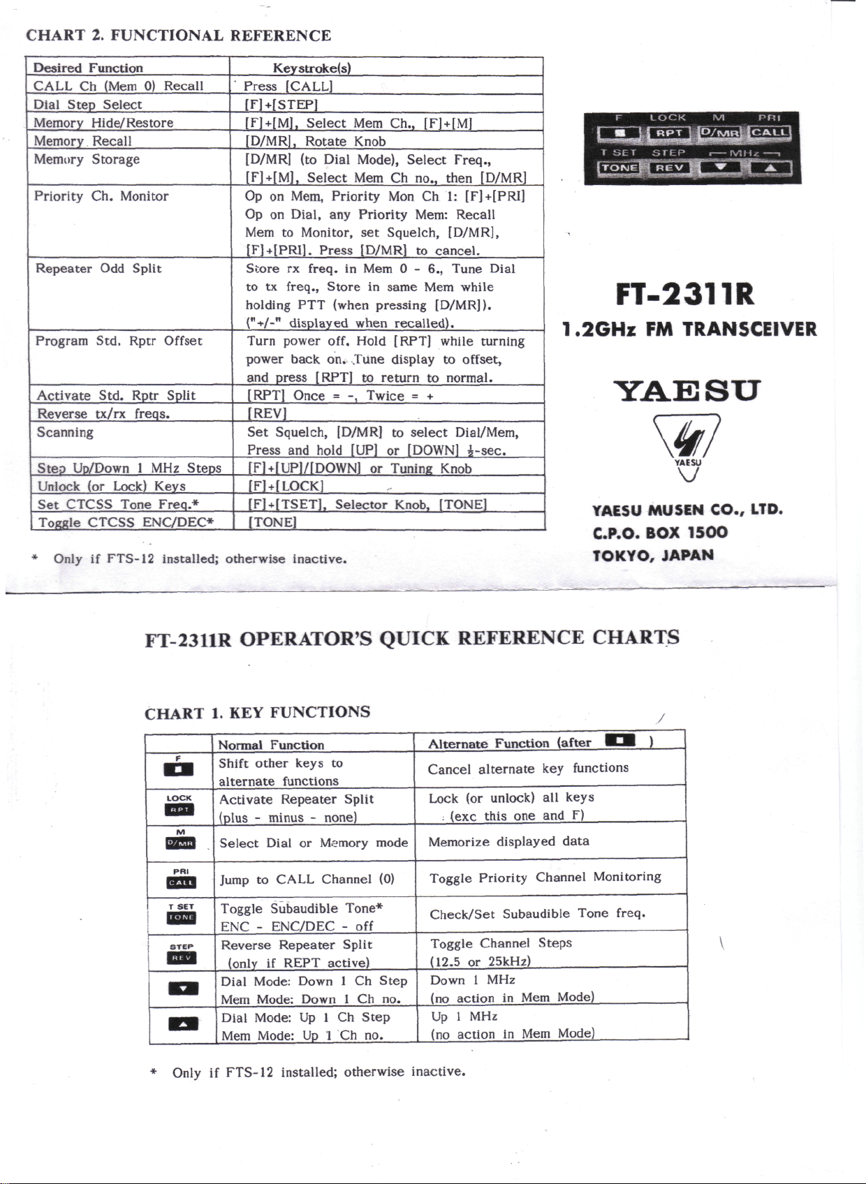
CHART
2.
FUNCTIONAL
REFERENCE
Desired
CALL
Dial
Memory
Memory
Memory
Priority
Repeater
Program Std. Rptr
Activate
Reverse
Scanning
Step Up/Down
Unlock
Set
ToKKle
Function
Ch
(Mem
Step
Select
Hide/
Restare
Recali
Storage
Ch.
Monitor
Odd
Split
Std. Rptr Split
tx/rx freqs.
1 MHz
(or
Lock)
CTCSS Tone
CTCSS ENC/DEC*
Only
if
FTS-12
Keystroke(s)
0)
Recali
Offset
Steps
Keys
Freq.*
installed; otherwise inactive.
Press
[CALL]
[FMSTEP]
[F] +
[M],
Select
[D/MR],
[D/MR]
[F] +
Op on
Op
Mem
[F] + [PRI].
Sìore
to tx
holding
("•*•/-"
Turn
power
and
[RPT]
[REV]
Set
Press
[F]+[UP]/[DOWN]
[F] + [LOCK]
[FHTSET],
[TONE]
Rotate
(to
[M],
Select
Mem, Priority
on
Dial,
to
Monitor,
rx
freq.
freq.,
PTT
display
power off.
back
press
[RPT]
Once
Squelch,
and
Mem
Knob
Dial Mode),
Mem Ch
any
Priority Mem:
set
Press
[D/MR]
in Mem 0 -
Stare
hold
in
(when
ed
when
Hold
on.
Tune
to
= -,
Twice = +
[D/MR]
[UP]
or
Selector
pressing
return
Ch.,
[F]+[M]
Select
Mon Ch 1: [F] +
Squelch,
same
recalled).
[RPT]
display
to
or
[DOWN]
Tuning
Knob,
Freq.,
no.,
then [D/MR]
[D/MR],
to
cancel.
6.,
lune
Mem
[D/MR]).
while
to
to
normal.
select
Dial/Mem,
Knob
[TONE]
Recali
while
turning
offset,
i-sec.
[PRI]
Dial
FT-2311R
1.2GHz
YAESU
C.P.O.
TOKYO,
FM
TRANSCEIVER
YAISU
V
MUSEN
BOX
JAPAN
CO.,
15OO
LTD.
FT-2311R OPERATOR'S QUICK REFERENCE CHARTS
CHART
f
LOCK
M
y2S3
T
SET
iTEP
«»
1. KEY
Normal
Shift
alternate
Activate Repeater Split
(plus - minus - none)
Select
Jump
Toggle
ENC - ENC/DEC
Reverse
Dial
Mem
Dial
Mem
FUNCTIONS
Function
other
keys
functions
Dial
to
CALL
Subaudible
Repeater
(only
if
REPT active)
Mode:
Mode:
Mode:
Mode:
to
or
Memory
Channel
Down
Down
Up 1 Ch
Up 1 Ch no.
mode
(0)
Tone*
- off
Split
1 Ch
Step
1 Ch no.
Step
Alternate
Cancel alternate
Lock
.
Memorize
Toggle Priority Channel Monitoring
Check/Set Subaudible Tone freq.
Toggle Channel
(12.5
Down
(no
Up
(no
(or
unlock)
(exc
this
or
25kHz)
1 MHz
action
1 MHz
action
Function
one and F)
displayed data
in Mem
in Mem
(after
key
ali
keys
Steps
Mode)
Mode)
functions
Di )
Only
if
FTS-12 installed; otherwise
inactive.
Page 2
f\
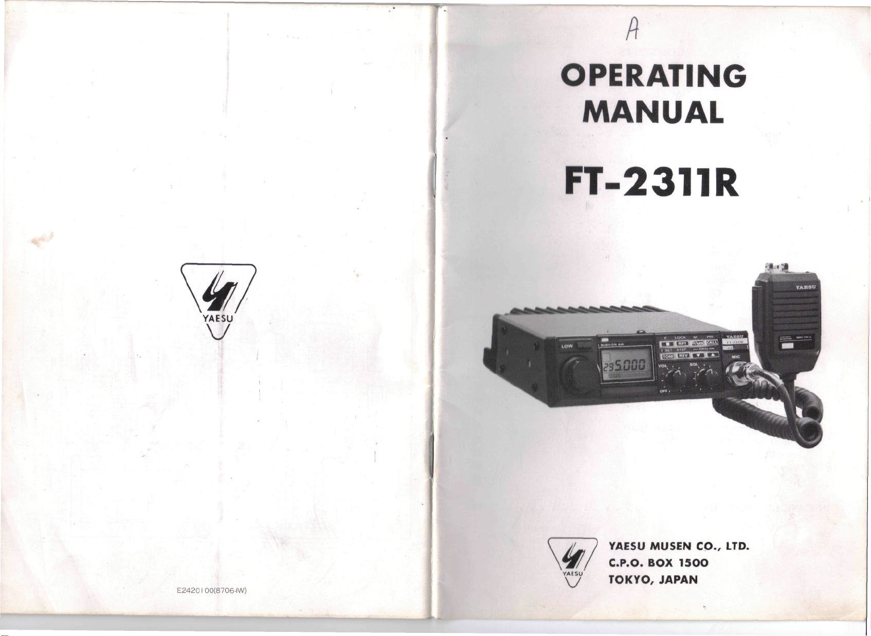
OPERATING
••
YAESU
V
MANU
AL
FT-2311R
Iti
\y
TOKYO,
YAESU
C.P.O.
MUSEN
BOX
15OO
JAPAN
CO.,
LTD.
Page 3
CONTENTS
SUPPLIED
ACCESSORIES
OPTIONS
SPECIFICATIONS
CONTROLS & CONNECTORS
FRONT
REAR
PANEL
PANEL
INSTALLATION
Antenna
Mobile
Front
Mobile
Considerations
Installation
Panel
Reversai
Power Connection
Base Station Installation
Packet
Radio
FTS-12
Memory
TNC
Interconnections
Tone Squelch
Cloning
Unit
OPERATION
Preliminary
Squelch
Transmitting
Operating
Setup
Procedure
Information
Frequency & Step Selection
Memory
Storage & Recali
Repeater Operation - Standard Splits
Non-Standard
Repeater Splits
Scanning
Priority Channel Monitoring
Tone Squelch Operation
IN
CASE
OF
PROBLEMS
Installation
10
11
12
14
15
16
16
16
17
18
18
20
21
22
23
24
25
YAESU
COMPACI
1.2 GHz FM
The
FT-2311R
providing
thè
The
and
thè
switch-selectable power output
1.2 GHz
reversible sloped
includes
large
liquid
FT-2311R,
9
ability,
while
Operating features similar
both
pushbutton
steps;
ten
reverse
and
auto-resumé
FT-2311R,
oscillator
channel
Any
seven
When
(TCXO)
accuracy
standard
can
thè
standard CTCSS
and
programmed into
or
encode-only
The
microphone jack includes
packet radio
modification).
operating requirements.
is a
compaci
amateur band.
front
panel
soft
green
crystal
extensive
modular
back-lighting
display
use of
circuii
to
and
knob memory selection
memory channels storing
cali
channel recali; band, memory
scanning
and
supplied
and
priority channel monitoring. Unique
as
standard,
stable within
repeater
also
within
store
±2 kHz on
shift
can be
independent transmit
optional FTS-12 Tone Squelch
(subaudible)
any
tone frequencies
memory channel
operation.
tnc
(not supplied, European version
Six
different
For
FT-2311R
SYNTHESIZED
MOBILE TRANSCEIVER
synthesized
allows convenient overhead
(with
chip components assures
construction
thè
popular
repeater
is a
±1.5ppm
thè
programmed into
ali
signals needed
microphones
thè
European version, a 1750
FM
mobile/base transceiver
of
either
of
thè
bargraph
5* or 10
keys
and
PO/S-meter).
high
makes
FT-23R/73R
servicing
and
tuning
Handhelds
splits; one-touch
and
partial memory
temperature-compensated crystal
between
1.2 GHz
O and
band.
50°C;
ali
and
receive
Unit
is
installed,
can be
for
either
for
displayed,
sileni
connection
may
are
available
watts
on
mounting,
controls,
circuii
Inside
and
thè
reli-
easy.
include
in
selectable
repeater
to
thè
maintaining
memories,
and
frequencies.
any of 37
selected
monitoring
of a
require slight
for
particular
Hz
burst
I-watt
low
power
in
version
B
- 1 -
Page 4
tone generator
or
MH-14A8 Speaker/Mie
microphone
own
auto-dial
Along
with
supplied
AC
Please
with
Power Supply/External Speaker
read this
SUPPLIED
MMB-33
Power Supply Cable
One of
is
built-in,
and can be
(if not
options include
memories.
one
microphone,
thè
transceiver.
manual
before
ACCESSORIES
Mobile
thè
microphones listed below.
Mounting
T9015610
OPTIONS
FTS-12
SP-55
MH-10E8
MH-10F8
MH-14A8
MH-15C8
MH-15D8
MF-1A3B
YH-1
SB-10
Tone
Squelch
External
Standard
Hand
Speaker/Mie
Hand
Speaker/Mie w/Burst
Hand
Mie
Hand
Mie
Boom
Microphone
Headset
PTT
Switch Unit
Unit
Speaker
Hand
w/DTMF keypad
w/DTMF Autodialler Memory
(w/microphone)
modified
thè
MH-15C8
thè
MMB-33
For
base station
is
optionally
installing
Bracket
with
two 10A
Microphone
with
flexible
for
MF-1A3B
activated
and
for
from
packet).
thè
MH-15D8
thè
front
DTMF
with
Reversible Mobile Bracket
installations,
thè
available.
or
operating
thè
FT-2311R.
fuses, 2.8m
Button
arni
or
YH-1
panel
keypad
its
is
FP-700
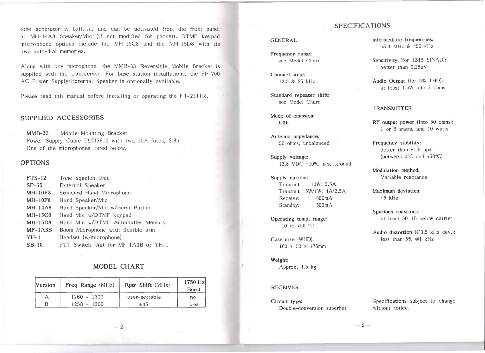
GENERAL
Frequency
Channel
Standard
Mode
Antenna
Supply
Supply
Operating
Case
range:
see
Model
steps:
12.5
& 25 kHz
repeater
see
Model Chart
of
emission:
G3E
impedance:
50
ohms, unbalanced
voltage:
13.8
VDC
current:
Transmit
Transmit
Receive:
Standby:
temp.
-10 to +50 °C
size
(WHD):
160 x 50 x
SPECIFICATIONS
Chart
shift:
±10%, neg. ground
10W:
5W/1W:
660mA
SOOmA
5.5A
4A/2.5A
range:
175mm
Intermediate
58.3
Sensitivity
better
Audio Output (for
at
TRANSMITTER
RF
output
1
or 5
Frequency
better
(between
Modulation
Variable
Maximum
±5
Spurious
at
Audio
less
frequencies:
MHz & 455 kHz
(for 12dB
than 0.25uV
least
1.5W into 8 ohms
power
watts,
stability:
than
±1.5
0°C
method:
reactance
deviation:
kHz
emissions:
least
50 dB
distortion
than
5% ®1 kHz
SIN
5%
THD):
(into
and 10
ppm
and
+50°C)
below
(@3.5
AD):
50
ohms):
watts
carrier
kHz
dev.):
Version
A
B
MODEL
Freq Range (MHz)
1260 - 1300
1258 - 1300
CHART
Rptr Shift (MHz)
user-settable
±35
O
1750
Burst
no
yes
Hz
Weight:
Approx.
RECEIVER
Circuit
Double-conversion
1.5 kg
type:
superhet
- 3 -
Specifications
without
notice.
subject
to
change
Page 5
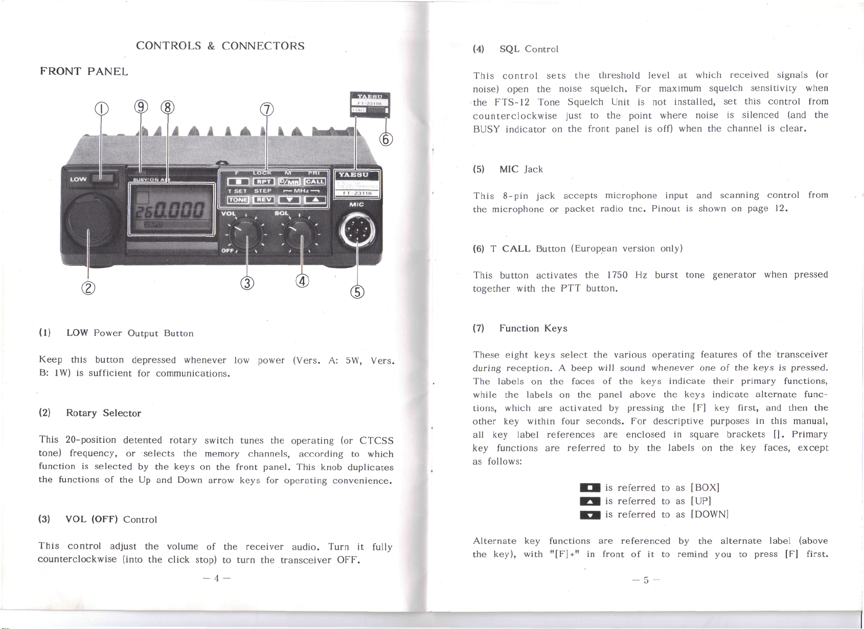
CONTROLS & CONNECTORS
(4)
SQL
Control
FRONT PANEL
(1)
LOW
Keep
B: 1W) is
(2)
Rotary
This
20-position
tone) frequency,
function
thè
functions
(3)
VOL
Power Output Button
this button
sufficient
Selector
detented rotary switch tunes
or
is
selected
of
thè
(OFF) Control
depressed
for
Communications.
selects
by
thè
keys
Up
and
whenever
thè
on
Down arrow keys
low
power (Vers.
thè
operating
memory channels, according
thè
front
panel.
for
operating convenience.
A: 5W,
(or
This knob duplicates
CTCSS
to
which
Vers.
This control
noise)
open
thè
FTS-12
counterclockwise just
BLJSY
indicator
(5)
MIC
This
8-pin
thè
microphone
(6) T CALL Button (European version
This
button
together
(7)
Function Keys
These
eight keys
during
reception. A beep
The
labels
while
thè
tions,
which
other
key
ali
key
key
functions
as
follows:
sets
thè
noise squelch.
Tone Squelch
on
Jack
jack
or
activates
with
thè
on
thè
labels
are
within
label
references
are
thè
threshold
to
thè
front
accepts
packet
thè
PTT
button.
select
on
activated
four
thè
faces
thè
panel above
seconds.
referred
level
For
Unit
is not
thè
point where noise
panel
is
microphone input
radio tnc. Pinout
1750
Hz
various operating features
will
sound whenever
of
thè
keys indicate their primary functions,
by
pressing
For
descriptive purposes
are
enclosed
to by
is
is
is
thè
referred
referred
referred
at
which
maximum
installed,
off) when
and
is
only)
burst tone generator when
thè
keys indicate alternate func-
thè
[F] key
in
square
labels
to as
to as
to as
[BOX]
[UP]
[DOWN]
received
squelch sensitivity when
set
this control
is
silenced (and
thè
channel
scanning control
shown
one of
on
on
of
thè
first,
brackets
thè
key
signals
is
clear.
page
12.
thè
transceiver
keys
is
and
in
this manual,
[].
faces,
(or
from
thè
from
pressed
pressed.
then
thè
Primary
except
This control adjust
counterclockwise (into
thè
thè
volume
click stop)
of
thè
to
- 4 -
receiver
turn
thè
audio. Turn
transceiver
it
OFF.
fully
L
Alternate
thè
key), with
key
functions
"[F]+"
in
are
referenced
front
of it to
- 5 -
by
thè
remind
alternate label (above
you to
press
[F]
first.
Page 6
For
example,
followed
described
Operator's Quick Reference Charts.
(8)
LCD
The
display shows
thè
following
by
thè
in
detail
(Liquid
diagram.
"[F]+[UP]"
13
key
in
thè
Crystal Display)
thè
selected
The
indicates
within
OPERATION
1-GHz
frequency digit
that
you
should
four
seconda.
section,
operating conditions
press
Ali
key
and
summarized
is not
thè
[F]
functions
as
indicated
displayed.
key,
in
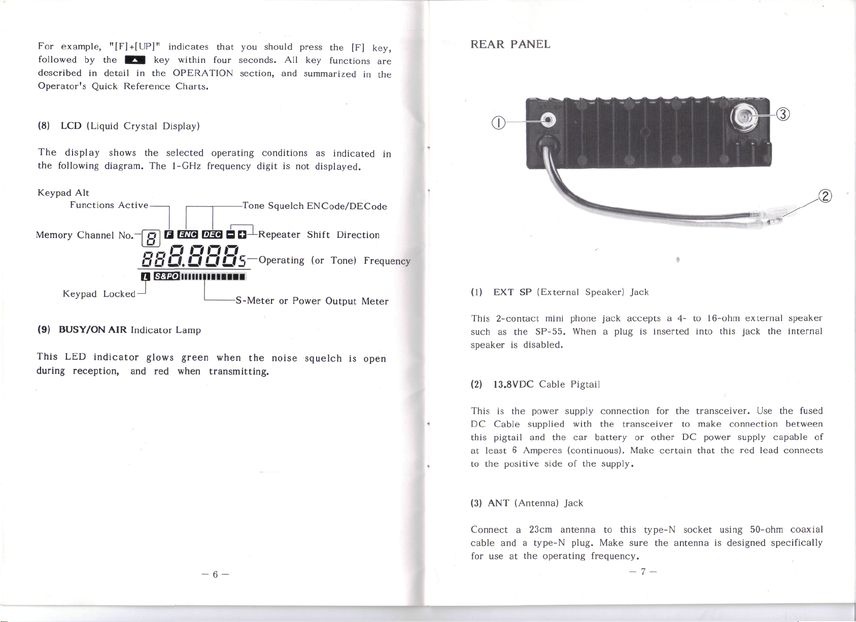
REAR PANEL
are
thè
in
Keypad
Functions Active-
Memory
Keypad
(9)
BUSY/ON
Tnis
LEO
during
reception,
Alt
Channel
Locked
indicator
No.~
AIR
Indicator
and red
-Tone
Squelch ENCode/DECode
Q
1377*1
Préa B D^-Repeater
^7
O
O
OuU.UUUb~Operating
O O
arnsì
glows
-S-Meter
Lamp
green
when transmitting.
when
thè
or
noise squelch
Shift Direction
(or
Tone)
Power
Output
is
Frequency
Meter
open
(1)
EXT SP
This
2-contact
such
as
speaker
(2)
13.8VDC Cable Pigtail
This
is
DC
Cable
this
pigtail
at
least 6 Amperes (continuous). Make certain that
to
thè
positive side
(External Speaker) Jack
mini
phone jack
thè
SP-55.
is
disabled.
thè
power
supplied
and
When a plug
supply
with
thè
car
of
thè
battery
accepts
is
connection
thè
transceiver
or
supply.
a 4- to
inserted
for
thè
to
other
into
transceiver.
make
DC
16-ohm
power
external speaker
this jack
connection between
thè
Use
supply
red
lead
thè
internai
thè
fused
capable
connects
of
- 6 -
(3)
ANT
(Antenna)
Connect a 23cm antenna
cable
for
use at
and a
type-N plug. Make sure
thè
Jack
operating frequency.
to
this type-N
- 7 -
thè
socket
antenna
using
is
50-ohm
designed specifically
coaxial
Page 7

INSTALLATION
Antenna
The
near
use a
connected
otherwise result
is
Another important consideration
FT-2311R
possible
to use a
ceiver.
Mobile
The
electrical
play, controls
securely
The
affecting
vent
Make
ceiver
diagrams
thè
Considerations
FT-2311R
50
ohms
high-quality,
at
ali
connected.
is
thè
length
properly matching
Installation
FT-2311R
System.
affixed
transceiver
its
performance,
or
where
sure that plenty
so
that
on
thè
transceiver
overhead),
is
designed
at
thè
carefully
times when power
if
feedline.
of
thè
must
The
and
using
may
it
could
air can
facing page
for use
operating frequency.
designed antenna.
transmission
For
best
quality coaxial cable available,
fitting
only
be
installed
transceiver should
microphone
thè
supplied
be
installed
but it
interfere
of
space
flow
freely around
for
and
installation
occurs
optimum performance
are
should
is
reversai
with
an
is on, to
accidentally when
in
installing
(type-N)
in
cars
easily
MMB-33
in any
not be
with
safe operation
provided
of
of
antenna having
For
optimum performance
The
avoid damage
thè
for
thè
having a negative ground
be
located
accessible,
mobile
position without adversely
mounted near a heater
at
thè
rear
thè
heatsink. Refer
thè
front
thè
MMB-33.
an
impedance
antenna should
that
no
antenna
antenna
use
jack
where
and
mounting
of
panel
thè
and be
on
thè
thè
should
thè
of
thè
(if
for
shortest
trans-
bracket.
vehicle.
trans-
to
installing
sure
dis-
be
can
thè
be
thè
«
Front
Panel
The
front
supplied
installation
(1)
from
Remove
remove
|-
f
.-
Reversai
panel
may be
thè
factory),
requirements.
thè
ten
thè
covers,
installed
To
screws
using
so
or
downward,
reverse
affixing
care
not to
that
thè
thè
it is
front
panel;
top and
strain
angled either upward
to
accommodate various
bottom
thè
covers,
speaker
and
wires.
(as
(1)
Use
thè
mounting
sufficient
bit
for
drilling
washers
on
and
page 10).
mounting
holes,
clearance
after determining
thè
nuts supplied,
bracket
for
thè
holes.
as a
Secure
tempiale
transceiver.
thè
as
shown
- 8-
for
positioning
thè
proper location with
Use a
bracket
in
Figure
4.8mm
with
1.
thè
(Continued
thè
(3/16")
screws,
(2)
Remove
separate
(3)
Using
thè
(4)
Replace
ten
thè
it
care
front
panel
thè
screws.
four
from
thè
not to
over,
top and
screws
chassis.
pulì
and
bottom
affixing
on
thè
remount
covers
- 9 -
thè
front
panel,
interconnecting wiring, turn
it.
(now
also
reversed)
and
and
gently
their
Page 8

Do
not
fused
are
their
connect
cable,
to
any
power
and do not
protect
you and
to
thè
attempi
thè
transceiver
to
defeat
equipment.
or
except
bypass
via
thè
thè
fuses - they
supplied
(2)
Position
thè
bracket,
short screws
Mobile
Before
should
is run
be
adjusted before connecting
thè
side panels
and
Power
Connection
connecting
be
checked
fast.
If
more than 15V,
transceiver
are
bolt
thè
and
fiat
thè
power cable
to
ensure that
Power connections should
using
thè
supplied
cigarette
blow
in
lighter
that
circuii.
battery independently
will
minimize
possible
drop during transmission,
cable
or
other
Connecting
of
ignition
while
MMB-33
in
thè
aligned
bracket
with
those
so
in
that
thè
transceiver into piace with
washers.
thè
it
thè
thè
transceiver.
be
made directly
with
10A
accessory
thè
thè
rest
noise pickup
allowing
maximum
remains
voltage regulator
in-line
circuii
supplied
of
thè
operation with
battery charging voltage
below
to
thè
fuses. Connection
may
DC
automobile
and
excessive
Figure
1.
Installation
thè
sides
15V
of
holes
thè
when
thè
in
of
thè
supplied
thè
engine
car
should
automobile battery
to
cause
power cable
thè
electrical
supply
thè
ignition
fuse
to
System
voltage
off.
thè
to
thè
Connect
tery
it
terminal,
is
necessary
thè
RED
and
to
lead
thè
BLACK
extend
of
thè
thè
power
lead
power
insulated, stranded copper wire,
power
cable
length practicable
to
-WARNING-
NEVER
JACK
OF
REPLACE
THESE
The
SP-55
source
hearing. Especially practical
SP-55 includes
from
your Yaesu
operating
microphone,
arm
(both
Base
Station Installation
Mounting
station. A power
at
13.8VDC
speaker
from
your Yaesu dealer
cable supplied with
connect
APPLY
OF THE
MORE
THAN
FUSES
PRECAUTIONS
External Speaker
of
audio
from
its own
dealer.
convenience
and
thè
of
which
feet
are
supply
is
required
is
recommended.
thè
external speaker
AG
POWER
TRANSCEIVER.
15
VOLTS
WITH
10A
WILL
is an
thè
transceiver
for
swivel-type
Also
available
are
thè
full
size
MF-1A3B
use
thè
SB-10
supplied
for
thè
capable
for
operation
The
FP-700
for
this purpose.
thè
transceiver
to
thè
cable
to
cable,
and in
to
thè
thè
NEGATIVE
use #14 AWG or
ali
cases
keep voltage drop
TO THE
NEVER
TO THE
RATING.
VOID
optional
thè
mounting
YH-1
REAR
PANEL
CONNECT
POWER
JACK.
FAILURE
THE
WARRANTY.
accessory
to be
repositioned
noisy mobile environment,
bracket,
to
enhance safety
Headset
with miniature boom
boom microphone with
PTT
switch).
transceiver when used
of
providing
from
AC
for
making
EXT SP
at
least
thè
AC
line,
power supply
Use
thè
power connections,
jack
on
POSITIVE
(-)
terminal.
use
thè
minimal.
POWER
DC
VOLTAGE
ALWAYS
TO
OBSERVE
which allows
for
and is
and
as a
6 A
continuously
and an
is
fused
thè
DC
rear
(+)
bat-
larger
minimum
thè
optimum
thè
available
mobile
flexible
base
external
available
power
and
panel.
If
-10-
Page 9

Racket
Most
thè
Use
cable
Modification
Radio
TNC
popular packet radio
FT-2311R
TNC
Receiver
Squelch
PTT
Transmit
as
Transceiver Jack
Audio
Ctrl
(gnd=tx)
Audio
shielded cable
as
short
as
VERSION A VERSION
for
Packet
Interconnections
tncs
follows:
in
in
out
out
for
thè
audio
possible
MIC
to
avoid
r\—
MIC
Radio
can be
pin
pin
pin
4 (8
5*
6
connected
FT-2311R
ohms,
(open=8V,
to
thè
MIC
Jack
de-emphasized)
closed=OV 1 mA)
pin 8 (400 ohms, pre-emphasized)
lines,
RF
Q6O5
2SC1623
and
pickup.
keep
thè
interconnecting
B
MIC
jack
of
(1)
Remove
remove
(2)
Remove
separate
thè
CNTL
(3)
Cut
thè
thè
CNTL
of
thè
(4)
Referring
thè
point indicate
pin
5 of
interfere
(5)
Replace
top and
CNTL
DH
thè
ten
thè
covers,
thè
four
it
from
Unit
green wire
Unit,
way.
to
thè
thè
with
installation
thè
front
bottom
Unit(lnside
front panel)
screws
without
affixing
using
care
screws
thè
chassis, just
straining
not to
affixing
at pin 5 of
and
carefully
diagram
on
MIC
covers
below,
thè
solder
jack. Route this wire
of
thè
panel
and
and its
their
thè
thè
thè
thè
tape
top and
strain
enough
wiring.
MIC
thè
bottom covers,
thè
front
panel,
to
jack
end of
connect a 200mm
side
of
thè
so
covers.
four
screws,
ten
screws.
speaker wires.
and
gently
gain
access
on
thè
rear
this wire
wire between
Main
that
it
and
Unit
wijl
then
and
and
to
of
out
not
thè
In
thè
European version (B),
with
thè T CALL button
vation
from
thè
microphone. This feature
radio operation, however,
of
thè
(not
equipped
wired
cation
front
panel.
in
from
Squelch
this way.
in
European versions,
thè
thè
detect
with
a T
The
tone burst
European version (B), this
microphone.
on
pin 5 of
thè
front
thè
panel
so pin 5 may be
line
for
packet radio
CALL button
may
but
stili
only
or
be
by
pin is
It
can be
modified
-12-
MIC
jack
is
to
accept
is not
rewired
tncs.
generator),
wired
needed
to
In
pin 5 is
in
tone burst
for
provide
other version
activated after this
thè T CALL button
wired
as
for
follows;
Burst control
parallel
acti-
packet
output
already
modifi on
thè
-13-
Page 10

FTS-12
The
with
able
"Operation" section
(1)
(2)
(3)
Tone Squelch
FTS-12 provides either
37
front
for
ali
versions
panel
selectable
FT-2311R,
for
Disconnect
remove
thè
cover
and
lay
Installed
position,
bands).
thè
transceiver, this resistor
gray
Align
thè
hole
thè
power cable
thè
five
carefully
thè
set
upside down.
on
thè
unused
notice a 27-kilohm
Remove this resistor.
and
blue
leads).
thè
small
tab on one
in one
side
connectors.
Unit
Installatici!
encode-only
subaudible
from
functional
at
screws
affixing
so as not to
10-pin
of
thè
or
encode/decode operation
CTCSS tones,
your locai Yaesu
details.
thè
rear
of
thè
thè
bottom
pulì
on
thè
plug
near
thè
resistor
If
must
side
(red,
thè
FTS-12
be
reinserted (between
of
thè
violet
is
10-pin connector
FTS-12 connector,
and is
dealer.
transceiver,
cover*.
Remove
speaker wires,
FTS-12
mounting
and
orange
removed
and
mate these
avail-
See
and
from
thè
with
thè
Memory
Ali
by
gether
destination
When
source
operation
repeat).
Cloning
memory data stored
setting
thè
as
indicated
CLONE switches
transceiver,
transfer
is
completed,
transceiver
was
successful (otherwise, press
When
finished,
in
thè
and
will
return
in one
diagram
then
thè
appear
thè
CTCSS
67.0
71.9
74.4
77.0
79.7
82.5
85.4
88.5
91.5
94.8
transceiver
on and
below.
thè
El
data
on
thè
can be
connecting
Press
key on
from
Memory
destination transceiver
thè
CLONE switches
RESET
Ione
Frequency (Hz)
100.0
103.5
107.2
110.9
1
14.8
118.8
123.0
127.3
131.8
136.5
thè
thè
141.3
146.2
151.4
156.7
162.2
167.9
173.8
179.9
186.2
192.8
moved
thè
^31
to
MIC
key on
another
jacks
source transceiver.
channel
O in
of
arrow keys again
to
thè
OFF
position.
203.5
210.7
218.1
225.7
233.6
241.8
250.3
—
—
-
to-
thè
thè
thè
to
(4)
Now
inside
tape,
locate
of
thè
and
below.
(5)
Replace
FTS-12)
so no
If
thè
adjustment
thè
front
bottom
thè
is
speaker. Otherwise,
thè
double-sided
side panel. Remove
press
thè
FTS-12 against
bottom
adjusted
panel
panel
cover.
at
should
has not
is
thè
thè
thè
be
larger panel
bottom panel
adhesive
tape
thè
paper covering
it as
The
output tone
factory
for
necessary.
been reversed
which
is
thè
-14-
pre-installed
shown
thè
(ie.,
in
thè
level
(VR1
proper deviation,
angles
includes
smaller
one.
on
thè
from
this
diagram
on
thè
upwards),
thè
loud-
OFF
—
T
CLONE
»—
ON
Page 11

This chapter
After
studying
describes
these
descriptions, keep
Reference Charts handy
Preliminary
Before operating
connections. Never
Operating
thè
operate
Information
OPERATION
thè
various transceiver functions
in
case
you
transceiver,
thè
transceiver without
thè
need
to
recheck
in
FT-2311R
Operator's Quick
refresh your memory.
power supply
an
and
antenna.
antenna
detail.
a
signal
thè
Note that
along
reaches
indicator
while
thè
bottom
thè
will
glow
receiving,
receiver
green.
of
thè
that
is
strong enough
one or
more
display, indicating signal strength
receiving frequency. This indication
setting,
notice
squelch
you
so
more than
is
stili
want
to
even squelched signals
one or two
closed,
try
bargraph
reducing
hear weak signals).
will
to
open
bargraph
is not
segments
affected
by
have some indication.
segments
thè
squelch control setting
appearing while
thè
may
thè
squelch,
appear
on
thè
squelch
If you
thè
(if
Before proceeding,
if
you
have
thè
controls. Note especially
ogy
used when referring
When
thè
function
will
sound
is
invalid. Except
are
disabled during transmission.
If
you
'In
Case
Squelch
if
have trouble getting
of
Problems'
Setup
Before turning
terclockwise.
adjust
for
comfortable volume
BUSY/ON
turn
Rotate
silenced
thè
thè
AIR
selector
SQL
and
clockwise, sensitivity
please
not
already,
keys
thè
command
for
certain special
on
on
thè
Now
rotate
indicator
knob
to
control clockwise
thè
LEO
to
to
page
transceiver,
LEO
turns off.
weak signals
read
thè
to
familiarize
on
thè
are
pressed
is
accepted,
thè
chapter
page 5 thè
keys
in
transceiver
on
Controls & Connectors,
yourself
description
this
manual.
during reception, a single beep
or a
doublé
cases
mentioned
to
work
25.
set
thè
SQL
thè
VOL
should
on
control
thè
noise
glow
out of
or
green.
select a frequency where
just
to
thè
point where
If
thè
SQL
control
will
be
reduced.
with
thè
of
beep
if
later,
as
described,
control
thè
click-stop
received
If a
signal
only
noise
is set
Now, whenever
functions
thè
terminol-
thè
command
thè
fully
coun-
signal.
is
present,
is
heard.
thè
noise
further
of
keys
see
and
The
is
Transmitting
Press
thè
transmit,
thè
PTT
AIR
indicator
transmitter power output.
If
more
Procedure
LOW
wait
until
switch
will
power
button
thè
on
thè
glow red,
is
required,
to
select
channel
low
power output.
is
clear
(green
microphone. During transmission
and
thè
bargraph
Release
set
thè
thè
PTT
LOW
position. However, whenever communication
keep
thè
LOW
button
depresseti
to
minimize
other stations.
If
using a version
thè
front
panel
Burst Tone
If
version
on
thè
panel
to
to
microphone
B (in
or
thè
access
is
modified
transmit
Europe),
MH-14A8
repeaters
for
is
disabled
thè
burst
press
thè T CALL button, either
microphone*,
that require
packet
radio,
- use
tone.
When
you
LED
off),
and
thè
will
now
show relative
switch
to
receive.
button
is
to
possible with
thè
undepressed
possible interference
to
transmit a 1750
it.
thè T CALL button
thè
button
on
thè
wish
squeeze
BUSY/ON
low
power,
front
to
to
on
Hz
-16-
-17-
Page 12

Frequency & Step
To
tune
to a new
must
be in
left
corner
There
thè
selector
[UP]
(press
Channel
step
size
played
One-megahertz
thè
selector
Memory
The
FT-2311R
through
thè
upper left
(1)
Tune
thè
Dial
of
thè
are two
or
[DOWN]
one of
steps
to
at
thè
Storage & Recali
9.
to
ways
knob,
these
are
thè
right
steps
knob
offers
When
corner
thè
Selection
frequency
mode.
display,
to
or
with
key*
keys
12.5
other
press
end of
are
or
pressing
ten
in
thè
of
desired
or
change
If a Memory number
press
select
thè
for
again
or 25 kHz in
[F]+[STEP]*. A small
thè
also
programmable
Memory mode,
thè
display.
frequency
[D/MR]
your operating frequency:
[UP]
and
more than
to
stop).
ali
frequency
available:
thè
[UP]/[DOWN]
To
in
thè
tuning
i-second
versions.
on
just
memory channels,
thè
store a frequency
Dial
steps,
is
present
to
select
[DOWN]
alternate
press
keys.
Memory number
mode.
thè
keys.
will
To
change
.5 kHz
12.5
[F]
thè
transceiver
in
thè
upper
Dial
mode*.
by
turning
Holding
start
digit
kHz
before turning
numbered
appears
in
memory:
thè
scanning
from
one
is
dis-
steps.
O
in
Once
thè
Memory number
maximum
you
be
displayed after
Remember that when
in
that
EXAMPLE:
(1)
Press
(2)
Press
(3)
Press
To
recali
in
thè
necessary,
is
now be
of
four
seconds
press
[D/MR]
memory
to
[D/MR]
thè
Dial
keys
to
select
[F] + [M] and
displayed
[D/MR].
played.
step
If
2).
prestored
Memory mode (Memory number displayed).
to
recalled.
in
you
is
erased.
store
once
mode.
Then
295.000
(blinking)
There
there
select
between knob
step
(3).
press
you
store a memory,
1295.000
if a
use
on
then
at
thè
should
is, you
memories
thè
timed
Memory
starts
[D/MR].
MHz in
Memory number
thè
thè
rotate
upper left
blinking
If you
for
time
channel
selector
display*.
thè
now be no
out
(press [D/MR]
operation,
mode.
selections
Simply
knob
selector
corner.
The
in
step
(2),
you
have
or
keystrokes
out, a memory number
start
again
any
data
O
is
displayed,
or
[UP]
knob
rnemory number dis-
and
thè
transceiver
Press
last
memory channel
at
step
previously
to
select
and
[DOWN]
until
'O'
then
repeat
must
[D/MR],
stored
is
a
until
will
(2).
be
if
used
(2)
Press
(3)
Press
[F] + [M]
desired
or
Memory:
will
If
small
[F] +
Memory number
[UP]/[DOVVN]
[D/MR]
thè
continue
nothing happens when
'L' at
[LOCK]
in
thè
to
(thè
Memory number
for
Storage using
keys,
to
store
thè
Dial frequency into
Memory number
thè
Dial mode.
you
lower
left
corner
unlock
thè
keys.
-18-
will
blink)
will
disappear,
press a key,
of
thè
display.
and
thè
selector
and
see if
select
thè
selected
operation
there
If so,
thè
knob
is a
press
Rotate
thè
memories.
skipped.
Note:
instantly
when
To
exit
*
Remember,
Only
Memory
recalled
finished
thè
selector
prestored
O is a
from
to
return
Memories
thè
knob
special
any
to
and
1-GHz
or
press
memories
'Cali
mode just
thè
previously
return
digit
to
is not
-19-
thè
up/down keys
are
displayed:
Channel
by
pressing
selected
Dial mode,
displayed.
empty
Memory1,
[CALL].
mode.
press
[D/MR].
to
select
memories
which
Press
other
are
can be
[D/MR]
Page 13

Repeater
The
key, which
modes.
but in
on a standard
than
med,
(1)
(2)
(3)
(4)
Before activating
on
for
'
+ '
again
corner
switch
down,
ham
You
pressing
receive
band).
Operation - Standard
FT-2311R
In
version A thè
35 MHz in
as
follows;
Turn
Press
back
programmed standard
Use
thè
set
thè
area.
[F]
and
this point
Press
as
thè
which
'-'
shift
shift
will
when standard
is
if in
band,
can
thè
frequencies
If
provides a 'standard
activates a pre-programmed
(European) version B thè
repeater
thè
transceiver
and
hold
on.
'-+'
[F] key and
display
For
example,
turn
it
[RPT] again.
display returns
you
receive
(to
(to
transmit
return
pressed
band.
'Err1 is
check
PTT
both
receive
Splits
pre-programmed offset
split using version
version
thè
doesn't
repeater
transmit
to
to
thè
B,
thè
standard split offset must
off.
thè
[RPT]
will
appear,
repeater
to
thè
if you
selector
matter
The
to
thè
below
above
simplex.
repeater
transmit,
If
thè
resulting transmit frequency
displayed instead.
frequency
switch:
(if
nothing happens,
and
key
blinking,
selector
standard
need
knob
whether
'-+'
what
split, tune
repeater's
your
your
'-' or
thè
just
press
transmit frequencies
split'
feature,
offset
pre-programmed offset
while
along
offset.
knob
or
repeater
20 MHz
for
20.000
thè
on
thè
display
was
shown before
thè
Dial mode
signals. Then
receive
receive
'+'
is
split
is
selected,
displayed frequency
to be
used
[REV],
thè
selected
in
both
is O
A, or
turning
with
[UP]/[DOWN]
offset used
standard split,
on
split
is + or -).
will
frequency),
frequency).
displayed
for
to
reverse
selected
are in
by
thè
[RPT]
Dial
and
Memory
is 35
MHz.
So, to
with
an
offset other
be
thè
transceiver
thè
currently
keys
in
thè
display
stop
blinking
step
1.
to
thè
press
and
transmission without
Pressing
at
thè
when
will
is
offset
band,
[RPT]:
and
shift
outside
transmit
MHz,
operate
reprogram-
to
your
press
(at
frequency
once
again
for
[RPT]
upper right
thè
PTT
up or
of
thè
and
is
out-of-
thè
'-' or
V
displayed
mit
and
also
allows
can
work a particular station
Press
[REV] again
Storing a memory while standard
Dial
mode
along
with
recalled,
The
REVerse
[RPT]
and
ation
on
shift
functions
ries,
if
Non-Standard
Memories O through
for
operation
storè
thè
Dial
to
but
this
[D/MR]
when
you
upper right.
sing
thè
channel
grammed
When
offset,
at
thè
programmed,
thè
from
at
thè
upper right
receive
thè
that memory:
required.
receive
thè
time
thè
recali
[RPT]
simplex. Pressing [RPT] again
standard split offset
memories O through
they
[RPT]
thè
frequencies
you to
will
thè
stored
[REV]
Repeater
desired transmit frequency,
last
The
time they
Dial mode.
check
to
return
cause
displayed frequency*. Then whenever that memory
shift
function
can be
can
also
6 can
on
repeaters
frequency
hold
thè
time while
thè
memory,
[REV]
key
will
will
retain
these
key is
are
thè
direct
to
thè
offset
will
be
cannot
pressed
thè
new
be
activated
Splits
also
with
as
PTT
switch
key
will
disable
thè
are
stored.
memories
used,
or
reversed.
repeater
thè
(amount
active
be
store
non-standard shift.
described
thè
'-+'
function
thè
(in
6 are
offset which
will
thè
will
blink,
(on a
originai
repeater
stored
to
temporarily change
setting
while operating
an
and
at
Memory number
will
non-standard split
will
piace
stored
If
not
memories
signifying
Using this REVerse
input
(thè
independent transmit frequency,
thè
thè
frequency
simplex frequency,
repeater
split
and
direction)
'-' or '+'
in
memory, although both
will
not be
previously. Then retune
repeat
be
as
of
thè
last
step
displayed
described above,
activate
thè
with standard
was
standard offset
"know"
are
that
to see
split direction.
is
activated
to be
will
be
repeater
stored.
on
simplex
To do
Storage
(when
is
blinking).
together
and
thè
currently pro-
independent transmit
pre-programmed
about
it
restored
thè
trans-
function
if
of
course).
in
stored
displayed).
oper-
Repeater
memo-
this,
procedure,
you
press
at
but
pres-
make
repeater
is re-
unless
again
you
thè
is
first
thè
Now
thè
thè
-20-
-21-
Page 14

frequency).
and
then
To
recali
return
thè
memory
Scanning
Before starting
off
thè
noise
are
available: band scanning
ning
is
manually
key. Just
scanner.
result.
Memory
The
on any
squelch,
prefer
after
inside
If a
mode,
scanner
channel where a signal
and
to
thè
thè
thè
scanner
on a
clear
activated
press
If
and
thè
transceiver
hold
memory number
and
only
is
preset
then resumé scanning (this
have
thè
scanner
channel
top
becomes
cover
to
to
thè
again.
make
channel.
or
and
thè
key for
is in
prestored
at
thè
factory
stay
clear), move
position
odd
split
press
sure
thè
SQL
Two
different
memory scanning.
deactivated
by
more than
thè
Dial
mode, band scanning
is
displayed,
memories
is
found
paused
B. See
to
thè
will
pause
strong enough
is
SCAN mode
on a
channel
thè
SCAN mode
thè
photo
[D/MR]
control
is set to
modes
In
both modes,
thè
[UP]
ì-second
transceiver
be
scanned.
for up to
(until
below.
twice,
of
scanning
or
[DOWN]
to
start
to
is in
five
seconds
to
open
A). If you
two
selector
quit
squelch
scan-
thè
will
thè
thè
seconds
switch
For
memory scanning,
certain
Memory
memory
blinking.
can no
To
hide
[F]+[M]
Priority
The
memories.
0)
without erasing
to
hide,
The
display
longer
be
unmask a hidden memory,
it:
press
[F] +
again.
Channel Monitoring
Priority function allows periodic checking
memory while operating
1
while operating
it is
You can
and
presS
reverts
selected
[M],
select
on
on
other
sometimes
'hide1 any
it
[F] + [M]
to
or
scanned.
just
thè
thè
Dial frequency,
useful
memory from
altogether:
again
memory
repeat
Memory number
memories. When a signal
priority memory while receiving, operation
that
memory,
long
as a
transmit while
monitoring
for up to
carrier
thè
is
cancelled
is
received
squelch
and
five
seconds
is
operation
(in
(SCAN mode
open
on
thè
stays
to be
press
while
O, and
thè
will
SCAN mode
B, see
able
thè
scanner
[F]+[M],
thè
Memory number
thè
hidden memory
same
steps
to
unmask,
for
activity
or
checking
appears
automatically
A), or for as
page
to
scan
select
you
of
22).
(except
took
and
on any
Memory
on
shift
priority memory, priority
on
thè
priority memory.
only
thè
is
to
press
thè
to
If you
To
PTT
stop
switch.
SCAN A -^
thè
SCAN
scanner,
SWITCH
»—
press
SCAN
B
any one of
-22-
[UP],
[DOWN],
[D/MR]
or
thè
The
squelch must first
stored
in a
memory (Memory
ories
while monitoring).
select
thè
memory
A
'P'
will
appear
thè
display,
shift
to
As
long
transmit
ories
(although
wish
to
momentarily
Otherwise,
and
thè
priority memory briefly
as no
and
receive
talk
with
while
to
cancel
be
preset,
Press
you
want
in
thè
memory window
about
every
signal
thè
appears
on
thè
Dial,
memory number
appears
receiving
on
his
priority monitoring,
and
thè
1 if you
[D/MR]
to
five
on
will
to
operate
seconds
as
thè
thè
priority memory,
or
select
is not
thè
priority memory,
signal,
to
press
-23-
frequency
be
operating
operate
on, and
at
thè
receiver
and
on
then
thè
upper
displayed frequency
checks
operate
displayed).
press
stop
priority checking.
[D/MR].
to be
on
thè
Dial,
press
left
for a
you can
on
If a
thè
monitored
other
mem-
or
else
[F]+[PRI].
corner
will
signal.
tune,
other
mem-
station
PTT
you
switch
of
Page 15

Tone
Squelch Operation
The
FT-2311R
nels
when
encode
monitors
same
operating frequency display when
function
to be
heard)
subaudible frequency, keeping
appears
are on
To
[F] + [T
zero
frequency,
thè
step
To
'ENC'
for
will
mission
will
features.
Once
store
thè
setting
frequency
with a matching tone superimposed.
page
check
SET].
if
that tone selection
display shows
through
activate
(encode)
transmission.
be
displayed together
and
open
you
it in
memory
stored
can be
thè
optional
superimposes a subaudible tone
on
thè
detected receiver audio through a narrow
14.
or set
The
rotate
thè
tone squelch functions
will
reception
thè
squelch). Pressing [TONE] once more disables tone squelch
have
thè
memory
to
in
or
function,
used
to
silently monitor
FTS-12
your transmitted carrier,
thè
tone frequency
tone frequency
is a
thè
selector
thè
tone frequency
standard
be
Press
tone squelch
store,
memory, just recali
EIA
displayed
[TONE] again
as
tone squelch
(only
signals sending
(or
thè
cali
and
press
and
press
Tone Squelch
thè
squelch closed
select
will
be
displayed
high-Q
knob
tones).
thè
and
set up
channel)
[D/MR].
[F]+[M]
type*.
or
press [UP]
you
Press
tone
frequency
press
thè
tone generator
and
both
thè
thè
and
for
calls
on
busy
Unit
is
installed.
(at a
frequency
while
is
thè
by
Afterwards,
thè
decode
filler
until a signal
Installation
thè
Dial
(in
Hz),
To
or
require
[TONE]
is
[TONE].
'ENC'
activated
way you
memory,-
[D/MR].
and
matching tone frequency
pressing
instructions
mode,
change
(thè
to
selected.
With
will
want
and
with a leading
[DOWN]
display
return
one
be
'DEC'
for
both trans-
it, you can
[F] +
[M],
to
change
reset
chan-
The
too
low
function
at
thè
press
thè
tone
until
will
to
thè
press,
activated
(decode)
select
thè
tone
a
IN
CASE
Basic
get
lost
functions,
split-frequency
thè
power switch (VOL control),
Fortunately,
to
let
is'well
For
example,
transmit
right-hand
appear, press [TONE]
Attempting
pressing
lower
[F]+[LOCK]
which
enter data, check
that
thè
return
transceiver off,
To
avoid inadvertent
thè
keypad
with
thè
thè
lock back
If
thè
studying
memories
OF
FT-2311R
when
or
when learning
memories.
thè
you
know
worthwhile
if
(or if
a key
left,
will
thè
transceiver
'Err' appears), check
corner.
an
illegai command
which indicates
to
unlock
terminate
transceiver
set to
and
lock
selector
off (by
thè
Operation section, remove
by
shorting
PROBLEMS
operation
first getting acquainted
display includes enough symbols
what
is
to
study
thè
frequency display changes unexpectedly when
Also,
to
disable
appears
thè
to do
thè
any
partially entered commands.
ON AIR
is
transmitting.
receive.
then back
key
(press
knob
stili
thè
thè
[F] +
when
isn't
reset
is not
If
going
thè
if
keys.
presses
same keystrokes) when
complicated,
with
thè
to use
thè
only
nothing, check
if
If
on.
[LOCK]).
thè
operating
terminals (pictured
some
of
display
and
on as
display diagram
a few
thè
usually
thè
If
thè
indicator
stili nothing happens, switch
keys
shows
thè
power
long
for a
tone squelch setting feature.
causes
keypad
'L'
Releasing
during
You can
as you
supply
as
small ' +
seemingly
is
is not
to see if it is
standby operation, activate
are
locked. Remember
thè
top
but it is not
display
thè
finer
nothing
and
power
on
' or
non-sensical
two
beeps
for a
locked.
there,
thè
PTT
stili
you
wish
believe
cover
on
page 15).
and
features
at
connections.
function
is
applied,
page 6 carefully.
'-'
at
to
small
If so,
press [D/MR],
If you
red, indicating
switch should
change channels
to
it
should after
and
hard
to
keypad
like
ali,
check
indicators
so it
you
thè
upper
digits
sound.
'L' at
stili cannot
enter
reset
If
thè
press
thè
to set
data.
thè
* If
nothing happens,
thè
FTS-12
is not
-24-
installed.
-25-
Page 16

j
CNTL
UNIT
F2871000
INo.2xxx)
,-L
to
cr.
I
CNTL
UNIT F2871000
'i-
2SA1162
[-0
•«J
(No.2xxxl
0(4
VERSION
RESISTOR
VALUES
CAPACITOR
IJ-LESS
on-ewiae
ITICAPACITORS
VALLES
B
ARE
ARE
ARE
NOTED.
TANTALIO.
IN o.
IN
1/10W;
,f.
SOwv
.
Page 17

1260.00
-1300.001-Hi
VCO
UNIT
F2893101
lNo.3xx
ANT
11
•4—
COMMON
LINE
I
ro
CO-T-1DN
LINE
 Loading...