

Page 1
MENU MODE
The Menu system of the FT-2000D provides extensive customization capability, so you can set up your transceiver just the
way you want to operate it. The Menu items are grouped by general utilization category, and are numbered from “
FST DLYFST DLY
FST DLY” to “
FST DLYFST DLY
149 tGEn EMRGNCY149 tGEn EMRGNCY
149 tGEn EMRGNCY.”
149 tGEn EMRGNCY149 tGEn EMRGNCY
USING THE MENU
[
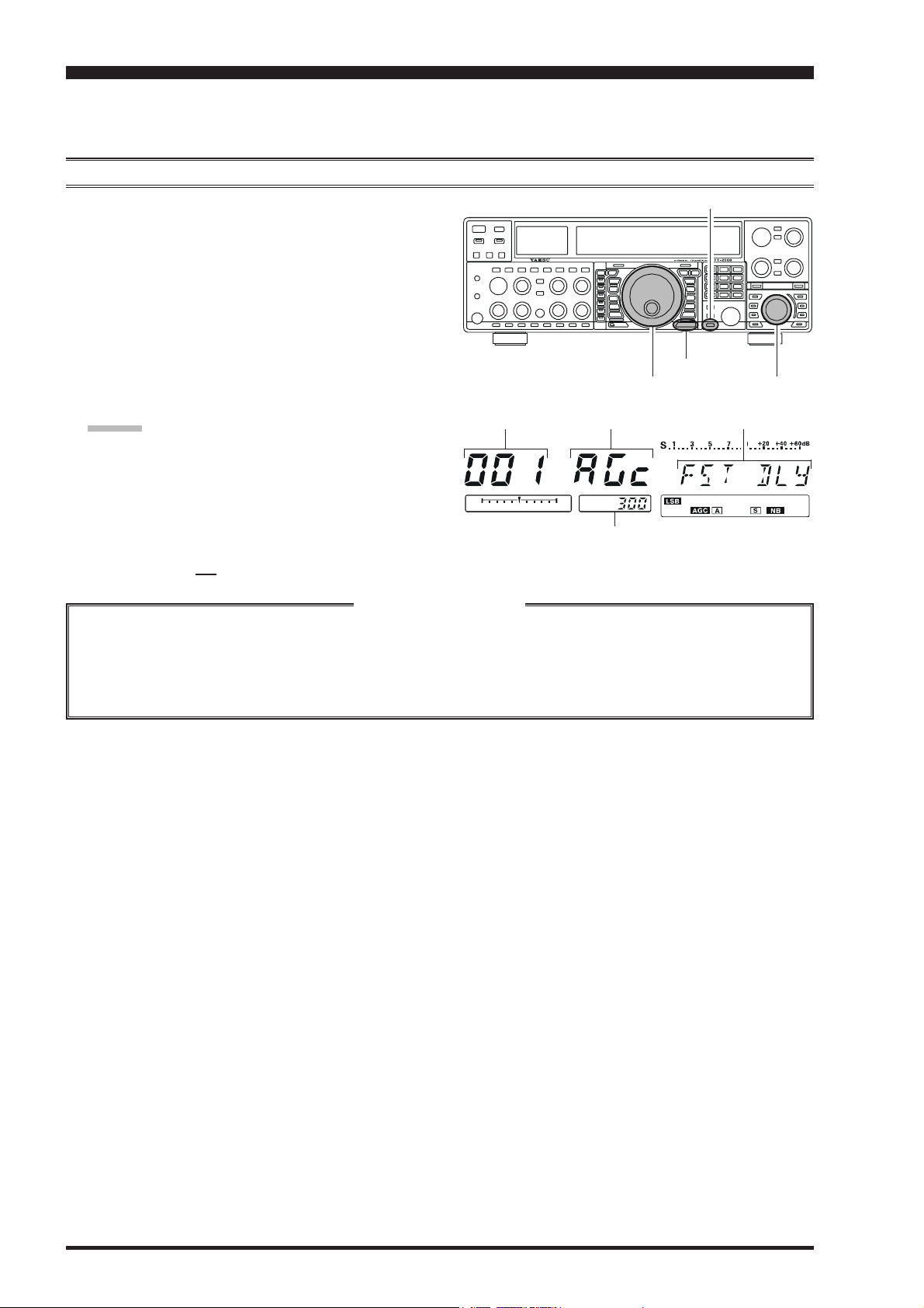
1. Press the [MENU] button momentarily, to engage the
Menu mode.
The Main (VFO-A) frequency display will show the
Menu Number and Menu Group name, while the Sub
(VFO-B) frequency display will show the Menu item;
the Multi-Display window shows the current setting of
the currently-selected Menu item.
2. Rotate the Main Tuning Dial knob to select the Menu
item you wish to work on.
3. Rotate the [SUB VFO-B] knob to change the current
setting of the selected Menu item.
ADVICE:
Press the [CLEAR] button momentarily to reset the
selected Menu item to the factory default value.
4. When you have finished making your adjustments,
press and hold in the [MENU] button for two seconds
to save the new setting and exit to normal operation. If
you only momentarily press the [MENU] button, the
new settings will not be retained.
Main Tuning Dial Knob[SUB VFO-B] Knob
Menu Number Menu Group Name Menu Item
Menu Setting
CLEAR] Button
[
MENU] Button
001 AGc001 AGc
001 AGc
001 AGc001 AGc
Menu Mode Reset
You may reset all the Menu settings to their original factory defaults, if desired.
1. Turn the front panel [POWER] switch off.
2. Press and hold in the [MENU] button, and while holding it in, press the [POWER] switch to turn the transceiver
back on. Now release the [MENU] button.
Page 112 FT-2000D OPERATING MANUAL
Page 2

MENU MODE
GROUP NO. MENU FUNCTION AVAILABLE VALUES DEFAULT SETTING
AGC 001 AGc FST DLY 20 ~ 4000 msec (20 msec/step) 300 msec
AGC 002 AGc FST HLD 0 ~ 2000 msec (20 msec/step) 20 msec
AGC 003 AGc MID DLY 20 ~ 4000 msec (20 msec/step) 700 msec
AGC 004 AGc MID HLD 0 ~ 2000 msec (20 msec/step) 20 msec
AGC 005 AGc SLW DLY 20 ~ 4000 msec (20 msec/step) 2000 msec
AGC 006 AGc SLW HLD 0 ~ 2000 msec (20 msec/step) 20 msec
DISPLAY 007 diSP COLOR bL1 / bL2 / bL3 / ub1 / ub2 bL1
DISPLAY 008 diSP DIM MTR 0 ~ 15 7
DISPLAY 009 diSP DIM VFD 0 ~ 7 4
DISPLAY 010 diSP BAR SEL CLAr / C-tn / u-tn C-tn
DISPLAY 011 diSP PK HLD OFF / 0.5 / 1.0 / 2.0 sec OFF
DISPLAY 012 diSP RTR STU 0 / 90 / 180 / 270° 0°
DISPLAY 013 diSP RTR ADJ –30° ~ 0° (2°/step) 0°
DISPLAY 014 diSP QMB MKR On / OFF On
DISPLAY 015 diSP LVL IND PI / SP / CO / nO / dn / Cd / Ud / rP / nG / Pr / ––
SH / UI
DVS 016 dUS RX LVL 0 ~ 100 50
DVS 017 dUS TX LVL 0 ~ 100 50
KEYER 018 tEy BEACON OFF / 1 ~ 255 sec OFF
KEYER 019 tEy NUM STL 1290 / AunO / Aunt / A2nO / A2nt / 12nO / 12nt 1290
KEYER 020 tEy CONTEST 1 ~ 9999 1
KEYER 021 tEy CW MEM1 tyP1 / tyP2 tyP2
KEYER 022 tEy CW MEM2 tyP1 / tyP2 tyP2
KEYER 023 tEy CW MEM3 tyP1 / tyP2 tyP2
KEYER 024 tEy CW MEM4 tyP1 / tyP2 tyP2
KEYER 025 tEy CW MEM5 tyP1 / tyP2 tyP2
GENERAL 026 GEnE ANT SEL bAnd / rEG bAnd
GENERAL 027 GEnE BEP LVL 0 ~ 100 50
GENERAL 028 GEnE CAT BPS 4800 / 9600 / 192H (19200) / 384H (38400) bps 4800 bps
GENERAL 029 GEnE CAT TOT 10 / 100 / 1000 / 3000 msec 10 msec
GENERAL 030 GEnE CAT RTS On / OFF On
GENERAL 031 GEnE CAT IND On / OFF On
GENERAL 032 GEnE MEM GRP On / OFF OFF
GENERAL 033 GEnE Q SPLIT –20 ~ 0 ~ +20 kHz (1 kHz/step) +5 kHz
GENERAL 034 GEnE TRACK OFF / bAnd / FrEq OFF
GENERAL 035 GEnE TX TOT OFF / 3 / 5 / 10 / 15 / 20 / 30 min OFF
GENERAL 036 GEnE TRV SET 30 ~ 49 MHz 44 MHz
GENERAL 037 GEnE μT DIAL StP1 / StP2 / OFF StP1
GENERAL 038 GEnE SNB LVL nAin (MAIN) / 0~100 nAin(MAIN)
GENERAL 039 GEnE SUB FIL 1200 / 500 / 300 Hz 1200 Hz
GENERAL 040 GEnE MIC SCN On / OFF On
GENERAL 041 GEnE SCN RSM CAr / 5Sec 5SEc
GENERAL 042 GEnE ANTIVOX 0 ~ 100 50
GENERAL 043 GEnE FRQ ADJ –25 ~ 0 ~ +25 0
S IF SFT 044 S-iF LSB SFT –1000 ~ +1000 Hz (20 Hz/step) 0 Hz
S IF SFT 045 S-iF USB SFT –1000 ~ +1000 Hz (20 Hz/step) 0 Hz
S IF SFT 046 S-iF CWL SFT –1000 ~ +1000 Hz (20 Hz/step) 0 Hz
S IF SFT 047 S-iF CWU SFT –1000 ~ +1000 Hz (20 Hz/step) 0 Hz
S IF SFT 048 S-iF RTTY –1000 ~ +1000 Hz (20 Hz/step) 0 Hz
S IF SFT 049 S-iF RTTY-R –1000 ~ +1000 Hz (20 Hz/step) 0 Hz
S IF SFT 050 S-iF PKT-LSB –1000 ~ +1000 Hz (20 Hz/step) 0 Hz
S IF SFT 051 S-iF PKT-USB –1000 ~ +1000 Hz (20 Hz/step) 0 Hz
MODE-AM 052 A3E MICGAIN Ur (VR) / 0 ~ 100 30
MODE-AM 053 A3E MIC SEL Frnt / dAtA / PC Frnt
Ú: Requires optional DMU-2000 Data Management Unit.
Ú
Ú
Ú
Page 113FT-2000D OPERATING MANUAL
Page 3

MENU MODE
GROUP NO. MENU FUNCTION AVAILABLE VALUES DEFAULT SETTING
MODE-CW 054 A1A F-TYPE OFF / buG / ELE / ACS ELE
MODE-CW 055 A1A F-REV nor / rEU (REV) nor
MODE-CW 056 A1A R-TYPE OFF / buG / ELE / ACS ELE
MODE-CW 057 A1A R-REV nor / rEU (REV) nor
MODE-CW 058 A1A CW AUTO OFF / 50 / On OFF
MODE-CW 059 A1A BFO USb / LSb / Auto USb
MODE-CW 060 A1A BK-IN SEni (SEMI) / FuLL SEni (SEMI)
MODE-CW 061 A1A SHAPE 1 / 2 / 4 / 6 msec 4 msec
MODE-CW 062 A1A WEIGHT (1:) 2.5 ~ 4.5 3.0
MODE-CW 063 A1A FRQDISP dir / OFSt OFSt
MODE-CW 064 A1A PC KYNG EnA (Enable) / diS (Disable) diS (Disable)
MODE-CW 065 A1A QSKTIME 15 / 20 / 25 / 30 msec 15 msec
MODE-DAT 066 dAtA DATA IN dAtA / PC dAtA
MODE-DAT 067 dAtA DT GAIN 0 ~ 100 50
MODE-DAT 068 dAtA DT OUT nAin (Main) / Sub nAin (Main)
MODE-DAT 069 dAtA OUT LVL 0 ~ 100 50
MODE-DAT 070 dAtA VOX DLY 30 ~ 3000 msec 300 msec
MODE-DAT 071 dAtA V GAIN 0 ~ 100 50
MODE-DAT 072 dAtA PKTDISP –3000 ~ +3000 Hz (10 Hz/step) 0 Hz
MODE-DAT 073 dAtA PKT SFT –3000 ~ +3000 Hz (10 Hz/step) 1000 Hz
MODE-FM 074 F3E MICGAIN Ur (VR) / 0 ~ 100 50
MODE-FM 075 F3E MIC SEL Frnt / dAtA / PC Frnt
MODE-FM 076 F3E 28 RPT 0 ~ 1000 kHz (10 kHz/step) 100 kHz
MODE-FM 077 F3E 50 RPT 0 ~ 4000 kHz (10 kHz/step) 1000 kHz
MODE-RTY 078 rtty R PLRTY nor / rEU (REV) nor
MODE-RTY 079 rtty T PLRTY nor / rEU (REV) nor
MODE-RTY 080 rtty RTY OUT nAin (Main) / Sub nAin (Main)
MODE-RTY 081 rtty OUT LEL 0 ~ 100 50
MODE-RTY 082 rtty SHIFT 170 / 200 / 425 / 850 Hz 170 Hz
MODE-RTY 083 rtty TONE 1275 / 2125 Hz 2125 Hz
MODE-SSB 084 J3E MIC SEL Frnt / dAtA / PC Frnt
MODE-SSB 085 J3E TX BPF 1-30 / 1-29 / 2-28 / 3-27 / 4-26 / 3000 3-27
MODE-SSB 086 J3E LSB CAR –200 Hz ~ +200 Hz (10 Hz/step) 0 Hz
MODE-SSB 087 J3E USB CAR –200 Hz ~ +200 Hz (10 Hz/step) 0 Hz
MODE-SSB 088 J3E SLSB CR –200 Hz ~ +200 Hz (10 Hz/step) 0 Hz
MODE-SSB 089 J3E SUSB CR –200 Hz ~ +200 Hz (10 Hz/step) 0 Hz
RX AUDIO 090 rout AGC SLP nor / SLP nor
RX AUDIO 091 rout HEADPHN SEP / Con1 / Con2 SEP
RX DSP 092 rdSP CNTR LV –40 ~ +20 dB –15 dB
RX DSP 093 rdSP CNTR WI 1 – 11 10
RX DSP 094 rdSP NOTCH W nArr (Narrow) / uuid (Wide) uuid (Wide)
RX DSP 095 rdSP CW SHAP SOFt / ShAP ShAP
RX DSP 096 rdSP CW SLP StP(STEEP) / nEd(MEDIUM) / GEnt(GENTLE) nEd (MEDIUM)
RX DSP 097 rdSP CW NARR 25 / 50 / 100 / 200 / 300 / 400 / 500 / 800 / 500 Hz
1200 / 1400 / 1700 / 2000 Hz
RX DSP 098 rdSP PKT SHP SOFt / ShAP ShAP
RX DSP 099 rdSP PKT SLP StP(STEEP) / nEd(MEDIUM) / GEnt(GENTLE) nEd (MEDIUM)
RX DSP 100 rdSP PKT NAR 25 / 50 / 100 / 200 / 300 / 400 Hz 300 Hz
RX DSP 101 rdSP RTY SHP SOFt / ShAP ShAP
RX DSP 102 rdSP RTY SLP StP(STEEP) / nEd(MEDIUM) / GEnt(GENTLE) nEd (MEDIUM)
RX DSP 103 rdSP RTY NAR 25 / 50 / 100 / 200 / 300 / 400 Hz 300 Hz
RX DSP 104 rdSP SSB SHP SOFt / ShAP ShAP
RX DSP 105 rdSP SSB SLP StP(STEEP) / nEd(MEDIUM) / GEnt(GENTLE) nEd (MEDIUM)
RX DSP 106 rdSP SSB NAR 200 / 400 / 600 / 850 / 1100 / 1350 / 1500 / 1800 Hz
1650 / 1800 / 1950 / 2100 / 2250 Hz
Page 114 FT-2000D OPERATING MANUAL
Page 4

MENU MODE
GROUP NO. MENU FUNCTION AVAILABLE VALUES DEFAULT SETTING
SCOPE 107 SCP 1.8 FIX 1.800 - 1.999 MHz (1 kHz/step) 1.800 MHz
SCOPE 108 SCP 3.5 FIX 3.500 - 3.999 MHz (1 kHz/step) 3.500 MHz
SCOPE 109 SCP 5.0 FIX 5.250 - 5.499 MHz (1 kHz/step) 5.250 MHz
SCOPE 110 SCP 7.0 FIX 7.000 - 7.299 MHz (1 kHz/step) 7.000 MHz
SCOPE 111 SCP 10.1 FIX (1)0.100 - (1)0.149 MHz (1 kHz/step) (1)0.100 MHz
SCOPE 112 SCP 14.0 FIX (1)4.000 - (1)4.349 MHz (1 kHz/step) (1)4.000 MHz
SCOPE 113 SCP 18.0 FIX (1)8.000 - (1)8.199 MHz (1 kHz/step) (1)8.068 MHz
SCOPE 114 SCP 21.0 FIX (2)1.000 - (2)1.449 MHz (1 kHz/step) (2)1.000 MHz
SCOPE 115 SCP 24.8 FIX (2)4.800 - (2)4.989 MHz (1 kHz/step) (2)4.890 MHz
SCOPE 116 SCP 28.0 FIX (2)8.000 - (2)9.699 MHz (1 kHz/step) (2)8.000 MHz
SCOPE 117 SCP 50.0 FIX (5)0.000 - (5)3.999 MHz (1 kHz/step) (5)0.000 MHz
TUNING 118 tun DIALSTP 1 / 5 / 10 Hz 10 Hz
TUNING 119 tun CW FINE EnA / diS diS
TUNING 120 tun MHz SEL 1 / 0.1 MHz 1 MHz
TUNING 121 tun AM STEP 2.5 / 5 / 9 / 10 / 12.5 kHz 5 kHz
TUNING 122 tun FM STEP 5 / 6.25 / 10 / 12.5 / 20 / 25 kHz 5 kHz
TUNING 123 tun FM DIAL 10 / 100 Hz 100 Hz
TUNING 124 tun MY BAND 1.8 ~ 50 / GE / AU ––
TX AUDIO 125 tAUd EQ1 FRQ OFF / 100 ~ 700 Hz (100 Hz/step) OFF
TX AUDIO 126 tAUd EQ1 LVL –20 ~ +10 +5
TX AUDIO 127 tAUd EQ1 BW 1 ~ 10 10
TX AUDIO 128 tAUd EQ2 FRQ OFF / 700 ~ 1500 Hz (100 Hz/step) OFF
TX AUDIO 129 tAUd EQ2 LVL –20 ~ +10 +5
TX AUDIO 130 tAUd EQ2 BW 1 ~ 10 10
TX AUDIO 131 tAUd EQ3 FRQ OFF / 1500 ~ 3200 Hz (100 Hz/step) OFF
TX AUDIO 132 tAUd EQ3 LVL –20 ~ +10 +5
TX AUDIO 133 tAUd EQ3 BW 1 ~ 10 10
TX AUDIO 134 tAUd PE1 FRQ OFF / 100 ~ 700 Hz (100 Hz/step) 200
TX AUDIO 135 tAUd PE1 LVL –20 ~ +10 0
TX AUDIO 136 tAUd PE1 BW 1 ~ 10 2
TX AUDIO 137 tAUd PE2 FRQ OFF / 700 ~ 1500 Hz (100 Hz/step) 800
TX AUDIO 138 tAUd PE2 LVL –20 ~ +10 0
TX AUDIO 139 tAUd PE2 BW 1 ~ 10 1
TX AUDIO 140 tAUd PE3 FRQ OFF / 1500 ~ 3200 Hz (100 Hz/step) 2100 Hz
TX AUDIO 141 tAUd PE3 LVL –20 ~ +10 0
TX AUDIO 142 tAUd PE3 BW 1 ~ 10 1
TX GNRL 143 tGEn BIAS Ab / 0 ~ 100 Ab
TX GNRL 144 tGEn MAX PWR 20 / 50 / 100 / 200 W 200 W
TX GNRL 145 tGEn PWRCTRL ALL / Car ALL
TX GNRL 146 tGEn ETX-GND EnA (ENABLE) / diS (DISABLE) diS (DISABLE)
TX GNRL 147 tGEn TUN PWR 20 / 50 / 100 / 200 W 100 W
TX GNRL 148 tGEn VOX SEL nic (MIC) / dAtA nic (MIC)
TX GNRL 149 tGEn EMRGNCY EnA (ENABLE) / diS (DISABLE) diS (DISABLE)
Ú: Requires optional DMU-2000 Data Management Unit.
Ú
Ú
Ú
Ú
Ú
Ú
Ú
Ú
Ú
Ú
Ú
Page 115FT-2000D OPERATING MANUAL
Page 5

MENU MODE
AGC GROUP
001 AGc FST DLY
Function: Sets the delay time for the AGC FAST mode of
the Main band (VFO-A) receiver.
Available Values: 20 ~ 4000 msec (20 msec/step)
Default Setting: 300 msec
002 AGc FST HLD
Function: Sets the hang time of the AGC peak voltage for
the AGC FAST mode of the Main band (VFO-A) receiver.
Available Values: 0 ~ 2000 msec (20 msec/step)
Default Setting: 20 msec
003 AGc MID DLY
Function: Sets the delay time for the AGC MID mode of
the Main band (VFO-A) receiver.
Available Values: 20 ~ 4000 msec (20 msec/step)
Default Setting: 700 msec
004 AGc MID HLD
Function: Sets the hang time of the AGC peak voltage for
the AGC MID mode of the Main band (VFO-A) receiver.
Available Values: 0 ~ 2000 msec (20 msec/step)
Default Setting: 20 msec
005 AGc SLW DLY
Function: Sets the delay time for the AGC SLOW mode of
the Main band (VFO-A) receiver.
Available Values: 20 ~ 4000 msec (20 msec/step)
Default Setting: 2000 msec
006 AGc SLW HLD
Function: Sets the hang time of the AGC peak voltage for
the AGC SLOW mode of the Main band (VFO-A) receiver.
Available Values: 0 ~ 2000 msec (20 msec/step)
Default Setting: 20 msec
DISPLAY GROUP
007 diSP COLOR
Function: Selects the Display color when the optional Data
Management Unit (DMU-2000) is connected.
Available Values: bL1 / bL2 / bL3 / ub1 / ub2
bL1: COOL BLUE
bL2: CONTRAST BLUE
bL3: FLASH WHITE
ub1: CONTRAST UMBER
ub2: UMBER
Default Setting: bL1 (COOL BLUE)
ADVICE:
If the optional DMU-2000 Data Management Unit is not
connected, this adjustment has no effect.
008 diSP DIM MTR
Function: Setting of the meter brightness level when
“DIM” is selected.
Available Values: 0 ~ 15
Default Setting: 7
009 diSP DIM VFD
Function: Setting of the frequency display brightness level
when “DIM” is selected.
Available Values: 0 ~ 7
Default Setting: 4
010 diSP BAR SEL
Function: Selects one of three parameters to be viewed
on the Tuning Offset Indicator.
Available Values: CLAr / C-tn / u-tn
Default Setting: C-tn
CLAr: Displays relative clarifier offset.
C-tu: Displays relative CW tuning offset between the
incoming signal and transmitted frequency.
u-tn: Displays the peak position of the VRF or μ-
TUNE filter.
NOTE:
The μ-TUNE filter is an option.
011 diSP PK HLD
Function: Selects the peak hold time of the Sub (VFO-B)
receiver’s S-meter.
Available Values: OFF / 0.5 / 1.0 / 2.0 sec
Default Setting: OFF
012 diSP RTR STU
Function: Selects the starting point of your rotator
controller’s indicator needle.
Available Values: 0 / 90 / 180 / 270°
Default Setting: 0°
013 diSP RTR ADJ
Function: Adjusts the indicator needle precisely to the
starting point set in menu item “012 diSP RTR STU.”
Available Values: –30 ~ 0°
Default Setting: 0°
Page 116 FT-2000D OPERATING MANUAL
Page 6

MENU MODE
DISPLAY GROUP KEYER GROUP
014 diSP QMB MKR
Function: Enables/Disables the QMB Marker (White arrow “V”) to display on the Spectrum Band Scope when
the optional DMU-2000 Data Management Unit is connected.
Available Values: On / OFF
Default Setting: On
ADVICE:
If the optional DMU-2000 Data Management Unit is not
connected, this adjustment has no effect.
015 diSP LVL IND
Function: Enables/Disables the Sub band (VFO-B) frequency display to show each frequency or value while each
of the enabled knob is turned.
Available Values: PI (PITCH) / SP (SPEED) / CO (CONTOUR) / nO (NOTCH) / dn (DNR) / Cd (CW DELAY) /
Ud (VOX DEALAY) / rP (RF POWER) / nG (MIC GAIN) /
Pr (PROCESSOR GAIN) / SH (IF SHIFT) / UI (IF
WIDTH)
To disable the “function,” rotate the [SUB VFO-B] knob
to recall the “function” to be disabled, then press the [ENT
key to change this setting to “OFF” (a “
replace the “
enable a function (setting it to “ON” (“
pears)”).
dd
d” notation). Repeat the same procedures to
dd
EE
E” notation will
EE
EE
E” notation ap-
EE
DVS GROUP
016 dUS RX LVL
Function: Sets the audio output level from the voice
memory.
Available Values: 0 ~ 100
Default: 50
017 dUS TX LVL
Function: Sets the microphone input level to the voice
memory
Available Values: 0 ~ 100
Default: 50
018 tEy BEACON
Function: Sets the interval time between repeats of the
beacon message.
Available Values: OFF / 1 ~ 255 sec
Default Setting: OFF
019 tEy NUM STL
Function: Selects the Contest Number “Cut” format for
an imbedded contest number.
Available Values: 1290 / AunO / Aunt / A2nO / A2nt /
12nO / 12nt
Default Setting: 1290
1290: Does not abbreviate the Contest Number
AunO: Abbreviates to “A” for “One,” “U” for “Two,”
“N” for “Nine,” and “O” for “Zero.”
Aunt: Abbreviates to “A” for “One,” “U” for “Two,”
“N” for “Nine,” and “T” for “Zero.”
A2nO: Abbreviates to “A” for “One,” “N” for “Nine,”
and “O” for “Zero.”
A2nt: Abbreviates to “A” for “One,” “N” for “Nine,”
]
and “T” for “Zero.”
12nO: Abbreviates to “N” for “Nine,” and “O” for
“Zero.”
12nt: Abbreviates to “N” for “Nine,” and “T” for
“Zero.”
020 tEy CONTEST
Function: Enters the initial contest number that will increment/decrement after sending during contest QSOs.
Available Values: 1 ~ 9999
Default Setting: 1
ADVICE:
Press the [CLEAR] button to reset the contest number to
“1.”
021 tEy CW MEM1
Function: Permits entry of the CW message for message
register 1.
Available Values: tyP1 / tyP2
Default Setting: tyP2
tyP1: You may enter the CW message from the front
panel’s Function Keys.
tyP2: You may enter the CW message from the CW
keyer.
022 tEy CW MEM2
Function: Permits entry of the CW message for message
register 2.
Available Values: tyP1 / tyP2
Default Setting: tyP2
tyP1: You may enter the CW message from the front
panel’s Function Keys.
tyP2: You may enter the CW message from the CW
keyer.
Page 117FT-2000D OPERATING MANUAL
Page 7

MENU MODE
KEYER GROUP
023 tEy CW MEM3
Function: Permits entry of the CW message for message
register 3.
Available Values: tyP1 / tyP2
Default Setting: tyP2
tyP1: You may enter the CW message from the front
panel’s Function Keys.
tyP2: You may enter the CW message from the CW
keyer.
024 tEy CW MEM4
Function: Permits entry of the CW message for message
register 4.
Available Values: tyP1 / tyP2
Default Setting: tyP2
tyP1: You may enter the CW message from the front
panel’s Function Keys.
tyP2: You may enter the CW message from the CW
keyer.
025 tEy CW MEM5
Function: Permits entry of the CW message for message
register 5.
Available Values: tyP1 / tyP2
Default Setting: tyP2
tyP1: You may enter the CW message from the front
panel’s Function Keys.
tyP2: You may enter the CW message from the CW
keyer.
ADVICE:
If the optional FH-2 Remote Control Keypad is not connected, this adjustment has no effect.
GENERAL GROUP
026 GEnE ANT SEL
Function: Sets the method of antenna selection.
Available Values: bAnd / rEG
Default Setting: bAnd
bAnd:The antenna is selected in accordance with the
operating band.
rEG: The antenna is selected in accordance with the
band stack (different antennas may be utilized
on the same band, if so selected in the band
stack).
027 GEnE BEP LVL
Function: Sets the beep level.
Available Values: 0 ~ 100
Default Setting: 50
028 GEnE CAT BPS
Function: Sets the transceiver’s computer-interface circuitry for the CAT baud rate to be used.
Available Values: 4800 / 9600 / 192H(19200) /
384H (38400) bps
Default Setting: 4800 bps
029 GEnE CAT TOT
Function: Sets the Time-Out Timer countdown time for a
CAT command input.
Available Values: 10 / 100 / 1000 / 3000 msec
Default Setting: 10 msec
The Time-Out Timer shuts off the CAT data input after the
continuous transmission of the programmed time.
030 GEnE CAT RTS
Function: Enables/Disables the RTS port of the CAT jack.
Available Values: On/OFF
Default Setting: On
031 GEnE CAT IND
Function: Enables/Disables the flashing of the Data LED
inside the [CS] switch in conjunction with the CAT commands.
Available Values: On / OFF
Default Setting: On
032 GEnE MEM GRP
Function: Enables/Disables Memory Group Operation.
Available Values: On / OFF
Default Setting: OFF
033 GEnE Q SPLIT
Function: Selects the tuning offset for the Quick Split feature.
Available Values: –20 ~ 0 ~ +20 kHz (1 kHz Step)
Default Setting: +5 kHz
Page 118 FT-2000D OPERATING MANUAL
Page 8

GENERAL GROUP
MENU MODE
034 GEnE TRACK
Function: Sets the VFO Tracking feature.
Available Values: OFF / bAND / FrEq
Default Setting: OFF
OFF: Disables the VFO Tracking feature.
bAND: When you change bands on the Main (VFO-
A) side, the Sub (VFO-B) band’s VFO will
automatically change to be the same as that of
VFO-A.
FrEq: This function is the almost same as “bAND,”
however, furthermore, the Sub band’s (VFOB) frequency changes together with the Main
Band’s (VFO-A) frequency when turning the
Main Dial Tuning knob.
035 GEnE TX TOT
Function: Sets the Time-Out Timer countdown time.
Available Values: OFF / 3 / 5 / 10 / 15 / 20 / 30 min
Default Setting: OFF
The Time-Out Timer shuts off the transmitter after continuous transmission of the programmed time.
036 GEnE TRV SET
Function: Sets the 10’s and 1’s of the MHz digits display
for operation with a transverter.
Available Values: 30 ~ 49 MHz
Default Setting: 44 MHz
The default setting would be used with a 144 MHz
transverter. If you connect a 430 MHz transverter to the
radio, set this menu to “30” (the “100 MHz” digits are
hidden on this radio).
037 GEnE μT DIAL
Function: Selects the μ-TUNE mode.
Available Values: StP1 / StP2 / OFF
Default Setting: StP1
StP1: Activates the μ-TUNE system using
“COARSE” steps of the [VRF] knob (2 steps/
click) on the 7 MHz and lower amateur bands.
On the 10/14 MHz bands, “FINE” [VRF] knob
steps (1 step/click) will be used.
StP2: Activates the μ-TUNE system using “FINE”
steps of the [VRF] knob (1 step/click) on the
14 MHz and lower amateur bands on the Main
band (VFO-A).
OFF: Disables the μ-TUNE system. Activates the
VRF feature on the 14 MHz and lower amateur
bands on the main band (VFO-A).
ADVICE:
If the optional RF μTuning Kit is not connected, this adjustment has no effect.
038 GEnE SNB LVL
Function: Adjusts the Sub band (VFO-B) receiver’s IF
Noise Blanker level, when the Noise Blanker is engaged.
Available Values: nAin(MAIN) / 0~100
Default Setting: nAin(MAIN)
When this menu is set to “nAin(MAIN),” you may adjust
the Noise Blanker level using the front panel’s [NB] knob.
039 GEnE SUB FIL
Function: Defines the Sub band (VFO-B) receiver’s CW
narrow filter.
Available Values: 1200 / 500 / 300 Hz
Default Setting: 1200 Hz
ADVICE:
This Menu item tells the microprocessor which (if any)
optional filter has been installed.
040 GEnE MIC SCN
Function: Enables/disables scanning access via the
microphone’s [UP]/[DWN] keys.
Available Values: On / OFF
Default Setting: On
041 GEnE SCN RSM
Function: Selects the Scan Resume mode.
Available Values: CAr / 5SEc
Default Setting: 5SEc
CAr: The scanner will hold until the signal disappears,
then will resume after one second.
5SEc: The scanner will hold for five seconds, then re-
sume whether or not the other station is still
transmitting.
042 GEnE ANTIVOX
Function: Adjusts the Anti-VOX Trip Gain which is the
level of negative feedback of receiver audio to the microphone, to prevent receiver audio from activating the transmitter (via the microphone) during VOX operation.
Available Values: 0 ~ 100
Default Setting: 50
043 GEnE FRQ ADJ
Function: Adjusts the reference oscillator.
Available Values: –25 ~ 0 ~ +25
Default Setting: 0
Connect a 50-Ohm dummy load and frequency counter to
the antenna jack; adjust the [SUB VFO-B] knob so that
the frequency counter reading is same as the VFO frequency while pressing the PTT switch.
ADVICE:
Do not perform this Menu item unless you have a highperformance frequency counter. Perform this Menu item
after aging the transceiver and frequency counter sufficiently (at least 30 minutes).
Page 119FT-2000D OPERATING MANUAL
Page 9

MENU MODE
S IF SFT
(
S
UB BAND IF SHIFT
)
GROUP
044 S-iF LSB SFT
Function: Sets the center frequency of the Sub band (VFOB) receiver’s IF filter in the LSB mode.
Available Values: –1000 ~ +1000 Hz (20Hz/step)
Default Setting: 0 Hz
045 S-iF USB SFT
Function: Sets the center frequency of the Sub band (VFOB) receiver’s IF filter in the USB mode.
Available Values: –1000 ~ +1000 Hz (20Hz/step)
Default Setting: 0 Hz
046 S-iF CWL SFT
Function: Sets the center frequency of the Sub band (VFOB) receiver’s IF filter in the CW (LSB) mode.
Available Values: –1000 ~ +1000 Hz (20Hz/step)
Default Setting: 0 Hz
047 S-iF CWU SFT
Function: Sets the center frequency of the Sub band (VFOB) receiver’s IF filter in the CW (USB) mode.
Available Values: –1000 ~ +1000 Hz (20Hz/step)
Default Setting: 0 Hz
MODE-AM GROUP
052 A3E MICGAIN
Function: Sets the microphone gain for the AM mode.
Available Values: Ur (VR) / 0 ~ 100
Default Setting: 30
When this menu is set to “Ur (VR),” you may adjust the
microphone gain using the front panel’s [MIC] knob.
053 A3E MIC SEL
Function: Selects the microphone to be used on the AM
mode.
Available Values: Frnt / dAtA / PC
Default Setting: Frnt
Frnt: Selects the microphone connected to the front
panel’s MIC jack while using the AM mode.
dAtA: Selects the microphone connected to pin 1 of
the PACKET Jack while using the AM mode.
PC: This parameter is for future expansion of this
transceiver’s capabilities, but at this time is not
supported.
048 S-iF RTTY
Function: Sets the center frequency of the Sub band (VFOB) receiver’s IF filter in the RTTY mode.
Available Values: –1000 ~ +1000 Hz (20Hz/step)
Default Setting: 0 Hz
049 S-iF RTTY-R
Function: Sets the center frequency of the Sub band (VFOB) receiver’s IF filter in the RTTY reverse mode.
Available Values: –1000 ~ +1000 Hz (20Hz/step)
Default Setting: 0 Hz
050 S-iF PKT-LSB
Function: Sets the center frequency of the Sub band (VFOB) receiver’s IF filter in the Packet (LSB) mode.
Available Values: –1000 ~ +1000 Hz (20Hz/step)
Default Setting: 0 Hz
051 S-iF PKT-USB
Function: Sets the center frequency of the Sub band (VFOB) receiver’s IF filter in the Packet (USB) mode.
Available Values: –1000 ~ +1000 Hz (20Hz/step)
Default Setting: 0 Hz
Page 120 FT-2000D OPERATING MANUAL
Page 10

MODE-CW GROUP
MENU MODE
054 A1A F-TYPE
Function: Selects the desired keyer operation mode for
the device connected to the front panel’s KEY jack.
Available Values: OFF / buG / ELE / ACS
Default Setting: ELE
OFF: Disables the front panel’s keyer (“straight key”
mode for use with external keyer or computerdriven keying interface).
buG: Mechanical “bug” keyer emulation. One paddle
produces “dits” automatically, while the other
paddle manually produces “dahs.”
ELE: Iambic keyer with ACS (Automatic Character
Spacing) disabled.
ACS: Iambic keyer with ACS (Automatic Character
Spacing) enabled.
055 A1A F-REV
Function: Selects the keyer paddle’s wiring configuration
for the KEY jack on the front panel.
Available Values: nor / rEU (REV)
Default Setting: nor
nor: Tip = Dot, Ring = Dash, Shaft = Ground
rEU (REV): Tip = Dash, Ring = Dot, Shaft = Ground
056 A1A R-TYPE
Function: Selects the desired keyer operation mode for
the device connected to the rear panel’s KEY jack.
Available Values: OFF / buG / ELE / ACS
Default Setting: ELE
OFF: Disables the rear panel’s keyer (“straight key”
mode for use with external keyer or computerdriven keying interface).
buG: Mechanical “bug” keyer emulation. One paddle
produces “dits” automatically, while the other
paddle manually produces “dahs.”
ELE: Iambic keyer with ACS (Automatic Character
Spacing) disabled.
ACS: Iambic keyer with ACS (Automatic Character
Spacing) enabled.
057 A1A R-REV
Function: Selects the keyer paddle’s wiring configuration
for the KEY jack on the rear panel.
Available Values: nor / rEU (REV)
Default Setting: nor
nor: Tip = Dot, Ring = Dash, Shaft = Ground
rEU (REV): Tip = Dash, Ring = Dot, Shaft = Ground
058 A1A CW AUTO
Function: Enables/disables CW keying while operating
on SSB.
Available Values: OFF / 50 / On
Default Setting: OFF
OFF: Disables CW keying while operating on SSB.
50: Enables CW keying only while operating SSB
on 50 MHz (but not HF).
On: Enables CW keying while operating on SSB (all
TX bands).
NOTE:
This feature allows you to move someone from SSB to
CW without having to change modes on the front panel.
059 A1A BFO
Function: Sets the CW carrier oscillator injection side for
the CW mode.
Available Values: USb / LSb / Auto
Default Setting: USb
USb: Injects the CW carrier oscillator on the USB side.
LSb: Injects the CW carrier oscillator on the LSB side.
Auto: Injects the CW carrier oscillator on the LSB side
while operating on the 7 MHz band and below,
and the USB side while operating on the 10 MHz
band and up.
060 A1A BK-IN
Function: Sets the CW “break-in” mode.
Available Values: SEni / FuLL
Default Setting: SEni
SEni (SEMI): The transceiver will operate in the semi
break-in mode. The delay (receiver recovery) time is set by the front panel’s
[
DELAY] knob.
FuLL: The transceiver will operate in the full
break-in (QSK) mode.
061 A1A SHAPE
Function: Selects the CW carrier wave-form shape (rise/
fall times).
Available Values: 1 / 2 / 4 / 6 msec
Default Setting: 4 msec
062 A1A WEIGHT
Function: Sets the Dot:Dash ratio for the built-in electronic keyer.
Available Values: (1:) 2.5 ~ 4.5
Default Setting: 3.0
Page 121FT-2000D OPERATING MANUAL
Page 11

MENU MODE
MODE-CW GROUP
063 A1A FRQDISP
Function: Selects the frequency Display Format for the
CW mode.
Available Values: dir / OFSt
Default Setting: OFSt
dir (Direct Frequency): Displays the receiver carrier
frequency, without any offset
added. When changing
modes between SSB and CW,
the frequency display remains constant.
OFSt (Pitch Offset): This frequency display re-
flects the added BFO offset.
064 A1A PC KYNG
Function: Enables/disables CW keying from the
“PACKET PTT” terminal (pin 3) on the rear panel’s
PACKET jack while operating on the CW mode.
Available Values: EnA (Enable) / diS (Disable)
Default Setting: diS (Disable)
065 A1A QSKTIME
Function: Selects the time delay between when the PTT
is keyed and the carrier is transmitted during QSK operation when using the internal keyer.
Available Values: 15 / 20 / 25 / 30 msec
Default Setting: 15 msec
MODE-DAT GROUP
066 dAtA DATA IN
Function: Selects the data input path to be used on the
PKT mode.
Available Values: dAtA / PC
Default Setting: dAtA
dAtA:Uses the data input line connected to pin 1 of
the PACKET jack while using the PKT mode.
PC: This parameter is for future expansion of this
transceiver’s capabilities, but at this time is not
supported.
067 dAtA DT GAIN
Function: Sets the data input level from the TNC to the
AFSK modulator.
Available Values: 0 ~ 100
Default Setting: 50
068 dAtA DT OUT
Function: Selects the receiver to be connected to the data
output port (pin 4) of the PACKET jack.
Available Values: nAin (Main) / Sub
Default Setting: nAin (Main)
069 dAtA OUT LVL
Function: Sets the AFSK data output level at the output
port (pin 4) of the PACKET jack.
Available Values: 0 ~ 100
Default Setting: 50
070 dAtA VOX DLY
Function: Adjusts the “VOX” delay (receiver recovery)
time on the PKT mode.
Available Values: 30 ~ 3000 msec
Default Setting: 300 msec
071 dAtA V GAIN
Function: Adjusts the “VOX” gain on the PKT mode.
Available Values: 0 ~ 100
Default Setting: 50
072 dAtA PKTDISP
Function: Sets the packet frequency display offset.
Available: –3000 ~ +3000 Hz (10 Hz/step)
Default: 0 Hz
073 dAtA PKT SFT
Function: Sets the carrier point during the SSB packet
operation.
Available: –3000 ~ +3000 Hz (10 Hz/step)
Default: 1000 Hz (typical center frequency for PSK31,
etc.)
Page 122 FT-2000D OPERATING MANUAL
Page 12

MENU MODE
MODE-FM GROUP
074 F3E MICGAIN
Function: Sets the microphone gain for the FM mode.
Available Values: Ur (VR) / 0 ~ 100
Default Setting: 50
When this menu is set to “Ur (VR),” you may adjust the
microphone gain using the front panel’s [MIC] knob.
075 F3E MIC SEL
Function: Selects the microphone to be used on the FM
mode.
Available Values: Frnt / dAtA / PC
Default Setting: Frnt
Frnt (FRONT): Selects the microphone connected to
the front panel’s MIC jack while us-
ing the FM mode.
dAtA: Selects the microphone connected to
pin 1 of the PACKET Jack while us-
ing the FM mode.
PC: This parameter is for future expansion
of this transceiver’s capabilities, but
at this time is not supported.
076 F3E 28 RPT
Function: Sets the magnitude of the repeater shift on the
28 MHz band.
Available Values: 0 ~ 1000 kHz (10 kHz/step)
Default Setting: 100 kHz
077 F3E 50 RPT
Function: Sets the magnitude of the repeater shift on the
50 MHz band.
Available Values: 0 ~ 4000 kHz (10 kHz/step)
Default Setting: 1000 kHz
MODE-RTY GROUP
078 rtty R PLRTY
Function: Selects normal or reverse Mark/Space polarity
for RTTY receive operation.
Available Values: nor / rEU (REV)
Default Setting: nor
079 rtty T PLRTY
Function: Selects normal or reverse Mark/Space polarity
for RTTY transmit operation.
Available Values: nor / rEU (REV)
Default Setting: nor
080 rtty RTY OUT
Function: Selects the receiver to be connected to the data
output port (pin 2) of the RTTY jack.
Available Values: nAin (Main) / Sub
Default Setting: nAin (Main)
081 rtty OUT LEL
Function: Sets the FSK RTTY data output level at the
output port (pin 2) of the RTTY jack.
Available Values: 0 ~ 100
Default Setting: 50
082 rtty SHIFT
Function: Selects the frequency shift for FSK RTTY operation.
Available Values:170 / 200 / 425 / 850 Hz
Default Setting: 170 Hz
083 rtty TONE
Function: Selects the Mark tone for RTTY operation.
Available Values: 1275 / 2125 Hz
Default Setting: 2125 Hz
Page 123FT-2000D OPERATING MANUAL
Page 13

MENU MODE
Aud
O
MODE-SSB GROUP
084 J3E MIC SEL
Function: Selects the microphone to be used on the SSB
modes (LSB and USB).
Available Values: Frnt / dAtA / PC
Default Setting: Frnt
Frnt (FRONT): Selects the microphone connected to
the front panel’s MIC jack while using
the SSB modes.
dAtA: Selects the microphone connected to
pin 1 of the PACKET Jack while us-
ing the SSB modes.
PC: This parameter is for future expansion
of this transceiver’s capabilities, but at
this time is not supported.
085 J3E TX BPF
Function: Selects the audio passband of the DSP modulator on the SSB mode.
Available Values: 1-30 / 1-29 / 2-28 / 3-27 / 4-26 / 3000
1-30: 50-3000(Hz)
1-29: 100-2900(Hz)
2-28: 200-2800(Hz)
3-27: 300-2700(Hz)
4-26: 400-2600(Hz)
3000: 3000WB
Default Setting: 3-27 (300-2700 Hz)
NOTE:
The apparent power output, when using the widest bandwidths, may seem lower. This is normal, and it occurs because the available transmitter power is distributed over a
wider bandwidth. The greatest compression of power output, conversely, occurs when using the “4-26” setting (4002600 Hz), and this setting is highly recommended for contest or DX pile-up work.
086 J3E LSB CAR
Function: Adjusts the receiver carrier point for the Main
band’s (VFO-A) LSB mode.
Available Values: –200 Hz ~ +200 Hz (10 Hz/steps)
Default Setting: 0 Hz
RX AUDIO GROUP
090 rout AGC SLP
Function: Selects the gain curve of the AGC amplifier.
Available Values: nor / SLP
Default Setting: nor
nor (NORMAL): The AGC output level will follow a
linear response to the antenna input
level, while AGC is activated.
SLP (SLOPED): The AGC output level will increase
at 1/10 the rate of the antenna input
level, while AGC is activated.
SLOPE
utput
io
Input Signal
091 rout HEADPHN
Function: Selects one of three audio mixing modes when
using headphones during Dual Receive operation.
Available Values: SEP / Con1 / Con2
Default Setting: SEP
SEP (SEPARATE): Audio from the Main (VFO-A)
receiver is heard only in the left
ear, and Sub (VFO-B) receiver
audio solely in the right ear.
Con1 (COMBINE 1): Audio from both Main (VFO-
A) and Sub (VFO-B) receivers
can be heard in both ears, but
Sub (VFO-B) audio is attenuated in the left ear and Main
(VFO-A) audio is attenuated in
the right ear.
Con2 (COMBINE 2): Audio from both Main (VFO-
A) and Sub (VFO-B) receivers
is combined and heard equally
in both ears.
NORMAL
087 J3E USB CAR
Function: Adjusts the receiver carrier point for Main
band’s (VFO-A) USB mode.
Available Values: –200 Hz ~ +200 Hz (10 Hz/step)
Default Setting: 0 Hz
088 J3E SLSB CR
Function: Adjusts the receiver carrier point for the Sub
band’s (VFO-B) LSB mode.
Available Values: –200 Hz ~ +200 Hz (10 Hz/step)
Default Setting: 0 Hz
089 J3E SUSB CR
Function: Adjusts the receiver carrier point for Sub band’s
(VFO-B) USB mode.
Available Values: –200 Hz ~ +200 Hz (10 Hz/step)
Default Setting: 0 Hz
Page 124 FT-2000D OPERATING MANUAL
Page 14

RX DSP GROUP
MENU MODE
092 rdSP CNTR LV
Function: Adjusts the gain of the Contour filter.
Available Values: –40 ~ +20 dB
Default Setting: –15 dB
093 rdSP CNTR WI
Function: Adjusts the Q-factor of the Contour filter.
Available Values: 1 - 11
Default Setting: 10
“Q”
“+” Gain
“--” Gain
IF
BANDWIDTH
CONTOUR “GAIN” AND “Q”
094 rdSP NOTCH W
Function: Selects the bandwidth of the DSP NOTCH filter
Available Values: nArr (Narrow) / uuid (Wide)
Default Setting: uuid (Wide)
095 rdSP CW SHAP
Function: Selects the passband characteristics of the DSP
filter for the CW mode.
Available Values: SOFt / ShAP
Default Setting: ShAP
SOFt (SOFT): Primary importance is attached to the
phase of the filter factor.
ShAP (SHARP): Primary importance is attached to the
amplitude of the filter factor.
096 rdSP CW SLP
Function: Selects the shape factor of the DSP filter for
the CW mode.
Available Values: StP(STEEP) / nEd(MEDIUM) /
GEnt(GENTLE)
Default Setting: nEd (MEDIUM)
098 rdSP PKT SHP
Function: Selects the passband characteristics of the DSP
filter for the PKT mode.
Available Values: SOFt / ShAP
Default Setting: ShAP
SOFt (SOFT): Primary importance is attached to the
phase of the filter factor.
ShAP (SHARP): Primary importance is attached to the
amplitude of the filter factor.
099 rdSP PKT SLP
Function: Selects the shape factor of the DSP filter for
the PKT mode.
Available Values: StP(STEEP) / nEd(MEDIUM) /
GEnt(GENTLE)
Default Setting: nEd (MEDIUM)
100 rdSP PKT NAR
Function: Selects the passband of the DSP filter for the
PKT “Narrow” mode.
Available Values: 25 / 50 / 100 / 200 / 300 / 400 Hz
Default Setting: 300 Hz
101 rdSP RTY SHP
Function: Selects the passband characteristics of the DSP
filter for the RTTY mode.
Available Values: SOFt / ShAP
Default Setting: ShAP
SOFt (SOFT): Primary importance is attached to the
phase of the filter factor.
ShAP (SHARP): Primary importance is attached to the
amplitude of the filter factor.
102 rdSP RTY SLP
Function: Selects the shape factor of the DSP filter for
the RTTY mode.
Available Values: StP(STEEP) / nEd(MEDIUM) /
GEnt(GENTLE)
Default Setting: nEd (MEDIUM)
103 rdSP RTY NAR
Function: Selects the passband of the DSP filter for the
RTTY “Narrow” mode.
Available Values: 25 / 50 / 100 / 200 / 300 / 400 Hz
Default Setting: 300 Hz
097 rdSP CW NARR
Function: Selects the passband of the DSP filter for the
CW “Narrow” mode.
Available Values: 25 / 50 / 100 / 200 / 300 / 400 / 500 /
800 / 1200 / 1400 / 1700 / 2000 Hz
Default Setting: 500 Hz
Page 125FT-2000D OPERATING MANUAL
Page 15

MENU MODE
RX DSP GROUP
104 rdSP SSB SHP
Function: Selects the passband characteristics of the DSP
filter for the SSB modes (LSB and USB).
Available Values: SOFt / ShAP
Default Setting: ShAP
SOFt (SOFT): Primary importance is attached to the
phase of the filter factor.
ShAP (SHARP): Primary importance is attached to the
amplitude of the filter factor.
105 rdSP SSB SLP
Function: Selects the shape factor of the DSP filter for
the SSB modes (LSB and USB).
Available Values: StP(STEEP) / nEd(MEDIUM) /
GEnt(GENTLE)
Default Setting: nEd (MEDIUM)
106 rdSP SSB NAR
Function: Selects the passband of the DSP filter for the
“Narrow” SSB mode.
Available Values: 200 / 400 / 600 / 850 / 1100 / 1350 /
1500 / 1650 / 1800 / 1950 / 2100 / 2250 Hz
Default Setting: 1800 Hz
SCOPE GROUP
ADVICE:
This group’s adjustment has no effect, if the optional DMU2000 Data Management Unit is not connected.
107 SCP 1.8 FIX
Function: Selects the scan start frequency of the FIX mode
Spectrum Scope while monitoring on the 160 m amateur
band.
Available Values: 1.800 - 1.999 MHz (1 kHz/step)
Default Setting: 1.800 MHz
108 SCP 3.5 FIX
Function: Selects the scan start frequency of the FIX mode
Spectrum Scope while monitoring on the 80 m amateur
band.
Available Values: 3.500 - 3.999 MHz (1 kHz/step)
Default Setting: 3.500 MHz
109 SCP 5.0 FIX
Function: Selects the scan start frequency of the FIX mode
Spectrum Scope while monitoring on the 60 m amateur
band.
Available Values: 5.250 - 5.499 MHz (1 kHz/step)
Default Setting: 5.250 MHz
STEEP
MEDIUM
GENTLE
DSP FILTER PASSBAND
SHARP
DSP FILTER SHAPE
110 SCP 7.0 FIX
Function: Selects the scan start frequency of the FIX mode
Spectrum Scope while monitoring on the 40 m amateur
band.
Available Values: 7.000 - 7.299 MHz (1 kHz/step)
Default Setting: 7.000 MHz
111 SCP 10.1 FIX
Function: Selects the scan start frequency of the FIX mode
Spectrum Scope while monitoring on the 30 m amateur
band.
Available Values: (1)0.100 - (1)0.149 MHz (1 kHz steps)
Default Setting: (1)0.100 MHz
SOFT
Page 126 FT-2000D OPERATING MANUAL
Page 16

MENU MODE
SCOPE GROUP
112 SCP 14.0 FIX
Function: Selects the scan start frequency of the FIX mode
Spectrum Scope while monitoring on the 20 m amateur
band.
Available Values: (1)4.000 - (1)4.349 MHz (1 kHz/step)
Default Setting: (1)4.000 MHz
113 SCP 18.0 FIX
Function: Selects the scan start frequency of the FIX mode
Spectrum Scope while monitoring on the 17 m amateur
band.
Available Values: (1)8.000 - (1)8.199 MHz (1 kHz/step)
Default Setting: (1)8.068 MHz
114 SCP 21.0 FIX
Function: Selects the scan start frequency of the FIX mode
Spectrum Scope while monitoring on the 15 m amateur
band.
Available Values: (2)1.000 - (2)1.449 MHz (1 kHz/step)
Default Setting: (2)1.000 MHz
115 SCP 24.8 FIX
Function: Selects the scan start frequency of the FIX mode
Spectrum Scope while monitoring on the 12 m amateur
band.
Available Values: (2)4.800 - (2)4.989 MHz (1 kHz/step)
Default Setting: (2)4.890 MHz
116 SCP 28.0 FIX
Function: Selects the scan start frequency of the FIX mode
Spectrum Scope while monitoring on the 10 m amateur
band.
Available Values: (2)8.000 - (2)9.699 MHz (1 kHz/step)
Default Setting: (2)8.000 MHz
TUNING GROUP
118 tun DIALSTP
Function: Setting of the Tuning Dial knob’s tuning speed
except the FM and FM-PKT modes.
Available Values: 1 / 5 / 10 Hz
Default Setting: 10 Hz
119 tun CW FINE
Function: Enabling/disabling of the “Fine” tuning speed
in the CW, RTTY, and PKT-SSB modes.
Available Values: EnA (ENABLE) / diS (DISABLE)
Default Setting: diS (DISABLE)
EnA (ENABLE): Tuning in 1 Hz steps on the CW,
RTTY, and PKT-SSB modes.
diS (DISABLE): Tuning according to the steps deter-
mined via menu item “118 tun
DIALSTEP.”
120 tun MHz SEL
Function: Selects the tuning steps for the [SUB VFO-B
knob when the [MHz] button is pressed.
Available Values: 1 / 0.1 MHz
Default Setting: 1 MHz
121 tun AM STEP
Function: Selects the tuning steps for the microphone’s
[UP]/[
DWN] keys in the AM mode.
Available Values: 2.5 / 5 / 9 / 10 / 12.5 kHz
Default Setting: 5 kHz
122 tun FM STEP
Function: Selects the tuning steps for the microphone’s
[UP]/[
DWN] keys in the FM and FM-PKT modes.
Available Values: 5 / 6.25 / 10 / 12.5 / 20 / 25 kHz
Default Setting: 5 kHz
]
117 SCP 50.0 FIX
Function: Selects the scan start frequency of the FIX mode
Spectrum Scope while monitoring on the 6 m amateur band.
Available Values: (5)0.000 - (5)3.999 MHz (1 kHz/step)
Default Setting: (5)0.000 MHz
123 tun FM DIAL
Function: Setting of the Tuning Dial knob’s tuning speed
in the FM mode.
Available Values: 10 / 100 Hz
Default Setting: 100 Hz
124 tun MY BAND
Function: Programs a band to be skipped while selecting
bands using the [SUB VFO-B] knob.
Available Values: 1.8 ~ 50 / GE / AU
Default Setting: ---
To program the band to be skipped, rotate the [SUB VFO-
B] knob to recall the band to be skipped while selecting
bands via the [SUB VFO-B] knob, then press the [ENT
button to change this setting to “ON” (a “
replace the “
cancel the setting (skipped “Off”: “
EE
E” notation). Repeat the same procedures to
EE
dd
d” notation will
dd
dd
d” notation appears).
dd
]
Page 127FT-2000D OPERATING MANUAL
Page 17

MENU MODE
TX AUDIO GROUP
125 tAUd EQ1 FRQ
Function: Selects the center frequency of the lower range
for the parametric microphone equalizer.
Available Values: OFF / 100 ~ 700 Hz (100 Hz/step)
Default Setting: OFF
OFF: The equalizer gain and Q-factor are set to
factory defaults (flat).
100 ~ 700: Center frequencies of 100 Hz ~ 700 Hz.
You may adjust the equalizer gain and Qfactor at this selected audio frequency via
menu items “126 tAUd EQ1 LVL” and
“127 tAUd EQ1 BW.”
126 tAUd EQ1 LVL
Function: Adjusts the equalizer gain of the low range of
the parametric microphone equalizer.
Available Values: –20 ~ +10
Default Setting: +5
127 tAUd EQ1 BW
Function: Adjusts the Q-factor of the low range of the
parametric microphone equalizer.
Available Values: 1 ~ 10
Default Setting: 10
131 tAUd EQ3 FRQ
Function: Selects the center frequency of the high range
for the parametric microphone equalizer.
Available Values: OFF / 1500 ~ 3200 Hz (100 Hz/step)
Default Setting: OFF
OFF: The equalizer gain and Q-factor are set
to factory defaults (flat).
1500 ~ 3200: Center frequencies of 1500 Hz ~ 3200 Hz.
You may adjust the equalizer gain and
Q-factor in this selected audio frequency via menu items “132 tAUd EQ3
LVL” and “133 tAUd EQ3 BW.”
132 tAUd EQ3 LVL
Function: Adjusts the equalizer gain of the high range of
the parametric microphone equalizer.
Available Values: –20 ~ +10
Default Setting: +5
133 tAUd EQ3 BW
Function: Adjusts the Q-factor of the high range of the
parametric microphone equalizer.
Available Values: 1 ~ 10
Default Setting: 10
128 tAUd EQ2 FRQ
Function: Selects the center frequency of the middle range
for the parametric microphone equalizer.
Available Values: OFF / 700 ~ 1500 Hz (100 Hz/step)
Default Setting: OFF
OFF: The equalizer gain and Q-factor are set
to factory defaults (flat).
700 ~ 1500: Center frequencies of 700 Hz ~ 1500 Hz.
You may adjust the equalizer gain and
Q-factor at this selected audio frequency
via menu items “129 tAUd EQ2 LVL”
and “130 tAUd EQ2 BW.”
129 tAUd EQ2 LVL
Function: Adjusts the equalizer gain of the middle range
of the parametric microphone equalizer.
Available Values: –20 ~ +10
Default Setting: +5
130 tAUd EQ2 BW
Function: Adjusts the Q-factor of the middle range of the
parametric microphone equalizer.
Available Values: 1 ~ 10
Default Setting: 10
134 tAUd PE1 FRQ
Function: Selects the center frequency of the lower range
for the parametric microphone equalizer when the speech
processor is activated.
Available Values: OFF / 100 ~ 700 Hz (100 Hz/step)
Default Setting: 200 Hz
OFF: The equalizer gain and Q-factor are set to
factory defaults (flat).
100 ~ 700: Center frequencies of 100 Hz ~ 700 Hz.
You may adjust the equalizer gain and Qfactor at this selected audio frequency via
menu items “135 tAUd PE1 LVL” and
“136 tAUd PE1 BW.”
135 tAUd PE1 LVL
Function: Adjusts the equalizer gain of the low range of
the parametric microphone equalizer when the speech processor is activated.
Available Values: –20 ~ +10
Default Setting: 0
136 tAUd PE1 BW
Function: Adjusts the Q-factor of the low range of the
parametric microphone equalizer when the speech processor is activated.
Available Values: 1 ~ 10
Default Setting: 2
Page 128 FT-2000D OPERATING MANUAL
Page 18

MENU MODE
TX AUDIO GROUP
137 tAUd PE2 FRQ
Function: Selects the center frequency of the middle range
for the parametric microphone equalizer when the speech
processor is activated.
Available Values: OFF / 700 ~ 1500 Hz (100 Hz/step)
Default Setting: 800 Hz
OFF: The equalizer gain and Q-factor are set
to factory defaults (flat).
700 ~ 1500: Center frequencies of 700 Hz ~ 1500 Hz.
You may adjust the equalizer gain and
Q-factor at this selected audio frequency
via menu items “138 tAUd PE2 LVL”
and “139 tAUd PE2 BW.”
138 tAUd PE2 LVL
Function: Adjusts the equalizer gain of the middle range
of the parametric microphone equalizer when the speech
processor is activated.
Available Values: –20 ~ +10
Default Setting: 0
139 tAUd PE2 BW
Function: Adjusts the Q-factor of the middle range of the
parametric microphone equalizer when the speech processor is activated.
Available Values: 1 ~ 10
Default Setting: 1
140 tAUd PE3 FRQ
Function: Selects the center frequency of the high range
for the parametric microphone equalizer when the speech
processor is activated.
Available Values: OFF / 1500 ~ 3200 Hz (100 Hz/step)
Default Setting: 2100 Hz
OFF: The equalizer gain and Q-factor are set
to factory defaults (flat).
1500 ~ 3200: Center frequencies of 1500 Hz ~ 3200 Hz.
You may adjust the equalizer gain and
Q-factor in this selected audio frequency via menu items “141 tAUd PE3
LVL” and “142 tAUd PE3 BW.”
141 tAUd PE3 LVL
Function: Adjusts the equalizer gain of the high range of
the parametric microphone equalizer when the speech processor is activated.
Available Values: –20 ~ +10
Default Setting: 0
TX GNRL GROUP
143 tGEn BIAS
Function: Selects the Final Amplifier’s operation between
the “Class-A” and “Class-AB” mode, and adjusts the Bias
level while in “Class-A” operation.
Available Values: Ab “Class-AB”/0 ~ 100 “Class-A”
Default Setting: Ab
144 tGEn MAX PWR
Function: Selects a maximum output power limit.
Available Values: 20/50/100/200 W
Default Setting: 200 W
145 tGEn PWRCTRL
Function: Configures the [RF PWR] knob.
Available Values: ALL/CAr
Default Setting: ALL
ALL:The [RF PWR] knob is enabled on all modes.
CAr: The [RF PWR] knob is enabled in all modes
except SSB. In this configuration, the SSB output power will be set to maximum, regardless of
the [RF PWR] knob’s position.
146 tGEn ETX-GND
Function: Enables/Disables the TX GND jack on the rear
panel.
Available Values: EnA(ENABLE)/diS(DISABLE)
Default Setting: diS(DISABLE)
147 tGEn TUN PWR
Function: Selects a maximum output power limit for driving the input circuit of an external linear RF amplifier while
tuning (while using the Remote Control function of the
linear RF amplifier).
Available Values: 20/50/100/200 W
Default Setting: 100 W
148 tGEn VOX SEL
Function: Selects the audio input source for triggering
TX during VOX operation.
Available Values: nic / dAtA
Default Setting: nic
nic(MIC): The VOX function will be activated by
microphone audio input.
dAtA(DATA): The VOX function will be activated
by data audio input.
142 tAUd PE3 BW
Function: Adjusts the Q-factor of the high range of the
parametric microphone equalizer when the speech processor is activated.
Available Values: 1 ~ 10
Default Setting: 1
Page 129FT-2000D OPERATING MANUAL
Page 19

MENU MODE
TX GNRL GROUP
149 tGEn EMRGNCY
Function: Enables Tx/Rx operation on the Alaska Emergency Channel, 5167.5 kHz.
Available Values: EnA(ENABLE) / diS(DISABLE)
Default Setting: diS(DISABLE)
When this Menu Item is set to “EnA(ENABLE),” the spot
frequency of 5167.5 kHz will be enabled. The Alaska
Emergency Channel will be found between the Memory
channels “P-1” and “01 (or 1-01).”
IMPORTANT:
The use of this frequency is restricted to stations operating in or near Alaska, and only for emergency purposes
(never for routine operations). See §97.401(c) of the FCC’s
regulations for details.
Page 130 FT-2000D OPERATING MANUAL
 Loading...