

Page 1
INSTRUCTION MANUAL
ADAQCPC R1
AQUAVAR® CPC
Modbus® Communications (Software Version 204 and later)*
ADDENDUM TO THE INSTALLATION AND OPERATION MANUAL (IM167)
* Aquavar CPC units with software 204 and later will work with MODBUS. Previous versions will not.
Go to GROUP 99 in the programming and verify firmware (FW) version.
Page 2

TABLE OF CONTENTS
Overview ........................................................................................................................................................................ 3
Setting Up Modbus Communications ........................................................................................................................ 3
Wiring ............................................................................................................................................................................. 4
Setting Drive Parameters ............................................................................................................................................. 6
Start / Stop Control ....................................................................................................................................................... 6
Remote Setting of Set Point 1 ..................................................................................................................................... 7
0xxxx Mapping Modbus Coils / Aquavar Control Word .......................................................................................... 8
1xxxx Mapping - Modbus Discrete Inputs / Aquavar Status Word ......................................................................... 9
3xxxx Mapping - Modbus Inputs .............................................................................................................................. 10
4xxxx Register Mapping ............................................................................................................................................11
Warranty .......................................................................................................................................................................20
2
Page 3
OVERVIEW
The Modbus® protocol was introduced by Modicon, Inc. for use in control environments featuring Modicon
programmable controllers. Due to its ease of use and implementation, this common PLC language was quickly
adopted as a de-facto standard for integration of a wide variety of master controllers and slave devices. Modbus
is a serial, asynchronous protocol. Transactions are half-duplex, featuring a single Master controlling one or more
Slaves. While RS232 can be used for point-to-point communication between a single Master and a single Slave,
a more common implementation features a multi-drop RS485 network with a single Master controlling multiple
Slaves. The AQUAVAR CPC features RS485 for its Modbus physical interface. In all cases, the AQUAVAR CPC will
act as a slave in the network.
RTU
The Modbus specification defines two distinct transmission modes: ASCII and RTU. The AQUAVAR CPC supports
RTU only.
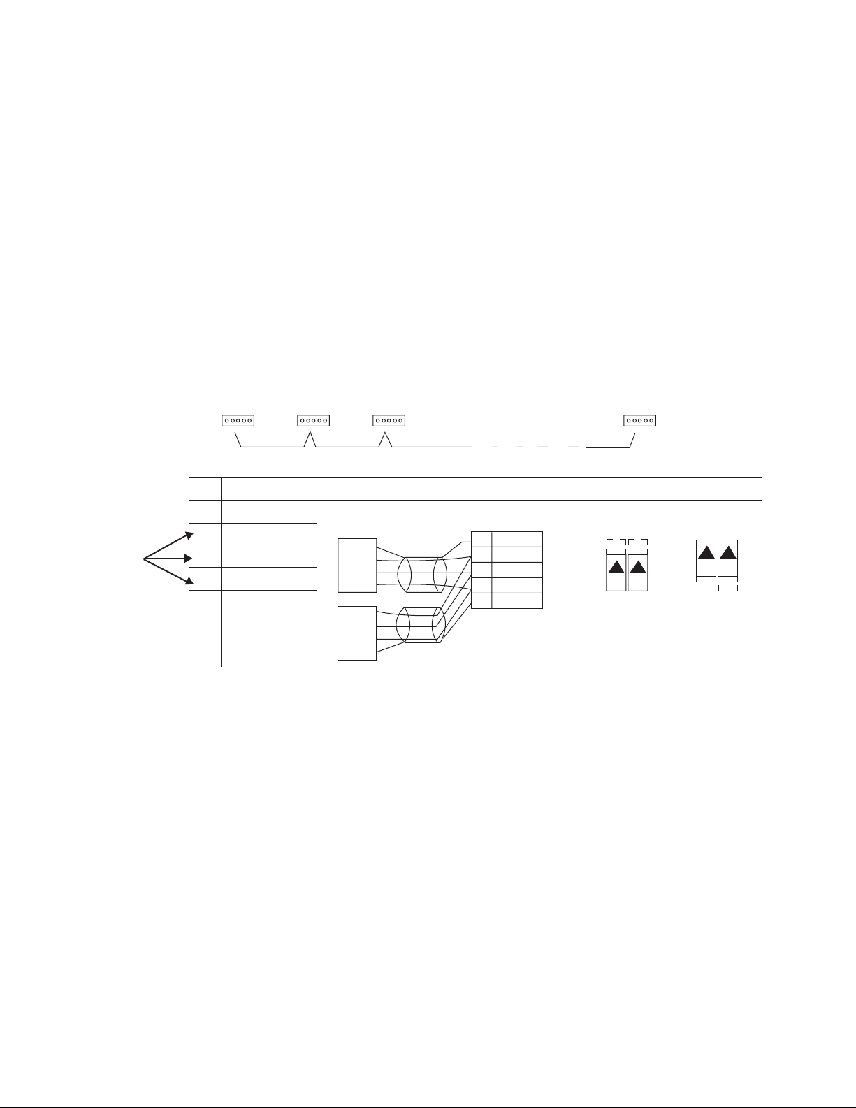
SETTING UP MODBUS COMMUNICATIONS
Modbus
Connections
for each
Aquavar
Terminated
Station
Station Station
X1 Identification
28 Screen
29 B
30 A
31 AGND
32 Screen
Hardware Description
RS485 Multidrop Application
Other Modbus Devices
SCR
B
A
GND
28 SCR
29 B
30 A
31 AGND
32 SCR
B
A
Terminated
Station
1
RS485 Interface
J2 J5 J2 J5
ON ON
off position on position
Bus Termination
GND
SCR
1
For functional descriptions, see “Standard Serial Communication” addendum.
ON ON
3
Page 4

WIRING
Physical wiring of the MODBUS communication cable is to the RS485 terminal block, 28, 29 and 30. Use the
screen connections if the cable has one.
NOTE: The only application macros that will work with Modbus communica-tions enabled are: [1] Single Pump,
[4] Constant Slv and [5] Speed Cntrl. See parameter 1102 Applic Macro. Multicontrol or Synchronous will not
work with MODBUS. Set macro to SINGLE PUMP, Constant Slv or Speed Cntrl.
Configure Modbus Serial Communications
1. Set EFB Station ID – This is the address of each Aquavar on the network. Each drive must have a unique
station ID on the network.
a. Go to Group 32 – EFB PROTOCOL, press SEL.
b. Go to parameter 3202 – EFB STATION ID, press EDIT.
c. Set desired station ID using the UP or DOWN arrows, press SAVE.
Valid addresses are 1 – 247.
NOTE: Address 0 is used to broadcast
messages to all slaves on the network.
NOTE: It is the user’s responsibility to ensure that reading and writing is done to the correct address
(Aquavar or node) in the network. Reading or writing to the wrong node can cause unexpected results.
2. Set EFB Baud Rate – The settings used must be the same on the Modbus Master and the slaves (Aquavar
CPC). Default rate is 9.6 kb/s.
a. Go to Group 32 – EFB PROTOCOL, press SEL.
b. Go to parameter 3203 – EFB BAUD RATE, press EDIT.
c. Set the desired Baud Rate using the UP or DOWN arrows, press SAVE.
Valid baud rates are:
1.2 kb/s 19.2 kb/s
2.4 kb/s 38.4 kb/s
4.8 kb/s 57.6 kb/s
9.6 kb/s 76.8 kb/s
4
Page 5

WIRING
3. Set EFB Parity – The settings used must be the same on the Modbus Master and the slaves (Aquavar CPC).
Default parity is 8N2 (8 data bits, no parity, two stop bits).
a. Go to Group 32 – EFB PROTOCOL, press SEL.
b. Go to parameter 3204 – EFB PARITY, press EDIT.
c. Set the desired Parity using the UP or DOWN arrows, press SAVE.
Valid Parity settings are:
0 = 8N1 – 8 data bits, No parity, one stop bit.
1 = 8N2 – 8 data bits, No parity, two stop bits.
2 = 8E1 – 8 data bits, Even parity, one stop bit.
3 = 8O1 – 8 data bits, Odd parity, one stop bit.
4. Set EFB Ctrl Profile – The Aquavar Profile may be the only the only profile that can be selected.
a. Go to Group 32 – EFB PROTOCOL, press SEL.
b. Go to parameter 3205 – EFB CTRL PROFILE, press EDIT.
c. Set the desired profile using the UP or DOWN arrows, press SAVE.
Valid Profile settings are:
1 = AQUAVAR
Activate Modbus Communications on the Aquavar
1. Go to Group 30 – Options, press SEL.
2. Press Edit.
3. Using the UP or DOWN keys, select [1] STD MODBUS.
4. Press SAVE. Modbus Communications are now active.
5
Page 6

SETTING DRIVE PARAMETERS
Note: With Modbus, any parameter can be accessed using the format: “4” followed by the parameter
number. See the following example:
Changing Ramps 1 and 2 via Modbus from 5 to 10 seconds on a drive over 15 HP.
1. Set parameter 1102 (Applic Macro) to: [1] Single Pump, [4] Constant Slv, or [5] Speed Cntrl.
2. Configure and Setup Modbus Serial Communications
3. Ramp 1 is parameter 1301 and Ramp 2 is parameter 1302.
4. Write ‘100’ to Holding Register 41301. Assuming no errors occur during this transaction, 1301 (Ramp 1)
should now be set to 10.0 seconds.
Note: There is an implied decimal point that is not written between the first (from the right) and second
digit. Thus 100 = 10.0
5. Write ‘100’ to Holding Register 41302. 1302 (Ramp 2) should now be set to 10.0 seconds.
START / STOP CONTROL
Start
1. Set parameter 1102 (Applic Macro) to: [1] Single Pump, [4] Constant Slv, or [5] Speed Cntrl.
2. Configure and Setup Modbus Serial Communications
3. Set parameter 1201 to [1] Fieldbus
4. To Start, write ‘1’ to Register 00002. Register 00001 (Stop) must be set ‘0’. The rotation arrow on the display
should now be spinning and the drive will start if the actual pressure is below the setpoint.
5. Write ‘0’ to Register 00002. The drive will continue to run as long as
Register 00001 is ‘0’.
Stop
1. To Stop, write ‘1’ to Register 00001. Register 00002, should be set to ‘0’. The rotation arrow on the display
should stop rotating.
REMOTE SETTING OF SET POINT 1
1. Set parameter 1102 (Applic Macro) to: [1] Single Pump, [4] Constant Slv, or [5] Speed Cntrl.
2. Configure and Setup Modbus Serial Communications.
3. Set parameter 1601 to [0] Setp1.
4. Set parameter 1602 to [2] Fieldbus.
5. Write a value between ‘10000’ and ‘0’ (100.00% to 0% of Transducer Max) to Holding Register 40003.
Note: There is an implied decimal point that is not written between the second (from the right) and third
digit. Thus, 10000 = 100.00%.
6
Page 7

REMOTE SETTING OF SET POINT 1
For example, using the standard 300 PSI transducer supplied with the Aquavar CPC:
1. Parameter 1502 (Transducer Max) should be set to 300 PSI.
2. Parameter 1503 (Transducer Min) should be set to 0 PSI.
3. Setting to 60 PSI…
a. 60 PSI / 300 PSI = .2 or 20%
b. Write ‘2000’ to Holding Register 40003
4. Setting to 80 PSI…
a. 80 PSI / 300 PSI = ~.2667 or 26.67%
b. Write ’2667’ to Holding Register 40003
Speed Control through Modbus Interface
1. Set parameter 1102 (Applic Macro) to: [5] Speed Cntrl
2. Configure and Setup Modbus Serial Communications
3. Set parameter 1601 to [0] Setp1
4. Set parameter 1602 to [2] Fieldbus
5. Write a value between ‘10000’ and ‘0’ [100.00% to 0% of Maximum Freq (1401)] to Holding Register 40002.
Note: There is an implied decimal point that is not written between the second (from the right) and third
digit. Thus, 10000 = 100.00%.
For example, using a Maximum Freq of 60 Hz:
1. Parameter 1401 (Maximum Freq) should be set to 60Hz.
2. Parameter 1601 (SP1 / SP2 Select) should be set to 0psi.
3. Parameter 1602 (Set Point 1 Select) should be set to [2] Fieldbus
4. Setting to 60 Hz (Full Speed)…
a. 60 Hz / 60 Hz = 1 or 100%
b. Write ‘10000’ to Holding Register 40002.
Note: Writing to parameter 1403 will have no effect.
5. Setting to 30 Hz (Half Speed)…
a. 30 Hz / 60 Hz = .5 or 50%
b. Write ‘5000’ to Holding Register 40002.
Note: Writing to parameter 1403 will have no effect.
7
Page 8

0XXXX MAPPING MODBUS COILS / AQUAVAR CONTROL WORD
Modbus Ref. Internal Location R/W Command Value Notes:
00001 Control Word - Bit 0 R/W STOP
00002 Control Word - Bit 1 R/W START
00003 Control Word - Bit 2 n/a Reserved (Not Used)
00004 Control Word - Bit 3 n/a Reserved (Not Used)
00005 Control Word - Bit 4 R/W RESET
00006 Control Word - Bit 5 R/W EXT2
00007 Control Word - Bit 6 n/a Reserved (Not Used)
00008 Control Word - Bit 7 n/a Reserved (Not Used)
00009 Control Word - Bit 8 n/a Reserved (Not Used)
00010 Control Word - Bit 9 n/a Reserved (Not Used)
00011 Control Word - Bit 10 n/a Reserved (Not Used)
00012 Control Word - Bit 11 n/a Reserved (Not Used)
00013 Control Word - Bit 12 n/a Reserved (Not Used)
00014 Control Word - Bit 13 n/a Reserved (Not Used)
00015 Control Word - Bit 14 n/a Reserved (Not Used)
00016 Control Word - Bit 15 n/a Reserved (Not Used)
00017 Control Word - Bit 16 n/a Reserved (Not Used)
00018 Control Word - Bit 17 n/a Reserved (Not Used)
00019 Control Word - Bit 18 n/a Reserved (Not Used)
00020 Control Word - Bit 19 n/a Reserved (Not Used)
00021 Control Word - Bit 20 n/a Reserved (Not Used)
00022 Control Word - Bit 21 n/a Reserved (Not Used)
00023 Control Word - Bit 22 n/a Reserved (Not Used)
00024 Control Word - Bit 23 n/a Reserved (Not Used)
00025 Control Word - Bit 24 n/a Reserved (Not Used)
00026 Control Word - Bit 25 n/a Reserved (Not Used)
00027 Control Word - Bit 26 n/a Reserved (Not Used)
00028 Control Word - Bit 27 n/a Reserved (Not Used)
00029 Control Word - Bit 28 n/a Reserved (Not Used)
00030 Control Word - Bit 29 n/a Reserved (Not Used)
00031 Control Word - Bit 30 n/a Reserved (Not Used)
00032 Control Word - Bit 31 n/a Reserved (Not Used)
00033 Not used in CW R/W RELAY OUTPUT 1
00034 Not used in CW R/W RELAY OUTPUT 2
00035 Not used in CW R/W RELAY OUTPUT 3
00036 RESERVED n/a Reserved (Not Used)
00037 RESERVED n/a Reserved (Not Used)
00038 RESERVED n/a Reserved (Not Used)
Supported Function Codes
01 - Read Coil Status 05 - Force Single Coil 15 - Force Multiple Coils (0x0F Hex)
1 = STOP,
0 = (no op)
1 = START,
0 = (no op)
1 = RESET,
0 = (no op)
1 = EXT2,
0 = EXT1
1 = Energize,
0 = Denergize
1 = Energize,
0 = Denergize
1 = Energize,
0 = Denergize
STOP Bit Must be
set to 0 to start
drive via Modbus.
If both STOP and
START are set to 1,
drive will stop or
remain stopped.
8
Page 9

1XXXX MAPPING - MODBUS DISCRETE INPUTS / AQUAVAR STATUS WORD
Modbus Ref. Internal Location R/W Indication Value
10001 Status Word - Bit 0 R READY
10002 Status Word - Bit 1 R ENABLED
10003 Status Word - Bit 2 R STARTED
10004 Status Word - Bit 3 R Reserved (Not Used)
10005 Status Word - Bit 4 R ZERO_SPEED
10006 Status Word - Bit 5 R ACCELERATE
10007 Status Word - Bit 6 R DECELERATE
10008 Status Word - Bit 7 R AT_SPEED
10009 Status Word - Bit 8 R Reserved (Not Used)
10010 Status Word - Bit 9 R Reserved (Not Used)
10011 Status Word - Bit 10 R Reserved (Not Used)
10012 Status Word - Bit 11 R Reserved (Not Used)
10013 Status Word - Bit 12 R PANEL_LOCAL
10014 Status Word - Bit 13 R Reserved (Not Used)
10015 Status Word - Bit 14 R EXT2_ACT
10016 Status Word - Bit 15 R FA U LT
10017 Status Word - Bit 16 R ALARM
10018 Status Word - Bit 17 R REQ_MAINT
10019 Status Word - Bit 18 R Reserved (Not Used)
10020 Status Word - Bit 19 R LOCAL LOCK
10021 Status Word - Bit 20 R Reserved (Not Used)
10022 Status Word - Bit 21 R Reserved (Not Used)
10023 Status Word - Bit 22 R Reserved (Not Used)
10024 Status Word - Bit 23 R Reserved (Not Used)
10025 Status Word - Bit 24 R Reserved (Not Used)
10026 Status Word - Bit 25 R Reserved (Not Used)
10027 Status Word - Bit 26 R Reserved (Not Used)
10028 Status Word - Bit 27 R Reserved (Not Used)
10029 Status Word - Bit 28 R Reserved (Not Used)
10030 Status Word - Bit 29 R Reserved (Not Used)
10031 Status Word - Bit 30 R Reserved (Not Used)
10032 Status Word - Bit 31 R Reserved (Not Used)
10033 DI1 R DI1 0 = OFF, 1 = ON
10034 DI2 R DI2 0 = OFF, 1 = ON
10035 DI3 R DI3 0 = OFF, 1 = ON
10036 DI4 R DI4 0 = OFF, 1 = ON
10037 DI5 R DI5 0 = OFF, 1 = ON
10038 DI6 R DI6 0 = OFF, 1 = ON
Supported Function Codes
02 - Read Input Status
0 = NOT MAX FREQUENCY
1 = READY,
0 = NOT READY
1 = ENABLED,
0 = NOT ENABLED
1= STARTED,
0 = NOT STARTED
1 = ACCELERATING,
0 = NOT ACCELERATING
1 = DECELERATING,
0 = NOT DECELERATING
1 = MAX FREQUENCY,
0 = NOT LOCAL
1 = LOCAL
0 =Speed Control Mode
1 = All Other Macros
0 = NO FAULT,
0 = NO ALARM,
1 = ALARM
0 = LOCAL LOCK OFF,
1 = LOCAL LOCK ON
1 = 0 Hz,
0 = > 0 Hz
1 = FAULT
9
Page 10

3XXXX MAPPING - MODBUS INPUTS
Modbus Ref. VFD Signal R/W Remarks
30001 AI1 R
30002 AI2 (Transducer) R
Supported Function Codes
04 - Read Input Registers
This Register shall report the level of
Analog Input 1 (0 …100%)
This Register shall report the level of
Analog Input 2 (0 …100%)
10
Page 11

4XXXX REGISTER MAPPING
Modbus Ref. Contents R/W Remarks
40002 Reference 1 R/W
40003 Reference 2 (Setpoint) R/W
40005
40006
40007
40008
40009
40010
40011
40012
40031 Aquavar Control Word LSW R/W
40032 Aquavar Control Word MSW R
40033 Aquavar Status Word LSW R
40034 Aquavar Status Word MSW R
Actual 1
(Select using 3210)
Actual 2
(Select using 3211)
Actual 3
(Select using 3213)
Actual 4
(Select using 3214)
Actual 5
(Select using 3214)
Actual 6
(Select using 3214)
Actual 7
(Select using 3214)
Actual 8
(Select using 3214)
R
R
R
R
R
R
R
R
Range = 0 … 10000 (0 … 100.00%) of Transducer range.
NOTE: Group 16 Setpoint Select must be set to Fieldbus
Use for Speed Control Macro Only
Range = 0 … 10000 (0 … 100.00%)
Remote Setpoint via Modbus
e.g. 0 = 0 psi and 10000 = 300 PSI.
By default, stores nothing. Use parameter 3210 to
select an actual value for this register.
e.g. 3210 = 0101, 40006 = Motor Freq.
By default, stores nothing. Use parameter 3211 to
select an actual value for this register.
By default, stores nothing. Use parameter 3213 to
select an actual value for this register.
By default, stores nothing. Use parameter 3214 to
select an actual value for this register.
By default, stores nothing. Use parameter 3215 to
select an actual value for this register.
By default, stores nothing. Use parameter 3216 to
select an actual value for this register.
By default, stores nothing. Use parameter 3217 to
select an actual value for this register.
By default, stores nothing. Use parameter 3218 to
select an actual value for this register.
Maps directly to the Least Significant Word of the
Aquavar profile’s CONTROL WORD.
Maps directly to the Most Significant Word of the
Aquavar profile’s CONTROL WORD.
Maps directly to the Least Significant Word of the
Aquavar profile’s STATUS WORD.
Maps directly to the Most Significant Word of the
Aquavar profile’s STATUS WORD.
DRIVE PARAMETERS
Group 1 VFD Signal R/W Set Value (Dec)
40101 Motor Frequency R —
40102 Motor Current R —
40103 Motor Power R —
40104 DC Bus Voltage R —
40105 Motor Voltage R —
40106 Drive Temp R —
40107 VFD On Time R —
40108 Run Time R —
40109 KWh Counter R —
40110 DI6-1 Status R —
40111 AI1 R —
40112 AI2 Trnsdcr Fdbk R —
40113 RO3-1 Status R —
40114 AO1 (mA) R —
40115 AO2 (mA) R —
40116 Last Fault R —
40117 Previous Fault 1 R —
40118 Previous Fault 2 R —
11
Page 12

4XXXX REGISTER MAPPING
DRIVE PARAMETERS
Group 1 VFD Signal R/W Set Value (Dec)
40119 Fault Time 1 R —
40120 Fault Time 2 R —
40121 Speed at Flt R —
40122 Freq at Flt R —
40123 Voltage at Flt R —
40124 Current at Flt R —
40125 Status at Flt R —
40126 DI 6-1 At Fault R —
40127 Drive On Time Hi R —
40128 Drive On Time Lo R —
Group 2 VFD Signal R/W Set Value (Dec)
40201 Set Point R —
40202 Actual R —
40203 Pump Speed R —
40204 Wire to Water Power R —
40205 Set Point #1 R —
40206 Set Point #2 R —
40207 Energy Savings R —
40208 Pump Number R
40209 Used Set Point R —
Stopped [0]
Pump 1 [1]
Pump 2 [2]
Pump 3 [3]
Pump 4 [4]
Group 3 VFD Signal R/W Set Value (Hex)
40301 FB CMD Word 1 R —
40302 FB CMD Word 2 R —
40303 FB STS Word 1 R —
40304 FB STS Word 2 R —
40305 Fault Word 1 R —
40306 Fault Word 2 R —
40307 Fault Word 3 R —
40308 Alarm Word 1 R HEX
40309 Alarm Word 2 R HEX
40310 AV Alarm Word R HEX
40311 AV Fault Word R —
12
Page 13

4XXXX REGISTER MAPPING
DRIVE PARAMETERS
Group 10 VFD Signal R/W Set Value (Dec)
41001 Parameter Lock R/W Locked [0], Open [1]
41002 Pass Code R/W
41003 Local Lock R/W Off [0], On [1]
41004 Parameter Save R/W Done [0], Save… [1]
41005 New Pass Code R/W
41006 Set Point Lock R/W Off [0], On [1]
Group 11 VFD Signal R/W Set Value (Dec)
41101 Language R/W
41102 Application Macro R/W
41103 Motor Nom Voltage R/W
41104 Motor Nom Current R/W
41105 Motor Nom Freq R/W
41106 Motor Nom RPM R/W
41107 Motor Nominal Power R/W
English [0]
Espanol [1]
Francais [2]
Single Pump [1]
Synchronous [2]
Multicontrol [3]
Constant Slv [4]
Speed Contrl [5]
Group 12 VFD Signal R/W Set Value (Dec)
41201 Start/Stop R/W
41202 Auto Restart R/W On [0], Off [1]
41203 Test Run R/W
41204 Test Speed % (FL) R/W
41205 Test Run Delay R/W
41206 Motor Jog R/W
Keypad [0]
Fieldbus [1]
Not Sel [0]
Auto [1]
Manual [2]
Disable [0]
Jog [1]
Group 13 VFD Signal R/W Set Value (Dec)
41301 Ramp1 Fast Accel R/W
41302 Ramp2 Fast Decel R/W
41303 Ramp3 Slow Accel R/W
41304 Ramp4 Slow Decel R/W
41305 Ramp Hysteresis R/W
41306 Reg Window R/W
13
Page 14

4XXXX REGISTER MAPPING
DRIVE PARAMETERS
Group 14 VFD Signal R/W Set Value (Dec)
41401 Maximum Freq R/W
41402 Minimum Freq R/W
41403 Config Speed Min R/W
41404 Stp Dely Min Spd R/W
41405 Restart Value R/W
41406 Restart Delay R/W
41407 Priming Delay R/W
Group 15 VFD Signal R/W Set Value (Dec)
41501 Transducer Unit R/W
41502 Transducer Max R/W
41503 Transducer Min R/W
41506 Sensor Min R/W
0 [0]
Minimum Freq [1]
% [4]
C [9]
F [16]
GPM [24]
PSI [25]
ft [27]
4 mA [0]
Tune [1]
Group 16 VFD Signal R/W Set Value (Dec)
Setp1 [0]
41601 Sp1/Sp2 Select R/W
41602 Set Point 1 Sel R/W
41603 Set Point 2 Sel R/W
41604 AI1 Minimum R/W
DI4 [1]
Fieldbus [2]
Keypad [0]
AI1 [1]
Fieldbus [2]
Keypad [0]
AI1 [1]
Fieldbus [2]
0V [0]
4 mA [1]
Tune [2]
Group 18 VFD Signal R/W Set Value (Dec)
Not Sel [0]
Run [1]
Ready [2]
Fault [3]
41801 Relay Output 1 R/W
Low Water [4]
Pump Prtct [5]
Start Slv [6]
Stand By [7]
Active [8]
41802 RO 1 On Delay R/W
41803 RO 1 Off Delay R/W
14
Page 15

4XXXX REGISTER MAPPING
DRIVE PARAMETERS
Group 18 VFD Signal R/W Set Value (Dec)
41804 Relay Output 2 R/W
41805 RO 2 On Delay R/W
41806 RO 2 Off Delay R/W
41807 Relay Output 3 R/W
41808 RO 3 On Delay R/W
41809 RO 3 Off Delay R/W
Not Sel [0]
Run [1]
Ready [2]
Fault [3]
Low Water [4]
Pump Prtct [5]
Start Slv [6]
Stand By [7]
Active [8]
Not Sel [0]
Run [1]
Ready [2]
Fault [3]
Low Water [4]
Pump Prtct [5]
Start Slv [6]
Stand By [7]
Active [8]
Group 19 VFD Signal R/W Set Value (Dec)
Not Sel [0]
Motor Freq [101]
41901 AO1 Content Sel R/W
41902 AO1 Content Min R/W
41903 AO1 Content Max R/W
41904 Minimum AO1 R/W
41905 Maximum AO1 R/W
41906 AO2 Content Sel R/W
41907 AO2 Content Min R/W
41908 AO2 Content Max R/W
41909 Minimum AO2 R/W
41910 Maximum AO2 R/W
Motor Curren [102]
Motor Power [103]
Actual [202]
Energy Savin [207]
Not Sel [0]
Motor Freq [101]
Motor Curren [102]
Motor Power [103]
Actual [202]
Energy Savin [207]
15
Page 16

4XXXX REGISTER MAPPING
DRIVE PARAMETERS
Group 21 VFD Signal R/W Set Value (Dec)
42101 Regulation Mode R/W
42102 Press Inc Speed R/W
42103 Press Inc R/W
Group 22 VFD Signal R/W Set Value (Dec)
42201 Value Decrease R/W
42202 Value Increase R/W
42203 Enable Sequence R/W
42204 Switch Lead Lag R/W
42205 Sync Limit R/W
42206 Sync Window R/W
42207 Pump Address R/W
42209 Setp2 Source R/W
Normal [0]
Inverse [1]
Off [0]
Addr 1 [1]
Addr 2 [2]
Addr 3 [3]
Addr 4 [4]
Group 24 VFD Signal R/W Set Value (Dec)
42401 Keypad Failure R/W
42402 Pump Protct Ctrl R/W
42403 Protection Limit R/W
42404 Protection Delay R/W
42405 Low Water R/W
42406 Error Reset R/W
42407 Reset Delay R/W
42408 Run Enable R/W
42409 Comm Fault Func R/W
42410 Comm Fault Time R/W
Fault [1]
Disable [3]
Disable [0]
Warning [1]
Warning & Ct [2]
Fault [3]
Disable [0]
Warning [1]
Warn & Ctrl [3]
Fault [3]
Disable [0]
Enable [1]
Not Sel [0]
Fault [1]
Last Speed [3]
16
Page 17

4XXXX REGISTER MAPPING
DRIVE PARAMETERS
Group 25 VFD Signal R/W Set Value (Dec)
42501 NR of Trials R/W
42502 Trial Time R/W
42503 Delay Time R/W
42504 AR Overcurrent R/W
42505 AR Undercurrent R/W
42506 AR Undervoltage R/W
42507 AR AI<Min R/W
Group 26 VFD Signal R/W Set Value (Dec)
42601 Energy Cost R/W
42602 Baseline Power R/W
42603 Saving Scale R/W
42604 Energy Save Mthd R/W
42605 Reset Counters R/W No [0]
Disable [0]
Enable [1]
Disable [0]
Enable [1]
Disable [0]
Enable [1]
Disable [0]
Enable [1]
Savings Op1 [0]
Savings Op2 [1]
Group 30 VFD Signal R/W Set Value (Dec)
Not Sel [0]
43001 Comm Prot Sel R/W
Std Modbus [1]
Aquavar [3]
Ext Fba [4]
Group 31 VFD Signal R/W Set Value (Dec)
NOTE: This group is setup by automatically an External Fieldbus Adaptor. Refer to the External Fieldbus Adaptor
manual for more information.
17
Page 18

4XXXX REGISTER MAPPING
DRIVE PARAMETERS
Group 32 VFD Signal R/W Set Value (Dec)
43201 EFB Protocol ID R/W Do not edit!
43202 EFB Station ID R/W
43203 EFB Baud Rate R/W
43204 EFB Parity R/W
43205 EFB CTRL Profile R/W
43206 EFB OK Messages R/W
43207 EFB CRC Errors R/W
43208 EFB UART Errors R/W
43209 EFB Status R/W
43210 EFB Par 10 R/W
43211 EFB Par 11 R/W
43212 EFB Par 12 R/W
43213 EFB Par 13 R/W
43214 EFB Par 14 R/W
43215 EFB Par 15 R/W
43216 EFB Par 16 R/W
43217 EFB Par 17 R/W
43218 EFB Par 18 R/W
43219 EFB Par 19 R/W
43220 EFB Par 20 R/W
8N1 [0]
8N2 [1]
8E1 [2]
8O1 [3]
ABB Drives [0]
ACS550 [1]
Idle [0]
Execut Init [1]
Time Out [2]
Config Error [3]
Off-Line [4]
On-Line [5]
Reset [6]
Listen Only [7]
18
Group 33 VFD Signal R/W Set Value (Dec)
43301 Station ID R/W
43302 Baud Rate R/W
8N1 [0]
43303 Parity R/W
43304 OK Messages R/W
43305 Parity Errors R/W
43306 Frame Errors R/W
43307 Buffer Overruns R/W
43308 CRC Errors R/W
8N2 [1]
8E1 [2]
8O1 [3]
Page 19

4XXXX REGISTER MAPPING
DRIVE PARAMETERS
Group VFD Signal R/W Set Value (Dec)
45001 Switching Freq R/W
Group 51 VFD Signal R/W Set Value (Dec)
45101 Cooling Fan Trig R/W
45102 Cooling Fan Act R/W
45103 Revolution Trig R/W
45104 Revolution Act R/W
45105 Run Time Trig R/W
45106 Run Time Act R/W
45107 User MWh Trig R/W
45108 User MWh Act R/W
Group 99 VFD Signal R/W Set Value (Dec)
49901 FW Version R
49902 Drive Rating R
Supported Function Codes
03 - Read 4xxxx Registers
06 - Preset Single 4xxxx Register
16 - Preset Multiple 4xxxx Registers (0x10 Hex)
23 - Read/Write 4xxxx Registers (0x17 Hex)
19
Page 20

CENTRIPRO LIMITED WARRANTY
This warranty applies to all Aquavar CPC controllers manufactured by Xylem, Inc.
Any part or parts found to be defective within the warranty period shall be replaced at no charge to the dealer during the warranty period. The warranty period shall exist
for a period of twenty-four (24) months from date of installation or thirty (30) months from date of manufacture, whichever period is shorter.
A dealer who believes that a warranty claim exists must contact the authorized CentriPro distributor from whom the controller was purchased and furnish complete details
regarding the claim. The distributor is authorized to adjust any warranty claims utilizing the CentriPro Customer Service Department.
The warranty excludes:
(a) Labor, transportation and related costs incurred by the dealer;
(b) Reinstallation costs of repaired equipment;
(c) Reinstallation costs of replacement equipment;
(d) Consequential damages of any kind; and,
(e) Reimbursement for loss caused by interruption of service.
For purposes of this warranty, the following terms have these definitions:
(1) “Distributor” means any individual, partnership, corporation, association, or other legal relationship that stands between CentriPro and the dealer in purchases,
consignments or contracts for sale of the subject controllers.
(2) “Dealer” means any individual, partnership, corporation, association, or other legal relationship which engages in the business of selling or leasing controllers to
customers.
(3) “Customer” means any entity who buys or leases the subject controllers from a dealer. The “customer” may mean an individual, partnership, corporation, limited
liability company, association or other legal entity which may engage in any type of business.
THIS WARRANTY EXTENDS TO THE DEALER ONLY.
Xylem, Inc.
2881 East Bayard Street Ext., Suite A
Seneca Falls, NY 13148
Phone: (800) 453-6777
Fax: (888) 322-5877
www.centripro.com
CentriPro and Aquavar are trademarks of Xylem Inc. or one of its subsidiaries.
© 2012 Xylem Inc. ADAQCPC R1 February 2013
 Loading...