

Page 1
INSTRUCTION MANUAL
AC8652
REVISION C
INSTALLER: PLEASE LEAVE THIS MANUAL FOR THE OWNER’S USE.
2000 Series
Frame Mounted Pumps
Page 2

TABLE OF CONTENTS
DESCRIPTION......................................................3
PUMP APPLICATION...........................................3
SAFETY INSTRUCTIONS ....................................3
ELECTRICAL SAFETY: ................................3
THERMAL SAFETY: .....................................3
MECHANICAL SAFETY:...............................3
PUMP LOCATION ................................................5
INSTALLATION ....................................................6
LEVELING .....................................................6
GROUTING ...................................................7
SEE ANSI/OSHA COUPLER GUARD
REMOVAL/INSTALLATION ..................7
ALIGNMENT PROCEDURE .........................7
ANSI/OSHA COUPLER GUARD
REMOVAL/INSTALLATION ..................7
ROTATION ..................................................12
PIPING ................................................................12
PRIMING AND STARTING.................................13
LUBRICATION ............................................13
GENERAL INSTRUCTIONS .......................13
SERVICE INSTRUCTIONS ................................13
IMPELLER REMOVAL ................................14
DISMANTLING THE STUFFING BOX........14
FRAME DISASSEMBLY .............................14
CASING WEARING RING REMOVAL
(OPTIONAL) ........................................14
ASSEMBLY PROCEDURES..............................15
FRAME ASSEMBLY....................................15
STUFFING BOX ASSEMBLY .....................15
IMPELLER INSTALLATION...............................16
FINAL ASSEMBLY.............................................16
REPAIR PARTS LIST.........................................19
ORDERING PARTS............................................20
DEALER SERVICING.........................................20
NOTE
The information contained in this book is intended
to assist operating personnel by providing
information on the characteristics of the purchased
equipment.
It does not relieve the user of their responsibility of
using accepted engineering practices in the
installation, operation, and maintenance of this
equipment.
Any further questions, contact AC Fire Pump,
(847) 966-3700.
2
Page 3
DESCRIPTION
The Series 2000 Frame Mounted Centrifugal
Pump is an end suction centerline discharge
pump. The Series 2000 Pump’s rear pull out
construction makes servicing simpler and faster.
The hydraulically balanced impellers extend
bearing life and assure smoother, quieter
operation.
THERMAL SAFETY:
WARNING: Extreme Temperature
Hazard
If pump, motor, or piping is operating at extremely
high or low temperature, guarding or insulation is
required. Failure to follow these instructions could
result in serious personal injury or death, and
property damage.
PUMP APPLICATION
The Series 2000 Pump’s available constructions
and sizes make it ideal for applications in general
industry, water supply, water transfer, condenser,
and chilled and hot water circulation.
SAFETY INSTRUCTIONS
SAFETY
INSTRUCTIONS
This safety alert symbol will be used in this manual
and on the pump safety instruction decals to draw
attention to safety related instructions. When used
the safety alert symbol means ATTENTION!
BECOME ALERT! YOUR SAFETY IS INVOLVED!
FAILURE TO FOLLOW THE INSTRUCTIONS
MAY RESULT IN A SAFETY HAZARD.
Your Series 2000 pump should have the following
safety instruction decals located approximately as
shown. If the decals are missing or are illegible
contact your local AC Fire Pump Systems
representative for a replacement. (Fig. 1)
ELECTRICAL SAFETY:
MECHANICAL SAFETY:
WARNING: Unexpected Startup Hazard
Disconnect and lockout power before
servicing. Failure to follow these instructions could
result in serious personal injury or death, and
property damage.
WARNING: Excessive System Pressure
Hazard
The maximum working pressure of the pump is
listed on the nameplate, do not exceed this
pressure. Failure to follow these instructions could
result in serious personal injury or death, and
property damage.
WARNING: Excessive Pressure Hazard
Volumetric Expansion
The heating of water and other fluids causes
volumetric expansion. The associated forces may
cause failure of system components and release
of high temperature fluids. Installing properly sized
and located compression tanks and pressure relief
valves will prevent this. Failure to follow these
instructions could result in serious personal injury
or death, and property damage.
WARNING: Electrical Shock Hazard
Electrical connections to be made by a
qualified electrician in accordance with all
applicable codes, ordinances, and good practices.
Failure to follow these instructions could result in
serious personal injury or death, and property
damage.
WARNING: Electrical Overload Hazard
Three phase motors must have properly
sized heaters to provide overload and under
voltage protection. Single-phase motors have
built-in overload protectors. Failure to follow these
instructions could result in serious personal injury
or death, and property damage.
3
Page 4
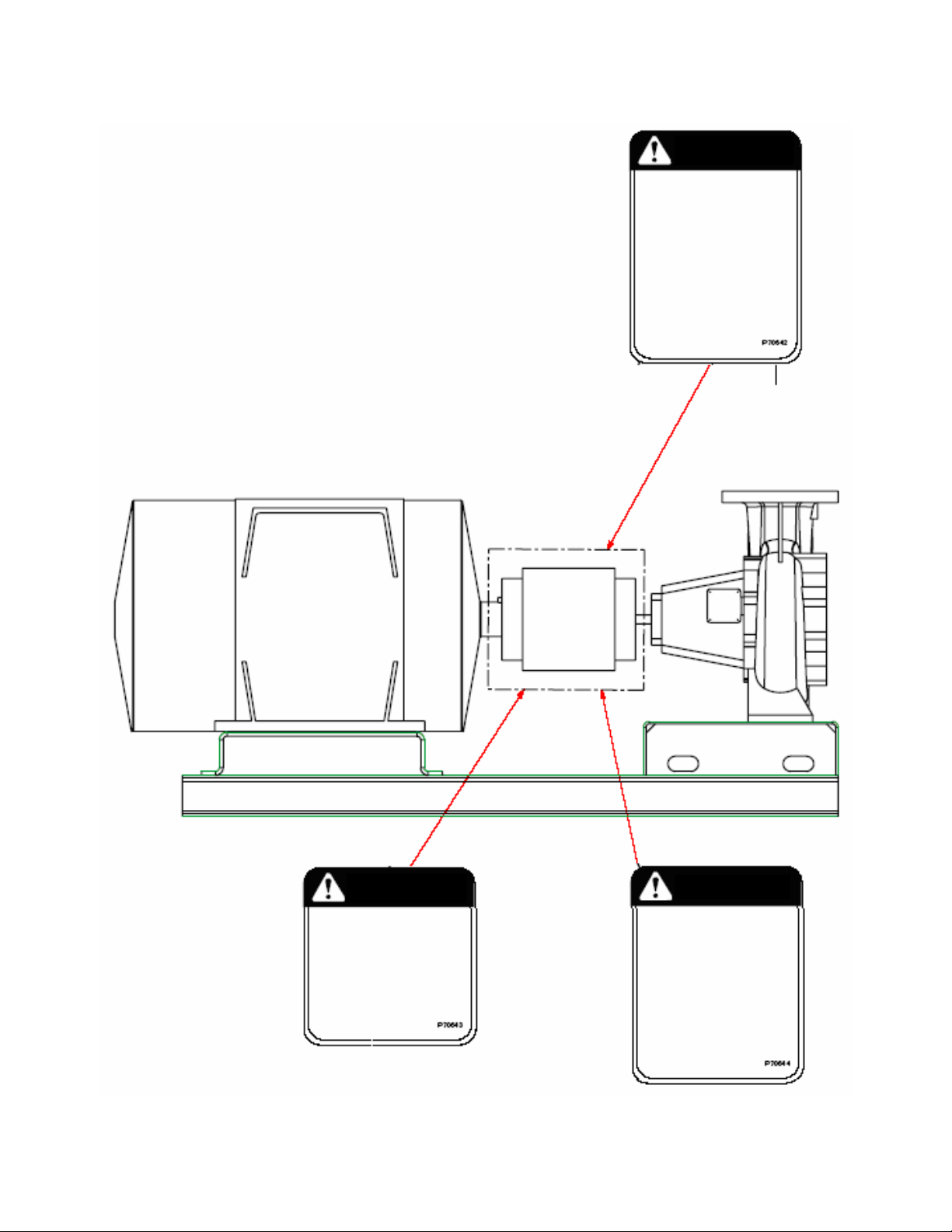
WARNING
ROTATING COMPONENTS
DISCONNECT AND LOCK OUT
POWER BEFORE SERVICING.
DO NOT OPERATE WITHOUT ALL
GUARDS IN PLACE.
CONSULT INSTALLATION AND
SERVICE INSTRUCTION SHEET
BEFORE OPERATING OR
SERVICING.
FAILURE TO FOLLOW
INSTRUCTIONS COULD RESULT
IN INJURY OR DEATH.
(2) REQUIRED
(1 EACH SIDE)
WARNING
EYEBOLTS OR LIFTING
LUGS IF PROVIDED ARE
FOR LIFTING ONLY THE
COMPONENTS TO WHICH
THEY ARE ATTACHED.
FAILURE TO FOLLOW
INSTRUCTIONS COULD
RESULT IN INJURY OR
DEATH.
FIG. 1
4
CAUTION
DO NOT RUN PUMP DRY, SEAL
DAMAGE MAY OCCUR.
INSPECT PUMP SEAL
REGULARY FOR LEAKS,
REPLACE AS REQUIRED.
FOR LUBRICATION
REQUIREMENTS, CONSULT
SERVICE INSTRUCTIONS.
FAILURE TO FOLLOW
INSTRUCTIONS COULD RESULT
IN INJURY OR PROPERTY
DAMAGE.
Page 5
PUMP LOCATION
Locate the pump so there is sufficient room for
inspection, maintenance, and service. If the use of
a hoist or tackle is needed, allow ample head
room.
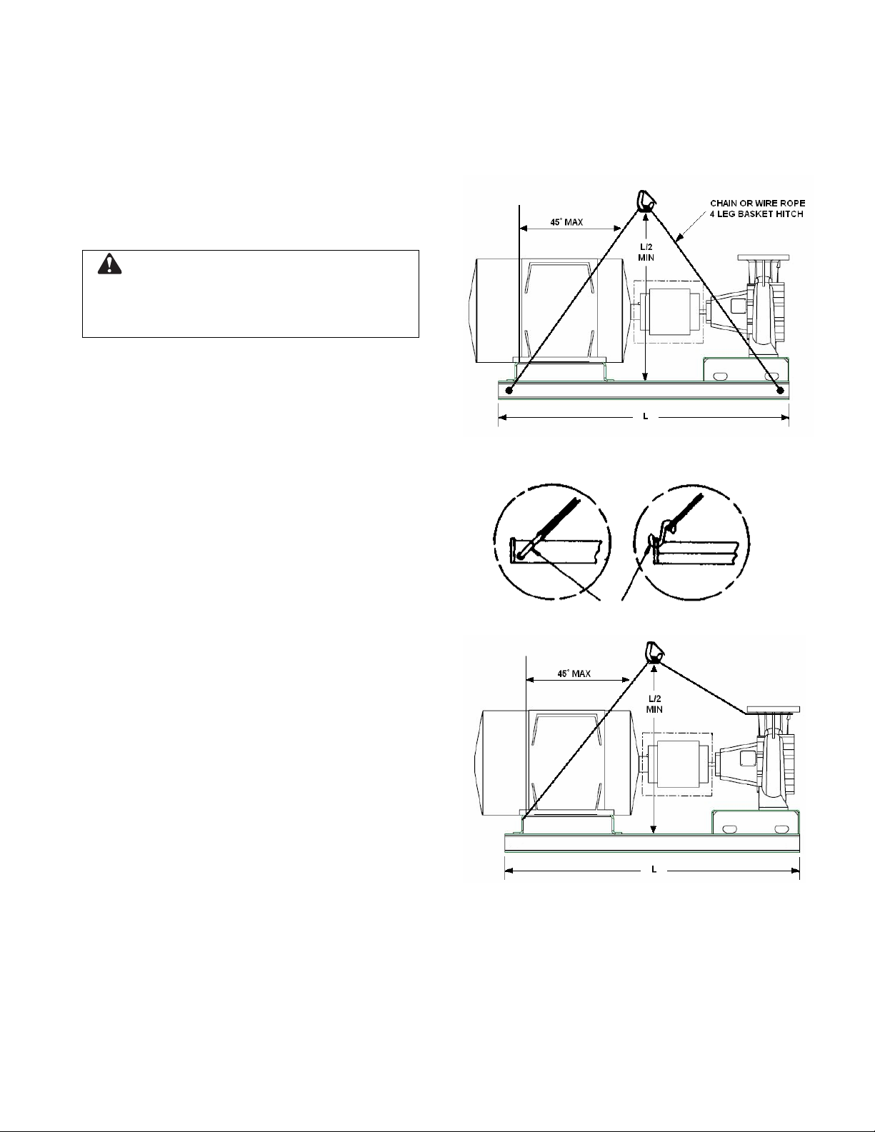
WARNING
Eyebolts or lifting lugs if provided are for
lifting only the components to which they are
attached. Failure to follow instructions could result
in injury or death.
If lifting of the entire pump is required, do so with
slings placed as shown. (Fig. 2 & 3)
The best pump location for sound and vibration
absorption is on a concrete floor with subsoil
underneath. If the pump location is overhead,
special precautions should be undertaken to
reduce possible sound transmission, consult a
sound specialist.
If the pump is not on a closed system, it should be
placed as near as possible to the source of the
liquid supply, and located to permit installation with
the fewest number of bends or elbows in the
suction pipe.
FIG. 2 – Bases with Lifting Holes
The installation must be evaluated to determine
that the Net Positive Suction Head Available
(NPSHA) meets or exceeds the Net Positive
Suction Head Required (NPSHR), as stated by the
pump performance curve.
IMPORTANT: Do not install and operate Series
2000 Pumps in closed systems unless the system
is constructed with properly sized safety devices
and control devices. Such devices include the use
of properly sized and located pressure relief
valves, compression tanks, pressure controls,
temperature controls, and flow controls as
appropriate. If the system does not include these
devices, consult the responsible engineer or
architect before making pumps operational.
“S” Hooks
FIG. 2A FIG. 2B
FIG. 3 – Bases without Lifting Holes
5
Page 6
INSTALLATION
This pump is built to provide years of service if
installed properly and attached to a suitable
foundation. A base of concrete weighing 2-1/2
times the weight of the pump is recommended.
(Check the shipping ticket for pump weight.)
DRILL AND TAPER REAM
AFTER ALIGNMENT
SHIMS
ADJUST TO ALIGN
1/2" - 1-1/2"
8" - 12"
TUBE AT LEAST 4"
LONG
2 TIMES BOLT DIA.
OR 1/2" MIN.
SIDE CLEARANCE
TO PROVIDE
BOLT CLEARANCE
HOOK
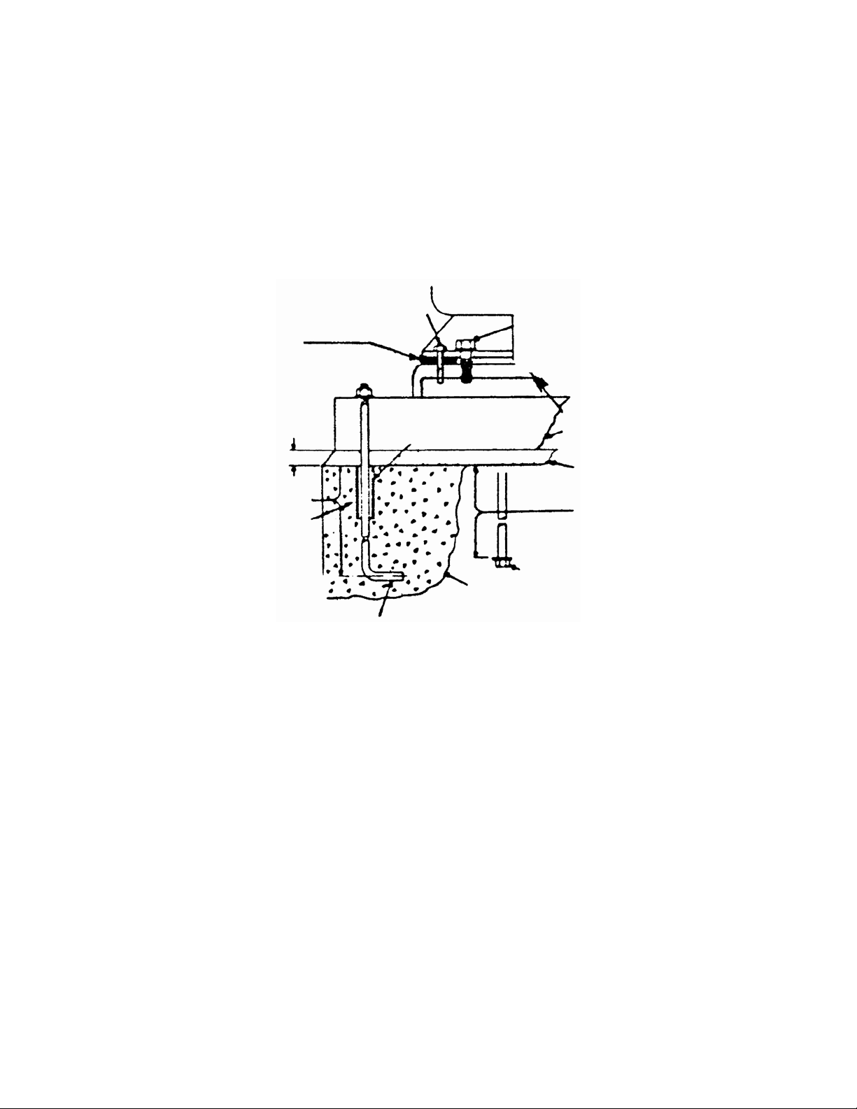
If possible, tie the concrete pad in with the finished
floor. Use foundation bolts and larger pipe-sleeves
to give room for final bolt location. (Fig. 4)
MOTOR
TIGHTEN BOLTS BEFORE
CHECKING ALIGNMENT
BASEPLATE
ASSEMBLY
GROUT
12" - 18"
ALTERNATE BOLT
AND WASHER
FOUNDATION TO SUIT
LOCAL CONDITIONS
LEVELING
Place the pump on its concrete foundation
supporting it with steel wedges or shims
totaling 1" in thickness. These wedges or
shims should be put on both sides of each
anchor-bolt to provide a means of leveling the
base.
FIG. 4
IT IS VERY IMPORTANT THAT THE PUMPBASE BE SET LEVEL TO AVOID ANY
MECHANICAL DIFFICULTIES WITH THE
MOTOR OR PUMP. THIS PUMP WAS
PROPERLY ALIGNED (IF FURNISHED WITH
A MOTOR) AT THE FACTORY. HOWEVER,
SINCE ALL PUMP BASES ARE FLEXIBLE
THEY MAY SPRING AND TWIST DURING
SHIPMENT. DON’T PIPE THE PUMP UNTIL
IT IS REALIGNED. AFTER PIPING IS
COMPLETED AND AFTER THE PUMP IS
GROUTED-IN AND BOLTED-DOWN, ALIGN
IT AGAIN. IT MAY BE NECESSARY TO READJUST THE ALIGNMENT FROM TIME TO
TIME WHILE THE UNIT AND FOUNDATION
ARE NEW.
6
Page 7

GROUTING
After the pump has been leveled, securely
bolted to the floor, and properly aligned, a
good grade of non-shrinking grout should be
poured inside the pump base. To hold
wedges or shims in place, allow the grout to
flow around them.
ANSI/OSHA COUPLER GUARD
REMOVAL/INSTALLATION
WARNING: Unexpected Start-up Hazard
Disconnect and lock out power before
servicing. Failure to follow these instructions could
result in serious personal injury or death and
property damage.
SEE ANSI/OSHA COUPLER GUARD
REMOVAL/INSTALLATION
(SEE BELOW)
ALIGNMENT PROCEDURE
NOTE: A flexible coupling will only
compensate for small amounts of
misalignment. Permissible misalignment will
vary with the make of coupling. Consult
coupling manufacturer’s data when in doubt.
Allowances are to be made for thermal
expansion during cold alignment, so that the
coupling will be aligned at operating
temperature. In all cases, a coupling must be
in alignment for continuous operation. Even
though the coupling may be lubricated,
misalignment causes excessive wear,
vibration, and bearing loads that result in
premature bearing failure and ultimate seizing
of the pump. Misalignment can be angular,
parallel, or a combination of these, and in the
horizontal and vertical planes. Final alignment
should be made by moving and shimming the
motor on the base plate, until the coupling
hubs are within the recommended tolerances
measured in total run-out. All measurements
should be taken with the pump and motor foot
bolts tightened. The shaft of sleeve bearing
motors should be in the center of its
mechanical float.
NOTE: Proper alignment is essential for
correct pump operation. This should be
performed after base plate has been properly
set and grout has dried thoroughly according
to instructions. Final alignment should be
made by shimming driver only. Alignment
should be made at operating temperatures.
WARNING: Unexpected Start-up Hazard
Disconnect and lock out power before
servicing. Failure to follow these instructions could
result in serious personal injury or death and
property damage.
NOTE: Do not spread the inner and outer
guards more than necessary for guard
removal or installation. Over spreading the
guards may alter their fit and appearance.
Removal
a. Remove the two capscrews that hold the
outer (motor side) coupler guard to the
support bracket(s).
b. Spread the outer guard and pull it off the
inner guard.
c. Remove the capscrew that holds the inner
guard to the support bracket.
d. Spread the inner guard and pull it over the
coupler.
Installation
a. Check coupler alignment before
proceeding. Correct if necessary.
b. Spread the inner guard and place it over
the coupler.
c. With the inner guard straddling the
support bracket, install a capscrew
through the hole (or slot) in the support
bracket and guard located closest to the
pump. Do not tighten the capscrew.
d. Spread the outer guard and place it over
the inner guard.
e. Install the outer guard capscrews by
following the step stated below which
pertains to your particular pump:
i. For pumps with a motor saddle support
bracket: Ensure the outer guard is
straddling the support arm, and install
but do not tighten the two remaining
capscrews.
ii. For pumps without a motor saddle
support bracket: Insert the spacer
washer between the holes located
closest to the motor in the outer guard,
and install, but do not tighten, the two
remaining capscrews.
7
Page 8

f. Position the outer guard so it is centered
around the shaft, and so there is less than
1/4" of the motor shaft exposed. On
guards that utilize a slotted support
bracket, the inner guard will have to be
ANSI/OSHA Coupling Guard Exploded View
For Typical 2000 Series Fire Pump Installation
OUTER GUARD
LOCATE SUPPORT ARM
BETWEEN OUTER GUARD ENDS.
ALIGN THE ARM WITH HOLES IN
THE OUTER GUARD AND HOLES
IN THE SADDLE BRACKET.
positioned so there is only 1/4" of the
pump shaft exposed.
g. Holding the guard in this position, tighten
the three capscrews.
INNER GUARD
ATTACH SUPPORT BRACKET
TO BEARING HOUSING
SUPPORT
BRACKET
NUT
LOCKWASHER
MOTOR SADDLE
BRACKET ATTACH
TO MOTOR SADDLE
CAPSCREW
FLAT WASHER
SPACER WASHER
THIS OPTION USED IN PLACE OF SPACER WHERE
OVERALL LENGTH OF GUARD EXCEEDS 12 INCHES
OR GUARD WITH IS OVER 10 INCHES ACROSS
THE FLATS.
Method 1 – Straight Edge Alignment for
Standard Sleeve Type Coupler with Black
Rubber Insert
(See Fig. 5A)
Proceed with this method only if satisfied that
face and outside diameters of the coupling
halves are square and concentric with the
coupling borers. If this condition does not
exist or elastomeric couplings do not make
this method convenient, use Method 2.
1. Check angular misalignment using a
micrometer or caliper. Measure from the
outside of one flange to the outside of the
opposite flange at four points 90° apart.
DO NOT ROTATE COUPLER.
Misalignment up to 1/64" per inch of
coupler radius is permissible.
FIG. 5
BRACKET SUPPORT
ATTACHED INSIDE HERE
IN LINE WITH BOLT
straight edge across one coupler half and
measuring the gap between the straight
edge and opposite coupler half. Up to a
1/64" gap is permissible.
ANGULAR ALIG PARALLEL ALIGNMENT NMENT
INCORRE IGNMENT
STRAIGHT EDGE
FEELER GAGE
BRACKET
SUPPORT
STRAIGHT EDGE
FEELER GAGE
CT AL
2. At four points 90° apart (DO NOT
ROTATE COUPLER), measure the
parallel coupler misalignment by laying a
CORRECT ALIGNMENT
FIG. 5A – CH ETHOD 1)
8
ECKING ALIGNMENT (M
Page 9

Method 2- For Orange Hytrel Insert, 3500
Operation, or All Other Coupler Types
Except as Noted Below
(See Fig. 5B)
a. Make sure each hub is secured to its
respective shaft and that all connecting
and/or spacing elements are removed at
this time.
b. The gap between the coupling hubs is set
by the manufacturer before the units are
shipped. However, this dimension should
be checked. (Refer to the coupling
manufacturer’s specifications supplied
with the unit.)
c. Scribe index lines on coupling halves as
shown in Fig. 5B.
d. Mount dial indicator on one hub as shown
for parallel alignment. Set dial to zero.
e. Turn both coupling halves so that index
lines remain matched. Observe dial
reading to see whether driver needs
adjustment (See paragraph i below).
f. Mount dial indicator on one hub as shown
for angular alignment. Set dial to zero.
g. Turn both coupling halves so that index
lines remain matched. Observe dial
reading to see whether driver needs
adjustment (See paragraph i below).
h. Assemble coupling. Tighten all bolts and
set screw(s). It may be necessary to
repeat steps c through f for a final check.
i. For single element couplings, a
satisfactory parallel misalignment is
0.004"T.I.R., while a satisfactory angular
misalignment is 0.004"T.I.R. per inch of
radius R (See Fig. 5B).
Grid Couplings
NOTE: The following procedure is intended
for mounting and alignment of Rexnord
Industries, LLC. and Clarke Fire Protection
Products, Inc., Tapered Grid Couplings.
Adequate lubrication is essential for
satisfactory operation. Grease supplied by
the coupling manufacturer is highly
recommended. Other greases to be used
should be approved by the coupling
manufacturer.
Alignment is shown using spacer bar and
straight edge. Rexnord Industries, LLC. and
Clarke Fire Protection Products, Inc. state
this practice has been proven for many
industrial applications. Superior alignment
can be achieved through the use of dial
indicators as shown above.
1. Clean all metal parts using non-flammable
solvent. Install keys and mount shaft hubs
with flange faces flush with shaft ends or
as otherwise specified. Unless otherwise
specified, BE (Shaft Gap) = 3.5” for
3x2x6.5F 2000 Series Firepump and 5.00”
for 4x3x9F 2000 Series Firepump. Tighten
setscrews.
FIG. 5C – SHAFT GAP
DIAL
PARALLEL
INDICATOR
ALIGNMENT
INDEX LINE
RESILIENT
SEPARATOR
ANGULAR
ALIGNMENT
DIAL
INDICATOR
FIG. 5B – CHECKING ALIGNMENT (METHOD 2)
2. Bring the pump and motor halves of the
coupler into approximate height alignment,
by placing equal amounts of shims under
all the motor feet. Tighten the motor bolts.
3. Lightly coat seals with coupling vendor
supplied grease and roll the seal over the
spacer hub teeth into place. Position each
half spacer hub on register of shaft hub
and fasten parts together. Torque
fasteners to specifications in Fig. 5J.
9
Page 10

. 5D – SHAFT HUB, SEAL, & SPACER HUB
FIG
ASSEMBLY
Use a spacer bar equal in thickness
4. to the
gap specified in Fig. 5J. Insert bar, as
shown below, t
o same depth at 90°
intervals and measure clearance between
bar and hub face with feeler gauges. The
difference in minim
um and maximum
measurements must not exceed the
ANGULAR installation limits shown in
Fig. 5J.
6. If adjustment is needed, loosen the motor
bolts and add (or remove) equal amounts
of shims unde
r each motor foot, to align
the height. To correct side misalignment,
strike the side of the motor foot with a
mallet. Tighten the motor bolts and check
again. If a correction is made, re-check
directions. Repeat this
alignment
in all
process until the desired result is
obtained.
7. Pack gap and grooves with coup
ling
vendor supplied grease before inserting
grid. When grids are furnished in t
more segme
nts, install them so that all cut
wo or
ends extend in the same direction as
shown below. This will ensure correct grid
contact with non-rotating pin in cover
halves. Spread the grid slightly to pass
over the coupling teeth and seat with a
soft mallet.
FIG. 5E– USING SPACER BAR
5. Align so that a straight edge rest
the limits shown in Fig. 5J on both hu
shown below and also at 90° intervals.
Check with feelers. The clearance must
not exceed the PARALLEL OFFSET
installation limits specified in Fig. 5J.
FIG. 5F – USING STRAIGHT
EDGE
FIG. 5G – SEATING THE GRID
s within
bs as
10
Page 11

8. Pack the spaces between and around the
grid with as much as coupling vendor
supplied grease as possible and wipe off
the excess until flush with the top of the
grid. Position seals on hubs to line-up with
grooves in cover. Position gaskets on
flange of lower cover half and assemble
covers so that the match marks are on the
same side.
9. Ensure lube plugs are installed in cover.
AUTION: Coupling Failure
C
Do not o .
Couplin
Failure
property ry.
perate coupling without proper lubrication
g failure may occur.
to follow these instructions could result in
damage and/or moderate personal inju
FIG. 5H – COVER INSTALLATION
Fastener Tightening
Installation Limits
End Float
Parallel
Offset
Size
1040T 0.006 0.003 0.125 0.211 100 120 3600 0.12
1050T 0.008 0.004 0.125 0.212 200 250 3600 0.15
1060T 0.008 0.005 0.125 0.258 200 440 3600 0.19
1070T 0.008 0.005 0.125 0.259 200 440 1800 0.25
80T 0.008 0.006 0.125 0.28
10
(P)
Max Inch Max Inch Inch Inch
Angular
(x-y)
Hub Gap
+/- 10%
Physical
Limit (Min)
Torque Values
Cover Fastener
Tightening Torque
2xF
8 200 825 1800 0.38
Values
In. Series
Fasteners
(lb*in)
Flange
Type
31 & 35
In. Series
Fasteners
(lb*in)
Maximum
Allowable
RPM
Lube Wt.
lb
FIG. 5J – MISALIGNMENT & FASTENER TORQUE VALUES
11
Page 12
Final Alignment
Fin
al alignment cannot be accomplished until
the
pump has been operated initially for a
suf
ficient length of time to attain operating
tem
perature. When normal operating
tem
perature has been attained, secure the
pu
mp to re-check alignment and compensate
for
temperature accordingly. See Alignment
Section.
WARNING: Rotating Components
Hazard
Do not operate pump without all guards in place.
Failure to follow these instructions could result in
serious personal injury or death and property
damage.
PIPING
WARNING: Coupling Failure
tt of
operate pump with coupling ouDo no
alignment. Ensure final coupling alignment is
within the values stated above or according to the
c
oupling manufacturer’s instr
pump, or driver failure may occur.
Failure to follow these instructions could result in
serious personal injury or death and property
dam
age.
Due to the different types of couplers
available for your Series 2000 pump, refer to
coupler manufacturer's instructions for
alignment values and additional instructions.
ROTATION
Pump rotation is clockwise when viewed from
back of the motor. An arrow is also located on
the pump to show the direction of rotation.
uctions. Coupling,
Always install a section of straight pipe
between the suction side of the pump and
first elbo
b
efore it enters the pump. The length should
be equal to ten times the diameter of the
pipe.
Be sure to eliminate any pipe-strain on the
pump. Support the suction and discharge
pipes independently by use of pipe hangers
near the pump. Line up the vertical and
horizontal piping so that the bolt-holes in the
pump flanges match the bolt-holes in the pipe
flanges. DO NOT ATTEMPT TO SPRING
THE SUCTION OR DISCHARGE LINES
INTO POSITION. Coupling and bearing wear
will result if suction or discharge lines are
forced into position. The code for Pressure
Piping (A.S.A.B. 31.1) lists many types of
supports available for various applications.
As a rule, ordinary wire or band hangers are
not adequate to maintain alignment. It is very
important to provide a strong, rigid support for
the suction and discharge lines.
Where considerable temperature changes
are anticipated, fittings for absorbing
w. This reduces turbulence of the
ction by straightening out the flow of lsu
iquid
expansion should be installed in the system
in such a way as to avoid strain on the pump.
On an open-system with a suction-lift, use a
foot-valve of equal or greater area than the
pump suction piping. Prevent clogging by
using a strainer at the suction inlet next to the
foot-valve. The strainer should have an area
three times that of the suction pipe with a
mesh hole diameter of no less than 1/4".
When using an isolation base, flexible piping
should be used on both the suction and
discharge sides of the pump.
A check valve installed in the discharge line
will serve to protect the pump from water
hammer. Also install an isolation valve for
servicing and for throttling.
NOTES:
1. The pipeline should have isolation valves
around the pump and have a drain valve
in the suction pipe.
2. When installing connections to a threaded
pump housing the use of PTFE tape
sealer or a high quality thread sealant is
recommended.
12
Page 13
PRIMING AND S R
TING TA
CAUTION: Seal Damage Hazard
Do not run pump dry, seal damage may
occu
r. Failure to follow these instructions could
resu
lt in property damage and/or moderate
pers
onal injury.
Before starting the pump, the pump body must be
ull of liquid. Manual priming may be required
f if the
system t automatically fill the pump body
with liquid.
The pump should be started with the discharge
valve closed and the suction valve fully open. After
th
v
IMPORTANT: The pump should never be
operated with suction valve closed or throttled.
This could result in cavitations.
does no
e pump
alve should be opened slowly.
is up to operating speed the discharge
SERVICE INSTRUCTIONS
WARNING
Disconnect and lock out power before
serv ld
icing. Failure to follow these instructions cou
resu
lt in injury or death.
1. Close valves on suction and discharge
sid
es of pump. (If no valves have been
installed, it will be necessary to drain the
system.)
CAUTION
Check surfaces for extreme temperatu
allow
pump temperature to reach acceptable level
befo
re proceeding. Open drain valve, do not
proc
eed until liquid stops coming out of drain
valv
e, if liquid does not stop flowing from drain
valv
e, isolation valves are not sealing and should
be re s
paired before proceeding. After liquid stop
flow
ing from drain valve, leave drain valve open
and
continue. Remove the drain plug located on
the b
ottom of the pump casing. Do not reinstall
or close drain valve until reassembly is
plug
pleted. Failure to follow these instructions
com
d result in injury or death.
coul
2. Remove coupler guard and loosen set
screws in both coupler halves and slide
each half back as far as possible o
shaft. Remove coupler sleeve. Where a
full diameter impeller is used, it may be
res,
n its
LUBRICATION
While pump is running, re-grease pump
bearings with #2 lithium base
grease after every 2500 hours of operation or
every 6 months, whichever occurs first.
Lubricate motor per motor manufacturer’s
instru
ctions.
ERAL INSTRUCTIONS
GEN
1. Keep this pump and motor properly
lubricated.
2. When there is a danger of freezing, drain
the p
ump.
3. Inspect pump regularly for leaky seals or
gaskets and loose or damaged
components. Replace or repair as
required.
necessary to remove the pump side
coupler half and to slide the motor back on
its base in order to gain sufficient
clearance to remove the pump assembly
from the casing.
3. Remove support foot capscrews. Loosen
casing capscrews (1-904-0), do not
remove them. Loosen only capscrews
holding stuff box cover to casing. Start
remove the pump assembly from the
casing (2-001-0).
CAUTION
Make certain the internal pressure is
ved before continuing. Failure to follow these
relie
uctions could result in injury or property
instr
age.
dam
R
emove seal flushing tube, if used.
Remove the casing capscrews and
remove the pump assembly from the
casing.
4. Pull the entire rotating assembly from the
casing leaving the casing connected to th
piping unless it is to be repaired, replaced
or if applicable, t
installed.
o have new wear rings
petroleum
to
e
,
13
Page 14

5. Remove the O-ring (2-914stuffing box cover and insp
0) from the
ect for damage.
Replace if necessary.
IMPEL
LER REMOVAL
1. Lock the coupling end of the shaft in a
padded vise.
2. Remove the impelle
r nut (4-023-0). To do
this, turn the impeller nut in the same
direction in which the impeller rotates
(counterclockwise viewing from the
suction inlet).
3. Pull the impeller (4-002-0) from the shaft
and remove the impeller key (4-911-0).
DISMANTLING THE STUFFING BOX
A. Pumps with Mechanical Seals
1. Remove spacer sleeve (1-154-0).
2. Remove the two nuts holdi
ng the gland
(6-014-0) to the stuffing box (2-036-0).
3. Pull the stuffing box cover o
ff the shaft
assembly.
: On the larg
NOTE er 2000 Series pumps, it
will be necessary to remov
e the capscrews
holding the stuffing box cover to the frame.
The mechanical seal (6-400-0) should now be
exposed on the shaf
t sleeve. (In some cases,
the shaft sleeve may come off the shaft with
the stuffing box cover. If this happens, gent
ss or pull the shaft sleeve and mechanic
pre al
l from the stuffing box toward frame side
sea
of the stuffing box cover.) This will expose the
mechani bove.
. Remove the seal from the shaft sleeve,
4
cal seal as a
examine for damage, and if necessary
replace.
5. Remove the gland (6-014-0), shaft slee
(1-009-0), and the deflector (1-136-0) from
the pump shaft. A puller may be used to
remove the shaft sleeve if it does not slid
off the pump shaft easily.
ve
packing rin
applicab
gs (6-924-0) and, where
le, the seal cage (6-013-0) from
the stuffing box. A standard packing hook
is recommended for removing the pack
and seal
cage.
4. Remove the packing base ring.
ME DISASSEMBLY
FRA
1. Remove bearing caps (5-018-3 and
5-018-4).
2. Remove snap ring (5-068-4) from the
outboard bearing hou
sing.
3. Press the shaft (5-007-0), outboard
bearing (5-0
26-4), and inboard bearing
(5-026-3) toward the motor side of the
frame until the outboard bearing clears the
frame’s out
board bearing housing.
4. Using a suitable pair of snap ring pliers,
remove snap ring (5-068-3) from th
outboard bearing housing. (Flat snap ri
located on
bearing h
the inside of the outboard
ousing.)
e
ng
5. Finish removing the shaft and outboard
bearing.
Remove the snap ring (5-086-0) from the
6.
outboard end (motor end) of the pu
mp
shaft.
Using a suitable bea
ly
7. ring press, remove
the inboard bearing (5-026-3) and the
outboard bearing (5-026-4) from the
pump
shaft (5-007-0).
CASING
(OPTIO
WEARING RING REMOVAL
NAL)
he optional w
T earing rings are removed from
e casing and stuffing box cover by the
th
following method:
1. Drill two axial holes into each wearin
ap
proximately 180° apart being careful not
e
to drill into casing or stuffing box cover.
g ring
2. Split the wearing rings using a chisel.
B. Pumps with Packed Stuffing Box
1. Loosen packing gland (6-014-0) by
loosening the two gland
retaining nuts.
2. Pull the stuffing box cover, gland, and
packing from the shaft.
Remove the two gland retaining nuts and
3.
remove the gland (6-014-0). Remove the
14
Remove the parts from the wearing rin
3. g
fit.
This completes the disassembly of the 2000
ries frame mounted pump.
Se
Page 15

ASSEMBLY PROCED
URES
FRAME ASSEMBLY
1. Press the outboard bearing (5-026-4) o
the motor side of the pump shaft
(5-007-0).
NOTE: When pressing bearings onto the
sha
ft, press only against the inner race.
2. p
Install snap ring (5-086-0) on the pum
shaft with the t
bearing (outboard side of outboard
bearing).
3. Place snap ring (5-068-3, flat snap ring)
over the pump shaft (5-007-0) p
the snap ring between the two be
shoulders.
NOTE: There are two snap rings that go into
the outboard bearing housing: snap rings
(5- is
068-3 and 5-068-4). Snap ring (5-068-3)
flat and goes into the inside snap ring groo
and snap ring (5-068-4) is tapered and goe
the outside
into snap ring groove.
4. Press inboard bearing (5-026-3) onto the
inboard side (pump side) of the pump
shaft.
5. Press the inboard end (pump end) of the
shaft-bearing assembly into the outboard
end (motor end) of the pump frame. Press
the unit toward the pump side of the frame
until the inboard bearing clears the
outboard bearing housing.
5-086-0 5086-4
apered edge away from the
nto
ositioning
aring
ve,
s
bearing (5-026-4) seats firmly against
snap ring (5-068
bearing housing.
8. Place snap ring (5-068-4) in the outside
snap ring groove o
housing (tapered edge away from
bearing).
9. Install bearing caps (5-018-3 and 5-018
onto both ends of the pump frame.
FFING BOX ASSEMBLY
STU
TE: There are two pipe taps on the
NO
ffing box; one closest to the gland, and
stu
furthest away from the gland.
one
If the pump is equipp
seals, the stuffing box cover should be
itioned with the pipe tap closest to the
pos
nd on top.
gla
e pump is equipped with packing, the
If th
stuffing box cover should be positioned so the
pipe tap furthest away from the gland is on
top.
For ease of assembly, install pipe fittings in
the stuffing box pipe taps before assembling
ffing box on the frame.
stu
A. Pumps with Mechanical Seals
Install the two gland retaining studs
1.
(6-908-0) into the stuffing box cover.
Install the rotating and
2. stationary elements
of the mechanical seal (6-400-0
shaft sleeve (1-009-0) being certain that
the two
Position the seal on the sleeve according
to the “G” dimension found in Fig. 7.
wearing surfaces face each other.
-3) inside the outboard
f the outboard bearing
ed with mechanical
-4)
) on the
FIG. 6 – Tapered Snap Rings
6.
Using a suitable pair of snap ring pliers,
place snap ring (5-068-3, located on th
pump shaft between the bearings) into
inside snap ring groove
bearing housing.
Continue pressing the shaft and bearing
7.
assembly into the frame until the outboard
of the outboard
e
the
15
3. Place seal spring retaine
4. Place seal spring into stuffing box.
Place sleeve and seal assembly into
5.
stuffing box with rotating half of seal
installed closest to the impeller.
6. Install the seal gland (6-014-0) (flat side
tow
ard stuffing box) on the stuffing box
using the gland studs (6-908-0) and gland
nuts (6-903-0). Tighten gland nuts evenly
until the gland is approxima
the stuffing box.
r into stuffing box.
tely 1/8" from
Page 16

STUFFING
BOX
IMPELLER
HUB
G
FIG. 7
“G” Setting Dimensions
Shaft Sleeve OD
(inches)
1.25 1.22
1.62 1.31
2.0 1.38
Slide the deflector ring (1-136-0) onto the
7.
motor shaft.
G
(inches)
B. Pumps w
1. Slide defle
shaft.
Slide the packing gland (6-014-0) onto th
2. e
pump shaft (flat side toward frame).
3. Slide the shaft sleeve (1-009-0) onto the
pump shaft. To prevent leakage, use
silicone sealant between the shaft and
shaft sleev
4. Place the packing base ring (6-152-0) into
the stuffing box. Slide the stuffing bo
cover over the pump shaft, and, if
applicable, bolt the stuf
frame using capscrews (1-904-0).
5. Install the packing (6-924-0) and, if
applicable, the seal cage (6-013
the stuffing box being sure to stagger t
joints.
ith Packed Stuffing Boxes
ctor (1-136-0) onto the pump
e.
x
fing box to the
-0) into
he
8. Slide the stuffing box cover, seal, and
sleeve assembly onto the frame shaft
being certain the stuffing box is closest to
the frame. To prevent any leakage, use
silicone sealant between the shaft and
shaft sleeve.
9. If applicable, bolt the frame to the stuffing
box using capscrews (1-904-0).
IMPELLER
1.
If the pump is equipped with mechanical
seals, slide the spacer sleeve (1-154-0)
over the shaft sleeve and into the st
box.
2. Install the impelle key into the keyway on
the impeller side of the pump shaft.
3. Slide the pump impeller (4-002-0) onto the
pump shaft.
r
uffing
FINAL ASSEMB
INSTAL
6. Tighten the packing gland nuts to seat t
packing. Lo
packing to expand then retighten finger
tight.
osen the nuts to permit the
LATION
4. Screw the impeller nut (4-023-0) onto
pump shaft until finger tight. Clamp th
coupling end of the pump shaft in a
padded vise, and tighten (clockwise as
viewed from the suction inlet) the impeller
nut to 25-30 ft. lbs.
5.
For pumps with mechanical seals, tighten
gland evenly against the stuffing box.
LY
he
the
e
1. Place the O-ring casing seal (2-914-0)
round the O-ring seat on the stu
a ing box
over.
c
2. Carefully slide the frame assembly into th
casing being sure not to pinch the O-ring.
Insert the capscrews (1-904-0) through
the frame and into the casing (the large
2000 Series pump
clamping lugs (2-937-0) to hold the frame
to the casing). Tighten opposite
s use capscrews and
ff
capscrews evenly around the fra
the stuffing box has been drawn evenly
into the casing. Then alternately torque
e
16
each capscrew to 25 lbs.
Secure frame foot to pump base.
3.
If necessary, con
4. nect the suction and
discharge piping to the pump.
5. Connect the flush line to the stuffing box.
me until
Page 17

6. Align the pump to the motor as instructed.
7. Connect the pump to the motor. Reinstall
the coupling guard and drain plugs. Close
drain valve.
8. Connect the power to the motor. CHECK
THE MOTOR ROTATION.
9. Open isolation valves, inspect pump for
leaks. If not le turn pump to
aking, re
service.
NOTE FOR PAC
adjustment of the
KED PUMPS:
gland nuts ne
with the pump running. Allow s
een a
betw djustments. Tightening the nuts too
ly can cause dam
quick age to the packing and
sleeve. A good adjustment sho w
Final
must be do
30 minute
uld allo
approximately one (1) drip per second.
This completes the assembly of the 2000
ries pump.
Se
NOTE: All pumps are shipped with couplin
ards. Coupling guards must be in place
gu
fore operating pump.
be
ARNING
W
o not operate
D without all guards in place.
re to follow these instructions could result in
Failu
injury or
death.
g
17
Page 18
ALTERNATE CLAMPING METHOD
INTERNAL OR EXTERNAL FLUSH
PUMP WITH PACKING
(PLUGGED)
PUMP WITH PACKING
OPTIONAL SEAL CAGE
(INTERNAL OR EXTERNAL)
18
Page 19

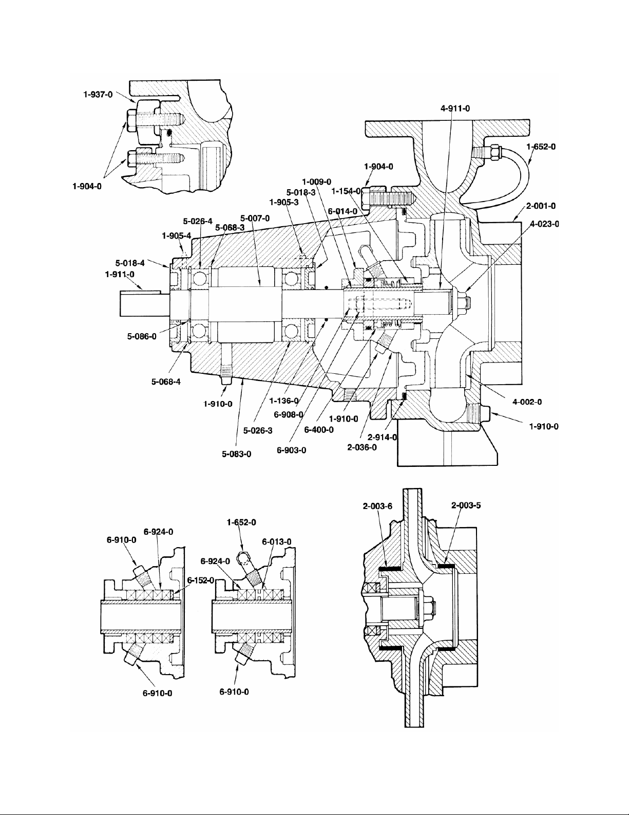
REPAIR PARTS LIST
Cat. No. Part Name Quantity Cat. No. Part Name Quantity
1-009-0 Shaft Sleeve 1 5-018-4 Bearing Cap, Outboard 1
1-136-0 Deflector 1 5-026-3 Bearing, Inboard 1
1-154-0 Spacer Sleeve 1 5-026-4 Bearing, Outboard 1
1-248-1 Frame Foot Assembly 1 5-068-3 Snap Ring, Inboard Bearing Housing 1
1-652-0 By-Pass Piping Kit 1 5-068-4 Snap Ring, Outboard Bearing Housing 1
Capscrews – Miscellaneous 81-904-0
With Lugs 5-086-0 Snap Ring, Shaft 1
1-905-3 Grease Fitting, Inboard 1 6-014-0 Gland 1
1-905-4 Grease Fitting Outboard 1 6-152-0 Ring Packing Base 1
Pipe Plugs 21-910-0
Without By-Pass 3
1-911-0 Key, Coupling 1 6-908-0 Gland Stud 2
2-001-0 Casing 1 Pipe Plug 16-910-0
2-036-0 Stuffing Box Cover 1
2-914-0 O-Ring, Casing Seal 1 Packing 5
2-937-0 Clamping Lug 8
4-002-0 Impeller 1
4-023-0 Impeller Nut 1
4-911-0 Key, Impeller 1
5-007-0 Shaft 1
5-018-3 Bearing Cap, Inboard 1
16
5-083-0 Frame 1
6-400-0 Mechanical Seal 1
6-903-0 Gland Nut 2
Without By-Pass 2
6-924-0
With Seal Cage 4
OPTIONAL COMPONENTS
1-652-0 By-Pass Piping Kit, Seal Cage 1
2-003-5 Wear Ring, Suction 1
2-003-6 Wear Ring, Stuffing Box 1
6-013-0 Seal Cage 1
19
Page 20

ORDERING PARTS
The pumps covered by this manual have
been designed and built with certain
rep storing parts. The st be manu
laceable wea
rec nventory of spa
ommended i re parts
dep
ends upon the installation and the
imp ontinued operatio
ortance of c n.
For rvice requiring a
critical se minimum of
“do e” a complete or “quick
wn tim change”
rotating element ended.
For service, with repairs
normal to be made in
the e following parts are
field, th
rec for stock.
ommended
x rings
1 set of bea
x g rings
1 set of wearin
x askets and O-rings
2 sets of g
x ical seals (complete)
2 mechan
Par
ts should be ordered as far in advance of
the sible since
ir use as pos circumstances
is recomm
DEAL R SER G
E VICIN
beyond the control of the company may
reduce existing stock. Not all parts are
cked and mu factured for
ord
er.
To pid handling of r
facilitate ra your order fo
spa parts, be sure to include the fol g
re lowin
info ation:
rm
1. r of the pump
Serial numbe .
2. h part.
Quantity of eac
3. mber of the pa
Catalog nu rt.
4. part.
Name of the
5. ed. (Parts d in
Material desir will be furnishe
original ma pecified as a
terials unless s
material change. All material substitutio
should be d the factory.)
iscussed with
each
ns
If trouble occurs that cannot be rectified,
contact your local AC Fire Pump
Systems representative. He will need the
following information in order to give you
assistance.
1. Complete nameplate data of pump and
motor.
2. Suction and discharge pipe pressure
gauge readings.
3. Ampere draw of the motor.
4. A sketch of the pump hook-up and piping.
Xylem Inc.
8200 N. Austin Avenue
Morton Grove, Illinois 60053
Phone: (847) 966-3700
Fax: (847) 965-8379
www.xyleminc.com/brands/acfirepump
AC Fire Pump is a trademark of Xylem Inc. or one of its subsidiaries.
© 2013 Xylem Inc. AC8652C May 2013
 Loading...