

Guarantee
UK: This fan is guaranteed against defects for 3 years from the date of purchase.
• Xpelair reserve the right to repair or replace the fan.
• Keep your purchase receipt.
• Any problems, contact the address below.
Outside UK: See International section below.
Technical Advice & Service
UK - Xpelair have a comprehensive range of services including:
• Free technical advice Help-Desk from Engineers on all aspects of ventilation.
• Free design service, quotations and site surveys.
Outside UK: See International section below.
Please ask for details on:
Tel +44 (0) 8709 000430
Fax +44 (0) 8709 000530
Also at the address below
Head Office – UK Sales Office and Spares
Applied Energy Products Ltd, Morley Way, Peterborough, PE2 9JJ, England
Tel: +44 (0) 1733 456789
Fax: +44 (0) 1733 310606
Sales/Spares Hotline: +44 (0) 8709 000420
Sales/Spares Faxline: +44 (0) 8709 000520
Web: http://www.xpelair.co.uk
Xpelair
Condensation Control Fans
♦ CF40 Pull Cord
♦ CF40TD Pull Cord/Timer
♦ CF40RSTD Remote Switched/Timer
Centrifugal Ducted Fans
♦ DX400 Remote Switched
♦ DX400PC Pull Cord
♦ DX400T Remote Switched/Timer
♦ DX400RS Remote Switched
Installation and maintenance instructions
Retain for future reference
GB
F
D
NL
N
S
I
GR
a
ES
International
Guarantee – Contact your local distributor or Xpelair direct
Technical advice and Service - Contact your local Xpelair distributor.
567-2077-01
Revision C
A
B
C
D
a
ES
Opciones auxiliares
A fin de agilizar y facilitar la
instalación es posible que su
instalación precise algunos de los
equipos auxiliares que aparecen
a continuación:
WD100 Conducto de pared
CFWG100 Rejilla de pared
XCT100 Trampa de
DGW/B Rejilla de puerta
SP100 Placa de espiga
XAA Adaptador de
VC10 Respiradero de
WT10 Juego de conducto
XF/FM Conducto plano
VK10 Juego de
KHWG Rejilla de pared
FD100 Conducto flexible
WDC5 Pinzas de tornillo
XCMK Juego para
XBP Persiana de tiro
EFT Adaptador de
PDXGF Filtro de grasas
Piezas de repuesto
A continuación se ofrece una
relación de piezas de repuesto
disponibles. Véase la última
página de este folleto para
obtener información sobre
pedidos:
41761SK Motor (DX400)
41762SK Motor (DX400PC)
41763SK Motor (CF40)
41764SK Conjunto de PCI
41765SK Conjunto de PCI
41766SK Conjunto de PCI
41767SK Conjunto de PCI
41768SK Conjunto de PCI
41774SK Cubierta frontal c/c
41771SK Moldura acústica
41772SK Conjunto de
condensación
para circulación de
aire
ladrillo ventilador
enfriamiento
de terminación
(metal / plástico)
(Plástico 234 x 29 /
Metal 230 x 25)
ventilación de
pared
(negra)
sinfín
montaje en techo
posterior en línea
juego de
terminación de
ajuste fácil
(DX400T)
(DX400RS)
(CF40)
(CF40TD)
(CF40RSTD)
difusor
(DX400/CF40)
(Toda la gama)
cordón (Toda la
gama)

N S I GR
Tilbehør
For at installeringen skal være
hurtig og enkel kan det hende at
installasjonen din trenger noe av
tilleggsutstyret angitt nedenfor:
WD100 Veggkanal
CFWG100 Veggrist
XCT100 Kondensfanger
DGW/B Deksel med rist for
SP100 Tapplate
XAA Perforert teglstein-
VC10 Ventilhette
WT10 Utgangskanalsett
XF/FM Flatt kanalsystem
VK10 Veggventilsett
KHWG Veggrist (svart)
FD100 Fleksibel kanal
WDC5 Snekkedrifts-
XCMK Ta kmonteringssett
XBP Innebygget
EFT Adapter til
PDXGF Fettfilter
Reservedeler
På listen nedenfor finner du noen
av de tilgjengelige reservedelene.
Se baksiden av dette heftet for
opplysninger om bestilling:
41761SK Motor (DX400)
41762SK Motor (DX400PC)
41763SK Motor (CF40)
41764SK PCB-sett (DX400T)
41765SK PCB-sett
41766SK PCB-sett (CF40)
41767SK PCB-sett
41768SK PCB-sett
41774SK Frontdeksel
41771SK Innfatningsforming
41772SK Drasnormontering
luftsirkulasjon
adapter
(Metall/plast)
(Plast 234 x 29/
metall 230 x 25)
klemme
uttrekkspjeld på
baksiden
utgangssett for
enkel montering
(DX400RS)
(CF40TD)
(CF40RSTD)
m/skjerm
(hele utvalget)
(hele utvalget)
Tillbehörsalternativ
För att installationen ska gå så
snabbt och enkelt som möjligt kan
det hända att du behöver några
av tillbehören som listas nedan:
WD100 Väggtrumma
CFWG100 Väggaller
XCT100 Kondensavskiljare
DGB/W Luftombytesgaller
SP100 Plåt för tappar
XAA Adapter (Air Brick
VC10 Ventilationshuv
WT10 Utrustning för
XF/FM Platt trumma
VK10 Sats för
KHWG Väggaller (svart)
FD100 Flexibel trumma
WDC5 Skruvväxel-
XCMK Sats för
XBP Bakre draglucka
EFT Lättmonterad
PDXGF Fettfilter
Reservdelar
Här listas några av de reservdelar
som finns tillgängliga.
Beställningsinformation finns på
baksidan av det här häftet.
41761SK Motor (DX400)
41762SK Motor (DX400PC)
41763SK Motor (CF40)
41764SK PCB Assy
41765SK PCB Assy
41766SK PCB Assy (CF40)
41767SK PCB Assy
41768SK PCB Assy
41774SK Frontpanel
41771SK Rammontering
41772SK Snörmontering
till lucka
Adaptor)
trummans ände
(plast 234 x 29/
metall 230 x 25)
väggventilation
sklämmor
takmontering
adaptersats för
trummans ände
(DX400T)
(DX400RS)
(CD40TD)
(CF40RSTD)
tak/vägg platta
(DX400/CF40)
(hela sortimentet)
(hela sortimentet)
Accessori opzionali
Per velocizzare e facilitare
l'installazione, possono essere
necessari alcuni degli accessori
elencati di seguito:
WD100 Tubo da muro
CFWG100 Griglia da muro
XCT100 Separatore di
DGW/B Griglia sullo
SP100 Piastra giunto
XAA Adattatore per
VC10 Coperchio di sfiato
WT10 Kit tubo di
XF/FM Tubo piatto
VK10 Kit di sfiato a
KHWG Griglia da muro
FD100 Tubo flessibile
WDC5 Clip con vite senza
XCMK Kit per montaggio
XBP Otturatore d'aria
EFT Adattatore per kit
PDXGF Filtro del grasso
Parti di ricambio
Di seguito viene fornita una lista
di parti di ricambio disponibili. Per
informazioni sulle ordinazioni
vedere l'ultima pagina del
presente manuale:
41761SK Motore (DX400)
41762SK Motore (DX400PC)
41763SK Motore (CF40)
41764SK Gruppo PCB
41765SK Gruppo PCB
41766SK Gruppo PCB
41767SK Gruppo PCB
41768SK Gruppo PCB
41774SK Coperchio
41771SK Telaio (Intera
41772SK Gruppo interruttore
condensa
sportello per il
ricambio aria
mattone forato
terminazione
(Metallo / Plastica)
(Plastica 234x29/
Metallo 230x25 )
parete
(Nera)
fine
sul soffitto
posteriore in linea
finale easy fit
(DX400T)
(DX400RS)
(CF40)
(CF40TD)
(CF40RSTD)
anteriore
con/senza piastra
di protezione
(DX400/CF40)
gamma)
a cordicella (Intera
gamma)
Συµπληρωµατικές Επιλογές
Γι α γρήγορη και εύκολη
εγκατάσταση, η εγκατάσταση
σασ µπορεί να χρειαστεί µερικά
απ τα Συµπληρωµατικά που
αναφέρονται πιο κάτω:
WD100 Αγωγσ τοίχου
CFWG100 Κιγκλίδωµα τοίχου
XCT100 Ατµοπαγίδα
DGW/B Κιγκλίδωµα πρτασ
SP100 Πλάκα βύσµατοσ
XAA Προσαρµογέασ
VC10 Κάλυµµα
WT10 Σύνολο αγωγού
XF/FM Επίπεδοσ αγωγσ
VK10 Σύνολο αεραγωγού
KHWG Κιγκλίδωµα τοίχου
FD100 Εύκαµπτοσ αγωγσ
WDC5 Κλιπ οφιοειδούσ
XCMK Σύνολο
XBP Φράχτησ
EFT Σύνολο
PDXGF Φίλτρο λιπαρών
Ανταλλακτικά
Πιο κάτω αναφέρονται µερικά
απ τα διαθέσιµα
ανταλλακτικά. Συµβουλευθείτε
την πίσω ψη του παρντοσ
φυλλαδίου για λεπτοµέρειεσ
παραγγελίασ:
41761SK Μοτέρ (DX400)
41762SK Μοτέρ (DX400PC)
41763SK Μοτέρ (CF40)
41764SK Σύνολο PCB
41765SK Σύνολο PCB
41766SK Σύνολο PCB (CF40)
41767SK Σύνολο PCB
41768SK Σύνολο PCB
41774SK Μπροστιν
41771SK Χυτ πλαίσιο
41772SK Σύνολο κορδονιού
ανανέωσησ αέρα
τούβλου αέρα
αεραγωγού
τερµατισµού
(πλαστικ/µέταλλο)
(πλαστικ 234 χ 29 /
µέταλλο 230 χ 25)
τοίχου
(µαύρο)
κίνησησ
τοποθέτησησ σε
ταβάνι
οπισθοδροµικού
ρεύµατοσ in-line
τερµατισµού
εύκολησ
εφαρµογήσ
ουσιών
(DX400T)
(DX400RS)
(CF40TD)
(CF40RSTD)
κάλυµµα
συνοδευµενο απ
εκτροπέα
(DX400/CF40)
(ολκληρη σειρά)
τραβήγµατοσ
(ολκληρη σειρά)
E
Ensemble CCI
(Carte de Circuit
Imprimé)
F
G
GB
Ancillary Options
For speed and ease of
Installation, your installation may
require some of the Ancillaries
listed below:
WD100 Wall Duct
CFWG100 Wall Grille
XCT100 Condensation Trap
DGW/B Air Replacement
SP100 Spigot Plate
Door Grille
XAA Air Brick Adaptor
VC10 Vent Cowl
WT10 Termination Ducting
XF/FM Flat Ducting
Kit
(Plastic / Metal)
(Plastic 234x29
VK10 Wall Vent Kit
/ Metal 230x25)
KHWG Wall Grille (Black)
FD100 Flexible Ducting
WDC5 Worm Drive Clips
XCMK Ceiling Mounting Kit
XBP In-Line Back
EFT Easy Fit
Draught Shutter
Termination Kit
PDXGF Grease Filter
Adaptor
Spares
Listed below are some of the
spares available. See back-page
of this booklet for ordering details:
41761SK Motor (DX400)
41762SK Motor (DX400PC)
41763SK Motor (CF40)
41764SK PCB Assy
41765SK PCB Assy
41766SK PCB Assy (CF40)
(DX400T)
(DX400RS)
41767SK PCB Assy
41768SK PCB Assy
41774SK Front Cover c/w
(CF40TD)
(CF40RSTD)
Baffle
41771SK Surround Moulding
41772SK Pull-Cord Assembly
(DX400/CF40)
(Entire Range)
(Entire Range)
Options Auxiliaires
Pour que l'installation soit plus
rapide et plus facile, il peut être
nécessaire d'utiliser les options
auxiliaires indiquées ci-dessous.
WD100 Gaine Murale
CFWG100 Grille Murale
XCT100 Collecteur de
DGW/B Grille de porte de
SP100 Plaque de
XAA Adaptateur de
VC10 Capot d'Aération
WT10 Kit de Gaine de
XF/FM 6. Gaîne plate
VK10 Kit d'Aération
KHWG Grille Murale
FD100 Gaine Souple
WDC5 Clips à Vis Sans
XCMK Kit de Montage au
XBP Volet de
EFT Kit d'Installation
PDXGF Filtre de Graisse
Rechanges
On indique ci-dessous quelquesunes des rechanges disponibles.
Voir la dernière page de ce
manuel pour les informations en
vue de passer commande :
41761SK Moteur (DX400)
41762SK Moteur (DX400PC)
41763SK Moteur (CF40)
41764SK Ensemble CCI
41765SK
41766SK Ensemble CCI
41767SK Ensemble CCI
41768SK Ensemble CCI
41774SK Couvercle Avant
41771SK Encadrement
41772SK Ensemble Cordon
F D NL
Condensation
renouvellement de
l’air
Centrage
Brique d'Air
Ter m inaison
(Plastique/Métal)
(Plastique 234 x 29
/ Métal 230 x 35)
Murale
(Noire)
Fin
Plafond
Refoulement en
Ligne
Facile de
Ter m inaison
(Carte de Circuit
Imprimé) (DX400T)
(DX400RS)
(Carte de Circuit
Imprimé) (CF40)
(Carte de Circuit
Imprimé) (CF40TD)
(Carte de Circuit
Imprimé)
(CF40RSTD)
avec Chicane
(DX400/CF40)
Moulé (Gamme
Complète)
de Tirage (Gamme
Complète)
Zusatzteile
Für eine schnellere und leichtere
Installation werden
möglicherweise einige der unten
aufgeführten Zusatzteile benötigt:
WD100 Wandkanal
CFWG100 Wandgitter
XCT100 Kondensatablauf
DGW/B Luftaustausch-
SP100 Rohranschluss-
XAA Hohlziegeladapter
VC10 Lüftungskappe
WT10 Endkanal-
XF/FM Flachkanal (Metall
VK10 Wandentlüftung-
KHWG Wandgitter
FD100 Biegsamer
WDC5 Schnecken-
XCMK Decken-
XBP Rückzugsklappe
EFT Schnellmontagesatz
PDXGF Fettfilter
Ersatzteile
Unten finden Sie einige der
verfügbaren Ersatzteile aufgelistet
Bestellangaben finden Sie auf der
Rückseite dieser Broschüre:
41761SK Motor (DX400)
41762SK Motor (DX400PC)
41763SK Motor (CF40)
41764SK Leiterplatte
41765SK Leiterplatte
41766SK Leiterplatte (CF40)
41767SK Leiterplatte
41768SK Leiterplatte
41774SK Vorderabdeckung
41771SK Einfassungsteil
41772SK Zugschnur
türgitter
stutzenplatte
montagesatz
/ Plastik) (Plastik
234 x 29 / Metall
230 x 25)
smontagesatz
(schwarz)
Leitungskanal
gewinde-Schellen
montagesatz
Adapter für
Kanalende
(DX400T):
(DX400RS)
(CF40TD)
(CF40RSTD)
mit Leitblech
(DX400/CF40)
(Gesamtes
Sortiment)
(Gesamtes
Sortiment)
Afwerkingsopties
Om de montage sneller en
gemakkelijker te laten verlopen,
heeft u eventueel volgende
afwerkingsmiddelen nodig.
WD100 Muurdoorvoer
CFWG100 Muurrooster
XCT100 Condensaatvanger
DGW/B Deurrooster
SP100 Luchtinlaatplaat
XAA Gatensteenadapter
VC10 Luchtopeningskap
WT10 Afsluitkanaalkit
XF/FM Plat kanaal
VK10 Muuropeningskit
KHWG Muurrooster
FD100 Flexibel kanaal
WDC5 Wormklemmen
XCMK Plafondmontagekit
XBP Tochtsluiter
EFT Easy Fit
PDXGF Vetfilter
Wisselstukken
Hierna vindt u enkele leverbare
wisselstukken. De
bestelgegevens vindt u op de
achterflap van deze brochure:
41761SK Motor (DX400)
41762SK Motor (DX400PC)
41763SK Motor (CF40)
41764SK Print (DX400T)
41765SK Print (DX400RS)
41766SK Print (CF40)
41767SK Print (CF40TD)
41768SK Print (CF40RSTD)
41774SK Schermplaat met
41771SK Montageplaat-
41772SK Trekkoordsysteem
luchtverversing
(plastic / metaal)
(plastic 234 x 29 /
metaal 230 x 25)
(zwart)
afsluitadapter
schot
(DX400/CF40)
sierstrip (volledig
gamma)
(volledig gamma)
Cableado de las conexiones eléctricas
1. Aísle el suministro eléctrico y retire todos los
fusibles. La caja de terminales es apta para cables
de hasta 2.5mm
2. Utilice un conmutador de aislamiento de dos polos con
una separación mínima de contacto de 3 mm en
ambos polos.
3. Utilice un cable de 3 almas o 4 almas de la
clasificación correcta, dependiendo de la aplicación.
4. Cablee el ventilador como se muestra en la Fig.
utilice la abrazadera para cables que se proporciona
a fin de asegurar el cable. Compruebe el modelo de
ventilador con el diagrama.
velocidad) / “LL” = Vivo (Baja velocidad).
5. Vuelva a colocar la tapa de la caja de terminales
apriete los tornillos de sujeción.
6. Consulte el apartado
utilizar otros ajustes que no sean los ajustados en
fábrica.
7. Vuelva a colocar la cubierta frontal
8. Conecte el cable del conmutador de aislamiento al
cableado del suministro eléctrico y vuelva a
comprobar la instalación.
9. Antes de volver a conectar la electricidad, instale los
fusibles.
10. Para circuitos de cableado fijo, el fusible de seguridad
para el aparato no debe superar 5A.
Ajustes del usuario
Antes de llevar a cabo cualquier ajuste, aísle el
ventilador del suministro eléctrico de la red,
compruebe las especificaciones que se ofrecen
seguidamente, a fin de ver qué características son
aplicables al modelo de ventilador.
1. Retire la cubierta frontal y vuélvala a colocar después
del ajuste .
DX400 / DX400PC / DX400RS
Estos modelos de ventiladores no pueden ser ajustados
por el usuario.
DX400T
1. 1. El periodo de rebase del temporizador puede
ajustarse entre aproximadamente 30 segundos y 20
minutos. Utilice un destornillador de electricista y gire
el tornillo “T” (Fig.
incrementar el tiempo o hacia la izquierda para
reducirlo. (El ajuste de fábrica es de
aproximadamente 10 minutos).
CF40
1. El ajuste de humedad puede ajustarse entre
aproximadamente 50% y 90% de humedad relativa.
Utilice un destornillador de electricista u gire el tornillo
“RH” (Fig.
ajuste de humedad relativa y hacia la izquierda para
reducirla. (Nota: el ventilador es más sensible a 50%
de HR que a 90%).
CF40TD / CF40RSTD
1. El periodo de rebase del temporizador puede
ajustarse entre aproximadamente 30 segundos y 20
minutos. Utilice un destornillador de electricista y gire
el tornillo “T” (Fig.
incrementar el tiempo o hacia la izquierda para
reducirlo. (El ajuste de fábrica es de
aproximadamente 10 minutos).
2. El ajuste de humedad puede ajustarse entre
aproximadamente 50% y 90% de humedad relativa.
Utilice un destornillador de electricista u gire el tornillo
“RH” (Fig.
ajuste de humedad relativa y hacia la izquierda para
reducirla. (Nota: el ventilador es más sensible a 50%
de HR que a 90%).
Uso del ventilador
DX400
Ponga en funcionamiento el ventilador utilizando el
interruptor de encendido / apagado externo. Repita el
procedimiento para apagarlo. La velocidad del ventilador
está preajustada por el instalador, bien a velocidad rápida
o lenta. (Si se ha instalado un inversor de corriente
2
.
DX400: “LH” = Vivo (Alta
“Ajustes del usuario” si desea
2 (Fig. C).
C)
D), hacia la derecha para
D) hacia la derecha para incrementar el
D), hacia la derecha para
D) hacia la derecha para incrementar el
entonces el usuario puede cambiar la velocidad de rápida
a lenta.)
DX400PC
Secuencia de funcionamiento del cordón:
Ventilador apagado (luz apagada)
Tire del cordón una vez, el ventilador se pone en
funcionamiento en velocidad rápida (“la luz II” está
encendida – alta intensidad)
Tire del cordón otra vez, el ventilador se pone en
funcionamiento en velocidad lenta (“la luz II” está
F y
encendida – baja intensidad)
Tire del cordón otra vez, el ventilador se apaga (luz
apagada)
El instalador puede ajustar un interruptor interno a fin de
ofrecer extracción continua de fondo cuando está
5 y
“apagado”.
DX400T
Accione el ventilador utilizando el interruptor de encendido
/ apagado.
Cuando se encienda el interruptor, el ventilador funcionará
a velocidad rápida.
Cuando se apague el interruptor, el ventilador continúa
funcionando a velocidad lenta durante el periodo de
rebase del temporizador ajustable (“la luz I” está
encendida e indica que el ventilador está funcionando en
modo manual)
El instalador puede ajustar un interruptor interno a fin de
ofrecer extracción continua de fondo cuando está
“apagado”.
Función de demora de puesta en marcha encendida o
apagada.
Esta función la ajusta el instalador a fin de ofrecer una
demora de puesta en marcha de 2 minutos cuando se
enciende el ventilador utilizando el interruptor de
encendido / apagado externo.
DX400RS
Accione el ventilador utilizando el interruptor de encendido
/ apagado.
Seleccione velocidad rápida o lenta utilizando el
interruptor remoto. El instalador puede ajustar un
interruptor interno a fin de ofrecer extracción continua de
fondo cuando está “apagado”.
La “luz I” superior está encendida a alta densidad cuando
el ventilador funciona a velocidad rápida, y a intensidad
baja cuando el ventilador funciona a velocidad lenta. La
luz se apaga cuando el ventilador está apagado o
funciona a extracción lenta.
CF40 / CF40TD
Funcionamiento conmutado
El ventilador puede cablearse con un interruptor de
encendido / apagado separado. El ventilador funciona a la
velocidad de condensación cuando se enciende. La “luz I”
superior está encendida cuando se enciende el interruptor
de encendido / apagado separado. Cuando está apagado,
el ventilador continuará funcionando si el nivel de
humedad es superior al establecido por el tornillo de
ajuste “RH”. CF40TD solamente: Cuando se apaga, el
ventilador continúa funcionando durante el periodo de
rebase del temporizador ajustable.
Funcionamiento de la condensación
El ventilador se pine en funcionamiento a la velocidad de
control de condensación cuando la humedad relativa
supera el nivel establecido y se apaga cuando la
humedad relativa baja.
Funcionamiento de refuerzo
Secuencia del cordón:
Funcionamiento de condensación automático (Ambas
luces apagadas)
Tire del cordón una vez, el ventilador se pone en
funcionamiento en velocidad rápida (“luz II” inferior está
encendida – alta intensidad).
Tire del cordón otra vez, el ventilador se pone en
funcionamiento en la velocidad de condensación manual
(“luz II” inferior está encendida – baja intensidad)
Tire del cordón otra vez, el ventilador funciona a velocidad
de condensación automática (ambas luces apagadas)
Función lenta encendida o apagada
Esta función la ajusta el instalador a fin de ofrecer
extracción de fondo continua, cuando el nivel de humedad
es inferior al establecido por el tornillo de ajuste “RH” y el
ventilador está en el modo de condensación automático.
CF40TD solamente
Función de demora de puesta en marcha encendida o
apagada
Esta función la ajusta el instalador a fin de ofrecer una
demora de puesta en marcha de 2 minutos cuando el
ventilador se enciende utilizando un interruptor de
encendido / apagado separado.
CF40RSTD
Funcionamiento de la condensación
El ventilador funciona a la velocidad de control de la
condensación, cuando la humedad relativa supera el nivel
establecido, y se apaga cuando baja la humedad.
Funcionamiento de refuerzo
Accione el ventilador utilizando el interruptor de encendido
/ apagado. Seleccione velocidad rápida o lenta utilizando
el interruptor remoto. Cuando está apagado, el ventilador
continúa funcionando durante el periodo de rebase
ajustable. El instalador puede ajustar un interruptor interno
a fin de que el ventilador continúe ofreciendo extracción
de fondo continua cuando esté “Apagado”. La “luz I”
superior está encendida a intensidad alta cuando el
ventilador está funcionando a velocidad rápida, y a
intensidad baja cuando el ventilador está funcionando a
velocidad lenta. La luz está apagada cuando el ventilador
está Apagado o funcionando en el modo de extracción
lenta.
Limpieza
1. Antes de limpiar el ventilador, aísle el suministro
eléctrico de la red.
2. Limpie únicamente la superficie exterior del ventilador,
utilizando un paño húmedo sin pelusas.
3. No utilice detergentes fuertes, disolventes ni
limpiadores químicos.
4. Deje que el ventilador se seque completamente antes
de volver a usarlo.
5. Aparte de la limpieza, el ventilador no precisa ningún
otro mantenimiento.
Clave
Véase el diagrama E
1. Placa deflectora
2. Cubierta frontal
3. Impulsor
4. Tornillos de sujeción
5. Tapa de terminales
6. Caja del ventilador
7. Espiga circular
8. Tornillos de abrazadera y tirafondos – 3 x
9. Abrazaderas del cuerpo del ventilador – 3 x
10. Perímetro
11. Tornillos de techo 25 mm de largo 4 x (Diagrama
B)
12. Cinta de espuma
PARA EL BENEFICIO DEL USUARIO DEJE ESTE
FOLLETO CON EL VENTILADOR.
GB
IMPORTANT
1. READ ALL THESE INSTRUCTIONS & WARNINGS FULLY BEFORE COMMENCING INSTALLATION.
2. INSTALLATIONS AND WIRING MUST CONFORM TO CURRENT IEE REGULATIONS (UK), LOCAL OR APPROPRIATE
REGULATIONS (OTHER COUNTRIES). IT IS THE INSTALLER’S RESPONSIBILITY TO ENSURE THAT THE APPROPRIATE
BUILDING CODES OF PRACTICE ARE ADHERED TO.
3. A QUALIFIED ELECTRICIAN MUST SUPERVISE ALL INSTALLATIONS.
4. THESE APPLIANCES ARE INTENDED FOR CONNECTION TO FIXED WIRING.
5. CHECK THAT THE ELECTRICAL RATING SHOWN ON THE FAN MATCHES THE MAINS SUPPLY.
6. W
ARNING: THESE APPLIANCES MUST BE EARTHED.
7. SITE AWAY FROM DIRECT SOURCES OF HEAT (I.E.: GAS COOKERS OR EYE-LEVEL GRILLS) AND NOT WHERE
AMBIENT TEMPERATURES ARE LIKELY TO EXCEED 50
8. WHEN THE FAN IS INSTALLED IN A ROOM CONTAINING A FUEL BURNING APPLIANCE, THE INSTALLER MUST ENSURE
THAT AIR REPLACEMENT IS ADEQUATE FOR BOTH THE FAN AND THE FUEL BURNING APPLIANCE.
9. ENSURE THAT ALL RELEVANT SAFETY PRECAUTIONS (CORRECT EYE PROTECTION AND PROTECTIVE CLOTHING
ETC) ARE TAKEN WHEN INSTALLING, OPERATING AND MAINTAINING THIS FAN.
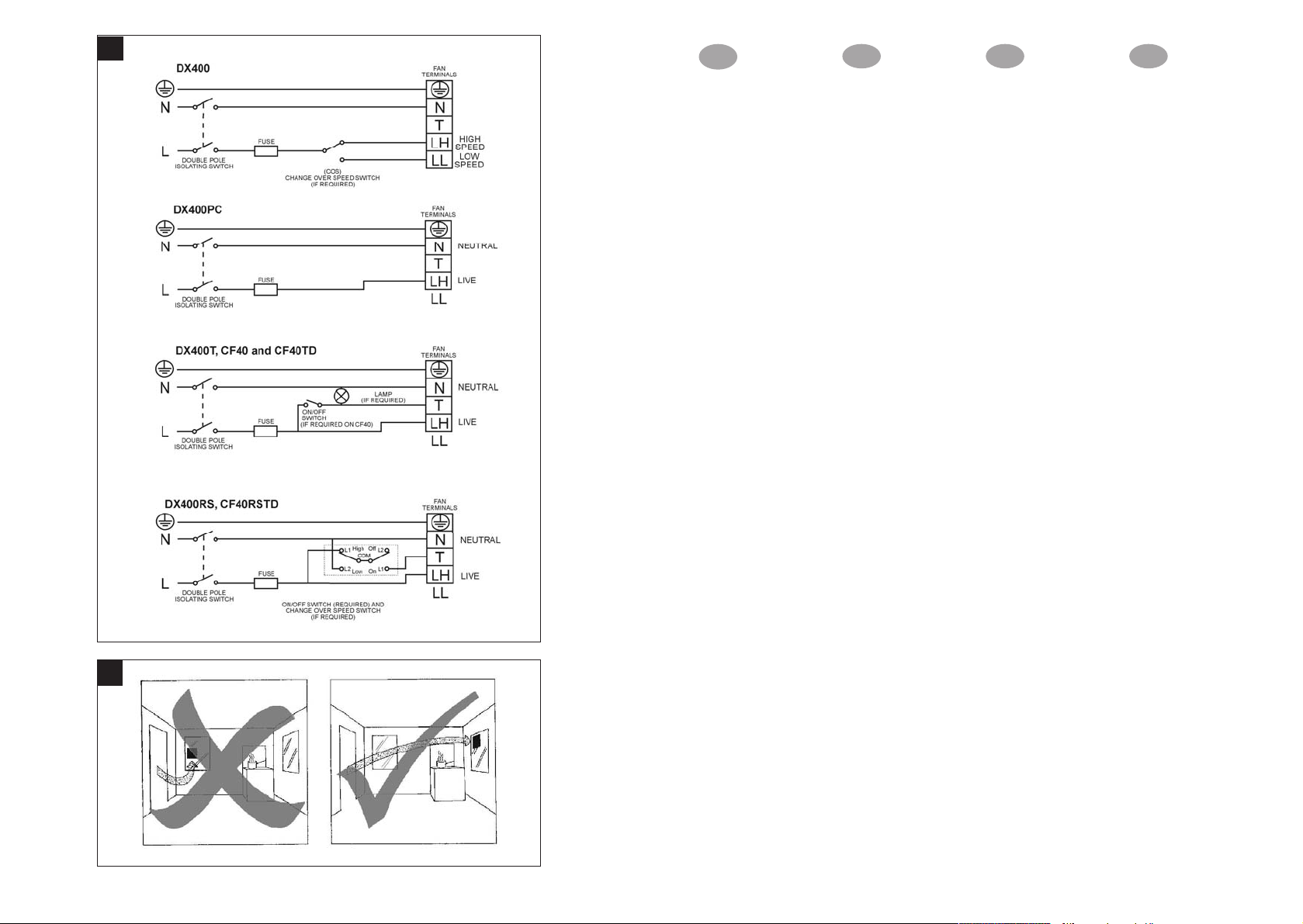
10. GENERAL GUIDANCE FOR SITING THE FAN SEE “FIG. G”. ALWAYS SITE FAN AS HIGH AS POSSIBLE
11. IF ANY SECTION OF THE DUCTWORK IS POSITIONED HIGHER THAN THE FAN ACONDENSATION TRAP (XCT100) MUST
BE FITTED AS CLOSE AS POSSIBLE TO THE FAN.
12. THE APPLIANCE IS NOT INTENDED FOR USE BY YOUNG CHILDREN OR INFIRM PERSONS. YOUNG CHILDREN
SHOULD BE SUPERVISED TO ENSURE THEY DO NOT PLAY WITH THE APPLIANCE.
For speed and ease of Installation, your
installation may require some of the Ancillaries
indicated in “Ancillary Options”.
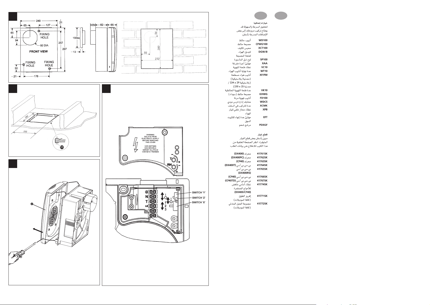
If installing on a wall (surface mounting)
1. Mark on the wall the centre of the duct hole A.
2. Use this centre to cut an opening through the wall
117mm diameter, with a slight fall to the exterior.
3. Fit the wall tube, not supplied, and mortar into
place.
If installing in a wall (flush mounting)
1. Mark on the wall the centre of the duct hole A,
and drill a pilot hole through both walls.
2. Use the centre to mark a rectangular hole for the
inner wall using the dimensions A.
3. Cut the rectangular hole through the inner wall.
4. Go outside and cut a 117mm diameter hole in the
outer wall using the small hole as the centre.
5. Measure the wall thickness.
Cut the wall tube (WD100), not supplied, so that it
is 85mm less than the wall thickness.
If installing on a ceiling (surface mounting)
This method requires a space above the ceiling, such
as a loft or attic, to provide access for 100mm internal
diameter ducting, or a minimum 70mm void using flat
ducting.
1. Mark on the ceiling the centre of the duct hole A,
avoiding ceiling joists and buried cables etc..
2. Cut a 117mm diameter hole using the marked
centre.
If installing in a ceiling (flush mounting)
For 100mm diameter ducting:
This method requires a space above the ceiling, such
as a loft or attic, to provide access for 100mm internal
diameter ducting.
1. Mark a rectangular hole using the dimensions B.
2. Cut the hole, avoiding ceiling joists and buried
cables etc.
For flat ducting:
• This fan can be installed within a 140mm void with
the circular spigot
7.
Preparing the fan for installation
1. Remove the front cover 2 (Fig.C)
2. Fit the foam tape !™ supplied around the circular
7 (Fig.E).
spigot
3. Remove the electrical cover 5 (Fig.E).
Setting the condensation speed
CF40 / CF40TD / CF40RSTD Only (Fig.D)
4. The correct condensation control speed should be
selected to suit the room size in which the fan is to
be installed. Slide the switch X to the required
position. Please note that the fan is factory set to
“Position 2”.
5. Switch Position Size / Room Volume (m3)
1 Large (54 and above)
2 Medium (30 – 54)
3Small (less than 30)
Setting the trickle speed
All models except DX400 (Fig.D)
6. The fan can be set so that it provides constant
trickle extraction. Slide the switch Y to the
required position. Please note that the fan is factory
set to “Position 0”.
Switch Position Setting
0Trickle extraction OFF
ITrickle extraction ON
Setting the time delay start
DX400T / CF40TD Only (Fig. D)
7. The fan can be set so that there is a 2-minute
delayed start to its operation when used with an
external on/off switch. Slide the switch Z to the
required position. Please note that the fan is factory
set to “Position 0”.
8. Switch Position Setting
0Time delay start OFF
ITime delay start ON
Mounting the fan on a wall or ceiling (surface
mounting)
1. Place the ducting into the hole and align to the
required position. If wall mounting, ensure that the
ducting slopes down and away from the fan
2. Mark the positions of the three fixing holes A in
Fan box 6 (Fig.E).
3. If wall mounting, drill three holes 5.5mm diameter
for wall plugs (supplied). If ceiling mounting B,
use appropriate fasteners (not supplied).
4. Cut out the cable inlet hole, if required, in the
surround
surround 0 over the fan box 6.
5. Pass the electrical cables into the fan box 6
through the rear cable inlet hole and surround,
and re-fit the cable grommet. Ensure that cable
grommet is in place and a tight fit.
6. Offer the fan box 6 up to the wall or ceiling.
Ensure the circular spigot 7 enters the ducting.
7. Fix the fan box 6 to the wall using screws 8 or to
the ceiling using appropriate fasteners (not
supplied).
O
C.
If mounting in a wall (flush mounting)
The surround 0 is not required. Fit the ducting to the
circular spigot 7.
If the hole size is as recommended:
1. Assemble the three fan body clamps 9 to the fan
2. Slit the cable grommet. Pass the electrical cables
3. Offer the fan box 6 up to the wall. Ensure the
4. Tighten up the three screws 8 until the fan is
If the hole size is larger than recommended i.e.:
larger than the flange on the fan box 6 (Mostly
relating to “retro-fit” installations):
1. The fan body clamps ARE NOT suitable.
2. Offer the fan box 6 up to the wall. Ensure the
3. Screw the fan box 6 to the wooden frame using
If mounting in a ceiling (flush mounting)
1. The surround 0 is not required.
2. Insert the fan box 6 into the hole and mark four
3. Remove the fan box 6 from ceiling and fit the four
4. Drill 4 pilot holes into the ceiling through the hole
5. Fit the ducting to the circular spigot 7.
6. Offer the fan box
0 and slit the cable grommet. Slide the
7. Slit the cable grommet. Pass the electrical cable
8. Using the screws !¡ (Fig.B), fix the fan box
Terminating the ducting
Fit the outer grille to the outer wall. For ceiling
mounting, use appropriate ancillaries (not supplied).
box 6 using screws 8.
into the fan box 6 through the cable inlet hole and
cable grommet.
Ensure cable grommet is in place and a tight
fit.
circular spigot 7 enters the ducting.
clamped to the inner wall. The fan body clamps 9
will rotate to an automatic stop position. DO NOT
OVERTIGHTEN.
Construct a wooden frame of INTERNAL
dimensions 232 x 280mm. Depth should be at
least 50mm. Fit the wooden frame into the internal
wall and make good the hole.
circular spigot 7 enters the ducting.
the slots in the flange (screws not supplied).
positions using the slots in the flange B.
ceiling clips (supplied) over the edge of the hole,
so that the clips align with the marks on the ceiling
B.
of each clip, ensuring not to damage the clip, and
fit the clips ensuring correct alignment.
6 up to the ceiling.
into the fan box 6 through the front cable inlet
hole.
Ensure cable grommet is in place and a tight
fit.
flange to the ceiling clips.

Wire the electrical connections
1. Isolate the electricity supply and remove all
fuses.
The terminal block will accept cable up to
2
.
2.5mm
2. Use a double-pole isolating switch with a minimum
contact gap of 3mm in both poles.
3. Use suitably rated 3-core or 4-core cable
dependant on application.
4. Wire the fan as shown in
clamp provided to secure the cable. Check fan
model to diagram.
Speed) / “LL” = Live (Low Speed)
5. Replace the terminal cover
retaining screws.
6. See section on “
use settings other than those that have been
factory set.
7. Refit the front cover
8. Connect the cable from the isolating switch to
electrical supply wiring, and re-check installation.
9. Refit fuses before turning on electricity supply.
10. For fixed wiring circuits, the protective fuse for the
appliance must not exceed 5A.
F and use the cable
DX400: “LH” = Live (High
5 and fasten the
User adjustments” if you wish to
2 (Fig.C).
User adjustments
Before making any adjustments, isolate the fan
completely from the mains supply, check
specification below to see which features apply to
your fan.
1. Remove the front cover and replace after
adjustment (Fig.
C)
DX400 / DX400PC / DX400RS
There are no user adjustments for these fans.
DX400T
1. The timer over-run period can be adjusted
between approximately 30 seconds and 20
minutes. Use an electrician’s screwdriver and turn
screw “T” (Fig.
anti-clockwise to decrease. (Factory preset to
approximately 10 minutes)
D), clockwise to increase time,
CF40
1. The humidity setting is adjustable between
approximately 50% and 90% relative humidity.
Use an electrician’s screwdriver, and turn screw
D), clockwise to increase the relative
“RH” (Fig.
humidity setting and anti-clockwise to decrease.
(Note: the fan is more sensitive at 50% RH than
at 90%).
CF40TD / CF40RSTD
1. The timer over-run period can be adjusted
between approximately 30 seconds and 20
minutes. Use an electrician’s screwdriver and turn
screw “T” (Fig.
anti-clockwise to decrease.
2. The humidity setting is adjustable between
approximately 50% and 90% relative humidity.
Use an electrician’s screwdriver, and turn screw
“RH” (Fig.
humidity setting and anti-clockwise to decrease.
(Note: the fan is more sensitive at 50% RH than
at 90%).
D), clockwise to increase time,
D), clockwise to increase the relative
Using the fan
DX400
Operate the fan using the external on/off switch.
Repeat to switch off. The fan speed is pre-set by the
installer to either high or low speed. (If a change
over switch has been installed then the user can
switch between high speed and low speed.)
DX400PC
Pull Cord operation sequence:
Fan off (light off)
Pull cord once, fan operates on high speed (“light II”
is lit - high intensity)
Pull cord again, fan operates on low speed (“light II”
is lit - low intensity)
Pull cord again, fan off (light off)
An internal switch can be installer set to provide
continuous background extraction in the ‘Off’ state.
DX400T
Operate the fan using the on/off switch.
When the switch is turned on, the fan will operate at
High Speed.
When the switch is turned off, the fan continues to
operate at low speed for the adjustable timer over-run
period (“light I” is lit indicating fan is operating in
manual mode)
An internal switch can be installer set to provide
continuous background extraction in the ‘Off’ state.
Time delay start feature on or off.
This is set by the installer to provide a 2-minute time
delay start when the fan is switched on using the
external on/off switch.
DX400RS
Operate the fan using the on/off switch.
Select high or low speed using the remote switch.
An internal switch can be installer set to provide
continuous background extraction in the ‘Off’ state.
The Top Light “I” is lit at high intensity when the fan
runs at High Speed, and at low intensity when
running at Low speed. The light is out when the fan is
Off or running at Trickle extraction.
CF40 / CF40TD
Switched Operation
The fan can be wired with a separate on/off switch.
Fan operates at condensation speed when switched
on. Top “Light I” is lit when the separate on/off switch
is switched on. When switched off, the fan will
continue to operate if the humidity level is above that
set by adjusting screw “RH”. CF40TD only: When
switched off, the fan continues to operate for the
adjustable timer over-run period.
Condensation Operation
The fan operates at condensation control speed,
when the relative humidity exceeds the set level, and
turns off when the humidity drops.
Boost Operation
Pull Cord sequence:
Automatic condensation operation (Both lights off)
Pull Cord once, fan operates on high speed (bottom
“light II” is on - High intensity).
Pull cord again, fan operates on manual
condensation speed (bottom “light II” is on - low
intensity)
Pull cord again, fan operates at automatic
condensation speed (both lights off)
Trickle feature on or off
This is set by the installer to provide continuous
background extraction, when the humidity level is
below that set by adjusting screw “RH” and the fan is
in automatic condensation mode.
CF40TD only
Time delay start feature on or off
This is set by the installer to provide a 2-minute time
delay start when the fan is switched on using a
separate on/off switch.
CF40RSTD
Condensation Operation
The fan operates at condensation control speed,
when the relative humidity exceeds the set level, and
turns off when the humidity drops.
Boost Operation
Operate the fan using the on/off switch.
Select high or low speed using the remote switch.
When switched off, the fan continues to operate for
the adjustable timer over-run period.
An internal switch can be installer set to provide
continuous background extraction in the ‘Off’ state.
The Top Light “I” is lit at high intensity when the fan
runs at High Speed, and at low intensity when
running at Low speed. The light is out when the fan is
Off or running at Trickle extraction.
Cleaning
1. Before cleaning, isolate the fan completely
from the mains supply.
2. Only clean the external surface of the fan, using
a damp lint free cloth.
3. Do not use strong detergents, solvents or
chemical cleaners.
4. Allow fan to dry thoroughly before use.
5. Apart from cleaning, no other maintenance is
required.
Key
See Diagram E
1. Baffle Plate
2. Front Cover
3. Impeller
4. Fixing Screws
5. Terminal Cover
6. Fan Box
7. Circular Spigot
8. Clamp screws and wall plugs - 3 off
9. Fan Body Clamps - 3 off
10. Surround
11. Ceiling Screws 25mm long 4 off (Diagram B)
12. Foam Tape
PLEASE LEAVE THIS LEAFLET WITH THE FAN
FOR THE BENEFIT OF THE USER.
ES
IMPORTANTE
1. LEA TODAS LAS INSTRUCCIONES Y AVISOS DETALLADAMENTE ANTES DE COMENZAR LA INSTALACIÓN.
2. LAS INSTALACIONES Y EL CABLEADO DEBEN CUMPLIR LAS NORMATIVAS LOCALES ACTUALES (RU) O LAS NORMATIVAS APROPIADAS
(OTROS PAÍSES.) ES LA RESPONSABILIDAD DEL INSTALADOR ASEGURARSE QUE SE CUMPLEN LOS CÓDIGOS DE PRÁCTICA SOBRE
CONSTRUCCIÓN.
3. UN ELECTRICISTA COMPETENTE DEBE SUPERVISAR TODAS LAS INSTALACIONES.
4. ESTOS EQUIPOS DEBEN CONECTARSE A UNA RED DE CABLEADO FIJA.
5. VERIFIQUE QUE LA CLASIFICACIÓN ELÉCTRICAQUE SE MUESTRA EN EL VENTILADOR SE CORRESPONDA CON EL SUMINISTRO DE LA RED.
VISO: ESTOS EQUIPOS DEBEN ESTAR CONECTADOS A TIERRA.
6. A
7. LEJOS DE FUENTES DIRECTAS DE CALOR (P. EJ. COCINAS DE GAS O PARRILLAS) Y NUNCA DONDE EXISTA LA POSIBILIDAD DE QUE
LA TEMPERATURAAMBIENTE SEA SUPERIOR A LOS 50°C.
8. CUANDO EL VENTILADOR SE INSTALE EN UNA HABITACIÓN QUE CONTENGA UN APARATO QUE QUEME COMBUSTIBLE, EL
INSTALADOR DEBE ASEGURARSE QUE LACIRCULACIÓN DE AIRE FRESCO SEAADECUADA TANTO PARA EL VENTILADOR COMO PARA
EL APARATO QUE QUEME COMBUSTIBLE.
9. ASEGÚRESE QUE SE OBSERVAN TODAS LAS PRECAUCIONES DE SEGURIDAD RELEVANTES (PROTECCIÓN OCULAR Y ROPA DE
PROTECCIÓN CORRECTAS) CUANDO SE INSTALE, SE PONGA EN FUNCIONAMIENTO Y SE MANTENGA ESTE VENTILADOR.
10. LA FIGURA G OFRECE ORIENTACIÓN GENERAL PARA COLOCAR EL VENTILADOR. COLOQUE SIEMPRE EL VENTILADOR LO MÁS ALTO
POSIBLE.
11. SI CUALQUIERA DE LAS SECCIONES DEL CONDUCTO ESTUVIERA COLOCADA EN UNA POSICIÓN MÁS ALTA QUE EL VENTILADOR DEBE
INSTALARSE UNA TRAMPA DE CONDENSACIÓN LO MÁS CERCA POSIBLE DEL VENTILADOR.
A fin de agilizar y facilitar la instalación, es posible
que la instalación precise algunos de los equipos
auxiliares indicados en el apartado “Opciones
auxiliares.”
Si se instala en una pared (montaje en superficie)
1. Marque en la pared el centro del orificio del conducto A.
2. Utilice este centro para cortar una abertura de 117 mm
de diámetro a través de la pared, con una ligera caída
hacia el exterior.
3. Instale el tubo de pared, no suministrado, y fíjelo en
posición con argamasa.
Si se instala en una pared (montaje a paño)
1. Marque en la pared el centro del orificio del conducto
A, y taladre un agujero piloto a través de ambas
paredes.
2. Utilice el centro para marcar un orificio rectangular
para la pared interior, utilizando las dimensiones A.
3. Corte el orificio rectangular a través de la pared interior.
4. Vaya fuera y corte un orificio de 117 mm de diámetro
en la pared exterior, utilizando el orificio pequeño
como centro.
5. Mida el espesor de la pared.
Corte el tubo de pared (WD100), no se suministra, de
forma que tenga 85 mm menos que el espesor de la
pared.
Si se instala en el techo (montaje en superficie)
Este método precisa disponer de espacio encima del techo,
por ejemplo un ático o un trastero, que proporcione acceso
para el conducto interno de 100 mm, o en un vacío de
70mm como mínimo cuando se usan conductos planos.
1. Marque en el techo el centro del orificio del conducto
A, evitando las vigas del techo, los cables enterrados,
etc.
2. Corte un orificio de 117 mm utilizando el centro
marcado.
Si se instala en el techo (montaje a paño)
Para conductos de 100 mm:
Este método precisa disponer de espacio encima del techo,
por ejemplo un ático o un trastero, que proporcione acceso
para el conducto interno de 100 mm.
1. Marque un orificio rectangular utilizando las
dimensiones B.
2. Corte el orificio, evitando las vigas del techo, cables
enterrados, etc.
Para conductos planos:
• Este ventilador puede instalase dentro de un vacío de
140mm con la espiga circular 7.
Preparar el ventilador para la instalación
1. Retire la cubierta frontal 22(Fig.C)
2. Coloque la cinta de espuma !™ que se suministra
alrededor de la espiga circular 7 (Fig. E)
3. Retire la cubierta eléctrica 5 (Fig. E)
Ajuste de la velocidad de condensación
CF40 / CF40TD / CF40RSTD solamente (Fig. D)
4. Debe seleccionarse la velocidad de control de la
condensación adecuada para las dimensiones de la
habitación en la que va a instalarse el ventilador.
Coloque el interruptor X en la posición deseada. Tenga
en cuenta que por defecto el ventilador está ajustado en
la “Posición 2”.
5. Posición del interruptor Dimensiones / volumen de la
1 Grande (54 y más grande)
2Mediana (30-54)
3 Pequeña (menos de 30)
Ajuste de la velocidad lenta
Todos los modelos excepto DX400 (Fig.D)
6. El ventilador puede ajustarse de forma que ofrezca una
extracción lenta constante. Coloque el interruptor Y en
la posición deseada. Tenga en cuenta que por defecto
el ventilador está ajustado en la “Posición 0”.
Posición del interruptor Ajuste
0Extracción lenta DESCONECTADA
I Extracción lenta CONECTADA
Ajuste de puesta en marcha con demora de tiempo
DX400T / CF40TD solamente (Fig. D)
7. El ventilador puede ajustarse con una demora de 2
minutos para la puesta en marcha cuando se utilice con
un interruptor de encendido / apagado externo. Coloque
el interruptor Z en la posición deseada. Tenga en
cuenta que por defecto el ventilador está ajustado en la
“Posición 0”.
8. Posición del interruptor Ajuste
0 Demora DESCONECTADA
I Demora CONECTADA
Montaje del ventilador sobre una pared o techo
(montaje en superficie)
1. Coloque el conducto en el orificio y alinéelo en la
posición deseada. Si se monta en la pared, asegúrese
que el conducto tenga una caída lejos del ventilador.
2. Marque las posiciones de los tres orificios de sujeción
A en la caja del ventilador 66(Fig.E).
3. Si se monta en la pared, taladre tres orificios de 5,5
mm de diámetro para los tirafondos (suministrados). Si
se monta en el techo B, utilice las sujeciones
adecuados (no suministradas).
4. Corte el orificio de entrada del cable, si se precisa, en
el perímetro 0 y haga un corte longitudinal en el ojal
del cable. Deslice el perímetro 0 sobre la caja del
ventilador 6.
5. Introduzca los cables eléctricos en la caja del
ventilador 6 a través del orificio de entrada de cables
y perímetro posteriores, y vuelva a colocar el ojal del
cable. Asegúrese que el ojal del cable se
encuentre en posición y apriételo.
6. Coloque la caja del ventilador 6 en la pared o techo.
Asegúrese que la espiga circular 7 se introduzca en
el conducto.
7. Ajuste la caja del ventilador 6 en la pared, utilizando
los tornillos 8 o en el techo utilizando las sujeciones
adecuadas (no suministradas).
habitación (m3)
Si se monta en la pared (montaje a paño)
No se necesita el perímetro 0. Coloque el conducto en la
espiga circular 7.
Si el tamaño del orificio es el recomendado:
1. Monte las tres abrazaderas del cuerpo del ventilador
9 en la caja del ventilador 6 utilizando los tornillos 88.
2. Haga un corte longitudinal en el ojal del cable. Introduzca
los cables eléctricos en la caja del ventilador 6 a través
del orificio de entrada de cables y del ojal del cable
Asegúrese que el ojal del cable se encuentre en
posición y apriételo.
3. Coloque la caja del ventilador 6 en la pared o techo.
Asegúrese que la espiga circular 7 se introduzca en
el conducto.
4. Apriete los tres tornillos 8 hasta que el ventilador
quede sujeto a la pared interior. Las abrazaderas del
cuerpo del ventilador 9 girarán a una posición de tope
automática. NO APRETAR DEMASIADO.
Si el tamaño del orificio es mayor que el recomendado,
es decir, más grande que la brida en la caja del
ventilador 6 (Principalmente se refiere a instalaciones
“retroajustadas”):
1. Las abrazaderas del cuerpo del ventilador NO SON
adecuadas. Construya un bastidor de madera con
dimensiones INTERIORES de 232 x 280 mm. La
profundidad debe ser de al menos 50 mm. Ajuste el
bastidor de madera en la pared interior y cubra el orificio.
2. Coloque la caja del ventilador 6 en la pared.
Asegúrese que la espiga circular 7 se introduzca en
el conducto.
3. Atornille la caja del ventilador 6 al bastidor de
madera, utilizando las ranuras en la brida (no se
suministran los tornillos).
Si se monta en el techo (montaje a paño)
1. No se necesita el perímetro 0.
2. Introduzca la caja del ventilador 6 en el orificio y
marque cuatro posiciones utilizando las ranuras en la
brida B.
3. Retire la caja del ventilador 6 del techo y ajuste las
cuatro pinzas para el techo (que se suministran) sobre
el borde del orificio de forma que las pinzas se alineen
con las marcas en el techo B.
4. Taladre cuatro orificios de guía en el techo, a través del
orificio de cada pinza, asegurándose que no se dañen
las pinzas, y ajuste las pinzas asegurándose que
están alineadas correctamente.
5. Ajuste el conducto en la espiga circular 7.
6. Coloque la caja del ventilador 6 en el techo.
7. Haga un corte longitudinal en el ojal del cable.
Introduzca el cable eléctrico en la caja del ventilador
6 a través del orificio de entrada de cables frontal.
Asegúrese que el ojal del cable se encuentre en
posición y apriételo.
8. Utilizando los tornillos !¡ (Fig. B), ajuste la brida de la
caja del ventilador en las pinzas de techo.ndo los brida
Terminación del conducto
Instale la rejilla exterior en la pared exterior. Para
montajes en el techo, utilice los equipos auxiliares
adecuados (no suministrados).

F
IMPORTANT
1. LISEZ ATTENTIVEMENT TOUTES LES INSTRUCTIONS ET AVERTISSEMENTS AVANT DE COMMENCER L'INSTALLATION.
2. L'INSTALLATION ET LE CABLAGE DOIVENT ETRE CONFORMES A LA REGLEMENTATION ACTUELLE IEE (UK), AUX REGLEMENTATIONS
REGIONALES OU AUX AUTRES REGLEMENTATIONS APPROPRIEES (AUTRES PAYS). ILAPPARTIENT A L'INSTALLATEUR DE RESPECTER
LES CODES APPROPRIES DE PRATIQUE CONCERNANT LES BATIMENTS.
3. UN ELECTRICIEN QUALIFIE DOIT SUPERVISER TOUTE L'INSTALLATION.
4. CES APPAREILS SONT DESTINES A ETRE RACCORDES A DES CABLES FIXES.
5. VERIFIEZ QUE LES SPECIFICATIONS ELECTRIQUES INDIQUEES SUR LE VENTILATEUR CORRESPONDENT A CELLES DE
L'ALIMENTATION SECTEUR.
TTENTION-DANGER : CES APPAREILS DOIVENT ETRE RACCORDES
6. A
7. PLACEZ LOIN DES SOURCES DIRECTES DE CHALEUR (PAR EXEMPLE, GAZINIERES OU GRILLES AU NIVEAU DE L'OEIL) ET JAMAIS DANS
UNE PIECE OU LA TEMPERATURE AMBIANTE RISQUE DE DEPASSER 50°C.
8. LORSQU'ON INSTALLE LE VENTILATEUR DANS UNE PIECE CONTENANT UN APPAREIL A GAZ, L'INSTALLATEUR DOIT S'ASSURER QUE
LE TAUX DE RENOUVELLEMENT DE L'AIR EST SUFFISANT A LA FOIS POUR LE VENTILATEUR ET L'APPAREIL A GAZ.
9. VERIFIEZ QUE TOUTES LES PRECAUTIONS DE SECURITE (PROTECTIONS OCULAIRES CORRECTES ET VETEMENTS DE PROTECTION,
ETC) ONT ETE PRISES POUR L'INSTALLATION, LE FONCTIONNEMENT ET LA MAINTENANCE DE CE VENTILATEUR.
10. POUR DES CONSEILS GENERAUX CONCERNANT L'IMPLANTATION DU VENTILATEUR, VOIR LA "FIGURE G.". PLACEZ TOUJOURS LE
VENTILATEUR LE PLUS HAUT POSSIBLE.
11. SI UNE PARTIE DE LA GAINE EST PLACEE PLUS HAUT QUE LE VENTILATEUR, ON DOIT INSTALLER UN COLLECTEUR DE CONDENSATION
(XCT100) LE PLUS PRES POSSIBLE DU VENTILATEUR.
A LA TERRE.
Pour que l'installation soit plus rapide et plus facile, il peut
être nécessaire d'utiliser les options auxiliaires indiquées
au paragraphe "Options Auxiliaires".
En cas d'installation murale (montage en surface)
1. Sur le mur, marquez le centre du trou de la gaine A.
2. Utilisez ce centre pour découper une ouverture dans le
mur de diamètre 117 mm, avec une légère retombée
vers l'extérieur.
3. Installez le tube mural (non fourni) et mettez en place
du mortier.
En cas d'installation murale (montage encastré)
1. Sur le mur, marquez le centre du trou de la gaine A et
percez un trou pilote à travers les deux murs.
2. Utilisez le centre pour marquer un trou rectangulaire
pour le mur intérieur en utilisant les dimensions A.
3. Découpez le trou rectangulaire dans le mur intérieur.
4. Allez à l'extérieur et découpez un trou de diamètre
117 mm dans le mur extérieur en utilisant le petit trou
comme centre.
5. Mesurez l'épaisseur du mur. Découpez le tube mural
(WD100) non fourni, pour que son épaisseur soit
inférieure de 85 mm à l'épaisseur du mur.
En cas d'installation au plafond (montage en surface)
Cette méthode nécessite un espace au-dessus du plafond,
tel que grenier ou mansarde, permettant le passage d'une
gaine de diamètre interne 100 mm, ou une cavité minimum
de 70 mm en utilisant une gaine plate.
1. Marquez le centre du trou de la gaine A sur le plafond
en évitant les poutres de soutien et les câbles enfouis,
etc.
2. Découpez un trou de diamètre 117 mm en utilisant le
centre marqué.
En cas d'installation au plafond (encastrement)
Pour des gaines de diamètre 100 mm :
Cette méthode nécessite un espace au-dessus du plafond,
tel que grenier ou mansarde, permettant le passage d'une
gaine de diamètre interne 100 mm.
1. Marquez un trou rectangulaire en utilisant les
dimensions B.
2. 1. Découpez le trou en évitant les poutres de soutien et
les câbles enfouis, etc.
Dans le cas de gaines plates :
• Ce ventilateur peut être installé dans une cavité de
140 mm avec le centreur cylindrique 7.
Préparation du ventilateur pour procéder à l'installation
1. Déposez le capot avant 2 (Fig. C).
2. Installez la bande de mousse fournie 12 autour du
centreur cylindrique 7 (Fig. E).
3. Enlevez le couvercle du boîtier électrique 5 (Fig. E).
Réglage de la vitesse de condensation
CF40 / CF40TD / CF40RSTD Seulement (Fig. D)
4. La vitesse correcte de contrôle de condensation doit
être sélectionnée en fonction des dimensions de la
pièce dans laquelle le ventilateur doit être installé.
Faites glisser le commutateur X sur la position voulue.
Le ventilateur est réglé en usine sur la "Position 2".
5. Position du Commutateur Volume de la pièce (m3)
1 mportant (54 et plus)
2 Moyen (30 – 54)
3 Faible (moins de 30)
Réglage de la vitesse lente
Pour tous les modèles sauf DX400 (Fig.D)
6. Le ventilateur peut être réglé pour assurer une vitesse
lente constante d'extraction. Faites glisser le
commutateur Y sur la position voulue. Le ventilateur
est réglé en usine sur la "Position 0".
Position du Commutateur Réglage
Réglage de la temporisation au démarrage
Pour les modèles DX400T / CF40TD Seulement (Fig. D)
7. Le ventilateur peut être réglé pour que son démarrage
intervienne après un délai de temporisation de 2
minutes lorsqu'on utilise un commutateur extérieur
marche/arrêt (on/off). Faites glisser le commutateur Z
sur la position voulue. Le ventilateur est réglé en usine
sur la "Position 0".
8. Position du Commutateur Réglage
Installation du ventilateur sur un mur ou au plafond
(montage en surface)
1. Placez la gaine dans le trou et alignez sur la position
voulue. En cas de montage mural, vérifiez que la gaine
est inclinée vers le bas en s'éloignant du ventilateur.
2. Marquez les positions des trois trous de fixation A
dans le boîtier du ventilateur 6 (Fig. E).
3. En cas de montage mural, percez trois trous de
diamètre 5,5 mm pour les fiches murales (fournies). En
cas de montage au plafond B, utilisez les fixations
appropriées (non fournies).
4. Découpez le trou d'entrée de câble, si nécessaire,
dans l'encadrement 0 et séparez la bague de
passage du câble. Faites glissez l'encadrement 0 sur
le boîtier du ventilateur 6.
5. Faites passer les câbles électriques dans le boîtier du
ventilateur 6 à travers le trou d'entrée arrière de câble
et l'encadrement, et remettez en place la bague de
passage du câble. Vérifiez que la bague de passage
du câble est en place et est bien serrée.
6. Présentez le boîtier du ventilateur 6 sur le mur ou le
plafond. Vérifiez que le centreur cylindrique 7 pénètre
dans la gaine.
7. Fixez le boîtier du ventilateur 6 sur le mur à l'aide des
vis 8 ou au plafond en utilisant les fixations
appropriées (non fournies).
En cas de montage mural (encastrement)
L'encadrement 0 n'est pas nécessaire. Installez la gaine
sur le centreur cylindrique 7.
Si le diamètre du trou est celui recommandé :
1. Assemblez les trois colliers 9 du corps du ventilateur
2. Séparez la bague de passage de câble. Faites passer
3. Présentez le boîtier du ventilateur 6 sur le mur.
4. Serrez les trois vis 8 pour que le ventilateur soit bien
0Extraction lente hors service (OFF)
I Extraction lente en service (ON)
0Temporisation de démarrage hors
service (OFF)
ITemporisation de démarrage en
service (ON)
Si le diamètre du trou est supérieur à celui
recommandé, par exemple est supérieur à la bride sur
le boîtier du ventilateur 6 (le plus souvent sur des
installations en rattrapage) :
1. Les colliers du corps du ventilateur NE
2. Présentez le boîtier du ventilateur 6 sur le mur. Vérifiez
3. Vissez le boîtier du ventilateur 6 sur le cadre en bois
En cas de montage au plafond (encastrement)
1. L'encadrement 0 n'est pas nécessaire.
2. Insérez le boîtier du ventilateur 6 dans le trou et
3. Enlevez du plafond le boîtier du ventilateur 6 et
4. Percez 4 trous pilotes dans le plafond à travers le trou
5. Installez la gaine sur le centreur cylindrique 7.
6. Présentez le boîtier du ventilateur 6 sur le plafond.
7. Séparez la bague de passage de câble. Faites passer
8. A l'aide des vis !¡ (Fig. B), fixez la bride du boîtier du
Terminaison de la gaine
Placez une grille extérieure sur le mur extérieur. En cas
de montage plafond, utilisez les options auxiliaires
appropriées (non fournies).
sur le boîtier du ventilateur 6 avec des vis 8.
les câbles électriques dans le boîtier du ventilateur 6
à travers le trou d'entrée de câble et la bague de
passage de câble.
Vérifiez que la bague de passage du câble est en
place et est bien serrée.
Vérifiez que le centreur cylindrique 7 pénètre dans la
gaine.
fixé sur le mur intérieur. Les colliers 9 du corps du
ventilateur tourneront jusqu'à une position d'arrêt
automatique. NE SERREZ PAS TROP.
CONVIENNENT PAS. Construisez un cadre en bois de
dimensions INTERNES 232 X 280 mm. Sa profondeur
doit être au moins de 50 mm. Installez le cadre en bois
dans le mur interne et adaptez le trou.
que le centreur cylindrique 7 pénètre dans la gaine.
à l'aide des fentes dans la bride (les vis ne sont pas
fournies).
marquez les quatre positions en utilisant les fentes
dans la bride B.
installez les quatre clips de plafond (fournis) sur le bord
du trou pour que les clips soient alignés avec les
marques sur le plafond B.
de chaque clip en veillant à ne pas endommager le
clip, et installez les clips en les alignant correctement.
le câble électrique dans le boîtier du ventilateur 6 à
travers le trou d'entrée avant de câble.
Vérifiez que la bague de passage du câble est en
place et est bien serrée.
ventilateur sur les clips de plafond.

Câblages électriques
1. Coupez l'alimentation électrique et enlevez tous
les fusibles.
Le bornier acceptera des câbles de section
maximum 2.5mm
2. Utilisez un sectionneur polaire avec un entrefer
minimum de 3 mm pour les deux pôles.
3. Utilisez un câble à 3 ou à 4 conducteurs de capacité
appropriée selon l'application.
4. Câblez le ventilateur comme indiqué en
les colliers fournis pour fixer le câble. Vérifiez d'après
le schéma concernant le modèle du ventilateur.
DX400 : "LH" = Phase (Vitesse Elevée) / "LL" =
Phase (Vitesse Lente).
5. Remettez en place le couvercle du bornier
les vis de retenue.
6. Voir la section
voulez utiliser des valeurs de réglage différentes de
celles qui ont été réglées en usine.
7. Remettez en place le capot avant
8. Raccordez le câble entre le sectionneur et
l'alimentation électrique, et vérifiez à nouveau
l'installation.
9. Remettez en place les fusibles avant de brancher
l'alimentation électrique.
10. Pour les circuits de câbles fixes, le fusible de
protection du ventilateur doit avoir une capacité ne
dépassant pas 5 A.
2
.
F et utilisez
5 et fixez
"Réglages par l'Utilisateur" si vous
2 (Fig.C).
Réglages par l'Utilisateur
Avant de procéder à des réglages, isolez
complètement le ventilateur de l'alimentation secteur,
et vérifiez les spécifications ci-dessous pour connaître
les spécifications s'appliquant à votre ventilateur.
1. Enlevez Ie couvercle avant et remettez-le en place
après les réglages (Fig.
C)
DX400 / DX400PC / DX400RS
L'utilisateur ne doit effectuer aucun réglage sur ces
ventilateurs.
DX400T
1. L'intervalle de temps de la minuterie peut être réglé
entre environ 30 secondes et 20 minutes. Utilisez un
tournevis d'électricien pour tourner la vis "T" (Fig.
dans le sens des aiguilles d'une montre pour
augmenter l'intervalle de temps et dans le sens
contraire pour le diminuer. (L'intervalle de temps
préréglé en usine est d'environ 10 minutes.)
CF40
1. 1. Le taux d'humidité relative peut être réglé entre
environ 50 % et 90 %. Utilisez un tournevis
d'électricien pour faire tourner la vis "RH" (Fig.
dans le sens des aiguilles d'une montre pour
augmenter le taux d'humidité relative et dans le sens
contraire pour le diminuer. (Nota : Le ventilateur est
plus sensible avec un taux d'humidité relative de 50 %
qu'avec un taux de 90 %.)
CF40TD / CF40RSTD
1. L'intervalle de temps de la minuterie peut être réglé
entre environ 30 secondes et 20 minutes. Utilisez un
tournevis d'électricien pour faire tourner la vis "T" (Fig.
D) dans le sens des aiguilles d'une montre pour
augmenter l'intervalle de temps et dans le sens
contraire pour le diminuer.
2. Le taux d'humidité relative peut être réglé entre
environ 50 % et 90 %. Utilisez un tournevis
d'électricien pour faire tourner la vis "RH" (Fig.
dans le sens des aiguilles d'une montre pour
augmenter le taux d'humidité relative et dans le sens
contraire pour le diminuer. (Nota : Le ventilateur est
plus sensible avec un taux d'humidité relative de 50 %
qu'avec un taux de 90 %.)
Utilisation du ventilateur
DX400
Pour mettre en route le ventilateur, manœuvrez le
commutateur extérieur marche/arrêt (on/off). manœuvrez
à nouveau pour arrêter le ventilateur. La vitesse du
ventilateur est préréglée par l'installateur sur une valeur
élevée ou faible. (Si un commutateur a été installé,
l'utilisateur peut alors passer de la valeur élevée à la
vitesse lente et vice et versa.)
DX400PC
Séquence de fonctionnement en tirant sur le Cordon :
Ventilateur arrêté (voyant éteint)
Tirez une fois sur le cordon, le ventilateur fonctionne à
vitesse élevée (le "voyant II" est allumé avec une forte
intensité lumineuse.)
Tirez à nouveau sur le cordon, le ventilateur fonctionne à
vitesse lente (le "voyant II" est allumé avec une faible
intensité lumineuse.)
Tirez à nouveau sur le cordon, le ventilateur s'arrête
(voyant éteint).
Un commutateur interne peut être installé pour assurer
une extraction de fond continue à l'état arrêté ("Off").
DX400T
Manœuvrez le ventilateur en utilisant le commutateur
marche/arrêt (on/off).
Lorsque le commutateur est fermé (on), le ventilateur
fonctionnera à vitesse élevée.
Lorsque le commutateur est ouvert (off), le ventilateur
continue à fonctionner à vitesse lente pendant l'intervalle
de temps fixé par la minuterie (le "voyant I" s'allume pour
indiquer que le ventilateur fonctionne en mode manuel).
Un commutateur interne peut être installé pour assurer
une extraction de fond continue à l'état arrêté ("Off").
Mise en service ou hors service de la temporisation au
démarrage.
L'installateur fixe cette temporisation au démarrage à 2
minutes lorsque le ventilateur est mis en route en utilisant
le commutateur extérieur marche/arrêt (on/off).
DX400RS
Démarrez le ventilateur en manœuvrant le commutateur
marche/arrêt (on/off).
Sélectionnez la vitesse élevée ou la vitesse lente à l'aide
du commutateur à distance. Un contacteur interne peut
être installé pour assurer une extraction de fond continue
à l'état arrêté ("Off").
Le Voyant Supérieur "I" s'allume avec une forte intensité
lumineuse lorsque le ventilateur tourne à vitesse élevée,
et avec une faible intensité lumineuse lorsqu'il tourne à
vitesse lente. Le voyant s'éteint lorsque le ventilateur est
arrêté ou lorsqu'il fonctionne avec la vitesse lente
d'extraction.
CF40 / CF40TD
D)
Fonctionnement avec Commutateur
Le ventilateur peut être câblé en l'équipant d'un
commutateur marche/arrêt (on/off) séparé. Le ventilateur
fonctionne à la vitesse de condensation lorsque ce
commutateur est fermé (on). Le Voyant Supérieur "I"
s'allume lorsque le commutateur marche/arrêt (on/off) est
fermé (on). Lorsqu'il est ouvert (off), le ventilateur
continuera à fonctionner si le taux d'humidité est supérieur
à la valeur fixée par la grille de réglage "RH". Modèle
CF40TD seulement : lorsque le commutateur est ouvert
(on), le ventilateur continue à fonctionner pendant
D)
l'intervalle de temps fixé par la minuterie.
Fonctionnement avec Condensation
Le ventilateur fonctionne à la vitesse de contrôle de
condensation lorsque le taux d'humidité relative dépasse
le niveau fixé, et il s'arrête lorsque ce taux d'humidité
diminue.
Fonctionnement Renforcé
Séquence pour tirer le Cordon :
Fonctionnement avec condensation automatique (les deux
voyants éteints).
Tirez une fois sur le cordon, le ventilateur fonctionne à la
vitesse élevée (le voyant inférieur "II" est allumé avec une
forte intensité lumineuse).
Tirez à nouveau sur le cordon ; le ventilateur fonctionne
avec la vitesse manuelle de condensation (le voyant
inférieur "II") est allumé avec une faible intensité
lumineuse).
D)
Tirez à nouveau sur le cordon ; le ventilateur fonctionne
avec la vitesse de condensation automatique (les deux
voyants éteints).
Mise en service ou hors service de l'extraction lente
Cette fonction est réglée par l'installateur pour assurer une
extraction de fond continue lorsque le taux d'humidité est
inférieur à celui fixé par la vis de réglage "RH" et lorsque
le ventilateur est en mode condensation automatique.
CF40TD seulement
Mise en service ou hors service de la temporisation au
démarrage.
Cette fonction est réglée par l'installateur pour assurer une
temporisation de 2 minutes au démarrage lorsque le
ventilateur est mis en route à l'aide d'un commutateur
marche/arrêt (on/off) séparé.
CF40RSTD
Fonctionnement avec Condensation
Le ventilateur fonctionne à la vitesse de contrôle de
condensation lorsque le taux d'humidité relative dépasse
le niveau fixé, et s'arrête lorsque le taux d'humidité
diminue.
Fonctionnement Renforcé
Démarrez le ventilateur à l'aide du commutateur
marche/arrêt (on/off).
Sélectionnez la vitesse élevée ou la vitesse lente à l'aide
du commutateur éloigné.
Lorsque ce commutateur est ouvert (off), le ventilateur
continue à fonctionner pendant l'intervalle de temps fixé
par la minuterie.
Un commutateur interne peut être installé pour assurer
une extraction de fond continue lorsque le commutateur
est ouvert ("Off"). Le Voyant Supérieur "I" est allumé avec
une forte intensité lumineuse lorsque le ventilateur tourne
à la vitesse élevée, et avec une faible intensité lumineuse
lorsqu'il tourne à faible vitesse. Le voyant s'éteint lorsque
le ventilateur est arrêté ou lorsqu'il tourne à la vitesse
d'extraction lente.
Nettoyage
1. Avant le nettoyage, isolez complètement le
ventilateur de l'alimentation secteur.
2. Nettoyez uniquement la surface extérieure du
ventilateur en utilisant un chiffon humide non
pelucheux.
3. N'utilisez pas de détergents, de solvants ou de
produits chimiques de nettoyage très forts.
4. Laissez sécher complètement le ventilateur avant de
l'utiliser.
5. En dehors du nettoyage, aucune autre maintenance
n'est nécessaire.
Clef
SVoir le Schéma E
1. Chicane (Déflecteur)
2. Couvercle Avant
3. Rotor
4. Vis de Fixation
5. Couvercle du Bornier
6. Boîtier du Ventilateur
7. Centreur Cylindrique
8. Vis de collier et fiches murales (3)
9. Colliers de Corps du Ventilateur (3)
10. Encadrement
11. Vis de Plafond longueur 25 mm (4) (Schéma B)
12. Ruban de Mousse
PRIERE DE CONSERVER CETTE BROCHURE AVEC
LE VENTILATEUR DANS L'INTERET DE
L'UTILISATEUR.

Καλωδίωση των ηλεκτρικών συνδέσεων
ΠΡΟΕΙ∆ΟΠΟΙΗΣΗ! Η ΣΥΣΚΕΥΗ ΑΥΤΗ ΠΡΕΠΕΙ ΝΑ
ΓΕΙΩΝΕΤΑΙ.
1. Αποµονώστε την ηλεκτρική παροχή και αφαιρέστε *λες
τις ασφάλειες.
Το τερµατικ* µπλοκ δέχεται καλώδιο µέχρι και
2,5 χλστ².
2. Χρησιµοποιήστε διπολικ αποµονωτικ διακπτη µε
ελάχιστο κεν επαφήσ 3 χλστ. και στουσ δυο πλουσ.
3. Χρησιµοποιήστε κατάλληλα διαβαθµισµένο καλώδιο 3
ή 4 πυρήνων ανάλογα µε την εφαρµογή.
4. Καλωδιώστε τον εξαεριστήρα πωσ φαίνεται στο F
και χρησιµοποιήστε τον παρεχµενο σφιχτήρα
καλωδίου για να στερεώσετε το καλώδιο. Ελέγξτε το
µοντέλο του εξαεριστήρα στο διάγραµµα. DX400: «LH»
= Ηλεκτροφρο (Ψηλή ταχύτητα) «LL» = Ηλεκτροφρο
(Χαµηλή ταχύτητα)
5. Επανατοποθετήστε το τερµατικ κάλυµµα 5 και
σφίξτε τισ βίδεσ συγκράτησησ.
6. ∆ιαβάστε το µέροσ «Ρυθµίσεισ απ τον χρήστη» αν
θέλετε να χρησιµοποιήσετε ρυθµίσεισ άλλεσ απ
αυτέσ που έχουν γίνει απ το εργοστάσιο.
7. Επανατοποθετήστε το µπροστιν κάλυµµα
8. Συνδέστε το καλώδιο απ τον αποµονωτικ διακπτη
προσ την καλωδίωση τησ ηλεκτρικήσ παροχήσ και
ελέγξτε ξανά την εγκατάσταση.
9. Επανατοποθετήστε τισ ασφάλειεσ πριν ανοίξετε την
ηλεκτρική παροχή.
10. Για κυκλώµατα σταθερήσ καλωδίωσησ, η
προστατευτική ασφάλεια τησ συσκευήσ δεν πρέπει να
υπερβαίνει τα 5Α.
Ρυθµίσεισ απ τον χρήστη
Πριν κάνετε οποιεσδήποτε ρυθµίσεις, αποµονώστε τον
εξαεριστήρα τελείως απ* την ηλεκτρική παροχή και
ελέγξτε την προδιαγραφή πιο κάτω για να δείτε ποιά
χαρακτηριστικά ισχύουν στην περίπτωση του εξαεριστήρα
σας.
1. Αφαιρέστε το µπροστιν κάλυµµα και
επανατοποθετήστε το µετά τη ρύθµιση (Σχ. C)
DX400 / DX400PC / DX400RS
Στουσ εξαεριστήρεσ αυτούσ δεν υπάρχουν ρυθµίσεισ που
γίνονται απ τον χρήστη.
DX400T
1. Η περίοδοσ παράτασησ λειτουργίασ του
χρονορυθµιστή µπορεί να ρυθµιστεί µεταξύ περίπου
30 δευτερολέπτων και 20 λεπτών. Χρησιµοποιήστε
κατσαβίδι ηλεκτρολγου και γυρίστε τη βίδα «Τ» (Σχ.
D) σύµφωνα µε τη φορά του ρολογιού για να
αυξήσετε τον χρνο ή αντίθετα προσ τη φορά του
ρολογιού για να τον µειώσετε. (Είναι εκ των προτέρων
ρυθµισµένοσ απ το εργοστάσιο περίπου στα 10
λεπτά).
CF40
1. Η ρύθµιση τησ υγρασίασ είναι δεκτική ρύθµισησ σε
σχετική υγρασία µεταξύ περίπου 50% και 90%.
Χρησιµοποιήστε κατσαβίδι ηλεκτρολγου και γυρίστε
τη βίδα «RH» (Σχ.
ρολογιού για να αυξήσετε τη ρύθµιση σχετικήσ
υγρασίασ ή αντίθετα προσ τη φορά του ρολογιού για
να τη µειώσετε. (Σηµείωση: Ο εξαεριστήρασ είναι πιο
ευαίσθητοσ σε σχετική υγρασία 50% παρά 90%).
CF40TD / CF40RSTD
1. Η περίοδοσ παράτασησ λειτουργίασ του
χρονορυθµιστή µπορεί να ρυθµιστεί µεταξύ περίπου
30 δευτερολέπτων και 20 λεπτών. Χρησιµοποιήστε
κατσαβίδι ηλεκτρολγου και γυρίστε τη βίδα «Τ» (Σχ.
D) σύµφωνα µε τη φορά του ρολογιού για να
αυξήσετε τον χρνο ή αντίθετα προσ τη φορά του
ρολογιού για να τον µειώσετε.
2. Η ρύθµιση τησ υγρασίασ είναι δεκτική ρύθµισησ σε
σχετική υγρασία µεταξύ περίπου 50% και 90%.
Χρησιµοποιήστε κατσαβίδι ηλεκτρολγου και γυρίστε
τη βίδα «RH» (Σχ. D) σύµφωνα µε τη φορά του
ρολογιού για να αυξήσετε τη σχετική υγρασία ή
αντίθετα προσ τη φορά του ρολογιού για να τη
µειώσετε. (Σηµείωση: Ο εξαεριστήρασ είναι πιο
ευαίσθητοσ σε σχετική υγρασία 50% παρά 90%).
Χρήση του εξαεριστήρα
DX400
Ο εξαεριστήρασ τίθεται σε λειτουργία χρησιµοποιώντασ τον
εξωτερικ διακπτη on/off. Με τον ίδιο τρπο τον κλείνετε.
Η ταχύτητα του εξαεριστήρα ρυθµίζεται εκ των προτέρων
απ το άτοµο που κάνει την εγκατάσταση σε ψηλή ή
χαµηλή. (Αν εγκατασταθεί εναλλακτικσ διακπτησ, ττε ο
χρήστησ µπορεί να επιλέγει ψηλή ή χαµηλή ταχύτητα).
D) σύµφωνα µε τη φορά του
2 (Σχ.C).
DX400PC
∆ιαδικασία λειτουργίασ µε κορδνι τραβήγµατοσ:
Ο εξαεριστήρασ είναι σβηστσ (το φωσ είναι σβηστ)
Τραβήξτε το κορδνι µια φορά, για να λειτουργήσει ο
εξαεριστήρασ σε ψηλή ταχύτητα (το «φωτάκι ΙΙ» είναι
αναµµένο - υψηλή ένταση)
Τραβήξτε ξανά το κορδνι, για να λειτουργήσει ο
εξαεριστήρασ σε χαµηλή ταχύτητα (το «φωτάκι ΙΙ» είναι
αναµµένο - χαµηλή ένταση)
Τραβήξτε ξανά το κορδνι, για να κλείσει ο εξαεριστήρασ
(το φωσ είναι κλειστ)
Εσωτερικσ διακπτησ µπορεί να ρυθµιστεί απ το το
στάδιο τησ εγκατάστασησ, για να παρέχει συνεχή στο
βάθοσ εξαγωγή σε κατάσταση «Off» (κλειστσ).
DX400T
Ο εξαεριστήρασ τίθεται σε λειτουργία χρησιµοποιώντασ το
διακπτη on/off.
ταν ανοίγετε το διακπτη, ο εξαεριστήρασ λειτουργεί σε
ψηλή ταχύτητα.
ταν κλείνετε τον διακπτη, ο εξαεριστήρασ συνεχίζει να
λειτουργεί σε χαµηλή ταχύτητα κατά τη ρυθµιζµενη
περίοδο παράτασησ λειτουργίασ του χρονορυθµιστή (το
«φωτάκι Ι» ανάβει για να δείχνει τι ο εξαεριστήρασ
λειτουργεί σε µη αυτµατη λειτουργία).
Εσωτερικσ διακπτησ µπορεί να ρυθµιστεί απ το το
στάδιο τησ εγκατάστασησ, για να παρέχει συνεχή στο
βάθοσ εξαγωγή σε κατάσταση «Off» (κλειστσ).
Λειτουργία εκκίνησης µε χρονική καθυστέρηση ανοικτή ή
κλειστή
Η λειτουργία αυτή ρυθµίζεται απ το άτοµο που κάνει την
εγκατάσταση, για να παρέχει εκκίνηση µε χρονική
καθυστέρηση 2 λεπτών ταν ανοίγετε τον εξαεριστήρα
χρησιµοποιώντασ τον εξωτερικ διακπτη on/off.
DX400RS
Ο εξαεριστήρασ τίθεται σε λειτουργία χρησιµοποιώντασ το
διακπτη on/off.
Επιλέγετε ψηλή ή χαµηλή ταχύτητα χρησιµοποιώντασ τον
τηλεδιακπτη.
Εσωτερικσ διακπτησ µπορεί να ρυθµιστεί απ το το
στάδιο τησ εγκατάστασησ, για να παρέχει συνεχή στο
βάθοσ εξαγωγή σε κατάσταση «Off» (κλειστσ).
Το Πάνω Φωτάκι «Ι» ανάβει σε ψηλή ένταση ταν ο
εξαεριστήρασ λειτουργεί σε Ψηλή Ταχήτητα και σε χαµηλή
ένταση ταν λειτουργεί σε Χαµηλή Ταχύτητα. Το φωτάκι
είναι σβηστ ταν ο εξαεριστήρασ είναι κλειστσ ή
βρίσκεται στην αργή λειτουργία.
CF40 / CF40TD
Λειτουργία µε διακπτη
Ο εξαεριστήρασ µπορεί να καλωδιωθεί µε ξεχωριστ
διακπτη on/off. ταν τίθεται σε λειτουργία, ο
εξαεριστήρασ λειτουργεί µε ταχύτητα υγροποίησησ. Το
πάνω «Φωτάκι Ι» ανάβει ταν ανοίγετε τον ξεχωριστ
διακπτη on/off. ταν τον κλείνετε, ο εξαεριστήρασ θα
συνεχίζει να λειτουργεί αν το επίπεδο υγρασίασ ξεπερνά
το ρυθµισµένο µε τη βίδα «RH» επίπεδο.
Για τον CF40TD µνο: ταν κλείνετε τον διακπτη, ο
εξαεριστήρασ συνεχίζει να λειτουργεί κατά τη ρυθµιζµενη
περίοδο παράτασησ λειτουργίασ του χρονορυθµιστή.
Λειτουργία Υγροποίησης
Ο εξαεριστήρασ λειτουργεί σε ταχύτητα ελέγχου
υγροποίησησ, ταν η σχετική υγρασία υπερβαίνει το
ρυθµισµένο επίπεδο, και κλείνει ταν η υγρασία
κατέρχεται.
Ενισχυµένη λειτουργία
∆ιαδικασία λειτουργίασ µε κορδνι τραβήγµατοσ:
Αυτµατη λειτουργία υγροποίησησ (και τα δυο φωτάκια
σβηστά)
Τραβήξτε το κορδνι µια φορά, για να λειτουργήσει ο
εξαεριστήρασ σε ψηλή ταχύτητα (το κάτω «φωτάκι ΙΙ» είναι
αναµµένο - υψηλή ένταση)
Τραβήξτε ξανά το κορδνι, για να λειτουργήσει ο
εξαεριστήρασ σε ταχύτητα µη αυτµατησ υγροποίησησ (το
κάτω «φωτάκι ΙΙ» είναι αναµµένο - χαµηλή ένταση)
Τραβήξτε ξανά το κορδνι, για να λειτουργήσει ο
εξαεριστήρασ σε ταχύτητα αυτµατησ υγροποίησησ (και τα
δυο φωτάκια σβηστά)
Αργή λειτουργία ανοικτή ή κλειστή
Η λειτουργία αυτή ρυθµίζεται απ το άτοµο που κάνει την
εγκατάσταση για να παρέχει συνεχή εξαγωγή στο βάθοσ,
ταν το επίπεδο υγρασίασ είναι κάτω απ αυτ που
ρυθµίζεται µε τη χρήση τησ βίδασ «RH» και ο εξαεριστήρασ
βρίσκεται σε λειτουργία αυτµατησ υγροποίησησ.
Μνο για τον CF40TD
Time delay start feature on or off
Λειτουργία εκκίνησησ µε χρονική καθυστέρηση ανοικτή ή
κλειστή
Η λειτουργία αυτή ρυθµίζεται απ το άτοµο που κάνει την
εγκατάσταση για να παρέχει εκκίνηση µε χρονική
καθυστέρηση 2 λεπτών ταν ανοίγετε τον εξαεριστήρα
χρησιµοποιώντασ ξεχωριστ διακπτη on/off.
CF40RSTD
Λειτουργία Υγροποίησης
Ο εξαεριστήρασ λειτουργεί σε ταχύτητα ελέγχου
υγροποίησησ, ταν η σχετική υγρασία υπερβαίνει το
ρυθµισµένο επίπεδο, και κλείνει ταν η υγρασία
κατέρχεται.
Ενισχυµένη λειτουργία
Ο εξαεριστήρασ τίθεται σε λειτουργία χρησιµοποιώντασ το
διακπτη on/off.
Επιλέγετε ψηλή ή χαµηλή ταχύτητα χρησιµοποιώντασ τον
τηλεδιακπτη.
ταν κλείνετε τον διακπτη, ο εξαεριστήρασ συνεχίζει να
λειτουργεί κατά τη ρυθµιζµενη περίοδο παράτασησ
λειτουργίασ του χρονορυθµιστή.
Εσωτερικσ διακπτησ µπορεί να ρυθµιστεί απ το το
στάδιο τησ εγκατάστασησ, για να παρέχει συνεχή στο
βάθοσ εξαγωγή σε κατάσταση «Off» (κλειστσ).
Το Πάνω Φωτάκι «Ι» ανάβει σε ψηλή ένταση ταν ο
εξαεριστήρασ λειτουργεί σε Ψηλή Ταχήτητα και σε χαµηλή
ένταση ταν λειτουργεί σε Χαµηλή Ταχύτητα. Το φωτάκι
είναι σβηστ ταν ο εξαεριστήρασ είναι κλειστσ ή
βρίσκεται στην αργή λειτουργία.
Καθάρισµα
Πριν το καθάρισµα, αποµονώνετε τον εξαεριστήρα
1.
τελείως απ* την ηλεκτρική παροχή.
2. Καθαρίζετε µνο την εξωτερική επιφάνεια του
εξαεριστήρα, χρησιµοποιώντασ ένα υγρ πανί που δεν
έχει χνούδι.
3. Μη χρησιµοποιείτε ισχυρά απορρυπαντικά, διαλυτικά ή
χηµικά υλικά καθαρίσµατοσ.
4. Αφήστε τον εξαεριστήρα να στεγνώσει καλά πριν τη
χρήση.
5. Εκτσ απ το καθάρισµα, καµιά άλλη συντήρηση δεν
απαιτείται.
Υπµνηµα
Βλέπε σχεδιάγραµµα E
1. Πλάκα εκτροπήσ
2. Μπροστιν κάλυµµα
3. Στροφείο
4. Βίδεσ στερέωσησ
5. Τερµατικ κάλυµµα
6. Κιβώτιο εξαεριστήρα
7. Κυκλικ βύσµα
8. 3 βίδεσ σφιχτήρα και υποδοχέσ βίδων
9. 3 σφιχτήρεσ σώµατοσ εξαεριστήρα
10. Πλαίσιο
11. 4 βίδεσ ταβανιού µήκουσ 25 χλστ. (Σχεδιάγραµµα B)
12. Αφρώδησ ταινία
ΠΑΡΑΚΑΛΕΙΣΘΕ ΝΑ ΑΦΗΝΕΤΕ ΤΟ ΦΥΛΛΑ∆ΙΟ ΑΥΤΟ ΜΑΖΙ ΜΕ
ΤΟΝ ΕΞΑΕΡΙΣΤΗΡΑ ΓΙΑ ΝΑ ΤΟ ΣΥΜΒΟΥΛΕΥΕΤΕ Ο ΧΡΗΣΤΗΣ
D
WICHTIG
1. BITTE LESEN SIE DIESE GEBRAUCHSANLEITUNG & WARNHINWEISE VOR BEGINN DER INSTALLATION.
2. DIE INSTALLATION UND VERKABELUNG MUSS DIE AKTUELLEN IEE VORSCHRIFTEN (VEREINIGTES KÖNIGREICH), ÖRTLICHEN ODER
SONSTIGEN ZUTREFFENDEN VORSCHRIFTEN (ANDERER LÄNDER) ERFÜLLEN. DER INSTALLATEUR TRÄGT DIE VERANTWORTUNG FÜR
DIE EINHALTUNG ALLER GELTENDEN BAUVORSCHRIFTEN.
3. SÄMTLICHE INSTALLATIONSARBEITEN MÜSSEN VON EINEM QUALIFIZIERTEN ELEKTRIKER ÜBERWACHT WERDEN.
4. DIESE GERÄTE SIND FÜR DIE FESTVERDRAHTUNG AUSGELEGT.
5. VERSICHERN SIE SICH, DASS DIE AUF DEM VENTILATOR ANGEGEBENEN ELEKTRISCHEN BETRIEBSWERTE MIT DER
NETZVERSORGUNG ÜBEREINSTIMMEN.
ARNUNG: DIESE GERÄTE MÜSSEN GEERDET WERDEN.
6. W
7. NICHT IN NÄHE VON DIREKTEN WÄRMEQUELLEN AUFSTELLEN (Z.B.: GASHERDEN ODER EINEM AUF AUGENHÖHE INSTALLIERTEM
GRILL) UND NICHT AN ORTEN, AN DENEN UMGEBUNGSTEMPERATUR VON ÜBER 50°C ÜBERSCHRITTEN WERDEN KÖNNEN
8. WIRD DER VENTILATOR IM GLEICHEN RAUM WIE EIN BRENNER INSTALLIERT, MUSS SICH DER INSTALLATEUR VERGEWISSERN, DASS
EIN AUSREICHENDER LUFTAUSTAUSCH SOWOHL FÜR VENTILATOR UND BRENNER GEGEBEN IST.
9. BEI INSTALLATION, BETRIEB UND WARTUNG DIESES VENTILATORS MÜSSEN ALLE ENTSPRECHENDEN SICHERHEITSVORKEHRUNGEN
(KORREKTER AUGENSCHUTZ UND SCHUTZKLEIDUNG USW.) GETROFFEN WERDEN.
10. ALLGEMEINE RICHTLINIEN FÜR DIE MONTAGEPOSITION DES VENTILATORS UNTER „G“. VENTILATOR SO HOCH WIE MÖGLICH
MONTIEREN
11. WENN EIN TEIL DER LÜFTUNGSROHRLEITUNG HÖHER ALS DER VENTILATOR GEFÜHRT WIRD, MUSS EIN KONDENSATABLAUF (XPELAIR
NR. XCT100) MÖGLICHST NAHE AM VENTILATOR BEFESTIGT WERDEN.
Für eine schnellere und leichtere Installation werden
möglicherweise einige der Zusatzteile, die unter
“Zusatzteile”aufgeführt sind, benötigt.
Bei Wandinstallation (Aufputzmontage)
1. Auf der Wand die Mitte des Kanalloches A markieren.
2. Benutzen Sie diesen Mittelpunkt, um ein leicht nach
außen abfallendes Loch durch die Wand (117 mm
Durchmesser) zu bohren.
3. Wandhülse (nicht mitgeliefert) anbringen und verputzen.
Bei Wandinstallation (Unterputzmontage)
1. Auf der Wand die Mitte des Kanalloches A markieren
und ein kleines Loch durch beide Wände bohren.
2. Mit Hilfe dieses Mittelpunktes und unter Verwendung
der Abmessungen A ein rechteckiges Loch für die
Innenwand markieren.
3. Das rechteckige Loch durch die Innenwand schneiden.
4. Nach draußen gehen und ein Loch mit 117 mm
Durchmesser in die Außenwand schneiden. Dabei das
kleine Loch als Mittelpunkt benutzen.
5. Die Wandstärke messen.
Das Wandrohr (WD100) (nicht mitgeliefert) so
zurechtschneiden, dass es 85 mm kürzer als die
Wandstärke ist.
Bei Deckeninstallation (Aufputzmontage)
Für dieses Verfahren muss über der Decke genügend
Platz, wie zum Beispiel ein Dachboden oder eine
Dachkammer, sein, um eine Kanalführung mit 100 mm
Innendurchmesser zu ermöglichen. Für Flachkanäle sind
mindestens 70 mm Hohlraum erforderlich.
1. Auf der Decke die Mitte des Kanalloches A
markieren. Sicherstellen, dass keine Deckenträger und
unter Putz verlegten Kabel im Weg sind.
2. Mit Hilfe des markierten Mittelpunktes eine Bohrung
mit 117 mm Durchmesser schneiden.
Bei Deckeninstallation (Unterputzmontage)
Für 100mm Kanaldurchmesser:
Für dieses Verfahren muss über der Decke genügend
Platz, wie zum Beispiel ein Dachboden oder eine
Dachkammer, sein, um eine Kanalführung mit 100 mm
Innendurchmesser zu ermöglichen.
1. Unter Verwendung der Abmessungen B ein
rechteckiges Loch markieren.
2. Das Loch schneiden und darauf achten, dass keine
Deckenträger und unter Putz verlegten Kabel im Weg sind.
Für Flachkanäle:
•Dieser Ventilator kann mit dem Rohranschlussstutzen
7 in eine Öffnung von 140 mm installiert werden.
Vorbereitung des Ventilators für die Installation
1. Die Vorderplatte 2 abnehmen (Abb. C)
2. Den beigelegten Schaumstoffstreifen um den
Rohranschlussstutzen 7 herum anbringen (Abb.E)
3. Elektroplatte 5 abnehmen (Abb. E ).
Einstellung der Kondensationsdrehzahl
Nur für CF40 / CF40TD / CF40RSTD (Abb.D)
4. Die korrekte Kondensationsregeldrehzahl sollte je nach
Größe des Raums, in dem der Ventilator installiert
werden soll, gewählt werden. Schalter X in die
gewünschte Position schieben. Der Ventilator ist
werksseitig auf „Position 2“ eingestellt.
5. Schalterposition Größe / Raumvolumen (m
1 Groß (über 54)
2 Mittel (30 - 54)
3 Klein (unter 30)
Einstellung der Drehzahl für ständige Belüftung
Alle Modelle außer DX400 (Abb. D)
6. Der Ventilator kann so eingestellt werden, dass ein
ständiger Luftabzug gegeben ist. Schalter Y in die
gewünschte Position schieben. Der Ventilator ist
werksseitig auf „Position 0“ eingestellt.
Schalterposition Einstellung
0 Ständiger Luftabzug AUS
IStändiger Luftabzug EIN
Einstellung des verzögerten Starts
Nur DX400T / CF40TD (Abb. D)
7. Der Ventilator kann so eingestellt werden, dass er bei
Verwendung mit einem externen Ein-/Ausschalter mit
einer 2-minütigen Verzögerung anläuft. Schalter Z in
die gewünschte Position schieben. Der Ventilator ist
werksseitig auf „Position 0“ eingestellt.
8. Schalterposition Einstellung
0Verzögerter Start AUS
IVerzögerter Start EIN
Wand- oder Deckeninstallation (Aufputzmontage)
1. Die Luftkanäle in das Loch setzen und in der
gewünschten Position ausrichten. Bei Wandmontage
sicherstellen, dass der Kanal nach außen hin und vom
Ventilator weg abfällt.
2. Die Positionen der drei Befestigungsbohrungen A im
Ventilatorkasten 6 markieren (Abb.E).
3. Bei Wandmontage drei Löcher mit 5,5 mm Durchmesser
für Dübel (beigelegt) bohren. Bei Deckenmontage B
entsprechende Befestigungselemente (nicht mitgeliefert)
verwenden.
4. Bei Bedarf das Kabeleinführungsloch in der
Einfassung 0 ausschneiden und Kabelgummitülle
aufschlitzen. Die Einfassung 0 über den
Ventilatorkasten 6 schieben.
5. Die elektrischen Kabel durch das hintere
Kabeleinführungsloch in den Ventilatorkasten 6 führen
und Kabelgummitülle wieder anbringen. Darauf
achten, dass die Kabelgummitülle gut festsitzt.
6. Den Ventilatorkasten 6 an die Wand oder Decke
halten. Dabei sicherstellen, dass der
Rohranschlussstutzen 7 in den Kanal eingeführt wird.
7. Den Ventilatorkasten 6 mit den Schrauben 8 an der
Wand oder durch entsprechende Befestigungselemente
(nicht mitgeliefert) an der Decke befestigen.
Bei Wandinstallation (Unterputzmontage)
Die Einfassung 0 wird nicht benötigt. Den Kanal am
Rohranschlussstutzen 7 anbringen.
Wenn die Bohrungsgröße wie empfohlen ist:
1. Die drei Ventilatorgehäuseklemmen 9 mittels
3
)
Schrauben 8 am Ventilatorkasten 6 montieren.
2. Die Kabelgummitülle aufschlitzen. Die elektrischen
Kabel durch das entsprechende Kabeleinführungsloch
und die Kabelgummitülle in den Ventilatorkasten 6
führen.
Darauf achten, dass die Kabelgummitülle gut
festsitzt.
3. Den Ventilatorkasten 6 an die Wand halten. Dabei
sicherstellen, dass der Rohranschlussstutzen 7 in
den Kanal eingeführt wird.
4. Die drei Schrauben 8 anziehen, bis der Ventilator an
der Innenwand fest sitzt. Die Ventilatorgehäuseklemmen 9 drehen sich automatisch in die
Stoppposition. NICHT ZU STARK ANZIEHEN
Wenn die Bohrungsgröße größer als empfohlen ist:
d.h. größer als der Flansch am Ventilatorkasten
(hauptsächlich der Fall bei nachträglichen
Installationen):
1. Die Ventilatorgehäuseklemmen sind hier NICHT
geeignet. Einen Holzrahmen mit den
Innenabmessungen von 232 x 280 mm bauen. Er
sollte mindestens 50 mm tief sein. Den Holzrahmen in
die Innenwand setzen und das Loch verputzen.
2. Den Ventilatorkasten 6 an die Wand halten. Dabei
sicherstellen, dass der Rohranschlussstutzen 7 in
den Kanal eingeführt wird.
3. Den Ventilatorkasten 6 über die Schlitze im Flansch
am Holzrahmen anschrauben (Schrauben nicht
mitgeliefert).
Bei Deckeninstallation (Unterputzmontage)
1. Die Einfassung 0 wird nicht benötigt.
2. Den Ventilatorkasten 6 in das Loch setzen und mit Hilfe
der Schlitze im Flansch B vier Positionen markieren.
3. Den Ventilatorkasten 6 von der Decke abnehmen und
vier Deckenklemmen (beigelegt) über die Kante des
Loches führen, so dass die Klemmen zu den
Markierungen an der Decke B ausgerichtet sind.
4. Durch das Loch jeder Klemme vier Führungslöcher in
die Decke bohren. Dabei darauf achten, dass die
Klemme nicht beschädigt wird. Klemmen in korrekter
Ausrichtung anbringen.
5. Den Kanal am Rohranschlussstutzen 7 anbringen.
6. Den Ventilatorkasten 6 an die Decke halten.
7. Die Kabelgummitülle aufschlitzen. Das elektrische
Kabel durch das vordere Kabeleinführungsloch in den
Ventilatorkasten 6 führen. Darauf achten, dass die
Kabelgummitülle gut festsitzt.
8. Den Ventilatorkastenflansch mit den Schrauben !¡
(Abb. B) an den Deckenklemmen befestigen.
Abschluss der Rohrleitung.
Ein Außengitter an der Außenwand anbringen.
Bei Deckenmontage entsprechende Abschlusselemente
(nicht mitgeliefert) verwenden.

Elektrische Anschlüsse
1. Netzstromversorgung abschalten und alle
Sicherungen entfernen.
Der Anschlussblock kann Kabel bis zu einer Stärke
2
aufnehmen.
von 2,5mm
2. Einen zweipoligen Trennschalter mit einem
Kontaktabstand von mindestens 3mm an beiden Polen
verwenden.
3. Je nach Anwendung 3- oder 4-adriges Kabel mit
ausreichender Leistung verwenden.
4. Den Ventilator wie in Abb.
zur Sicherung des Kabels die beigelegte
Kabelklemme verwenden. Das Ventilatormodell mit
Zeichnung vergleichen.
(Hohe Drehzahl) / “LL” = stromführend (Niedrige
Drehzahl)
5. Klemmdosenabdeckung
Halteschrauben anziehen.
6. Wenn Sie die Werkseinstellungen verändern möchten,
beziehen Sie sich dabei bitte auf Abschnitt
“Benutzereinstellung”.
7. Die Vorderplatte
8. Kabel vom Trennschalter mit der Leitung der
Stromversorgung verbinden und Installation
überprüfen.
9. Vor Einschalten des Netzstromes Sicherungen wieder
anbringen.
10. Bei festen Stromkreisen darf die Schutzsicherung für
das Gerät 5A nicht übersteigen.
F gezeigt anschließen und
DX400: “LH” = stromführend
5 wieder aufsetzen und die
2 wieder anbringen (Abb.C).
Benutzereinstellung
Vor der Durchführung von Einstellungen den
Ventilator ganz von der Netzversorgung trennen.
Untenstehende Spezifikation prüfen, um festzustellen,
welche Funktionen auf Ihren Ventilator zutreffen.
1. Die Vorderplatte abnehmen und nach Einstellung
wieder anbringen (Abb.
C)
DX400 / DX400PC / DX400RS
Für diese Ventilatoren gibt es keine Benutzereinstellungen.
DX400T
1. Die Nachlaufzeit kann zwischen circa 30 Sekunden
und 20 Minuten eingestellt werden. Mit einem
Elektroschraubenzieher die Schraube “T” (Abb.
zur Verlängerung der Nachlaufzeit im Uhrzeigersinn,
und zur Verkürzung im Gegenuhrzeigersinn drehen.
(Die Nachlaufzeit ist werksseitig auf circa 10 Minuten
eingestellt)
CF40
1. Das Niveau der Feuchtigkeitseinstellung kann
zwischen 50% und 90% relative Luftfeuchtigkeit
reguliert werden. Mit einem Elektroschraubenzieher
die Schraube “RH” (Abb.
Feuchtigkeitseinstellung im Uhrzeigersinn, und zur
Reduzierung im Gegenuhrzeigersinn drehen.
(Hinweis: der Ventilator ist bei 50% RF empfindlicher
als bei 90%)
D) zur Erhöhung der
CF40TD / CF40RSTD
1. Die Nachlaufzeit kann zwischen circa 30 Sekunden
und 20 Minuten eingestellt werden. Mit einem
Elektroschraubenzieher die Schraube “T” (Abb.
zur Verlängerung der Nachlaufzeit im Uhrzeigersinn,
und zur Verkürzung im Gegenuhrzeigersinn drehen.
2. Das Niveau der Feuchtigkeitseinstellung kann
zwischen 50% und 90% relative Luftfeuchtigkeit
reguliert werden. Mit einem Elektroschraubenzieher
die Schraube “RH” (Abb.
Feuchtigkeitseinstellung im Uhrzeigersinn, und zur
Reduzierung im Gegenuhrzeigersinn drehen.
(Hinweis: der Ventilator ist bei 50% relativer
Luftfeuchtigkeit empfindlicher als bei 90%)
D) zur Erhöhung der
Benutzung des Ventilators
DX400
Ventilator mit externem Netzschalter bedienen. Zum
Ausschalten diesen Vorgang wiederholen. Die
Ventilatordrehzahl wird vom Installateur entweder auf hohe
oder niedrige Geschwindigkeit eingestellt. (Wenn ein
Wechselschalter installiert wurde, kann der Benutzer
zwischen hoher und niedriger Drehzahl hin- und
herschalten)
DX400PC
Zugschnursequenz:
Ventilator aus (Licht aus)
Schnur einmal ziehen und der Ventilator läuft mit hoher
Drehzahl (“Licht /I” ein - hohe Intensität)
Schnur erneut ziehen und der Ventilator läuft mit niedriger
Drehzahl (“Licht /I” ein - niedrige Intensität)
Schnur erneut ziehen, Ventilator aus (Licht aus)
Ein interner Schalter kann vom Installateur so eingestellt
werden, dass auch im ausgeschalteten Zustand eine
ständige Hintergrundlüftung erfolgt.
DX400T
Ventilator mit Netzschalter bedienen.
Beim Einschalten läuft der Ventilator mit hoher Drehzahl.
Beim Ausschalten läuft der Ventilator bis zum Ende der
eingestellten Nachlaufzeit weiter. (“Licht I” ein - Ventilator
ist in manueller Betriebsart)
Ein interner Schalter kann vom Installateur so eingestellt
werden, dass auch im ausgeschalteten Zustand eine
ständige Hintergrundlüftung erfolgt.
Ein- und Ausschalten der verzögerten Einschaltfunktion
Dies wird vom Installateur so eingestellt, dass der
Ventilator beim Einschalten mit dem externen Netzschalter
mit einer Zeitverzögerung von 2 Minuten startet.
DX400RS
Ventilator mit Netzschalter bedienen. Hohe oder niedrige
Drehzahl mit Hilfe des fernbedienten Schalters wählen.
Ein interner Schalter kann vom Installateur so eingestellt
werden, dass auch im ausgeschalteten Zustand eine
ständige Hintergrundlüftung erfolgt. Das obere Licht “I”
leuchtet auf hoher Intensität, wenn der Ventilator mit hoher
Drehzahl läuft, und auf niedriger Intensität, wenn er bei
niedriger Drehzahl läuft. Das Licht erlischt, wenn der
Ventilator ausgeschaltet wird oder mit Ständigem
Luftabzug läuft.
CF40 / CF40TD
Schalterbetrieb
Der Ventilator kann mit einem separaten Schalter
angeschlossen werden. Der Ventilator läuft beim
Einschalten mit Kondensationsdrehzahl. Das obere “Licht
I” leuchtet auf, wenn der separate Netzschalter
eingeschaltet wird. Nach dem Ausschalten läuft der
D)
Ventilator weiter, wenn das Luftfeuchtigkeitsniveau über
dem durch Verstellen der Schraube “RH” eingestellten
Wert liegt. Nur CF40TD: Nach dem Ausschalten läuft der
Ventilator bis zum Ende der eingestellten Nachlaufzeit
weiter.
Kondensationsbetrieb
Der Ventilator läuft mit niedriger Kondensationsdrehzahl,
wenn die relative Luftfeuchtigkeit den eingestellten Wert
überschreitet. Wenn die Luftfeuchtigkeit abfällt, schaltet
der Ventilator ab.
Zusatzbetrieb
Zugschnursequenz:
Automatischer Kondensationsbetrieb (beide Lichter aus).
Schnur einmal ziehen und der Ventilator läuft mit hoher
Drehzahl (unteres “Licht II” ist ein - hohe Intensität).
Schnur erneut ziehen und der Ventilator läuft mit
manueller Kondensationsdrehzahl (unteres “Licht II” ein niedrige Intensität)
Schnur erneut ziehen und der Ventilator läuft mit
automatischer Kondensationsdrehzahl (beide Lichter aus)
D)
Ein- und Ausschalten des Ständigen Luftabzugs
Dies wird vom Installateur so eingestellt, dass eine
ständige Hintergrundlüftung erfolgt, wenn die
Luftfeuchtigkeit unter dem durch Verstellen der Schraube
“RH” liegt und der Ventilator in automatischem
Kondensationsbetrieb läuft.
Nur CF40TD
Ein- und Ausschalten der verzögerten
Einschaltfunktion
Dies wird vom Installateur so eingestellt, dass bei Einschalten
des Ventilators mit einem separaten Netzschalter eine
Zeitverzögerung von 2 Minuten bis zum Anlaufen erfolgt.
CF40RSTD
Kondensationsbetrieb
Der Ventilator läuft mit niedriger Kondensationsdrehzahl,
wenn die relative Luftfeuchtigkeit den eingestellten Wert
überschreitet. Wenn die Luftfeuchtigkeit abfällt, schaltet
der Ventilator ab.
Zusatzbetrieb
Ventilator mit Netzschalter bedienen. Hohe oder niedrige
Drehzahl mit Hilfe des fernbedienten Schalters wählen.
Nach dem Ausschalten läuft der Ventilator bis zum Ende
der eingestellten Nachlaufzeit weiter. Ein interner Schalter
kann vom Installateur so eingestellt werden, dass auch im
ausgeschalteten Zustand eine ständige Hintergrundlüftung
erfolgt. Das obere Licht “I” leuchtet auf hoher Intensität,
wenn der Ventilator mit hoher Drehzahl läuft und auf
niedriger Intensität, wenn er bei niedriger Drehzahl läuft.
Das Licht erlischt, wenn der Ventilator ausgeschaltet wird
oder mit Ständigem Luftabzug läuft.
Reinigung
1. Vor der Reinigung den Ventilator ganz von der
Netzversorgung trennen.
2. Nur das Äußere des Ventilators darf gereinigt werden.
Dazu ein feuchtes, flusenfreies Tuch verwenden.
3. Bitte keine starken Reinigungsmittel, Lösungsmittel
oder chemischen Reiniger verwenden.
4. Vor Gebrauch des Ventilators gründlich trocknen
lassen.
5. Außer der Reinigung ist keine Wartung erforderlich.
Legende
Siehe Abbildung E
1. Leitblech
2. Vorderabdeckung
3. Gebläserad
4. Befestigungsschrauben
5. Klemmdosenabdeckung
6. Ventilatorkasten
7. Rohranschlussstutzen
8. Klemmschrauben und Dübel - 3 Stück
9. Ventilatorgehäuseklemmen - 3 Stück
10. Einfassung
11. Deckenschrauben, 25 mm lang - 4 Stück (Abbildung
B)
12. Schaumstoffstreifen
DIESE GEBRAUCHSANLEITUNG ZUR INFORMATION
DES JEWEILIGEN BENUTZERS BITTE BEIM
VENTILATOR AUFBEWAHREN.
GR
ΣΗΜΑΝΤΙΚΟ
1. ∆ΙΑΒΑΣΤΕ ΟΛΕΣ ΤΙΣ Ο∆ΗΓΙΕΣ & ΠΡΟΕΙ∆ΟΠΟΙΗΣΕΙΣ ΠΡΙΝ ΑΡΧΙΣΕΤΕ ΤΗΝ ΕΓΚΑΤΑΣΤΑΣΗ.
2. ΟΙ ΕΓΚΑΤΑΣΤΑΣΕΙΣ ΚΑΙ Η ΚΑΛΩ∆ΙΩΣΗ ΠΡΕΠΕΙ ΝΑ ΣΥΜΜΟΡΦΩΝΟΝΤΑΙ ΠΡΟΣ ΤΟΥΣ ΤΡΕΧΟΝΤΕΣ ΚΑΝΟΝΙΣΜΟΥΣ ΤΟΥ ΙΕΕ (ΣΤΟ ΗΝΩΜΕΝΟ
ΒΑΣΙΛΕΙΟ), ΚΑΙ ΤΟΥΣ ΚΑΤΑ ΤΟΠΟΥΣ Ή ΣΧΕΤΙΚΟΥΣ ΚΑΝΟΝΙΣΜΟΥΣ (ΣΕ ΑΛΛΕΣ ΧΩΡΕΣ). ΑΠΟΤΕΛΕΙ ΕΥΘΥΝΗ ΤΟΥ ΑΤΟΜΟΥ ΠΟΥ ΚΑΝΕΙ ΤΗΝ
ΕΓΚΑΤΑΣΤΑΣΗ ΝΑ ∆ΙΑΣΦΑΛΙΣΕΙ ΟΤΙ ΤΗΡΟΥΝΤΑΙ ΟΙ ΣΧΕΤΙΚΟΙ ΟΙΚΟ∆ΟΜΙΚΟΙ ∆ΕΟΝΤΟΛΟΓΙΚΟΙ ΚΩ∆ΙΚΕΣ.
3. ΕΙ∆ΙΚΕΥΜΕΝΟΣ ΗΛΕΚΤΡΟΛΟΓΟΣ ΠΡΕΠΕΙ ΝΑ ΕΠΙΒΛΕΠΕΙ ΟΛΕΣ ΤΙΣ ΕΓΚΑΤΑΣΤΑΣΕΙΣ.
4. ΟΙ ΣΥΣΚΕΥΕΣ ΑΥΤΕΣ ΠΡΟΟΡΙΖΟΝΤΑΙ ΓΙΑ ΣΥΝ∆ΕΣΗ ΣΕ ΣΤΑΘΕΡΗ ΚΑΛΩ∆ΙΩΣΗ.
5. ΒΕΒΑΙΩΘΕΙΤΕ ΟΤΙ Η ΗΛΕΚΤΡΙΚΗ ∆ΙΑΒΑΘΜΙΣΗ ΠΟΥ ΑΝΑΓΡΑΦΕΤΑΙ ΣΤΟΝ ΕΞΑΕΡΙΣΤΗΡΑ ΑΝΤΑΠΟΚΡΙΝΕΤΑΙ ΠΡΟΣ ΤΗΝ ΗΛΕΚΤΡΙΚΗ
ΠΑΡΟΧΗ.
6. ΠΡΟΕΙ∆
7. ΝΑ ΤΟΠΟΘΕΤΟΥΝΤΑΙ ΜΑΚΡΙΑ ΑΠΟ ΑΜΕΣΕΣ ΠΗΓΕΣ ΘΕΡΜΟΤΗΤΑΣ (Π.Χ. ΚΟΥΖΙΝΕΣ ΓΚΑΖΙΟΥ Ή ΣΧΑΡΕΣ ΕΠΙΠΕ∆ΟΥ ΜΑΤΙΟΥ) ΚΑΙ ΟΧΙ ΣΕ
8. ΟΤΑΝ Η ΕΓΚΑΤΑΣΤΑΣΗ ΤΟΥ ΕΞΑΕΡΙΣΤΗΡΑ ΓΙΝΕΤΑΙ ΣΕ ∆ΩΜΑΤΙΟ ΟΠΟΥ ΥΠΑΡΧΕΙ ΣΥΣΚΕΥΗ ΠΟΥ ΛΕΙΤΟΥΡΓΕΙ ΜΕ ΚΑΥΣΙΜΟ, ΤΟ ΠΡΟΣΩΠΟ
9. ΒΕΒΑΙΩΘΕΙΤΕ ΟΤΙ ΚΑΤΑ ΤΗΝ ΕΓΚΑΤΑΣΤΑΣΗ, ΛΕΙΤΟΥΡΓΙΑ ΚΑΙ ΣΥΝΤΗΡΗΣΗ ΤΟΥ ΕΞΑΕΡΙΣΤΗΡΑ, ΛΑΜΒΑΝΟΝΤΑΙ ΟΛΕΣ ΟΙ ΣΧΕΤΙΚΕΣ
10. ΓΙΑ ΓΕΝΙΚΕΣ Ο∆ΗΓΙΕΣ ΣΧΕΤΙΚΑ ΜΕ ΤΟΝ ΧΩΡΟ ΤΟΠΟΘΕΤΗΣΗΣ ΤΟΥ ΕΞΑΕΡΙΣΤΗΡΑ ΒΛΕΠΕ «ΣΧ. G». ΠΑΝΤΑ ΤΟΠΟΘΕΤΕΙΤΕ ΤΟΝ
11. ΑΝ ΚΑΝΕΝΑ ΤΜΗΜΑ ΤΟΥ ΑΓΩΓΟΥ ΠΡΟΚΕΙΤΑΙ ΝΑ ΤΟΠΟΘΕΤΗΘΕΙ ΨΗΛΟΤΕΡΑ ΑΠΟ ΤΟΝ ΕΞΑΕΡΙΣΤΗΡΑ, ΠΡΕΠΕΙ ΝΑ ΤΟΠΟΘΕΤΕΙΤΑΙ ΚΑΙ
Για γρήγορη και εύκολη εγκατάσταση, η εγκατάσταση σας
µπορεί να χρειαστεί µερικά απ τα Συµπληρωµατικά που
αναφέρονται στις «Συµπληρωµατικές Επιλογές».
Εγκατάσταση σε τοίχο (εγκατάσταση επιφανείασ)
1. Σηµαδέψτε στον τοίχο το κέντρο τησ τρύπασ του
2. Χρησιµοποιήστε το κέντρο αυτ για να κψετε στον
3. Τοποθετήστε τον αγωγ τοίχου, που δεν παρέχεται,
Τοποθέτηση µέσα σε ταβάνι (επίπεδη εγκατάσταση)
1. Σηµαδέψτε στον τοίχο το κέντρο τησ τρύπασ του
2. Χρησιµοποιήστε το κέντρο για να σηµαδέψετε µια
3. Κψτε την ορθογώνια τρύπα µέσα απ τον εσωτερικ
4. Πηγαίνετε έξω και κψτε µια τρύπα διαµέτρου 117
5. Κψτε τον αγωγ τοίχου (WD100), που δεν παρέχεται, έτσι
Εγκατάσταση σε ταβάνι (εγκατάσταση επιφανείασ)
Η µέθοδοσ αυτή απαιτεί χώρο πάνω απ το ταβάνι πωσ, για
παράδειγµα, πατάρι ή σοφίτα, που να παρέχει πρσβαση για
αγωγ εσωτερικήσ διαµέτρου 100 χλστ.
1. Σηµαδέψτε στο ταβάνι το κέντρο τησ τρύπασ του
2. Κψτε τρύπα διαµέτρου 117 χλστ. χρησιµοποιώντασ το
Εγκατάσταση µέσα σε ταβάνι (επίπεδη εγκατάσταση)
Για αγωγ διαµέτρου 100 χλστ.:
Η µέθοδοσ αυτή απαιτεί χώρο πάνω απ το ταβάνι, πωσ
για παράδειγµα πατάρι ή σοφίτα, που να παρέχει πρσβαση
για αγωγ εσωτερικήσ διαµέτρου 100 χλστ., ή ελάχιστο
κεν 70 χλστ. χρησιµοποιώντασ επίπεδο αγωγ.
1. Σηµαδέψτε ορθογώνια τρύπα χρησιµοποιώντασ τισ
2. Κψτε την τρύπα, αποφεύγοντασ τα πατξυλα του
Για επίπεδο αγωγ:
• Ο εξαειρστήρασ αυτσ µπορεί να εγκατασταθεί µέσα σε
κεν 140 χλστ. µε κυκλικ βύσµα
Προετοιµασία του εξαεριστήρα για εγκατάσταση
1. Αφαιρέστε το µπροστιν κάλυµµα
2. Τοποθετήστε την παρεχµενη αφρώδη ταινία !™ γύρω
3. Αφαιρέστε το ηλεκτρικ κάλυµµα 5 (Σχ.E ).
Ρύθµιση τησ ταχύτητασ υγροποίησησ
Μνο για τουσ CF40 / CF40TD /CF40RSTD (Σχ. D)
4. Η ορθή ταχύτητα ελέγχου υγροποίησησ πρέπει να
επιλέγεται για να ανταποκρίνεται προσ το µέγεθοσ του
ΟΠΟΙΗΣΗ: ΟΙ ΣΥΣΚΕΥΕΣ ΑΥΤΕΣ ΠΡΕΠΕΙ ΝΑ ΓΕΙΩΝΟΝΤΑΙ.
ΧΩΡΟΥΣ ΟΠΟΥ ΟΙ ΠΕΡΙΒΑΛΛΟΝΤΙΚΕΣ ΘΕΡΜΟΚΡΑΣΙΕΣ ΜΠΟΡΕΙ ΝΑ ΥΠΕΡΒΑΙΝΟΥΝ ΤΟΥΣ 50° C.
ΠΟΥ ΚΑΝΕΙ ΤΗΝ ΕΓΚΑΤΑΣΤΣΗ ΠΡΕΠΕΙ ΝΑ ΒΕΒΑΙΩΘΕΙ ΟΤΙ Η ΑΝΑΝΕΩΣΗ ΤΟΥ ΑΕΡΑ ΘΑ ΕΙΝΑΙ ΙΚΑΝΟΠΟΙΗΤΙΚΗ ΤΟΣΟ ΓΙΑ ΤΟΝ
ΕΞΑΕΡΙΣΤΗΡΑ ΟΣΟ ΚΑΙ ΓΙΑ ΤΗ ΣΥΣΚΕΥΗ ΠΟΥ ΛΕΙΤΟΥΡΓΕΙ ΜΕ ΚΑΥΣΙΜΟ.
ΠΡΟΦΥΛΑΞΕΙΣ ΑΣΦΑΛΕΙΑΣ (ΚΑΤΑΛΛΗΛΗ ΠΡΟΣΤΑΣΙΑ ΜΑΤΙΩΝ, ΠΡΟΣΤΑΤΕΥΤΙΚΑ ΡΟΥΧΑ ΚΛΠ).
ΕΞΑΕΡΙΣΤΗΡΑ ΟΣΟ ΤΟ ∆ΥΝΑΤΟ ΠΙΟ ΨΗΛΑ.
ΑΤΜΟΠΑΓΙ∆Α (XCT100) ΟΣΟ ΤΟ ∆ΥΝΑΤΟ ΠΙΟ ΚΟΝΤΑ ΣΤΟΝ ΕΞΑΡΙΣΤΗΡΑ.
5. Θέση διακπτη γκοσ δωµατίου (µ3)
αγωγού A.
τοίχο ένα άνοιγµα διαµέτρου 117 χλστ., µε ελαφρή
καθοδική κλίση προσ το εξωτερικ.
µαζί µε κονίαµα, στην κατάλληλη θέση.
αγωγού A, και ανοίξτε µε τρυπάνι µια µικρή ενδεικτική
τρύπα µέσα κι απ’ τουσ δυο τοίχουσ.
ορθογώνια τρύπα στον εσωτερικ τοίχο
χρησιµοποιώντασ τισ διαστάσεισ A.
τοίχο.
χλστ. στον εξωτερικ τοίχο χρησιµοποιώντασ τη µικρή
τρύπα σαν κέντρο.
που να είναι 85 χλστ. µικρτεροσ απ το πάχοσ του τοίχου.
αγωγού A, αποφεύγοντασ τα πατξυλα του ταβανιού,
τα καλυµµένα καλώδια κλπ.
κέντρο που έχετε σηµαδέψει.
διαστάσεισ B.
ταβανιού, τα καλυµµένα καλώδια κλπ.
7.
2 (Σχ.C)
απ το κυκλικ βύσµα 7 (Σχ.E).
Ρύθµιση τησ αργήσ ταχύτητασ
λα τα µοντέλα εκτσ απ το DX400 (Σχ.D)
6. Ο εξαεριστήρασ µπορεί να ρυθµιστεί για να παρέχει
Θέση διακπτη Ρύθµιση
Ρύθµιση τησ εκκίνησησ µε χρονική καθυστέρηση
Μνο για τουσ DX400T / CF40TD (Σχ. D)
7. Ο εξαεριστήρασ µπορεί να ρυθµιστεί για να ξεκινά η
8. Θέση διακπτη Ρύθµιση
Τοποθέτηση του εξαεριστήρα σε τοίχο ή ταβάνι
(εγκατάσταση επιφανείασ)
1. Τοποθετήστε τον αγωγ µέσα στην τρύπα και
2. Σηµαδέψτε τισ θέσεισ για τισ τρεισ τρύπεσ τοποθέτησησ
3. Αν πρκειται για τοποθέτηση σε τοίχο, ανοίξτε µε
4. Ανοίξτε την τρύπα εισδου καλωδίου στο πλαίσιο 0 ,
5. Περάστε τα ηλεκτρικά καλώδια στο κιβώτιο του
6. Εφαρµστε το κιβώτιο του εξαεριστήρα 6 στον τοίχο ή
7. Στερεώστε στον τοίχο το κιβώτιο του εξαεριστήρα 6
Τοποθέτηση µέσα σε τοίχο (επίπεδη εγκατάσταση)
Το πλαίσιο 0 δεν απαιτείται. Εφαρµστε τον αγωγ στο
κυκλικ βύσµα 7.
δωµατίου µέσα στο οποίο πρκειται να εγκατασταθεί ο
εξαεριστήρασ. Ρυθµίστε τον διακπτη X στην
απαιτούµενη θέση. Σηµειώστε τι ο εξαεριστήρασ είναι
ρυθµισµένοσ απ το εργοστάσιο στη «Θέση 2».
1Μεγάλο (54 και πάνω
2Μέτριο (30-54)
3Μικρ (κάτω απ 30)
σταθερή αργή εξαγωγή. Ρυθµίστε τον διακπτη Y στην
απαιτούµενη θέση. Σηµειώστε τι ο εξαεριστήρασ είναι
ρυθµισµένοσ απ το εργοστάσιο στη «Θέση 0».
0Αργή εξαγωγή κλειστή (OFF)
I Αργή εξαγωγή ανοικτή (ΟΝ)
λειτουργία του µε καθυστέρηση 2 λεπτών ταν
χρησιµοποιείται µε εξωτερικ διακπτη on/off. Ρυθµίστε
τον διακπτη Z στην απαιτούµενη θέση. Σηµειώστε τι
ο εξαεριστήρασ είναι ρυθµισµένοσ απ το εργοστάσιο
στη «Θέση 0».
0 Εκκίνηση µε χρονική καθυστέρηση
κλειστή (OFF)
I Εκκίνηση µε χρονική καθυστέρηση
ανοικτή (ΟΝ)P¹
εθυγραµµίστε τον στην απαιτούµενη θέση. Αν
πρκειται για τοποθέτηση σε τοίχο, βεβαιωθείτε τι ο
αγωγσ αποµακρύνεται απ τον εξαεριστήρα µε µία
κλίση προσ τα κάτω.
A στο κιβώτιο του εξαεριστήρα 66(Σχ.E).
τρυπάνι τρεισ τρύπεσ διαµέτρου 5,5 χλστ. για υποδοχέσ
βίδων (που παρέχονται). Αν πρκειται για τοποθέτηση
σε ταβάνι B, χρησιµοποιήστε κατάλληλουσ
συνδετήρεσ (που δεν παρέχονται).
αν απαιτείται, και σχίστε το µονωτικ παρέµβυσµα του
καλωδίου. Γλιστρήστε το πλαίσιο 0 πάνω απ το
κιβώτιο του εξαεριστήρα 66.
εξαεριστήρα 6, µέσα απ την οπίσθια τρύπα εισδου
καλωδίου και το πλαίσιο, και επανατοποθετήστε το
µονωτικ παρέµβυσµα του καλωδίου. Βεβαιωθείτε *τι
το µονωτικ* παρέµβυσµα του καλωδίου βρίσκεται στη
θέση του και είναι σφιχτά εφαρµοσµένο.
το ταβάνι. Βεβαιωθείτε τι το κυκλικ βύσµα 7 θα µπει
στον αγωγ..
χρησιµοποιώντασ βίδεσ 88ή στο ταβάνι
χρησιµοποιώντασ κατάλληλουσ συνδετήρεσ (που δεν
παρέχονται).
Αν το µέγεθος της τρύπας είναι το προβλεπµενο:
1. Συναρµολογήστε τουσ τρεισ σφιχτήρεσ του σώµατοσ
του εξαεριστήρα 9 στο κιβώτιο του εξαεριστήρα 6
χρησιµοποιώντασ βίδεσ 88.
2. Σχίστε το µονωτικ παρέµβυσµα του καλωδίου.
Περάστε τα ηλεκτρικά καλώδια στο κιβώτιο του
εξαεριστήρα 6 µέσα απ την τρύπα εισδου καλωδίου
και το µονωτικ παρέµβυσµα του καλωδίου.
Βεβαιωθείτε *τι το µονωτικ* παρέµβυσµα του
καλωδίου βρίσκεται στη θέση του και είναι σφιχτά
εφαρµοσµένο.
3. Εφαρµστε το κιβώτιο του εξαεριστήρα 6 στον τοίχο.
Βεβαιωθείτε τι το κυκλικ βύσµα 7 θα µπει στον
αγωγ.
4. Σφίξτε τισ τρεισ βίδεσ 8 µέχρι να στερεωθεί ο
εξαεριστήρασ στον εσωτερικ τοίχο. Οι σφιχτήρεσ του
σώµατοσ του εξαεριστήρα 9 θα περιστραφούν σε µια
θέση αυτµατου στοπ. ΜΗΝ ΤΟ ΣΦΙΓΓΕΤΕ
ΥΠΕΡΒΟΛΙΚΑ
Αν το µέγεθος της τρύπας είναι µεγαλύτερο απ το
προβλεπµενο, δηλαδή µεγαλύτερο απ τη φλάντζα στο
κιβώτιο του εξαεριστήρα 6 (κυρίως στην περίπτωση
εγκαταστάσεων «οπισθίας εφαρµογής» (retro-fit):
1. Οι σφιχτήρεσ του σώµατοσ του εξαεριστήρα ∆ΕΝ ΕΙΝΑΙ
κατάλληλοι. Κατασκευάστε ένα ξύλινο πλαίσιο
ΕΣΩΤΕΡΙΚΩΝ διαστάσεων 232 χ 280 χλστ. Το βάθοσ του
πρέπει να είναι τουλάχιστον 50 χλστ. Τοποθετήστε το
ξύλινο πλαίσιο µέσα στον εσωτερικ τοίχο και φτιάξτε
την τρύπα.
2. Εφαρµστε το κιβώτιο του εξαεριστήρα 6 στον τοίχο.
Βεβαιωθείτε τι το κυκλικ βύσµα 7 θα µπει στον
αγωγ.
3. Βιδώστε το κιβώτιο του εξαεριστήρα 6 στο ξύλινο
πλαίσιο χρησιµοποιώντασ τισ εγκοπέσ στη φλάντζα (οι
βίδεσ δεν παρέχονται).
Τοποθέτηση µέσα σε ταβάνι (επίπεδη εγκατάσταση)
1. Το πλαίσιο 0 δεν χρειάζεται.
2. Τοποθετήστε το κιβώτιο του εξαεριστήρα 6 µέσα στην
τρύπα και σηµαδέψτε τέσσερισ θέσεισ χρησιµοποιώντασ
τισ εγκοπέσ τησ φλάντζασ B.
3. Αφαιρέστε το κιβώτιο του εξαεριστήρα 6 απ το
ταβάνι και τοποθετήστε τα τέσσερα κλιπ ταβανιού (που
παρέχονται) πάνω απ την άκρη τησ τρύπασ, έτσι που
τα κλιπ να ευθυγραµµιστούν µε τα σηµάδια στο ταβάνι
B.
4. Ανοίξτε µε τρυπάνι 4 ενδεικτικέσ τρύπεσ στο ταβάνι
µέσα απ την τρύπα του κάθε κλιπ, προσέχοντασ να
µην προκαλέσετε βλάβη στο κλιπ, και εφαρµστε τα
κλιπ φροντίζοντασ να υπάρχει σωστή ευθυγράµµιση.
5. Εφαρµστε τον αγωγ στο κυκλικ βύσµα 7.
6. Εφαρµστε το κιβώτιο του εξαεριστήρα 6 στο ταβάνι.
7. Σχίστε το µονωτικ παρέµβυσµα του καλωδίου.
Περάστε το ηλεκτρικ καλώδιο στο κιβώτιο του
εξαεριστήρα 6 µέσα απ τη µπροστινή τρύπα εισδου
καλωδίου.
Βεβαιωθείτε *τι το µονωτικ* παρέµβυσµα του
καλωδίου βρίσκεται στη θέση του και είναι σφιχτά
εφαρµοσµένο.
8. Χρησιµοποιώντασ τισ βίδεσ !¡ (Σχ.B), στερεώστε τη
φλάντζα του κιβωτίου του εξαεριστήρα στα κλιπ του
ταβανιού.
Τερµατισµσ του αγωγού
Τοποθετήστε το εξωτερικ κιγκλίδωµα στον εξωτερικ
τοίχο. Για τοποθέτηση σε ταβάνι, χρησιµοποιήστε
κατάλληλα συµπληρωµατικά (που δεν παρέχονται).

Installare i collegamenti elettrici
1. Scollegare dall'impianto elettrico e rimuovere tutti i
fusibili. Il morsetto accetterà cavi dello spessore
massimo di 2,5 mm
2. Usare un interruttore a doppia polarità con una
distanza di contatto minimo di 3 mm in entrambi i poli.
3. Usare cavi adatti a 3 o 4 fili a seconda delle
applicazioni.
4. Collegare il ventilatore come mostrato in figura
usare il gancio del cavo fornito per bloccare il cavo.
Controllare il modello del ventilatore in base al
diagramma.
Velocità) / “LL” = Sotto tensione (Bassa Velocità)
5. Rimettere in posizione il coperchio
viti di fissaggio.
6. Vedere la sezione
desidera usare impostazioni diverse da quelle
predisposte dalla fabbrica.
7. Rimettere a posto il coperchio anteriore
8. Collegare il cavo dall'interruttore isolante all'impianto
elettrico e controllare nuovamente l'installazione.
9. Rimettere a posto i fusibili prima di ricollegare
l'apparecchio all'impianto.
10. In circuiti elettrici fissi, il fusibile protettivo per
l'apparecchiatura non deve essere superiore a 5A
Regolazioni dell'utente
Prima di effettuare qualsiasi regolazione, scollegare il
ventilatore dalla corrente, controllare le specifiche
riportate sotto per vedere quali caratteristiche
corrispondono al proprio ventilatore.
1. Rimuovere il coperchio anteriore e rimetterlo a posto
dopo la regolazione (Fig.
DX400 / DX400PC / DX400RS
Non ci sono regolazioni dell'utente per questi ventilatori.
DX400T
1. Il periodo del timer può essere regolato fra circa 30
secondi e 20 minuti. Usare un giravite per elettricisti e
girare la vite “T” (Fig.
aumentare il tempo del timer, in senso antiorario per
diminuirlo. (L'impostazione della fabbrica è di circa 10
minuti)
CF40
1. L'impostazione dell'umidità è regolabile fra il 50% e il
90% di umidità relativa. Usare un giravite per
elettricista e girare la vite “RH” (Fig.
orario per aumentare l'impostazione di umidità relativa
e in senso antiorario per diminuirla.
(Nota: il ventilatore è più sensibile al 50% piuttosto
che al 90% di umidità relativa).
CF40TD / CF40RSTD
1. Il periodo del timer può essere regolato fra circa 30
secondi e 20 minuti. Usare un giravite per elettricisti e
girare la vite “T” (Fig.
aumentare il tempo del timer, in senso antiorario per
diminuirlo.
2. L'impostazione dell'umidità è regolabile fra il 50% e il
90% di umidità relativa. Usare un giravite per
elettricisti e girare la vite “RH” (Fig.
orario per aumentare l'impostazione di umidità relativa
e in senso antiorario per diminuirla.
(Nota: il ventilatore è più sensibile al 50% piuttosto
che al 90% di umidità relativa).
Uso del ventilatore
DX400
Azionare il ventilatore usando l'interruttore esterno on/off.
Eseguire la stessa operazione per spegnerlo. La velocità
del ventilatore è preimpostata dall'installatore ad alta o a
bassa velocità. (Se è stato installato un commutatore,
l'utente può passare dalla bassa all'alta velocità.)
2
.
DX400: “LH” = Sotto tensione (Alta
5 e stringere le
“Regolazioni dell'utente” se si
2 (Fig.C).
C)
D ), in senso orario per
D ), in senso
D ), in senso orario per
D ), in senso
DX400PC
Sequenza di funzionamento con cordicella:
Ventilatore spento (luce spenta)
Tirando la cordicella una volta, il ventilatore funziona ad
alta velocità (la
Tirando di nuovo la cordicella, il ventilatore funziona a
bassa velocità (la
Tirando di nuovo la cordicella, il ventilatore si spegne (luce
spenta)
L'installatore può predisporre un interruttore interno per
F e
fornire un'aspirazione continua nello stato ‘Off’.
DX400T
Quando l'interruttore è in posizione "on", il ventilatore
funziona ad alta velocità.
Quando l'interruttore è in posizione "off", il ventilatore
continua a funzionare a bassa velocità per il periodo del
timer regolabile (la
ventilatore funziona in modalità manuale)
L'installatore può predisporre un interruttore interno per
fornire un'aspirazione continua nello stato ‘Off’.
Il dispositivo di avvio ritardato funziona sia con
l'interruttore acceso che spento.
Questa opzione viene impostata dall'installatore per fornire
un avvio ritardato di 2 minuti quando il ventilatore è
acceso, mediante l'interruttore esterno on/off.
DX400RS
Azionare il ventilatore usando l'interruttore on/off.
Selezionare l'alta o la bassa velocità utilizzando il
comando a distanza.
L'installatore può predisporre un interruttore interno per
fornire un'aspirazione continua nello stato ‘Off’.
La luce superiore
ventilatore funziona ad alta velocità, e a bassa intensità
durante il funzionamento a bassa velocità. La luce è
spenta quando il ventilatore è in posizione "off" o quando
sta aspirando il gocciolamento.
CF40 / CF40TD
Funzionamento con interruttore
Il ventilatore può essere azionato con un interruttore on/off
separato.
Il ventilatore funziona a velocità di condensa quando è
acceso. La
l'interruttore separato on/off è acceso. Quando è spento, il
ventilatore continua a funzionare se il livello di umidità è
superiore a quello impostato con la vite di regolazione
“RH”.
ventilatore continua a funzionare per il periodo del timer
regolabile.
Funzionamento condensa
Il ventilatore funziona alla velocità di controllo della
condensa quando l'umidità relativa supera il livello
impostato, e si spegne quando l'umidità si abbassa.
Funzionamento Boost
Sequenza con cordicella:
Funzionamento automatico condensa (entrambe le luci
spente)
Tirando la cordicella una volta, il ventilatore funziona ad
alta velocità (la
Tirando di nuovo la cordicella, il ventilatore funziona a
velocità manuale di condensa (la “luce II” inferiore è
accesa – bassa intensità)
Tirando di nuovo la cordicella, il ventilatore funziona a
velocità automatica di condensa (entrambe le luci spente)
Dispositivo di gocciolamento acceso o spento
Viene impostato dall'installatore per fornire un'aspirazione
continua quando il livello di umidità è inferiore a quello
impostato con la vite di regolazione “RH” e il ventilatore è
in modalità automatica di condensa.
Solo per il modello CF40TD
Dispositivo di avvio ritardato acceso o spento
Questa opzione viene impostata dall'installatore per fornire
un avvio ritardato di 2 minuti quando il ventilatore è
acceso, mediante l'interruttore esterno on/off.
CF40RSTD
Funzionamento condensa
Il ventilatore funziona alla velocità di controllo della
condensa quando l'umidità relativa supera il livello
impostato, e si spegne quando l'umidità si abbassa.
Funzionamento Boost
Azionare il ventilatore usando l'interruttore on/off.
Selezionare l'alta o la bassa velocità con il comando a
distanza.
Quando è spento, il ventilatore continua a funzionare per il
periodo del timer regolabile.
L'installatore può predisporre un interruttore interno per
fornire un'aspirazione continua nello stato ‘Off’.
La luce superiore
ventilatore funziona ad alta velocità, e a bassa intensità
durante il funzionamento a bassa velocità. La luce è
spenta quando il ventilatore è in posizione "off" o quando
sta aspirando il gocciolamento.
“luce II” è accesa- alta intensità)
“luce II” è accesa – bassa intensità)
"luce I" è accesa, indicando che il
“I” è accesa ad alta intensità quando il
"luce I" superiore è accesa quando
Solo per il modello CF40TD: Quando è spento, il
"luce II" inferiore è accesa – Alta intensità).
“I” è accesa ad alta intensità quando il
Pulitura
1. Prima di pulire, scollegare il ventilatore dalla rete
elettrica.
2. Pulire solo la superficie esterna del ventilatore,
usando un panno umido non peloso.
3. Non usare detergenti forti, solventi o agenti chimici.
4. Lasciare asciugare completamente il ventilatore prima
di usarlo.
5. Oltre alla pulitura, non è necessaria nessuna
manutenzione.
Legenda
Vedi Diagramma E
1. Piastra protettiva
2. Coperchio anteriore
3. Ventola
4. Viti di fissaggio
5. Coperchio del morsetto
6. Scatola del ventilatore
7. Giunto circolare
8. Viti a gancio e stop da muro – n. 3
9. Ganci del corpo del ventilatore – n. 3
10. Telaio
11. Viti da soffitto lunghe 25 mm – n. 4 (Diagramma
12. Nastro di schiuma adesivo
MANTENERE LE ISTRUZIONI INSIEME AL
VENTILATORE PER COMODITÀ DELL'UTENTE.
B)
NL
BELANGRIJK
1. LEES AL DEZE INSTRUCTIES EN WAARSCHUWINGEN VOLLEDIG VOOR U MET DE INSTALLATIE BEGINT.
2. DE MONTAGE EN BEDRADING MOETEN VOLDOEN AAN DE HUIDIGE IEE-VOORSCHRIFTEN (GB), PLAATSELIJKE OF
TOEPASSELIJKE VOORSCHRIFTEN (ANDERE LANDEN). HET IS DE VERANTWOORDELIJKHEID VAN DE INSTALLATEUR OM
ERVOOR TE ZORGEN DAT DE GELDENDE BOUWVOORSCHRIFTEN WORDEN OPGEVOLGD.
3. ALLE MONTAGEWERKEN MOETEN PLAATSVINDEN ONDER LEIDING VAN EEN BEVOEGD ELEKTRICIEN.
4. DEZE TOESTELLEN ZIJN BEDOELD OM MET VASTE AANSLUITING TE WORDEN AANGESLOTEN.
5. GA NA OF DE ELEKTRISCHE WAARDEN OP DE VENTILATOR OVEREENKOMEN MET DE NETVOEDING.
AARSCHUWING: DEZE TOESTELLEN MOETEN WORDEN GEAARD.
6. W
7. PLAATS DE TOESTELLEN WEG VAN DIRECTE WARMTEBRONNEN (B.V. GASFORNUIZEN OF GRILLS OP OOGHOOGTE) EN
VERMIJD RUIMTEN WAAR DE OMGEVINGSTEMPERATUUR BOVEN 50°C KAN KOMEN.
8. ALS U DE VENTILATOR IN EEN RUIMTE INSTALLEERT WAARIN EEN KACHEL WORDT GESTOOKT, MOET DE INSTALLATEUR
CONTROLEREN OF ER VOLDOENDE AANVOER VAN ELDERS KOMT VOOR DE VENTILATOR EN DE KACHEL.
9. ZORG ERVOOR DAT ALLE RELEVANTE VEILIGHEIDSMAATREGELEN (CORRECTE OOGBESCHERMING EN BESCHERMKLEDIJ
ENZ.) WORDEN GETROFFEN ALS DEZE VENTILATOR WORDT GEMONTEERD, GEBRUIKT EN ONDERHOUDEN.
10. ALGEMENE RICHTLIJN VOOR DE LOCATIE VAN DE VENTILATOR ZIE “AFB. G”. PLAATS DE VENTILATOR ALTIJD ZO HOOG
MOGELIJK.
11. ALS EEN DEEL VAN HET KANAAL HOGER WORDT GEPLAATST DAN DE VENTILATOR, MOET ZO DICHT MOGELIJK BIJ DE
VENTILATOR EEN CONDENSAATVANGER (XCT100) WORDEN GEMONTEERD.
Om de montage sneller en gemakkelijker te laten
verlopen, heeft u eventueel afwerkingsmiddelen nodig
die vermeld zijn in “Afwerkingsopties”.
Als u de ventilator op een muur installeert (opbouw)
1. Teken op de muur het midden van het kanaalgat A.
2. Maak vanuit dit middelpunt een gat in de muur met een
doorsnede van 117 mm, schuin aflopend naar buiten
toe.
3. Bevestig de muurdoorvoer (niet bijgeleverd) en breng
metselspecie aan.
Als u de ventilator in een muur installeert (verzonken)
1. Teken op de muur het midden van het kanaalgat A en
boor een testgat door beide muren.
2. Gebruik het middelpunt om een vierkant gat voor de
binnenmuur te tekenen met behulp van de afmetingen
A.
3. Maak het rechthoekige gat in de binnenmuur.
4. Ga naar buiten en maak een gat met een doorsnede
van 117 mm in de buitenmuur en gebruik daarbij het
kleine gaatje als middelpunt.
5. Meet de muurdikte.
Snij de muurdoorvoer (WD100), niet bijgeleverd, zo af,
dat hij 85 mm kleiner is dan de dikte van de muur.
Als u de ventilator op een plafond installeert (opbouw)
Bij deze methode moet er boven het plafond een vliering of
een zolder zitten, zodat het kanaal met een binnendiameter
van 100 mm geplaatst kan worden, of er dient een ruimte
van minimaal 70 mm diepte te zijn bij gebruik van een plat
kanaal.
1. Teken op het plafond het midden van het kanaalgat A,
let op voor steunbalken, kabels enz.
2. Maak een gat met een doorsnede van 117 mm vanaf
het getekende middelpunt.
Als u de ventilator in een plafond installeert (verzonken)
Voor een kanaal met een doorsnede van 100 mm:
Bij deze methode moet er boven het plafond een vliering of
een zolder zitten, zodat het kanaal met een binnendiameter
van 100 mm geplaatst kan worden.
1. Teken een rechthoekig gat aan de hand van
afmetingen B.
2. Maak het gat en vermijd steunbalken, kabels enz.
Voor een plat kanaal:
• Deze ventilator kan worden geïnstalleerd in een ruimte
van 140 mm diep bij gebruik van de ronde luchtinlaat 7.
De ventilator klaarmaken voor installatie
1. Verwijder de schermplaat 2 (afb. C)
2. Bevestig het bijgeleverde schuimband !™ om de
ronde luchtinlaat 7 (afb. E).
3. Verwijder de elektrische afdekking 5 (afb. E)
De condenssnelheid instellen
Enkel CF40 / CF40TD / CF40RSTD (afb. D)
4. De condensregelsnelheid moet aangepast worden aan
de grootte van de kamer waarin de ventilator
geïnstalleerd gaat worden. Zet de schakelaar X in de
gewenste stand. Merk op dat de ventilator in de fabriek
ingesteld is op “stand 2”.
5. Schakelaarstand Inhoud kamer (m
1 Groot (54 en meer)
2 Medium (30 - 54)
3 Klein (minder dan 30)
De druppelsnelheid instellen
Alle modellen behalve DX400 (afb. D)
6. 1. De ventilator kan met een constante druppelafzuiging
worden ingesteld. Zet de schakelaar Y in de gewenste
stand. Merk op dat de ventilator in de fabriek ingesteld
is op “stand 0”.
Schakelaarstand Instelling
0 Druppelafzuiging UIT
I Druppelafzuiging AAN
De startvertraging instellen
Enkel DX400T / CF40TD (afb.DD)
7. De ventilator kan zo worden ingesteld, dat hij 2 minuten
vertraagd start in combinatie met een externe aan/uitschakelaar. Zet de schakelaar Z in de gewenste
stand. Merk op dat de ventilator in de fabriek ingesteld
is op “stand 0”.
8. Schakelaarstand Instelling
0Startvertraging UIT
I Startvertraging AAN
De ventilator op een muur of plafond installeren (opbouw)
1. Plaats de buis in het gat en lijn het goed uit. Als de
ventilator op de muur komt, moet u ervoor zorgen dat
het kanaal vanaf de ventilator schuin afloopt.
2. Markeer de posities van de drie montagegaten A in
het ventilatorhuis 6 (afb. E).
3. Als de ventilator op de muur komt, boor dan drie gaten
van 5,5mm voor de muurpluggen (bijgeleverd). Als de
ventilator op het plafond komt B, gebruik dan
geschikte bevestigingsmiddelen (niet bijgeleverd).
4. Maak indien gewenst een gat voor de kabel in de
montageplaat 0 en snij de kabeldoorvoer. Schuif de
montageplaat 0 over het ventilatorhuis 6.
5. Steek de elektrische kabels in het ventilatorhuis 6
doorheen het achterste kabelgat en de montageplaat
en zet de kabeldoorvoer terug. Zorg ervoor dat de
kabeldoorvoer goed op zijn plaats zit.
6. Zet het ventilatorhuis 6 tegen de muur of het plafond.
Zorg ervoor dat de ronde luchtinlaat 7 in het kanaal
komt.
7. 1. Monteer het ventilatorhuis 6 op de muur met
schroeven 8 of op het plafond met geschikte
bevestigingsmiddelen (niet bijgeleverd).
3
Als u de ventilator in een muur installeert (verzonken)
U heeft de montageplaat 0 niet nodig. Monteer het kanaal
op de ronde luchtinlaat 7.
Als het gat de aanbevolen afmetingen heeft:
1. Monteer de drie montageklemmen 9 met schroeven
)
8 op het ventilatorhuis 6.
2. Snij de kabeldoorvoer. Steek de elektrische kabels
door het betreffende kabelgat en de kabeldoorvoer in
het ventilatorhuis 6.
Zorg ervoor dat de kabeldoorvoer goed op zijn
plaats zit.
3. Zet het ventilatorhuis 6 tegen de muur. Zorg ervoor
dat de ronde luchtinlaat 7 in het kanaal komt.
4. Draai de drie schroeven 8 vast tot de ventilator in de
binnenmuur geklemd zit. De montageklemmen 9
draaien door tot een automatisch stoppunt. NIET TE
VAST AANDRAAIEN.
Als het gat groter is dan aanbevolen, d.w.z. als het gat
groter is dan de flens van het ventilatorhuis 6 (meestal
bij installaties “achteraf”):
1. De montageklemmen zijn NIET geschikt. Maak een
houten frame met BINNENAFMETINGEN van 232 x
280 mm. Het moet minstens 50 mm diep zijn. Monteer
het houten frame in de binnenmuur en werk het gat
netjes af.
2. Zet het ventilatorhuis 6 tegen de muur. Zorg ervoor
dat de ronde luchtinlaat 7 in het kanaal komt.
3. Schroef het ventilatorhuis 6 met de gleuven in de
flens op het houten frame (schroeven niet bijgeleverd).
Als u de ventilator in een plafond installeert (verzonken)
1. U heeft de montageplaat 0 niet nodig.
2. Steek het ventilatorhuis 6 in het gat en markeer vier
posities met de gleuven in de flens B.
3. Verwijder het ventilatorhuis 6 van het plafond en
monteer de vier plafondklemmen (bijgeleverd) op de
rand van het gat, zodat de klemmen op één lijn liggen
met de gemarkeerde punten op het plafond B.
4. Maak 4 testgaatjes in het plafond door het gat van
iedere klem. Zorg ervoor dat u de klem niet beschadigt
en monteer de klemmen op de juiste plaats.
5. Monteer het kanaal op de ronde luchtinlaat 7.
6. Zet het ventilatorhuis 6 tegen het plafond.
7. Snij de kabeldoorvoer. Steek de elektrische kabel door
het voorste kabelgat in het ventilatorhuis 6.
Zorg ervoor dat de kabeldoorvoer goed op zijn
plaats zit.
8. Monteer de flens van het ventilatorhuis met de
schroeven !¡ (afb. B) op de plafondklemmen.
Het kanaal aansluiten
Monteer het buitenrooster op de buitenmuur. Maak bij
plafondmontage gebruik van geschikte
afwerkingsmiddelen (niet bijgeleverd).

Sluit de elektrische verbindingen aan
1. 1. Sluit de netvoeding af en verwijder alle
zekeringen.
Het aansluitblok is geschikt voor kabel tot 2,5 mm
2. Gebruik een dubbelpolige scheidingsschakelaar met
een minimale contactopening van 3mm in beide polen.
3. Gebruik een geschikte 3-aderige of 4-aderige kabel,
afhankelijk van de toepassing.
4. Bedraad de ventilator zoals aangegeven in
gebruik de bijgeleverde kabelklem om de kabel vast
te zetten. Vergelijk het ventilatormodel met het
schema.
DX400: “LH” = stroomvoerend (hoge
snelheid) / “LL” = stroomvoerend (lage snelheid)
5. Zet de aansluitafdekking
bevestigingsschroeven vast.
6. Zie paragraaf
andere instellingen wenst uit te voeren dan de
fabrieksinstellingen.
7. Zet de schermplaat
8. Verbind de kabel vanuit de scheidingsschakelaar met
de elektrische bedrading en controleer de installatie
opnieuw.
9. Zet de zekeringen terug voor u de netvoeding
inschakelt.
10. Bij vaste bedradingen mag de zekering voor het
apparaat niet hoger zijn dan 5A.
Afstellingen door de gebruiker
Voordat u dingen gaat afstellen, moet u de ventilator
helemaal van de netvoeding afsluiten. Ga na welke
beschrijving van toepassing is voor uw ventilator.
1. Verwijder de schermplaat en zet ze na de afstelling
terug (afb.
DX400 / DX400PC / DX400RS
Voor deze ventilatoren zijn er geen afstellingen voor de
gebruiker
DX400T
1. De nalooptijd van de timer kan worden afgesteld
tussen ongeveer 30 seconden en 20 minuten. Gebruik
een schroevendraaier en draai aan schroef “T” (afb.
D), rechtsom om de instelling te verhogen, linksom
om de instelling te verlagen. (De fabrieksinstelling
bedraagt ongeveer 10 minuten)
CF40
1. De vochtigheidsregeling kan worden ingesteld tussen
ongeveer 50% en 90% relatieve vochtigheid.
Gebruik een schroevendraaier en draai aan schroef
“RH” (afb.
linksom om de instelling te verlagen.
(Opmerking: de ventilator is gevoeliger bij 50%
relatieve vochtigheid dan bij 90%).
CF40TD / CF40RSTD
1. De nalooptijd van de timer kan worden afgesteld
tussen ongeveer 30 seconden en 20 minuten. Gebruik
een schroevendraaier en draai aan schroef “T” (afb.
D), rechtsom om de instelling te verhogen, linksom
om de instelling te verlagen.
2. De vochtigheidsregeling kan worden ingesteld tussen
ca. 50% en 90% relatieve vochtigheid. Gebruik een
schroevendraaier en draai aan schroef “RH” (afb.
rechtsom om de instelling te verhogen, linksom om de
instelling te verlagen.
(Opmerking: de ventilator is gevoeliger bij 50%
relatieve vochtigheid dan bij 90%).
Het gebruik van de ventilator
DX400
Gebruik de ventilator met de externe aan/uit-schakelaar.
Bedien de schakelaar nogmaals om de ventilator uit te
schakelen. De snelheid van de ventilator wordt door de
installateur ingesteld op hoge of lage snelheid. (Als een
omschakelaar geïnstalleerd is, kan de gebruiker kiezen
tussen hoge en lage snelheid.)
5 terug en draai de
“Afstellingen door de gebruiker” als u
2 terug (afb. C).
C)
D), rechtsom om de instelling te verhogen,
DX400PC
Trekkoordbediening:
Ventilator uit (lamp uit)
Trek één keer aan het koord en de ventilator draait op
2
.
hoge snelheid (lamp “II” aan – hoge intensiteit)
Trek nog een keer aan het koord en de ventilator draait op
lage snelheid (lamp “II” aan – lage intensiteit)
Trek nog een keer aan het koord en de ventilator schakelt
uit (lamp uit)
Een inwendige schakelaar kan worden geïnstalleerd voor
F en
continue achtergrondafzuiging in de uit-stand.
DX400T
Bedien de ventilator met de aan/uit-schakelaar.
Als de schakelaar wordt ingeschakeld, werkt de ventilator
op hoge snelheid.
Als de ventilator wordt uitgeschakeld, blijft de ventilator
met lage snelheid werken gedurende de ingestelde
nalooptijd (lamp “I” aan om aan te geven dat de ventilator
in de manuele modus werkt)
Een inwendige schakelaar kan worden geïnstalleerd voor
continue achtergrondafzuiging in de uit-stand.
Startvertraging aan of uit.
Wordt ingesteld door de installateur en geeft een
startvertraging van 2 minuten als de ventilator wordt
ingeschakeld met de externe aan/uit-schakelaar.
DX400RS
Bedien de ventilator met de aan/uit-schakelaar.
Kies de hoge of lage snelheid met de afstandsschakelaar.
Een inwendige schakelaar kan worden geïnstalleerd voor
continue achtergrondafzuiging in de uit-stand.
De bovenste lamp “I” is aan met hoge intensiteit als de
ventilator op hoge snelheid draait, en met lage intensiteit
als de ventilator op lage snelheid draait. De lamp is uit als
de ventilator uit is of met druppelafzuiging werkt.
CF40 / CF40TD
Geschakelde werking
De ventilator kan worden aangesloten met een
afzonderlijke aan/uit-schakelaar.
De ventilator werkt met de condensatieregelsnelheid als
hij wordt ingeschakeld. De bovenste lamp “I” is aan als de
afzonderlijke aan/uit-schakelaar wordt ingeschakeld. Als
hij wordt uitgeschakeld, blijft de ventilator werken als het
vochtigheidsniveau boven de instelling met regelschroef
“RH” komt. Enkel CF40TD: Als de schakelaar wordt
uitgeschakeld, blijft de ventilator verder werken gedurende
de instelbare nalooptijd.
Condensbediening
De ventilator werkt op condensatieregelsnelheid als de
relatieve vochtigheid hoger is dan het ingestelde niveau.
Als de vochtigheid daalt, wordt de ventilator uitgeschakeld.
Extra snelheid
Trekkoordbediening:
Automatische condenswerking (beide lampen uit)
Trek één keer aan het koord, de ventilator draait op hoge
snelheid (onderste lamp “II” is aan – hoge intensiteit).
Trek nog een keer aan het koord, de ventilator werkt met
manuele condensregelsnelheid (onderste lamp “II” is aan
– lage intensiteit).
Trek nog een keer aan het koord en de ventilator draait
met automatische condensregelsnelheid (beide lampen
uit)
Druppelfunctie aan of uit
Wordt door de installateur ingesteld voor continue
achtergrondafzuiging als het vochtigheidsniveau lager ligt
dan de instelling met stelschroef “RH”, op voorwaarde dat
de ventilator in de automatische condensmodus werkt.
Enkel CF40TD
Startvertraging aan of uit
Wordt ingesteld door de installateur en geeft een
D),
startvertraging van 2 minuten als de ventilator wordt
ingeschakeld met een afzonderlijke aan/uit-schakelaar.
CF40RSTD
Condensbediening
De ventilator werkt op condensatieregelsnelheid als de
relatieve vochtigheid hoger is dan het ingestelde niveau.
Als de vochtigheid daalt, wordt de ventilator uitgeschakeld.
Extra snelheid
Bedien de ventilator met de aan/uit-schakelaar.
Kies de hoge of lage snelheid met de afstandsschakelaar.
Als de ventilator wordt uitgeschakeld, blijft hij verder
werken gedurende de instelbare nalooptijd.
Een inwendige schakelaar kan worden geïnstalleerd voor
continue achtergrondafzuiging in de uit-stand.
De bovenste lamp
ventilator op hoge snelheid draait, en met lage intensiteit
als de ventilator op lage snelheid draait. De lamp is uit als
de ventilator uit is of met druppelafzuiging werkt.
Schoonmaken
1. Sluit voor het schoonmaken de ventilator volledig
2. Maak enkel de buitenkant van de ventilator schoon
3. Gebruik nooit sterke detergenten, oplosmiddelen of
4. Laat de ventilator grondig drogen voor u hem
5. Behalve schoonmaken is geen ander onderhoud
Legende
Zie schema E
1. Afdekplaat
2. Schermplaat
3. Schoep
4. Bevestigingsschroeven
5. Aansluitafdekking
6. Ventilatorhuis
7. Ronde luchtinlaat
8. Klemschroeven en muurpluggen - 3 stuks
9. Ventilatorklemmen - 3 stuks
10. Montageplaat
11. Plafondschroeven 25 mm lang 4 stuks (schema B)
12. Schuimband
GELIEVE DEZE FOLDER BIJ DE VENTILATOR TE
HOUDEN TEN BEHOEVE VAN DE GEBRUIKER.
“I” is aan met hoge intensiteit als de
af van de netvoeding.
met een vochtige, pluisvrije doek.
chemische reinigingsmiddelen.
gebruikt.
vereist.
I
IMPORTANTE
1. LEGGERE INTERAMENTE LE SEGUENTI ISTRUZIONI E AVVERTENZE PRIMA DI INIZIARE L'INSTALLAZIONE.
2. LE INSTALLAZIONI E I COLLEGAMENTI ELETTRICI DEVONO ESSERE CONFORMI AGLI ATTUALI REGOLAMENTI IEE (REGNO UNITO) O
REGOLAMENTI LOCALI (ALTRI PAESI). È RESPONSABILITÀ DELL'INSTALLATORE GARANTIRE LA CONFORMITÀ AI REGOLAMENTI
EDILIZI.
3. UN ELETTRICISTA QUALIFICATO DOVRÀ SUPERVISIONARE TUTTE LE INSTALLAZIONI.
4. QUESTE APPARECCHIATURE SONO PREDISPOSTE PER IL COLLEGAMENTO A IMPIANTI ELETTRICI FISSI.
5. CONTROLLARE CHE IL VOLTAGGIO INDICATO SUL VENTILATORE CORRISPONDAALLA TENSIONE DELLA RETE DI ALIMENTAZIONE.
TTENZIONE: QUESTE APPARECCHIATURE DEVONO ESSERE MESSE A MASSA.
6. A
7. SINSTALLARE LONTANO DA FONTI DIRETTE DI CALORE (P. ES.: CUCINE A GAS O GRIGLIE) E IN AMBIENTI IN CUI LA TEMPERATURANON
SIA SUPERIORE A 50°C.
8. QUANDO IL VENTILATORE VIENE INSTALLATO IN UNA STANZA DOVE È PRESENTE UN'APPARECCHIATURA A COMBUSTIONE DI
CARBURANTE, L'INSTALLATORE DEVE ASSICURARSI CHE IL RICAMBIO DELL'ARIA SIA ADEGUATO PER ENTRAMBE LE
APPARECCHIATURE.
9. ASSICURARSI CHE VENGANO RISPETTATE TUTTE LE NORME DI SICUREZZA (PROTEZIONE DEGLI OCCHI, INDUMENTI PROTETTIVI, ECC.)
DURANTE L'INSTALLAZIONE, IL FUNZIONAMENTO E LA MANUTENZIONE DEL VENTILATORE.
10. LE INDICAZIONI GENERALI PER LA COLLOCAZIONE DEL VENTILATORE SONO PRESENTI IN “FIG. G”. POSIZIONARE IL VENTILATORE IL
PIÙ IN ALTO POSSIBILE.
11. SE PARTI DELLE CONDUTTURE SONO POSIZIONATE PIÙ IN ALTO DEL VENTILATORE È NECESSARIO INSTALLARE UN SEPARATORE DI
CONDENSA IL PIÙ VICINO POSSIBILE AL VENTILATORE.
Per velocizzare e facilitare l'installazione, possono
essere necessari alcuni degli accessori indicati nella
sezione "Accessori opzionali".
Installazione su parete (montaggio sporgente)
1. Segnare sul muro il centro del foro del tubo A.
2. Utilizzare questo punto centrale per effettuare
un'apertura nel muro del diametro di 117 mm, con un
leggero abbassamento all'esterno.
3. Installare il tubo (non in dotazione) nella parete e
fissare con la malta.
Installazione su parete (montaggio incassato)
1. Segnare sul muro il centro del foro del tubo A, e
effettuare un foro pilota in entrambe le pareti.
2. Utilizzare il centro per segnare un foro rettangolare per
la parete interna usando le dimensioni riportate in A.
3. Tagliare il foro rettangolare attraverso la parete interna.
4. Andare sulla parte esterna e tagliare un foro del
diametro di 117 mm sulla parete esterna, usando come
centro il piccolo foro.
5. Misurare lo spessore della parete.
Tagliare il tubo per la parete (WD100), non in
dotazione, in modo che sia inferiore di 85 mm rispetto
allo spessore della parete.
Installazione sul soffitto (montaggio sporgente)
Questo metodo richiede uno spazio nella parte superiore
del soffitto (ad es. un solaio), per fornire accesso ad una
tubazione del diametro interno di 100 mm, oppure uno
spazio vuoto di almeno 70 mm se si utilizzano tubazioni
piane.
1. Segnare sul soffitto il centro del foro del tubo A,
evitando travicelli, cavi elettrici, ecc.
2. Tagliare un foro del diametro di 117 mm usando come
centro il punto segnato.
Installazione sul soffitto (montaggio incassato)
Per tubazioni del diametro di 100 mm:
Questo metodo richiede uno spazio nella parte superiore
del soffitto (ad es. un solaio), per fornire accesso ad una
tubazione del diametro interno di 100 mm.
1. Segnare un foro rettangolare usando le dimensioni
riportate in B.
2. Tagliare il foro evitando travicelli, cavi elettrici, ecc.
Per tubazioni piane:
• Questo ventilatore può essere installato in uno spazio
vuoto fino a 140 mm con il giunto circolare 7.
Preparazione del ventilatore per l'installazione
1. Rimuovere il coperchio anteriore 22(Fig.C)
2. Fissare il nastro di schiuma adesiva !™ , in dotazione,
intorno al giunto circolare 7 (Fig.E).
3. Rimuovere il coperchio elettrico 5 (Fig.E).
Impostare la velocità di condensa
Solo per i modelli CF40 / CF40TD / CF40RSTD (Fig. D)
4. La corretta velocità di controllo della condensa verrà
selezionata in base alle dimensioni della stanza in cui si
vuole installare il ventilatore. Far scorrere il selettore X
nella posizione desiderata. Si noti che il ventilatore è
impostato dalla fabbrica alla "Posizione 2".
5. Posizione del selettore Dimensioni / Volume della
1 Grande (54 m3e oltre)
2 Media (30 – 54 m3)
3 Piccola (meno di 30 m3)
Impostazione della velocità di gocciolamento
Tutti i modelli eccetto il DX400 (Fig. D )
6. Il ventilatore può essere predisposto in modo da fornire
un'aspirazione costante del gocciolamento. Far
scorrere il selettore Y alla posizione desiderata. Si noti
che il ventilatore è impostato dalla fabbrica alla
“Posizione 0”.
Posizione del selettore Impostazione
0 Aspirazione del gocciolamento OFF
I Aspirazione del gocciolamento ON
Impostare l'avvio ritardato
Solo per i modelli DX400T / CF40TD (Fig. D)
7. Il ventilatore permette un'impostazione di avvio
ritardato di 2 minuti quando viene usato con un
interruttore esterno on/off. Far scorrere l'interruttore Z
nella posizione desiderata. Si noti che il ventilatore è
impostato dalla fabbrica alla “Posizione 0”.
8. Posizione dell'interruttore Impostazione
0Avvio ritardato OFF
IAvvio ritardato ON
Installazione del ventilatore su parete o sul soffitto
(montaggio sporgente)
1. Collocare il tubo nel foro e allinearlo alla posizione
desiderata. Nel montaggio su parete, assicurarsi che il
tubo scenda verso il basso, lontano dal ventilatore.
2. Segnare le posizioni dei tre fori di fissaggio A nella
scatola del ventilatore 66(Fig.E).
3. Per montaggio su parete, eseguire tre fori del diametro
di 5,5 mm per stop a parete (in dotazione). Per il
montaggio su soffitto B, usare dispositivi di fissaggio
appropriati (non in dotazione).
4. Tagliare il foro di inserimento del cavo, se necessario,
nel telaio 0 e tagliare longitudinalmente l'anello di
tenuta del cavo. Far scorrere il telaio 0 sulla scatola
del ventilatore 66.
5. Far passare i cavi elettrici nella scatola del ventilatore
6 attraverso il foro posteriore di inserimento del cavo e
il telaio, e sistemare di nuovo l'anello di tenuta del
cavo. Assicurarsi che l'anello di tenuta sia a posto
e ben saldo.
6. Provare la scatola del ventilatore 6 sul muro o sul
soffitto. Assicurarsi che il giunto circolare 7 entri nel
tubo.
7. Fissare la scatola del ventilatore 6 al muro usando le
viti 8 o fissarla al soffitto usando dispositivi di
fissaggio appropriati (non in dotazione).
stanza (metri cubici)
Installazione sul muro (montaggio incassato)
Il telaio 0 non è necessario. Adattare il tubo al giunto
circolare 77.
Se le dimensioni del foro sono quelle consigliate:
1. Assemblare i tre ganci del corpo del ventilatore 9 alla
scatola del ventilatore 6 usando le viti 8.
2. Tagliare l'anello di tenuta del cavo. Introdurre i cavi
elettrici nella scatola del ventilatore 6 attraverso il foro
di inserimento del cavo e l'anello di tenuta.
Assicurarsi che l'anello di tenuta sia a posto e ben
saldo.
3. Provare la scatola del ventilatore sul muro. Assicurarsi
che il giunto circolare 7 entri nel tubo.
4. Stringere le tre viti 8 finché il ventilatore non sia
fissato alla parete interna. I ganci del corpo del
ventilatore 9 ruoteranno automaticamente in
posizione di arresto. NON STRINGERE TROPPO
FORTE.
Se le dimensioni del foro sono maggiori di quelle
consigliate, cioè più grandi della flangia sulla scatola
del ventilatore 6 (soprattutto per installazioni di
"retroadattamento"):
1. I ganci del corpo del ventilatore NON SONO adatti.
Costruire un telaio di legno di dimensioni INTERNE di
232 mm x 280 mm. La profondità deve essere di
almeno 50 mm. Adattare il telaio di legno alla parete
interna e pareggiare il foro.
2. Provare la scatola del ventilatore 6 sul muro.
Assicurarsi che il giunto circolare 7 entri nel tubo.
3. Avvitare la scatola del ventilatore 6 al telaio di legno
usando le fessure della flangia (le viti non sono in
dotazione).
Installazione sul soffitto (montaggio a incasso)
1. Il telaio 0 non è necessario.
2. Inserire la scatola del ventilatore 6 nel foro e segnare
le quattro posizioni usando le fessure della flangia B.
3. Rimuovere la scatola del ventilatore 6 dal soffitto e
adattare i quattro ganci del soffitto (in dotazione) sul
bordo del foro, in modo che i ganci siano allineati con i
segni sul soffitto B.
4. Effettuare 4 fori pilota nel soffitto attraverso il foro di
ogni gancio, facendo attenzione a non danneggiare il
gancio, e fissare i ganci per garantire il corretto
allineamento.
5. Fissare il tubo al giunto circolare 7.
6. Provare la scatola del ventilatore 6 sul soffitto.
7. Tagliare longitudinalmente l'anello di tenuta del cavo.
Far passare il cavo elettrico nella scatola del
ventilatore 6 attraverso il foro anteriore di inserimento
del cavo.
Assicurarsi che l'anello di tenuta del cavo sia a
posto e ben saldo.
8. Usando le viti !¡ (Fig. B ), fissare la flangia della
scatola del ventilatore ai ganci del soffitto.
Parte finale della tubazione
Fissare la griglia esterna sulla parte esterna della parete.
Per l’installazione sul soffitto, utilizzare gli accessori
appropriati (non in dotazione).

Koppla in de elektriska anslutningarna
1. Slå av eltillförseln och ta bort alla säkringar.
Anslutningsplinten godtar kablar på upp till 2,5
2
.
mm
2. Använd ett dubbelpoligt frånskiljande reglage med ett
kontaktglapp på minst 3 mm för båda polerna.
3. Använd en kabel med 3 eller 4 kärnor efter vad som
passar användningen.
4. Anslut fläkten såsom visas på bild
kabelklämman som medföljer för att säkra kabeln.
Kontrollera fläktmodellen mot diagrammet.
“LH” = Live (hög hastighet)/”LL” = Live (låg hastighet).
5. Byt ut uttagskåpan
6. Information om hur du använder andra inställningar än
de som är standard finns i
7. Sätt tillbaka frontpanelen
8. Anslut kabeln från det frånskiljande reglaget till
ledningen för strömtillförsel och kontrollera
installationen igen.
9. Anslut säkringarna igen innan du sätter på strömmen
igen.
10. I fasta kretsar får spänningen för skyddssäkringarna
inte överstiga 5A.
Användaranpassningar
Innan du gör några anpassningar måste du ta bort
fläkten helt och hållet från nätströmmen samt
kontrollera specifikationerna nedan för att se vilka
funktioner som gäller din fläkt.
1. Ta bort frontpanelen och sätt tillbaka den när du har
gjort anpassningarna (bild
DX400/DX400PC/DX400RS
Det finns inga användaranpassningar för de här fläktarna.
DX400T
1. Timerns överlappningsperiod kan justeras mellan
cirka 30 sekunder och 20 minuter. Använd en isolerad
skruvmejsel och dra skruven
för att öka tiden och motsols för att minska den.
(Standardinställningen är cirka 10 minuter.)
CF40
1. Fuktighetsinställningen kan justeras mellan cirka 50 %
och 90 % relativ fuktighet. Använd en isolerad
skruvmejsel och dra skruven “RH” (bild
för att öka fuktighetsinställningen och motsols för att
minska den. (Observera att fläkten är känsligare vid
50 % än vid 90 %).
CF40TD / CF40RSTD
1. Timerns överlappningsperiod kan justeras mellan
cirka 30 sekunder och 20 minuter. Använd en isolerad
skruvmejsel och dra skruven “T” (bild
för att öka tiden och motsols för att minska den.
2. Fuktighetsinställningen kan justeras mellan cirka 50 %
och 90 % relativ fuktighet. Använd en isolerad
skruvmejsel och dra skruven “RH” (bild
för att öka fuktighetsinställningen och motsols för att
minska den. (Observera att fläkten är känsligare vid
50 % än vid 90 %).
Använda fläkten
DX400
Sätt på och stäng av fläkten med den externa på/avknappen. Fläkthastigheten är förinställd till hög eller låg av
montören. (Om en polvändare har installerats kan
användaren själv växla mellan hög och låg hastighet.)
5 och dra åt fästskruvarna.
F och använd
DX400:
“Användaranpassningar”.
2 (bild C).
C)
“
T” (bild D)– medsols
D) – medsols
D) – medsols
D) – medsols
DX400PC
Ordning för funktioner när du drar i snöret:
Fläkt är avstängd (lampa släckt)
Dra i snöret en gång, fläkten körs med hög hastighet
“light II” är tänd – hög intensitet)
(
Dra i snöret igen, fläkten körs med låg hastighet (
är tänd – låg intensitet)
Dra i snöret igen, fläkten är avstängd
Ett internt reglage kan installeras för oavbruten avledning i
Av-läget.
DX400T
Sätt på och stäng av fläkten med på/av-knappen.
När knappen är intryckt fungerar fläkten på hög hastighet.
När knappen inte är intryckt fortsätter fläkten att fungera
på låg hastighet under det antal sekunder/minuter som
valts som överlappningsperiod (när lampan
visar det att fläkten fungerar i manuellt läge).
Ett internt reglage kan installeras för oavbruten avledning i
Av-läget.
Funktionen för tidsfördröjning på eller av.
Den här inställningen görs för att ge en 2 minuter lång
tidsfördröjning när fläkten sätts på med hjälp av den
externa på/av-knappen.
DX400RS
Sätt på eller stäng av fläkten med av/på-knappen.
Välj hög eller låg hastighet med hjälp av fjärrstyrningen.
Ett internt reglage kan installeras för oavbruten avledning i
Av-läget.
Den övre lampan
fläkten körs med hög hastighet och vid låg intensitet när
fläkten körs med låg hastighet. Lampan är släckt när
fläkten är avstängd eller när den använder funktionen
Vattenavledning.
CF40 / CF40TD
Anslutning
Fläkten kan anslutas med ett separat på/av-reglage.
Fläkten körs i kondensationshastighet när den är
påslagen. Den övre lampan
separata på/av-reglaget är påslaget. När fläkten är
avstängd fortsätter den att köras om fuktigheten är
överstiger den nivå som ställts in med hjälp av
justerskruven “RH”.
avstängd fortsätter den att köras i så många
sekunder/minuter som valts som överlappningsperiod.
Kondensation
Fläkten körs med kondensationshastighet när den relativa
fuktigheten överstiger den inställda nivån och stängs av
när fuktigheten sjunker.
Extrafunktioner
Ordning för funktioner när du drar i snöret:
Automatisk kondensationsfunktion (båda lampor släckta)
Dra i snöret en gång och fläkten körs med hög hastighet
(den nedre lampan
Dra i snöret en gång till, fläkten körs med manuell
kondensationshastighet (den nedre lampan
tänd – låg intensitet)
Dra i snöret igen, fläkten körs med automatisk
kondensationshastighet (båda lampor tända)
Funktionen för vattenavledning på eller av
Den här inställningen har gjorts av montören för oavbruten
avledning när fuktighetsnivån är lägre än den som valts
med justerskruven “RH” och när fläkten är i automatiskt
kondensationsläge.
Endast CF40TD
Funktionen för tidsfördröjning på eller av
Den här inställningen har gjorts för att ge en 2 minuter
lång tidsfördröjning när fläkten sätts på med den separata
på/av-knappen.
CF40RSTD
Kondensation
Fläkten körs med kondensationshastighet när den relativa
fuktigheten överstiger den inställda nivån och stängs av
när fuktigheten sjunker.
Extrafunktioner
Sätt på och stäng av fläkten med på/av-knappen.
Välj hög eller låg hastighet med fjärrkontrollen.
När fläkten är avstängd fortsätter den att köras i det antal
sekunder/minuter som valts som överlappningsperiod.
“light II”
“light I” är tänd
“light I” är tänd vid hög intensitet när
“Light I” är tänd när det
Endast CF40TD: När fläkten är
“light II” är tänd – hög intensitet).
“light II” är
Ett internt reglage kan installeras så att funktionen för
oavbruten avledning kan aktiveras i Av-läget.
Den övre lampan
fläkten körs med hög hastighet och vid låg intensitet när
den körs i låg hastighet. Lampan är släckt när fläkten är
avstängd eller när funktionen Vattenavledning används.
Rengöring
1. Innan du rengör fläkten måste du stänga av
2. Rengör endast fläktens yttre hölje och använd en
3. Använd inte starka rengöringsmedel, lösningsmedel
4. Se till att fläkten torkar ordentligt innan du använder
5. Förutom rengöring behövs inget annat underhåll.
Nyckel
Se diagram E
1. Flänsplatta
2. Frontpanel
3. Fläkthjul
4. Fästskruvar
5. Uttagskåpa
6. Fläkthölje
7. Rund tapp
8. Skruvar till klämmor 25 mm långa, 3 off
9. Fläktklämmor – 3 off
10. Ram
11. Takskruvar 25 mm långa, 4 off (diagram
12. Skumtejp
FÖRVARA DET HÄR HÄFTET VID FLÄKTEN SÅ ATT
DEN KAN VARA TILL HJÄLP FÖR ANVÄNDAREN
“light” är tänd vid hög intensitet när
eltillförseln helt och hållet.
fuktig dammfri trasa.
eller kemikalier.
den igen.
B)
N
VIKTIG
1. LES ALLE DISSE INSTRUKSJONENE OG ADVARSLENE NØYE FØR DU SETTER I GANG MED INSTALLASJONEN.
2. INSTALLASJONER OG LEDNINGER MÅ VÆRE I SAMSVAR MED GJELDENDE IEE-FORSKRIFTER (STORBRITANNIA)
ELLER LOKALE/GJELDENEDE FORSKRIFTER (ANDRE LAND). DET ER INSTALLATØRENS ANSVAR Å SIKRE AT
GJELDENDE BYGNINGSFORSKRIFTER ETTERLEVES.
3. EN KVALIFISERT ELEKTRIKER MÅ HA OPPSYN MED ALLE INSTALLASJONER.
4. DETTE UTSTYRET ER BEREGNET PÅ TILKOBLING TIL ET FAST LEDNINGSNETT.
5. KONTROLLER AT DEN ELEKTRISKE MERKINGEN PÅ VIFTEN STEMMER OVERENS MED STRØMNETTET
ARSEL: DETTE UTSTYRET MÅ JORDES.
6. ADV
7. IKKE PLASSER I NÆRHETEN AV DIREKTE VARMEKILDER (F. EKS. GASSKOMFYRER ELLER GRILLER I ØYENHØYDE)
ELLER PÅ STEDER HVOR ROMTEMPERATUREN KAN TENKES Å OVERSTIGE 50OC.
8. NÅR EN VIFTE ER INSTALLERT I ET ROM SOM HAR EN FORBRENNINGSANORDNING, MÅ INSTALLATØREN PÅSE AT
LUFTSIRKULASJONEN ER TILSTREKKELIG FOR BÅDE FORBRENNINGSANORDNINGEN OG VIFTEN.
9. PÅSE AT ALLE RELEVANTE SIKKERHETSFORANSTALTNINGER (BRUK AV KORREKT ØYENBESKYTTELSE OG
VERNEKLÆR ETC.) FØLGES NÅR DENNE VIFTEN INSTALLERES, BRUKES OG VEDLIKEHOLDES.
10. FOR GENERELL VEILEDNING FOR PLASSERING AV VIFTEN SE ”FIG. G”. PLASSER ALLTID VIFTEN SÅ HØYT SOM MULIG.
11. HVIS NOEN DEL AV LUFTEKANALSYSTEMET ER PLASSERT HØYERE ENN VIFTEN, MÅ DET INSTALLERES EN
KONDENSFANGER (XCT100) SÅ NÆR VIFTEN SOM MULIG.
For at installeringen skal være hurtig og enkel
kan det hende at installasjonen din trenger noe
av tilleggsutstyret angitt under ”Tilbehør”
Installere på en vegg (overflatemontering)
1. Marker senteret for kanalhullet på veggen A.
2. Bruk dette senteret til å skjære ut en åpning i
veggen, med en diameter på 117 mm, og svakt
nedadgående mot utsiden.
3. Sett veggrøret (medfølger ikke) og mørtel på plass.
Installere i en vegg (montering inn i veggen)
1. Marker senteret for kanalhullet på veggen A, og
bor et ledehull gjennom begge veggene.
2. Bruk senteret til å markere et rektangulært hull for
den indre veggen, og bruk målene A.
3. Skjær ut det rektangulære hullet i den indre veggen.
4. Gå utenfor og skjær et hull med diameter på 117
mm i den ytre veggen med det samme lille hullet
som senter.
5. Mål tykkelsen på veggen. Skjær til veggrøret
(WD100) (medfølger ikke), slik at det er 85 mm
mindre enn tykkelsen på veggen.
Installere i et tak (overflatemontering)
Denne metoden krever at det er nok plass over
himlingen, som f.eks. et lofts- eller kvistrom, hvor en
kanal med indre diameter på 100 mm kan plasseres,
eller et tomrom på minst 70mm for flate kanaler.
1. Marker senteret for kanalhullet i taket A, uten å
komme i nærheten av loftsbjelker, skjulte kabler etc.
2. Skjær ut et hull med en diameter på 117 mm ved
hjelp av sentermerket.
Installere i et tak (montering inn i taket)
For kanaldiameter på 100 mm:
Denne metoden krever at det finnes et loftsrom over
taket, hvor en kanal med indre diameter på 100 mm
kan plasseres.
1. Marker et rektangulært hull med målene B.
2. Skjær ut hullet uten å komme i nærheten av
loftsbjelker, skjulte kabler etc.
For flatt kanalsystem:
• Denne viften kan installeres inne i et tomrom på
140mm med den sirkelformede tappen 7.
Gjøre viften klar for installering
1. Ta av frontdekslet 2 (Fig.C)
2. Fest den medfølgende skumtapen !™ rundt den
sirkelformede tappen 7 (Fig.E).
3. Ta av det elektriske dekselet 5 (Fig.E).
Stille inn kondenseringshastigheten
Kun CF40/CF40TD/CF40RSTD (Fig. D)
4. Velg korrekt kondenseringskontrollhastighet i
forhold til størrelsen på rommet der viften skal
installeres. Skyv bryteren X til ønsket posisjon.
Merk at viften er innstilt på ”posisjon 2” fra fabrikken.
5. Bryterposisjon Størrelse/romvolum (m
1Stort (54 og større)
2 Middels (30 – 54)
3 Lite (mindre enn 30)
Stille inn dryppehastigheten
Alle modeller unntatt DX400 (Fig.D)
6. Viften kan stilles inn slik at den gir en konstant
dryppeavtapning. Skyv bryteren Y til ønsket posisjon.
Merk at viften er innstilt på ”posisjon 0” fra fabrikken.
Bryterposisjon Innstilling
0 Dryppavtapning AV
I Dryppavtapning PÅ
Stille inn tidsforsinkelse for oppstart
Kun DX400T / CF40TD (Fig. D)
7. Viften kan stilles inn slik at det går et tidsrom på 2
minutter før den starter når den brukes med en
ekstern av/på-bryter. Skyv bryteren Z til ønsket
posisjon. Merk at viften er innstilt på ”posisjon 0” fra
fabrikken.
8. Bryterposisjon Innstilling
0Tidsforsinkelse for oppstart AV
ITidsforsinkelse for oppstart PÅ
Montere viften på en vegg eller i et tak
(overflatemontering)
1. Plasser kanalsystemet inn i hullet og rett det inn til
ønsket posisjon. Hvis du monterer på en vegg må
du påse at kanalsystemet går ned og vekk fra viften.
2. Marker posisjonene til de tre festehullene A i
vifteboksen 66(Fig.E).
3. Hvis du monterer på en vegg borrer du tre hull
med en diameter på 5,5 mm til veggplugger
(medfølger). Hvis du monterer i et tak B, må du
bruke egnede festeanordninger (medfølger ikke).
4. Skjær hvis nødvendig ut inngangshullet for kabelen
i innfatningen 0 og skjær åpen ledningstetningen.
Skyv innfatningen 0 over vifteboksen 66.
5. Før de elektriske kablene inn i vifteboksen 66,
gjennom kabelinngangshullet på baksiden, og
innfatningen, og sett ledningstetningen på plass
igjen. Påse at at ledningstetningen er på plass
og godt festet.
6. Løft vifteboksen 6 opp på veggen eller opp i
taket. Påse at den sirkelformede tappen 7 går inn
i kanalsystemet.
7. Fest vifteboksen 6 til veggen med skruer 8 eller i
taket med egnede festeanordninger (medfølger ikke).
Hvis du monterer i en vegg (montering inn i veggen)
Innfatningen 0 Ier ikke nødvendig. Fest
kanalsystemet til den sirkelformede tappen 7.
Hvis størrelsen på hullet er som anbefalt:
3
)
1. Fest de tre klemmene for viftekroppen 9 til
vifteboksen 6 med skruer 8.
2. Skjær åpen ledningstetningen. Før de elektriske
kablene inn i vifteboksen 6 gjennom
kabelinngangshullet og ledningstetningen.
Påse at at ledningstetningen er på plass og
godt festet.
3. Løft vifteboksen 6 opp på veggen. Påse at den
sirkelformede tappen 7 går inn i kanalsystemet.
4. Stram de tre skruene 8 til viften er festet med
klemmene til den indre veggen. Klemmene for
viftekroppen 9 vil dreies til en automatisk
stopposisjon. IKKE STRAM TIL FOR MYE.
Hvis hullet er større enn anbefalt dvs. større enn
flensen på vifteboksen 6 (gjelder hovedsakelig
ved modifisering):
1. Klemmene for viftekroppen ER IKKE egnet.
Konstruer en treramme med INTERNE mål på
232 x 280 mm. Dybden bør være på minst 50 mm.
Plasser rammen inn i den indre veggen og tilpass
hullet.
2. Løft vifteboksen 6 opp på veggen. Påse at den
sirkelformede tappen 7 går inn i kanalsystemet.
3. Skru vifteboksen 6 fast til trerammen ved hjelp av
hullene i flensen (skruer medfølger ikke).
Hvis du monterer i et tak (montering inn i taket)
1. Innfatningen er ikke nødvendig.
2. Sett vifteboksen 6 inn i hullet og marker fire
posisjoner ved hjelp av hullene i flensen B.
3. Fjern vifteboksen 6 fra taket og fest de fire
takbeslagene (medfølger) over kanten av hullet
slik at beslagene er rettet inn etter merkene i taket
B.
4. Bor 4 ledehull i taket gjennom hullet på hver av
beslagene. Pass på at du ikke skader beslagene,
og at fest dem slik at de er rettet inn korrekt.
5. Fest kanalsystemet til den sirkelformede tappen
7.
6. Løft vifteboksen 6 opp til taket.
7. Skjær åpen ledningstetningen. Før de elektriske
kablene inn i vifteboksen 6 gjennom
kabelinngangshullet.
Påse at ledningstetningen er på plass og godt
festet.
8. Fest flensen på vifteboksen (Fig. B) til
takbeslagene ved hjelp av skruene !¡.
Ferdigstille kanalsystemet
Fest den ytre risten til ytterveggen. Bruk egnet
tilbehør for takmontering (medfølger ikke).

Sette opp de elektriske koblingene
1. Isoler strømtilførselen og fjern alle sikringer.
Kabler på opp til 2,5 mm
terminalblokken.
2. Bruk en to-polig isoleringsbryter med
kontaktavstand på minst 3 mm i begge poler.
3. Bruke egnet 3-core- eller 4-core-ledning avhengig
av bruksområde.
4. Koble opp viften som vist i
medfølgende kabelklemmen for å sikre kabelen.
Kontroller viftemodell mot diagram.
= Live (high speed)(strømførende/høy hastighet)/
“LL” = Live (Low speed)(strømførende lav
hastighet).
5. Sett terminaldekselet
festeskruen.
6. Se avsnitt om
7. Sett frontdekselet
8. Koble til kabelen fra isoleringsbryteren til
9. Sett sikringen på plass igjen før du slår på
10. For faste kretser må sikringen ikke overstige 5 A.
”Brukertilpasninger” hvis du vil
bruke andre innstillinger enn de som er innstilt fra
fabrikken.
ledningsnettet for strømforsyningen, og kontroller
installasjonen igjen.
strømforsyningen.
2
kan brukes i
F og bruk den
DX400: ”LH”
5 på plass igjen og stram
2 på plass igjen (Fig.C).
Brukertilpasninger
Før du gjør noen brukertilpasninger må du isolere
viften fullstendig fra strømnettet og kontrollere
spesifikasjonene nedenfor for å se hvilke
funksjoner som er relevante for din vifte.
1. Ta av frontdekselet og sett det på plass igjen
etter tilpasningen (Fig. C)
DX400 / DX400PC / DX400RS
Det finnes ingen brukertilpasninger for disse viftene.
DX400T
1. Buffertidsinnstillingen kan stilles inn til mellom 30
sekunder og 20 minutter. Bruk et
elektrikerskrujern og skru skruen ”T” (Fig. D)
med klokken for å øke tiden og mot klokken for å
redusere tiden. Fabrikkinnstillingen er på ca. 10
minutter).
CF40
1. Innstillingen for luftfuktighet kan stilles inn til
mellom 50 % og 90 % relativ luftfuktighet.
Bruk et elektrikerskrujern og skru skruen ”RH
(RF)” (Fig. D) med klokken for å øke den relative
luftfuktigheten, og mot klokken for å redusere den
relative luftfuktigheten. (Merk: viften er mer
sensitiv ved 50 % RF enn ved 90 %).
CF40TD / CF40RSTD
1. Buffertidsinnstillingen kan stilles inn til mellom 30
sekunder og 20 minutter. Bruk et elektrikerskrujern
og skru skruen ”T” (Fig. D) med klokken for å
øke tiden og mot klokken for å redusere tiden.
Fabrikkinnstillingen er på ca. 10 minutter).
2. Innstillingen for luftfuktighet kan stilles inn til
mellom 50 % og 90 % relativ luftfuktighet.
Bruk et elektrikerskrujern og skru skruen ”RH
(RF)” (Fig.
D) med klokken for å øke den relative
luftfuktigheten og mot klokken for å redusere den
relative luftfuktigheten. (Merk: viften er mer
sensitiv ved 50 % RF enn ved 90 %).
Bruke viften
DX400
Slå viften på ved hjelp av den eksterne av/påbryteren. Gjenta for å slå av. Hastigheten på viften
forhåndsinnstilles av installatøren til enten lav eller
høy hastighet. (Hvis en bryter for dette er installert
kan brukeren skifte mellom høy og lav hastighet.)
DX400PC
Betjeningsrekkefølge med drasnor:
Vifte av (lys av)
Dra en gang i snoren, viften går med høy hastighet
(”lys II” er tent – høy intensitet)
Dra en gang til i snoren, viften går med lav hastighet
(”lys II” er tent – lav intensitet)
Dra en gang til i snoren, viften slås av (lys av)
En intern bryter kan stilles inn av installatøren for å gi
sammenhengende bakgrunnsavtapning når viften er
slått av.
DX400T
Slå viften på ved hjelp av av/på-bryteren.
Når bryteren slås på vil viften gå med høy hastighet.
Når bryteren slås av vil viften forsette å gå med lav
hastighet i det innstillbare buffertidsrommet. (”Lys I”
tennes og angir at viften går i manuelt modus).
En intern bryter kan stilles inn av installatøren for å
gi sammenhengende bakgrunnsavtapning når viften
er slått av.
Tidsforsinkelse av oppstart av eller på.
Installatøren stiller denne inn til å gi en tidsforsinkelse
på to minutter når viften slås på ved hjelp av den
eksterne av/på-bryteren.
DX400RS
Slå viften på ved hjelp av av/på-bryteren.
Velg høy eller lav hastighet ved hjelp av fjernbryteren.
En intern bryter kan stilles inn av installatøren for å gi
sammenhengende bakgrunnsavtapning når viften er
slått av.
Det øverste lyset ”I” er tent med høy intensitet når
viften går med høy hastighet, og med lav intensitet
når viften går med lav hastighet. Lyset er slukket når
viften er slått av eller går på dryppeavtapning.
CF40 / CF40TD
Bruk med bryter
Viften kan kobles opp med en separat av/på-bryter.
Viften går på kondenseringshastighet når den slås
på. Det øverste lyset ”I” tennes når den separate
av/på-bryteren slås på. Når den slås av vil viften
forsette å gå hvis luftfuktigheten er høyere enn det
som er stilt inn med justeringsskruen ”RH” (RF). Kun
CF40TD: Når viften slås av vil den forsette å gå på
lav hastighet i det innstillbare buffertidsrommet.
Bruk med kondensering
Viften går på kondenseringskontrollhastighet når den
relative luftfuktigheten overskrider det innstilte nivået,
og slår seg av når luftfuktigheten reduseres.
Bruk med forsterkning
Rekkefølge for drasnor:
Automatisk kondenseringskjøring (begge lys av).
Dra en gang i snoren, viften går med høy hastighet
(”det nederste lyset II” er tent – høy intensitet).
Dra en gang til i snoren, viften går på manuell
kondenseringshastighet (”det nederste lyset II” er tent
– lav intensitet).
Dra en gang til i snoren, viften går på automatisk
kondenseringshastighet (begge lys av).
Dryppefunksjon av eller på
Dette stilles inn av installatøren for å gi
sammenhengende bakgrunnsavtapning når
luftfuktigheten er under det som er stilt inn ved hjelp
av justeringsskruen ”RH” (RF), og viften er i
automatisk kondenserings-modus.
Kun CF40TD
Tidsforsinkelse av oppstart av eller på.
Installatøren stiller denne inn til å gi en tidsforsinkelse
på to minutter når viften slås på ved hjelp av en
separat av/på-bryter.
CF40RSTD
Bruk med kondensering
Viften går på kondenseringskontrollhastighet når den
relative luftfuktigheten overskrider det innstilte nivået,
og slår seg av når luftfuktigheten reduseres.
Bruk med forsterkning
Slå viften på ved hjelp av av/på-bryteren.
Velg høy eller lav hastighet ved hjelp av fjernbryteren.
Når viften slås av vil den forsette å gå på lav
hastighet i det innstillbare buffertidsrommet.
En intern bryter kan stilles inn av installatøren for å gi
sammenhengende bakgrunnsavtapning når viften er
slått av.
Det øverste lyset ”I” er tent med høy intensitet når
viften går med høy hastighet, og lav intensitet når
den går på lav hastighet. Lyset er av når viften er
slått av eller går på dryppeavtapning.
Rengjøring
1. Før rengjøring må viften isoleres fullstendig
fra strømnettet.
2. Rengjør kun den utvendige overflaten på viften,
ved hjelp av en fuktig lofri klut.
3. Ikke bruk sterke vaskemidler, løsninger eller
kjemikalier.
4. La viften tørke ordentlig før den tas i bruk.
5. Annet vedlikehold enn rengjøring er ikke
nødvendig.
Nøkkel
Se diagram E
1. Skjermplate
2. Frontdeksel
3. Viftehjul
4. Festeskruer
5. Terminaldeksel
6. Vifteboks
7. Sirkelformet tapp
8. Klemmeskruer og veggplugger – 3 stk.
9. Klemmer til viftekropp – 3 stk.
10. Innfatning
11. Takskruer, 25 mm lange, 4 stk. (Diagram B)
12. Skumtape
LA DETTE HEFTET LIGGE SAMMEN MED VIFTEN
TIL NYTTE FOR BRUKEREN.
S
VIKTIGT
1. LÄS ALLA ANVISNINGAR OCH VARNINGAR ORDENTLIGT INNAN DU PÅBÖRJAR INSTALLATIONEN.
2. INSTALLATIONER OCH KOPPLINGAR MÅSTE UPPFYLLA GÄLLANDE IEE-REGLER (STORBRITANNIEN), LOKALAELLER ANDRA
GÄLLANDE REGLER (ÖVRIGA LÄNDER). DET ÄR MONTÖRENS ANSVAR ATT SE TILL ATT GÄLLANDE BYGGPRAXIS FÖLJS.
3. EN KVALIFICERAD ELEKTRIKER MÅSTE ÖVERVAKA ALLA INSTALLATIONER.
4. DEN HÄR UTRUSTNINGEN ÄR AVSEDD ATT KOPPLAS TILL EN FAST ANSLUTNING.
5. KONTROLLERA ATT FLÄKTENS STRÖMSTYRKA STÄMMER ÖVERENS MED NÄTSPÄNNINGEN.
6. VARNING! DEN HÄR UTRUSTNINGEN MÅSTE VARA JORDAD.
7. PLACERAS PÅ AVSTÅND FRÅN VÄRMEKÄLLOR (T.EX. GASSPISPAR ELLER GRILLAR I ÖGONHÖJD) OCH INTE DÄR
TEMPERATUREN KAN ÖVERSTIGA 50˚C.
8. NÄR FLÄKTEN ÄR INSTALLERAD I ETT RUM DÄR EN ANORDNING FÖR BRÄNSLEUPPVÄRMNING FINNS MÅSTE MONTÖREN
SE TILL ATT LUFTTILLFÖRSELN ÄR TILLFREDSSTÄLLANDE FÖR BÅDE FLÄKTEN OCH UPPVÄRMNINGSANORDNINGEN.
9. SE TILL ATT ALLA RELEVANTA SÄKERHETSÅTGÄRDER HAR VIDTAGITS (RÄTT ÖGONSKYDD OCH SKYDDSKLÄDER OSV.)
FÖRE INSTALLTIONEN, ANVÄNDNINGEN OCH INNAN UNDERHÅLL UTFÖRS PÅ FLÄKTEN.
10. ALLMÄNNA ANVISNINGAR FÖR MONTERING AV FLÄKTEN FINNS PÅ “BILD G”. MONTERA ALLTID FLÄKTEN SÅ HÖGT UPP
SOM MÖJLIGT.
11. OM NÅGON DEL AV RÖREN HAR MONTERATS HÖGRE ÄN SJÄLVA FLÄKTEN MÅSTE EN KONDENSAVSKILJARE (XCT100)
MONTERAS SÅ NÄRA FLÄKTEN SOM MÖJLIGT.
För att installationen ska gå så snabbt och enkelt som
möjligt kan det hända att du behöver några av
tillbehören som finns listade under
“Tillbehörsalternativ”.
Vid montering i vägg (yttre montering)
1. Gör en markering för trummans mitt A på väggen.
2. Använd mittenmarkeringen när du ska göra en öppning
på 117 mm i diameter genom väggen, något vinklad utåt.
3. Fixera trumman, medföljer ej, med hjälp av murbruk så
att den sitter på plats.
Vid montering i vägg (inre montering)
1. Gör en markering för trummans mitt A på väggen och
borra ett pilothål genom båda väggarna.
2. Använd mitten för att göra en markering för
innerväggens rektangulära hål med måtten
3. Ta hål efter den rektangulära markeringen på
innerväggen.
4. Gå ut och ta ett hål på 117 mm i diameter i ytterväggen
med hjälp av de små hålen som markörer för mitten.
5. Mät väggens tjocklek.
Kapa av trumman (WD100), medföljer ej, så att den är
85 mm kortare än väggens tjocklek.
Vid montering på tak (yttre montering)
För den här metoden krävs att det finns utrymme ovanför
taket, t. ex. ett vindsutrymme eller ett loft, för att trumman
med 100 mm inre diameter ska få plats, eller ett utrymme
på minst 70 mm för platt trumma.
1. Gör en markering för trummans mitt
Undvik takbjälkar och dolda kablar osv.
2. Ta ett hål på 117 mm i diameter med markeringen som mitt.
Vid montering på tak (inre montering)
För en trumma på 100 mm.:
För den här metoden krävs att det finns utrymme ovanför
taket, t.ex. ett vindsutrymme eller ett loft, för att trumman
med 100 mm inre diameter ska få plats.
1. Gör en rektangulär markering med måtten
2. Ta hål efter markeringarna. Undvik takbjälkar och
dolda kablar osv.
För platt trumma:
• Den här fläkten kan installeras i ett utrymme på 140 mm
med den runda tappen
Förberedelse av fläkt före installation
1. Ta bort frontpanelen 2 (bild.C)
2. Sätt fast skumtejpen
tappen
3. Ta bort elskyddet
7.
!™ som finns runt den runda
7 (bild E).
5 (bild .E).
A på taket.
B.
Inställning av kondensationshastighet
Endast CF40/CF40TD/CF40RSTD (bild D)
4. Du bör välja kondensationshastighet efter storleken på
det rum där fläkten installerats. Skjut reglaget
önskade läget. Observera att standardinställningen är
“Läge 2”.
5. Reglagets position Rummets storlek/volym (m
1Stort (54 m
2 Mellan (30 – 54)
3 Litet (mindre än 30)
Inställning av hastighet för vattenavledning
Alla modeller förutom DX400 (bild D)
6. Fläkten kan ställas in så att den avleder vatten konstant.
A.
Reglagets position Inställning
Inställning av tid för fördröjd start
Endast DX400T/CF40TD (bild D)
7. Fläkten kan ställas in så att det finns en två minuter lång
8. Reglagets position Inställning
Montering av fläkt på tak eller vägg (yttre montering)
1. Placera trumman i hålet och rikta in den i önskad
2. Gör markeringar för de tre fästhålen
3. Om fläkten monteras på väggen borrar du tre hål på
4. Ta hålför kabelintaget, om det behövs, i ramen
5. Dra elkablarna till fläkthöljet
6. Höj fläkthöljet 6 mot väggen eller taket. Kontrollera att
7. Fäst fläkthöljet
Y till det önskade läget. Observera att
Skjut reglaget
standardinställningen är “Läge 0”.
0Avledning AV
IAvledning PÅ
tidsfördröjning innan den startar när du använder ett
externt på/av-reglage. Skjut reglaget
läget. Observera att fläktens standardinställning är
“Läge 0”.
0 Fördröjd start AV
IFördröjd start PÅ
position. Om den monteras på väggen ska du
kontrollera att trumman är vinklad nedåt och bort från
fläkten.
6 (bild E).
5,5 mm i diameter för väggpluggar (medföljer). Om
fläkten monteras på taket
fästen (medföljer ej).
gör ett snitt i kabelns skyddshylsa.
kabelintagshålet och ramen och sätt ihop
skyddshylsan igen.
ordentligt på plats och tät.
den runda tappen
8 eller till taket med lämpliga fästen (medföljer ej).
B använder du lämpliga
6 genom det bakre
Kontrollera att skyddshylsan är
7 går in i trumman.
6 vid väggen med hjälp av skruvarna
X till det
3
eller större)
0 och
)
2
Z till det önskade
A på fläkthöljet
Vid montering på vägg (inre montering)
Ramen 0 behövs inte. Fäst trumman vid den runda tappen
7.
Om hålet uppfyller rekommendationerna:
1. Sätt ihop fläktens tre klämmor 9 på fläkthöljet 6 med
8.
skruvarna
2. Gör ett snitt i kabelns skyddshylsa. Dra elkablarna till
3. Höj fläkthöljet 6 mot väggen. Kontrollera att den runda
4. Dra åt de tre skruvarna
Om hålet överskrider rekommendationerna, d.v.s. är
större än fläkthöljets fläns
“
eftermonteringar”):
1. Fläktens klämmor passar INTE. Konstruera en träram
2. Höj fläkthöljet
3. Skruva fast fläkthöljet
Vid montering på tak (yttre montering)
1. Ramen 0 behövs inte.
2. Sätt i fläkthöljet
3. Ta bort fläkthöljet
4. Borra 4 pilothål i taket genom hålet i klämmorna. Se till
5. Fäst trumman vid den runda tappen
6. Höj fläkthöljet
7. Gör ett snitt i kabelns skyddshylsa. Dra elkabeln till
8. Använd skruvarna !¡ (bild B), fäst fläkthöljets fläns
Arbete vid trummans ände
Fäst ett yttergaller på ytterväggen. Använd lämpliga
tillbehör (medföljer ej) vid takmontering.
6 genom kabelintagshålet och
fläkthöljet
skyddshylsan.
Kontrollera att skyddshylsan är ordentligt på plats
och att den är tät.
tappen går in i trumman..
innerväggen. Fläktens klämmor
automatiskt stoppläge.
med de INRE måtten 232 x 280 mm. Djupet bör vara
minst 50 mm. Sätt träramen i innerväggen så att det
passar med fläkten.
7 går in i trumman.
tappen
skårorna i flänsen (skruvar medföljer ej).
hjälp av flänsens skåror
takklämmorna (medföljer) ovanför hålets ytterkant, så
att klämmorna är inriktade mot markeringarna på taket
B.
att inte skada klämmorna och att montera klämmorna
med rätt vinkling.
fläkthöljet
Kontrollera att skyddshylsan är ordentligt på plats
och att den är tät.
vid takklämmorna.
8 tills fläkten sitter fast mot
9 roterar till ett
DRA INTE ÅT FÖR HÅRT.
6 (gäller för det mesta
6 mot väggen. Kontrollera att den runda
6 mot träramen med hjälp av
6 i hålet och gör fyra markeringar med
B.
6 från taket och montera de fyra
6 mot taket.
6 genom det främre kabelintagshålet
7.
 Loading...