

Page 1

XOMAX
User's Manual
XM-2VRSUN735BT
ENGLISH
Page 2
XM-2VRSUN735BT
XOMAX
i
XOMAX
XM-2VRSUN735BT
Thank you for purchasing one of our XOMA X products! We appreciate your con-
dence. Enjoy your brand new multimedia unit!
Please read the following manual carefully before you install and use the unit.
Please save this manual in case you will need to clarify further possible ques-
tions regarding installation and usage of our product.
We are constantly trying to keep our online-library of user's manuals for our
products up-to-date. In case you miss some information or if something should
be unclear, please visit our homepage www.xomax.de for a current version of
user's manual or contact our customer service.
Please note: Any alternations and changes of technical data or/and design
due to technical update of some models need no advertisement.
We appreciate our environment, so to keep it safe and clean, we
do not print our manuals on paper but provide our products with
manuals in digital version created in *.pdf format.
You can nd and download them anytime on our homepage www.
xomax.de, view them on your mobile devices and print them for
yourself if needed.
Manual's version
Version 1.0
Last update 08.02.2016
2
Page 3
XM-2VRSUN735BT
XOMAX
Thema:
Index
Index
DE
Index 3
Safety instructions and
precautions 5
Specications ................................. 7
Package content ............................. 8
Operating elements of the unit ......... 9
Operating elements ........................ 9
Remote control ..............................11
Installation 13
Installation notes ...........................13
Before the installation ....................13
Connection schedule –
ISO plug 15
ISO plug conguration 16
Socket A (power supply) .................16
Socket B (loud speakers) ................16
Usage of the remote control ............20
Replacement of the battery .............20
Unit on/off ....................................21
Insert a microSD card ....................21
Insert a USB ash drive ..................21
Factory settings .............................21
Sart the navigation ........................21
Basic functions 22
Main interface ...............................22
Radio mode ..................................22
SD- / USB-Mode ............................23
Bluetooth Mode .............................24
Wallpaper .....................................25
Settings 26
Sound setting 27
Steering remote control 28
ISO cable connections 17
ISO cable .....................................17
Please note ...................................17
Connection schedule –
Cinch multicore 18
ISO cable connections 19
Startup operations 20
GPS Navigation 29
Storage media 30
Supported media ...........................30
Supported formats .........................30
ID3 tag (Title, Interpretor) ..............30
Rear view camera (optional) 31
Common information .....................31
Connection ...................................31
Start the rear view camera mode .....31
3
Page 4
XM-2VRSUN735BT
XOMAX
Thema:
Index
AV-IN Mode 32
Common information .....................32
Start the AUX mode .......................32
Common solutions 33
Disposal / recycling
information 35
Disposal of an old unit / battery .......35
DE
4
Page 5
XM-2VRSUN735BT
XOMAX
Thema:
Safety instructions and precautions
!
!
!
!
!
!
!
!
!
!
DE
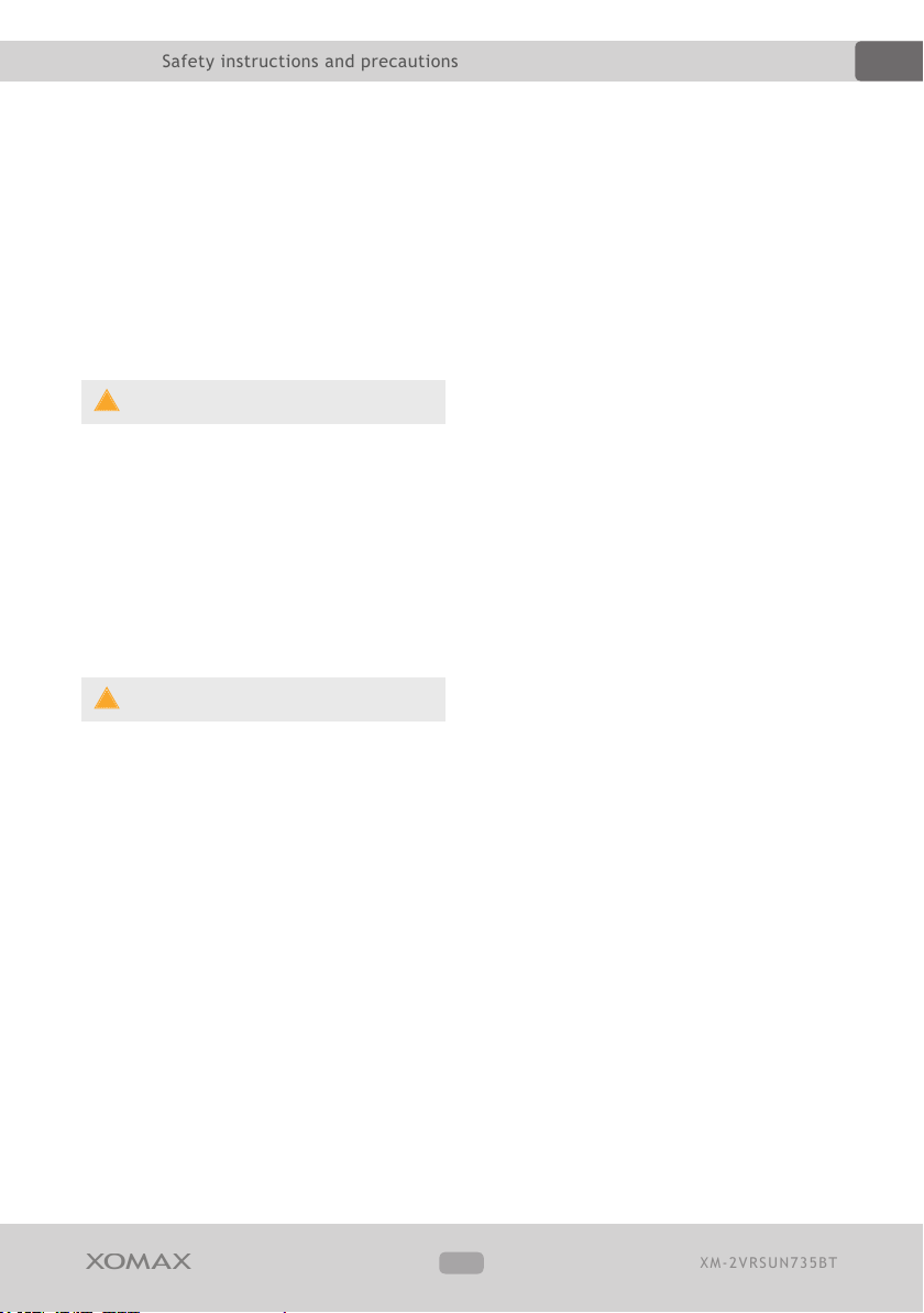
Safety instructions and
precautions
Handling by stop only
To avoid any accidents please don't
handle the unit while you driving.
Please stop and park the vehicle
at safety place and handle the unit
casually.
Installation
Please read the following manual
carefully before you install the
unit. We recommend you to let the
technician install the unit in your
vehicle.
Regular loudness
Please set the loudness of the unit
to the appropriate level so you were
still able to hear exterior noises
especially traf c warning signals.
Furthermore the higher loudness
level can damage your hearing
organs.
tions to professional technicians.
Due to awed warranty seal the
warranty becomes invalid.
Power supply
Use the unit connected only to 12 Volt
on-board power supply. The minus (-)
should be connected with the ground
(GND) (negative).
Due to the wrong grounding exists the
danger of re. In case of doubt please
consult with professional technicians.
Replacement of fuses
While replacing the fuse please make
sure that the new fuse has the same
properties as the old one, especially the
amperage.
Overheating
Do not occlude the vent holes to avoid
the heat generation and accumulation
in the unit. Otherwise exists the danger
of re.
Repair of the unit
Do not open the unit. Do not try to
repair the unit by yourself due to
any emerging technical problems.
While opening the unit by yourself
exists the danger to be electrocuted.
Do not use the unit any further since
you detect any kind of technical
problems. Leave all the repair opera-
Regular temperature
Please make sure that the temperature
inside the vehicle amounts to not more
than +60 C. If it's too hot inside the
vehicle, do not turn the unit on until
the inside temperature of the cabin
descends.
Cleaning of the unit
5
Page 6
XM-2VRSUN735BT
XOMAX
Thema:
Safety instructions and precautions
!
!
Please keep the unit clean and remove
the dust from it regularly. Please use for
that a soft and dry cleaning rag.
Major soilings can be removed carefully
with the wet cleaning rag. Do not use
any chemical or alcohol-containing
detergents to avoid the damage of the
unit's varnish.
Handling the touchscreen
Do not press the touch keys or other
symbols too hard – it may lead to image
distor tions, unit malfunctions and
touchscreen damages.
Do not use any sharp articles to use
the touchscreen. Please handle the
touchscreen with your nger or with the
appropriate stylus.
DE
Moisture
To avoid the danger of re or the
electric shock do not put the unit in to
the moist environment (e.g. adverse
weather conditions, inappropriate wet
cleaning etc.)
6
Page 7
XM-2VRSUN735BT
XOMAX
Thema:
Safety instructions and precautions
DE
Specifications
Allgemeine Daten
Operating voltage ........................... 12V DC
Fuse ................................................... 15 A
Button illumination colour ...................... blue
Installation size .............. 2DIN (Doppel DIN)
Audio
Output power ........................... 4 x 60 Watt
Loudspeaker impedance ..................... 4 Ohm
TFT LCD Bildschirm
Diagonal ........................ 6,2 Zoll (ca.16 cm)
Image ratio ....................... 16:9 Widescreen
Resolution ........................... 800 x 480 Pixel
Typ .................. TFT LCD Touchscreen Display
FM-Radio Receiver
Frequency range .................. 87.5 - 108 MHz
AM-Radio Receiver
Frequency range .................. 522 - 1620 KHz
US B -por t 1 (fron t)
Plug type ........................................... Typ A
Max. supported volume ..................... 128 GB
Filesystem ............................... exFAT, FAT32
Bluetooth
Version ..................................... 2.0 Class 2
Prole ............................... hands free, A2DP
Frequency ........................ 2.4GHz Spektrum
Navigation
Maps .............................................. Europa
Any alternations and changes of
technical data or/and design due
to technical update of some mo-
dels need no advertisement. Errors
expected.
USB-port 2 (rear)
Plug type ........................................... Typ A
Max. supported volume ..................... 128 GB
Filesystem ............................... exFAT, FAT32
SD-card slot
Plug type ..... MicroSD, MicroSDHC, MicroSDXC
Max. supported volume ..................... 128 GB
Filesystem ............................... exFAT, FAT32
7
Page 8
XM-2VRSUN735BT
XOMAX
Thema:
Safety instructions and precautions
i
DE
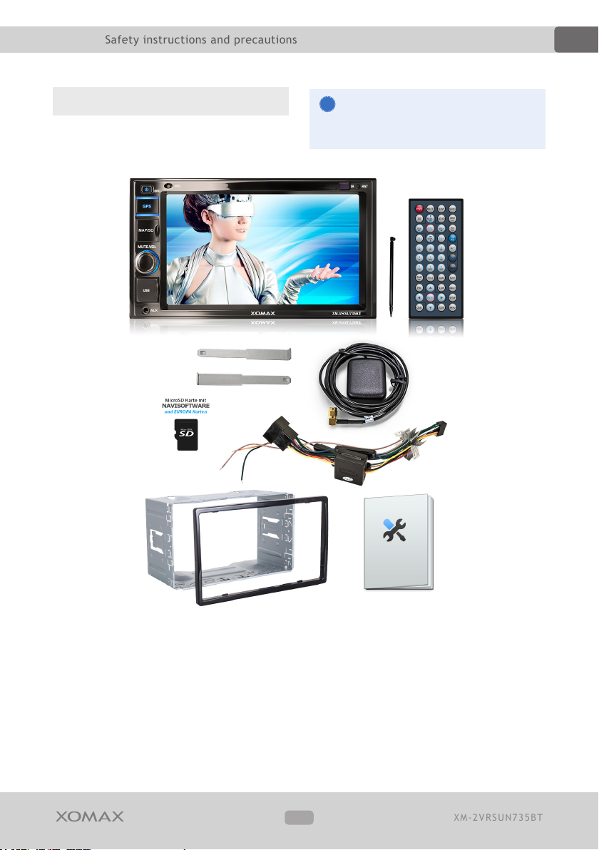
Package content
Please check the accessories on
completeness:
A
C
D
Please note: the package content
may vary due to technical updates.
B
E
F
G H
radio
A
remote control and Stylus
B
Mounting material
C
Navigation software on the micro SD
D
memory card
The images serve as example. Optically the may vary from the original.
GPS-aerial
E
ISO cable
F
2DIN cage and trims
G
installation manual
H
8
Page 9
XM-2VRSUN735BT
XOMAX
Thema:
Safety instructions and precautions
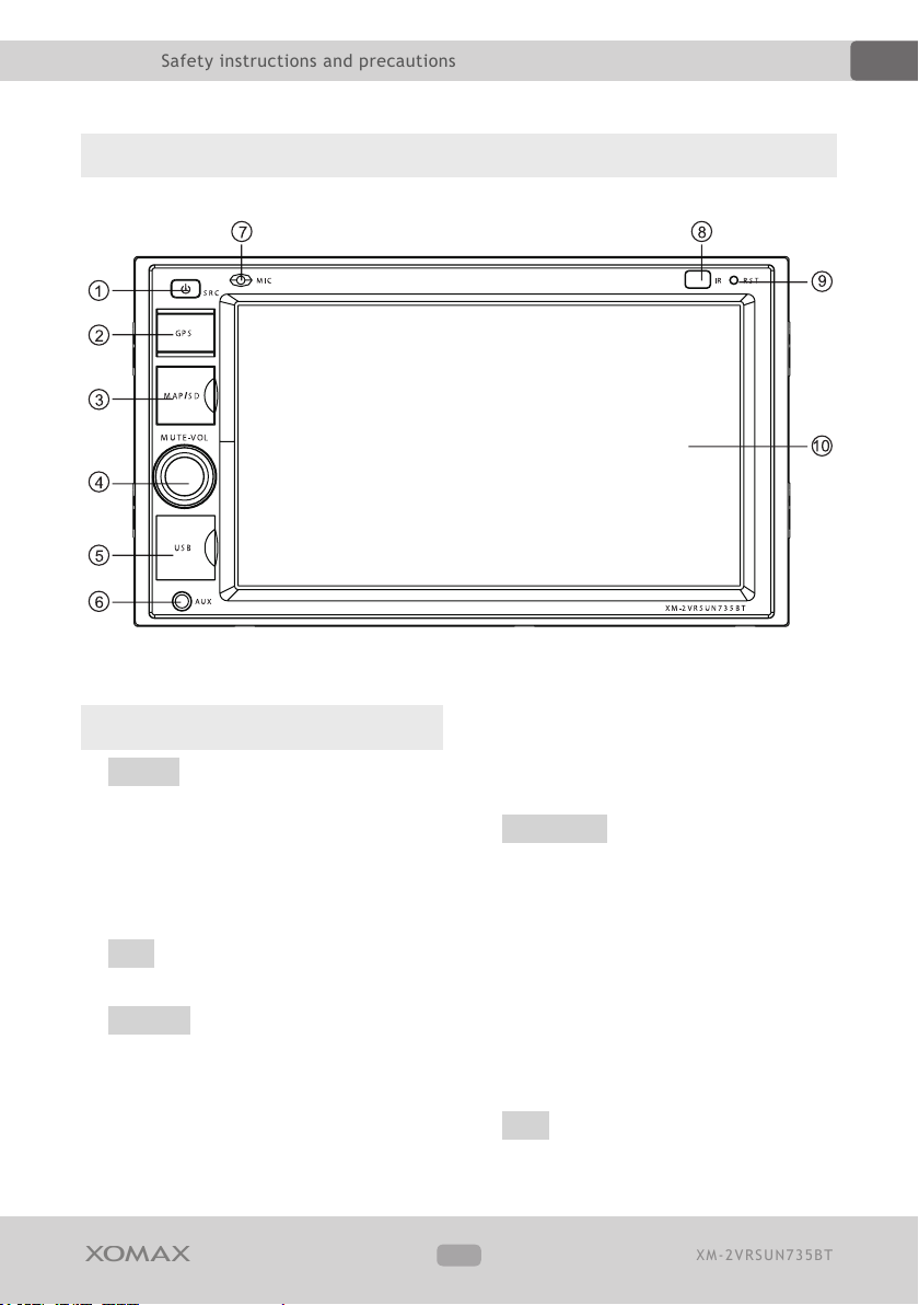
Operating elements of the unit
DE
Operating elements
?/SRC Power/main menu
1
Press this button will turn on power,
during working longer press this button
will turn offpower.
On any mode, shortly press will return
main menu.
GPS navigation mode
2
Switches to navigation mode.
MAP/SD microS D card slots
3
Insert map card to read navigation map
data.
The indicated with "SD" card slot is
reserved for the user's own micro SD-/
SDHC- memor y cards (in exFat or Fat32
le system, 128GB max.) with the
customer's per sonal multimedia content
such as music, pictures, videos.
MUTE/VOL Mut e/vol ume
4
Press this button to turn off volume
output, press it again to restore the
previous volume level.
Press this button to turn off volume
output, press it again to restore the
previous volume level.
Long press MUTE button to turn of f TF T
screen, and short press it so that TFT
screen shall be re-lit.
USB USB slot
5
Insert USB removable device so as to
9
Page 10
XM-2VRSUN735BT
XOMAX
Thema:
Safety instructions and precautions
read audio/video files.
Warning: You can only use either front
or rear USB at a time. Never connect
both front and rear USB at the same
time! This could cause malfunctions.
AUX AUX
6
To input external audio.
Warning: You can only use either front
or rear AUX at a time. Never connect
both front and rear AUX at the same
time.
MIC bluetooth microphone
7
Is used during hand-free phone calling
via Bluetooth. The microphone should not
be blocked to achieve the best possible
sound quality.
IR Infrared
8
To receive infrared signal from the
remote control.
DE
RST reset
9
Deletes all the customer's adjustments
and sets the unit back to factory
settings.
Diplay
A
10
Page 11
XM-2VRSUN735BT
XOMAX
Thema:
Safety instructions and precautions
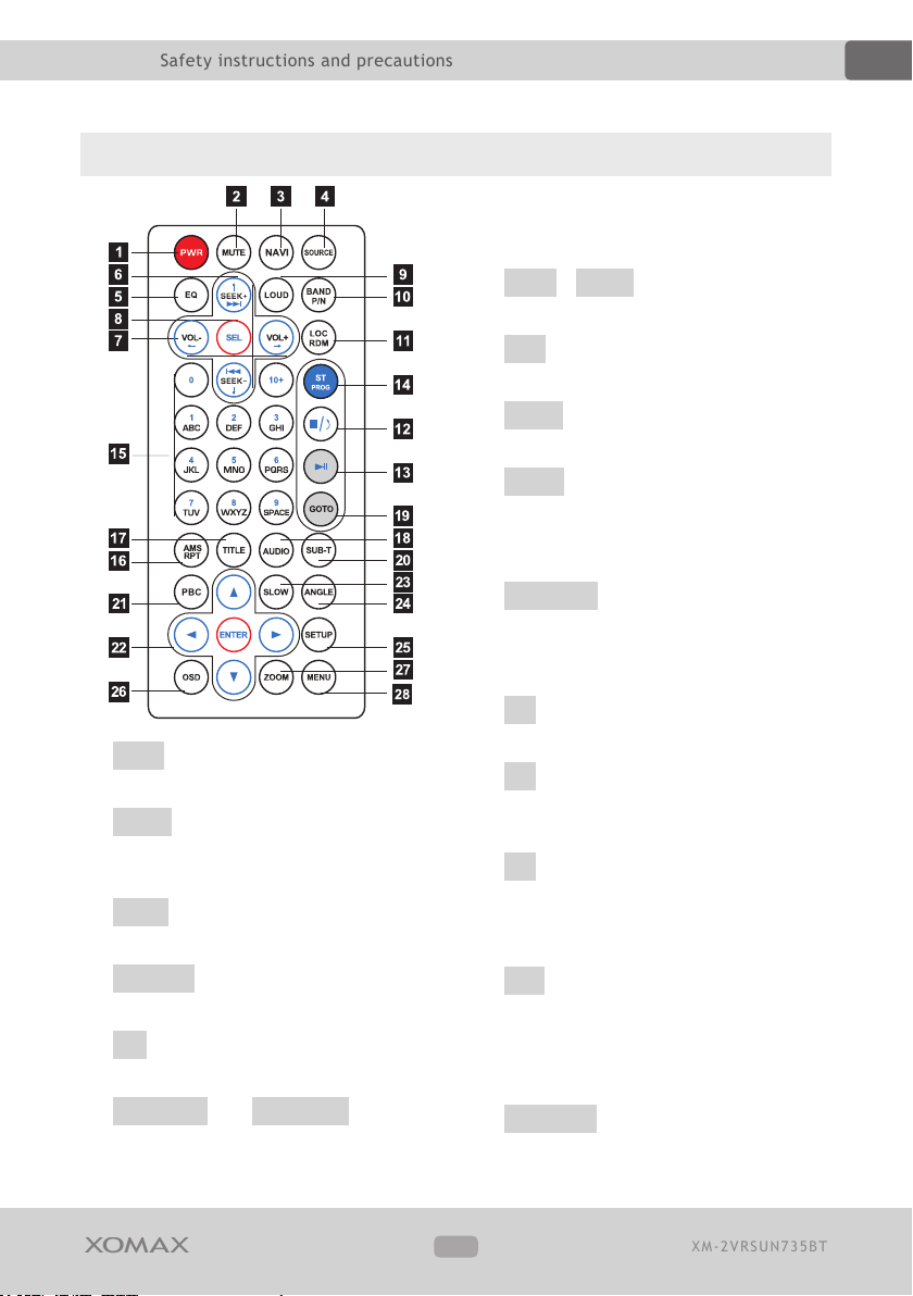
Remote control
DE
In normal playback MP3, USB, SD
songs, press this button to previous
song or next song.
7. VOL- / VO L+ Press this button to
increase or decrease volume level.
8. SEL Press this button to choose
sound feature.
9. LOUD Press this button to star tup
LOUD function.
10. BAND In radio mode, press this
button to choose band.In VCD, DVD
mode, press this button to choose
AUTO, PAL or NTSC system.
11. LOC/RDM In radio mode, press this
button to switch between local and
direction, In VCD, CD mode, press
this key to randomly play.
1. PWR Press once to switch on, press
again to switch off.
2. MUTE Press once to turn off audio
output, press again to resume
volume level.
3. NAVI Press it to enter to exit the
navigation.
4. SOURCE Press this button to
choose audio sources.
5. EQ Press this button to choose
POP, ROCK, CLASSIC, EQ off.
6. SEEK-/8 and SEEK+/7
12. • Press this button to stop
playing.
13. < Press this button to switch
between play and pause, In stop
mode, press this button to play.
14. ST In radio mode, press this button
to choose stereo or mono station. In
audio mode, it can help stop button
to programmed play.
15. 0-9 Press this button to choose
desired song, section, preset
stations. Decimal numbers, for
example the 19th song, press 10+
and 9 button.
16. AMS/RP T In radio mode, press this
button to browse stored stations.
11
Page 12

XM-2VRSUN735BT
XOMAX
Thema:
Safety instructions and precautions
DE
In audio mode, press this button to
play repeatedly.
17. TITLE In DVD mode, press this
button to play back to the top menu
of disc. (not suppor ted)
18. AUDIO In DVD mode, press this
button to switch language of
dialogue. In VCD mode, press this
button to choose left track, right
track,and stereo. (not supported)
19. GOTO In DVD mode, press this
button, you can dene playing time.
20. SUB -T In DVD mode, press this
button to switch language of subtitle.
(not supported)
21. PBC In VCD mode, press this
button to display all song menus,
work with number button to choose
songs. (not supported)
22. Š > ‰ ‹ When playing MP3, USB,
SD returns to song menu, up, down
selections can be up ‰ button or
down ‹ key to select up and down,
select and press ENTER key to
conrm. The selected tracks can be
played. Press the left or right arrow
keys to Š or > key, can be on the
next page function operation.
button to choose different set items.
26. OSD Press this button to display
the title chapter and the left time.
27. ZOOM In DVD/VCD mode, press
this button to ZOOM in/out. (not
supported)
28. MENU Press button to back to the
main menu.
23. SLOW In audio mode, press this
button to slow backward and slow
forward.
24. ANGLE In DVD mode, press this
button to change play angle. (not
supported)
25. SETUP In audio mode, press this
12
Page 13

XM-2VRSUN735BT
XOMAX
Thema:
Installation
i
!
!
DE
Installation
Installation notes
Here you can nd relevant installation
notes and common information.
The detailed installation manual
you can nd on our homepage www.
xomax.de.
The printed version of a common
installation manual you can nd in
the package.
We recommend you to let the
technician install the unit in your
vehicle.
Before the installation
WARNING!
Please read the following manual care-
fully before you install the unit.
Damages caused due to an inapprop-
riate installation will not be covered by
warranty.
If you do not want to risk your warranty
entitlement, please let the technician
install the unit in your vehicle.
» To avoid a short circuit please
disconnect the vehicle battery before
the installation. To do it properly please
read the manual of your vehicle.
» Make sure that your vehicle is
equipped with a car radio slot of
required size (2DIN)
» As may be the case you will need
a suitable faceplate, adapter or other
accessories. These could be provided
from your local specialist supplier.
» The connection cables may not be
cutted or short-circuited. Otherwise the
warranty becomes invalid.
» Before the installation please make
sure that your vehicle has the 12 Volt
on-board power supply.
» The minus (-) should be connected
with the ground (GND) (negative).
» Please tag the polarity of the avai-
lable speakers before you disconnect
the vehicle battery.
» A proper grounding of the unit's
housing requires a clean ground
connection. Thus the grounding area
should be rust-, stain- and dust-free.
» Please ground the cable separately
from other heavy current devices such
as an amplier etc.
» Please ensure that the colored cables
are connected according to the wiring
diagram. The wrong wiring may lead to
malfunctions or even damages of the
electric elements of the vehicle.
» Please note that the connection
cables of this unit and of the other
devices may have the same purpose
but the different color. For this reason
while connecting this unit with the
13
Page 14

XM-2VRSUN735BT
XOMAX
Thema:
Installation
DE
other devices please ensure that both
of the cables in each case have the
same purpose. To connect everything
correctly please refer to the manuals of
the both devices.
» Please ensure that the negative
speaker cable is in each case connected
with the negative speaker terminal of
the ISO por t. Do not ever connect the
negative speaker cables with the vehicle
body.
» This unit is designed and construed
for connection with 4 speakers. Do not
combine this unit with devices that are
designed and construed for connection
with 2 speakers.
» The speakers should feature the
impedance of 4-8 Ohm and a sufcient
wattage.
» Please ensure that the speakers you
are connecting with the unit are intact.
Damaged speakers can impair the unit.
» To avoid a short circuit please isolate
all cable junctions and endings of the
unused cables with the electrical tape.
through the engine bay in order to
connect it with the vehicle battery.
» Do not ever connect speaker cables
among one another. In case you do not
want to connect all the 4 speakers with
the unit please isolate the endings of
unused cables with the electrical tape
to prevent a short circuit.
» Do not ever connect the negative
speaker cables with the vehicle body.
» To ensure a awless performance of
the unit the intergration angle should
amount to +/- 30.
» All the cables should be layed and
xated tidy and properly. The cables
should not contact any movable or hot
objects.
» If your vehicle doesn't have an "ACC"
ignition position, please connect the red
cable with the ignition switch. Otherwise the unit will not turn of f automatically, causing the discharging of the
vehicle battery.
» To avoid a rogue and hazardous
short circuit do not lay the yellow cable
14
Page 15

XM-2VRSUN735BT
XOMAX
Thema:
Connection schedule – ISO plug
Connection schedule – ISO plug
DE
15
Page 16

XM-2VRSUN735BT
XOMAX
Thema:
ISO plug configuration
A
B
!
ISO plug configuration
2 1 2 1
4 3 4 3
6 5 6 5
8 7 8 7
DE
Socket A (power supply)
On the A side you can nd the socket
for power supply.
A1 – spare
A2 – spare
A3 – spare
A4 - +12V battery / steady plus (yello)*
A5 – (+) electric antenna (blue)
A6 – spare
A7 - +12Volt ignition plus (red)*
A8 – (-) minus / ground (black)
* - Some vehicle manufacturers use
their own pin assignment. Especially
the terminals A7 (ignition plus) and A4
(steady plus) are often interchanged.
The incorrect connection in this case
leads to following problem: the unit
can not be turned on if the ignition is
off and all the saved settings are lost
as soon as the unit will be turned off. If
these problems appear the connections
A4 and A7 should be interchanged.
Socket B (loud speakers)
On the B side you can nd the speakers
terminals.
B1 – (+) rear right (violet)
B2 – (-) rear right (violet /black)
B3 – (+) front right (gray)
B4 – (-) front right (gray/black)
B5 – (+) front left (white)
B6 – (-) front left (white/black)
B7 – (+) rear left (green)
B8 – (-) rear lef t (green/black)
The terminals are coloured by pairs, in
each case one (+) and one (-).
Though the design of ISO plug is
standardized, it's pin assigment is not
and may vary. Thus in case of mis-
match of connections due to different
pin assignments a simple plug'n'play
connection may lead to grievous errors.
16
Page 17

XM-2VRSUN735BT
XOMAX
Thema:
ISO cable connections
!
ISO cable connections
DE
1
ISO cable
1. Terminal plug
This plug connects the ISO cable
with the unit.
2. ISO plug
This plug connects the ISO cable
with the vehicle. The ISO cable as
such ser ves as an extension cable
for an eased connection of the unit
to the vehicle provided that the
vehicle has a standardized ISO plug
with the appropriate pin assignment.
2
Please note
» The multicore cable may vary depen-
ding on the current model. Though the
conguration of the loud speakers- and
power supply- cables (steady plus,
ignition plus, ground) is consistent.
» Certain patches could be possibly
found not only on the ISO interface
(socket/plug), but immediately on the
device, e.g. ports for the handbrake,
rearview camera, steering wheel
remote control etc.
» The ISO por t may be already inte-
grated in certain units. In this case
an additional ISO cable becomes
unnecessary.
We recommend you to let a
professional technician install the
unit in your vehicle.
17
Page 18

XM-2VRSUN735BT
XOMAX
Thema:
Connection schedule – Cinch multicore
Connection schedule – Cinch multicore
DE
18
Page 19

XM-2VRSUN735BT
XOMAX
Thema:
ISO cable connections
!
ISO cable connections
DE
We recommend you to let a
professional technician install the
unit in your vehicle.
Terminal plug
This plug connects the ISO cable with
the unit.
ISO plug
This plug connects the ISO cable with
the vehicle. The ISO cable as such
serves as an extension cable for an
eased connection of the unit to the
vehicle provided that the vehicle has a
standardized ISO plug with the appropriate pin assignment.
19
Page 20

XM-2VRSUN735BT
XOMAX
Thema:
Startup operations
!
DE
Startup operations
Usage of the remote control
Before the rst usage please remove
the isolation plate.
Aim the remote control at the IR
receiver on the front operating panel.
The IR receiver should not be blocked.
As soon as the remote control does
not work proper the batter y should be
replaced.
Do not expose the remote control to
direct sunlight or air heater.
Replacement of the battery
Replacement instructions:
1. Remove the battery compartment:
push it to the left r st, then pull it out.
2. Remove the old battery and insert
the new one (CR-2025 Lithium).
3. Insert the battery compartment back
into the remote control till it clicks into
place.
The remote control is operated by
CR-2025 Lithium battery.
As soon as the remote control does
not work proper the batter y should be
replaced.
20
Page 21

XM-2VRSUN735BT
XOMAX
Thema:
Startup operations
i
DE
Unit o n/of f
Press the ?/SRC to turn the unit on/
of f.
Insert a microSD card
Insert a microSD card into the slot with
the label side right and the pin side left.
Make sure that the card is intact and
dirt-free.
Insert a USB flash drive
Insert an USB ash drive proper into a
USB plug.
Do not insert any heavy or big USB
ash drives in order not to hit it
accidently - it could cause damages of
the USB plug or USB ash drive.
Factory settings
Pressing the RS T button you can set
the unit back to the factory settings.
Use a pencil or similar to press the
button. After reset the unit shuts down
automatically.
Sart the navigation
Press the NAV I button on the front
panel. A detailed sof tware description
you will nd on the homepage of the
software producer.
Micro SD cards and USB ash
drives should have following le-
system format: FAT32 or exFat.
Maximal supported capacity is 128GB.
USB port supports ash drives only,
no HUBs, no charging devices, no
external harddics.
21
Page 22

XM-2VRSUN735BT
XOMAX
Thema:
Basic functions
Basic functions
Main interface
DE
Radio mode
22
Page 23

XM-2VRSUN735BT
XOMAX
Thema:
Basic functions
SD- / USB-Mode
DE
23
Page 24

XM-2VRSUN735BT
XOMAX
Thema:
Basic functions
Bluetooth Mode
DE
24
Page 25

XM-2VRSUN735BT
XOMAX
Thema:
Basic functions
DE
Wallpaper
In seing menu/main menu, touch wallpaper
icon can enter wallpaper seing interface.
You can choose the wallpaper you like:
up and down sliding can scan wallpapers,
conrm and touch icon can nish
seing.
25
Page 26

XM-2VRSUN735BT
XOMAX
Thema:
Settings
Settings
DE
26
Page 27

XM-2VRSUN735BT
XOMAX
Thema:
Sound setting
Sound setting
DE
27
Page 28

XM-2VRSUN735BT
XOMAX
Thema:
Steering remote control
Steering remote control
DE
28
Page 29

XM-2VRSUN735BT
XOMAX
Thema:
GPS Navigation
GPS Navigation
DE
29
Page 30

XM-2VRSUN735BT
XOMAX
Thema:
Storage media
!
i
DE
Storage media
Supported media
» USB ash drives, ma x. cap aci t y 128GB,
FAT32 or exFAT le system
» micro SD-/SDHC card, max. capacity
128GB, exFat or FAT32 le system
» Alternative sized SD cards can be
used with the help of an USB adapter.
micro S D card
Supported formats
Video
» X VID coded AVI les
» MPEG4 coded AVI les
» MPEG1/2 coded MPG les
» VOB les
Bilder
» JPEG
» BMP
Please note that some les
can have diverse characteristics
(codings, resolutions). It may lead to
disfunctions during the playback.
Disfunctions due to non-com-
pability can not be regarded as a
product's aw and are not covered by
warranty.
ID3 tag (Title, Interpretor)
The ID3 function allows to display the
name of the currently played interpretor,
title and album. The album cover can be
displayed as well. This function is availa-
ble in mp3 format only. The information
should be stored in the mp3 les.
» RMVB Real Player les
The MP4 format will not be supported.
Do not mistake the MPEG4 Codec for
container format MP4.
Audio
» MP3 les (ID3 tag support)
» WMA les
30
Page 31

XM-2VRSUN735BT
XOMAX
Thema:
Rear view camera (optional)
!
DE
Rear view camera (optional)
Common information
A rear view camera is an optional
accessory. Please inform your self by
your local specialist supplier about
current models and their options and
possibilities.
You can nd compatible cameras on the
homepage: www.carmediashop.de
All the cameras are equipped with video
cinch output.
Rear view cameras are to be installed at
the rear of the vehicle. They serve as a
parking assist element and an auxiliary
extension of the viewing angle while
rever sing.
! Please do not rely on the ca-
mera's picture only while reversing.
A rear view camera serves as an
additional assistance, it can not sub-
stitude your full attention driving.
Connection
The camera port CAM is located on the
rear side of the unit.
The yellow cinch jack is the terminal
for the incoming video signal from the
camera. Plug the video cable of the
camera into it.
The unit's cable as well as the camera
itself has to be connected with the rear
lights of the vehicle 12V) to ensure
the correct functionality of the camera
mode.
Start the rear view camera mode
If the camera was connected properly
the unit switches automatically to the
camera mode as soon as you shift the
reverse gear. As soon as you shift any
other gear the unit switches back to the
previous mode.
31
Page 32

XM-2VRSUN735BT
XOMAX
Thema:
AV-IN Mode
AV-IN Mode
Common information
The AUX input allows you to connect an
external device of your choice and play
the content stored there via AUX mode
on unit's sound system. It could be an
MP4-Player, Smartphone, Cellphone,
Tablet, Video-Player, DVB-T Receiver etc.
The AUX port has 3 regular channel:
Video (yellow), Audio Left (white or
black) and Audio Right (red).
Start the AUX mode
Press the sensor key on the screen.
If the device is a videoplayer it's picture
appears on the unit's screen. Otherwise
only the audio signal will be transmitted.
DE
32
Page 33

XM-2VRSUN735BT
XOMAX
Thema:
Common solutions
Common solutions
The following advices are generally valid and refer to diverse Xomax models with
the similar characteristics. Please note that some articles may refer not to your
model exactly and may contain the describtion of features and functions that your
model does not support.
DE
Describtion of the
problem
The remote control
is without function.
Radio stations are
lost:
As soon as the unit
will be turned off all
the stored stations
and user's settings will
be lost.
Cause and solution
Sol ution 1:
Please ensure that the battery lm is removed. By delivery the
battery is protected by a lm which should be removed before
usage.
Solution 2:
The battery could be empty. Please replace it if required.
Solution 3:
Please make sure that the infrared receiver (labelled with IR)
on the control panel is not blocked.
Note:
You can test the functionality of the remote control as follows:
please hold the IR transmitter towards a camera (e.g. a cell
phone camera) and press any button on the remote control. If
the remote control is operative you can see the infrared signal
on the display of the used camera device.
This problem is caused due to a wrong connection of the ISO
cable.
Please interchange the cables for ignition plus and for steady
plus.
Caution:
If these wires have fuses, the latter should be interchanged as
well.
33
Page 34

XM-2VRSUN735BT
XOMAX
Thema:
Common solutions
DE
Poor radio reception:
The radio tuner nds
no broadcaster or the
reception is poor.
The unit does not
turn on.
For problem-solving regarding the radio reception it is
important to know the type of the antenna of your vehicle.
Here are the possible solutions for each type of the antenna:
Typ e 1 – passive antenna:
We recommend you to substitude the existing antenna by the
larger and therefore more ef cient one.
Shark n or r od antennas (under 5 cm) are denitely insuf-
cient.
Typ e 2 – active antenna:
The vehicle provides no current for the ac tive antenna. In this
case a phantom power is required, which provides the ac tive
antenna with the ex ternal power supply.
Typ e 3 – active antenna with diver sity system:
The unit provides no current for the active antenna and has
no diversity suppor t. For this type of antenna is required the
phantom power with an integrated diversity system.
Note:
A phantom power is not to be confused with an antenna
amplier, which is far less efcient.
This problem is in most cases caused due to a wrong connection of the ISO cable.
Please review the pin assignments of the ISO plug and ISO
socket. Pay attention to the proper connection of the ignitionand steady plus and correct the discrepancy if required.
Note:
Though the design of ISO por t is standardized, it's pin
assigment is not and may vary. Thus in case of mismatch
of connections due to dif ferent pin assignments a simple
plug'n'play connection may lead to grievous errors.
34
Page 35

XM-2VRSUN735BT
XOMAX
Thema:
Disposal / recycling information
Disposal / recycling information
DE
Disposal of an old unit / battery
User information regarding disposal of
electric and electronic devices (private
households)
This symbol on products or in their
manuals implies that electric and
electronic devices at the end of their
service life should be separated from
the domestic waist.
Please hand these products for recycling at municipal collection points free
of charge.
The proper disposal of these products
contributes to environment protection.
To nd the nearest collection point
or recycling yard please consult your
municipal administration.
According to the bat tery decree we
make you aware of your obligation to
dispose of empty batteries at municipal
collection points.
Batteries that contain pollutants
(e.g. Hg = mercury, Pb = lead, Cd =
cadmium) are labelled with the symbol
pictured above.
At our place you can free dispose of the
empty batteries purchased at our store.
XOMAX distribution worldwide
Purchase XOMAX car radio online:
https://www.carmediashop.de
XOMAX in the world wide web
XOMAX manufacturer's information:
http://www.xomax.de
Find us
on Facebook
35
 Loading...