

Page 1

Xerox Document Services Platform Series
DocuTech 65/DocuPrint 65
Installation Planning Guide
701P36055
DocuSP version 2.0.x
January 2001
Page 2

Xerox Corporation
Global Knowledge and Language Services
800 Phillips Road
Bldg. 845-17S
Webster, NY 14580-9791
© 2001 by Xerox Corporation. All rights reserved
Copyright protection claimed includes all forms and matters of copyrighted material
and information now allowed by statutory or judicial law or hereinafter granted
including without limitation, material generated from the software programs that are
displayed on the screen such as styles, templates, icons, screen displays, looks, and
so on.
Printed in the U.S.A., U.K., and France.
XEROX®, XEROX Europe®, and XER OX Canada Lim ited® , The Document
Company®, the stylized X, and all names and identifying numbers used in connection
with Xerox products mentioned in this publication are trademarks of XEROX
CORPORATION. All non-Xerox brands and product names are trademarks or
registered trademarks of their respective companies. Other company trademarks are
also acknowledged.
While the information in this Guide is correct at the time of this publication, Xerox
reserves the right at any time to change the information without notice. Changes are
made periodically to this docum ent . Changes and t echinc al updat es will be added in
subsequent editions.
Page 3

Table of contents
Introduction . . . . . . . . . . . . . . . . . . . . . . . . . . . . . . . . . . . . . . . . . . . . . i
About this guide . . . . . . . . . . . . . . . . . . . . . . . . . . . . . . . . . . . . . . . . . . . . . .i
Contents . . . . . . . . . . . . . . . . . . . . . . . . . . . . . . . . . . . . . . . . . . . . . .i
Requirements . . . . . . . . . . . . . . . . . . . . . . . . . . . . . . . . . . . . . . . . . . . . . . ii
Telephone requirements . . . . . . . . . . . . . . . . . . . . . . . . . . . . . . . . . ii
Service requirements . . . . . . . . . . . . . . . . . . . . . . . . . . . . . . . . . . . ii
Canadian industry requirements . . . . . . . . . . . . . . . . . . . . . . . . . . .iii
Electromagnetic comparability . . . . . . . . . . . . . . . . . . . . . . . . . . . . . . . . .iv
United States . . . . . . . . . . . . . . . . . . . . . . . . . . . . . . . . . . . . . . . . .iv
European Union . . . . . . . . . . . . . . . . . . . . . . . . . . . . . . . . . . . . . . .iv
Safety notes . . . . . . . . . . . . . . . . . . . . . . . . . . . . . . . . . . . . . . . . . . . . v
Symbology . . . . . . . . . . . . . . . . . . . . . . . . . . . . . . . . . . . . . . . . . . . . . . . . . v
European Union declaration of conformity . . . . . . . . . . . . . . . . . . . . . . . .vi
Electricity at Work Regulation - UK . . . . . . . . . . . . . . . . . . . . . . . . . . . . .viii
The Regulation . . . . . . . . . . . . . . . . . . . . . . . . . . . . . . . . . . . . . . .viii
Check your understanding . . . . . . . . . . . . . . . . . . . . . . . . . . . . . . .ix
Your responsibility . . . . . . . . . . . . . . . . . . . . . . . . . . . . . . . . . . . . . x
Additional queries . . . . . . . . . . . . . . . . . . . . . . . . . . . . . . . . . . . . . . x
Electrical safety . . . . . . . . . . . . . . . . . . . . . . . . . . . . . . . . . . . . . . . . . . . . .xi
Printer . . . . . . . . . . . . . . . . . . . . . . . . . . . . . . . . . . . . . . . . . . . . . . .xi
Controller . . . . . . . . . . . . . . . . . . . . . . . . . . . . . . . . . . . . . . . . . . . xii
Printer power on/off indicator . . . . . . . . . . . . . . . . . . . . . . . . . . . . . . . . . xiii
Printer or controller - emergency power off . . . . . . . . . . . . . . . . . . . . . . .xiv
Printer - ozone information . . . . . . . . . . . . . . . . . . . . . . . . . . . . . . . . . . .xiv
Printer - laser safety . . . . . . . . . . . . . . . . . . . . . . . . . . . . . . . . . . . . . . . . xv
Printer - operational safety . . . . . . . . . . . . . . . . . . . . . . . . . . . . . . . . . . . xv
1. Planning for the installlation . . . . . . . . . . . . . . . . . . . . . . . . . . . . . . . 1-1
Installation planning responsibilities . . . . . . . . . . . . . . . . . . . . . . . . . . . 1-1
Xerox responsibilities . . . . . . . . . . . . . . . . . . . . . . . . . . . . . . . . . 1-1
Customer responsibilities . . . . . . . . . . . . . . . . . . . . . . . . . . . . . . 1-2
Installation planning tasks . . . . . . . . . . . . . . . . . . . . . . . . . . . . . . . . . . . 1-4
Before scheduling delivery of the DocuT ech 65/DocuPrint 65 system
1-4
2. Installation. . . . . . . . . . . . . . . . . . . . . . . . . . . . . . . . . . . . . . . . . . . . . .2-1
If you encounter a problem . . . . . . . . . . . . . . . . . . . . . . . . . . . . . . . . . . 2-1
DocuTech 65/DocuPrint 65 1
Page 4

Table of contents Installation Planning Guide
Preparing a location for the DocuTech 65/DocuPrint 65 . . . . . . . . . . . . 2-2
Standard equipment location - space requirements . . . . . . . . . . 2-3
Other locations - space requirements . . . . . . . . . . . . . . . . . . . . . 2-4
Product dimensions . . . . . . . . . . . . . . . . . . . . . . . . . . . . . . . . . . 2-6
Electrical requirements . . . . . . . . . . . . . . . . . . . . . . . . . . . . . . . . 2-7
Telephone line requirments . . . . . . . . . . . . . . . . . . . . . . . . . . . . 2-8
Relocating the DocuTech 65/DocuPrint 65 . . . . . . . . . . . . . . . . . . . . . . 2-8
Procedure . . . . . . . . . . . . . . . . . . . . . . . . . . . . . . . . . . . . . . . . . . 2-8
Space requiremen ts . . . . . . . . . . . . . . . . . . . . . . . . . . . . . . . . . 2-11
3. Product overview . . . . . . . . . . . . . . . . . . . . . . . . . . . . . . . . . . . . . . . .3-1
Hardware components . . . . . . . . . . . . . . . . . . . . . . . . . . . . . . . . . . . . . 3-1
Controller components . . . . . . . . . . . . . . . . . . . . . . . . . . . . . . . . 3-2
Printer components . . . . . . . . . . . . . . . . . . . . . . . . . . . . . . . . . . 3-3
Paper trays (trays 1-4) . . . . . . . . . . . . . . . . . . . . . . . . . . . . . . . . 3-4
Bypass tray (tray 5) . . . . . . . . . . . . . . . . . . . . . . . . . . . . . . . . . . 3-4
Haigh Capacity feeder (tray 6) . . . . . . . . . . . . . . . . . . . . . . . . . . 3-6
Finisher . . . . . . . . . . . . . . . . . . . . . . . . . . . . . . . . . . . . . . . . . . . . 3-7
Peripheral hardware components . . . . . . . . . . . . . . . . . . . . . . . 3-10
Controller software . . . . . . . . . . . . . . . . . . . . . . . . . . . . . . . . . . . . . . . 3-11
Modems . . . . . . . . . . . . . . . . . . . . . . . . . . . . . . . . . . . . . . . . . . . . . . . . 3-11
4. Maintenance and support services. . . . . . . . . . . . . . . . . . . . . . . . . .4-1
Xerox support services . . . . . . . . . . . . . . . . . . . . . . . . . . . . . . . . . . . . . 4-1
Customer support . . . . . . . . . . . . . . . . . . . . . . . . . . . . . . . . . . . . 4-2
Operator training . . . . . . . . . . . . . . . . . . . . . . . . . . . . . . . . . . . . . 4-2
Supplies service . . . . . . . . . . . . . . . . . . . . . . . . . . . . . . . . . . . . . 4-2
Routine maintenance . . . . . . . . . . . . . . . . . . . . . . . . . . . . . . . . . . . . . . 4-4
Meter reading and reporting . . . . . . . . . . . . . . . . . . . . . . . . . . . . . . . . . 4-4
Consumable supplies tables . . . . . . . . . . . . . . . . . . . . . . . . . . . . . . . . . 4-4
Dry ink (toner) and “dry ink low” message . . . . . . . . . . . . . . . . . 4-9
Supplies checklist . . . . . . . . . . . . . . . . . . . . . . . . . . . . . . . . . . . 4-10
2 DocuTech 65/DocuPrint 65
Page 5

About this guide
Introduction
The DocuTech 65/DocuP rint 65 Installation Plannin g Guide contains
information on preparing for the delivery and installation of the Xerox
DocuTech 65/DocuPrint 65 Printer.
This guide is intended for the person responsible for coordinating the
installation of the Xerox DocuTech65/DocuPrint 65 printer and controller at
your site. It lists the tasks you need to complete before installation can begin.
If you are a lead operator, or your job involves some programming and
systems administration tasks, as well as coordinating the install of the
DocuTech 65/DocuPrin t 65 system, use the DocuTech 65/DocuPrint 65
Operator Guide to supplement the information in this manual.
Before using this Guide, become familiar with its contents and conventions.
Contents
This section lists the contents of this guide.
•“Introduction” gives a basic overview of the Installation Planning Guide
and its contents. It also contains information on requirements and
certifications required by USA and Canadian regulations.
•“Safety Notes” explains the various symbols, Cautions, and Warnings
pertaining to the safe use and operation of the DocuT ech 65/DocuPrint 65
systems. It also contains information on requirements and certifications
required by the European Union Declaration of Conformity and The UK
Electricity at Work Regulation.
• Chapter 1 “Planning for the installation” covers th e role s a n d
responsibilities for site selection and installation of the DocuTech 65/
DocuPrint 65.
• Chapter 2 “Installation” provides electrical and space requirements for the
installation of the DocuTech 65/DocuPri nt 65.
• Chapter 3 “Product overview” provides a brief overview of the DocuTech
65/DocuPrint 65 system and components.
• Chapter 4 “Maintenance and supplies” contain s information about the
available support services and necessary supplies to maintain the
DocuTech 65/DocuPrint 65, as well as supplies ordering information.
DocuTech 65/DocuPrint 65 i
Page 6

Introduction Installation Planning Guide
Requirements
Telephone requirements
USA FCC requirements:
1. The FCC has established rules that permit the device to be directly
connected to the telephone network. Standardized jacks are used for
these connections. This equipment should not be used on party lines or
coin line s.
2. If this device is malfunctioning, it may also be causing harm to the
telephone network; this device should be disconnected until repair has
been made. If this is not done, the telephone company may temporarily
disconnect service.
3. The telephone company may make changes in its technical operation s
and procedures; if such changes affect the compatibility or use of this
device, the telephone company is required to give adequate notice of the
changes. Yo u will be advised of your right to file a complaint with the FCC.
4. If the telephone company requests information on what equipment is
connected to their lines, inform them of:
a. The telephone number this unit is connected to
b. The ringer equivalence number
c. The USCO jack required
d. The FCC Registration number
Items “b” and “d” are indicated on the label.
The Ringer Equivalence Number (REN) is used to determine how may
devices can be connected to your telephone line. In most areas, the sum
of the RENs of all devices on any one line should not exceed five (5.0). If
too many devices are attached, they may not ring correctly.
Service requirement s
In the event of equipment malfunction, all repairs should be performed by
Xerox or authorized agent. It is the responsibility of users requiring service to
report the need for service to Xerox or to an authorized agent. Service can be
obtained at:
Xerox Customer Support
1301 Ridgeview Drive, Bldg. 301
Lewisville, TX 75067
Telephone: (800) 821-2797
ii DocuTech 65/DocuPrint 65
Page 7

Installation Planning Guide Introduction
Canadian industry requirements
Notice: The Canadian Industry Canada label identifies certified equipment.
This certification means that the equipment meets certain
telecommunications network protective, operational and safety requirements.
The Department does not guarantee the equipment will operate to the user’s
satisfaction.
1. Before installing this equipment, users should ensure that it is permissible
to be connected to the facilities of the local telecommunications company.
The equipment must also be installed using an acceptable method of
connection. In some cases, the company’s inside wiring associated with a
single line individual service may be extended by means of a certified
connector assembly (telephone extension cord). The customer should be
aware that compliance with the above conditions may not prevent
degradation of service in some situations.
2. Repairs to certified equipment should be made by an authorized
Canadian maintenance facility designated by the supplier. Any repairs or
alterations made by the user to this equipment, or equipment
malfunctions, may give the telecommunication s company cause to
request the user to disconnect the equipment.
3. Users should ensure for their own protection that the electrical ground
connections of the power utility, telephone lines and internal met allic
water pipe system, if present, are connected together. This precaution
may be particularly important in rural areas.
CAUTION
Users should not attempt to make such connections themselves, but should
contact the electric inspection authority, or electrician, as appropriate.
4. The Load Number (LN) assigned to each terminal device denotes the
percentage of the total load to be connected to a telephone loop that is
used by the device, to prevent overloading. The termination on a loop
may consist of any combination of devices subject only to the requirement
that the total of the Load Numbers of all the devices does not exceed 100.
For service in Canada call (800) 939-3769
DocuTech 65/DocuPrint 65 iii
Page 8

Introduction Installation Planning Guide
Electrom a gn et ic co mp ara bility
United States
This equipment has been tested and found to comply with the limits for a
Class A digital device, pursuant to part 15 of the FCC Rules. These limits are
designed to provide reasonable protection against harmful interference when
the equipment is operated in a commercial environment. This equipment
generates, uses, and can radiate radio frequency energy and, if not installed
and used in accordance with the instruction manual, may cause harmful
interference to radio communications. Operation of this equipment in a
residential area is likely to cause harmful interference, in which case the user
will be required to correct the interference at his own expense.
Changes or modifications to this equipment not specifically approved by the
Xerox Corporation may void the user’s authority to operate this equipment.
Shielded cables must be used with this equipment to maintain compliance
with FCC regulations.
This Class “A” digital apparatus complies with Canadian ICES-003.
Cet appareil numérique de la classe “A” est conforme à la norme NMB-003 du
Canada.
European Union
This is a Class A product. In a domestic environment, this product may
cause radio interference, in which case the user may be required to take
adequate measures.
Changes or modifications to this equipment not specifically approved by
Xerox Europe may void the user’s authority to operate this equipment.
Shielded cables must be used with this equipment to maintain compliance
with the EMC Directive (89/336/EEC).
In order to allow this equipment to operate in proximity to Industrial,
Scientific, and Medical (ISM) equipment, the external radiation from ISM
equipment may have to be limited or special mitigation measures taken.
WARNING
WARNING
iv DocuTech 65/DocuPrint 65
Page 9

Symbology
Safety notes
Please read the following instructions carefully before planning your install
and/or operating the DocuTech 65/DocuP rint 65. Refer to them as needed to
ensure the safe installation and operation of your equipment.
The safety testing and performance of this product have been verified
using Xerox materials only
Your Xerox DocuTech 65/DocuPrint 65 and its supplies have been designed
and tested to meet strict safety requirements. These include safety agency
examination and approval, and compliance to established environm ent al
standards.
Follow all warnings and instructions marked on or supplied with the product.
Various symbols are used on the printer and in the documentation.
The symbol on the printer that indicates a hot surface is shown in Figure 1.
Figure 1. Hot surface symbol
Another symbol that indicates a heated surface is shown in Figure 2.
Figure 2. Heated surface symbol
DocuTech 65/DocuPrint 65 v
Page 10

Safety notes Installation Planning Guide
WARNING
Warnings indicate possible serious personal injury if you do not strictly
follow the practice, procedure, condition, or statement that follows the
WARNING.
CAUTION
Cautions indicate that possible system damage or data loss will occur if you
do not carefully follow the practice, procedure, condition or statement that
follows the CAUTION.
European Union declaration of conformity
Approvals and
certification
The CE marking applied to this product symbolizes Xerox Europe Declaration
of Conformity with the following applicable Directives of the European Union
as of the dates indicated below.
January 1, 1995: Council Directive 73/23/EEC amended by Council Directive
93/68/EEC, approximation of the laws of the member states related to low
voltage equipment.
January 1, 1996: Council Directive 89/336/EEC, approximation of the laws of
the member states related to electromagnetic compatibility.
A full declaration, defining the relevant directives and referenced standards
can be obtained from your Xerox Europe representative or by contacting:
Xerox Europe Product Safety,
Xerox Europe Technical Centre,
PO Box 17,
Bessemer Road,
Welwyn Garden City,
Herts AL7 1HE, England
vi DocuTech 65/DocuPrint 65
Page 11

Installation Planning Guide Safety notes
WARNING
This is a Class A product. In a domestic environment this product may
cause radio interference in which case the user may be required to take
adequate measures.
WARNING
This system is certified manufactured and tested in compliance with
strict safety and radio frequency interference regulations. Any
unauthorized alteration which includes the addition of new functions or
the connection of external devices may impact this certification. Please
contact your local Xerox Europe representative for a list of approved
accessories.
Shielded cables must be used with this equipment to maintain
complacence with the EMC Directive (89/336/EEC).
This equipment is not primarily intended for use in a domestic
environment.
WARNING
In order to allow this equipment to operate in proximity to industrial,
scientific and medical (ISM) equipment, the external radiation from the
ISM equipment may have to be limited or special mitigation measures
taken.
DocuTech 65/DocuPrint 65 vii
Page 12

Safety notes Installation Planning Guide
Electricity at Work Regulation - UK
The Electricity at Work Regulation applies only to England and Wales.
The Regulation
The Electricity at Work Regulation 1989 came into force in England and
Wales on the 1 April 1990. This 1989 Regulation places a duty on all
employers and self-employed persons to ensure the electrical systems in their
premises are constructed, maintained and operated in such a manner as to
prevent, so far as reasonably practical, danger. This includes ensuring all
electrical equipment connected to such electrical systems are safely
constructed, maintained and operated.
All Xerox equipment have been designed to exacting safety standards. They
have all undergone a variety of stringent safety tests including earth bond,
insulation resistance and electrical strength tests. Xerox Europe
manufacturing plants have been awarded ISO 9000 quality certification and
are subject to regular audits by the British Standards Institution or equivalent
national standards body.
Xerox equipment which has been properly and regularly serviced and
maintained should not have to undergo additional specific safety tests
pursuant to the 1989 Regulation. Customers wishing to complete safety
testing should contact Xerox Europe T echnical Centre for advice prior to any
test implementation. The address of the Xerox T echnical Centre is provided in
the previous section, European Union declaration of conformity.
Xerox equipment should, however, be properly and regularly serviced and
maintained at all times.
viii DocuTech 65/DocuPrint 65
Page 13

Installation Planning Guide Safety notes
Check your understanding
Please review the questions and answers that follow to ensure that you
understand the Electricity at Work Regulation in England and Wales.
Question What is the Electricity at Work Regulation?
Answer The Electricity at Work Regulation 1989 came into force in England and
Wales on the 1 April 1990. This 1989 Regulation places a duty on all
employers and self-employed person s to ensure the electrical systems in
their premises are constructed, maintained and operated in such a manner as
to prevent, so far as reasonably practicable, danger. This i ncludes ensuring all
electrical products connected to such electrical systems are safely
constructed, maintained and operated.
Question Does Xerox Europe comply with the Electricity at Work Regulation?
Answer The regulation places a duty on all employers and self-employed persons
to ensure the electrical systems in their premises are, effectively safe.
This regulation does not impose on, amongst others, manufa cturers or
suppliers of such electrical systems. However, rest assured that all Xerox
equipment which Xerox Europe and its authorized distributors supply to
customers, conform with all the relevant safety legislation and standards.
Question Is Xerox equipment safe?
Answer All Xerox equipm ent supplied by Xerox Eu rope and their authorized
distributors conform to all relevant safety legislation and standards.
Question Is the Xerox equipment in my premises safe?
Answer All Xerox equipm ent supplied by Xerox Eu rope and their authorized
distributors conform to all relevant safety legislation and standards. However,
like all electrical equipment, they have to be regularly serviced and
maintained by competent persons.
Xerox Europe Customer Service Engineers ensure Xerox equipment is
serviced and maintained to exacting Xerox safety standards. If you would like
your Xerox equipment to be serviced and maintained to such high standards,
please contact your local Xerox Europe Customer Service Organization. They
will be pleased to assist you.
DocuTech 65/DocuPrint 65 ix
Page 14

Safety notes Installation Planning Guide
Question Does the Xerox equipment in my premises comply with the Electricity at
Work Regula tion s ?
Answer All employers and self-employed persons must ensure that the electrical
systems in their premises are safe. This will include ensuring Xerox
equipment in such premises is safe.
Xerox Europe ’s Product Safety function has prepared a guide which contains
a list of tests which may be completed by your Xerox Europe Customer
Service Organization. T HES E TESTS MUST BE CARRIED OUT ONLY BY
PERSONS WHO POSSESS THE RELEVANT SKILL, KNOWLEDGE AND
EXPERIENCE TO CARRY OUT SUCH TESTS.
Please contact the Xerox Europe Customer Service Organization for further
information.
THE USE OF INAPPROPRIATE TEST PROCEDURES AND TEST
EQUIPMENT MAY PROVIDE MISLEADING RESULTS AND MAY CAUSE
DEA T H, PERSONAL INJURY AND/OR DAMAGE TO PROPERTY.
Question I would like to carry out my own safety tests on the Xerox temperament
in my premises.
Answer You may, of course, request such tests as you deem necessary to satisfy
yourself that your Xerox equipment is safe. Your Xerox Europe Customer
Support will be pleased to advise you on such testing.
Question I require records of all tests.
Answer After safety testing, your Xerox Europe Customer Service Engineer will
provide you with a certificate which details the results of all tests completed.
In the event of any defect being noted, the Xerox equipmen t will be swit ch ed
off and disconnected from the supply until the defect has been corrected. You
will be advised of such action to enable such defects to be corrected.
Your responsibility
YOU MUST ENSURE THAT YOUR XEROX EQUIPMENT IS SAFE AT ALL
TIMES.
Additional queries
Please contact the Xerox Europe Technica l Centre if you have any queries
regarding the information provided in this document. The address of the
Xerox Europe T echnical Centre is provided in the previous section, European
Union declaration of conformity .
x DocuTech 65/DocuPrint 65
Page 15

Installation Planning Guide Safety notes
Electrical safety
Attention to the following requirements ensures the safe operation of your
equipment.
Printer
USA/Canada The printer requires a 115V AC outlet, dedicated 20 Amp, 3-wire circuit.
Europe The printer requires a 220-240V outlet, dedicated 13 Amp or 10 Amp circuit.
The equipment must be connected to a grounded mains outlet.
CAUTION
Ensure that the power connection for your printer satisfies these
requirements.
• The power receptacle for the printer must meet the requirements stated
on the data plate on the rear of the printer.
• The socket outlet shall be installed near the equipment within reach of the
10 ft. (3 m) cable and shall be easily accessible.
• Use the power cable that is supplied with your printer and controller. Do
not use an extension cord, or remove or modify the power cord plug.
• Plug the power cable directly into a correctly grounded electrical outlet. If
you are not sure whether or not an outlet is correctly grounded, consult a
qualified electrician.
• Do not use an adapter to connect the printer to an electrical outlet that
lacks a ground connection terminal.
• The power cord is the disconnect device for this printer.
• Do not override or disable electrical or mechanical interlocks.
• Do not push objects into slots or openings on the printer. Electrical shock
or fire may result.
• Do not obstruct ventilation openings. These openings prevent
overheating of the printer.
DocuTech 65/DocuPrint 65 xi
Page 16

Safety notes Installation Planning Guide
Controller
USA/Canada The controller requires a dedicated 115V AC 20 Amp grounded receptacle.
Europe The controller requires a 220-240V, 13 or 10 Amp grounded rec eptacle.
CAUTION
Follow all safety cautions, warnings, and instructions marked on the
controller.
• Ensure that the voltages and frequency rating of the power receptacle
match the electrical rating label on the equipment.
• Do not make electrical or mechanical modifications to the equipment.
• Use the power cable that is supplied with your controller. Do not use an
extension cord, or remove or modify the power cord plug. If the plug must
be changed, a qualified electrician must install the plug correctly on the
power cord.
• Plug the power cable directly into a correctly grounded electrical outlet or
into the power strip that is connected to this outlet. If you are not sure
whether or not the outlet is correctly grounded, consult a qualified
electrician.
• Do not use an adapter to connect the controller to an electrical outlet that
lacks a ground connection terminal.
• The power switch functions as a standby type of device only . The power
cord serves as the primary disconnect device for the system.
• Do not push objects into slots or openings on the equipment. Electrical
shock or fire may result.
• Do not obstruct ventilation openings. These openings prevent
overheating of the controller.
xii DocuTech 65/DocuPrint 65
Page 17
Installation Planning Guide Safety notes
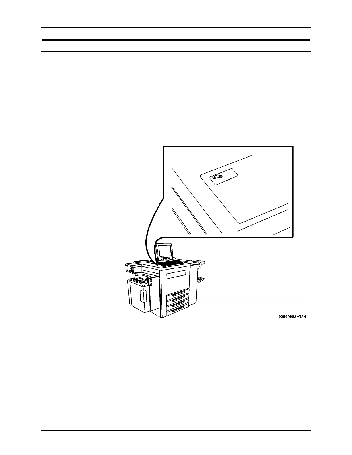
Printer power on/off indicator
A power-on/power-off indicator shows the state of the power for the printer.
This indicator is located on the top front of the printer and has a rectangular
shape. This indicator glows green when printer power is on and emits no light,
is colorless, when the printer power is off.
When you need to determine whether the printer power is on or off, view the
power-on/power-off indicator rather than the message pane on the DocuSP
Print Services main window. Under some conditions, the main window may
not accurately indicate the state of the printer.
The printer power on/off indicator is shown in Figure 3.
Figure 3. Power on/off indic at o r
DocuTech 65/DocuPrint 65 xiii
Page 18

Safety notes Installation Planning Guide
Printer or controller - emergency power of f
If any of the following conditions occur, turn off the equipment immediately
and disconnect the power cable from the electrical outlet. Contact an
authorized Xerox Service Representative to correct the problem:
• The equipment emits unusual odors, or makes unusual noises.
• The power cable is damaged or frayed.
• A wall panel circuit breaker , fuse, or other safety device has been tripped.
• Liquid is spilled into the equipment.
• The equipment is exposed to water damage or flood.
• Any part of the equipment is physically damaged.
NOTE: The only method to remove all power from the printer is to disconnect
the power cable from the electrical outlet.
Printer - ozone information
This product produces ozone during normal operation. The ozone produced is
dependent on print volume and is heavier than air. Install the system in a well
ventilated room with the minimum cubic requirements size listed below.
Providing the correct environmental parameter will ensure that the
concentration levels meet safe limits.
The minimum cubic volume requirement is: 1,765 cubic feet (50 cubic
meters).
To determine if the room has the required volume to meet the ozone
requirement, the length of the room multiplied by its width and height should
be equal to or greater than the cubic volume listed above.
If you need additional information about ozone, please request the Xerox
publication Ozone (part number 600E74140) by calling 1-800-828-6571 in the
United States and Canada. In Xerox Europe countries, call the local welcome
center.
xiv DocuTech 65/DocuPrint 65
Page 19

Installation Planning Guide Safety notes
Printer - laser safety
CAUTION
The use of controls, adjustments or performance of procedures other than
those specified in this guide may result in hazardous light exposure.
With specific regard to lasers, the equipment complies with laser product
performance standards set by governmental, national, and international
agencies as a Class 1 Laser Product. It does not emit hazardous light, as the
beam is totally enclosed during all phases of customer operation and
maintenance.
Printer - operational safety
Safety Quality
Standards
Other National
Standards
Do these To ensure the continued safe operation of your printer, follow these safety
The equipment is manufactured under a BS5750 Quality system accepted by
the British Standards Institution.
The Xerox DocuTech 65/DocuPrint 65 is also certified in compliance with
applicable standards by various national bodies.
guidelines at all times:
• Always connect equipment to a correctly grounded power outlet. If in
doubt, have the outlet checked by a qualified electrician.
• Always follow all warnings and instructions that are marked on or are
supplied with the equipment.
• Always exercise care when moving or relocating the equipment. Please
contact your local Xerox Service Department to arrange relocation of the
printer to a location outside of your building.
• Always locate the printer on a solid support surface (not on plush carpet)
that has adequate strength to support the weight of the printer.
• Always locate the printer in an area that has adequate ventilation and
room for servicing. Refer to the space requirements figures in Chapter 2,
Installation and planning.
• Always use materials and supplies that are specifically designed for your
Xerox equipment. Use of unsuitable materials may result in poor
performance and possibly a hazardous situation.
Do not do these To ensure the continued safe operation of your printer:
• Never use an adapter plug to connect equipment to a power source that
lacks a ground connection terminal.
DocuTech 65/DocuPrint 65 xv
Page 20

Safety notes Installation Planning Guide
• Never obstruct ventilation openings. They are provided to prevent
overheating.
• Never push objects of any kind into the ventilation openings.
• Never attempt any maintenance function that is not specifically described
in the DocuT ech 65/DocuPrint 65 documentation.
• Never remove any covers or guards that are fastened with screws. There
are no operator serviceable areas within these covers.
• Never locate the printer near a radiator or any other heat source.
• Never overr ide or “cheat” any of the electrical or mechanical interlock
devices.
• Never operate the equipment if you notice unusual noises or odors.
Disconnect the power cord from the power outlet and call the Xerox
Welcome Center.
Your Xerox DocuTech 65/DocuPrint 65 printer is certified, manufactured, and
tested in compliance with strict safety and radio frequency interference
regulations. Any unauthorized alteration that includes the addition of new
functions or the connection of external devices may invalidate this
certification. Please contact your local Xerox representative or the Xerox
Welcome Center for a list of approved accessories.
Additional
information - USA
Additional
information -
Europe
Welcome Center phone numbers:
• USA - (800) 821-2797
• Canada - (800) 939-3769
• Europe - local Welcome Center
If you need any additional safety information concerning the equipment or the
Xerox supplied materials, please contact the Xerox Welcome Centre.
If you need any additional safety information concerning the equipment or the
Xerox supplied materials, you may call the following number: 01707 353434
xvi DocuTech 65/DocuPrint 65
Page 21

1. Planning for the installlation
Installation planning responsibilities
This section describes your responsibilities and the responsibilities Xerox has
to you. You will see that some areas overlap and are joint responsibilities.
Xerox responsibilities
Your Xerox representative’s responsibilities prior to, during, and after
installation of the DocuTech 65/DocuPrint 65 printer are:
Site Selection • Assist in site selection .
• Inspect and approve the site.
Installation • Schedule the delivery of the hardware.
• Monitor installation activities.
• Assist you in ordering any supplies required.
• Install the DocuTech 65/DocuPrint 65 printer.
Training • Provide initial operations training.
• Provide information and assistance in registering for Xerox Customer
Education classes.
Service • Review preventive maintenance schedules and service procedures.
• Provide ongoing DocuSP controller and DocuTech 65/DocuPrint 65
maintenance.
• Assist in resolving hardware and software problems.
DocuTech 65/DocuPrint 65 1-1
Page 22

Planning for the installlation Installation Planning Guide
Customer responsibilities
Your responsibilities prior to, during and after installation of the DocuTech 65/
DocuPrint 65 printer are:
Site Personnel Identify a person at your site to be the primary interface with Xerox.
Site Selection and
Preparation
USA/Canada The printer requires a dedicated 115V AC 20 Amp grounded receptacle. The
Europe The printer re quires a 220-240V 13 or 10 Amp grounded re ceptacl e. The
Select and prepare the site for DocuTech 65/DocuPrint 65 printer installation.
The following electrical, telephone, and network services are required:
Electrical requirements
power receptacle for the printer must meet the requirements stated on the
data plate on the rear of the printer.
The contro ller requires a dedicated 115V AC 20 Amp grounded receptacle.
power receptacle for the printer must meet the requirements stated on the
data plate on the rear of the printer
The controller requires a 220-240V 13 or 10 Amp grounded recepta cle.
CAUTION
Do not remove or modify the power cord plug. Do not use a two-prong
adapter to connect the three-prong plug to an ungrounded receptacle.
Personal injury or damage to the printer could occur.
A typical USA 20 Amp receptacle is illustrated in Figure 1-1.
Figure 1-1. USA 20 Amp receptacle
• The power receptacle for the printer must be within easy reach of the
printer’s 10 ft. (3 m) power cord from the right rear corner of the printer,
and the receptacle shall be easily accessible. Do not use an extension
cord.
• If a Phone Share device is used an additional 115V AC 15 or 20 Amp
power receptacle is required within 6 ft. (1.8 m) of the PhoneShare device
location. (For detailed information about using a Phone Share device,
refer to the section, Telephone line requirements.
1-2 DocuTech 65/DocuPrint 65
Page 23

Installation Planning Guide Planning for the installlation
• All configurations require one 115 VAC, 3 wire, 15 Amp receptacle for the
outlet strip that provides receptacles for the controller and its peripheral
devices.
• Use the power strip to connect the telephone line with the controller
external modem. The power st rip has tw o specia l surge -suppressor jacks,
one labeled “In” and the other labeled “Out .” From the wall jack, insert the
phone line into the power strip “In” jack. From the power strip “Out” jack,
insert the phone line into the controller external modem.
Telephone line requirements
NOTE: The telephone line for the Sixth Sense feature must be an analog
telephone line (not a digital telephone line).
• The Sixth Sense connection requires either a dedicated analog telephone
line or a PhoneShare device to share an analog telephone line with up to
three other devices.
• The telephone jack or PhoneShare device must be within the 14 ft. (4.25
m) length of the printer's telephone cord. If a PhoneShare device is used,
it must also be placed within the 25 ft. (7.6 m) length of the telephone cord
from the telephone jack, and within the 6 ft. (1.8 m) length of the power
cord from its assigned power receptacle.
Call the Xerox Welcome Center and provide the telephone number of this
line for entry into the Sixth Sense on-line support system. If a
PhoneShare device is used, also provide the port number on the
PhoneShare device that the printer is using.
• One 10BaseT or 100BaseT Ethernet connection for the controller.
• One telephone line.
Training • Select personnel to train.
• Set up training schedule.
Client
Workstations
Make sure all client workstations that will be submitting print jobs have the
proper hardware, operation system, and networking software required by the
DocuTech 65/DocuPrint 65 printer as client platforms.
Applications Work with your Xerox Systems Analyst to determine requirements for initial
applications.
DocuTech 65/DocuPrint 65 1-3
Page 24

Planning for the installlation Installation Planning Guide
Installation planning tasks
To aid you in installati on plannin g, thi s section provides a list, d escribing tasks
you and your Xerox representative must complete in the days before
scheduling installation. If you have questions about any of these activities,
contact your sales or service representative.
Before scheduling delivery of the DocuTech 65/DocuPrint 65 system
The following activities should be completed before you schedule a delivery
date for the DocuTech 65/DocuPrint 65 Printer:
• Select a location for the DocuTech 65/DocuPrint 65 Printer.
• Prepare the site:
– Install any required electrical service. Order Xerox receptacle kits if
required. Refer to the section, Electrical Requirements if necessary.
– Install any required Ethernet hardware.
– Reserve a network address and hostname for each DocuSP
controller workstation.
• Identify networked client workstations that will submit jobs. Ensure that
the hardware, operation system, and network protocols are supported by
the DocuSP control.
After the preceding activities are complete, schedule a delivery date for the
DocuT ech 65/DocuPrint 65 Printer . This should be done with your Xerox sales
representative.
1-4 DocuTech 65/DocuPrint 65
Page 25

2. Installation
This chapter provides the information you need when you plan the first
installation of the DocuTech 65/DocuPrint 65 by the carrier or Xerox service
representative. It is also needed when you want to relocate the equipment at
some time in the future.
If you encoun ter a problem
In case of problems with the DocuTech 65/DocuPrint 65 installation, consult
the chapter, Problem solving. If you still cannot resolve the problem, please
contact your printer administrator for assistance.
In some cases, the printer administrator may not be available, or the problem
may require more assistance. In those situations, please locate the printer
serial number inside the printer’s front door, to the left of the red button, as
shown in Figure 2-1.
With the serial number ready, contact the Xerox Customer Support Center via
the Welcome Center phone number:
• In USA: 1-800-821-2797
• In Canada: 1-800-939-3769
• In Xerox Europe countries: call the local welcome center
Figure 2-1. Printer serial number
Serial Number
DocuTech 65/DocuPrint 65 2-1
Page 26
Installation Installation Planning Guide
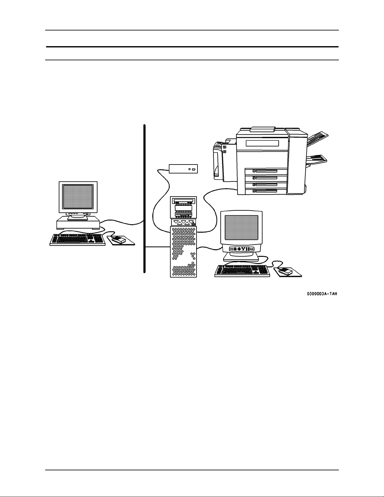
Preparing a location for the DocuTech 65/DocuPrint 65
The printer and controller components are shown in Figure 2-2. The client
workstations and the local network are provided by the customer site.
Figure 2-2. Controller and printer compon ents
Local
Network
Modem
Printer
Client or
DigiPath
Monitor,
Keyboard, and
Mouse
Controller
The controller consists of a CPU, a monitor, a keyboard, a mouse, and an
external modem. The controller may have other accessories such as an
external disk drive and a tape drive for backups.
The printer has an attachable shelf for holding any peripherals. In addition,
the printer has an internal modem.
Only one wall outlet is required to power the controller provided that you use
the power strip. The power strip has eight outlets and a ten-foot cord.
NOTE: Xerox Europe provides its own modems and power strip.
NOTE: In the USA & Canada only, if installing in a hallway or exit route,
allow a minimum of 44 inches (1118 mm) additional clearance in front of the
printer in order to meet the fire code regulations.
Figures 4 through 8 in the following section are presented in the order of
preferred placement. The dimensions assume a movable installation (carpet
no deeper than 0.25 inches or 7 mm). Additional access measurements are
shown in Table 2-2.
2-2 DocuTech 65/DocuPrint 65
Page 27

Installation Planning Guide Installation
The symbols used in the space requirements figures are defined in Figure 2-
3.
Figure 2-3. Symbols used in figures
CPU
Peripherals
Always attempt to place the equipment in the standard location before
selecting any other location.
Table
Printer
Standard equipment location - space requirements
The preferred location of the equipment is called the standard location, shown
in Figure 2-4. The standard location requires:
• CPU on floor, between the printer and the wall
• Monitor, controller modem, keyboard and mouse on top of the printer
CAUTION
There must be a minimum of 5 inches (127 mm) between the controller CPU
and the wall.
Figure 2-4. Standard location space requirements
DocuTech 65/DocuPrint 65 2-3
Page 28

Installation Installation Planning Guide
Other locations - space requirements
If you cannot use the standard location, it is recommended that you place all
of the controller equipment on a table. When you use a table, be sure to place
the CPU on the side of the table that is closest to the printer.
The location of all controller components on a table to the left of the printer is
shown in Figure 2-5.
Figure 2-5. All controller components on a table to the left of the printer
If necessary , you can place all controller components on a table to the right of
the printer as shown in Figure 2-6.
Figure 2-6. All controller components on a table to the right of the
printer
2-4 DocuTech 65/DocuPrint 65
Page 29

Installation Planning Guide Installation
A less desirable alternative is to place the CPU on a table to the right of the
printer as shown in Figure 2-7. Other components would then be placed on
top of the printer.
Figure 2-7. CPU on a table to the right of the printer
Your last choice is to place the CPU on a table to the left of the printer as
shown in Figure 2-8.
Figure 2-8. CPU on a table to the left of the printer
DocuTech 65/DocuPrint 65 2-5
Page 30
Installation Installation Planning Guide
Product dimensions
The dimensions for the table on which the controller components may be
placed are shown in the space requirements figures.
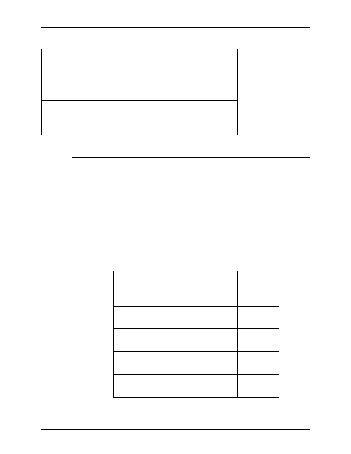
The unpackaged dimensions and weights of the printer and various options
are listed below in Table 2-1. Take these into account when determining the
installation location.
Tab le 2-1. Unpa ckage d dimensions
Product
Printer 353 lb (161
Bypass Tray 8 lb(4 kg) 19.25 x 16.5 x 5 in.(489 x
High Capacity
Feeder with
Integral Bypass
Tray
Finisher 92 lb(43 kg) 26 x 25 x 40 in.(660 x 610 x
Access dimensions to the printer are shown in Table 2-2. The HCF/Bypass is
a combination of the High Capacity Feeder with the Bypass Tray.
Tab le 2-2. Access dim ens ions
Input
Device Output Device
Bypass Tray Finisher 15 in. (381
Left Side
Access to
Printer
mm)
Unpack-
aged Weight
kg)
38 lb(17 kg) 19.5 x 17.75 x 22.5 in.(495
Right Side
Access to
Printer
18 in. (457
mm)
Unpackaged Dimensions
D x W x H
28 x 30 x 40 in.(711 x 762 x
1016 mm)
419 x 127 mm
x 451 x 572 mm)
1016 mm)
Total Access
to Printer Printer
102 in. (2591
mm)
69 in. (1753
mm)
HCF/Bypass Finisher 15 in. (381
mm)
2-6 DocuTech 65/DocuPrint 65
18 in. (457
mm)
102 in. (2591
mm)
69 in. (1753
mm)
Page 31

Installation Planning Guide Installation
Electrical requirements
CAUTION
Do not connect the power cord at this time.
USA/Canada The printer requires a dedicated 115V AC 20 Amp grounded receptacle.
The controller requires a dedicat ed 115V AC 20 Amp grounded receptacle.
Europe The printer re quires a 220-240V 13 or 10 Amp grounded re ceptacl e.
The controller requires a 220-240V 13 or 10 Amp grounded recepta cle.
CAUTION
Do not remove or modify the power cord plug. Do not use a two-prong
adapter to connect the three-prong plug to an ungrounded receptacle.
Personal injury or damage to the printer could occur.
A typical USA 20 Amp receptacle is illustrated in Figure 2-9.
Figure 2-9. USA 20 Amp receptacle
• The power receptacle for the printer must be within easy reach of the
printer’s 10 ft. (3 m) power cord from the right rear corner of the printer,
and the receptacle shall be easily accessible. Do not use an extension
cord.
• If a PhoneShare device is used an additional 115V AC 15 or 20 Amp
power receptacle is required within 6 ft. (1.8 m) of the PhoneShare device
location. For detailed information about using a PhoneShare device, refer
to the section, Telephone line requirements.
• All configurations require one 115 VAC, 3 wire, 15 Amp receptacle for the
outlet strip that provides receptacles for the controller and its peripheral
devices.
• Use the power strip to connect the telephone line with the controller
external modem. The power st rip has tw o specia l surge -suppressor jacks,
one labeled “In” and the other labeled “Out .” From the wall jack, insert the
phone line into the power strip “In” jack. From the power strip “Out” jack,
insert the phone line into the controller external modem.
DocuTech 65/DocuPrint 65 2-7
Page 32

Installation Installation Planning Guide
Telephone line requirments
NOTE: The telephone line for the Sixth Sense feature must be an analog
telephone line (not a digital telephone line).
• The Sixth Sense connection requires either a dedicated analog telephone
line or a PhoneShare device to share an analog telephone line with up to
three other devices.
• The telephone jack or PhoneShare device must be within the 14 ft. (4.25
m) length of the printer's telephone cord. If a PhoneShare device is used,
it must also be placed within the 25 ft. (7.6 m) length of the telephone cord
from the telephone jack, and within the 6 ft. (1.8 m) length of the power
cord from its assigned power receptacle.
Call the Xerox Welcome Center and provide the telephone number of this
line for entry into the Sixth Sense on-line support system. If a
PhoneShare device is used, also provide the port number on the
PhoneShare device that the printer is using.
Relocating the DocuTech 65/DocuPrint 65
Before relocating the DocuTech 65/DocuPrint 65, review the following
information:
• In the previous chapter, Safety notes
• In this chapter, Preparing a location for the DocuTech 65/DocuPrint 65
Relocation to a site on the same floor or to a different floor via an elevator can
be handled without assistance from Xerox. If you need to relocate to a
different building, contact Xerox.
Procedure
Use the following procedure to relocate your printer and controller:
• Power-off the printer and unplug the telephone cord, power cord and any
network connections.
• Power-off the peripherals, the modem, the CPU, and then the monitor
using the correct shutdown procedure.
• Unplug the power strip from the wall.
• Unplug the CPU, the monitor, the modem, and the peripherals from the
power strip.
• Disconnect the CPU from the printer.
• Disconnect the CPU from the monitor, keyboard, and mouse.
• If the monitor, keyboard, and mouse are on the top of the printer, remove
them before moving the printer.
2-8 DocuTech 65/DocuPrint 65
Page 33

Installation Planning Guide Installation
To remove the monitor:
1. Ensure that the monitor is unplugged from the power strip.
2. Face the back of the monitor.
3. Tilt the back of the monitor upwards
4. Locate the two retainers (one on each side of the base of the monitor,
holding the wire brackets in place).
5. Unscrew the two 12 mm screws from each of the two retainers.
6. Remove the retainers.
7. Save all removed hardwa re. (You will need this hardware when you
attempt to reinstall the monitor.)
8. With the monitor back tilted upwards, rotate the rear wire bracket
upward, then lift upward to remove.
9. Face the front of the monitor.
10. Tilt the front of the monitor upward.
1 1. Rotate the front wire bracket upward, then lift to remove.
12. S av e all remove d hardwa r e. (You will need this hardware when you
attempt to reinstall the monitor.)
13. Lift up the monitor and place it on a wheeled-cart for transport to the
new location.
• Unlock the printer front and rear right wheels by pressing the lever
upward on each set of casters, as shown in Figure 2-10. Do not attempt to
unlock the left wheels. After the right wheels are unlocked, to enable
better steering and avoid tipping, move the printer from the left to right.
DocuTech 65/DocuPrint 65 2-9
Page 34

Installation Installation Planning Guide
Figure 2-10. Unlock and lock actions for the casters
Unlock
Lock
• Push the printer from the right side (the side with the swivel casters) so
that you can steer it easily.
• At the new location, ensure that the safety requirements can be met.
• Attempt to place the equipment in the preferred location as shown in this
chapter, in Figure 2-4. If the standard location is not possible, use one of
the other locations.
• Ensure that the space requirements are met.
• Re-establish all power strip, controller, m odem , and printer connections.
To replace the monitor:
1. Place the monitor on the printer.
2. Tilt the front of the monitor upwards.
3. Install the ends of the front wire bracket into the front two holes. (The
wire bracket crosses over the base of the monitor.)
4. Rotate the wire bracket down into place.
5. Tilt the back of the monitor upward.
6. Install the ends of the rear wire bracket into the rear two holes. (The
wire bracket crosses over the base of the monitor.)
2-10 DocuTech 65/DocuPrint 65
Page 35

Installation Planning Guide Installation
7. Rotate the wire bracket down into place.
8. Install the two retainers around the two wire brackets.
9. Secure the retainers using two 12 mm screws per retainer.
• Ensure that you have used the “In” and “Out” surge-suppressor jacks
when you re-established the modem connections.
• Plug the power strip into the wall receptacle.
• Power on the controller using the correct power-on procedure.
• Power on the printer using the correct power-on procedure. Reenter the
printer telephone number if it has changed and inform the Welcome
Center of the new number.
• Lock the printer casters in position by pressing the caster wheel lever
down.
Space requirements
The dimensions shown in Figures 4 through 8 and in Tabl e 2-2 in this chapter
are also required when you relocate the controller and printer.
DocuTech 65/DocuPrint 65 2-11
Page 36

Installation Installation Planning Guide
2-12 DocuTech 65/DocuPrint 65
Page 37

3. Product overview
This chapter will introduce the controller and overview the capabilities of the
printer.
Hardware components
The main DocuTech 65/DocuP rint 65 component s are:
• Controller (CPU with external modem, CD-ROM drive, diskette drive,
• Printer (with internal modem)
Peripheral components may include:
• External SCSI Hard Drive
• External Tape Drive
monitor, keyboard, and mouse)
Peripheral components may be contained within a special accessory shelf
that is attached to the printer.
DocuTech 65/DocuPrint 65 3-1
Page 38

Product overview Installation Planning Guide
Control ler com ponen ts
The main controller components are shown in Figure 3-1.
Figure 3-1. Controller components
CDROM
Drive
Diskette
Drive
Modem
Power
Off On
Power On/Off
3-2 DocuTech 65/DocuPrint 65
Page 39

Installation Planning Guide Product overview
Printer components
The main components of the printer are shown in Figure 3-2.
Figure 3-2. Printer components
Tray 5,
Bypass T ray
for odd size
or special
Top
Tray
stock
Stacker
Finisher
for stapled
sets
Tray 6, High Capacity
Feeder with 3100 sheet
Paper Trays 1-4 hold many
types of stock
capacity for main stock
The following information sources are provided to assist you:
• Power-on/power-off indicator is on the top front of the printer. It glows
green when on and emits no light when off.
• Labels are affixed at the points of need throughout the system. They
depict information about loading the paper stock.
• Green or Gold colored areas act as markers.
– Gold colored areas typically indicate the handle or levers to push or
pull when removing Replaceable Modules or Cartridges.
– Green colored areas are where you clear jams.
DocuTech 65/DocuPrint 65 3-3
Page 40
Product overview Installation Planning Guide
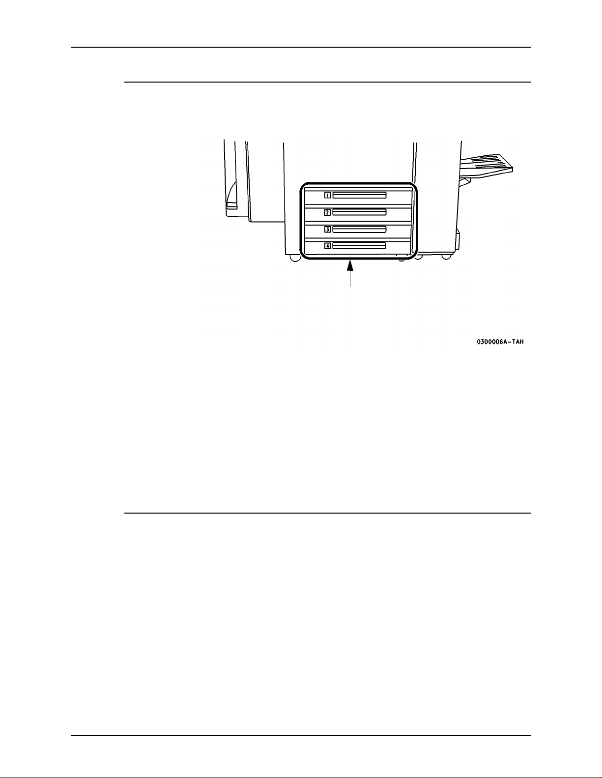
Paper trays (tr ays 1-4)
Paper trays 1-4 are shown below in Figure 3-3.
Figure 3-3. Trays 1-4
Trays 1 - 4
The Paper Trays hold up to 500 sheets of 20 lb (75 gsm) stock each. You can
adjust the trays to hold many sizes fo paper, from 5.5 x 8.5 inches (140 x 216
mm) up to 11 x 17 inches (279 x 432 mm or A3). To handle 12 x 18 inch paper,
a tray must be specially set up. If you wish to dedicate a tray permanently to
handle this size paper please contact the Xerox Welcome Center.
Refer to the chapter on Maintenance and supplies for a listing of acceptable
stock and paper sizes, orientations, and weights.
NOTE: To achieve the maximum copying speed, paper should be loaded
Long Edge Feed in the paper trays whenever possible.
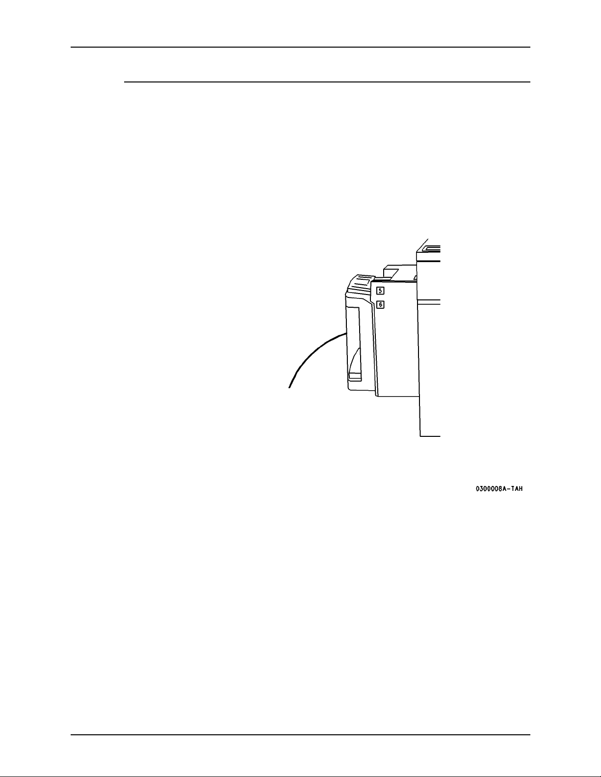
Bypass tray (tray 5)
The Bypass Tray (Tray 5) is an additional paper tray designed for quick and
easy loading of both standard and non-standard paper. It can physically
extend to accommodate different stock sizes and orientations. You can load a
maximum of 50 sheets of standard weight 20 pound (75 gsm) stock. If using a
heavier stock, fill the tray only to the maximum-fill line.
The Bypass Tray has a capability of 4 to 12 inches (102 to 305 mm); 5.83 to
18 inches (148 x 457 mm).
The Bypass Tray can also hold non-standard size and weight paper such as
transparencies, labels, covers, index, and bond paper. The Bypass Tray is
shown below in Figure 3-4.
3-4 DocuTech 65/DocuPrint 65
Page 41

Installation Planning Guide Product overview
Figure 3-4. Bypass Tray
Tray 5
DocuTech 65/DocuPrint 65 3-5
Page 42
Product overview Installation Planning Guide
Haigh Capacity feeder (tray 6)
The High Capacity Feeder (Tray 6) is located under the Bypass Tray and
saves you from having to load the other individual paper trays with 8.5 x 11
inch (216 x 279 mm) paper often. You can load 3100 sheet s of 20 pound (75
gsm) 8.5 x 11 inch (216 x 279 mm) Long Edge Feed (LEF) paper. The High
Capacity Feeder can feed only 8.5 x 1 1 inch (216 x 279 mm) or A4 LEF paper
and cannot be adjusted to hold any other sizes or orientations.
Figure 3-5. High Capacity Feeder
Tray 6
High
Capacity
Feeder
3-6 DocuTech 65/DocuPrint 65
Page 43
Installation Planning Guide Product overview
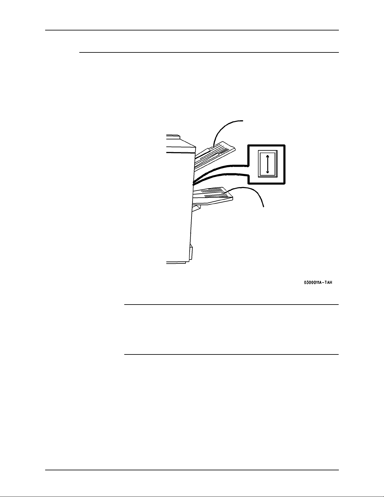
Finisher
The Finisher consists of the Top Tray and the Stacker Tray, as shown below
in Figure 3-6.
Figure 3-6. Fi ni sher components
Top Tray
Finisher
button
Stapler is
within the
finisher
Press the Finisher Button
to unload the Stacker Tray
during a print run
Top Tray
The Top Tray holds sheets that are purged from the system or up to 250 prints
on small paper that cannot be stapled. It cannot be selected as an output
destination.
Stacker Tray
The Stacker Tray is the output tray for all other jobs. The Stacker Tray has two
staplers, each with a 5000-staple cartridge, that can staple sheets ranging in
size from 6.7 x 8 inch (170 x 203 mm) to 12 x 18 inch (305 x 457 mm) of 16 to
1 10 lb (60 to 200 gsm) stock. Up to a maximum of 50 sheets of 20 lb (80 gsm)
can be stapled.
DocuTech 65/DocuPrint 65 3-7
Page 44

Product overview Installation Planning Guide
Stapling
Removing any of the output while the printer is running may produce finished
sets that are incorrectly staple.
To ensure that the stapling of thin sets is satisfactory, the printer performs the
fol lowing actions.
Finishers before
the end of 1998
Finishers after the
end of 1998
After 30 finished sets of 15 sheets, the printer:
1. cycles down
2. may raise a message to empty the Finisher (Stacker Tray)
3. waits briefly , whether the sets are removed or not
4. cycles up and resumes printing.
After 30 finished sets of 15 sheets, the printer:
1. cycles down
2. raises a message to empty the Stacker
3. waits until the sets are removed
4. raises the Stacker Tray
5. cycles up and resumes printing.
If these parameters are not satisfactory for your printing, contact Xerox.
3-8 DocuTech 65/DocuPrint 65
Page 45
Installation Planning Guide Product overview
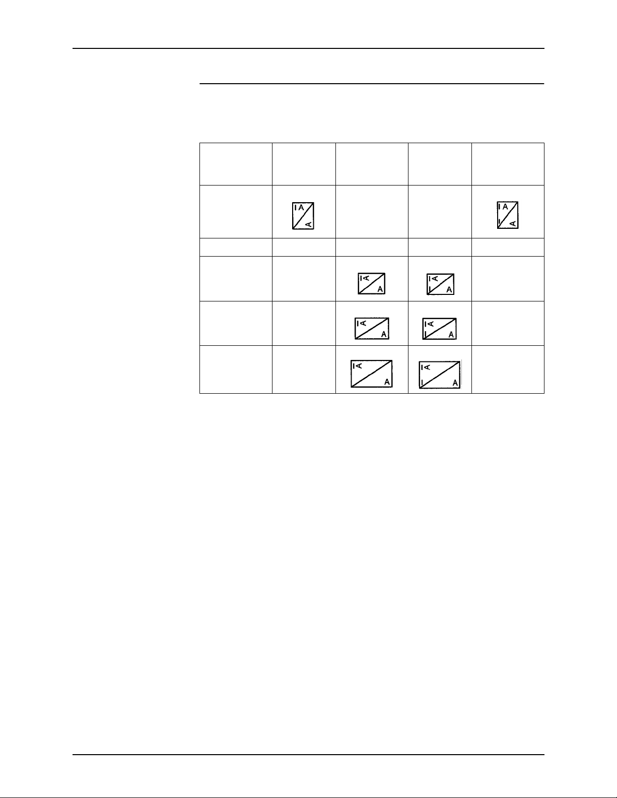
Staple placement
For information about the limitations of portrait and landscape staple
placement, refer to the Staple Placement table below.
Table 3-1. Staple placement
Dual
Edge Feed
Orientation
Long FAULT FAULT
Long N/A N/A N/A N/A
Short FAU LT FAULT
Short FAU LT FAULT
Short FAU LT FAULT
Portrait
Staple
Landscape
Staple
Portrait
Staple
Dual
Landscape
Staple
DocuTech 65/DocuPrint 65 3-9
Page 46
Product overview Installation Planning Guide
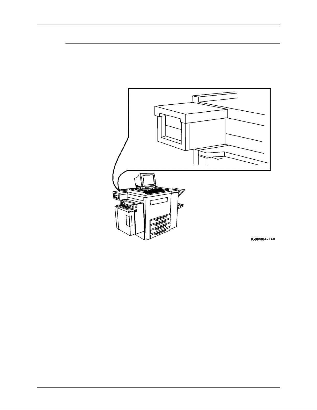
Peripheral hardware components
You may have periphe ral compon ents such as an External SCSI Hard Drive
and an External Tape Drive on a special accessory shelf as shown in Figure
3-7.
Figure 3-7. Special accessory shelf
3-10 DocuTech 65/DocuPrint 65
Page 47

Installation Planning Guide Product overview
Cont ro ller softw ar e
The controller runs the DocuSP Print Services software. This software gives
the printer operator the ability to manage the jobs and the printer. For detailed
information on how to use the DocuSP Print Services software, refer to the
DocuSP on-line Help.
Modems
The controller has an external modem that is on or off according to the site
requirements for this modem or as needed by Xerox service.
The printer has an internal modem that is normally on to enable the Sixth
Sense diagnostics feature or as needed by Xerox service.
DocuTech 65/DocuPrint 65 3-11
Page 48

Product overview Installation Planning Guide
3-12 DocuTech 65/DocuPrint 65
Page 49

4. Maintenance and support services
After the installation of your DocuTech 65/DocuPrint 65 printer, there are a
few ongoing tasks that must be performed. These tasks m ay include all or
some of the following:
• Maintaining an adequate inventory of consumable supplies
• Overseeing routine maintenance and meter reporting
• Arranging additional operator training
• Printing additional documentation
• Placing service calls for hardware problems
Xerox support services
Many services are provided in support of your Xerox printer. This section
contains information on the following services:
• Customer Support Center
• Customer Education
• Supplies Order Service
Prior to installation, your sales representative is available to answer your
questions about products, services, or billing. However , if you need
assistance in resolving application-related problems or questions, call
Customer Support (refer to the following section of this chapter). Your
systems analyst is also available to assist you with applications development.
DocuTech 65/DocuPrint 65 4-1
Page 50

Maintenance and support services Installation Planning Guide
Customer support
The customer support center is available to address your applications
problems or to direct you to the appropriate documentation.
The key to effective use of the support center is correct identification of the
problem. Before calling the support center, it is helpful to have the following
information available:
• A list of any error messages
• An explanation of how output is different from what you expected
• An assessment of whether the symptoms follow a pattern or occur
randomly
• A list of special conditions that may have caused the problem:
– New applications
– Changes made to the software
– Recent service performed
– Pervious conditions under which the application has printed properly
To contact the U.S. Xerox Customer Support Center, call: 1-800-821-2797.
The Xerox Customer Support Center provides 24 hour support.
Operator training
Operator training is conducted either at your location or at a Xerox Customer
Education Center shortly after the printer is installed. The training includes
hands-on practice running basic jobs, performing routine maintenance, and
solving problems. Determine the number of operators you want to attend the
initial training and schedule training dates and times through your sales
representative.
Supplies service
To avoid downtime, always have an adequate amount of the necessary
supplies. T o do this, you need to establish a procedure for checking and
ordering supplies. A supplies checklist is provided at the end of this chapter to
help you with this task. It lists the supplies needed for the printer and contains
a column for you to enter the date when you want to place the order and a
column to record the date of the actual order. The consumable supplies table,
also located at the end of this chapter, contains a list of supplies available for
the printer.
It is important that you check your supplies regularly and order before you run
out. Plan on approximately five working days for the delivery after placing the
order. You can make arrangements to receive them sooner in emergency
situations.
4-2 DocuTech 65/DocuPrint 65
Page 51

Installation Planning Guide Maintenance and support services
Your sales representative can help you submit the initial order of supplies
needed for installation. These items include paper, dry ink, fuser agent, and
developer.
Once your printer volume is established, planning ahead and buying Xerox
supplies in quantity can save you money. Your supply specialists can help
you.
NOTE: The supplies resources listed below are for the United States only.
Multinational customers should contact their local representatives for supplies
ordering information.
Ta b le 4-1. Telephone numbers for orders
Type of Order Number to Call
Supplies USA: (800) 822-2200 (T&M)Canada - English:
(800) 668-0199
Canada - French: (800) 733-9400 (T&M)
Xerox Europe: Contact your local representative.
CRUs USA: (800) 821-2797 (FSMA only)
Canada: (800) 668-0199
Canada - Toronto: (800) 733-9400 (T&M)
Xerox Europe: Contact your local representative.
Please provide the following information when placing orders:
• Your customer number (provided by your sales representative)
• Your printer model
• Your supply order, including the following information:
– Item name
– Part number
– Quantity desired
– If your company requires a purchase order for payment of an invoice,
you need to provide the purchase order number to Xerox at the time
you place the order
DocuTech 65/DocuPrint 65 4-3
Page 52

Maintenance and support services Installation Planning Guide
Routine maintenance
There are a number of routine maintenance tasks that must be performed to
ensure maximum efficiency of your printer. These tasks include the following:
• Replacing the Customer Replaceable Units (CRUs) as necessary
• Cleaning the exterior surfaces of the system
Step-by-step instructions on performing these routine maintenance ta sks ar e
contained in your DocuTech 65/DocuPrint 65 Operator Guide.
You need to decide how many operators will be responsible for performing
these maintenance tasks. Most maintenance procedures are covered in the
initial operator training provided shortly after installation.
Meter reading and reporting
As print jobs are processed, the DocuSP controller accumulates, saves, and
maintains usage data.
During the last five working days of each month, you need to review and
transmit the data to Xerox for billing purposes.
Refer to the section on Billing in the Help on the DocuSP controller for
complete information on how to view and print the billing meter readings.
Consum able supplies tables
The following tables list the supplies that are available from Xerox for your
printer. Use t hes e tables to help you determine your nee ds.
The following symbols are used in the consumable supplies able:
* 5/16-inch drilled holes
** Rainbow pack contains 750 sheets each of blue and yellow, 500 sheets
each of green and pink, and 250 sheets each of buff, gray, goldenrod, and
ivory.
4-4 DocuTech 65/DocuPrint 65
Page 53

Installation Planning Guide Maintenance and support services
NOTE: Non-United States customers: The part numbers in this table are for
the United States only. Contact your local representative for supplies ordering
information.
Tab le 4-2. Life expectancy for CRUs and consumable supplies
Item Description and Life Expectancy Part Number
Fuser C RU 108R148 USA and Canada
108R150 XE or DMO Latin
400K imps.hard stop, 310K average
Note: DocuT ech 65/DocuPrint 65 ignores the
hard stop but displays a CRU message.
Xerographic CRU (Includes one Developer Collector)
200K imps. hard stop
Note: DocuTech 65/DocuPrint 65 ignores the
hard stop but displays a CRU message.
USA and Canada:
FSMA 109R330 N/A
T&M 109R329
XE:
65PPM FSMA109R334
65PPM Sold 109R333
DMO Latin:
65PPM/115V FMSA 109R345
65PPM/115V Sold 109R344
65PPM/230V FMSA 109R341
65PPM/230V Sold 109R340
USA and Canada:
FSMA 113R1 32 N/A
T&M 113R131
XE:
FSMA 113R134
Sold 113R133
Paper Feed Roll
All paper tray feeders are 100-125K feeds. USA and Canada:
Cartridge CRU
Dry Ink (Toner) 2 Pack (contains 2 cartridges)
6 Pack (contains 6 cartridges)
XL 6 Pack (contains 6 cartridges)
Each cartridge yields 21.7K at 6% coverage.
DMO Latin:
FMSA 113R175
Sold 113R174
FSMA 108R148 N/A
T&M N/A*
XE and DMO Latin:
108R150
USA, Canada, and DMO Latin:
6R849 for 2 Pack
6R821 for 6 Pack
XE:
6R90252 for 6 Pack
DocuTech 65/DocuPrint 65 4-5
Page 54

Maintenance and support services Installation Planning Guide
Tab le 4-2. Life expectancy for CRUs and consumable supplies
Item Description and Life Expectancy Part Number
Staple Cartridge Each cartridge contains 5K staples.
3 Pack contains 3 cartridges
* Obtain the Paper Feed Roll Cartridge through the Xerox service
representative.
World wide:
108R53 for 3 Pack
4-6 DocuTech 65/DocuPrint 65
Page 55

Installation Planning Guide Maintenance and support services
Tab le 4-3. Consum ab le supplies
U.S. part
Item Description
number
Paper Xerox paper quantities are 10
reams (5,000 sheets) to a carton
unless otherwise noted below
8.5 x 11 inch 4024 Dual Purpose Paper 3R721
A4 4024 Dual Purpose Paper 3R2594
8.5 x 14 inch 4024 Dual Purpose Paper 3R727
8.5 x 11 inch 4024 Dual Purpose Paper, 3-hole 3R723
8.5 x 11 inch 4024 Dual Purpose Paper, 3-hole* 3R2193
8.5 x 11 inch 4024 Dual Purpose Paper, 4-hole 3R1983
8.5 x 11 inch 4024 Dual Purpose Paper, 4-hole* 3R3008
8.5 x 11 inch 4024 Dual Purpose Paper, 7-hole 3R1984
8.5 x 11 inch 4024 Dual Purpose Paper, 7-hole* 3R3010
8.5 x 11 inch 4024 Smooth 3R2675
8.5 x 14 inch 4024 Smooth 3R2677
8.5 x 11 inch Dual Purpose Colors, Blue 3R3052
8.5 x 11 inch Dual Purpose Colors, Blue, 3-hole 3R3068
8.5 x 14 inch Dual Purpose Colors, Blue 3R3084
8.5 x 11 inch Dual Purpose Colors, Green 3R3056
8.5 x 11 inch Dual Purpose Colors, Green, 3-
3R3072
hole
8.5 x 14 inch Dual Purpose Colors, Green 3R3088
8.5 x 11 inch Dual Purpose Colors, Pink 3R3058
8.5 x 11 inch Dual Purpose Colors, Pink, 3-hole 3R3074
8.5 x 14 inch Dual Purpose Colors, Pink 3R3090
8.5 x 11 inch Dual Purpose Colors, Yellow 3R3054
8.5 x 11 inch Dual Purpose Colors, Yellow, 3-
3R3070
hole
8.5 x 14 inch Dual Purpose Colors, Yellow 3R3086
8.5 x 11 inch Dual Purpose Colors, Buff 3R3060
8.5 x 11 inch Dual Purpose Colors, Buff, 3-hole 3R3076
8.5 x 14 inch Dual Purpose Colors, Buff 3R3092
8.5 x 11 inch Dual Purpose Colors, Goldenrod 3R3062
8.5 x 11 inch Dual Purpose Colors, Goldenrod,
3R3078
3-hole
DocuTech 65/DocuPrint 65 4-7
Page 56

Maintenance and support services Installation Planning Guide
Tab le 4-3. Consum ab le supplies
U.S. part
Item Description
number
8.5 x 14 inch Dual Purpose Colors, Goldenrod 3R3094
8.5 x 11 inch Dual Purpose Colors, Ivory 3R3064
8.5 x 11 inch Dual Purpose Colors, Ivory, 3-hole 3R3080
8.5 x 14 inch Dual Purpose Colors, Ivory 3R3096
8.5 x 11 inch Dual Purpose Colors, Gray 3R3066
8.5 x 11 inch Dual Purpose Colors, Gray, 3-hole 3R3802
8.5 x 14 inch Dual Purpose Colors, Gray 3R3098
8.5 x 11 inch** Dual Purpose Colors, Rainbow
3R3107
Pack 35,000 sheets/carton - 250
sheets/pack**
8.5 x 11 inch 10 Series Dual Purpose Paper 3R2950
8.5 x 11 inch 10 Series Dual Purpose Paper, 3-
3R2952
hole
8.5 x 11 inch 10 Series Dual Purpose Paper, 3-
3R3016
hole*
8.5 x 14 inch 10 Series Dual Purpose Paper 3R2954
8.5 x 11 inch 10 Series Smooth 3R54
8.5 x 14 inch 10 Series Smooth 3R83
8.5 x 11 inch 4024 Dual Purpose, reinforced 3-
3R2057
hole
Image LX (Laser
Xerographic Paper)
Image LX White 8.5 x 11 inch 3-hole (5000
White 8.5 x 11 inch (5000 sheets/
carton
3R3874
3R3875
sheets/carton)
Image LX White 8.5 x 14 inch (4000 sheets/
3R3876
carton)
Image LX White 11 x 17 inch (4000 sheets/
3R3877
carton)
Transparencies Xerox transparencies are
packaged 100 sheets to a box
8.5 x 11 inch Clear, with a white strip on the
3R2780
edge
Labels ( Gu m m e d) Xerox labels are packaged 100
sheets to a box
8.5 x 11 inch 33 labels per sheet 3R3139
8.5 x 11 inch 6 labels per sheet 3R3146
4-8 DocuTech 65/DocuPrint 65
Page 57
Installation Planning Guide Maintenance and support services
Tab le 4-3. Consum ab le supplies
U.S. part
Item Description
8.5 x 11 inch Custom form (uncut) Contact Xerox
Cleaning supplies Lint-free towels 35P2163
Cartridge tape 4 mm blank cartridge, 8 GB 109R00314
number
Supplies
Order Service
Diskettes 3.5 inch, double sided, dual
density, 1.44 MB, unformatted.
Packaged 10 per box.
Dry ink (toner) and “dry ink low” message
Dry ink (toner) usage is related to the amount of area that needs to be printed
(covered). The greater the area of coverage, the more dry ink used; for
example, a typical office memo would have these approximate values:
• text only - 6% area coverage
• a solid area of 1 x 2 inches (25 x 51 mm) - 8% area coverage
• a solid area of 1.25 x 7.5 inches (32 x 191mm) that is 8.75% of the memo
area - 15% area coverage.
Table 3 shows the dry ink usage and area coverage. For example, at 6% area
coverage, the system will produce approximately 21,700 prints. This
information will help you estimate how long it will be before the system
displays a “dry ink low” message.
Table 4-4. Dry ink (toner) usage and area coverage
AREA
COVERAGE
PRINTS PER
CARTRIDGE
8R3704
PRINTS PER
CARTON -
2 PACK
6R849
PRINTS PER
CARTON -
6 PACK
6R821
4% 30,400 60,800 182,400
5% 25,000 50,000 150,000
6% 21,700 43,400 130,200
7% 19,100 38,200 114,600
8% 17,100 34,200 102,600
9% 15,400 30,800 92,400
10% 14,000 28,200 84,600
15% 9,700 19,400 58,200
DocuTech 65/DocuPrint 65 4-9
Page 58

Maintenance and support services Installation Planning Guide
Supplies checklist
Use the following table to help record the supplies and accessories you
require, the date on which the order should be placed, and the actual date of
the order.
4-10 DocuTech 65/DocuPrint 65
Page 59

Installation Planning Guide Maintenance and support services
Table 4-5. Supplies checklist
Item Description Quantity Date of order Date ordered
Paper
Fuser CRU
Xerographic CRU
Paper Feeder CRU
Paper Feed Roll
Cartridge
Dry Ink (Toner)
Staple Cartridge
Labels
Transparencies
Cleaning supplies
Other
DocuTech 65/DocuPrint 65 4-11
Page 60

Maintenance and support services Installation Planning Guide
4-12 DocuTech 65/DocuPrint 65
 Loading...