

Page 1

Document Centre
400/350/250 Series
User Guide (Printer)
All Contents and Index entries are in hypertext link.
Click on them to be transported to the corresponding page.
Page 2

AppleTalk, EtherTalk, TrueType, Apple and Macintosh are trademarks of Apple Computer, Inc.
registered in the US and other countries.
Adobe, Adobe Type Connection, Adobe Type Manager, PostScript, PostScript 3, and the PostScript
logo are trademarks of Adobe Systems Incorporated.
Helvetica, Palatino, Times are trademarks of Linotype-Hell, AG.
Microsoft, MS-DOS, Windows, Windows NT are registered trademarks of Microsoft Corporation in
the U.S. and other countries.
NetWare is a registered trademark of Novell, Inc.
UNIX is a trademark of X/Open Company Ltd.
All product/brand names are trademarks or registered trademarks of the respective holders.
Permission has been obtained from Microsoft Corporation for use of software screen shots.
Important
This manual is copyrighted with all rights reserved. Under the copyright laws, this manual may not be copied,
in whole or part without the written consent of the publisher.
Parts of this manual are subject to change without prior notice.
We welcome any comments on ambiguities, errors, omissions, or missing pages.
Never attempt any procedure on the machine that is not specifically described in this manual.
Unnauthorized operation can cause faults or accidents. Fuji Xerox is not liable for any problems resulting from
unauthorized operation of the equipment.
XEROX is a registered trademark.
The Document Company and Ethernet are trademarks which may be registered in certain
jurisdictions.
CentreWare is a trademark.
Page 3

Preface
Welcome to Xerox Document Centre 400/350/250 series.
Written with the new user in mind, this User Guide (Printer) provides all the necessary information about
operating the printer functions of the printer as well as installing the printer drivers. To get the most out of
the machine, please read this manual before using it.
This guide is written with the assumption that you are familiar with the basic knowledge and way of
operating the different operating systems. Refer to the manuals of these products for information on
them.
Note that this guide is written for users operating the Document Centre 400/350/250 series with a client
computer installed with an English edition operating system. Unless otherwise indicated, this guide is
written for use with English edition operating system only.
After reading, keep this guide handy for a quick reference should you encounter any difficulties when
using the machine.
In this manual, safety instructions are described with the symbol . Always read and follow these instructions
before performing the required procedure.
This product is in the Class B category based on the standard of Voluntary Control Council for Interference from
Information Technology Equipment (VCCI)*. If the machine is used near a radio or television receiver in a
domestic environment, it may cause radio interference. Install and use the machine according to the instructions.
* This regulation applies only to Japan.
This equipment conforms to the guidelines of the Japan Business Machine Makers Association on the
harmonic effects by copiers and other reproduction devices. These guidelines conform to the guides on the
harmonic suppressors of electronic appliances and general-purpose machines.
i
Page 4

Types of Manuals
The types of manuals available for the Document Centre 400/350/250 series are as follows:
Manual bundled with the main unit (i.e. the copier)
• User Guide (Copier)
Explains the handling of the copier and the copier functions.
Manuals bundled with the fax kit/fax-installed unit
• User Guide (Facsimile)
Explains the fax functions.
• Quick Reference
A simple manual which gives a summary of some of the fax functions which have
raised the most queries in the past.
Manual bundled with the printer kit/printer-installed unit
• User Guide (Printer) - i.e. this manual
Explains the printer functions, the printer control panel operations as well as the installation/
configuration of the PCL printer drivers.
Manuals bundled with the optional accessories
Manuals on the handling and use of the accessories.
ii
Page 5

Using This Guide
Organization
The following is a summary of each chapter:
Chapter 1 Overview of the Printer
This chapter explains the interface connections, special features, printer functions and
powering on/off.
Chapter 2 Setting Up
This chapter explains the cable connections and the increase/allocation of memory.
Chapter 3 Useful Operations
This chapter explains the operations that you need to know about using the printer
functions such as as cancelling printing/fax transmission, outputting and the main frame
control panel operations during printing/transmission.
Chapter 4 Installing/Configuring the Printer Drivers
This chapter explains how to install printer drivers, set the printer properties, print
and fax from an application in different OS environments.
Chapter 5 Mode Menu/Common Menu
This chapter explains about the two menus, Mode menu and Common menu and their
menu items.
Chapter 6 Precautions and Limitations
This chapter explains the precautions and limitations of using the printer.
Chapter 7 Troubleshooting
This chapter explains how to solve problems when the printer is not functioning
properly. When problems occur, read this first before treating it as a breakdown.
iii
Page 6

Appendix
This section provides information on the printing area, connector and allocation signals, the
different items of the Print Utility, paper jams at the mail box as well as the PostScript 3
Kit.
Glossary
This section explains the meanings of the terms used in this guide.
System Charts
This section contains the system charts of the menus. Refer to these charts to make
changes to the settings after you have understood the printer operations.
iv
Page 7
Conventions
1. In this manual, a host device refers to a personal computer or workstation and
2. The following icons are used in this guide:
Instructions or important information for preventing equipment damage.
3. The following conventions are used in this guide.
"Xerox DC 400/350/250" refers to "Xerox Document Centre 400/350/250".
For your information. This indicates additional information on procedures of
operations and features.
Indicates sources of references.
" " : Double quotes are used to indicate names of windows, menus, dialog boxes,
icons, files, tabs, fields and input contents.
For example: The "Select a Printer" dialog box appears.
Bold Face : Bold face characters refer to selections made like options on the screen, hard
or soft buttons, and keys from the keyboard.
For example: Press Esc.
v
Page 8

Contents
Preface ................................................................................................................................................................ i
Types of Manuals .............................................................................................................................................. ii
Using This Guide .............................................................................................................................................. iii
Contents ........................................................................................................................................................... vi
Safety Precautions ............................................................................................................................................. ix
Chapter 1 Overview of the Printer
1.1 Getting Ready to Print ............................................................................................................................ 2
1.2 Special Features of the Printer ................................................................................................................ 4
1.3 Main Components and Their Functions ................................................................................................ 5
1.3.1 Parts of the printer configuration ................................................................................................ 5
1.3.2 Control panel .............................................................................................................................. 7
1.3.3 CD-ROM ................................................................................................................................... 12
1.4 Precautions on Switching On/Off ......................................................................................................... 13
Chapter 2 Setting Up
2.1 Connecting Cable (Parallel/Serial Interface) ......................................................................................... 16
2.1.1 Connecting interface cable ....................................................................................................... 16
2.2 Using the Ethernet Interface ................................................................................................................ 20
2.2.1 Installing the Ethernet interface card ........................................................................................ 20
2.2.2 Connecting the Ethernet interface ............................................................................................ 21
2.3 Increase/Allocation of Memory ........................................................................................................... 23
2.3.1 Uses .......................................................................................................................................... 23
2.3.2 Suggested values...................................................................................................................... 23
Chapter 3 Useful Operations
3.1 Flow of Printing/Fax Transmission ....................................................................................................... 26
3.1.1 For Windows ............................................................................................................................ 26
3.1.2 For DOS (printing only) ............................................................................................................ 27
3.2 Cancelling Printing/Fax Transmission .................................................................................................. 28
3.2.1 Cancelling from host device...................................................................................................... 28
3.2.2 Cancelling jobs in process ........................................................................................................ 29
3.2.3 Cancelling all jobs in the printer................................................................................................ 29
3.2.4 Cancelling fax transmission from touch panel display .............................................................. 30
3.3 Outputting............................................................................................................................................ 31
3.3.1 Forced outputting of remaining print data ................................................................................ 31
3.3.2 Outputting all jobs in the printer ............................................................................................... 32
3.4 Main Frame Control Panel Operations During Printing/Transmission ................................................. 33
3.5 Removing Documents Output to the Stacker Tray............................................................................... 34
3.6 Outputting Lists/Reports ..................................................................................................................... 35
3.6.1 Types of lists/reports ................................................................................................................ 35
3.6.2 Printing lists/reports ................................................................................................................. 35
3.7 Printer Functions .................................................................................................................................. 37
vi
Page 9

Chapter 4 Installing/Configuring the Printer Drivers
4.1 About the Printer Drivers ..................................................................................................................... 40
4.1.1 The PCL 5e/PCL 6 printer drivers .............................................................................................. 40
4.1.2 Installation/configuration methods........................................................................................... 40
4.1.3 Settings on the Xerox DC 400/350/250 printer ........................................................................... 40
4.2 Installing/Uninstalling the Printer Drivers ............................................................................................ 41
4.2.1 For a local Xerox DC 400/350/250 printer .................................................................................. 41
4.2.2 For a network Xerox DC 400/350/250 printer ............................................................................. 43
4.2.3 Uninstalling the printer drivers ................................................................................................. 44
4.3 Configuring the Printer Drivers ............................................................................................................ 46
4.3.1 Accessing the printer properties dialog box ............................................................................. 46
4.3.2 Setting the printer properties .................................................................................................... 49
4.4 Printing/Faxing ..................................................................................................................................... 73
4.4.1 Printing from an application ...................................................................................................... 73
4.4.2 Faxing from an application ........................................................................................................ 73
Chapter 5 Mode Menu/Common Menu
5.1 Mode Menu and Common Menu ......................................................................................................... 80
5.1.1 About menu .............................................................................................................................. 80
5.1.2 Mode menu ............................................................................................................................... 81
5.1.3 Common menu .......................................................................................................................... 82
5.2 Mode Menu Items ................................................................................................................................ 84
5.2.1 List of Mode Menu items ..........................................................................................................84
5.2.2 Setting a Mode Menu ............................................................................................................... 89
5.3 Common Menu Items ........................................................................................................................... 90
5.3.1 List of Common Menu items ..................................................................................................... 90
5.3.2 Setting a Common Menu ......................................................................................................... 103
Chapter 6 Precautions and Limitations
6.1 Precautions and Limitations ................................................................................................................ 106
Chapter 7 Troubleshooting
7.1 When Problems Occur ........................................................................................................................ 110
7.2 Messages ............................................................................................................................................ 114
7.2.1 Messages about printer condition ........................................................................................... 114
7.2.2 Messages about operation mistakes and breakdowns ............................................................ 116
7.2.3 Messages about staple finisher ............................................................................................... 121
7.3 When the Print Quality is Poor............................................................................................................ 123
Appendix
A Printing Area .......................................................................................................................................128
B Connector and Allocation Signals ...................................................................................................... 129
B.1 Parallel Interface .......................................................................................................................129
B.2 Serial Interface ......................................................................................................................... 131
vii
Page 10

C Print Utility .......................................................................................................................................... 133
C.1 Types and Paper Sizes ............................................................................................................. 133
C.2 PCL6 Settings...........................................................................................................................134
C.3 Printer Settings ........................................................................................................................ 136
C.4 Error History ............................................................................................................................ 138
C.5 Print History.............................................................................................................................140
C.6 Job Template Server Settings ...................................................................................................143
C.7 PCL6 Font List ......................................................................................................................... 145
C.8 PS Font List..............................................................................................................................148
D Mail Box Paper Jams ............................................................................................................................151
E PostScript 3 Kit.................................................................................................................................... 152
E.1 Setting Up the Printer ............................................................................................................... 152
E.2 Precautions and Limitations..................................................................................................... 154
Glossary.......................................................................................................................................................... 156
System Charts (Mode Menu Items)................................................................................................................ 158
System Charts (Common Menu Items) ...........................................................................................................161
Index ............................................................................................................................................................168
viii
Page 11
Safety Precautions
Read these safety notes before using the printer functions of this machine.
Conventions and symbols
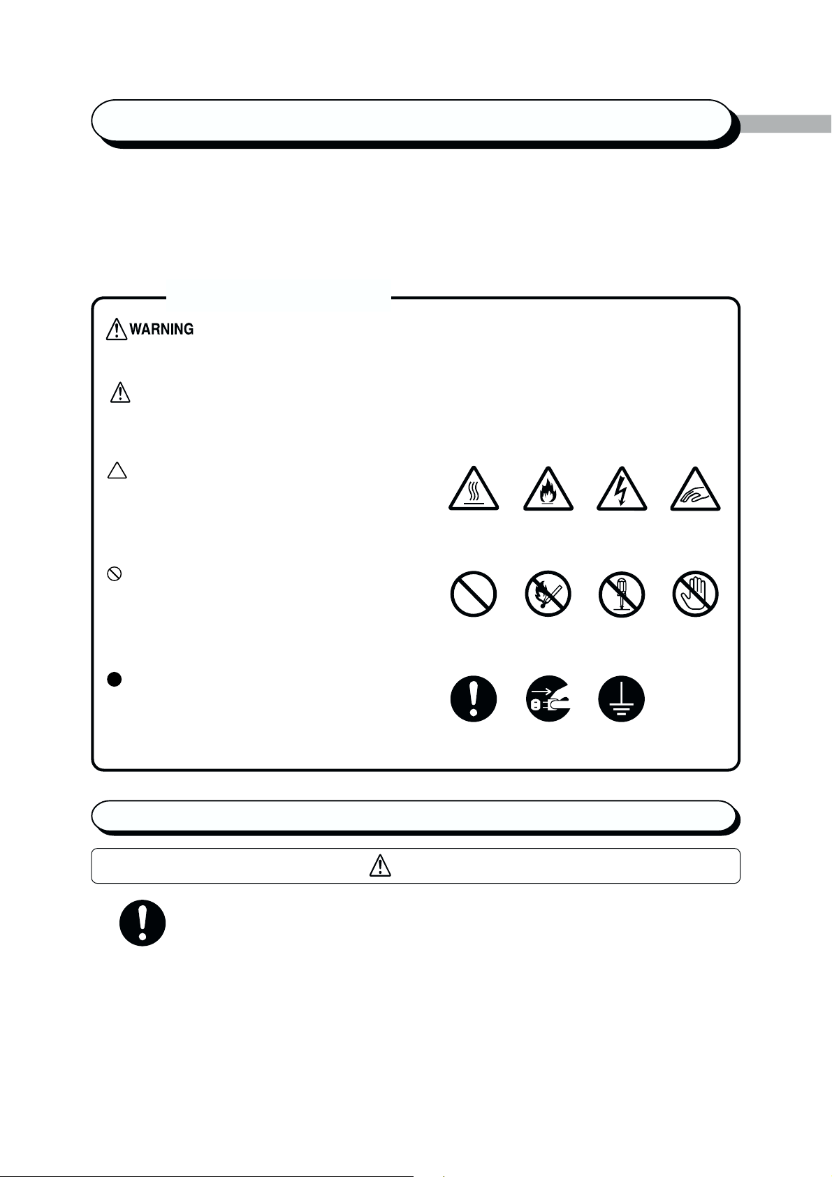
is used to alert operators to an operating procedure, practice or condition that, if not
strictly observed, can result in severe injury or loss of life.
CAUTION
is used to alert operators to an operating procedure, practice or condition that, if not
strictly observed, might result in safety hazards to personnel or damage to the equipment.
This symbol is used to alert operators to a specific
operating procedure that requires close attention.
Read and follow instructions carefully to ensure the
task is accomplished safely.
This symbol is used to alert operators to a specific
operating procedure that must not be performed.
Read and follow instructions carefully.
This symbol is used to alert operators to a specific
operating procedure that should be emphasised for
operating safety. Read and follow instructions
carefully.
Heated Flammable Electric Pinched
surface shock fingers
Prohibited! No fire Do not Do not
tear down touch
Instructions Unplug Ground/Earth
Precaution for power and earth connection
CAUTION
When connecting interface cable, make sure that the power of the main frame and host device is
switched off to prevent the possibility of electricity shock.
ix
Page 12
Precaution for switching off the power
When switching off the power for Xerox DC 400/350/250 series models with fax functions,
check that the Document In Memory indicator light on the main frame control panel is off.
If the power is switched off while the light is on, document data spooled in the memory will
be erased.
• After being charged for 72 hours, this machine is able to keep the contents in
memory for three hours.
• If the Document In Memory indicator light is lit, check if there is any "Received
document". If yes, follow the instruction on display and output it. Otherwise, output
the list of stored document and check the contents.
When the power is switched off, print data remaining in the printer kit and information
spooled in the memory of the printer kit will be erased. Before switching off the power
during operation, check that the message "Ready" is shown on the display of the control
panel.
The memory used by the printer belongs to the printer kit, which is different from
those used by the copy and fax functions. However, when the power is switched off,
data will be erased from the memory.
x
Page 13

Overview of the
Printer
1.1 Getting Ready to Print........................................................................... 2
1.2 Special Features of the Printer.............................................................. 4
1.3 Main Components and Their Functions................................................ 5
1.4 Precautions on Switching On/Off ....................................................... 13
Page 14
1.1 Getting Ready to Print
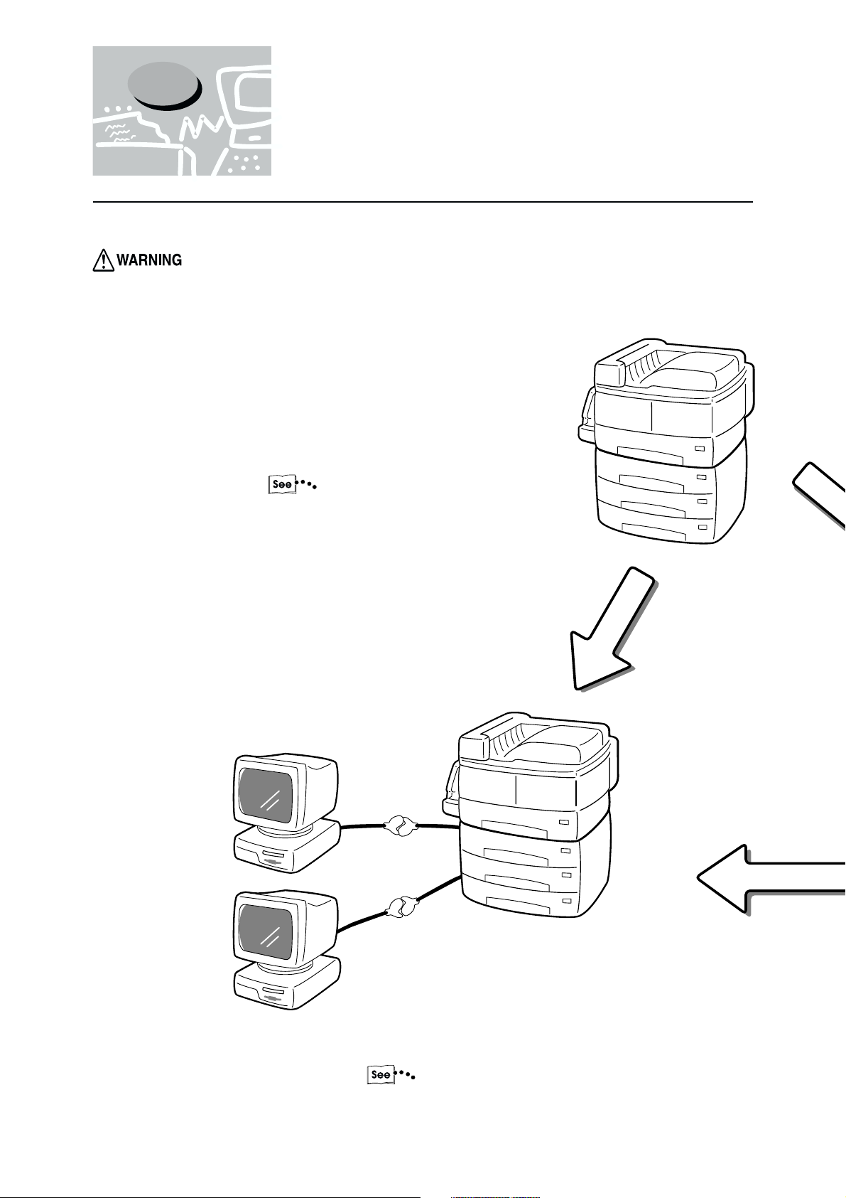
This section explains the procedure for setting up the printer. The flow of operations is as follows:
1
Check that the printer is switched off before handling it. If not, there is a danger of electric shock.
Connect the cable and allocate memory.
"Chapter 2 Setting Up"
When connecting to the
host device directly
Parallel
Serial
Carry out the necessary installation and
setting to the host device.
The printer control panel also needs to be
set.
"Chapter 4 Installing/Configuring the
Printer Drivers"
2
Page 15
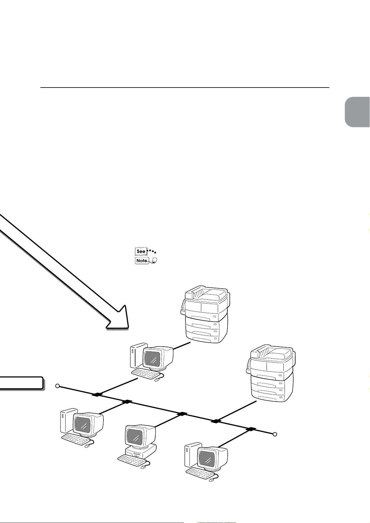
1.1 Getting Ready to Print
When the printer is used via a network, it is necessary to set the
different types of servers and printer control panels.
"Network Print Environment User Guide" regarding these settings.
It is suggested that the memory be increased.
1
Overview of the Printer
When connecting to
network
3
Page 16

1
1.2 Special Features of the
Printer
This printer kit can be used as a network-compatible printer that can be connected directly to the
network.
It can be installed with multi-emulation.
The special features of the printer are as follows:
• It is installed with PCL 6 emulation. PostScript emulation is an optional feature.
• Printing can be specified without having to take into consideration the printer language as there is an
automatic printer language detection feature (applicable only when more than one emulation is
installed).
• High quality printing can be achieved with its 400/600 dpi laser-style resolution.
Also, it comes with an image-enhancement feature which can increase resolution and produce smooth
printing without any notches (equivalent to 2400 dpi).
• Besides the standard parallel and serial interfaces, it can be used in network (multi-protocol)
environment through the installation of interface card.
• All the interfaces installed can receive data at the same time.
• Double-sided printing can be done by installing a duplex unit.
• Multiple-copies sorting can be achieved through the electronic sorting feature (when installing the hard
disk). Also, there is no need to rearrange pages as pages can be output with the printed side facing up
without interrupting the page order.
• Direct fax mailing from the network host installation can be done by using the printer with the fax
feature. Also, data read from the main frame can be imported from the network host installation.
• DPI is the abbreviation of Dot Per Inch and is the unit that indicates the number of dots that
can be printed within a one-inch area. It is used as a unit indicating resolution.
• Protocol is the essential communcation regulation for carrying out data transmission.
4
Page 17
1.3 Main Components and
Their Functions
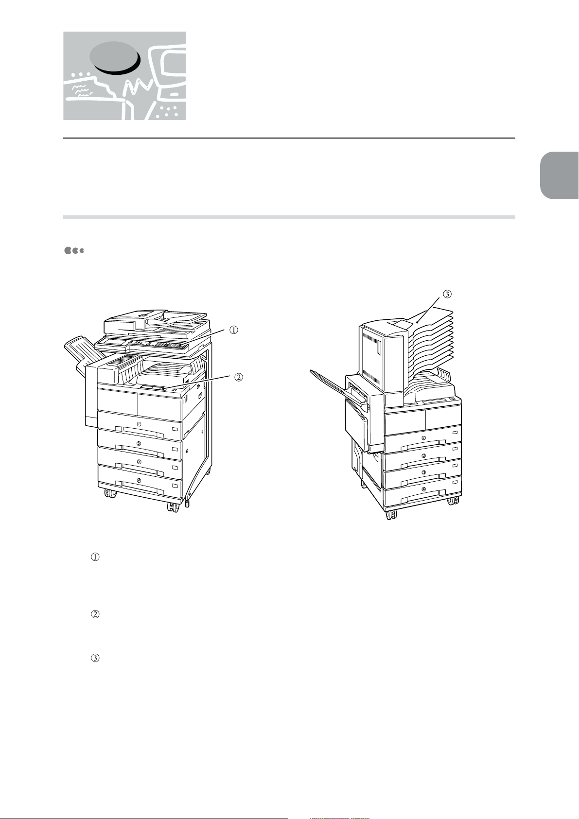
The names of the various parts of the printer are provided below. For other parts, see "1-1 Main Components and Their Functions" of the User Guide (Copier).
1
1.3.1 Parts of the printer configuration
Front view
Main frame
control panel
Printer control
panel
Overview of the Printer
Mail box
Main frame control panel
Utilise this when using the copier and fax functions of the machine. If necessary, it will display
the message, "Printing" when the printer function is being used.
Printer control panel
Utilise this when using the printer function of the machine.
Mail box
This output device is an optional item. With the mail box attached, documents can be output to a
specified bin to prevent documents output from multiple users from being mixed up.
5
Page 18
1
1.3 Main Components and Their Functions
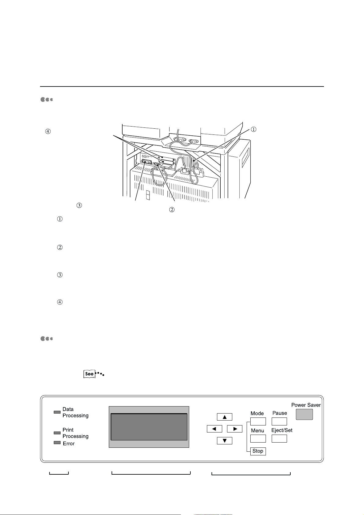
Rear view
Slot for expansion interface
Parallel interface connector
Serial interface connector
Ventilation opening
Ventilation opening
Ventilation opening for the cooling fan.
Serial interface connector
Connects printer to host device by a RS-232C interface cable.
Parallel interface connector
Connects printer to host device by a centronics/IEEE 1284-compliant interface cable.
Slot for expansion interface
For attaching optional interface cable.
Printer control panel
The printer control panel is shown below. Check the position of the LED, Display and the
various keys.
“1.3.2 Control panel”
LED Display Keys
6
Page 19
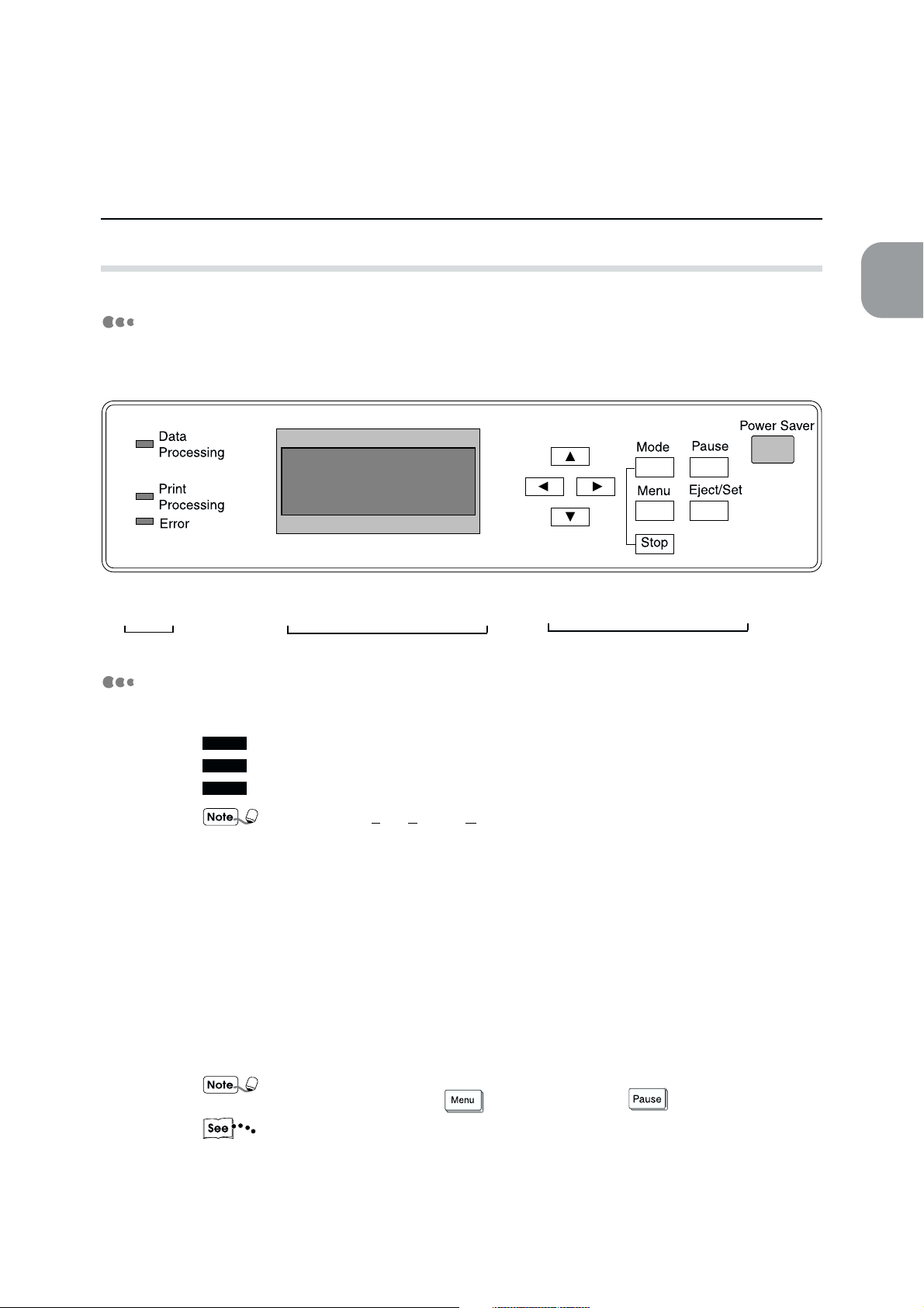
1.3.2 Control panel
1.3 Main Components and Their Functions
1
Parts
The control panel consists of the LED, Display and the keys.
LED Display Keys
LED
LED indicates printer state by turning on, blinking and turning off light.
Data Processing
Print Processing
Error
Overview of the Printer
LED stands for Light Emitting Diode.
Data Processing
Indicates the state of data processing by green light.
• Light on
Ready to receive data.
• Blink
Receiving data.
• Light off
Unable to receive data.
When data cannot be received, it could be due to instances when you have accessed the
Common menu by pressing
"Chapter 5 Mode Menu/Common Menu" for details on the menu operations. Also, for
information on the Pause Mode, refer to "3.2.3 Cancelling all jobs in the printer" and
"3.3.2 Outputting all jobs in the printer".
or the Pause Mode by .
7
Page 20
1
1.3 Main Components and Their Functions
Print Processing
Indicates the state of print/fax processing by green light.
• Light on
Processing print/fax data.
• Blink
Waiting for data during printing process.
• Light off
Not processing print/fax data.
Error
Indicates state of printer abnormality by red light.
• Light on
A problem that can be handled by the user, such as paper jam.
• Blink
A problem that cannot be handled by the user. Contact the Xerox Customer Support
Centre.
• Light off
No problem. The printer is functioning properly.
Display
"7.2 Messages" for information on the messages displayed when there is an error.
The display shows messages indicating the printer state as well as its setting state.
Depending on whether the options are installed, the state of the setting and the
printer model, some messages may not be displayed.
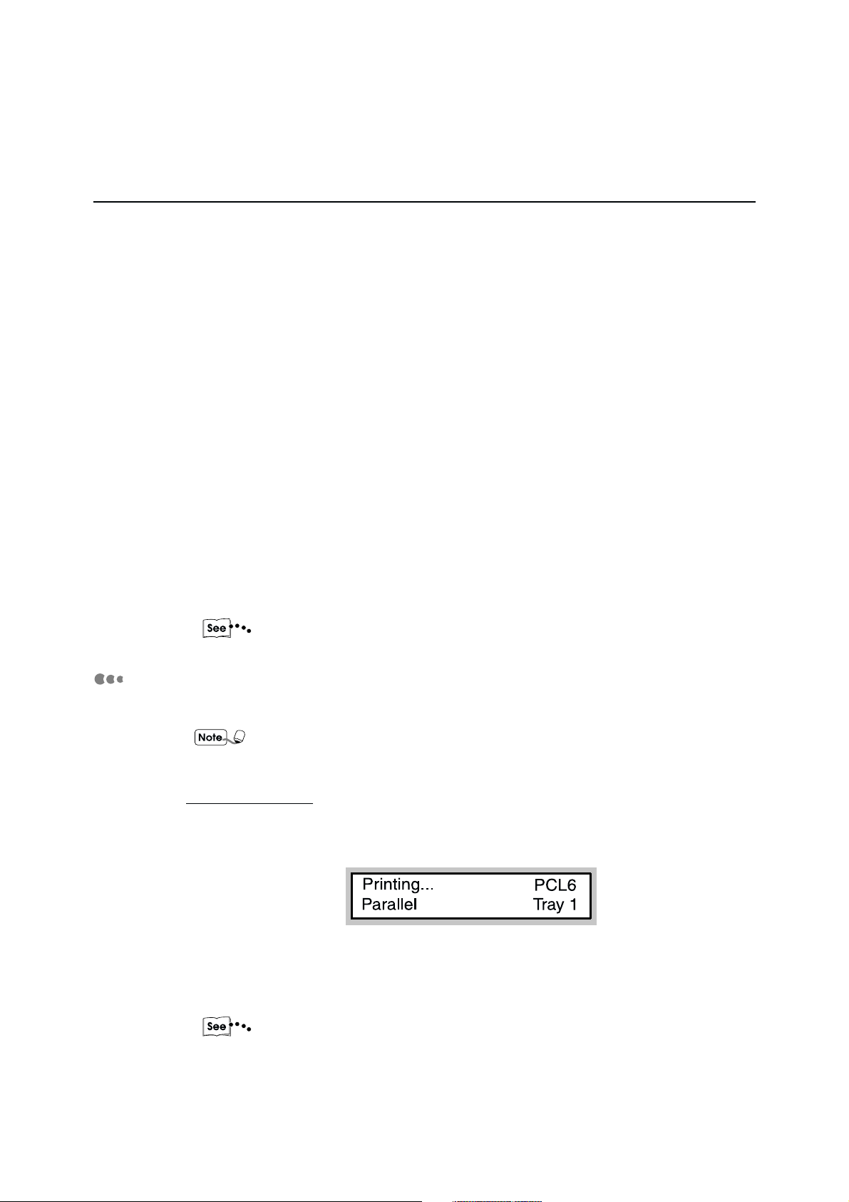
For the Print screen
While printing/faxing or waiting for data, the display will show the Print screen which
indicates the state of the printer as well as of the ongoing data processing.
Printer state
Indicates the state of the printer. Messages include "Please wait", "Ready", "Printing",
"Cancelling" and "Data wait".
"7.2 Messages" regarding the messages.
Mode
Indicates the type of print mode. At the moment, only "PCL6" is available.
8
Page 21
1.3 Main Components and Their Functions
Input Port
Indicates the input port that receives data. Messages include "Parallel", "Serial",
"EtherTalk", "lpd/PD" and "NetWare".
Tray
Indicates the paper tray for printing. Messages include "Tray 1", "Tray 2", "Tray 3", "Tray
4", "BPT", "HCF1", "HCF2" and "Auto".
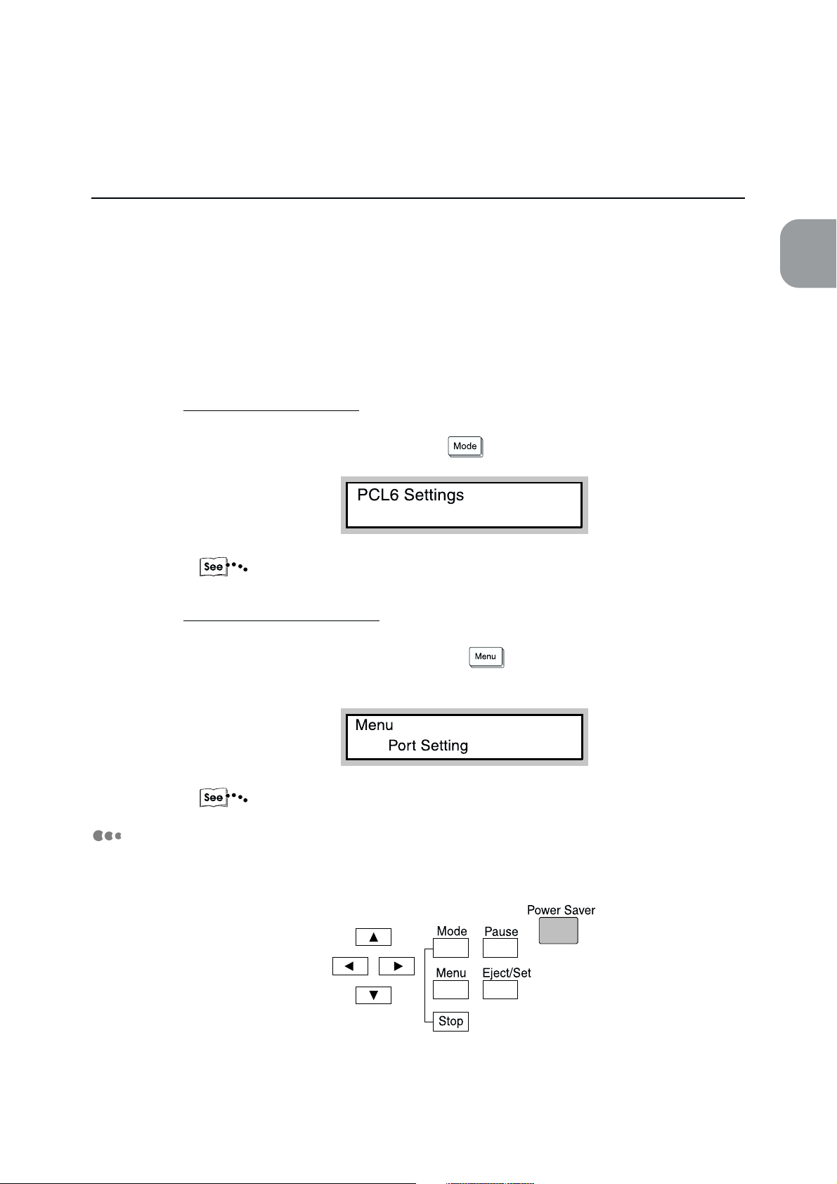
For the Mode Menu screen
The screen to fix setting for emulation processing.
To display the Mode Menu screen, press
"5.2.2 Setting a Mode Menu"
.
1
Overview of the Printer
Keys
For the Common Menu screen
The screen to set items common to all print modes.
To display the Common Menu screen, press .
The Port Setting screen is displayed as follows:
"5.3.2 Setting a Common Menu"
There are nine keys on the printer control panel:
9
Page 22
1.3 Main Components and Their Functions
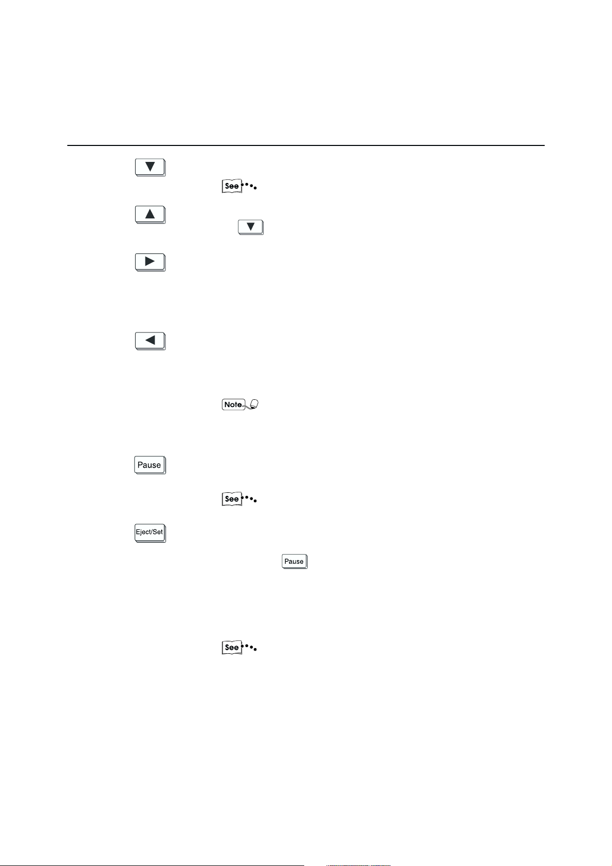
Displays in order, menu, menu item, item and candidate value.
1
"5.1 Mode Menu and Common Menu"
Displays menu, menu item, item and candidate value in the reverse order
of
Moves from menu to menu item, menu item to item, item to candidate
value.
Also, moves the cursor value of the candidate value to the right one place
at a time.
Moves from menu item to menu, item to menu item, candidate value to
item.
Also, moves the cursor of the candidate value to the left one place at a
time.
Moves to pause state. At this state, no data can be received and no
printing can be processed.
.
Moves cursor when at the top extreme left of the display to the
bottom extreme right as well as when at the bottom extreme left to
the top extreme right.
"3.2.3 Cancelling all jobs in the printer" and "3.3.2 Outputting
all jobs in the printer" for details on the pause state.
Eject
Remaining data will be forcibly processed and printed. Also, when used
together with
printed.
Set
Sets the candidate value of the menu operation. Also carries out
operations like Print Utility, Echo Back Mode.
"3.3 Outputting" for details on the outputting operations.
, all print jobs in the printer will be processed and
10
Page 23
1.3 Main Components and Their Functions
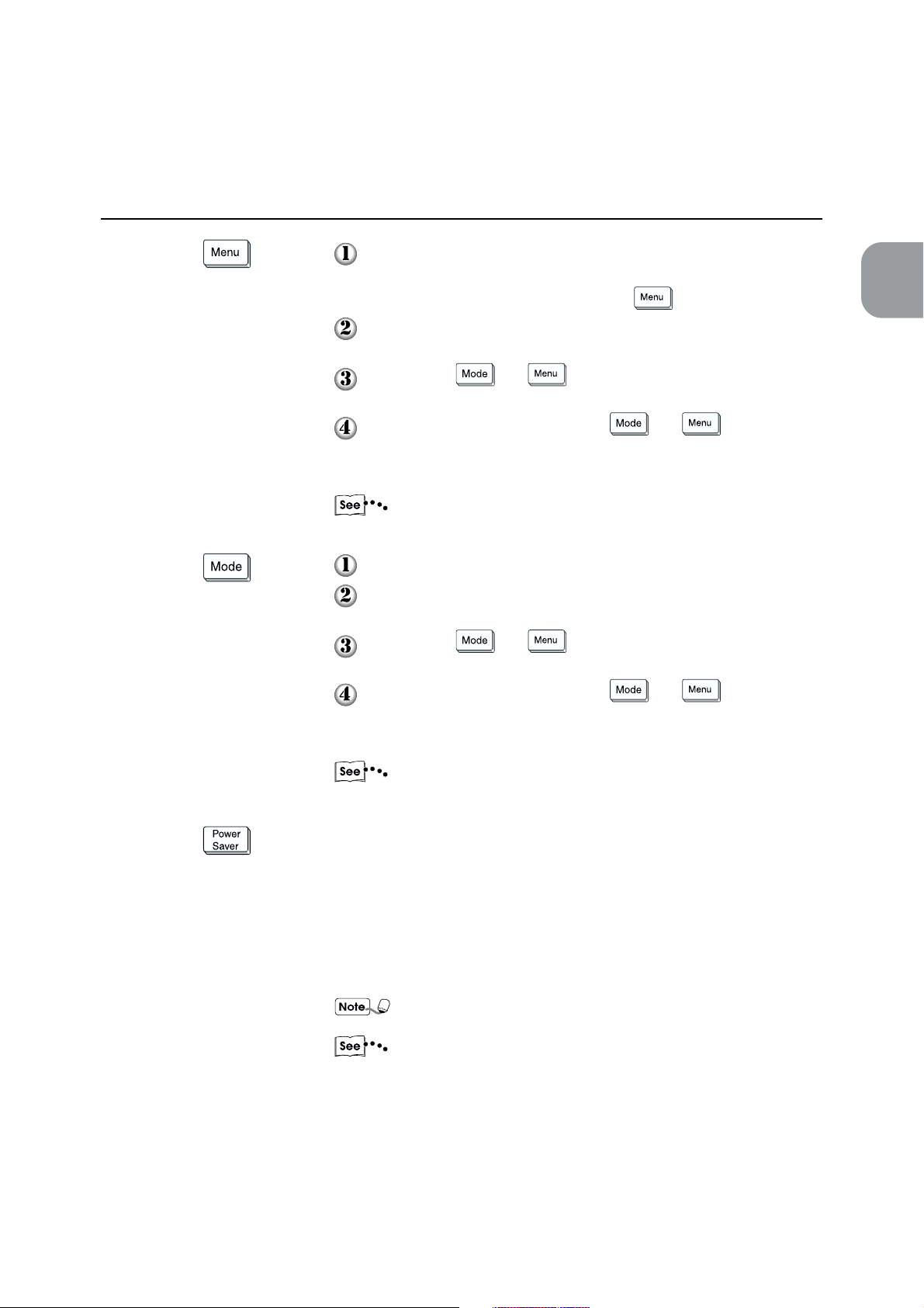
Moves to Common Menu operation.
At this state, the printer will not be able to receive data
automatically. During print procesing,
Returns from the Common Menu to the "Print/Fax Ready" print
screen.
When both and are pressed together, the printing of
jobs in process will be cancelled.
During the pause state, when both and are pressed
together, jobs which have finished receiving data for all interfaces
will be discarded.
"5.3 Common Menu Items" for details on the Common Menu.
Moves to Mode Menu operation.
Returns from the Mode Menu to the "Print/Fax Ready" print
screen.
When both and are pressed together, the printing of
jobs in process will be cancelled.
During the pause state, when both and are pressed
together, jobs which have finished receiving data for all interfaces
will be discarded.
is not accessible.
1
Overview of the Printer
"5.2 Mode Menu Items" for details on the Mode Menu.
Cancels Power Save (Sleep Mode/Off Mode).
Light on
Indicates that Power Save is on. Nothing can be shown in Display.
Light off
Indicates that Power Save is off. Display shows "Please wait" or "Print/
Fax Ready".
After Power Save is off, LED, display and key operations resumes
their functions.
"5.3 Common Menu Items" regarding the setting of lighting
timing of Power Save.
11
Page 24

1.3 Main Components and Their Functions
1.3.3 CD-ROM
1
There are two CD-ROMs included with this manual. One for the printer kit and the other
for the optional PostScript 3 kit. Before installing, read the Readme.txt first.
When you are not able to install from the CD-ROM because of the environment that
you are in, copy the contents onto a floppy disk first before carrying out the
installation.
The files included in the CD-ROMs are as follows:
CD-ROM for the printer kit: “PCL Driver/Network Utility (Windows®)”
• PCL 5e printer driver (for Windows 3.1, Windows 95/98, Windows NT 4.0)
• PCL 6 printer driver (for Windows 3.1, Windows 95/98, Windows NT 4.0)
• NWU (Netware Utility) (for MS-DOS, Windows 3.1, Windows 95/98)
• PD (PrintDirect) (for Windows 95/98)
• DP (Direct Print Utility) (for Windows 95/98)
• SCN (Network Scanner Utility) (for Windows 95/98, Windows NT 4.0)
• DW (DocuWorks patch from 3.0E to 3.02E) (for Windows 95/98, Windows NT 4.0)
• ACROBAT (Adobe Acrobat Reader)
(for Windows 3.1, Windows 95/98, Windows NT 4.0)
• Manual (Printer User Guide, Scanner User Guide, Network Print Environment User
Guide) (in pdf format)
• Readme.txt
CD-ROM for the PostScript 3 kit: “PostScript® Driver Library (Macintosh®/Windows®)”
• AdobePS (Adobe PS printer drivers and PPD files)
(for Windows 95/98, Windows NT 4.0, Macintosh)
• ATM (Adobe Type Manager) (for Windows 95/98, Windows NT 4.0, Macintosh)
• SFONT (Adobe PS 3 Screen Font) (TrueType/Type 1)
(for Windows 95/98, Windows NT 4.0, Macintosh)
• ACROBAT (Adobe Acrobat Reader)
(for Windows 95/98, Windows NT 4.0, Macintosh)
• AdobePS (Adobe PS printer drivers and PPD files)
(for Windows 95/98J, Windows NT 4.0J)
• MS_PS_J (PPD and INF files for Microsoft PostScript)
(for Windows 95J/98J, Windows NT 4.0J)
• Fuji Xerox PS Utility (Macintosh Utility)
• FX Namer (FX Namer Utility)
• Manual (PS Driver User Guide) (in pdf format)
• Readme.txt
All the above files in each of the two CD-ROMs are classified by the OS that they are
meant to be used for.
12
Page 25

1.4 Precautions on Switching
On/Off
·
• After you have turned off the power, wait at least five seconds before turning it on again.
• After the message "Print/Fax Ready" is displayed, wait at least five seconds before turning power off.
1
Besides the above occasions, the printer hard disk may be in use. Note that when you are accessing the
printer hard disk and the power is switched off, the hard disk may not be usable again.
For machine without the fax function, "Print Ready" will be displayed.
Overview of the Printer
13
Page 26

This page is intentionally left blank.
Page 27

Setting Up
2.1 Connecting Cable (Parallel/Serial Interface) ....................................... 16
2.2 Using the Ethernet Interface .................................................................. 20
2.3 Increase/Allocation of Memory.......................................................... 23
Page 28
2.1 Connecting Cable (Parallel/
Serial Interface)
2.1.1 Connecting interface cable
Connect the printer and host device by using parallel interface, serial interface and
Ethernet interface.
CAUTION
When connecting the interface cable, switch off the power supply to prevent possible
electric shock.
The printer can be connected to the parallel interface, serial interface and Ethernet
interface at the same time. Also, print data from all the connected interfaces can be
received.
For the Ethernet interface, an optional interface card is required. See "2.2 Using the
Ethernet Interface" when you want to use the Ethernet interface.
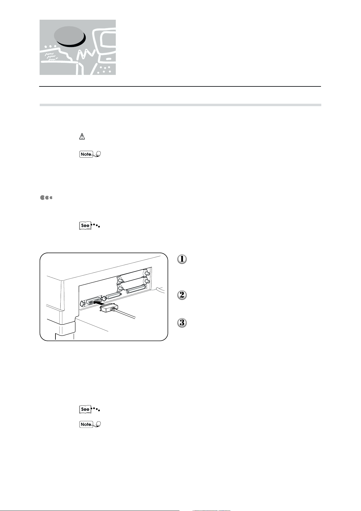
Parallel interface connection
The procedure for connection by parallel interface is explained here.
When connecting to a host device using parallel interface, the optional parallel
interface cable provided by our company is needed. For details, consult the Xerox
Customer Support Centre.
Insert the interface cable connector to the
parallel interface connector and secure it
by the wire clips on both sides.
Connect the other end of the interface
cable connector to the host device.
16
Switch on the printer.
If necessary, set the following items by the printer control panel:
• PDL Mode (Default: PCL 6*)
• PJL Switch (Default: ON)
• Auto Eject Time (Default: 30 sec)
• Bidirectional (Default: ON)
"Chapter 5 Mode Menu/Common Menu" for details on the individual item and the
setting method.
• For normal usage, there is no need to change the default settings of all the items
except Bi-directional.
For Bi-directional, you may need to make changes according to the OS of each
host device. For details, refer to "Chapter 4 Installing/Configuring the Printer
Drivers".
• * If the optional PostScript software kit is installed, factory setting will be Auto.
Page 29
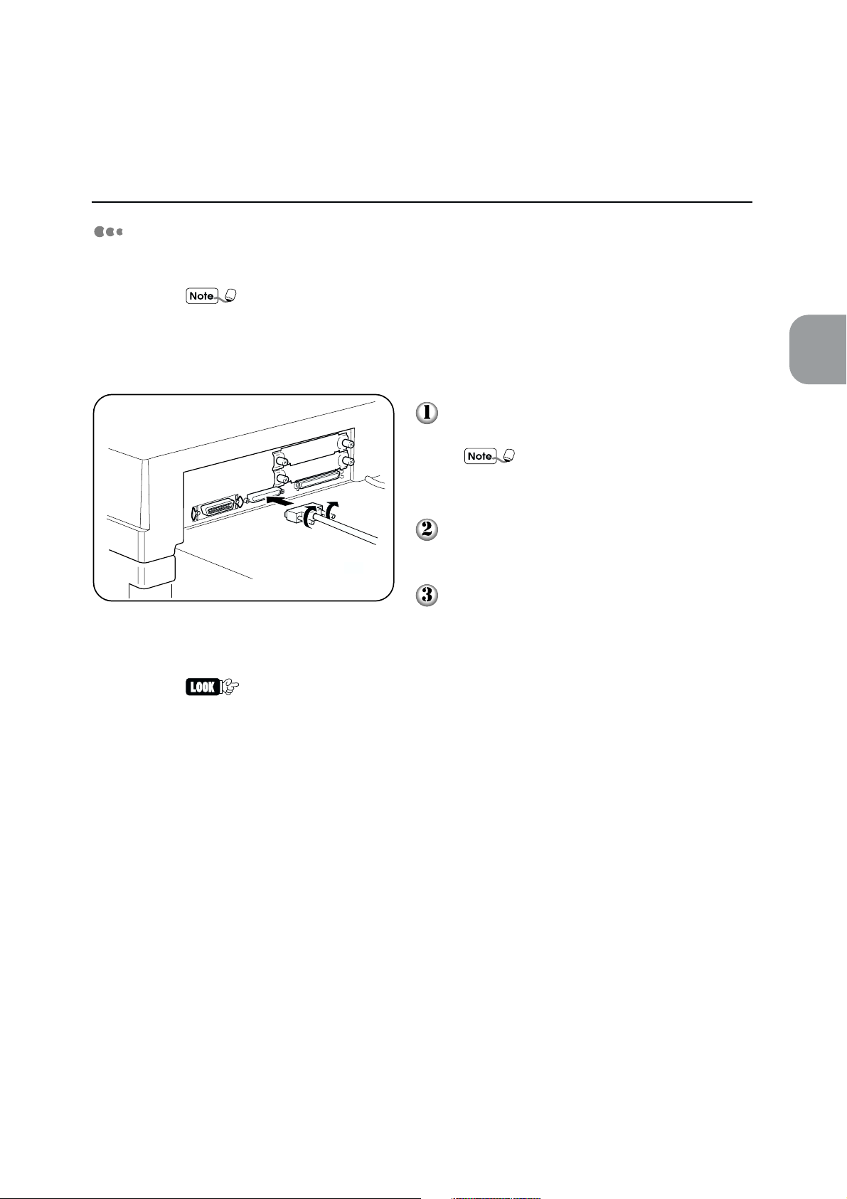
Serial interface connection
The procedure for connection by serial interface is explained here.
• When connecting to a host device using serial interface, a RS-232C cable is
required. This cable is not provided as an option by our company. Refer to
"Appendix B.2 Serial Interface" to prepare the cable (EMI product).
• The serial port is set to inactive when it is shipped out. Change it to active after the
cable is connected.
2.1 Connecting Cable (Parallel/Serial Interface)
2
Setting Up
Insert the interface cable connector to the
serial interface connector and secure it.
For the interface cable, use the
shielded cable (EMI product) made for
your host device.
Connect the other end of the interface cable
connector to the host device.
Switch on the printer.
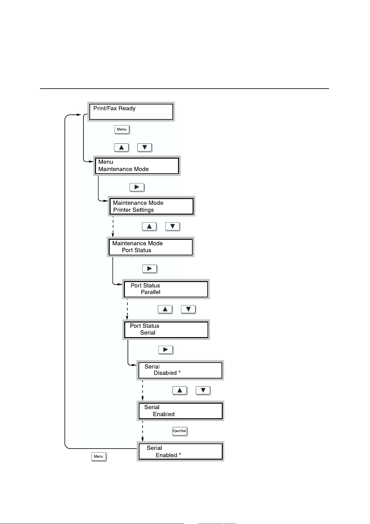
Follow the procedure on the next page to activate the serial port from the printer control
panel:
When messages other than "Ready to Print/Fax" is displayed after Step 10 on the
next page, refer to "7.2 Messages".
17
Page 30
2.1 Connecting Cable (Parallel/Serial Interface)
(1) Press .
(2) Press or a few times.
(3) Press .
(4) Press or a few times.
(When the power is on.)
(Display of Maintenance Mode)
(5) Press .
(6) Press or a few times.
(7) Press .
(8) Press or .
(9) Press .
(Display of port status item)
18
(10) Press
(Returns to the state when power is on. Receiving data possible.)
.
(Serial port activated)
Page 31

2.1 Connecting Cable (Parallel/Serial Interface)
Similarly, check the values of the host device for the following items and change the
settings when they are different from the printer default values:
• Baud Rate (default: 9600)
• Data Length (default: 8 bit)
• Stop Bit (default: 1 bit)
• Parity (default: None)
• Xon-Xoff Control (default: Yes)
• DTR Control (default: Fix-High)
If necessary, set the value for the following items. However, there is no need to change
the default setting for these items for normal usage.
• PDL Mode (default: PCL 6*)
• PJL Switch (default: ON)
• Auto Eject Time (default: 30 sec)
• Serial memory** (default: 64 KB)
2
Setting Up
"Chapter 5 Mode Menu/Common Menu" for details on the setting items of the printer.
• * If the optional PostScript software kit is installed, factory setting will be Auto.
• ** Maintenance Mode>Memory Change>ReceiveBufferMem>Serial
19
Page 32

2.2 Using the Ethernet Interface
If you want to use the Ethernet interface, you need to install the optional interface card (100Base-TX,
10Base-T or 10Base-5) first. This section explains the procedure for installing the Ethernet interface card
and for connecting by the Ethernet interface.
2.2.1 Installing the Ethernet interface card
Check that the display window indicates "Ready". Turn the power off and then unplug the
power cord.
CAUTION
Make sure the power is switched off and the machine unplugged before you begin the
installation. Otherwise, there is a danger of electric shock.
The printing data left inside the printer or the printer memory will be erased when
the power is off.
Remove the two screws from the slot for the
expansion interface card and then take away
the shield cover.
Keep the removed screws and shield
cover.
Insert the interface card into either the left
or right slot and fix it with the two screws.
Make sure the card is inserted right in
so that it touches the connector at the
end of the slot.
20
Page 33

2.2.2 Connecting the Ethernet interface
Connecting by the Ethernet interface will enable the following environments to be used:
• 100Base-TX
• 10Base-T
• 10Base-5
100Base-TX and 10Base-T are set to switch automatically. When using 10Base-5
environment, be sure to set the Ethernet values from the printer control panel after
connecting the cable.
The procedure for connection by Ethernet interface is as follows:
2.2 Using the Ethernet Interface
2
Setting Up
Connect the interface cable to the Ethernet
interface connector.
Do not connect the interface cable to
the two Ethernet interface connectors
together as this will cause poor
transmission or breakdown.
For the interface cable, use the cable
suited to the network.
Switch on the power of the printer.
When connecting connector for 10Base-5, follow the procedure on the next page and set
the value of Ethernet setting to 10Base-5. When connecting TX/T connector, also refer to
the procedure on next page and change the setting if you would like to fix the transmission
speed for 100Base-TX or 10Base-T.
After setting Ethernet, change the setting from the printer or host device, depending on the
environment setting that you are in.
The Network Print Environment User Guide for the setting method.
21
Page 34

2.2 Using the Ethernet Interface
(1) Press .
(When the power is on)
(2) Press
(3) Press .
or a few times.
(4) Press
(5) Press .
(6) Press or a few times.
or a few times.
(Display of Maintenance Mode)
(Display of Ethernet setting)
22
(7) Press .
(Setting Ethernet to 10Base-5)
(8) Press .
(Returns to the state when power is on. Receiving data possible.)
Page 35

2.3 Increase/Allocation of
Memory
This sections explains how to allocate memory when increasing it.
2.3.1 Uses
Memory is meant for the following uses:
• System
• Receive buffer
• Page buffer
• PCL 6 memory
• PS memory
2.3.2 Suggested values
2
Setting Up
System
Area used by the printer system, with the capacity remaining unchangeable.
Receive buffer
A receive buffer is prepared for each port to receive data from multiple ports. There are
various types of receive buffer:
• Parallel memory
• Serial memory
• lpd spool
• NetWare memory
• AppleTalk memory
Parallel memory
This is a receive buffer for parallel interface use. In general, the default values are
sufficient but if necessary, increase the capacity. When the capacity is increased, the
processing might become faster. When the parallel interface is not in use, inactivate it and
allocate the memory for other purposes.
Serial memory
This is a receive buffer for serial interface use. In general, the default values are sufficient
but if necessary, increase the capacity. When the capacity is increased, the processing
might become faster. When the serial interface is not in use, inactivate it and allocate the
memory for other purposes.
23
Page 36

2.3 Increase/Allocation of Memory
lpd spool
Area for lpd, FX PrintDirect and Direct Print Utility spool use. When the hard disk is
connected, it is possible to select the spool point from the memory and hard disk, as well as
to stop spooling. Even when the spooling is stopped, the receive buffer is needed.
When you want to ensure that the area for spooling use is more than 32 MB, it is
recommended that the hard disk be connected.
NetWare memory
Receive buffer for NetWare use. In general, the default values are sufficient but if
necessary, increase the capacity.
AppleTalk memory
Receive buffer for AppleTalk use. It is recommended that you maintain many areas of this
memory if possible.
Page buffer
Area for drawing the actual print image. It is possible to allocate this area from the
remaining area after all the other uses have been allocated. To confirm the page buffer
capacity, print the printer settings list and then check the actual page buffer. If the page
buffer is too small, it will affect the performance and duplex printing may be rejected.
If you are using the PostScript language, refer to “E.2 Precautions and Limitations”.
PCL 6 memory
Area for the use of PCL 6. This memory is to store the interim data for creating the print
image. By increasing the memory capacity, the printing speed may be increased.
PS memory
Area for use by the PostScript software. By increasing the memory capacity, printing
speed may be increased.
24
Page 37

Useful Operations
3.1 Flow of Printing/Fax Transmission ...................................................... 26
3.2 Cancelling Printing/Fax Transmission.................................................. 28
3.3 Outputting ............................................................................................. 31
3.4 Main Frame Control Panel Operations During Printing/Transmission .....
............................................................................................................. 33
3.5 Removing Documents Output to the Stacker Tray................................. 34
3.6 Outputting Lists/Reports ....................................................................... 35
3.7 Printer Functions .................................................................................. 37
Page 38

3.1 Flow of Printing/Fax
3.1.1 For Windows
The basic flow of printing/fax transmission from Windows environment is as follows:
(This may differ depending on the host device and system configuration used.)
Activate application software used by the
host device
Refer to the manual of the application regarding its operation.
If necessary
Transmission
Operate menu
Before sending print/fax data from the host device, check the
following:
(1)Port status in Common Menu > Maintenance Mode > Port Status
(2)Print mode of the port in Common Menu > Port Setting > PDL Mode
"5.3 Common Menu Items"
Specify printing/faxing from application,
etc.
Refer to the manual of the application regarding its operation.
"4.4 Printing/Faxing" for details on faxing.
If necessary
Stop printing/faxing
"3.2 Cancelling Printing/Fax Transmission"
If necessary
Output
26
"3.3 Outputting"
End
Page 39

3.1.2 For DOS (printing only)
The basic flow when printing from the DOS environment is as follows:
(This may differ depending on the host device and system configuration used.)
Activate application software to be used
by the host device
Refer to the manual of the application regarding its operation.
If necessary
Operate menu
3.1 Flow of Printing/Fax Transmission
3
Before sending print/fax data from the host device, check the
following:
(1)Port status in Common Menu > Maintenance Mode > Port Status
(2)Print mode of the port in Common Menu > Port Setting > PDL
Mode
(3)Printing method (e.g. scale) by the PDL Mode
Specify printing from application etc.
Refer to the manual of the application regarding its operation.
If necessary
Stop printing
Useful Operations
"5.3 Common Menu Items"
"5.2 Mode Menu Items"
"3.2 Cancelling Printing/Fax Transmission"
End
If necessary
Output
"3.3 Outputting"
27
Page 40

3.2 Cancelling Printing/Fax
Transmission
This section explains about the cancellation of printing/fax transmission.
To cancel printing/fax transmission, first of all cancel instructions from the host device.
After cancelling from the host device, carry out one of the following operations:
• Cancelling jobs in process (see 3.2.2)
• Cancelling all jobs in the printer (see 3.2.3)
• Cancelling fax transmission from touch panel display (see 3.2.4)
3.2.1 Cancelling from host device
The procedure to cancel printing instructions from the host device is explained here.
Refer to the following based on the type of OS that you are using:
Windows® 95/Windows® 98
Cancelling from Windows® 95/Windows® 98:
Windows® 3.1
Cancelling from Windows® 3.1:
Display the "Printers" window.
(Start > Settings > Printers)
Double-click the appropriate printer icon.
In the displayed window, click the appropriate
document name and from the “Document”
menu, select Cancel Printing.
Double-click Printer Manager from the
"Main" window.
In the displayed window, click the appropriate
document name and from the “Document”
menu, select Delete Document.
28
Page 41

Windows NT® 4.0
Cancelling from Windows NT® 4.0:
3.2.2 Cancelling jobs in process
To cancel jobs in process from the printer, press and of the the printer control
panel together. However, the page which is being printed will still be printed and output.
3.2.3 Cancelling all jobs in the printer
3.2 Cancelling Printing/Fax Transmission
Display the "Printers" window.
(Start > Settings > Printers)
Double-click the appropriate printer icon.
In the displayed window, click the appropriate
document name and from the “Document”
menu, select Cancel.
3
Useful Operations
To cancel printing all jobs received by the printer.
This operation can stop the receiving of data and empty the buffer.
• All data will be erased when this operation is executed.
• Buffer is the storing location of data sent from the host device.
There is also a way to execute all the jobs in the printer and print them out.
See "3.3.2 Outputting all jobs in the printer" for details on the printing method.
The operation procedure is as follows:
When the display is at a state as shown on the
left, press
The machine assumes pause mode.
.
When is pressed, the printer
will automatically be unable to
receive data.
29
Page 42

3.2 Cancelling Printing/Fax Transmission
Press and together.
The cancellation of printing will be processed.
When the processing is complete, "Pause" will
be shown.
Press .
"Print/Fax Ready" will be shown.
3.2.4 Cancelling fax transmission from touch panel display
Jobs that are being faxed and fax transmission jobs that have been arranged are
cancelled by using the touch panel display. See the User Guide (Facsimile) for details on
the cancellation method.
30
Page 43

3.3 Outputting
This section explains the two types of outputting:
• Forced outputting of remaining print data (see 3.3.1)
• Outputting all jobs in the printer (see 3.3.2)
3.3.1 Forced outputting of remaining print data
For the PCL 6 emulation mode, data will not be output until a full page of data is collected.
If the last piece of data ends at the middle of a page, it will wait for the next data until the
present Auto Eject Time has passed and "Data wait" will be shown on the display.
The operation of forcibly printing data in the printer without waiting for the Auto Eject
Time to pass in such instance is known as forced outputing.
The procedure is as follows:
For parallel and serial interfaces, the next job sent when the display shows "Data
wait" might not be printed properly.
Send the next job after forced outputting or when Auto Eject Time is over.
"5.3 Common Menu Items" regarding Auto Eject Time.
3
Useful Operations
When the display is at the state as shown on
the left, press
Printing will commence.
When printing is done, "Print/Fax Ready"
will be shown.
.
31
Page 44

3.3 Outputting
3.3.2 Outputting all jobs in the printer
To execute and print all jobs received in the printer.
This operation can stop the receiving of data and empty the buffer.
The procedure is as follows:
There is also a way to erase all jobs in the printer. Refer to "3.2.3 Cancelling all jobs
in the printer" regarding the way to erase.
When the display is at the state as shown on
the left, press
.
The Pause mode is activated.
When is pressed, the printer will
automatically be unable to receive data.
Press .
The printing starts.
When all the jobs have been executed and
printed, "Pause" will be shown.
For parallel and serial interfaces, data might be received in the midst of a job
depending on the timing when
In this case, all data following this will be recognised as a new job after
pressed and then processed as a new job after the pause state is released in Step
is pressed in Step .
Press .
"Print/Fax Ready" will be shown.
is
.
32
After the pause state is released here, data that have been treated as a new job will
not be printed properly if the PDL Mode is set to AUTO.
"5.3 Common Menu Items" regarding the PDL Mode setting.
Page 45

3.4 Main Frame Control Panel
Operations During Printing/
Transmission
This section explains about the method of operating the main frame control panel during printing/
transmission. The touch panel display during printing will be as follows:
• When Close is selected on the screen below, the start arrangement of the next copy/fax operations can
be carried out without cancelling any printer operations. Also, you can press Job Status > Stop,
choose "Printer" job, press Stop to stop and then carry out the copy/fax operation. The job that has
been stopped will be automatically resumed.
• Print jobs cannot be stopped by the Main Frame Control Panel.
Printer
Close
Printing in progress...
The main frame control panel operations during printing/transmission are as follows:
Main frame control panel operations Printer actions
Pressing Interrupt during printing. When Interrupt is pressed, the printing will be stopped
temporarily and the copy/fax functions can be used. When
Interrupt is pressed again, the interrupt mode will be disabled
and printing will resume.
Pressing Job Status > Stop, select job and Stop. Printing will be temporarily stopped and the copy/fax
functions can be used. The interrupted printing will be
resumed automatically. Fax transmission will be stopped.
3
Useful Operations
33
Page 46

3.5 Removing Documents
Output to the Stacker Tray
When removing documents output to the Stacker Tray, be sure to press the Pause/Restart button of the
Staple Finisher to stop the Finisher operations temporarily.
The procedure is as follows:
Press Pause/Restart.
Check that the Stacker Tray has lowered all
the trays completely before removing the
documents output to the stacker tray.
During printing of documents that are
to be stapled, when Pause/Restart or
of the main body is pressed, the
stacker tray will be lowered once the
documents that are being printed are
output.
Press Pause/Restart again.
The Staple Finisher will resume operation.
The temporarily stopped state will be
cancelled automatically about 60
seconds later and printing will resume.
34
Page 47

3.6 Outputting Lists/Reports
This section explains about the types of lists/reports and how to print them.
3.6.1 Types of lists/reports
Besides printing data sent from the host device, this machine is equipped with
several other printing functions, known as Print Utility.
The Print Utility of this machine are as follows:
• PCL 6 Settings
• Printer Settings
• Error History
• Print History
• Job Template Server Settings
• PCL 6 Font List
• PS Font List (available when the optional software kit is installed)
3
Useful Operations
Print Utility is executed at a resolution of 400 dpi.
"Appendix C Print Utility" for details on the contents of Print Utility.
3.6.2 Printing lists/reports
The procedure to print the Print Utility items is shown on the next page:
35
Page 48

3.6 Outputting Lists/Reports
(1) Press .
(When the printer is on)
(2) Press
(3) Press .
or a few times.
(Display of Print Utility)
(4) If you are printing "PCL 6 Settings", press . If not, press
or until you reach the desired item and then press .
(The example here shows the printing
of "PCL 6 Settings".)
(5) Press
(6) The "PCL 6 Settings" will be printed and
.
output and then the following screen displayed:
36
(7) To print other items, press
the "Print Utility/PCL 6 Settings" display. Or press
to return to the print screen.
to return to Step (4) and
Page 49

3.7 Printer Functions
This section explains about the relations between the printing function and the copying/faxing functions.
Auto Tray Switch
When printing is done by auto paper supply, the Auto Tray Switch feature will usually be
activated. This feature is independent of the copying/faxing function setting.
Paper Tray Priority
For the printing function, the trays are allocated priority as follows: Tray 1, Tray 2,
Tray 3 and then Tray 4 (Tray 1 has the highest priority). This feature is independent
of the copying/faxing function setting.
When the High-Capacity Feeder is installed, the allocated priority is: Hi-Cap. Feeder 1,
Hi-Cap. Feeder 2, Tray 1 and Tray 2.
3
Useful Operations
Printing Priority
Printing will be prioritised according to the setting made from the main frame control
panel. The priority can be chosen from the following: Printer Document, Fax Receive
Document, Auto-Output Report.
User Guide (Facsimile) for the setting method.
Copy/fax functions and their relation with printer function
Operating the main frame control panel
• No printing can be done when operating the main frame control panel. However,
printing instructions can be received from the host device.
• When a certain time* has passed after operating the main frame control panel,
documents specified from the host device will be printed.
Transmitting
Document with printing instruction specified from the host device will be printed according
to the order received.
Copying
Outputting received document
• Printing cannot be done during copying and outputting received document. However,
printing instructions can be received from the host device.
• After all the documents of copying and outputting received document are ejected,
documents with printing instructions from the host device will be printed.
37
Page 50

3.7 Printer Functions
Interrupting
Printing cannot be done during the interrupt mode. However, printing instructions can be
received from the host device.
Press Interrupt to end the interrupt mode and printing will be processed. Even during the
interrupt mode, the printing process will resume if no operations are carried out after a
certain time.
* : This time setting is done from the main frame control panel. See the User Guide (Facsimile) for
the setting method.
38
Page 51

Installing/
Configuring the
Printer Drivers
4.1 About the Printer Drivers.................................................................... 40
4.2 Installing/Uninstalling the Printer Drivers............................................ 41
4.3 Configuring the Printer Drivers .......................................................... 46
4.4 Printing/Faxing ..................................................................................... 73
Page 52

4
4.1 About the Printer Drivers
This section gives an overview of the printer drivers.
4.1.1 The PCL 5e/PCL 6 printer drivers
The PCL 5e/PCL 6 printer drivers are installed on the Windows operating systems to
provide a standard interface between an application program and the Xerox DC 400/
350/250 printer device. By installing these printer drivers, print jobs can be converted into
the PJL and PCL 5e/PCL 6 printer languages and then print through the printer device.
These drivers are also equipped with the direct fax feature which sends fax directly from
your PC through the printer.
These printer drivers are system specific, each will only run on either Windows 3.1/95/98
or Windows NT 4.0. There are altogether six printer drivers included:
• PCL 5e printer driver for Windows 3.1
• PCL 5e printer driver for Windows 95/98
• PCL 5e printer driver for Windows NT 4.0
• PCL 6 printer driver for Windows 3.1
• PCL 6 printer driver for Windows 95/98
• PCL 6 printer driver for Windows NT 4.0
4.1.2 Installation/configuration methods
The methods of installing/configuring the PCL 5e and PCL 6 printer drivers as well as the
procedures for printing/faxing using these drivers are basically the same. Regardless of the
operating system (OS) you are in, the basic steps are similar except for the look of some
of the graphics. Therefore, only one printer driver will be used to discuss these operations
in this chapter but any differences among the PCL 5e and PCL 6 printer drivers will be
pointed out.
4.1.3 Settings on the Xerox DC 400/350/250 printer
Make sure the PJL switch for the interface is turned to ON. If the PJL switch is turned to
OFF, the following functions will be disabled:
• JOB/EOJ-Job separator
• Fax function
• Collate
• Job offset
• Staple function
• Resolution
• Image enhancement
• Economode
• PCL XL emulation
40
Page 53

4.2 Installing/Uninstalling the
Printer Drivers
This section describes the procedure for installing and uninstalling the printer drivers.
Two methods of installation are described here, one for a local network printer and the other for a network
printer. If you have installed an earlier version of the printer driver, uninstall it first by following the
procedure in 4.2.3 before installing the new version.
4.2.1 For a local Xerox DC 400/350/250 printer
Local printer refers to a printer that is directly connected to your computer.
Procedure
Start Windows 95, Windows 98, Windows NT 4.0 or Windows 3.1.
In this example, we will install the PCL 6 printer driver on the Windows 95 OS.
From the "Start" menu, select Run. The "Run" dialog box appears.
For the Windows 3.1 OS, select Run from the "File" menu of the "Program
Manager" dialog box.
Insert in the "PCL Driver/Network Utility (Windows®)" CD-ROM and enter
"E:\English\DC400\Win95_98\PCL6\Setup\Setup.exe". Click OK.
In this example, we will use drive E as the CD-ROM drive.
The "Printer Installation" dialog box appears. Select Port and ensure that "Make
this the Default Printer" check box is selected. Click Next. At the next "Printer
Installation" dialog box displayed, click Next too.
4
Installing/Configuring the Printer Drivers
41
Page 54

4
4.2 Installing/Uninstalling the Printer Drivers
The "End User Licence Agreement" dialog box appears. Read through the licence
agreement carefully. If you have no objections to it, click on the checkbox for "I
accept the terms of the above Licence Agreement" and then click Next.
The "Ready to Start Copying" dialog box appears. Click Finish to start the
installation.
42
After the installation is completed, a dialog box as shown below appears.
Click Restart Windows Now, Exit to Windows or Printer Setup as needed.
"4.3 Configuring the Printer Drivers" on how to configure the printer driver.
• Restart Windows for the effect to take place.
• You may run the "Setup.exe" program to install the Windows 95/98 printer
driver as an alternate driver on the Windows NT server (workstation) after
you have installed the printer driver for Windows NT 4.0. In this case, as
there is no need to restart Windows, click Exit to Windows. When down-
loading the alternate Windows 95/98 driver installed in Windows NT on the
Windows 95/98 client computer, use the "Add Printer Wizard" dialog box.
Page 55

4.2 Installing/Uninstalling the Printer Drivers
4.2.2 For a network Xerox DC 400/350/250 printer
Network printer refers to printer that is connected to your computer through a network.
Procedure
Follow Steps to of "4.2.1 For a local Xerox DC 400/350/250 printer" to
display the "Printer Installation" dialog box.
In this example, we will install the PCL 6 printer driver on the Windows 95 OS.
Click Add Network Port. The "Add Network Printer Port" dialog box
appears. Select the network printer from "Network Neighborhood".
If you do not know the network address of the network printer, consult your
system administrator.
4
Installing/Configuring the Printer Drivers
Click OK. The "Printer Installation" dialog box showing the network path of the
network printer appears.
Follow Steps to of "4.2.1 For a local Xerox DC 400/350/250 printer" to
complete the installation procedure.
43
Page 56

4
4.2 Installing/Uninstalling the Printer Drivers
4.2.3 Uninstalling the printer drivers
In this example, we will uninstall the PCL 6 printer driver on the Windows 95 OS.
• For drivers installed by the "Setup.exe" program, use the "Unsetup.exe" program
to uninstall.
• For Windows 95/Windows 98 alternate drivers installed in Windows NT server
(workstation), use the "Unsetup.exe" program to uninstall the Windows 95/
Windows 98 drivers and then activate the "Unsetup.exe" program of the Windows
NT driver.
• To uninstall the alternate drivers downloaded using the "Add Printer Wizard"
dialog box at the client computer, open the "Printers" window and erase the
applicable printer icons.
Procedure
From the "Start" menu, select Run. In the "Run" dialog box displayed, click
Browse.
For the Windows 3.1 OS, select Run from the "File" menu of the "Program
Manager" dialog box.
Insert in the "PCL Driver/Network Utility" CD-ROM and select the CD-ROM
drive in the "Browse" dialog box. Next, double-click Win95_98, PCL6, Setup and
then select Unsetup.exe. Click Open to close the "Browse" dialog box.
• For the Windows 3.1 OS, click OK to close the "Browse" dialog box.
• When uninstalling any PCL 5e/PCL 6 driver, remember to use the
"Unsetup.exe" program of the correct driver and of the same version as the
"Setup.exe" program used for installation.
The path for the unsetup program appears in the "Run" dialog box. Click OK to
continue.
The "Printer Uninstall" dialog box appears with a drop-down menu for you to select
the printer name to delete. Select the printer that you want to delete and click
Next.
44
Page 57

4.2 Installing/Uninstalling the Printer Drivers
If you are uninstalling a driver from the Windows NT 4.0 OS, the following left
dialog box will be displayed instead and clicking Next will display the following
right dialox box with the "Model" name. Click Next to continue.
A "Ready to Start Deleting" dialog box appears.
4
Installing/Configuring the Printer Drivers
Click Finish to start the uninstalling process. When the process is completed, click
Restart Windows Now to ensure that the driver is completely removed from the
system.
45
Page 58

4.3 Configuring the Printer
Drivers
This section describes how to configure the printer driver from the printer properties dialog box. This
dialog box will appear if you click Printer Setup on the "Installation Sucessful" screen. If, however, you
have quit the printer setup program and are trying to re-access the dialog box, follow the procedure in
"4.3.1 Accessing the printer properties dialog box" to display the dialog box first.
This dialog box includes multiple tabs such as "Printer" and "Paper/Output" to set up printing conditions.
First, you need to set appropriate options on the "Printer" tab before configuring on the other tabs.
Otherwise, the other tabs may not show options appropriate to your machine.
For Windows NT 4.0 drivers: You have to define settings on both the "Printer" and "Fonts" tabs (for the
PCL 5e driver) or just on the "Printer" tab (for the PCL 6 driver) from this "Properties" dialog box before
accessing the "Default" dialog box to define the other properties.
For details of all the different properties, refer to "4.3.2 Setting the printer properties".
4
4.3.1 Accessing the printer properties dialog box
For Windows 95/Windows 98
Click the Start menu, select Settings and then Printers. The "Printers" window
appears.
In this example, we will use the PCL 6 driver for the Windows 95 OS.
Click the appropriate Xerox DC 400/350/250 printer icon.
Select Properties from the "File" menu to display the following "Properties" dialog
box.
46
Page 59

For Windows 3.1
In the "Program Manager" dialog box, double-click Main, followed by Control
Panel, and then Printers. The "Printers" window appears.
Ensure that you have selected the appropriate Xerox DC 400/350/250 printer icon
in Installed Printers, and then click Setup to display the following setup dialog
box.
4.3 Configuring the Printer Drivers
In this example, we will use the PCL 6 driver.
4
Installing/Configuring the Printer Drivers
47
Page 60

4
4.3 Configuring the Printer Drivers
For Windows NT 4.0
Accessing the printer properties dialog box
Follow the procedure for Windows 95/Windows 98 to display the following
"Properties" dialog box.
For the PCL 5e driver: To define settings on the "Printer" and "Fonts" tabs.
For the PCL 6 driver: To define settings on the "Printer" tab.
In this example, we will use the PCL 5e driver.
Accessing the document defaults dialog box
Follow Step 1 and Step 2 of the procedure for Windows 95/Windows 98 to select
the Xerox DC 400/350/250 printer icon.
Select Document Defaults from the "File" menu to display the following "Default"
dialog box to define settings on the other tabs.
48
Page 61

4.3.2 Setting the printer properties
Through the printer properties (and document default) dialog box, the printer driver will
provide an interface for you to ensure that the driver settings match those of the physical
printer and to select printer option settings for the different properties. The settings made
here will be the default printer configuration for printing the subsequent job. Although an
application may change the page setup each time a job is printed, it will not affect these
default settings. Changes to these configurations can only be made through these dialog
boxes. Not all properties are, however, available for the six different drivers. The following
table lists out the properties available for each driver as well as the items of each property
not commonly available to all the drivers:
PCL 5e PCL 6
Property Win 3.1 Win 95/98 Win NT 4.0 Win 3.1 Win 95/98 Win NT 4.0
Printer
4.3 Configuring the Printer Drivers
4
* Device Halftoning ×× ××
* Error Report ×××
Paper/Output
Output Options
* CentreWare Supports × ×
* EMF Spooling ×× ××
Graphics
* Grey Scale ×××
* Halftoning ×××
* Halftone Color Adjustment ×× ××
Overlays
* Download Now ×××
Fonts ×××
Layout ×××
Watermarks ×××
Fax Option
Advanced ×× ××
Installing/Configuring the Printer Drivers
: available; ×: not available
*: items of the property that may/may not be available to the driver
49
Page 62

4.3 Configuring the Printer Drivers
Before listing out the different properties, here is a summary of them:
• Printer
The settings here is used to configure the printer hardware options. Optional device items
that are physically installed on the printer must be indicated here to the driver that they are
available for use e.g. Duplex Unit, Offset Catch Device etc.
• Paper/Output
This property controls several aspects of how the the printer works with paper and how it
handles a print job. Settings include Job Type (i.e. Print or Fax), Paper Size, Paper Source,
Image Orientation, Copies, Output Destination, etc.
• Output Options
Includes settings on how the printed output is to be processed by the printer options, such
as collation if hard disk has been installed on printer, Job Offset if OCT is available on
printer etc.
4
• Graphics
Settings contained here controls the quality of printed output as well as how the Graphics
and TrueType fonts will be processed and printed.
• Overlays
Allows you to create, use and delete page overlays for the printer.
• Fonts (for PCL 5e drivers only)
Use this to install soft (disk-based) fonts and scalable typefaces on the printer.
• Layout (for PCL 6 drivers only)
The layout property provides a few "job finishing" features to modify the printed layout of
a document like N-Up printing, Booklet Printing, Fit to Page, Scaling, Logical On Physical.
• Watermarks (for PCL 6 drivers only)
A Watermark is a light image printed in the background on a page. The PCL 6 driver
allows text (as watermark) to be printed in the background or foreground and placed
across the first page or all pages of a document. This property dialog allows you to create,
delete and modify such watermarks.
• Fax Option
Allows you to specify fax attributes like fax resolution and whether to generate
transmission report or to include a header for faxing.
Unlike the properties of the other tabs, the description of the properties of this tab is in
"4.4.2 Faxing from an application".
50
• Advanced (for Windows NT 4.0 drivers only)
Displays a hierarchical list of control items that relate to document property. It presents a
summary of the document default settings of the driver and allows user to change setting
of each item by selecting them here.
Page 63

Printer
4.3 Configuring the Printer Drivers
The "Printer" tab defines the current hardware configuration of the printer. The optional
devices that are physically installed on the printer must be indicated here that they are
available for use.
4
Installing/Configuring the Printer Drivers
The "Sharing" tab appears when the print sharing feature is turned on in the
"Network" dialog box which is accessed by double-clicking the "Network" icon in
the Control Panel.
Paper Source Options
Specify the optional paper source that is attached to your printer besides the default paper
source device, Tray 1. The printer image and the Paper Source drop-down list in the
"Paper/Output" tab will change accordingly once this is updated.
Bypass Tray
Select this if your printer is installed with this manual feeder which is able to handle
various paper sizes.
If this is not checked, Bypass Tray (Manual) will not be available for Paper
Source on the "Paper/Output" tab.
Select Tray Body:
Provides two options of which either and only one must be installed in the printer:
• 3-Tray Cabinet (default)
Select this if your printer is installed with this input tray cabinet which allows
paper to be fed from three trays (Tray 2, Tray 3, Tray 4).
• High Capacity Feeder
Select this if your printer is installed with this input tray cabinet which allows
paper to be fed from one tray (Tray 2) and two high capacity feeders (Hi-Cap.
Feeder 1, Hi-Cap Feeder 2).
• If 3-Tray Cabinet is not checked, Tray 3 and Tray 4 will not be available for
Paper Source on the "Paper/Output" tab.
• If High Capacity Feeder is not checked, Hi-Cap. Feeder 1 and Hi-Cap.
Feeder 2 will not be available for Paper Source on the "Paper/Output" tab.
51
Page 64

4
4.3 Configuring the Printer Drivers
Paper Output Options
Specify the optional output tray that can be attached to your printer for additional capacity
over the standard output tray.
Side Output Tray
Select this if your printer is installed with this face-up tray.
Staple Finisher
Select this if your printer is installed with this attachment of three finisher trays
(Stacker Tray 1- Stacker Tray 3). It is equipped with the Offset Catch Device and
the stapler. Cannot be installed together with the Mail Box.
Mail Box
Select this if your printer is installed with this attachment of 10 output bins. Cannot
be installed together with the Staple Finisher.
• If Side Output Tray is not checked, Side Output Tray will not be available for
Paper Output on the "Paper/Output" tab.
• If Staple Finisher is not checked, Stacker-Auto and Stacker Tray 1 - Stacker
Tray 3 will not be available for Paper Output on the "Paper/Output" tab.
• If Mail Box is not checked, Mail Box Bin 1 - Mail Box Bin 10 will not be
available for Paper Output on the "Paper/Output" tab.
Offset Catch Device
Select this if your printer is installed with the job offset device which supports both "Offset
Per Job" and "Offset Per Set" functions. Only the standard Centre Tray and the stacker
trays can be equipped with the job offset device. Default is off.
If this is not checked, the job offset settings will not be available for Job Offset on
the "Output Options" tab.
Duplex Unit (Inverter)
Select this if your printer is installed with a duplex unit to perform 2-sided printing. Default
is off.
If this is not checked, the duplex printing options on the "Paper/Output" tab will
not be available.
Hard Disk
Select this if your printer is installed with a hard disk which enables the printer to support
job collation. Default is off.
If this is not checked, Collate and the staple positions on the "Output Options" tab
will not be available.
Fax Unit
Select this if your printer is installed with a fax unit to send a fax job. Default is off.
If this is not checked, Fax will not be available for Job Type on the "Paper/Output"
tab.
ISDN/G4 Kit
Select this if your fax module has a G4 kit which allows ISDN communication. Enabled
only if Fax Unit is selected. Default is off.
If this is not checked, G4-Auto will not be available for Communication Mode on
the "Comm. Setting" dialog box which is displayed when Comm. Settings on the
"Fax Recipient" dialog box is pressed.
52
Page 65

4.3 Configuring the Printer Drivers
Paper Detected by Tray
Select one of the following two paper sizes which are mutual exclusively detected by the
printer:
• B4 (257 × 364 mm) (default)
• Legal (8.5 × 14")
The selected paper size will be available for selection under Paper Size on the "Paper/
Output" tab while the unselected one will not be available.
If you want to change the paper detection from B4 (257×364 mm) to Legal (8.5×14") or
vice versa, please contact the Xerox Customer Support Centre.
Make sure that the "Paper Detected by Tray" setting is consistent with thep hysical
cabinet tray setting. Otherwise, trouble with printing may arise.
4
Installing/Configuring the Printer Drivers
Windows NT 4.0
Error Report (for PCL 6 drivers only)
Specify whether or not errors are to be reported when printing a PCL 6 job. Options
include:
• No Reporting
The printer will not generate any error report.
• Error Page (default)
Error page will be printed when the printer encounters error in printing the job.
Device Halftoning (for Windows NT 4.0 drivers only)
Click this button to display the "Device Color/Halftone Properties" dialog box to define the
colour and halftone properties for the printing device.
53
Page 66

4
4.3 Configuring the Printer Drivers
Paper/Output
The "Paper/Output" tab has option settings that determine the print environment in which a
job is printed. Notice that there are image displays of Job Type, Paper Size, Image
Orientation and Duplex Print to the left of these drop-down lists, which will change
according to the selections made. There is also a display of the printer with clickable image
areas of the paper input and output devices. You can either click on these displays or
choose from the combo boxes to make selections.
Job Type
Specify the type of job you are handling:
• Print
• Fax (available only if Fax Unit is selected on the "Printer" tab.)
Copies
Specify the number of copies to print. The valid range is 1-999 copies. Default is 1.
Paper Size
Specify the paper size to use for the print data. Options include:
• A4 (210 × 297 mm) (default)
• 8.5 × 11" (Letter)
• B5 (182 × 257 mm)
• B4 (257 × 364 mm)
when Fax is selected for Job Type on the "Printer" tab: available at all times;
(
when Print is selected: available in either one of the following conditions:
(a) B4 (257 × 364 mm) is selected for Paper Detected by Tray on "Printer" tab; or
(b) 8.5 × 14" (Legal) for Paper Detected by Tray and Bypass Tray for Paper
Source Options are selected on the "Printer" tab)
54
Page 67

4.3 Configuring the Printer Drivers
• 8.5 × 13" (Folio)
• 8.5 × 14" (Legal)
when Fax is selected for Job Type on the "Printer" tab: available at all times;
(
when Print is selected: available in either one of the following conditions:
(a) 8.5 × 14" (Legal) is selected for Paper Detected by Tray on "Printer" tab; or
(b) B4 (257 × 364 mm) for Paper Detected by Tray and Bypass Tray for Paper
Source Options are selected on the "Printer" tab)
• 8K (267 × 388 mm)
• A3 (297 × 420 mm)
• 11 × 17" (Ledger)
• A5 (148 × 210 mm)
• Postcard (100 × 148 mm)
when Fax is selected for Job Type on the "Printer" tab: available at all times;
(
when Print is selected: available when Bypass Tray is selected for Paper Source
Options on the "Printer" tab)
• Booklet on A4 (
(available only when Print for Job Type and Duplex Unit (Inverter) are selected on
the "Printer" tab)
• Booklet on Letter (
(available at the same conditions as Booklet on A4)
• Booklet on A3 (
(available at the same conditions as Booklet on A4)
• Booklet on Ledger (
(available at the same conditions as Booklet on A4)
• Custom Paper Size
A user defined size ranging from 100 × 148 mm (min.) to 297 × 431 mm (max.).
(when Fax is selected for Job Type on "Printer" tab: available at all times;
when Print is selected: available when Bypass Tray is selected for Paper Source
Options on the "Printer" tab)
for PCL 6 drivers only)
for PCL 6 drivers only)
for PCL 6 drivers only)
for PCL 6 drivers only)
4
Installing/Configuring the Printer Drivers
Paper Source
Specify the tray to use. Options include:
• Auto Tray (default)
Paper will be automatically selected.
• Tray 1 - Tray 4
Paper will be fed from the specified trays. Tray 3 and Tray 4 are available only if
3-Tray Cabinet is selected for Paper Source Options on the "Printer" tab.
• Hi-Cap. Feeder 1 - Hi-Cap. Feeder 2
Paper will be fed from the specified high capacity feeder. Available only if High
Capacity Feeder is selected for Paper Source Options on the "Printer" tab.
• Bypass Tray (Manual)
Paper will be fed from the bypass tray. Available only if Bypass Tray is selected for
Paper Source Options on the "Printer" tab.
55
Page 68

4
4.3 Configuring the Printer Drivers
The paper sizes available for each paper source are as follows:
Paper Size Auto Tray/Tray 1 Tray 2-Tray 4 HCF 1-HCF 2 Bypass Tray
8.5 × 11" (Letter)
A4
B5
B4 ×
8.5 × 13" (Folio) ×
8.5 × 14" (Legal) ×
8K ×
A3 ×
11 × 17" (Ledger) ×
A5 ××
Booklet on A4* ×
Booklet on Letter* ×
Booklet on A3* ××
Booklet on Ledger* ××
Postcard ×××
Custom ×××
• : supported; ×: not supported; HCF: High Capacity Feeder
• *
For PCL 6 drivers only: not available for any of the paper source if Fit to Page or
Logical On Physical is selected for Layout Mode on the "Layout" tab.
Paper Output
Specify an output destination. Options include:
• Centre Tray (default)
Printouts are sent to the centre tray with the printed side facing down.
• Side Output Tray
Printouts are sent to the side output tray with the printed side facing up. Available
only if Side Output Tray is selected for Paper Output Options on the "Printer" tab.
• Mail Box Bin 1 - Mail Box Bin 10
Printouts are sent to the specified bin(s) with the printed side facing down. Useful for
preventing a mixed up of documents sent by different users. Available only if Mail
Box is selected for Paper Output Options on the "Printer" tab.
• Stacker-Auto
Printouts are sent to a stacker tray automatically selected by the printer with the
printed side facing down. Available only if Staple Finisher is selected for Paper
Output Options on the "Printer" tab.
• Stacker Tray 1- Stacker Tray 3
Printouts are sent to the specified stacker tray with the printed side facing down.
Available only if Staple Finisher is selected for Paper Output Options on the
"Printer" tab.
56
Page 69

4.3 Configuring the Printer Drivers
Image Orientation
Specify the orientation of the image when printed.
• Portrait (default)
Portrait means the page is taller than it is wide when you view the printed page.
• Landscape
Landscape means the page is wider than it is tall when you view the printed page.
Duplex Print
Specify whether you want to print on one or both sides of the paper.
Duplex printing means to print on both sides of the paper. If you are printing on both sides,
you have to decide on the binding position too. Options include:
• Duplex Off (default)
Prints only on one page.
• Long Edge Binding
Two-sided printing aligned to the long edge of the paper.
• Short Edge Binding
Two-sided printing aligned to the short edge of the paper.
All duplex printing options (except Duplex Off) are available only if Duplex Unit
(Inverter) is selected on the "Printer" tab.
4
Installing/Configuring the Printer Drivers
Custom Paper Size
Click this button to display the "Custom Paper Size" dialog box to define the non-standard
size of the print media that you are using. For a print job, it is enabled only if Bypass Tray
is selected for Paper Source Options on the "Printer" tab.
Items include:
Width
Enter the width of range 100 - 297 mm / 3.94 - 11.69 inch with an increment of 0.1
mm / 0.01 inch.
Length
Enter the length of range 148 - 432 mm / 5.83 - 17.0 inch with an increment of 0.1
mm / 0.01 inch.
Unit
Select the unit of measurement used to set the length and width.
57
Page 70

4.3 Configuring the Printer Drivers
Output Options
4
Windows 95/98 Windows NT 4.0
The "Output Options" tab has some advanced features for sending a print job. Notice that
there are image displays of Collate Settings, Staple Position Settings and Use Document
Monitor which will change according to the selections made.You can either click on these
displays or choose from the drop-down lists to make selections.
Job Offset Settings
This feature provides a means of identifying one print job from others in the printer output
tray by outputting jobs in an in-out manner.
Job Offset
Options include:
• None (default)
No job offset i.e. to turn off the printer offset mechanism.
• Offset Per Job
Apply printer offset mechanism for each print job.
• Offset Per Set
Apply printer offset mechanism at the beginning of each set (or copy) of job.
This option is meant for printing two or more copies of a print job. When this
option is selected for printing only one copy of a job, it has the same output
effect as Offset Per Job.
If Collate is selected for Collate Settings, each set printed will be output to
the Centre Tray or any of the stacker tray in an in-out manner. If Collate is
not selected, the printouts will be arranged by their page number in an in-out
manner.
All job offsets (except None) are available in either one of the following conditions:
(a) Offset Catch Device is selected on the "Printer" tab and Centre Tray is selected
for Paper Output on the "Paper/Output" tab; or
(b) Staple Finisher is selected on the "Printer" tab and either Stacker-Auto or one
of the three stacker trays is selected for Paper Output on the "Paper/Output" tab.
58
Page 71

4.3 Configuring the Printer Drivers
Collate Settings
Specify how you want your document to be arranged.
Collate
Click on the check box to collate or uncollate your documents. Enabled only if all of
the following conditions are met:
(1) Hard Disk is selected on the "Printer" tab; &
(2) more than one copy is selected for Copies on the "Paper/Output" tab.
Default is on.
Staple Position Settings
Specify where to staple your printed document. Paper sizes that can be stapled include A5,
B5, A4, 8.5 × 11", B4, A3, 8.5 × 13", 8.5 × 14", 8K and 11 × 17".
Staple Position
Options include:
• None (default)
Staple function off.
• Top Left Corner
Apply one staple at the top-left corner of paper.
• Top Double
Apply two staples at the top edge of paper.
• Top Right Corner
Apply one staple at the top-right corner of paper.
• Left Double
Apply two staples at the left edge of paper.
• Right Double
Apply two staples at the right edge of paper.
• Bottom Left Corner
Apply one staple at the bottom-left corner of paper.
• Bottom Double
Apply two staples at the bottom edge of paper.
• Bottom Right Corner
Apply one staple at the bottom-right corner of paper.
All staple positions (except None) are available only if all of the following conditions
are met:
(1) Staple Finisher is selected for Paper Output Options on the "Printer" tab;
(2) Hard Disk is selected on the "Printer" tab;
(3) Stacker-Auto or one of the three stacker trays is selected for Paper Output on
the "Paper/Output" tab; &
(4) 1 is selected for Copies on the "Paper/Output" tab or more than 1 copy is selected
for Copies and Collate is selected for Collate Settings.
4
Installing/Configuring the Printer Drivers
The Staple Finisher can staple up to a maximum of 50 sheets.
59
Page 72

4
4.3 Configuring the Printer Drivers
First Sheet
Enables you to select for the first sheet of your document, a paper source different from
the rest of the output sheets as selected in Paper Source on the "Paper/Output" tab. Note
that the paper size used for this different paper source must be the same as the document.
Different Paper Source
This check box must be selected before the drop-down list of paper source options is
enabled. Disabled in any one of the following conditions:
(a) Postcard or Custom Paper Size is selected for Paper Size on the "Paper/Output"
tab;
(b) N-Ups is selected for Layout Mode on the "Layout" tab and more than 1-Up is
selected for Pages Per Sheet (
(c) Booklet Printing is selected for Layout Mode on the "Layout" tab (
drivers only).
Default is off.
The options available for the different paper source are identical to the settings of Paper
Source on the "Paper/Output" tab. Default is Auto Tray.
CentreWare Supports (for all except Windows 3.1 drivers)
The Document Monitor tool must be installed on the computer in order for the following
check boxes to be enabled:
Use Document Monitor
The Document Monitor is a CentreWare software tool that enables network users to
monitor and track the status of documents (print/fax jobs) being processed by the
Xerox Document Centre System. Enabled if CentreWare is installed. Default is off.
Enable Raster/EMF Spooled Jobs (
A raster print job or an EMF spooled job on Windows NT 4.0 system may not be
successfully monitored by the Document Monitor. This option allows users to
specify Raster and/or EMF settings. Enabled if Use Document Monitor is selected.
Default is off.
for PCL 6 drivers only); or
for PCL 6
for Windows NT 4.0 drivers only)
60
Metafile (EMF) Spooling (for Windows NT 4.0 drivers only)
Specifies the format in which to store printing information on your disk while a job is
waiting to be printed. Turning this control on will enable the EMF disk file format.
Otherwise, RAW format will be used. Enabled in either one of the following conditions:
(a) Vector is selected for Graphics Mode on the "Graphics" tab; or
(b) Enable Raster/EMF Spooled Jobs is selected for CentreWare Supports.
Page 73

Graphics
4.3 Configuring the Printer Drivers
4
The "Graphics" tab has option settings that affect the quality of a printed output. Notice
that there is a visual representation of the selected graphics mode and printer resolution.
Clicking the images will toggle both the radio button/drop-down list setting and the image
display between the Raster and Vector selections/400 dpi and 600 dpi selections.
Graphics Mode
The graphics mode option enables you to optimise graphics printing, increasing speed and
quality. Options include:
• Raster
All graphics are sent to the printer as bitmap raster images (i.e. images composed of
individual dots). Under this option, the printed output may appear to be a closer
match to the screen image than the other mode, but printing is slower.
• Vector (default)
This mode enables images to be printed faster but not all graphic images can be
printed under this mode. If the printed graphic images do not appear the same way
as they did on your screen, select Raster and reprint your graphic. Note that
however, this is not a What-You-See-Is-What-You-Get representation.
Grey Scale (for PCL 5e drivers only)
Enables you to adjust the grey scale colour for different print jobs. Options include:
• Photographic Images (default)
This option works best for colour images as it produces a soft contrast between
various shades of grey.
• Line Art
This option produces solid lines and sharp contrasts between shaded areas, and is
usually used for images with intricate lines.
• Scanned Images
This option produces exceptional quality and clarity for images originally scanned in
through a scanner.
Installing/Configuring the Printer Drivers
61
Page 74

4
4.3 Configuring the Printer Drivers
Halftoning (for PCL 6 drivers only)
Halftone refers to a type of pattern that is applied to the printed image. By using a
combination of black dots, these patterns produce a grey appearance on the printed image.
This Halftoning feature is designed to process images (e.g. photographs) but not the
computer generated art (e.g. clip art). The appearance of the printed image will be differed
by the Halftone settings.
Note the different settings available for the different PCL 6 drivers.
For Windows 3.1 and Windows 95/98 PCL 6 drivers:
• Device (default)
Image objects will be rendered by default halftoning attributes.
• Line Art
Provides solid lines and sharp contrasts between shaded areas and it is used for
images with intricate lines.
• Fine
Provides smooth shades of grey.
• Coarse
Provides rough greyscale with high contrasts for images that will be scanned/copied.
• Diffusion
Creates the appearance of grey scales by randomly placing individual dots of ink. Best
for photographic images but requires more processing time. Available only if Raster
is selected for Graphics Mode.
For the Windows NT 4.0 PCL 6 driver:
• Device (default)
Image objects will be rendered by default halftoning attributes. Available only if
Vector is selected for Graphics Mode.
• System
Enables the System Halftoning. Click Halftone Colour Adjustment for system
halftone colour adjustmnent.
62
Image Enhancement
Enhances the quality of the output image. Default is on.
All Texts to Black
Prints all coloured text (except white) in black. If this is not specified, colours will be
printed in varying degree of greys. Default is off.
EconoMode
Used to reduce the amount of toner the printer uses by using less toner on each page.
When EconoMode is on, text and graphics are printed in grey rather than black. It is
suitable for printing of drafts. Default is off.
Printer Resolution
Specify the resolution for printing at either 400 dpi or 600 dpi. A higher resolution usually
produces a better quality output but it takes a longer time to print. Default is 600 dpi.
Page 75

4.3 Configuring the Printer Drivers
TrueType Mode
The drivers are capable to download the Windows TrueType fonts in three different ways:
• Download as True Type (default)
Prints text by downloading the complete character set of TrueType fonts in an outline
form that the printer can deal with directly. Downloaded fonts are vector-based,
scalable typefaces.
• Download as Bit Image
Prints text by downloading each TrueType character as an individual bitmap font.
Downloaded fonts are raster-based, non-scalable typefaces.
• Print as Graphics
Prints text as graphic images. The printed output may appear to be a closer match to
the screen image than the other options, though it may print slower. Enabled only if
Raster is selected for Graphics Mode.
Use Printer TrueType fonts
When this is on, the printer prints by using the printer-resident fonts instead of by
downloading fonts to the printer, unless the required fonts are not present in the
printer. This will speed up the printing process and give the printer its best
performance. Default is on. Disabled if Print as Graphics is selected for True Type
Mode.
4
Installing/Configuring the Printer Drivers
Halftone Colour Adjustment (for Windows NT 4.0 drivers only)
Click this button to display the "Halftone Color Adjustment" dialog box for setting the
colour adjustment values that are used to adjust the colour of bitmap images for printing.
Colour adjustments affect certain attributes of the image, such as contrast and brightness.
For the Windows NT 4.0 PCL 6 driver: enabled only if System is selected for Halftoning.
The "Negative" check box in the "Halftone Color Adjustment" dialog box specifies
whether or not the colours of bitmap images are inverted. Inverting colours
produces a negative image of the bitmap.
Windows NT 4.0
63
Page 76

4
4.3 Configuring the Printer Drivers
Overlays
The "Overlays" tab allows you to create, use and delete page overlays for your printer. A
Page Overlay is a group of PCL commands and/or data created, downloaded and stored in
the printer by you. Once stored in the printer, a page overlay can be invoked upon request
and eliminates the need to download the same information over again, thus saving
transmission time. For example, if you want to print a company letterhead on every letter
that you are sending, you have to first create a page overlay for this letterhead and store it
in the printer. Then, whenever you want to print letters with this letterhead, simply send a
page overlay command to the printer to print.
Load Overlay
When you want to use file from an external source as an overlay, click this button to
inform the overlay manager of the file and its location.
If you source an external file from a floppy disk and then remove the disk from
the disk drive, the file will no longer be available as an overlay. If you intend to use
this file regularly, it is recommended that you copy the file to your system local disk
before using this button.
Create Overlay
Creates and stores a Page Overlay from a file containing the overlay that you want.
You have to first open the file with the overlay that you want, then, select the "Print"
command from the "File" menu. When the "Print" dialog appears, select the Xerox
DC 400/350/250 printer and click Properties. Then, select the "Overlays" tab in the
printer properties dialog box. Click Create Overlay, and enter a name for the
overlay in the "File name" box. You may select another pathname other than the
default pathname (C:\pageover). Click OK when you have finished. When a
confirmation dialog box appears, click Yes to confirm the operation. This will store
the overlay in your computer disk. If you click No, this operation will be aborted.
64
Page 77

4.3 Configuring the Printer Drivers
Delete Overlay
To delete an overlay, select it in the "Overlay" list box, and click Delete Overlay. Click
Yes to confirm deletion and No to abort the action.
Download Now (for PCL 5e drivers only)
Allows you to permanently download overlays to the printer. Using overlays that are
already resident on the printer may improve printing performance. You can download
overlays to memory.
Delete All
Deletes all overlays from any or all of the destinations.
Query Page Overlay
When this is selected, a message box requesting for confirmation will appear whenever a
page overlay command is sent to the printer. If this option is off, the selected page overlay
file will be sent directly to the printer.
This option is not active if No Overlay is selected or if the currently selected overlay
has been permanently downloaded to the printer.
Selected Overlay status
Displays information on the selected overlay.
Overlay Creation status
Displays information regarding the creation of overlays.
Fonts (for PCL 5e drivers only)
4
Installing/Configuring the Printer Drivers
Windows 95/98 Windows NT 4.0
This tab dialog allows you to install fonts to your printer.
For PCL 6 drivers: a Font Installer is included for managing PCL fonts, which will be
(
enabled when the driver is invoked through the Windows Control Panel.)
65
Page 78

4
4.3 Configuring the Printer Drivers
For Windows 3.1 and Windows 95/98 drivers:
Add Fonts
Click to install new fonts to your printer. A window appears for you to specify the source
location of the fonts. Enter the location. When a list of fonts appears in the list box on the
right, select the font that you want to install and click Add. Follow the on-screen
instruction to complete the operation.
Copy Fonts to New Port
If you are using more than one Xerox DC 400/350/250 printers, or if you change the port
which your printer is connected to, you can move or copy your installed fonts to the other
printer on that port by clicking this button.
Print Font Listing
Prints a list of available printer fonts.
Move
Moves the selected fonts to the specified destination (i.e. printer or port).
Copy
Copies the selected fonts to the specified destination (i.e. printer or port).
Delete
If you are no longer using a font, you can delete it from your Windows applications or/and
your hard disk.
Edit
If you have purchased a disk-based font which has the same name as a font you are
already using, you should change the name of either font by clicking this button after you
have selected that font.
• Permanent
Downloading a font permanently ensures a font stays in your printer memory until the
printer is turned off. This is especially useful for a frequently used font. You can generally
print faster when you install fonts as permanent but it can also limit the amount of printer
memory available for printing graphics and complex page.
• Temporary
If you install a font as temporary, the font is loaded into your printer memory only when
you want to print a document with that font. This works well, for instance, when you
rarely use a font, when you need your printer memory for printing graphics, when you are
using a variety of fonts in one document, or when you are printing to a shared printer.
For the Windows NT 4.0 driver:
<<
Downloads one or more available fonts.
66
>>
Deletes a font from the list of downloaded fonts.
Font Summary
Prints the list of currently downloaded fonts.
Page 79

Layout (for PCL 6 drivers only)
The Layout property provides five job finishing features for you to modify the printed
layout of a document. Notice that an image is displayed for each type of layout mode
selected and which also indicates the current page orientation.
4.3 Configuring the Printer Drivers
4
Installing/Configuring the Printer Drivers
Layout Mode
Provides a list of the options of job finishing features:
• N-Ups (default)
• Booklet Printing
• Fit To Page
• Scaling
• Logical On Physical
Selecting each of the features will display one of the following corresponding options:
N-Up Printing (available when N-Ups is selected for Layout Mode)
The N-Up function allows more than one document page to be
printed on a same physical page by dividing the physical page into
N smaller physical pages. Each document page is then reduced
and translated to fit into the new smaller physical page. In this
way, multiple pages are printed onto a single physical page.
Pages Per Sheet
Lists the possible N pages per sheet for the N-Up printing function: 1, 2, 4, 6, 9, 16.
Default is 1.
67
Page 80

4
4.3 Configuring the Printer Drivers
Page Border
To provide options of printing each document page with a page border on the
physical page:
• None (default)
No page border is drawn.
• Grid
A rectangle is drawn to divide each document page.
• Shadow
A rectangle with drop shadow effect is drawn around each document page.
Enabled when more than 1-Up is selected for Pages Per Sheet.
No Rotation on Same Sheet
Specify how N-Up document pages of different orientation are to be handled on the
same physical page by comparing other document pages with the first document
page. When this is not selected, document pages with different orientation from the
first document page will be rotated to match its orientation, with minimum size
reduction. When this is selected, document pages with different orientation from the
first document page will not be rotated but will be scaled down in order to fit into the
same physical page. Enabled when more than 1-Up is selected for Pages Per Sheet.
Default is off.
Booklet Printing (available when Booklet Printing is selected for Layout Mode)
This function allows the document to be printed as a booklet. It
ensures that the document pages will be re-ordered and printed
2-Up and that the output sheets when folded and stacked will
have the correct page order.
When this feature is chosen in Layout Mode, the following dialog box will be displayed.
Click OK to proceed. There are two types of booklet printing:
• Scale To Booklet (default)
Document pages will be scaled down and printed 2-Up on each side of the paper with
the paper size of the document. Unlike Use Booklet Paper Size, this option allows
you to do a simple booklet printing without having to know the booklet paper size to
use in order to prevent the document being truncated when printed as a booklet.
• Use Booklet Paper Size
Document pages will be printed 2-Up without scaling on the specified target paper
size. Selecting any one of the booklet paper size here will change the current paper
size setting in the driver to the booklet size automatically.
68
Page 81

4.3 Configuring the Printer Drivers
The options available for the the different booklet paper size are:
• Booklet on Letter (default)
• Booklet on Ledger
• Booklet on A4
• Booklet on A3
Available only when Use Booklet Paper Size is selected.
Fit To Page (available when Fit To Page is selected for Layout Mode)
This function allows document to be printed on a specified paper
size that is different from the original page size of the document
by scaling the document page to fit onto the specified page size.
Fit to Paper Size
Lists the possible paper sizes that can be used. The options available for the paper size
are similar to the settings of Paper Size on the "Paper/Output" tab. The "Fit to Page"
function can output to all paper sizes. Default is A4 (210 × 297 mm).
Scaling (available when Scaling is selected for Layout Mode)
4
Installing/Configuring the Printer Drivers
This function allows enlargement or reduction of each document
page to be printed.
Scale Factor (%)
Define a scale factor of between 50 to 400 % for enlargement (>100 %) or reduction
(<100 %) of your page. Default is 100 %.
Page Position
Specify the position where the document page is to be printed on the output:
• Top Left
• Top Right
• Center (default)
• Bottom Left
• Bottom Right
Logical On Physical (available when Logical On Physical is selected for Layout
Mode)
This function allows you to print on a paper size that is different
from the page size designated for your document without scaling
the page image. It is intended to print a document onto a bigger
paper size than its original size. When the paper size is smaller,
the printout may not be of the expected result.
69
Page 82

4
4.3 Configuring the Printer Drivers
Target Paper Size
Lists the possible paper sizes that can be used. The options available for the paper size
are similar to the settings of Paper Size on the "Paper/Output" tab. Default is A4
(210 × 297 mm).
Page Position
Specify the position where the document page is to be printed on the output:
• Top Left
• Top Right
• Center (default)
• Bottom Left
• Bottom Right
Page Border
To provide options of printing each document page with a page border on the
physical page:
• None (default)
No page border is drawn.
• Shadow
A rectangle with drop shadow effect is drawn around each document page.
Watermarks (for PCL 6 drivers only)
This property dialog allows you to create, edit and delete watermarks, which are light
images printed in the background on a page.
70
Page 83

The procedure to create a watermark is as follows:
Specify the text for the watermark in Text (maximum 100 characters).
Select Fonts to display the "Font" dialog box and specify the font, font style and
size. Font style includes regular, italic, bold and bold italic; size ranges from 6-
900.
Select Color to display the "Color" dialog box and specify/create the required
colour.
Specify the position and angle of the text by adjusting the "Angle" scrollbar (-90 to
+90 degrees) and the scrollbar just below the preview window* which moves the
x and y position values. These position values are in the 1/100ths (0.01) of an inch
and are offsets from the page centre. To reset the position to the paper origin,
press Center Watermark.
Click Add to add the new watermark to the "Watermark" list.
4.3 Configuring the Printer Drivers
The procedure to edit a watermark is as follows:
Select an existing watermark from the "Watermark" drop-down list.
Make changes to it as required.
Click Update to replace the previous version or Add to save a modified version of
the watermark.
The procedure to delete a watermark is as follows:
Select an existing watermark from the "Watermark" drop-down list.
Click Delete to remove the watermark from the list.
To print a watermark, the options available include:
In Background
Selecting this prints the watermark underneath the primary texts and graphics in the
document; otherwise the watermark will be printed on top of all images in the document. Disabled if As Outline Only is selected.
On First Page Only
Selecting this prints watermark on the first page of the document only; otherwise the
watermark will be printed on all pages.
As Outline Only
Selecting this prints the text outline of the watermark which is always printed on top
of all document images. Disabled if In Background is selected.
4
Installing/Configuring the Printer Drivers
71
Page 84

4.3 Configuring the Printer Drivers
Advanced (for Windows NT 4.0 drivers only)
4
The NT drivers will display a hierarchical list of control items that relate to document
property. It presents a summary of the document default settings of the driver and allows
user to change setting of each item by selecting them here. A control corresponding to the
selected item will be available for user input. The settings include only items from the
"Paper/Output", "Output Options" and "Graphic" tabs.
72
Page 85

4.4 Printing/Faxing
This section describes the procedures to send print and fax jobs from an application.
4.4.1 Printing from an application
Procedure
From the "File" menu of the application, select Print.
In the "Print" dialog box displayed ("Print Setup" for Windows 3.1), check that
the printer used is the Xerox DC 400/350/250 printer. If not, select it from the
printer name drop-down list.
Click Properties (Options for Windows 3.1) to display the properties dialog
box.
Make the necessary changes to the different properties (see "4.3 Configuring the
Printer Drivers"). Note that the changes made to these settings will be the default
printer configuration for printing the subsequent jobs of the application.
To make settings for the present job without changing the default settings, change
the page setup by using the relevant menu options from the "File" menu (e.g.
Document setup).
Close the properties dialog box.
Click OK in the "Print" dialog box to start printing.
This Xerox DC 400/350/250 printer allows you to print the PostScript language
by using the PostScript 3 Kit. For details, see "Appendix E PostScript 3 Kit".
4.4.2 Faxing from an application
To be able to fax from your Xerox DC 400/350/250 printer, you must attach a fax
unit to it and then on the "Printer" tab, select Fax Unit. The driver will then enable the
properties for faxing (Fax Recipient and Fax Option) and disable option settings that are
not applicable to it e.g. only options like Image Orientation and Paper Size on the
"Paper/Output" tab are enabled for fax job selection.
Follow the procedure below to send a fax job but refer to the sections following it, Fax
Recipient and Fax Option for details on the different options available.
4
Installing/Configuring the Printer Drivers
Procedure
From the "File" menu of the application, select Print.
In the "Print" dialog box displayed ("Print Setup" for Windows 3.1), check that the
printer used is the Xerox DC 400/350/250 printer. If not, select it from the printer
name drop-down list.
73
Page 86

4
4.4 Printing/Faxing
Click Properties (Options for Windows 3.1) to display the properties dialog box.
Select Fax for Job Type on the "Paper/Output" tab.
Make the necessary specification in the various properties tabs available and then
click OK to close the properties dialog box and to display the "Print" dialog box.
Click OK. The "Fax Recipient" dialog box appears.
Input the information for Name and Fax Number, and then click Add to List. Or
if you have previously saved the list of recipients, select it from Recipient List to
display the recipients' information. You can also access the list of recipients from
files other than the one specified in the "Recipient List" box, by clicking Open File.
Click OK to send the fax. The "Fax Job Confirmation" dialog box appears.
74
Click OK to confirm sending the fax job or Abort to cancel it. You may also select
Delay Send to specify the time for the fax job to be sent later.
Page 87

Fax Recipient
Recipients are the individuals or groups to whom the fax is to be sent. The Xerox DC 400/
350/250 printer is capable of sending a fax job to a group of recipients of no more than 50.
The "Fax Recipient" dialog box enables you to specify the information of a fax recipient
and to define a list of recipients who will receive the same fax job.
Name
Enter the name of the individual or the relay station to which you are sending the fax. The
characters used should not exceed 30 characters. Valid characters include ASCII printable
code from 20H (space) to 7AH ('z'). The reserved codes of the driver are '{', '}' and '|'.
Fax Number
Enter the fax number of the individual or the relay station to which you are sending the
fax. A fax number can contain up to 30 characters including letters, numbers, '-' and
characters for DTMF command. Entry of characters '[', ']', '{', '}', '|', ',' and spaces are
not permitted.
When dialing the fax number, the letter will be translated into a number as follows:
ABCè2, DEFè3, GHIè4, JKLè5, MNOè6, PQRSè7, TUVè8, WXYZè9.
4.4 Printing/Faxing
4
Installing/Configuring the Printer Drivers
Recipient's fax number must be specified before the fax job from an application can
be sent.
Add to List
To send a fax, you have to enter the fax number and optional name in the respective fields,
and then click Add To List. The fax address is only confirmed when it is entered in the
list. You can add a maximum of 50 recipients to the list.
If you did not click Add To List after entering the name and fax number, the
recipient's particular will not be valid.
Remove From List
Removes the selected entry in Recipient List.
Recipient List File
Displays the path of the current recipient list file.
If the recipient list file is created by an older version driver, the following dialog box will be
displayed when you try to open it with this new driver that you are using:
If you click No, the file will not be converted and the previous dialog box will be active
again. If you click Yes, a "Save Conversion As" dialog box will be displayed. Specify a
new file name with extension ".afd" and then click OK. A new recipient list file will be
created with this new name and the previous file will remain as it is.
Note that recipient list file created by the following versions of the different printer drivers
(or later versions) cannot be opened by any earlier version of the drivers:
75
Page 88

4.4 Printing/Faxing
• version 1.0.2b of PCL 5e drivers for Window 3.1x, Windows 95/98, Windows NT 4.0;
• version 1.0.5b of PCL 6 drivers for Window 3.1x, Windows 95/98;
• version 1.0.1 of PCL 6 driver for Windows NT 4.0.
The following dialog box will be displayed if you try to do so:
If you cannot read the recipient list file with the driver that you are using now, obtain a
later version of the driver than the one mentioned above.
New File
Click this to open a new file to store recipient data.
4
Open File
Click this to open an existing file that contains recipient data.
Save File As
Click this to copy the current recipient list file in another name.
Recipient List
You may select any of the recipient lists from the drop-down list. To create a recipient list,
enter the name and fax number of the recipients whom you want to include in a list in the
"Recipient List" box, and click Save List As.
Recipient Info
Select a recipient in the list box, then click this button. A dialog box displaying information
of the selected recipient appears. You may enter or edit information regarding this recipient,
such as his name, company, fax number, voice number, and e-mail address here.
Comm. Settings
Click this to specify the communication settings of the selected recipient in the displayed
"Comm. Setting" dialog box.
Communication Mode
Select a communication protocol for sending the fax job from the drop-down list.
The options are: G3-Auto, G3-Overseas and G4-Auto.
(G4-Auto is available only if ISDN/G4 Kit is selected on the "Printer" tab.)
Secure Send
Secure Send mode sends a fax job to a particular mailbox at the receiving end. When
this is selected, the following options will be available. For security purpose, you may
assign a password to access the designated mailbox using the "Password" control.
Mailbox ID: Enter the mailbox ID of the mailbox at the receiving end
(1-200).
Password: Assign a 4-digit password for a fax job under Secure Send
mode.
76
Page 89

4.4 Printing/Faxing
When Secure Send is selected When Relay Send is selected
Relay Send
Relay Send mode sends a fax job to a particular relay station, and from there, the fax
job are distributed to the various receiving destinations. You may send to a maximum
of 20 destinations via a relay station. By turning this mode on, you are setting up the
selected recipient as a relay station. When this is selected, the following options will
be available.
Relay Station ID: Enter the ID of the relay station to which you are sending a
relay fax job (1-99).
Print at Relay Station:Select this option to print the fax job at the relay station.
Group Sending: Select this option if you are entering a group sent ID in
Destination ID below.
Destination ID: Enter the destination ID of the recipient who is going to
receive a relay fax job via the specified relay station. After
specifying the recipient's destination ID, press Add To to
add it to Destination List. The default destination ID is 199 but when Group Sending is selected, it becomes 1-9.
Destination List: It shows the confirmed destinations that will receive the
relay fax job. You may specify up to 20 destinations here.
A group ID is prefixed with a "#".
Add To: This button is used to transfer the specified destination ID
from Destination ID to Destination List.
Remove: This button is used to remove the selected destination ID
from Destination List.
4
Installing/Configuring the Printer Drivers
Save List As
Click this button to copy the current recipient list in another name. The "Save Recipient
List" dialog box appears and you can enter a recipient list name of up to 30 characters in
List Name to identify the list.
Delete List
To delete a recipient list, select the list from the Recipient List and then click Delete List.
A dialog box requesting for confirmation appears.
77
Page 90

4
4.4 Printing/Faxing
Fax Option
The "Fax Option" tab enables you to specify the fax attributes such as the fax resolution to
be used by the Xerox DC 400/350/250 printer when sending a fax job.
The options on this "Fax Option" tab are enabled only if all of the following
conditions are met:
(1) Fax Unit is selected on the "Printer" tab; &
(2) Fax is selected for Job Type on the "Paper/Output" tab.
Fax Resolution
Select any of the resolution options to specify a resolution for fax transmission:
• Normal - 100 × 200 dpi
• Fine - 200 × 200 dpi (default)
• Super Fine - 400 × 400 dpi
Fax transmitted at a higher resolution takes a longer transmission time.
Transmission Report
Select whether or not to generate a report for fax transmission:
• Report Always
A transmission report is always generated after fax transmission is completed.
• Report On Error (default)
A transmission report is generated only when you have a transmission failure.
• No Report
No transmission report will be generated by the printer.
Send Header
Select this check box to include a send header when sending a fax job. Default is on.
78
Page 91

Mode Menu/
Common Menu
5.1 Mode Menu and Common Menu ........................................................... 80
5.2 Mode Menu Items ................................................................................. 84
5.3 Common Menu Items ............................................................................ 90
Page 92

5.1 Mode Menu and Common
Menu
This section explains about the types and levels of menu.
5.1.1 About menu
There are two types of menus: Mode menu and Common menu.
Mode Menu
5
Common Menu
During the Power Save mode, nothing will be shown in Display. Switch off the Power
Save mode before carrying on.
80
Page 93

5.1.2 Mode menu
The Mode menu consists of the PCL 6 settings.
It is made up of the following levels:
• Mode menu > Menu item > Item > Candidate value
5.1 Mode Menu and Common Menu
There are menu items without item.
PCL 6 Settings Font Source Built-In
Download
Font Number 23 Courier
Symbol Set ROMAN-8
ISO-L1
ISO-L2
WIN 3.0
Mode menu Menu item Candidate value
The above diagram shows only a portion of the PCL 6 Mode menu levels.
PCL 6 Settings
PCL 6 Settings feature is used to set the default values for both PCL 5e and PCL 6.
Point Size
5
Mode Menu/Common Menu
81
Page 94

5.1 Mode Menu and Common Menu
5.1.3 Common menu
Common menu consists of Port Setting, Print Utility and Maintenance Mode. It is a screen
to set items common to all print modes.
Common menu is made up of the following levels:
• Common menu > Menu item > Item > Candidate value
5
Maintenance Mode
Common menu Menu item Item Candidate
Printer Settings Jam Recovery OFF
ON
Alarm OFF
Echo Back Mode
Memory Change Receive Parallel 64KB
BufferMem
Serial 64KB
PS Memory
value
82
The above diagram shows only a portion of the Maintenance Mode from the Common
menu.
Page 95

Port Setting
The Port Setting menu is used to set the necessary conditions for the printer interface
types connected to the host device as well as for their communications.
When ports which print from Common Menu > Maintenance Mode > Port Status are
set to stop, various settings of the port cannot be set.
"5.3 Common Menu Items" for the items and operations that can be set by the Port
Setting menu.
Print Utility
The Print Utility menu is used to print and check internal information of the printer such as
printer setting information, error log table, print log table and fonts-related information.
"3.6 Outputting List/Report" for items and operations that can be set by the Print
Utility.
Maintenance Mode
The Maintenance Mode menu is used to set printer settings (alarm time/system clock etc),
echo back, memory change, port status, initialization of the hard disk etc.
5.1 Mode Menu and Common Menu
5
"5.3 Common Menu Items" for the items and operations that can be set by the
Maintenance Mode menu.
Mode Menu/Common Menu
83
Page 96

5
5.2 Mode Menu Items
This section explains the values that can be set in each of the Mode Menu items and the setting method.
5.2.1 List of Mode Menu items
PCL 6 Settings
Menu item Explanation
Font Source Indicates the set of fonts to be used.
The candidate values are as follows:
• Built-In (Default)
Internal/resident fonts (fonts that are provided with the printer) will be used.
• Download
Downloaded permanent fonts (permanent soft fonts that are supplied on flexible discs)
will be used. It will not be displayed if there are no downloaded fonts.
• Permanent fonts are removed from user memory whenever the printer is
turned off.
• Once downloaded, a soft font occupies a portion of user memory (RAM).
Number of soft fonts that can be stored in user memory is limited only by the
amount of available user memory.
If Download is selected and then all downloaded fonts are deleted from the
printer, the selection will be ignored and the default will be used.
Font Number Sets the font to be the default.
The range of setting is between 0-45 (for Built-In). Each unit is 1. Default is 23 (Courier).
• The setting takes on default value when the NVRam is initialised.
•
For Built-In: default is 23.
For Download: default is 1.
If the number selected is not in the range of available fonts, the selection
will be ignored and the default value will be used.
Symbol Set Sets the specific set of symbols provided by a font with each symbol set defined with a
specific application in mind.
There are 34 internal symbol sets altogether, like:
• ROMAN-8 (Default)
• WIN 3.0
• ISO-69 etc
Available only to all True Type typeface, and to the four Bistream Dutch
801 SWC (CG Times), the four Bistream Swiss 742 SWC (Univers), the four
Bistream Fixed Pitch 810 Courier SWC (Courier), and the three Fixed
Pitch 850 Letter Gothic 12 pitch/text SWC (Letter Gothic) typefaces.
Proper selection of Symbol Set is important in printing the required output.
84
Page 97

Menu Item Explanation
Point Size Sets the height of the font in points.
The range of setting is between 4 to 50. Default is 12 and each unit is 0.25.
• The point size item available depends on the fonts source and font number
selected.
• The values set are changeable by commands.
• The setting takes on default value when the NVRam is initialized.
• This item is ignored in the selection of a fixed-space scalable font. It is
saved and available when a bitmap font or a proportionately-spaced
scalable font is selected.
Pitch Sets the pitch of the font in character per inch.
The range of setting is between 6 to 24. Default is 10.00. Each unit is 1.00 when the cursor is
at the units position and 0.01 when the cursor is at the second decimal point position.
Pitch is the horizontal spacing of a fixed-space (bitmap or scalable) font in
terms of number of characters per inch.
This characteristic is ignored when selecting a proportionately-spaced
(bitmap or scalable) font but is saved in the font select table and available
when fixed spaced font is selected.
Copies Sets the number of output copy.
The range of setting is between 1-999 copies. Default is 1 and each unit is 1.
• When there is a specific number of output from the host device, this value
can be displayed and printed out. Also, it can be changed on the setting of
the operator panel. However, number of specified output from Netware, lpd
and AppleTalk cannot be changed to the operator panel.
• If there is instruction from the host device regarding the number of output
copy, that value will be reflected and printed. After printing, the setting of
the control panel will be overwritten by that value.
• However, for number of output copy specified by Netware, lpd, AppleTalk
port, the value of the control panel will not be overwritten after printing.
5.2 Mode Menu Items
5
Mode Menu/Common Menu
Hex Dump Turns on/off the Hex(adecimal) Dump mode. Turning on the Hex Dump mode allows data that
are sent to the printer to be printed in plain ASCII format.
The candidate values are ON and OFF. Default is OFF.
• Turning on the Hex Dump mode allows data that are sent to the printer to
be printed in plain ASCII format. It will not be interpreted by the emulation.
Hex Dump is used for troubleshooting.
• Hex Dump is supported in the Parallel, Serial, lpd/PD and Netware interfaces.
85
Page 98

5
5.2 Mode Menu Items
Menu Item Explanation
Resolution Sets the resolution of the printer.
The candidate values are 400 and 600. Default is 600.
Resolution refers to the number of dots per inch (dpi) of toner that the
printer places on the page. The higher the resolution, the better quality
(clearer) the page.
For best results, use 600 dpi for graphics and fonts that are designed
specifically for printers that print at 600 dpi resolution. For faster printing
and smaller memory requirements (and a lower quality), use 400 dpi
instead.
Tray Sets the paper tray that supplies paper.
The candidate values are as follows:
• Auto-Tray (Default)*
Supplies paper from a selected tray among trays which have been loaded with the paper
size set in the "Paper size" selection. However, the bypass tray (BPT) cannot be set for
automatic paper supply. It is the factory default if the 1-tray or 3-tray module is installed.
• Tray 1
Supplies paper from tray 1. This is the factory default if the 1-tray or 3-tray module is not
installed.
• Tray 2*
Supplies paper from tray 2. This value is displayed when the 1-tray module is installed.
• Tray 3/HCF 1*
Supplies paper from tray 3. This value is displayed when the 3-tray cabinet is installed.
• Tray 4/HCF 2*
Supplies paper from tray 4. This value is displayed when the 3-tray cabinet is installed.
• Bypass Tray*
Supplies paper from bypass tray (BPT). In this case, the paper size specified in "Paper
size" selection must be loaded in the BPT. This value is displayed when the BPT module
is installed.
• When Auto Tray is selected and the same size of papers are set in the same
direction in multiple trays, the paper tray retrieved will be in the order of
Tray 1, Tray 2, Tray 3 and then Tray 4.
When High Capacity Feeder (HCF) is installed, the paper tray retrieved
will be in the order of HCF1, HCF2, Tray 1 and then Tray 2.
• The values set are changeable by commands.
• The setting takes on default value when the NV/Ram is initialized.
• When Tray 1 to Tray 4 are selected, the “Paper size” selection cannot be
set as the paper loaded in these trays become the paper sizes.
• When Bypass Tray is selected, press
size”, then press
• When Bypass Tray is set and wrong paper size is confirmed, a message
requesting the specified paper size will appear in the control panel.
to move the cursor to “Paper
or to select BPT size.
*optional
86
Page 99

Menu Item Explanation
Duplex* Sets two-sided printing.
The candidate values are OFF and ON which includes Short Edge and Long Edge.
Default value is OFF.
• The values set are changeable by commands.
• The setting takes on default value when the NVRam is initialized.
• BPT-supplied paper cannot be used for two-sided printing. Also, even if
Bypass Tray is set for Tray when two-sided printing is specified, the
printing will be in one-sided.
• Even if two-sided printing is specified, the printing result may be different
when the following settings are performed which cause insufficient memory:
(1 ) When Paper size (A3) and Resolution (600 dpi) are set, it will
first print as A3/600 dpi in two-sided. If this printing cannot be
done, it will print as A3/400 dpi in one-sided.
(2) When Paper size (A3) and Resolution (400 dpi) are set and if it
cannot be done, it will print as A3/400 dpi in one-sided.
In the above case, either terminate the state of the ports that are not being
used or install the additional RAM module.
Orientation Sets the orientation for printing for PCL 6 only.
The candidate values are Portrait and Landscape. Default is Portrait.
• The values set are changeable by commands.
• The setting takes on default value when the NVRam is initialized.
Form Lines Sets the page length (printing area) of one page.
The range of setting is between 5-128 lines with 1 line per unit. Default is 64.
• The values set are changeable by commands.
• The setting takes on default value when the NVRam is initialized.
5.2 Mode Menu Items
5
Mode Menu/Common Menu
Image Enhance Enables or disables image enhancement. Image enhancement is to raise the resolution and to
produce smooth print of sharp edges.
The candidate values are ON and OFF. Default is ON.
• The values set are changeable by commands.
• The setting takes on default value when the NVRam is initialized.
Economode Turns the Economode on and off.
The candidate values are OFF and ON. Default is OFF.
• Economode causes the printer to use lesser amount of toner. As a result,
pages printed with Economode turned on will be lighter than pages printed
with Economode turned off.
• This feature can be used to print draft-quality documents so as to extend the
life of your toner cartridge.
• Economode will not affect the speed or performance of your printer.
• The setting takes on default value when the NVRam is initialized.
*optional
87
Page 100

5
5.2 Mode Menu Items
Menu Item Explanation
Output Tray Sets to output with printed page facing up or down.
The candidate values are as follows:
• Centre Tray (Default)
Outputs with the printed side facing down. Also, when printing double-sided pages, the
odd-numbered pages will be facing down.
• Side Tray*
Outputs with printed side facing up. In addition, during double-sided printing, the oddnumbered pages will be facing down.
• Stacker Auto*
• Stacker Tray 1 to Stacker Tray 3*
• Mail box (Bin 1) to Mail box (Bin 10)*
• The values set are changeable by commands.
• The setting takes on default value when the NVRam is initialized.
Override Size Turns the Override Size on and off.
The candidate values are OFF and ON. Default is OFF.
• The Override Size feature allows paper size switching if there is a paper-size
mismatch when the requested paper size is not available in the printer.
Enabling this feature will allow the job to be printed on a best-fit paper
size. However, there might be an image loss while using this feature.
• To ensure minimal image loss when the job is printed on another paper size,
the selection of the best-fit paper size is based on the following rules:
1. switching between A4 and Letter
2. switching between B4 and Legal
3. switching among 8K, A3 and Ledger in the following sequence:
- 8K to A3 to Ledger
- A3 to Ledger to 8K
- Ledger to A3 to 8K
• When this feature is not enabled, users will have to load the requested
paper size.
*optional
88
 Loading...