


DesignPro Tools Graphics Editor
for Xerox
U s e r G u i d e
C
1998-2008 Elixir Technologies Corporation . All rights reserved.

Elixir Technologies Corporation
721 East Main Street
Ventura, CA 93001
Copyright ©2008 by Elixir Technologies Corporation.
All rights reserved.
DP200801V300
All product names and trade names used herein are trademarks of their respective owners.
To report any errors you might find, please send a note to errata@elixir.com. Please note: emails
are used to correct future versions of this guide and may not receive an individual reply. For
technical support, please see “Customer Support” on page 17.
2 DesignPro Tools Graphics Editor® for Xerox User Guide

Contents
Chapter 1: Introduction 9
Graphics Editor Overview...................................................................10
Graphics Editor and Other Elixir Products................................................ 11
Interconnectivity Examples.......................................................................12
Associated DesignPro Applications.....................................................12
About this User Guide .........................................................................13
Who Should Use this Guide?..................................................................... 14
Related Guides.............................................................................. .... ......... 14
Conventions.........................................................................................15
Typographic Conventions.......................................................................... 15
Symbolic Conventions............................................................................... 16
Getting the Answers You Need...........................................................17
Customer Support......................................................................................17
Elixir Web Site Support............................................................................. 18
Elixir Training ........................................................................................... 18
Product Help..............................................................................................18
Release Notes ............................................................................................ 19
Chapter 2: DesignPro Graphics Editor Environment 21
Opening Graphics Editor.....................................................................21
What’s in the Workspace?...................................................................22
Design Area............................................................................................... 23
Toolbox...................................................................................................... 23
Messages Window..................................................................................... 23
Clearing Messages............................................................................................24
Copying Messages............................................................................................24
Logging Messages............................................................................................25
Displaying Message Time and Date.................................................................26
Color Coding Messages..................................................... ...............................27
Workspace Tools .................................................................................28
Menus ........................................................................................................ 28
Toolbars..................................................................................................... 28
Customizing Toolbar Display...........................................................................30
Contents 3

Creating a New Toolbar......................................... ..........................................32
Adding Buttons to Toolbars.............................................................................32
Status Bar................................................................................................... 34
Grid............................................................................................................ 34
Displaying and Hiding the Grid.......................................................................35
Setting Grid Color............................................................................................ 35
Ruler.......................................................................................................... 37
Displaying and Hiding the Ruler .....................................................................37
Setting Ruler Units...........................................................................................38
Basic Workspace Functions.................................................................39
Using the Right Click Menu ............................................................................39
Choosing Commands.............................................................. .........................39
Undoing and Repeating Commands ................................................................40
Chapter 3: DesignPro Graphics Editor Basics 41
Managing Images ................................................................................41
Opening an Image................................................................. ...........................43
Arranging Images in the Design Area................................ ... ...........................44
Creating an Image................................................................. ...........................45
Changing Image Attributes.............................................................................. 48
Saving an Image...............................................................................................50
Resetting an Image...........................................................................................51
Setting Image Parameters.................................................................................52
Previewing and Printing Images..........................................................53
Specifying Paper Properties.............................................................................54
Print Previewing an Image...............................................................................55
Printing an Image.............................................................................................56
Printing a Portion of an Image......................................................................... 57
Chapter 4: Drawing Objects 59
Using the Drawing Tools.....................................................................59
Drawing Objects........................................................................................ 60
Using the Pencil............................................................................................... 61
Drawing Lines..................................................................................................62
Drawing Boxes.................................................................................................64
Drawing Circles/Ellipses..................................................................................67
Drawing Curves ...............................................................................................69
Drawing Polygons/Polylines............................................................................70
Filling Objects...................................................................................... ..... 72
Using the Color Picker.....................................................................................73
Using Floodfill.................................................................................................73
4 DesignPro Tools Graphics Editor® for Xerox User Guide

Using Airbrush .................................................................................................75
Using Brush......................................................................................................77
Erasing Objects..........................................................................................79
Using Eraser .....................................................................................................79
Enhancing Objects with Style Tools .........................................................80
Pattern and Preview Area.................................................................................81
Line Width and Line Style................................................................................82
Working with Patterns...............................................................................83
Selecting a Fill Pattern......................................................................................83
Editing a Pattern...............................................................................................84
Drawing Modes .........................................................................................86
Overwriting: Opaque Mode.............................................................................. 86
Adding: Transparent Mode...............................................................................87
Reversing: Overlay Mode.................................................................................87
Chapter 5: Editing Images 89
Editing Images.....................................................................................89
Using the Select Tool........................................................................................90
Selecting an Image ...........................................................................................90
Selecting an Image Area...................................................................................91
Copying an Image.............................................................................................91
Cutting an Image ..............................................................................................92
Pasting an Image...............................................................................................93
Moving an Image Area.....................................................................................94
Copying and Pasting Screen Area....................................................................95
Using the Save Selection Option......................................................................96
Image Change Commands......................................................................... 96
Merging an Image with another Image.............................................................97
Changing Canvas Size .....................................................................................99
Breaking up an Image.....................................................................................100
Converting an Image to a Form Template......................................................102
Zooming In and Out ................................................................................ 103
Using the Zoom Tool......................................................................................103
Using Colors............................................................................................ 104
Setting Image Color Properties ......................................................................105
Setting a Foreground Color ............................................................................105
Setting a Background Color ...........................................................................106
Setting Canvas Color......................................................................................106
Adding a Color to the Color Palette...............................................................107
Opening a Color Palette............................................. .....................................109
Setting Image Color Model ............................................................................109
Contents 5

Selecting a Color Catalog .............................................................................. 111
Setting Image Format..................................................................................... 111
About User Profiles................................................................................. 112
Default User Profile.......................................... .............................................112
Selecting a User Profile.................................................................................. 112
Custom User Profile........................................................ ............................... 113
Image Format Properties ......................................................................... 114
Changing Output Format Properties .............................................................. 115
Viewing Parser and Converter Properties...................................................... 116
Setting Symbol Properties..............................................................................117
Changing the Default Directory Structure (System Data.INI File Options).. 118
Elixir Parameter File (EPM).................................................................... 119
Saving an EPM File .......................................................................................119
Clearing an EPM File ....................................................................................120
Opening an EPM File.....................................................................................120
Chapter 6: Using Text and Transform Tools 121
Entering Image Text................................................................................ 121
Adding Boxed Text ........................................................................................122
Adding Free Text ...........................................................................................123
Choosing a Font....................................................................................... 124
Selecting TrueType or AT M Fonts.................................................................124
Selecting Elixir Fonts.....................................................................................125
Displaying Elixir Fonts..................................................................................125
Converting Images to Elixir Fonts .......................................................... 127
Exporting an Image as a Character Font........................................................128
Exporting an Image as a Tile Font.................................................................130
Using Font Characters............................................................ ..... ............ 132
Importing Elixir Font Character into an Image..............................................132
Editing Text............................................................................................. 133
Copying and Pasting Text ..............................................................................133
Changing the Appearance of Text........................................................... 134
Changing Text Rotation, Alignment, and Positioning...................................134
Using the Transform Tools...................................................................... 135
Clearing an Image........................................................... ...............................136
Inverting Colors .............................................................................................137
Resizing an Image..........................................................................................137
Rotating an Image..........................................................................................139
Flipping an Image ..................................................... .....................................140
Positioning an Image Area.............................................................................141
Distorting an Image........................................................................................142
6 DesignPro Tools Graphics Editor® for Xerox User Guide

Filtering “Noise” or “Dust”............................................................................143
Halftoning an Image.......................................................................................145
Darkening an Image .......................................................................................147
Lightening an Image.......................................................................................148
Outlining an Image.........................................................................................149
Slimming an Image........................................................................................ .150
Appendix A: Workspace Quick Reference 151
Menu bar............................................................................................151
File Menu................................................................................................. 152
Edit Menu................................................................................ ..... ........... 153
View Menu.............................................................................................. 154
Image Menu............................................................................................. 155
Transformations Menu ............................................................................ 155
Tools Menu ..............................................................................................156
Window Menu......................................................................................... 157
Help Menu............................................................................................... 157
Toolbars.............................................................................................158
Standard Toolbar ..................................................................................... 159
Drawing Toolbar...................................................................................... 160
View Toolbar........................................................................................... 161
Drawing Modes Toolbar.......................................................................... 162
Transform Toolbar................................................................................... 163
Appendix B: Glossary 165
Index 169
Contents 7

8 DesignPro Tools Graphics Editor® for Xerox User Guide

Chapter 1:
Introduction
In this chapter...
Graphics Editor Overview
Associated DesignPro Applications
About this User Guide
Conventions
Getting the Answers You Need
This guide provides both background and procedural information for using DesignPro
Graphics Editor for Xerox. Because business requirements and user preferences can vary
for each company , the material contained herein should be viewed as a general guide only.
As you step through the material, please remember that your specific business needs will
govern selection of the options and preferences described. Similarly, certain selections
will require that some tasks be repeated, while other selections will allow you to omit
tasks entirely.
9

Graphics Editor Overview
DesignPro Graphics Editor provides drawing tools and associated functions for creating
and editing black-and-white or full-color images. With DesignPro Graphics Editor, you
can:
Create new bitmap and LP3 images.
Edit and transform images.
Tile images into fonts.
Save images to supported formats.
The figure below illustrates the input and output file formats supported by DesignPro
Graphics Editor. You can open and save graphic files in IMG (Xerox image), LGO (Xerox
logo), LP3 (Elixir Legacy Graphic), BMP, JPEG, JPE, JPG, PCX, PNG, and TIFF formats.
Besides the file formats listed above, you can also save graphic files in EFR (Elixir Form)
and Elixir font format. Support for editing images, and then reconverting them to any of
the supported file formats is also provided within the Graphics Editor.
Importing/Exporting Graphics Editor images in supported formats.
10 DesignPro Tools Graphics Editor® for Xerox User Guide
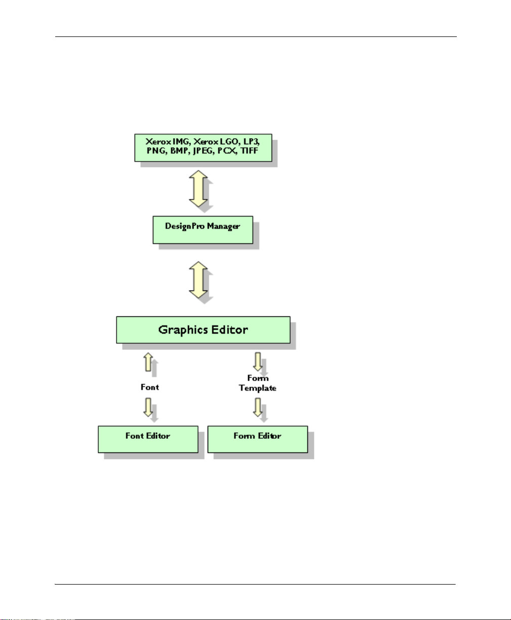
Graphics Editor and Other Elixir Products
DesignPro Tools for Xerox enables you to interconnect with other publishing products and
components. The figure below illustrates how DesignPro Graphics Editor can be
integrated into an overall publishing process.
Graphics Editor for Xerox and Other Elixir Products.
Chapter 1: Introduction 11

Interconnectivity Examples
The Converters application in DesignPro Manager converts image file formats such as
IMG (Xerox image), LGO (Xerox logo), LP3 (Elixir Legacy Graphic), BMP, JPEG, JPE,
JPG, PCX, and TIFF to Elixir format for use in DesignPro Graphics Editor.
The Converters application also converts a Xerox font to Elixir format, which you can
import for placement in an image using Graphics Editor.
Using DesignPro Graphics Editor, you can create and edit fonts, and load them directly by
tiling graphics into equal rectangles, each corresponding to a font character. Fonts created
in Graphics Editor can also be imported and edited in the DesignPro Font Editor, and then
converted to the Xerox format and printed on any Xerox printer.
Images created in Graphics Editor can then be used with DesignPro Form Editor to
enhance form appearance.
Associated DesignPro Applications
DesignPro Tools for Xerox employs integrated applications to provide advanced
functionality for creating resources such as documents, overlays, fonts and images for
Xerox jobs. Each application helps you create or modify one or more of these necessary
resources in a simple environment.
Following are the DesignPro Tools for Xerox applications:
DesignPro Manager: a Windows-based desktop program for managing and
converting resources to multiple supported formats. You can also open other
DesignPro Tools applications using the DesignPro Manager.
DesignPro Form Editor: an advanced overlay design tool used to create and edit
forms for Xerox printers.
DesignPro Font Editor: a complete font design application used for creating and
editing Xerox fonts as well as Elixir and PCL fonts. You can also open True Type
fonts in this editor.
DesignPro Graphics Editor: a full service bitmap editor providing various
transformations and commands for tiling images into raster fonts and image
modifications, such as resizing and cleaning up scanned images.
12 DesignPro Tools Graphics Editor® for Xerox User Guide

About this User Guide
The DesignPro Graphics Editor User Guide provides definitions and step-by-step
instructions to help you use this bitmap editor for tiling images into raster fonts and
creating or modifying images using various transformations and commands.
The guide is organized to mimic the image creation process. From the basic image
creation to editing and transforming and tiling the images, each chapter describes tasks in
the same order you can use when designing your images:
Chapter 1: Introduction
Introduces DesignPro Graphics Editor and basic image formats. Also introduces this
manual and identifies resources for finding answers and contacting Customer Support.
Chapter 2: DesignPro Graphics Editor Environment
Describes the Graphics Editor workspace. Included are instructions for customizing
Graphics Editor menus and toolbars.
Chapter 3: DesignPro Graphics Editor Basics
Explains basic DesignPro Graphics Editor operations, including creating and opening
images, and previewing images for printing.
Chapter 4: Drawing Objects
Explains how to use drawing and style tools in Graphics Editor and perform associated
operations.
Chapter 5: Editing Images
Provides an overview on image editing commands. Also explains using image change
commands, applying colors to images, setting image format properties. Brief overview of
user profiles is also given.
Chapter 6: Using Text and Transform Tools
Describes how to enter and modify text on images and tile images as fonts. Also provides
steps to transform images using different transform tools.
Appendix A: Workspace Quick Reference
Provides information on DesignPro Graphics Editor workspace environment menus and
toolbars.
Appendix B: Glossary
Alphabetical listing of product-specific or unique terms and abbreviations used in the
DesignPro Graphics Editor user guide.
Chapter 1: Introduction 13

Who Should Use this Guide?
This guide assumes you are already familiar with Microsoft Windows operations, printer
and font management operations and PC peripherals. You should also have access to
reference manuals for PC software and hardware, including any printers you are using for
the resource creation and print process.
Related Guides
If you require further information about a specific topic or wish to obtain product
background information, reference the following resources, all of which are part of the
DesignPro Tools for Xerox documentation package:
DesignPro Tools for Xerox Getting Started Guide.
DesignPro Tools Manager for Xerox User Guide.
DesignPro Tools Form Editor for Xerox User Guide.
DesignPro Tools Font Editor for Xerox User Guide.
DesignPro Tools for Xerox Migration Guide.
14 DesignPro Tools Graphics Editor® for Xerox User Guide
Conventions
Elixir products adhere to Microsoft Windows conventions for using menus, menu
commands, dialogs, command buttons, icons and mouse. See your Windows manual for
more information.
This guide uses the following typographic and symbolic conventions to identify special
information.
Typographic Conventions
This guide uses the following typographic conventions to identify special information.
Convention Information Type/Example
Bold type Te xt for you to enter.
Field names, windows, toolbars, buttons and workspace areas within a
task step.
Example:
down list
Example: click the Command tab.
Example:
Width and Height entry boxes
Example: select the Text tool.
Example: click OK to save settings.
Italic type References to other documents and books.
Example: refer to the DesignPro Tools for Xerox Getting Started
Guide.
select the required color mode from the Mode drop-
.
set the rounded box corner width and height in the
.
Chapter 1: Introduction 15
Symbolic Conventions
Look for the following symbols as you read through this guide to identify special
information.
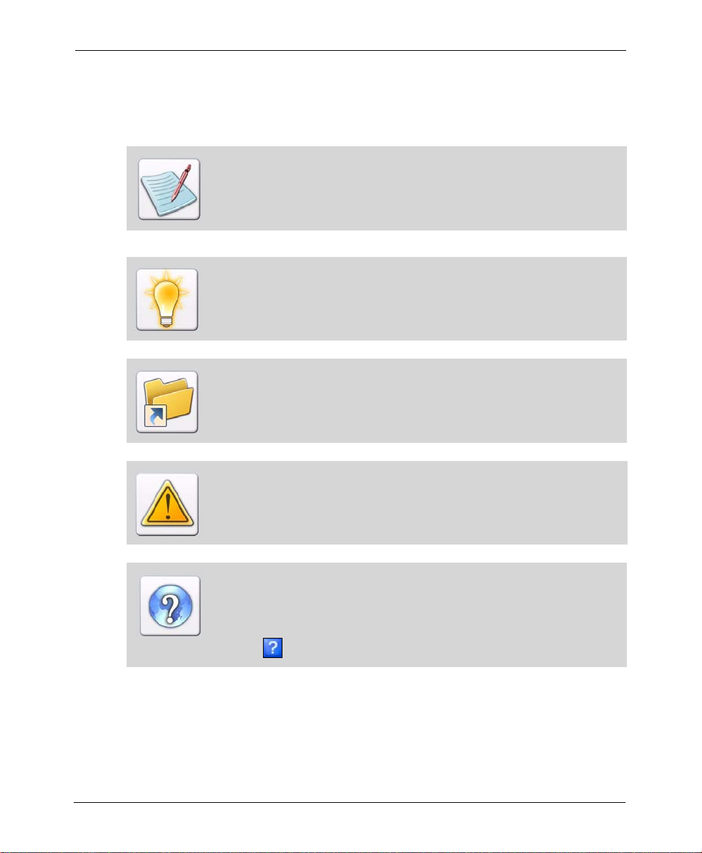
The Note symbol calls your attention to additional information.
The Tip symbol highlights a helpful tip.
The Shortcut symbol calls your attention to an easier way of accomplishing a
task.
The War ning symbol warns you of problems you might encounter.
The Question symbol refers you to the online help for more information.
To open online help:
From the Help menu, select Contents, or
Click in an open dialog.
16 DesignPro Tools Graphics Editor® for Xerox User Guide

Getting the Answers You Need
Elixir T echnologies provides you with multiple ways to learn and use DesignPro Graphics
Editor:
Customer Support (page 17)
Elixir Web Site Support (page 18)
Elixir Training (page 18)
Product Help (page 18)
Release Notes (page 19)
Customer Support
If you purchased this product directly from Elixir Technologies, you can contact the
Customer Support Center for your region at the number listed below.
If you have purchased this product from some other source, please contact the
authorized support representative from that source. Elixir provides customer
support for products purchased directly from Elixir.
North and South America:
+1 805 641 5900 ext. 3
Monday - Friday, 7:00 am to 4:00 pm Pacific Standard Time; if closed, press 2 to
reach Elixir’s extended Support coverage.
Elx_support@elixir.com
Asia Pacific:
Asia_support@elixir.com
Chapter 1: Introduction 17

Europe:
+44 (0) 207 993-4811
Monday - Friday, 6:00 am to 4:00 pm Central European Time
+1 805 641 5900 ext. 3
Monday - Friday, 4:00 pm to 2:00 am Central European Time
Europe_support@elixir.com
An Elixir Product Specialist will take your call and ask for the following information:
Your name, organization, telephone number and address.
Elixir product name and version number.
A complete description of the problem, including any error messages printed or
displayed on your monitor.
Elixir Web Site Support
You can obtain product support from the Elixir web page at www.elixir.com.
Select Support to:
Ask a question of Elixir Support.
Download the latest product releases and patches.
View the latest product Release Notes.
Sign up for Elixir Training.
Renew your product license.
Elixir Training
Elixir Technologies of fers training for its full range of Windows-based products. For more
information, contact Elixir Learning at +1 805 641 5900, ext. 4.
Product Help
Elixir software provides Online Help for all product functions and contains step-by-step
procedures that you can follow as you work:
Context-Sensitive Help can be activated from within the software for certain
dialogs by clicking in the upper-right corner of a dialog.
Online Help can be opened from the Help menu by selecting Contents.
18 DesignPro Tools Graphics Editor® for Xerox User Guide

Release Notes
Release Notes display at the start of product installation so you can review them before
beginning the installation process. Once installation completes, you can access Release
Notes from the product CD at drive:\Relnotes. There are two formats of the Release Notes
file, Relnotes.pdf and Relnotes.txt. The PDF file can be viewed using Adobe Reader. The
TXT file can be viewed using either Notepad or WordPad.
Chapter 1: Introduction 19

20 DesignPro Tools Graphics Editor® for Xerox User Guide

Chapter 2:
DesignPro Graphics
Editor Environment
In this chapter...
Opening Graphics Editor
What’s in the Workspace?
Workspace Tools
Basic Workspace Functions
Opening Graphics Editor
To open DesignPro Graphics Editor, from the Start menu select All Programs, Elixir
Applications, DesignPro To ols, DesignPro Graphics Editor.
21
What’s in the Workspace?
When you start Graphics Editor, the workspace displays where you can create and
maintain images and fonts. The Graphics Editor workspace displays the following main
components, depending upon which component you want to have open:
Design Area (page 23)
Toolbox (page 23)
Messages Window (page 23)
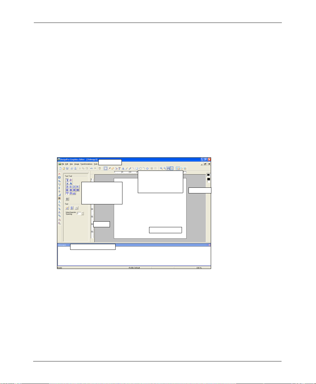
The image illustrates each part of the Graphics Editor workspace, when all the
components are open. You can customize the position and size of the windows to meet
your requirements. The workspace windows can be displayed as either floating or docked,
and can also be hidden from view.
Components of the DesignPro Graphics Editor.
Menu bar
Click buttons on
Toolbox contains
options for each
box tool
Tool bar to choose
commands quickly
Color bar
Ruler
Messages Window
Design Area
22 DesignPro Tools Graphics Editor® for Xerox User Guide
Design Area
The Design Area provides visual representation of the images. You can create, edit and tile
images; apply colors, patterns and transforms to the image; and print preview the image
within the Design Area. A Preview Area opens within the Design Area to preview the
patterns and images. The Design Area is scrollable vertically and horizontally. The Design
Area also magnifies the image by using the Zoom tool. For details, refer to the task “Using
the Zoom Tool” on page 103 in Chapter 5: “Editing Images” on page 89. At a certain
Zoom level, the Design Area also provides a Locator view to specifically locate or edit a
portion of the image.
Toolbox
T oolbox displays at the left of the Design Area by default. The Toolbox provides different
options associated with most toolbar items in the Drawing and the Transform toolbars.
Click on the toolbar item to view the associated options in the Toolbox. The Toolbox
updates each time you select a Drawing or Transform tool.
Messages Window
The Messages window is located at the bottom of the workspace by default and can be
docked to any other position. This window displays processing and compilation errors,
warnings and informational messages generated by the application. You can close the
Messages window from the menu by selecting View, Messages to allow more space to
work.
You can perform any of the following functions to view or hide the Messages
window:
Check/uncheck Messages from the View menu.
Press Ctrl+Shift+M on the keyboard.
However, the Messages window will automatically re-display whenever a
message is generated by the application.
You can view messages in pop-up message boxes alternatively.
Select Tools, Options. The Options dialog displays. From the General
category, uncheck Send All Messages To Window.
You can also click at the top of the Messages window.
Chapter 2: DesignPro Graphics Editor Environment 23
Clearing Messages
To clear the messages generated by the application, right-click in the Messages window
and select Clear Messages from the pop-up menu.
You can also clear messages in this window by pressing Control + D or by
selecting Clear Messages from the View menu.
Copying Messages
To copy the messages generated by the application:
1 Select the required messages in the Messages window.
2 Right-click the selected messages and select Copy Messages from the pop-up menu.
The selected messages copy to the clipboard and you can paste them wherever
required.
You can also copy messages from this window by selecting the required
messages and pressing Control + C on the keyboard.
24 DesignPro Tools Graphics Editor® for Xerox User Guide
Logging Messages
Logging options enable you to save the information displayed in the Messages window in
a text file.
To log the generated messages:
1 From the Tools menu, select Options.
The Options dialog displays.
2 Select the Messages category, and check Log to File.
This writes messages to the log file.
Options set at the application level apply to all projects created in the
application.
3 In the entry box adjacent to Log to File, enter the destination path for the log file.
The default value of “.\” saves the log file in the same directory as the resource
file.
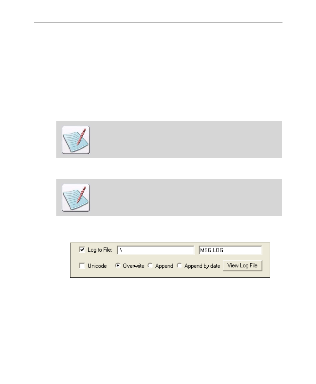
4 Enter the name of the log file in the next entry box, as shown below:
The default log file name is “MSG .LOG”, however, you can change the file name and
save it.
5 Check Unicode to create the log file using the Unicode character set.
6 Specify the settings of your choice:
Overwrite: overwrites any existing log file messages.
Append: appends messages to the existing log file.
Append by date: appends messages to the log file by date.
Chapter 2: DesignPro Graphics Editor Environment 25
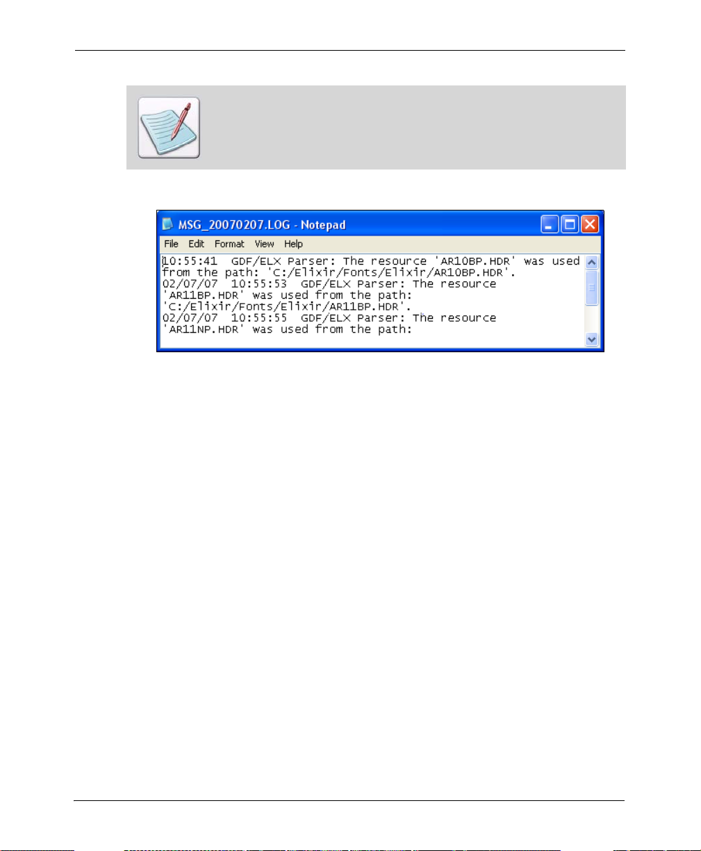
You can view the log file at any time by clicking View Log File. The contents of
the log file (with the name and location entered in the Log to File entry boxes)
display in a Notepad window.
You can create a message log file in any format.
The Log file displaying the generated messages and the system date value is
appended to the name of the file due to the Append by date option.
7 Click Apply, and then click OK.
Displaying Message Time and Date
You can also display the time and date when a message was generated in the Messages
window.
To display message time and date:
1 From the Tools menu, select Options.
The Options dialog displays.
2 Select the Messages category.
3 Under the Messages to View area, check Information to display informational
messages in the Messages window.
4 Under the Show area, check Message Time in order to display the message
generation time in the Messages window.
5 Under the Show area, check Message Date in order to display the message
generation time in the Messages window.
6 Click Apply and then click OK.
26 DesignPro Tools Graphics Editor® for Xerox User Guide
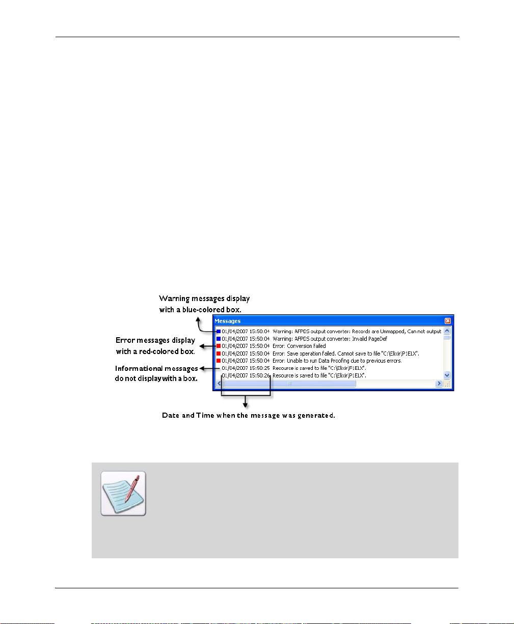
Color Coding Messages
Messages in the Messages window can also be color coded according to the nature of the
message. Color coding is added using colored boxes before the messages. Error messages
display red boxes, warnings display blue boxes, and informational messages display
neither. With color coding, critical messages can be located quickly.
To color code messages:
1 From the Tools menu, select Options.
The Options dialog displays.
2 Select the Messages category.
3 Under the Messages to View area, make sure Information is checked to display
informational messages in the Messages window.
4 In the Show area, check Use Color to display colored boxes in the Messages
window.
5 Click Apply and then click OK.
The Messages window.
You can also set the number of maximum lines displaying in the Messages
window by entering the number in the Lines Maximum entry box, provided in
the Show area.
If the number of messages generated exceeds the value specified in the Lines
Maximum entry box, the new messages overwrite the existing ones from the
top in the Messages window. If Log to File is checked, messages are
overwritten from the top of the log file.
Chapter 2: DesignPro Graphics Editor Environment 27
Workspace Tools
Graphics Editor provides toolbars for easy access to the most commonly used application
commands. You can perform standard Windows operations to hide or display a toolbar, or
dock a toolbar at the edge of the workspace.
Menus
A menu bar with drop-down menus displays directly below the application title bar. These
drop-down menus provide both standard MS-Windows and application-specific options.
Selecting a menu performs an associated action or displays a submenu or a dialog. See
“Menu bar” on page 151 in Appendix A: “Workspace Quick Reference” on page 151 for
detailed information on all of the menus.
To o l b a r s
Directly below the menu bar are toolbars with buttons that provide access to the most
commonly used commands and tools. You can hide or display toolbars from the View
menu by selecting Toolbars, required toolbar. See “Toolbars” on page 158 in Appendix A:
“Workspace Quick Reference” on page 151 for detailed information on tools in the
toolbar.
To add or remove more buttons on a toolbar, see “Adding Buttons to Toolbars”
on page 32.
To view or hide a toolbar, see “Customizing Toolbar Display” on page 30.
28 DesignPro Tools Graphics Editor® for Xerox User Guide
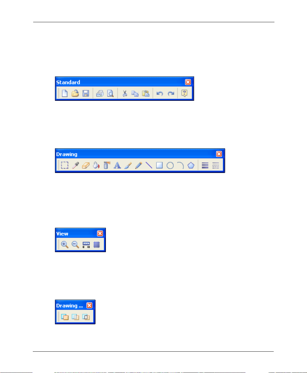
Standard Toolbar
The Standard toolbar provides one-click access to the basic File and Edit menu
commands, such as Saving an Image (page 50) or Previewing and Printing Images (page
53). For more information, refer to “Standard Toolbar” on page 159 in Appendix A:
“Workspace Quick Reference” on page 151.
Drawing Toolbar
The Drawing toolbar provides one-click access to the Drawing Objects (page 60). For
more information, refer to “Drawing Toolbar” on page 160 in Appendix A: “Workspace
Quick Reference” on page 151.
View Toolbar
The View toolbar provides one-click access to the basic View menu commands such as
using the Ruler and Grid tools or Zooming In and Out (page 103) within the Design Area.
For more information, refer to “View Toolbar” on page 161 in Appendix A: “Workspace
Quick Reference” on page 151.
Drawing Modes Toolbar
The Drawing Modes (page 60) toolbar provide options to select the required drawing
mode for an image. For more information, refer to “Drawing Modes T oolbar” on page 162
in Appendix A: “Workspace Quick Reference” on page 151.
Chapter 2: DesignPro Graphics Editor Environment 29
Transform Toolbar
The Transform toolbar contains transform tools to apply transformations to an image. For
more information, refer to “Transform Toolbar” on page 163 in Appendix A: “Workspace
Quick Reference” on page 151.
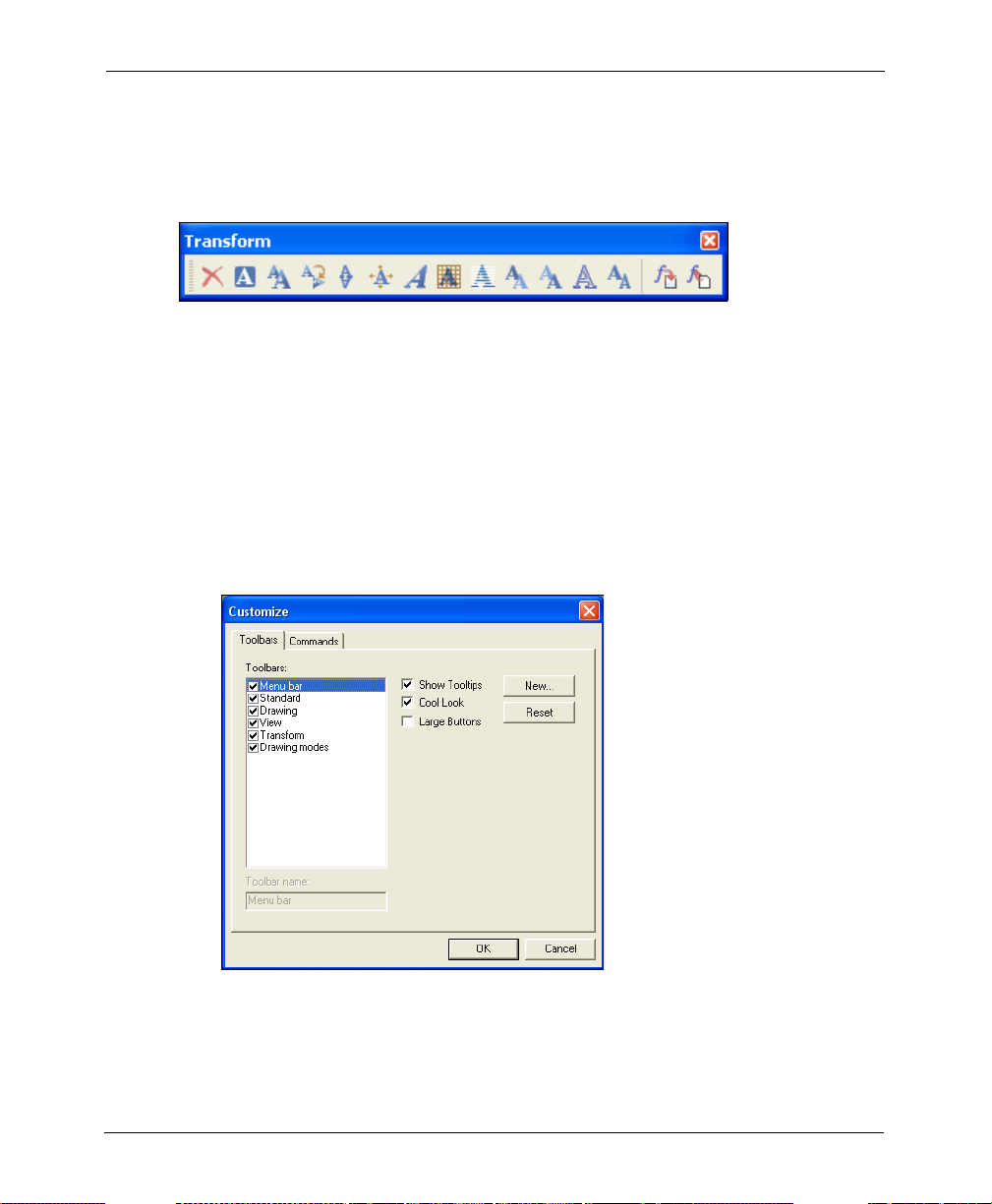
Customizing Toolbar Display
You can also specify the toolbars that display in the workspace.
T o customize Graphics Editor toolbars:
1 From the View menu, select Toolbars, Customize.
The Customize dialog displays.
2 Click the Toolbars tab.
The Toolbar Options displays.
3 Check the toolbars you want to display in the workspace from the list of available
toolbars.
The selected toolbar name displays in the Toolbar Name entry box.
30 DesignPro Tools Graphics Editor® for Xerox User Guide
You cannot uncheck Menu bar from the list of toolbars.
You can also display a toolbar from the View menu by selecting Toolbars,
required toolbar.
4 To set the appearance of the displayed toolbars, specify the fo llowing:
Show Tooltips: displays the tool tips associated with the toolbar buttons.
Cool Look: displays the toolbar buttons in the smooth look mode.
Large Buttons: displays the toolbar buttons in the enlarged mode.
Reset/Delete: resets a default toolbar to the default settings. This button toggles
to Delete when a custom toolbar is selected; only custom toolbars can be deleted.
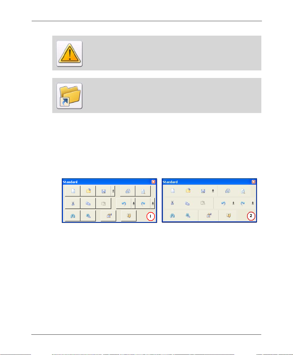
The Standard toolbar with Large Buttons and (1) Cool Look un-checked and (2)
Cool Look checked.
5 Click OK to return to the application window.
Chapter 2: DesignPro Graphics Editor Environment 31

Creating a New Toolbar
Using Graphics Editor, you can also create a new toolbar.
To create a new toolbar:
1 From the View menu, select Toolbars, Customize.
The Customize dialog displays.
2 Click the Toolbars tab.
3 Click New to display the New Toolbar dialog.
4 In the Toolbar Name entry box, enter the name of the new toolbar.
You can modify this name later in the Toolbars tab.
The names of the default toolbars are not editable.
5 Click OK.
The new toolbar displays in the workspace. The new toolbar is currently empty. To
add buttons to this toolbar, see “Adding Buttons to Toolbars” on page 32.
Adding Buttons to Toolbars
You can also add buttons to your toolbar.
T o add buttons to a toolbar:
1 From the View menu, select Toolbars, Customize.
The Customize dialog displays.
32 DesignPro Tools Graphics Editor® for Xerox User Guide

2 Click the Command tab.
The list of available command groups displays in the Categories list. When a
command group is selected in the Categories list, the buttons for each command in
the group display in the Buttons area.
3 Click and drag the required button to any target toolbar displaying in the Design
Area, and then release the mouse.
While dragging the required button, the mouse cursor changes from to . The
selected button is then added to the required toolbar at the specified place.
If you drag a button and drop it anywhere in the application window other than
the target toolbar, Graphics Editor automatically creates a new toolbar with the
specified button and displays it in the application window. If you then click the
Toolbars tab, the newly created toolbar name (default is Toolbar 1) displays in
the Toolbars list.
4 Click OK.
The added buttons display in the selected toolbars.
Chapter 2: DesignPro Graphics Editor Environment 33

Status Bar
The Status bar displays, by default, along the lower edge of the Graphics Editor
workspace. When you move the mouse pointer over the Design Area, the Status bar
displays the current position of the mouse pointer and the zoom level. The Status bar also
displays the tooltip when the mouse pointer is placed over a command.
In addition, when an object is being drawn in the Design Area, the Status bar also displays
the tooltip of the object being drawn, the height, width, and the current coordinates of the
mouse pointer. This information helps in drawing objects in the Design Area.
Zoom Level
Tooltip
Current Mouse Position
Object Size
Grid
The grid feature in Graphics Editor provides a network of intersecting lines that help in
aligning and placing objects in the Design Area. These lines help when creating images in
the design process, but are not part of the finished image.
Design Area with the Grid option enabled.
34 DesignPro Tools Graphics Editor® for Xerox User Guide
Displaying and Hiding the Grid
To activate the grid in the Design Area, select View, Grid from the menu.
You can also view and hide the grid by clicking on the View toolbar or by
pressing F4.
The grid is only active when the zoom is set to 800% or greater.
Setting Grid Color
To specify grid color:
1 From the Tools menu, select Options.
The Options dialog displays.
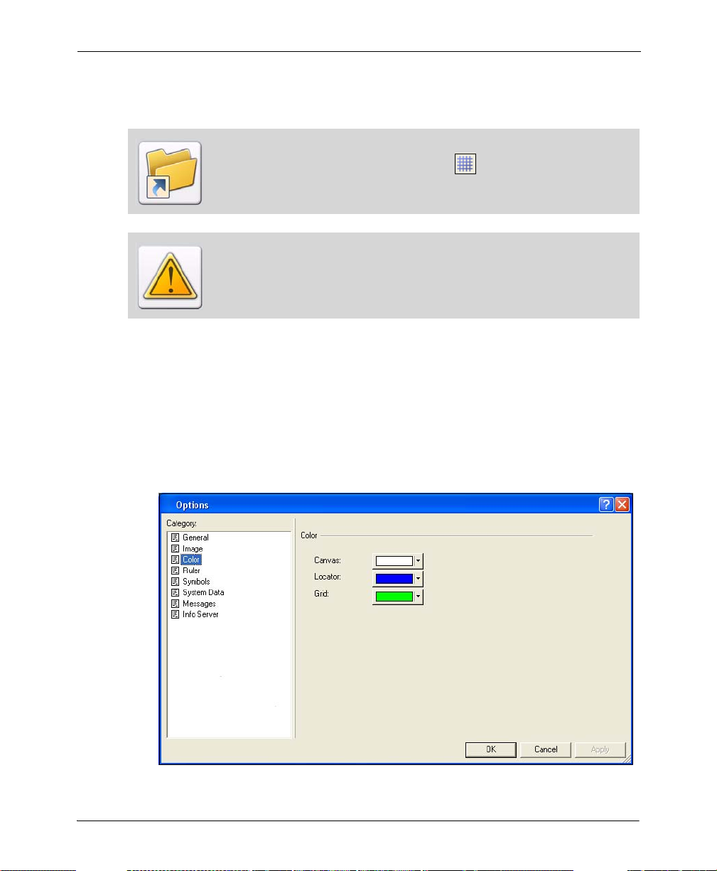
2 Select the Color category.
Color Category.
Chapter 2: DesignPro Graphics Editor Environment 35

3 Click the Grid button and do one of the following:
Click on the
Select the required color from the drop-down palette
Or
Click Other from the drop-down palette to open the Color dialog.
You can select a custom color for the grid from the Color dialog.
Default colors.
User-defined
Custom colors.
You can preview the
selected color.
required color.
The image above explains how to use the color dialog to select a custom color.
4 Click OK.
The color of the grid changes as specified.
You can specify
the required
shade of the
selected color.
36 DesignPro Tools Graphics Editor® for Xerox User Guide

Ruler
Graphics Editor provides horizontal and vertical rulers to help accurately place an object
in the Design Area. Rulers display along the top and left sides of the Design Area. When
you move an object or cursor in the Design Area, lines indicating the object or cursor
position appear on the rulers. You can show or hide the rulers and change the unit of
measurement used in the rulers.
Design Area with the Ruler option enabled.
Displaying and Hiding the Ruler
You can view/hide the ruler by:
Selecting Ruler from View the menu.
Clicking on the Zoom toolbar.
Pressing F2 on the keyboard.
Chapter 2: DesignPro Graphics Editor Environment 37

Setting Ruler Units
You can change the unit of measurement used for the horizontal and vertical rulers.
To specify the required unit of measurement:
1 From the Tools menu, select Options.
The Options dialog displays.
2 Select the Ruler category.
Ruler Category.
3 Select the required unit of measurement from the Units drop-down list and click
OK.
The new ruler settings will be applicable after re-opening the application.
38 DesignPro Tools Graphics Editor® for Xerox User Guide

Basic Workspace Functions
The Graphics Editor workspace also has some basic functions to help you design your
images.
Using the Right Click Menu
The right-click menu provides access to the most commonly used functions in Graphics
Editor. To use the right-click menu, position the cursor in the Design Area and right-click
the mouse. A pop up menu displays. This menu is context-sensitive and displays a list of
options depending on the object selected in the workspace. Select the required option from
the menu.
Choosing Commands
A command instructs Graphics Editor to perform a specific action. You can choose a
command by either:
Clicking a toolbar button.
Selecting a menu option.
Using a hot key.
Using a shortcut key.
In the chapters that follow, command selection is described using the most common
method for the described task. However, any related command selection can be used to
accomplish the same instruction.
Chapter 2: DesignPro Graphics Editor Environment 39

Undoing and Repeating Commands
Graphics Editor keeps track of your editing and formatting changes. If you want to undo a
change or command selection, you can reverse several previous actions.
Click Redo to repeat the
last reversed action
Click Undo to reverse
the last action
Using the Standard toolbar to Undo and Repeat commands.
You can use the Control + Z and Control + Y shortcut keys to perform undo and
redo actions respectively.
You can also select either Redo or Undo from the Edit menu
40 DesignPro Tools Graphics Editor® for Xerox User Guide

Chapter 3:
DesignPro Graphics
Editor Basics
In this chapter...
Managing Images
Previewing and Printing Images
Managing Images
DesignPro Graphics Editor opens, displ a ys, creates and prints images. You can also
change the file type and attributes of images. These functions are discussed in the
following sections:
Opening an Image (page 43)
Arranging Images in the Design Area (page 44)
Creating an Image (page 45)
Changing Image Attributes (page 48)
Saving an Image (page 50)
Resetting an Image (page 51)
Setting Image Parameters (page 52)
41

DesignPro Graphics Editor opens and saves images in the following input and output
formats:
Input Formats (Open):
Bitmaps (BMP)
Elixir Legacy Graphic (LP3)
Includes Legacy and DesignPro Tools images; both use the same extension.
JPEG Files (JPG, JPE, JPEG)
PCX Files (PCX)
PNG File (PNG)
TIFF Files (TIF)
Xerox IMG (IMG)
Xerox LGO (LGO)
Output Formats (Save As):
Bitmaps (BMP)
Elixir Images (LP3)
Elixir Form (EFR)
JPEG Files (JPG, JPE, JPEG)
PCX Files (PCX)
PNG File (PNG)
TIFF Files (TIF)
Xerox IMG (IMG)
Xerox LGO (LGO)
42 DesignPro Tools Graphics Editor® for Xerox User Guide
Opening an Image
To open an image:
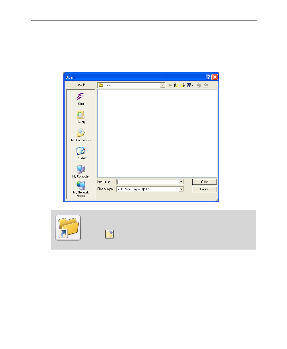
1 From the File menu, select Open.
The Open dialog displays.
You can also use one of the following methods to open an image in the Design
Area:
Click on the Standard toolbar.
Press Control + O.
2 Select the required file type from the Files of Type drop-down list.
Selecting the Elixir icon in the left dialog pane automatically locates the target folder
based on the selected file type. For example, when you select Xerox IMG (*.img)
from the Files of Type drop-down list, and then select Elixir from the side pane, the
default path for the Xerox image is automatically set to drive:\Elixir\Pics\IMG.
Chapter 3: DesignPro Graphics Editor Basics 43
By default, you can select only image-specific file types from the Files of Type
drop-down list. However, you can choose to include the All Files (*.*) option to
the Files of Type drop-down list to select any file type. From the Tools menu,
select Options to open the Options dialog. Select the General category and
check Allow All Files in Fileselectors. Click OK to return to the Design
Area.
3 Select the required image and click Open.
The image will open in the Design Area. In Graphics Editor, most tools and options
are enabled only if an image is open in the Design Area.
To open multiple images in the Design Area, repeat steps 1 to 3. The images are
displayed in separate windows within the Design Area. The number of images
open in the Design Area at one time is limited depending on the availability of
system memory.
Arranging Images in the Design Area
If you have multiple images opened in the Design Area, you can arrange the images using
options provided in the Graphics Editor Windows menu.
To arrange images in the Design Area:
1 Open the image(s) in the Design Area.
2 Select one of the following options from the Window menu.
Cascade: displays the image windows stacked and cascading from the upper left
to the lower right of the screen.
Tile: displays all image windows edge to edge.
Arrange All: arranges all image windows from top to bottom on the screen.
The image windows are arranged as specified.
44 DesignPro Tools Graphics Editor® for Xerox User Guide

Creating an Image
Graphics Editor creates images in Bitmaps (BMP) or Elixir Images (LP3) image formats
only. However, images can be converted and saved in different formats as mentioned in
“Managing Images” on page 41.
To create a new image:
1 From the File menu, select New.
The New dialog displays.
You can also use one of following methods to open the New dialog:
Click on the Standard toolbar.
Press Control + N.
2 Enter the file name in the Name entry box.
3 From the Format drop-down list, select the required format.
You can select either BMP or LP3. You can also select the required format from the
Attributes dialog. For more information, refer to the task “Setting Image Parameters”
on page 52.
Chapter 3: DesignPro Graphics Editor Basics 45

4 From the Paper Type drop-down list, select the appropriate size.
The image size depends on the selected paper size. The size of the image created can
be changed later using the Resize tool in the Transform toolbar.
Refer to the task “Resizing an Image” on page 137 in Chapter 6: “Using Text and
Transform Tools” on page 121 for more information on the Resize tool.
5 Specify the image width and height in the Width and Height entry boxes.
The Width and Height e nt ry boxes are enabled only if Other Paper Type is selected
from the Paper Type drop-down list.
6 From the Units drop-down list, select the required unit of measurement.
Measurement can be in pixels, inches, centimeters, or millimeters. The specified unit
is used for both graphic and digital rulers.
You can also edit the ruler parameters after creating the image. For more on
setting ruler parameters, see “Ruler” on page 37 in Chapter 2: “DesignPro Graphics
Editor Environment” on page 21.
7 Select the required color model from the Model drop-down list.
The options available for BMP format are Black & White, 16 Color, 256 Color,
and True Color.
The options available for LP3 format are Black & White, Highlight Color, and
Full Color.
Color models are methods or conventions for representing color in desktop
publishing and graphic arts.
The image size depends on the selected color model.
For LP3 image format, perform additional step 8.
8 Select the required highlight color from the Highlight Color drop-down list.
This list is enabled only when the LP3 image format and the Highlight Color mode
are selected from the Format and Model drop-down lists mentioned earlier. The
available colors in the list depend on the catalog selected from the Options dialog.
46 DesignPro Tools Graphics Editor® for Xerox User Guide

9 Select Horizontal or Vertical resolution options or enter a custom value using the
Other entry box.
This option is enabled only if Other is selected from either Horizontal or Vertical
image resolution options.
When a new highlight color is selected, the highlight color used throughout the
image is changed.
Increasing the image resolution increases the image print size and vice versa. The
Vertical and Other entry boxes are disabled for the LP3 format.
Click Restore Defaults to restore the default values for creating an new image.
10 Click OK to return to the Design Area.
Most of the properties set in the New dialog can be changed later. For more
information, refer to the task “Changing Image Attributes” on page 48 later in
this chapter.
Chapter 3: DesignPro Graphics Editor Basics 47

Changing Image Attributes
To change image attributes:
1 From the Image menu, select Properties.
The Attributes dialog displays.
The Shortcut symbol calls your attention to an easier way of accomplishing a
task.
2 From the Format drop-down list, select the required format.
You can select either BMP or LP3.
3 From the Units drop-down list, select the required unit of measurement.
You cannot change the image size in this dialog. You can, however, change the
image size using the Resize tool. Refer to the task “Resizing an Image” on page 137
in Chapter 6: “Using Text and Transform Tools” on page 121 for more information
on the Resize tool.
Measurement can be in pixels, inches, centimeters, or millimeters. The unit specified
in this dialog is used for both graphic and digital rulers.
48 DesignPro Tools Graphics Editor® for Xerox User Guide

4 Select the required color model from the Model drop-down list.
The options available for BMP format are Black & White, 16 Color, 256 Color,
and True Color.
The options available for LP3 format are Black & White, Highlight Color, and
Full Color.
Color models are methods or conventions for representing color in desktop
publishing and graphic arts.
The image size depends on the selected color model.
For LP3 image format, perform additional step 5.
5 Select the required highlight color from the Highlight Color drop-down list.
This list is enabled only when the LP3 image format and the Highlight Color mode
are selected from the Format and Model drop-down lists mentioned earlier. The
available colors in the list depend on the catalog selected from the Options dialog.
When a new highlight color is selected, the highlight color used throughout the
image is changed.
6 Select the Horizontal or Vertical resolution options or enter a custom value using
the Other entry box.
Increasing the image resolution increases the image print size and vice versa. The
Vertical and Other entry boxes are disabled for the LP3 format. This option is
enabled only if Other is selected from either Horizontal or Vertical image resolution
options.
7 Check Resample Image to increase/decrease image resolution in dpi without
affecting the actual image size.
8 Click OK to save changes to the image.
Chapter 3: DesignPro Graphics Editor Basics 49

Saving an Image
To save an image:
1 From the File menu, select Save.
The Save As dialog displays.
2 From the Save As drop-down list, Select the required file type.
Selecting the Elixir icon in the left dialog pane automatically locates the target folder
based on the selected file type. For example, when you select Xerox IMG (*.img)
from the Save As drop-down list, and then select Elixir from the side pane, the
default path for the Xerox image is automatically set to drive:\Elixir\Pics\IMG.
3 Click Edit Property Settings to modify output property settings.
This displays either the Image or Xerox LPS Resource Writer property dialog,
depending on the file type selected in the Save As drop-down list.
50 DesignPro Tools Graphics Editor® for Xerox User Guide

4 Review and edit the settings if required.
For information on all of the Output Format options, click available on top-right
of the respective converter dialog.
You can also edit property settings by clicking in the Save As dialog.
You can also restore the default settings of the application by clicking either
Restore Default Settings or in the Save As dialog.
These options are not available for the Elixir Legacy Graphic (LP3) file format.
5 Enter the File Name and click Save to return to the Design Area.
You can also use one of following methods to save an image in the Design Area:
Click on the Standard toolbar.
Press Control + S.
Resetting an Image
You can reset an image and remove all edits since the last save operation.
To reset an image:
1 Select Reset from the Image menu.
The Reset option is available only if an image is open in the Design Area.
2 Click Yes to return to the Design Area.
You can also press Control + Alt + R to reset an image.
Chapter 3: DesignPro Graphics Editor Basics 51

Setting Image Parameters
Default image attributes such as color model, format and mode can be set that are applied
every time you create a new image.
To set default image parameters:
1 From the Tools menu, select Options.
The Options dialog displays.
2 Select the Image category.
Graphics Editor always employs the default RGB color model. You can specify
different color models when saving an image.
3 Select either BMP or LP3 as the image Format.
4 Select the required color Mode.
The options available for BMP format are Black & White, 16 Color, 256 Color, and
True Color. The options available for LP3 format are Black & White, Highlight
Color, and Full Color.
52 DesignPro Tools Graphics Editor® for Xerox User Guide

If you choose the LP3 color format, then perform steps 5 and 6.
5 Select the required catalog from the options available in the Catalog Name drop-
down list.
The colors associated with the selected catalog are displayed in the Highlight Color
drop-down list. This list is enabled only when LP3 image format and Highlight Color
mode are selected above.
6 Select either Red, Green or Blue from the Highlight Color drop-down list.
This list is enabled only when LP3 image format and Highlight Color mode are
selected.
7 Click Apply to save the setting changes.
These changes are applied only when the image is reopened or when a new image is
created.
Previewing and Printing Images
After creating an image, you can set paper properties, preview the image within the
Design Area and make final changes before printing. These functions are discussed in the
following sections:
Specifying Paper Properties (page 54)
Print Previewing an Image (page 55)
Printing an Image (page 56)
Printing a Portion of an Image (page 57)
You can print an image or portion of an image directly using Graphics Editor or use the
image as a resource in an overlay or another application.
Chapter 3: DesignPro Graphics Editor Basics 53

Specifying Paper Properties
Before printing an image, you can specify paper properties such as page orientation and
size. You can also add margins to your page with specified sizes.
To set paper properties:
1 From the File menu, select Page Setup.
The Page Setup dialog displays.
2 Under the Paper area, select the required paper size from the Size drop-down list.
3 Under the Orientation area, select the required page orientation.
You can select either Portrait or Landscape.
4 Under the Margins area, check Add Margins and select the required value from the
Margin Units drop-down list.
5 Enter the Left, Right, Top, and Bottom margin size, per specified unit of
measurement.
6 Click OK.
The paper settings are saved and will be applied when the image is printed.
54 DesignPro Tools Graphics Editor® for Xerox User Guide

Print Previewing an Image
The print preview feature displays an image exactly as it will look when printed.
To print preview an image:
1 From the File menu, select Print Preview.
The current image displays in the preview window.
The image above shows a print preview of the current image in Graphics Editor.
2 As appropriate, click any of the following:
Print: displays the Print dialog for setting the print properties.
Next Page: displays the next page. This option is activated only if the image
consists of more than one page.
Prev Page: displays the previous page. This option is activated only if the image
consists of more than one page.
One/Two Page: displays one or two pages at a time. This option is activated only
if the image consists of more than one page.
Zoom In: increases the magnification of the current page.
Zoom Out: decreases the magnification of the current page. This option is
activated only if the Zoom In was previously selected.
3 Click Close to exit print preview and return to the previous view of the image.
Chapter 3: DesignPro Graphics Editor Basics 55

Printing an Image
To print an image:
1 From the File menu, select Print.
The Print dialog displays.
The Print option is activated only if an image is open in the Design Area.
2 Select the required printer from the Name drop-down list.
Information about the selected printer is displayed underneath this list.
3 Click Properties to set properties associated with a printer.
4 Check Print to File to print a document to a file instead of routing it to a printer.
When this option is selected, the resource is saved with the printer formatting, such
as font selection and color specifications, in a PRN file that can be printed at a later
time.
When Print to File is selected while printing, the resource is saved with the
selected printer driver specifications. The PRN file generated could be printed
later on a printer having the same or a compatible printer diver, otherwise the
PRN file will not print correctly.
5 Select any of the following in the Print Range area:
All: prints all available pages. This option is selected by default.
Pages: prints a range of pages specified in the From and To entry boxes.
Selection: prints selected contents of the current page only.
56 DesignPro Tools Graphics Editor® for Xerox User Guide

6 Enter the number of copies to be printed in the Number of Copies entry box.
7 Check Collate option to print a complete copy of the file before the first page of the
next copy is printed.
The Collate option is activated only if a value greater than 1 is specified in the
Number of Copies entry box.
8 Click OK to print the image.
You can also use one of the following methods to print an image:
Click on the Standard toolbar.
Press Control + P.
Printing a Portion of an Image
To print a selected portion of an image:
1 Select the required image area.
2 From the File menu, select Page Setup.
The Page Setup dialog displays.
3 From the Selection area, select Selected Area Only.
4 Specify other printing preferences and click OK to print the image.
For more information on printing an image, refer to the task “Printing an Image”
on page 56.
Chapter 3: DesignPro Graphics Editor Basics 57

58 DesignPro Tools Graphics Editor® for Xerox User Guide

Chapter 4:
Drawing Objects
In this chapter...
Using the Drawing Tools
Filling Objects
Enhancing Objects with Style Tools
Working with Patterns
Drawing Modes
Using the Drawing Tools
Graphics Editor drawing tools are located on the Drawing toolbar. The tools are active
only when an image is open in the Design Area.
When you click a drawing tool, the Toolbox changes accordingly and displays associated
options for the selected tool. Click another tool, and new tool options replace the previous
selection.
59

Clicking the Line tool
displays the associated
options in the Toolbox.
You can view a sample of your
selections in the Preview Area
of the Toolbox.
Toolbox options for the selected tool.
Using the different drawing tools are explained in the following topics:
Drawing Objects (page 60)
Filling Objects (page 72)
Erasing Objects (page 79)
Enhancing Objects with Style Tools (page 80)
Working with Patterns (page 83)
Drawing Modes (page 86)
Drawing Objects
Graphics Editor provides six tools for drawing the following shapes: lines, ellipses, boxes,
curves, polygons/polylines, and freehand form figures. Objects are drawn by clicking the
required tool, and then dragging the mouse in the Design Area. Line width and styles can
also be set while drawing the objects. You can also use the tools in a magnified view of the
Design Area.
60 DesignPro Tools Graphics Editor® for Xerox User Guide

Using the Pencil
You can use the Pencil tool to draw hard-edged freehand lines with the current foreground
color.
To draw a free form line:
1 Click on the Drawing toolbar.
The Toolbox displays the associated options.
You can also draw a free form line by selecting Pencil from the Tools menu.
2 Select the required pencil tip from the following:
draws individual dots or a continuous line with squared ends.
draws individual dots or a continuous line with rounded ends.
The figure below illustrates squared and rounded pencil tips:
Squared
Rounded
Samples of pencil drawing with square and rounded tips.
To clearly view the difference between a square and rounded pencil tip, select a
line width of 5 dots or more.
Chapter 4: Drawing Objects 61
Drawing Lines
You can use the Line tool to draw single, connected, and radial lines.
To draw a straight line:
1 Click on the Drawing toolbar.
The Toolbox displays the associated options.
You can also draw a line by selecting Line from the Tools menu.
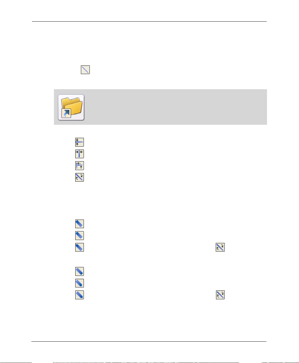
2 Select the line direction from the following:
draws line in horizontal direction only.
draws line in vertical direction only.
draws line in horizontal or vertical direction.
draws line in any direction, including diagonal.
Horizontal and vertical line options are useful when drawing lines on large images
that otherwise do not fit in the Design Area. When drawing connected lines,
scrolling around the image will not disconnect the line from the last point.
3 Select the line beginning style from the following:
draws line with squared beginning.
draws line with rounded beginning.
draws line with mitered beginning; enabled only when is selected.
4 Select the required line end style from the following:
draws line with squared end.
draws line with rounded end.
draws line with mitered end, and is enabled only when is selected.
62 DesignPro Tools Graphics Editor® for Xerox User Guide

5 Select the required line thickness and style. For more information, see “Line Width
and Line Style” on page 82.
Line beginning and end styles are most apparent at a line width of 10 or above. The
figure below illustrates the effects of squared, rounded, and mitered ends.
Squared
Rounded
Mitered
Line end examples.
6 Select the required line style from the following:
draws a single line between mouse clicks.
connects lines between successive mouse clicks until another line style or
drawing tool is selected. This option is enabled only when is selected.
draws lines radiating from a single point; enabled only when is selected.
Line style examples.
Chapter 4: Drawing Objects 63

7 Select the required line thickness and style. For more information, see “Line Width
and Line Style” on page 82.
You can also change the line properties and widths while drawing a line, as
illustrated in the figure below:
Connected Lines with Different Widths.
Drawing Boxes
You can use the Box tool to draw hollow or filled squares or rectangles with squared or
rounded corners.
T o draw a box:
1 Click on the Drawing toolbar.
The Toolbox displays the associated options.
You can also draw a box by selecting Box from the To o l s menu.
2 Select the box shape from the following:
draws a square.
draws a rectangle.
64 DesignPro Tools Graphics Editor® for Xerox User Guide
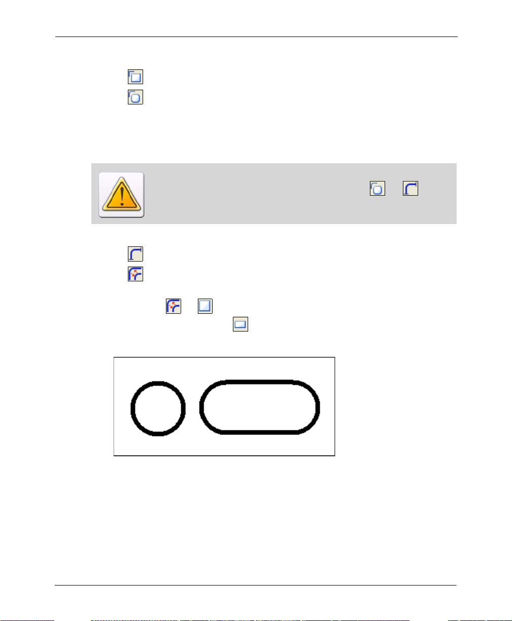
3 Select the box corner type from the following:
draws a square cornered box.
draws a round cornered box. Selecting this tool displays the associated
options in the Toolbox.
4 Set the rounded box corner width and height in the Width and Height options.
The value can be specified between 1 and 500.
The Width and Height entry boxes are enabled only when and is
selected.
5 Select the required rounded box corner type from the following:
uses custom box corner dimensions.
draws a square or rectangle with rounded corners in half height and width
dimensions.
If you select for , corners are rounded off to the maximum, resulting in a
complete circle. Whereas for , a rectangle is drawn with two sides com pletel y
rounded off. The figure below illustrates the difference:
Examples of complete and half circles.
Chapter 4: Drawing Objects 65

6 Select the required box fill option from the following:
draws an empty box.
draws a box using the selected background color.
draws a box with fill pattern selected from the Select Pattern dialog. For
more information on selecting patterns, see “Working with Patterns” on page 83.
7 Select the required box border thickness and style. For more information, see “Line
Width and Line Style” on page 82.
Box Style Examples.
Note that square boxes appear distorted when the screen aspect ratio is not 1:1; however,
boxes will print correctly.
66 DesignPro Tools Graphics Editor® for Xerox User Guide

Drawing Circles/Ellipses
You can use the Circle tool to draw hollow or filled circles and ellipses.
To draw a circle or an ellipse:
1 Click on the Drawing toolbar.
The Toolbox displays the associated options.
You can also draw a circle/ellipse by selecting Circle/Ellipse from the Tools
menu.
2 Select either a circle or an ellipse from the following:
draws a circle.
draws an ellipse.
3 Select the drawing origin of the circle/ellipse origin from the following:
draws circle/ellipse from anchor point at the center.
draws circle/ellipse expanding outward with one quadrant remaining
anchored in the start position. This helps to place the shape more precisely in
relation to another object.
4 Select from the following circle/ellipse segment options:
draws circle/ellipse upper left quarter.
draws circle/ellipse upper right quarter.
draws circle/ellipse lower left quarter.
draws circle/ellipse lower right quarter.
A complete circle or an ellipse can only be drawn when all of the four circle/ellipse
quarter options are selected.
Chapter 4: Drawing Objects 67

5 Select the circle/ellipse fill option from the following:
draws empty circles and ellipses.
draws circles and ellipses using the selected background color.
draws a circle/ellipse with fill pattern selected from the Select Pattern
dialog. For more information on selecting patterns, see the “Working with
Patterns” on page 83.
6 Select the required circle/ellipse border thickness and style.
For more information, see “Line Width and Line Style” on page 82.
Ellipse and circle style examples.
68 DesignPro Tools Graphics Editor® for Xerox User Guide
Drawing Curves
You can use the Curve tool to draw ellipses or sections of circles. Connecting individual,
discrete curves produces high quality line art.
To draw a curve:
1 Click on the Drawing toolbar.
The Toolbox displays the associated options.
You can also draw a circle/ellipse by selecting Circle/Ellipse from the Tools
menu.
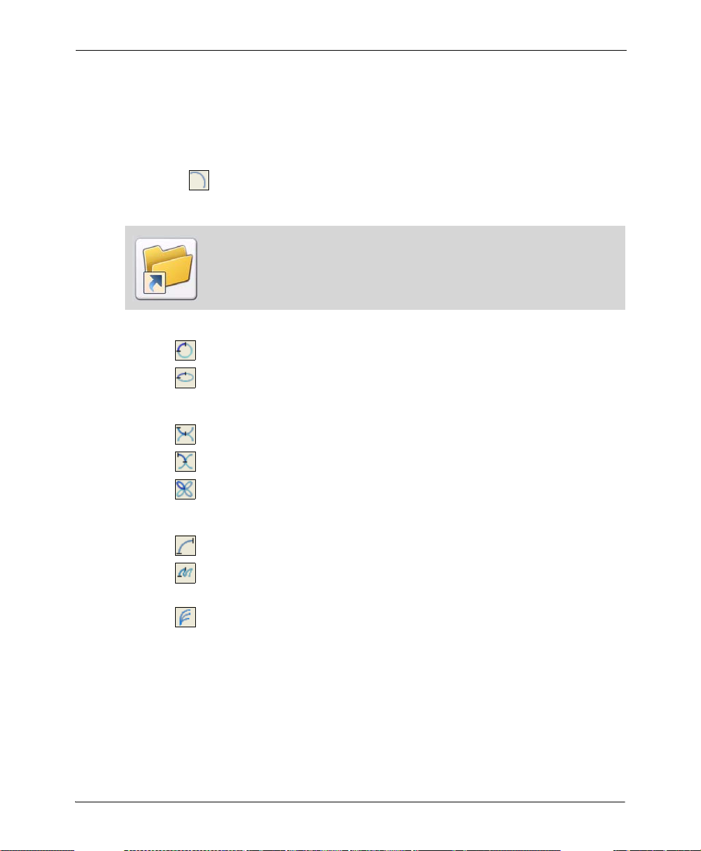
2 Select the curve type from the following:
uses circle sections to draw curves.
uses ellipse sections to draw curves.
3 Select the curve direction from the following:
draws a curve horizontally.
draws a curve vertically.
draws a curve in any direction.
4 Select the curve style from the following:
draws curves one at a time.
connects curves between successive mouse clicks until another curve option
or drawing tool is selected.
creates curves continuously from one point.
Chapter 4: Drawing Objects 69

5 Select the required curve thickness and style. For more information, see “Line Width
and Line Style” on page 82.
Curve style examples.
Drawing Polygons/Polylines
You can use the Polygon/Polyline tool to draw filled and unfilled polylines and polygons.
T o draw a polygon/polyline:
1 Click on the Drawing toolbar.
The Toolbox displays the associated options.
You can also draw a polygon/polyline by selecting Polygon/Po lyline from the
Tools menu.
2 Select either polygon or polyline from the following:
draws a polygon.
draws a polyline.
70 DesignPro Tools Graphics Editor® for Xerox User Guide

3 Select the required polygon/polyline direction from the following:
draws lines that snap to horizontal or vertical lines.
draws lines in any direction.
4 Select the required polygon fill mode option from the following:
fills areas accessible only from outside polygon by crossing odd number of
lines. This option is enabled only when and are selected.
fills the entire polygon with selected color or pattern. This option is enabled
only when and are selected.
Alternate polyline.
5 Select the polygon fill option form the following:
draws an empty polygon.
draws a polygon with the selected background.
draws a polygon with the pattern selected in the Select Pattern dialog. For
more information on selecting patterns, see “Working with Patterns” on page 83.
Polygon border uses the foreground color set in the Color bar.
Chapter 4: Drawing Objects 71

6 Select the required polygon/polyline thickness and style. For more information, see
“Line Width and Line Style” on page 82.
7 Click to apply settings.
Polygons and polylines style examples.
Filling Objects
Object fill colors are determined by foreground and background colors selected from the
Color bar. Patterns can also be used to fill objects; fill patterns are selected from the Select
Pattern dialog. Graphics Editor provides four tools for filling: color picker, brush,
airbrush and floodfill.
The object fill color matches the pattern selected from the Select Pattern dialog. Object
fill colors are determined by foreground and background colors selected from the Color
bar.
72 DesignPro Tools Graphics Editor® for Xerox User Guide

Using the Color Picker
You can use the Color Picker tool to copy any color from the image and use that color in
different drawing operations.
To copy a color from an existing image:
1 Click on the Drawing toolbar.
You can also copy a color from an existing image by selecting Color Picker from
the Tools menu.
2 Click the area containing the color you want to copy. The selected color is added to
the Color bar.
3 Use the specified color for any drawing operation.
Using Floodfill
You can use the Floodfill tool to fill an area or area bounded by current foreground color
with the selected background color or a pattern.
To fill an area with a selected color or a pattern:
1 Click on the Drawing toolbar.
The Toolbox displays the associated options.
You can also fill an area with a selected color or a pattern by selecting Floodfill
from the Tools menu.
2 Select the required filling from the following:
fills area bounded by current foreground color with current pattern or
background color.
fills area having current foreground color with current pattern or background
color.
Chapter 4: Drawing Objects 73
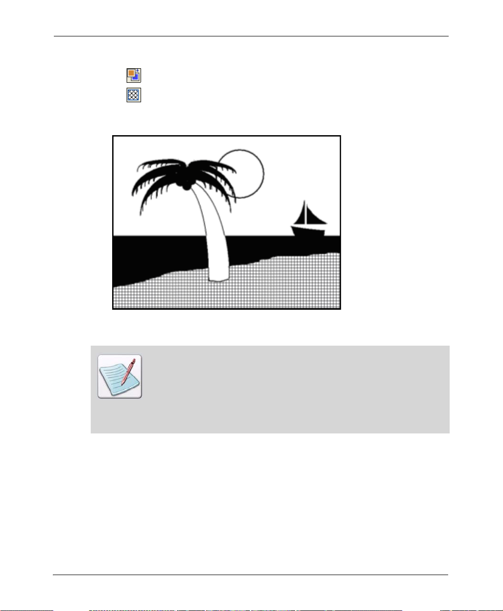
3 Select the floodfill type from the following:
fills area with the selected background color.
fills area with the selected pattern. For more information on selecting
patterns, see “Working with Patterns” on page 83.
Beach flood-filled with brick pattern example.
If an area is already filled, you can replace the fill with another pattern or color
only if the area is defined by a border color different from the fill color or
pattern. For example, if you have a shape with a color border and black and white
pattern fill, you can replace the black and white pattern with another black and
white pattern, solid black, or solid white. However, if the shape border is black or
white, you cannot replace the black and white pattern because the border color
is the same as the pattern color.
74 DesignPro Tools Graphics Editor® for Xerox User Guide
Using Airbrush
You can use the Airbrush tool to apply gradual tones to an image, simulating traditional
airbrush techniques. This tool "sprays" dots or patterns on an image.
To create an airbrush effect:
1 Click on the Drawing toolbar.
The Toolbox displays the associated options.
You can also create an airbrush effect by selecting Airbrush from the Tools
menu.
2 Select the spray type from the following:
sprays dots using the color selected from the Color bar.
sprays dots using the pattern selected from the Select Pattern dialog. For
more information on selecting patterns, see “Working with Patterns” on page 83.
3 Set the spray Area Width and Area Height.
4 Enter the required spray spot size in Spot Size entry box.
Chapter 4: Drawing Objects 75

5 Enter the spray spot border width in Spot Border entry box.
6 To spray, click and hold down the mouse button and drag the pointer.
You may want to experiment first with thin spray areas (for example, width 6, height 15 -
99). You can use this tool to create special effects. The figure below illustrates various
airbrush techniques.
Airbrush example.
76 DesignPro Tools Graphics Editor® for Xerox User Guide

Using Brush
You can use the Brush tool to paint continuous square or circular dots, or a series of
horizontal, vertical, or diagonal lines. Click and drag "brush tip" to create a shape. You can
paint using either the selected color or a pattern selected from the Select Pattern dialog.
To paint with a brush:
1 Click on the Drawing toolbar.
The Toolbox displays the associated options.
You can also paint with a brush by selecting Brush from the Tools menu.
2 Select the required brush tip from the following:
paints continuous square dots.
paints continuous circular dots.
Chapter 4: Drawing Objects 77
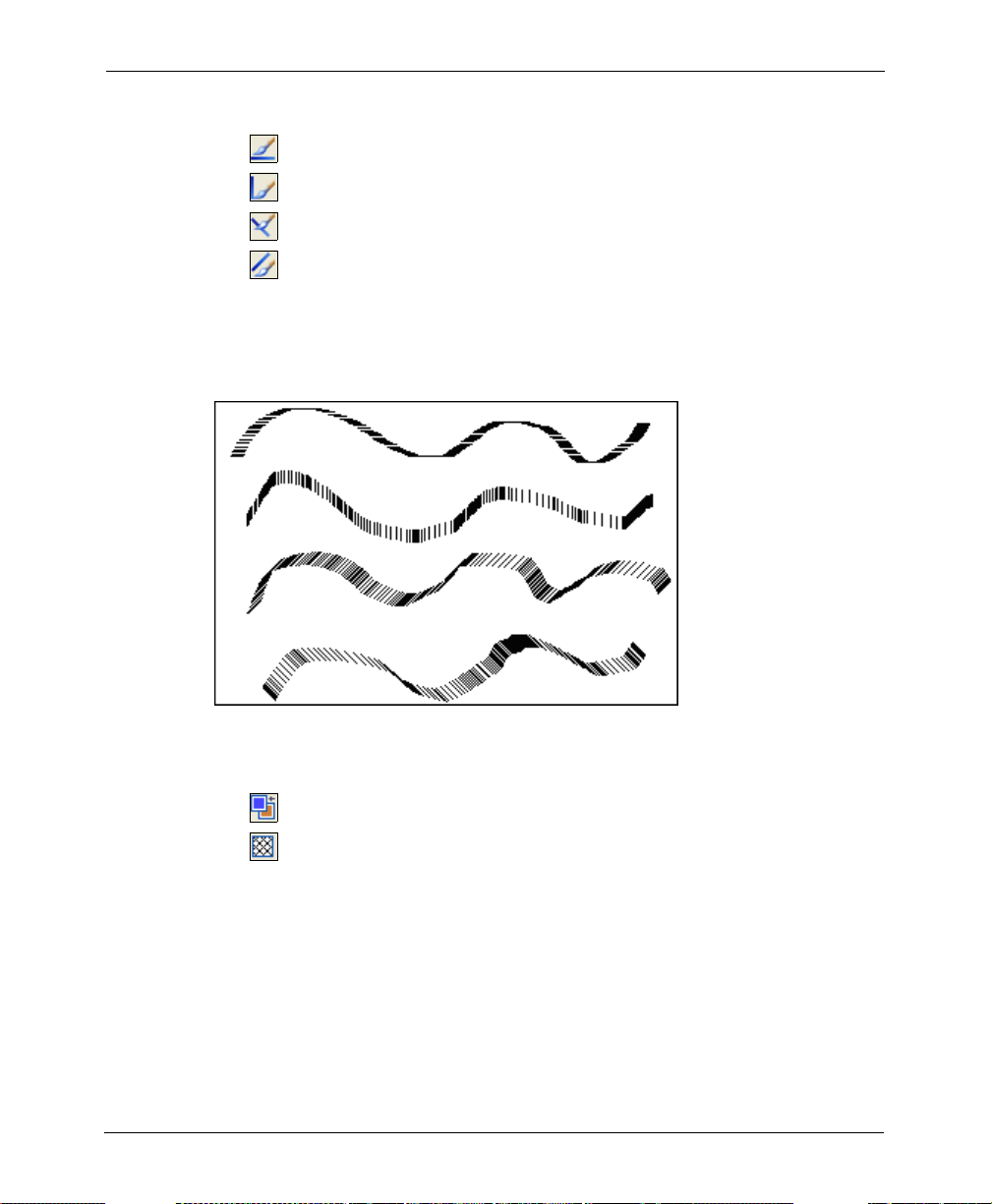
3 Select the brush stroke from the following:
paints series of continuous horizontal lines.
paints series of continuous vertical lines.
paints series of continuous diagonal lines to the right.
paints series of continuous diagonal lines to the left.
To achieve continuous painting action, draw slowly so that brush ti ps overl a p.
Figure below illustrates horizontal, vertical, diagonal right, and diagonal le ft brush
tips.
Samples of brush drawing.
4 Select the brush fill type from the following:
paints using the color selected from the Color bar.
paints using the pattern selected from the Select Pattern dialog. For more
information on selecting patterns, see “Working with Patterns” on page 83.
5 Select the required brush thickness. For more information, see “Line Width and Line
Style” on page 82.
78 DesignPro Tools Graphics Editor® for Xerox User Guide

Erasing Objects
Graphics Editor provides options for clearing image portions and replacing the erased
areas with the selected background color or a pattern. Erasing colors are determined by
foreground and background colors selected from the Color bar. Eraser patterns matches
the pattern selected from the Select Pattern dialog. Eraser thickness can also be set.
Using Eraser
You can use the Eraser tool to clear image portions.
To erase an image area:
1 Click on the Drawing toolbar.
The Toolbox displays the associated options.
The Shortcut symbol calls your attention to an easier way of accomplishing a
task.
2 Select the eraser type from the following options:
draws a rectangle in the Design Area to erase the required section and
replaces the erased section with the current background color. To erase an area,
press and hold left mouse button to start; as you move the mouse, the box
stretches and the area contained in the box erases.
draws individual squares in the Design Area to erase the required section and
replaces the erased section with the current background color. To erase an area
using this option, hold down the left mouse button; drag the mouse pointer and
the area covered by the square dots erases. Selecting this option activates the
eraser direction options; refer to the next step for more information.
3 Select the eraser direction from the following:
Eraser direction options are enabled only when is selected.
erases in horizontal direction only.
erases in vertical direction only.
erases in horizontal or vertical direction.
erases in any direction.
Chapter 4: Drawing Objects 79

4 Select the pixel replacement option from the following:
erases all image portions and replaces the erased portion with current
background color or pattern.
erases sections having current foreground color and replaces the erased
sections with the current background color or pattern.
5 Select the eraser fill type option from the following:
erases with current background color.
erases with current pattern or color.
6 Click on the Toolbox to select a pattern from the Select Pattern dialog. For
more information on selecting patterns, see “Working with Patterns” on page 83.
7 Select the required eraser thickness. For more information, see “Line Width and Line
Style” on page 82.
Enhancing Objects with Style Tools
Style tools are located in Toolbox and on the Drawing toolbar. Common style tools are:
Pattern and Preview Area (page 81)
Line Width and Line Style (page 82)
80 DesignPro Tools Graphics Editor® for Xerox User Guide

Pattern and Preview Area
The pattern feature is available in the Toolbox for almost all tools accessed from the
Drawing toolbar. The current pattern selection displays in the Preview Area. Refer to
“Working with Patterns” on page 83 for more information on selecting patt erns.
Right-clicking di splays the selected pattern in the Design Area. You can zoom in to
view the pattern more clearly, and make required changes. For more information, refer to
“Editing a Pattern” on page 84.
The image above displays the selected pattern magnified in the Design Area.
Chapter 4: Drawing Objects 81

Line Width and Line Style
Graphics Editor provides various options on the Drawing toolbar for setting the width and
style of the object boundaries. The line width and style features can be used not only to
specify the thickness and style of a line or a brush, but also the thickness and style of circle
curves. In addition, the line width option can be used to specify the eraser thickness.
To change the line width:
1 Click on the Drawing toolbar.
2 Select the appropriate width from the drop-down menu. To specify a customized
width, select Custom Width from the drop-down menu.
The Customize Line Width dialog displays.
3 Enter the required width in Line Width.
You can enter any value between 0 and 99 inclusive.
To draw an object without an outline, set Line Width 0.
T o change the line style, click on the Drawing toolbar and select the appropriate style
from the drop-down menu.
82 DesignPro Tools Graphics Editor® for Xerox User Guide

Working with Patterns
Graphics Editor provides different patterns to add visual interest to an image. Choose a
drawing tool and click in the Toolbox to use patterns in the current image. As you
draw in the Design Area, shapes assume the pattern shown in the Preview Area of the
Toolbox. Topics in this section include:
Selecting a Fill Pattern (page 83)
Editing a Pattern (page 84)
Selecting a Fill Pattern
The Select Pattern dialog features a number of predefined shading patterns to meet
different image design requirements. When creating a full color image, you can select
patterns based on the color palette in Highlight Color mode.
T o select a pattern:
1 Select the required drawing tool from the Drawing toolbar.
The Toolbox displays the associated options.
2 Click on the Toolbox.
3 Click to open the Select Pattern dialog.
Chapter 4: Drawing Objects 83

4 Select one of the following:
Black/White: uses black and white color mode. Selecting this option enables the
B/W Category drop-down list.
Highlight Color: uses highlight color mode. Selecting this option enables the
Pattern File drop-down list.
5 Choose the required pattern style from either the B/W Category (in the case of
Black/White) or Pattern File (in the case of Highlight Color).
6 Click on a specific pattern from the selection box.
7 Click OK to accept changes and return to the Design Area.
Editing a Pattern
You can modify the selected style of the pattern and the pattern file, change background
colors, and fill selections using the Edit Pattern dialog. Your selections display in the
Sample Area.
T o edit a pattern:
1 Select the required drawing tool from the Drawing toolbar.
The Toolbox displays the associated options.
2 Click on the Toolbox.
3 Right-click a color in the Color bar to choose a background color.
4 Click to open the Select Pattern dialog.
84 DesignPro Tools Graphics Editor® for Xerox User Guide

5 Select Highlight Color and click Edit Pattern to edit a pattern.
The Edit Pattern dialog displays.
6 Make the required changes.
Click on individual boxes to
apply the selected color
Select the required color
The image above explains how you can use the Edit Pattern dialog.
7 Enter the pattern name in the Ink Name entry box.
You can fill the entire pattern with a single color by clicking Fill Whole Area.
You can also remove all of the changes by clicking Undo All Changes.
8 Click OK to save settings and return to the Select Pattern dialog.
9 Click Save to save the edited pattern.
The Save As dialog displays.
10 Save the pattern and return to the Select Pattern dialog.
By default, the patterns are stored as Elixir font files.
11 Click OK to return to the Design Area.
Chapter 4: Drawing Objects 85

Drawing Modes
The drawing mode tools are located on the Drawing Modes toolbar. There are three
available drawing modes:
Overwriting: Opaque Mode (page 86)
Adding: Transparent Mode (page 87)
Reversing: Overlay Mode (page 87)
Selecting any mode from the toolbar activates that drawing mode.
Drawing modes are applicable to copy operations and all tools, except for .
The most recently applied drawing mode settings are used each time you open
Graphics Editor.
Overwriting: Opaque Mode
Selecting from the Drawing Modes toolbar draws or adds text over an image.
Opaque drawing mode example.
86 DesignPro Tools Graphics Editor® for Xerox User Guide

Adding: Transparent Mode
Selecting from the Drawing Modes toolbar draws or adds text over an im age by
replacing the area underneath, which causes the new drawing to merge with the existing
image.
Transparent drawing mode example.
Reversing: Overlay Mode
Selecting from the Drawing Modes toolbar draws and wri tes over an image by
inverting the color of the image area underneath the new drawing.
Reverse drawing mode example.
Chapter 4: Drawing Objects 87

88 DesignPro Tools Graphics Editor® for Xerox User Guide

Chapter 5:
Editing Images
In this chapter...
Editing Images
Image Change Commands
Zooming In and Out
Using Colors
About User Profiles
Image Format Properties
Elixir Parameter File (EPM)
Editing Images
You can modify images and image areas using basic editing commands, including cut,
copy , paste, and delete. You can select either an entire image or an image area to move,
copy , cut and paste. The edit commands provided can copy marked areas from one image,
and paste the copied selection to another location within the image. You can also apply
colors to images or change existing colors. Image editing involves the following
operations:
Using the Select Tool (page 90)
Selecting an Image (page 90)
Selecting an Image Area (page 91)
Copying an Image (page 91)
Cutting an Image (page 92)
Pasting an Image (page 93)
Moving an Image Area (page 94)
Copying and Pasting Screen Area (page 95)
Using the Save Selection Option (page 96)
89

Using the Select Tool
You can use the Select tool to define straight-edged marquee to move, cut, copy and paste
a rectangular image area.
1 Click on the Drawing toolbar.
2 Draw a marquee around the area that you want to select.
After selecting the required image or image area, you can either move, copy or cut the
image to paste to another location.
Selecting an Image
To select/outline an entire image, select Select All from the Edit menu. You can also
select an entire image using the Control + A shortcut key. You can cancel the image
selection by selecting Deselect from the Edit menu.
Selecting an entire image.
90 DesignPro Tools Graphics Editor® for Xerox User Guide

Selecting an Image Area
T o select an image area for editing, click on the Drawing toolbar. Draw a marquee
around the required image area. A dashed box displays around the selected image area.
You can cancel the image selection by selecting Deselect from the Edit menu.
Selecting an image area.
Copying an Image
Graphics Editor provides the copy feature to copy an image or image area. Copying an
image area places a copy of the image on the clipboard. You can paste a copy of the
selection in the same image or in a different image. However, attempting to paste an image
larger than the defined page size will result in partial pasting only; page size is not
dynamic and does not increase to accommodate images larger than the specified page size.
There are several methods for copying images/image areas.
To copy an image/image area:
1 Select the image/image area.
For information on selecting an image, refer to the task “Selecting an Image” on
page 90. For information on selecting an image area, refer to the task “Selecting an
Image Area” on page 91.
2 Do one of the following:
From the Edit menu, select Copy.
Click on the Standard toolbar.
Right-click the selected image/image area and select Copy from the pop-up
menu.
You can also copy an object using the Control + C shortcut key.
Chapter 5: Editing Images 91

Cutting an Image
Graphics Editor provides the cutting feature to cut an image/image area and paste it from
one location to another. Cutting an image area removes it from the image and places it on
the clipboard. You can then paste the image/image area in the same image or in a different
image. However, attempting to paste an image larger than the defined page size will result
in partial pasting only; page size is not dynamic and does not increase to accommodate
images larger than the specified page size. There are several methods for cutting images/
image areas.
To cut an image/image area:
1 Select the image/image area.
For information on selecting an image, refer to the task “Selecting an Image” on
page 90. For information on selectin g an image area, refer to the task “Selecting an
Image Area” on page 91.
2 Do one of the following:
From the Edit menu, select Cut.
Click from the Standard toolbar.
Right-click the selected image/image area and select Cut from the pop-up menu.
You can also cut an object using the Control + X shortcut key.
92 DesignPro Tools Graphics Editor® for Xerox User Guide

Pasting an Image
You can edit images by pasting selections cut or copied on the clipboard. However,
attempting to paste an image larger than the defined page size will result in partial pasting
only. Page size is not dynamic and does not increase to accommodate images larger than
the specified page size.
T o paste an image, do any of the following:
From the Edit menu, select Paste.
Click from the Standard toolbar.
Right-click in the Design Area and select Paste from the pop-up menu.
You can also paste an object using the Control + V shortcut key.
You can also paste an object using the Control + V shortcut key.
You can also paste images/image areas at a precise location using Paste Special options
provided by Graphics Editor. For information on using paste special options, refer to the
task “Using Paste Special Options” on page 93.
Using Paste Special Options
T o paste an image area in a specific image location, Graphics Editor provides paste special
options. To use these options, you need to specify the appropriate option from the Edit
menu and select the target area before pasting the image.
To paste an image area in a specific image location:
1 Copy or cut the required image/image area.
For information on copying an image/image area, refer to the task “Copying an
Image” on page 91. For information on cutting an image/image area, refer to the task
“Cutting an Image” on page 92.
2 From the Edit menu, select Paste Special, and then choose one of the following:
Not Clipped: pastes the image in the selected area at the actual size; if the image
is larger than the selected area, the image is extended beyond the selected area.
Clip to Area: pastes the image in the selected area; if the image is larger than the
selected area, only a partial image is displayed in the selected area.
Chapter 5: Editing Images 93

You can also press Control + Shift + V to use the Clip to Area option.
Fit to Area: pastes the image in the selected area; if the image is larger or smaller
than the copied image, the copied image either expands or contracts to fit in the
selected area.
You can also press Control + Alt + V to use the Fit to Area option.
3 Click and drag to draw another selection rectangle.
4 Select Paste from the Edit menu to paste the copied image to an existing or new
image.
Moving an Image Area
You can move an image or an image area to any other location in the Design Area. Select
and drag the required image/image area to the required location using the mouse pointer.
Release the mouse pointer to place the selected area in a new location.
For more information on selecting an image, refer to the task “Selecting an Image” on
page 90. For informatio n on s elect i n g an image area, refe r to the task “Se lecting an Ima ge
Area” on page 91.
94 DesignPro Tools Graphics Editor® for Xerox User Guide
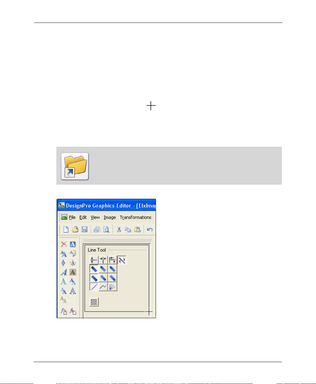
Copying and Pasting Screen Area
In addition to copying selected areas between images, you can copy a selected screen area
of Graphics Editor, Desktop or any other running applications, and paste them into the
current or a new image. You can also paste a screen area to the required image file and
location.
To copy the selected screen area:
1 From the Edit menu, select Copy Screen Area.
The mouse pointer changes to .
2 Click and drag the mouse pointer to select the required screen area, then release the
mouse pointer.
The selected area is copied.
Use the shortcut keys Control + V to paste the selected screen area to the
required location.
Copying a screen area.
Chapter 5: Editing Images 95

Using the Save Selection Option
You can save a selected image area to a separate image using the Save Selection option.
To save the selected portion of an image:
1 Click and draw a box around the area to be saved.
2 From the Edit menu, select Save Selection.
The Save As dialog displays.
3 Specify the directory to save the image in, and select the required file format from
the Save As drop-down list.
4 Click Save to save the new image.
Image Change Commands
Image transform commands in Graphics Editor help to enhance image presentation. These
commands include:
Merging an Image with another Image (page 97)
Changing Canvas Size (page 99)
Breaking up an Image (page 100)
Converting an Image to a Form Template (page 102)
96 DesignPro Tools Graphics Editor® for Xerox User Guide
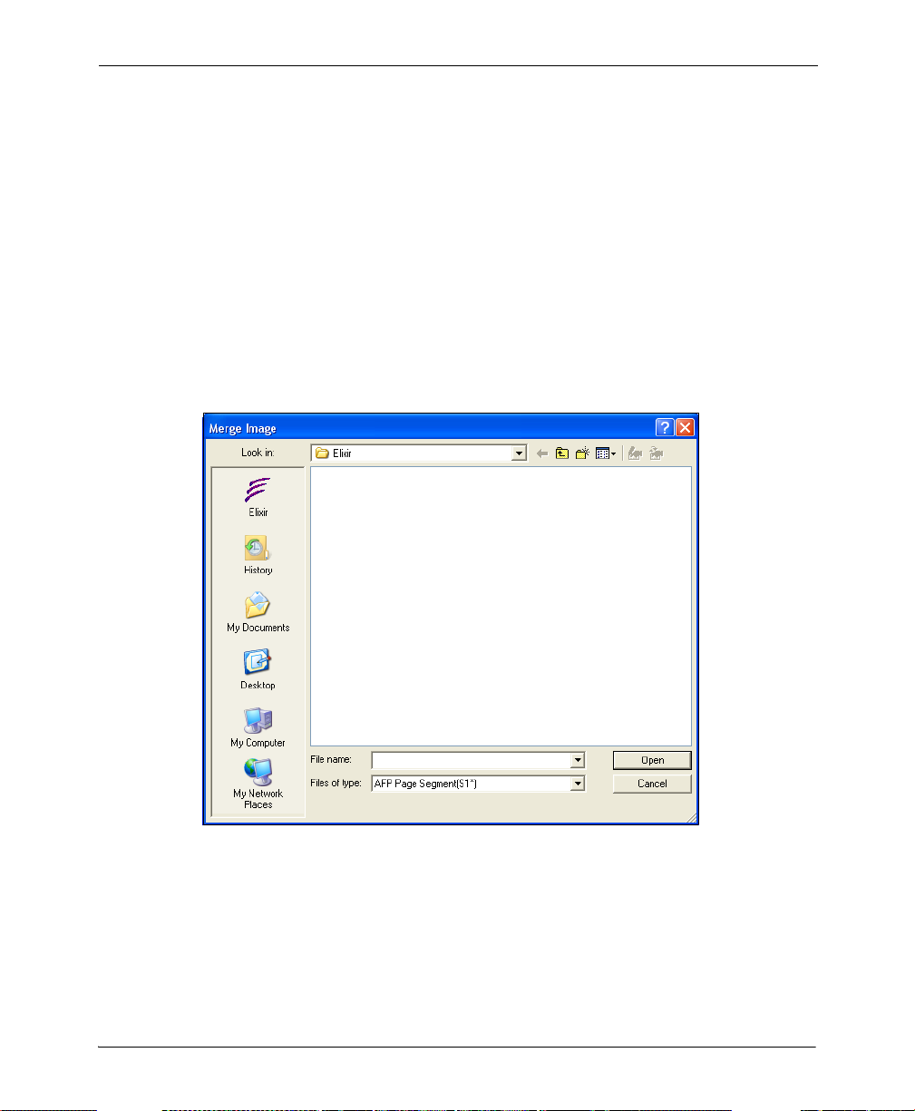
Merging an Image with another Image
You can open an image and merge it with the current image. Before merging images, you
need to select the appropriate Paste Special option from the Edit menu.
To merge the currently open image with another image:
1 Select the required Paste Special option from the Edit menu.
For more information on using paste special options, refer to the task “Using Paste
Special Options” on page 93.
2 Select the image or an image area.
3 From the Image menu, select Merge.
The Merge Image dialog displays.
Chapter 5: Editing Images 97

You can also use the Control + M shortcut key to open the Merge Image
dialog.
4 Select the required image and click Open.
The selected image merges depending on the paste special option selected.
(1) Image area with Fit to Area (Paste Special) option selected (2) Merged image in
the selected area.
Merging of the images also depends on the drawing modes. For more information
on drawing modes, see “Drawing Modes” on page 86 in Chapter 4: “Drawing
Objects” on page 59.
98 DesignPro Tools Graphics Editor® for Xerox User Guide

Changing Canvas Size
Graphics Editor provides the image contract and expand features to modify the width or
height of an image; this is done by either cropping the image or adding a blank canvas to
the image.
To contract an image:
1 From the Image menu, select Expand/Contract.
The Expand/Contract Image dialog displays.
You can also open the Expand/Contract dialog using Control + E shortcut
key.
2 Enter a value in the following entry boxes:
Left: crops/expands the image from the left.
Right: crops/expands the image from the right.
Top: crops/expands the image from the top.
Bottom: crops/expands the image from the bottom.
To reduce image size, enter a negative value. Similarly, to increase image size,
enter a positive value.
3 Click OK to return to the Design Area.
The image size changes as specified.
Chapter 5: Editing Images 99

Breaking up an Image
To break up an image into horizontal or vertical strips of equal height and width:
1 From the Image menu, select Split.
The Break Up Image dialog displays.
You can also use the Control + L shortcut key to open the Break Up
Image dialog.
2 Select the required break up sequence option from the following:
Pieces in Horizontal Direction: breaks the image into the specified number of
horizontal image pieces.
Pieces in Vertical Direction: breaks the image into the specified number of
vertical image pieces.
100 DesignPro Tools Graphics Editor® for Xerox User Guide
 Loading...