

Page 1
P H A S E R S H A R E
Manual
®
N E T W O R K I N G
www.tek.com/Color_Printers/
®
Page 2

Page 3

PhaserShare
®
Networking Manual
V3 April 1999
071-0180-01
Page 4

x
x
*
*
Copyright
©
Tektronix, Inc.
Unpublished rights reserved under the copyright laws of the United States. Contents of this publication may not be reproduced in
any form without permission of Tektronix, Inc.
Tektronix
®
, Phaser
®
, PhaserShare
®
, the TekColor logo, ColorStix
®
, ColorCoat
®
, and Made For Each Other
®
are registered
trademarks of Tektronix, Inc. Finepoint™, PhaserLink™, PhaserPrint™, the TekColor name, and PhaserSym™ are trademarks of
Tektronix, Inc.
Adobe
Apple
®
and PostScript
®
, AppleTalk
®
are trademarks of Adobe Systems Incorporated which may be registered in certain jurisdictions.
®
, LocalTalk
®
, EtherTalk
®
, TokenTalk
®
, and Macintosh
®
are registered trademarks of Apple Computer, Inc.
SGI™ is a trademark of Silicon Graphics, Inc.
®
SPARC
is a registered trademark of SPARC International, Incorporated. SPARCstation™ is a trademark of SPARC International,
Inc., licensed exclusively to Sun Microsystems, Inc.
Tektronix Phaser 840, Phaser 740, Phaser 780, and Phaser 360 printers are certified as NetWare print server
devices, on both 3.12 and 4.1
NetWare systems. NetWare NDS is certified on 4.1
NetWare systems. Bindery mode is also certified to comply on both 3.12 and 4.1 x
NetWare systems.
Novell® and NetWare® are registered trademarks of Novell, Inc.
®
is a registered trademark in the United States and other countries, licensed exclusively through X/Open
UNIX
Company, Ltd.
Times™, Helvetica™ and Palatino™ are trademarks of Linotype-Hell AG and/or its subsidiaries.
Other marks are trademarks or registered trademarks of the companies with which they are associated.
®
PANTONE
Colors generated by Phaser Color Printers are four- and/or three-color process simulations and
may not match PANTONE-identified solid color standards. Use current PANTONE Color Reference Manuals
for accurate colors.
PANTONE Color simulations are only obtainable on these products when driven by qualified Pantone-licensed software
packages. Contact Pantone, Inc. for a current list of qualified licensees.
Pantone, Inc.’s check-standard trademark for color reproduction and color reproduction materials.
© Pantone, Inc., 1988.
Page 5

Contents
1 Network Printing with Tektronix Color Printers
Key components for networking Tektronix color printers 1
Network installation overview 6
The printer’s Configuration Page 6
How to tell which protocols are enabled 8
The printer’s networking software 8
Support for DOS systems 10
Tektronix PhaserPrint for UNIX software 10
2 PhaserShare Series B Network Interfaces
PhaserShare Series B Ethernet interface 11
PhaserShare Series B Token Ring card 14
PhaserShare Series B LocalTalk card 22
3 EtherTalk, LocalTalk, and TokenTalk Configuration
Before you begin 25
Configuration overview 25
Finding the printer’s name in the Chooser 26
Changing the printer’s name (optional) 27
Changing the printer’s EtherTalk/TokenTalk zone (optional) 29
Troubleshooting 30
4 Novell NetWare Configuration
The printer’s NetWare interface 31
Before beginning the configuration procedure 32
Configuration software for NetWare 33
NetWare configuration for Windows environments 33
Troubleshooting Windows configurations 36
Setting IPX frame types from the front panel 40
5 PhaserShare Administrator Software for NetWare Networks
Introduction to the PhaserShare Administrator 43
NetWare configuration with the PhaserShare Administrator 44
Installation 44
Using the PhaserShare Administrator 46
PhaserShare Administrator on-line help 50
6 TCP/IP Configuration Overview
Before you begin 52
Extracting files from unix.tar 52
Printing the Configuration Page 52
TCP/IP configuration overview 53
PhaserShare Networking Manual
iii
Page 6

7 TCP/IP Printer Configuration (All Platforms)
Setting the printer’s IP addressing parameters 55
General information on setting IP parameters (front panel) 57
Setting IP parameters: Phaser 840 printer front panel 57
Setting IP parameters: Phaser 740 printer front panel 58
Setting IP parameters: Phaser 780 printer front panel 60
Setting IP parameters: Phaser 360 printer front panel 63
Setting IP parameters: RARP or BOOTP 65
Setting IP parameters: DHCP 66
Supported BOOTP/DHCP fields 68
Enabling and disabling RARP and BOOTP/DHCP (front panel) 69
Setting IP parameters: PhaserLink Printer Management Software 73
Controlling host access 76
Receiving printer status 79
8 TCP/IP Host Configuration (UNIX)
Configuring a host 83
Troubleshooting 94
9 TCP/IP Configuration (OS/2 Warp/LAN Server)
Setting the printer’s IP addressing parameters 95
Creating an LPR queue in OS/2 Warp Connect (direct LPR connection to the printer) 96
OS/2 client-to-server setup 97
Warp Server 4.0/Warp Connect 98
10 Windows NT
Setting the printer’s IP address 99
Adding the Windows NT 4.0 driver on a Windows NT 4.0 server or workstation 99
Adding the Windows NT 4.0 driver on a
Windows NT 3.51 server 104
Adding a Windows NT 3.x driver 109
Windows NT network communication 112
Windows NT network troubleshooting 113
11 Windows 95 and Windows 98: PhaserPort Software
TCP/IP configuration for the PC 117
Setting the printer’s IP address 117
PhaserPort software installation 118
Adding a port for a new printer 119
Adding a port to an existing printer 119
Changing a port’s IP address 120
iv
PhaserShare Networking Manual
Page 7

12 PhaserLink Printer Management Software
System requirements 121
Multiple language support 121
Accessing printer information from a browser 122
Printer information pages 122
Printer status display 124
PhaserLink Printer Management Software help files 125
Setting printer parameters: PhaserLink Printer Management Software pages 126
Information Forwarding 126
13 Printer Management
Job accounting 127
PhaserLink PDF Direct Printing 128
Phaser 840 Intelligent Ready 129
PhaserLink Status Notification (Email Notification) 130
Usage Profile reports (Phaser 840, 740 and 780 printers only) 131
Printing Usage Profile reports from the front panel 132
Printing verbose Usage Profile reports from the front panel 133
Printing Usage Profile reports from PhaserLink Printer Management Software 134
Sending Usage Profile reports via email from the front panel 134
Sending Usage Profile reports via email: PhaserLink Printer Management Software 136
Controlling Usage Profile email reporting 137
Email to Tektronix 138
Reading Usage Profile reports 139
Report fields 140
Logs 145
14 Getting Help
If you need help from Tektronix 153
Using the automated fax systems 155
Receiving email update notices 156
15 Disabling Protocols
Disabling protocols: front panel 158
If the front panel is locked 165
Disabling protocols: PhaserShare Administrator 166
Disabling protocols: PhaserLink Printer Management Software 166
PhaserShare Networking Manual
v
Page 8

16 Resetting the Printer
Resetting the printer: PhaserLink Printer Management Software 167
Resetting your printer using the Apple Printer Utility 168
17 FTP Interface
Index
vi
PhaserShare Networking Manual
Page 9

Chapter
1
Network Printing with Tektronix Color Printers
This manual provides information for system administrators and others who need to
install Tektronix Phaser 840, Phaser 740, Phaser 780, and Phaser 360 printers
equipped with PhaserShare Series B network interfaces.
■
Before using this manual, unpack and set up your printer. Install the
appropriate drivers on any PC and Macintosh computers on your network.
Instructions for unpacking, set-up, and installation are contained in your
printer’s user documentation.
■
After your printer is set up, use this manual in conjunction with your printer’s
PhaserShare Administrator or PhaserLink Printer Management Software to
configure the printer on the network.
This manual covers the following hardware and software versions:
■
PhaserShare Series B interfaces
■
PhaserShare Administrator version 3.9
Key components for networking Tektronix color printers
The following items are key components for networking your Tektronix printer:
■
PhaserShare Series B network interface. This brings ease-of-use, superb
shareability and broad compatibility to Tektronix Phaser color printers. For
more information, see “PhaserShare Series B network interface” on page 2.
■
PhaserShare Administrator software. PhaserShare Administrator
software makes it easy to install, configure, and manage Phaser printers on
a NetWare network. For more information, see Chapter 5, “PhaserShare
Administrator Software for NetWare Networks”.
PhaserLink Printer Management Software. PhaserLink Printer
■
Management Software is internal printer software that provides printer
status and supports printer management through a World Wide Web
browser. For more information, see Chapter 12, “PhaserLink Printer
Management Software”.
PhaserPrint for UNIX software. PhaserPrint for UNIX software provides a
■
driver with push-button control of printer features and fast raster file
printing capability from UNIX workstations. For more information, see
“Tektronix PhaserPrint for UNIX software” on page 10.
PhaserShare Networking Manual
1
Page 10

Network Printing with Tektronix Color Printers
1
PhaserShare Series B network interface
The Phaser 840, 740, 780, and 360 printers support the PhaserShare Series B network
interface. These printers are equipped with a built-in PhaserShare Series B network
interface with a 10BaseT Ethernet connector. This printer can be equipped with
these optional PhaserShare Series B network cards:
■
PhaserShare Series B Fast Ethernet card. This card is equipped with a
combined 10BaseT and 100BaseTx connector and a 10Base2 (BNC)
connector. The combined 10BaseT/100BaseTx connector can be connected
to either a 10BaseT or 100BaseTx network, and it will automatically adjust
to the correct data rate using a process called auto-negotiation . If no
connection is made to the 10BaseT/100BaseTx connector, the card is
prepared to communicate using the 10Base2 connector.
PhaserShare Series B Token Ring card. This card is equipped with STP
■
(Shielded Twisted Pair) and UTP (Unshielded Twisted Pair) connectors.
Only one connector at a time can be used.
PhaserShare cards
PhaserShare Series B LocalTalk card (AppleTalk).
■
PhaserShare network cards can be purchased initially with the printer as options or
added later as upgrade kits. A printer can have only one card at a time installed.
When a PhaserShare Series B Fast Ethernet or Token Ring card is installed, the
standard 10BaseT connector on the printer’s rear panel is disabled. The card and
the printer’s standard parallel port can be simultaneously active. All network
protocols can be simultaneously active.
PhaserShare cards work with the following printers: Phaser 380, 350, 340, 560, 550,
540, and 600. PhaserShare cards enable you to use your printer with Ethernet, Token
Ring, LocalTalk, or serial connections. PhaserShare cards can be purchased initially
with the printer as options or added later as upgrade kits.
A printer can have only one PhaserShare card installed at a time. When a
PhaserShare card is installed, all ports on the card and the printer’s standard parallel
port can be simultaneously active. Also, all network protocols can be
simultaneously active.
For information on networking printers with PhaserShare cards, refer to the
PhaserShare Networking System Administrator Manual , part number 070-9789-00.
2
PhaserShare Networking Manual
Page 11

Network Printing with Tektronix Color Printers
Recognizing PhaserShare Series B interfaces and earlier PhaserShare cards
On your network, you may have some Tektronix printers equipped with
PhaserShare Series B interfaces and other Tektronix printers equipped with earlier
PhaserShare cards. Printers equipped with earlier PhaserShare cards are supported
differently in printer management software such as the PhaserShare Administrator
and PhaserLink Printer Management Software. There are several ways to determine
if the printer is equipped with a PhaserShare Series B interface or an earlier
PhaserShare card:
Printer model. PhaserShare Series B cards work with Phaser 840, 740, 780,
■
and 360 printers. PhaserShare cards work with the following printers:
Phaser 380, 350, 340, 560, 550, 540, and 600.
Card rear panel. The cards are labeled on the rear panel.
■
The printer’s Configuration Page. For Series B interfaces, Series B
■
appears following the Network Information area on the printer’s
Configuration Page. If an earlier PhaserShare card is installed, the printer’s
Configuration Page reports the type of card installed in the PhaserShare
field.
1
The printer’s Startup Page. For Series B interfaces, Series B appears in the
■
Ethernet , Token Ring , or LocalTalk fields on the printer’s Startup Page. If
a PhaserShare card is installed, the printer’s Startup Page reports the
available connections in the Ports field.
PhaserLink Printer Management Software. If the Adobe PostScript field
■
reads Adobe PostScript Level 3 Version , the interface is Series B. If the
field reads Adobe PostScript Level 2 Version , the printer supports
PhaserShare network cards (not Series B). The Adobe PostScript field is on
the View Printer Information page or on the View and Configure General
Settings page, depending on the printer type. Links to these pages can be
accessed by clicking the Configuration link. For more information on
PhaserLink Printer Management Software, see Chapter 12, “PhaserLink
Printer Management Software”.
PhaserShare Administrator. In the PhaserShare Administrator, Series B
■
interfaces are identified in the Ethernet or Token Ring tabs, where Series B
is displayed in the Interface Information area. For more information on
the PhaserShare Administrator, see Chapter 5, “PhaserShare Administrator
Software for NetWare Networks”.
PhaserShare Networking Manual
3
Page 12

Network Printing with Tektronix Color Printers
1
Environments supported
Tektronix Phaser printers are compatible with mixed PC, Macintosh, and UNIX
environments. The printer automatically switches between the printer’s ports and
network protocols to service all computers on the network.
Phaser printers are compatible with nearly all PC client/server environments. The
printer’s Ethernet and Token Ring network interfaces are compatible with the
following:
NetWare servers via the IPX (Internet Packet Exchange) protocol
■
Windows NT servers over TCP/IP or EtherTalk protocols
■
LANServer 4.0 servers via TCP/IP
■
UNIX workstation via TCP/IP
■
Macintosh computers via AppleTalk (LocalTalk, EtherTalk and TokenTalk).
■
Windows 98
■
Windows 95
■
Supported PC platforms
Any PC in the server environments listed in the previous topic, “Environments
supported,” can print over the network to a Phaser printer, including the following:
Windows 98
■
Windows 95
■
Windows 3.1
■
Windows NT
■
Windows for Workgroups
■
OS/2 Warp
■
■ DOS
4
PhaserShare Networking Manual
Page 13
Network Printing with Tektronix Color Printers
Phaser printers are compatible with Banyan Vines and Microsoft LAN Manager
servers; however, third-party interfaces are required. Contact Tektronix Technical
Support for more information (see Chapter 14, “Getting Help”).
1
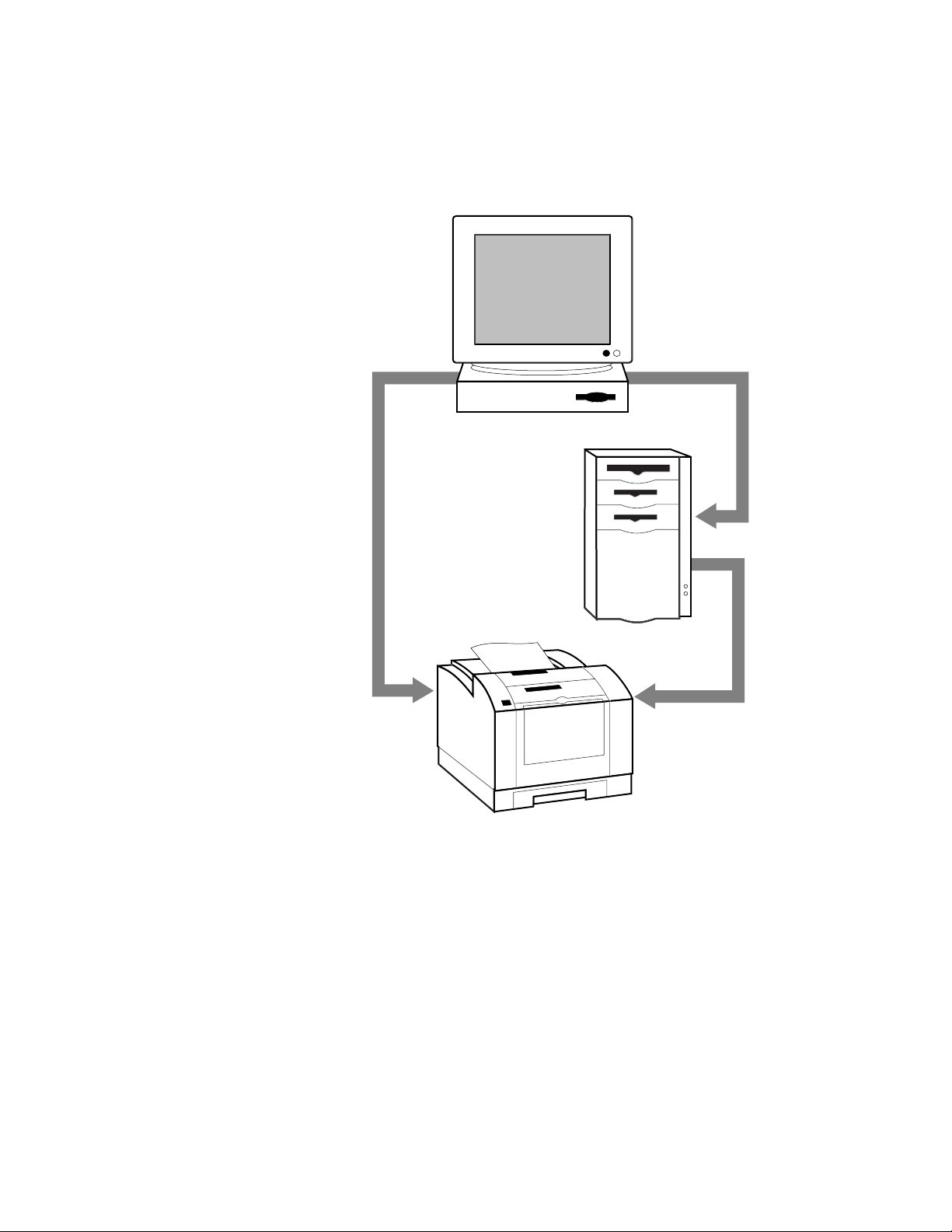
Workstations
UNIX
Macintosh
Windows 95
(peer - to - peer)
Clients
Windows 95
Windows 3.1
Windows NT
Windows for Workgroups
OS/2 Warp
DOS
Server
Novell NetWare (IPX)
Windows NT (EtherTalk
or TCP/IP)
LAN Server 4.0 (TCIP/IP)
UNIX (TCP/IP)
Phaser Color Printer
With PhaserShare
Ethernet or Token Ring
interface
9538-04c
PhaserShare Networking Manual
5
Page 14

1
Network Printing with Tektronix Color Printers
Network installation overview
Step 1 Unpack and set up
the printer.
Step 2 Install the network
card in the printer.
Step 3 Network
configuration.
This step must be done before attempting to configure the printer on a network.
Printer setup includes installing ink or toner, loading paper tra ys , and turning on
the printer. See your printer’s user documentation for information about printer
setup.
This step is necessary if the printer is to be equipped with an optional network
card. It is not necessary when using the printer’s built-in Ethernet connector.
This step is done at the factory when a network card is purchased initially with
your printer.
When a network card is purchased later as an upgrade kit, follow the
installation instructions included with the card.
Information on physically connecting the printer to networks is provided in this
manual:
For Ethernet, see “PhaserShare Series B Ethernet interface” on page 11.
For Token Ring, see “PhaserShare Series B Token Ring card” on page 14.
For LocalTalk, see “PhaserShare Series B LocalTalk card” on page 22.
For LocalTalk, EtherTalk, or TokenTalk, see Chapter 3, “EtherTalk, LocalTalk,
and T ok enTalk Configuration”.
For NetWare, see Chapter 4, “Novell NetWare Configuration”.
For TCP/IP, see:
Chapter 6, “TCP/IP Configuration Overview”.
Chapter 7, “TCP/IP Printer Configuration (All Platforms)”.
Chapter 8, “TCP/IP Host Configuration (UNIX)”.
Chapter 9, “TCP/IP Configuration (OS/2 Warp/LAN Server)”
Chapter 11, “Windows 95 and Windows 98: PhaserPort Software”.
For Windows NT, see Chapter 10, “Windows NT”.
The printer’s Configuration Page
Your printer can generate a Configuration Page that lists the following information:
■ General printer information, including TekColor settings
■ Communication and network parameters for all ports
■ SCSI disk settings (if the printer has a SCSI port)
The information supplied on the Configuration Page is helpful when you are
installing and configuring the printer on a network. There are two ways to print the
Configuration Page:
■ Use the printer’s front panel. You can easily print the Configuration Page
from the printer’s front panel. Use this method if your printer is not yet
configured on the network. Refer to:
■ “Printing a Configuration Page: Phaser 840 front panel” on page 7.
■ “Printing a Configuration Page: Phaser 740 and 360 front panels” on
page 7.
■ “Printing a Configuration Page: Phaser 780 front panel” on page 7.
■ Use PhaserLink Printer Management Software. With a TCP/IP
connection and a World Wide Web browser, you can use PhaserLink
Printer Management Software; see “Printing a Configuration Page:
PhaserLink Printer Management Software” on page 7.
6
PhaserShare Networking Manual
Page 15

Network Printing with Tektronix Color Printers
Printing a Configuration Page: Phaser 840 front panel
1.
When the front panel displays READY TO PRINT, press the down-arrow
button until Menu is highlighted. Press Select.
2.
Press the down-arrow button until Printer Configuration is
highlighted. Press Select.
3.
Press the down-arrow button until Print Configuration Page is
highlighted. Press Select.
Printing a Configuration Page: Phaser 740 and 360 front panels
1.
While Ready is displayed, press Menu; the printer displays the first item
in the menu:
Help Pages
<---- ----> Menu
2.
Press Menu to access the Help Pages; the following message appears:
Menu Map
<---- ----> Print
1
3.
Press <---- or ----> until the following message appears:
Configuration Page
<---- ----> Print
4.
Press Print.
Printing a Configuration Page: Phaser 780 front panel
1.
While Ready is displayed, press Select; the Printer menu is
displayed:
Printer Menu
Help Pages Menu
2.
Press Menu; the Help Pages menu is displayed:
Help Pages
Configuration Page Print
3.
Press Print.
Printing a Configuration Page: PhaserLink Printer Management Software
1.
From the printer’s home page, click Configuration; this displays the View
and Configure Settings page.
2.
On the View and Configure Settings page, select Configuration Page
from the pull-down list. Click Print.
For more information on PhaserLink Printer Management Software, see Chapter 12,
“PhaserLink Printer Management Software”.
PhaserShare Networking Manual
7
Page 16

1
Network Printing with Tektronix Color Printers
How to tell which protocols are enabled
All protocols can be enabled and disabled. The Configuration Page reports which
protocols are enabled. If a protocol is enabled, the field for that protocol lists the
current parameters. If the protocol is disabled, the field for that protocol contains an
entry reading Disabled.
The printer’s networking software
The printer is shipped with a software CD-ROM, which contains software that you
may need to install your printer on a network. The CD-ROM also contains on-line
documentation, printer drivers, and other printer software. A single integrated
installer is used to install printer drivers and other software.
Obtaining networking software for Phaser 840, 740, and 780 printers
You obtain the networking software from the CD-ROM by running the installer:
1.
Insert the printer’s software CD-ROM into the CD-ROM drive.
■ If the Windows autorun feature is enabled, the CD-ROM launches
automatically.
■ If the Windows autorun feature is disabled, double-click My
Computer, then double click the CD icon to launch the CD-ROM.
2.
View the brief introductory information, then click Install Drivers to
launch the installer.
3.
When you are prompted to select Easy Install or Custom Install, select
Custom Install.
4.
In the Custom Install dialog box, check the box for Network Utilities.
5.
If you are running the installer on a computer that has NetWare software
installed, you can also check the boxes to install the PhaserShare
Administrator software. For more information on the PhaserShare
Administrator software, see Chapter 5, “PhaserShare Administrator
Software for NetWare Networks”.
6.
To complete the installation, follow the on-screen prompts.
8
PhaserShare Networking Manual
Page 17

Network Printing with Tektronix Color Printers
Obtaining networking software for Phaser 360 printers
You obtain the networking software from the CD-ROM by running the installer:
1.
Locate and run the installer on the printer’s CD-ROM. On a PC, the file is
SETUP.EXE; on a Macintosh, it is Phaser 360 Installer.
2.
When you are prompted to select Easy Install or Custom Install,
select Custom Install.
3.
In the Custom Install dialog box, check the box for Network Utilities.
4.
If you are running the installer on a computer that has NetWare software
installed, you can also check the boxes to install the PhaserShare
Administrator software. For more information on the PhaserShare
Administrator software, see Chapter 5, “PhaserShare Administrator
Software for NetWare Networks”.
5.
To complete the installation, follow the on-screen prompts.
Network administration software
1
The following table lists the network administration software according to
environment (network protocol, platform, and printer).
Network administration software
Environment Software
NetWare; Windows 95,
Windows NT, and
Windows 3.1
TCP/IP; Windows 95 and
Windows 3.1
TCP/IP; Windows NT Printer configuration: PhaserLink Printer Management Software (PhaserLink
AppleTalk; Macintosh 7.x
and 8.x
TCP/IP; UNIX Printer configuration: PhaserLink Printer Management Software (If using
Network queue configuration: PhaserShare Administrator (Novell PCONSOLE
and NWAdmin can also be used.)
Printer configuration: PhaserShare Administrator (Over TCP/IP, PhaserLink
Printer Management Software can also be used; Novell’s PCONSOLE and
NWAdmin cannot configure the PhaserShare network interface.)
Printer status monitoring: Windows Print Monitor (over TCP/IP, PhaserLink
Printer Management Software can also be used; PhaserLink Printer Management
Software provides status on additional Tektronix printer features.)
Printer configuration: PhaserLink Printer Management Software
Printer status monitoring: PhaserLink Printer Management Software
Printer Management Software does not set up queues on the print server.)
Printer status monitoring: PhaserLink Printer Management Software
Printer configuration: PhaserLink Printer Management Software (MacTCP or
Open T r ansport required)
Printer status monitoring: PhaserLink Printer Management Software (MacTCP
or Open Transport required)
PhaserPrint for UNIX for printing, use PhaserPrint to set up print queues.)
Printer status monitoring: PhaserLink Printer Management Software
PhaserShare Networking Manual
9
Page 18

1
Network Printing with Tektronix Color Printers
Support for DOS systems
For information on installing Tektronix printers in DOS environments, see the
printer’s CD-ROM. They contain PostScript utility files that can be sent to the
printer for network configuration in DOS environments. They also contain a DOS
application, NWSET, for printer configuration on NetWare networks.
For information on how to use the DOS configuration files, see the README files on
the printer’s CD-ROM. PC users will find the README file for the PostScript utility
files in the UTILS directory; the README file for NWSET is in the NETWARE
directory. (Macintosh users will find the ReadMe file for the PostScript utility files in
the Network Utilities folder).
Tektronix PhaserPrint for UNIX software
For UNIX environments, Tektronix offers PhaserPrint software. PhaserPrint for
UNIX provides fast raster screen copy printing to Tektronix color printers.
PhaserPrint for UNIX also provides a graphical user interface for push-button
control of Tektronix printer features.
PhaserPrint for UNIX is available for these workstations:
■ Sun: SunOS 4.1.4, Solaris 2.3 and 2.4
■ SGI: IRIX 5.2, 5.3, 6.2, 6.3, and 6.4
■ HP 9000 700/800: HP-UX 9.0.5 and 10.2
■ IBM RS/6000: AIX 3.2 and 4.2
■ DECstation: ULTRIX 4.0 and 4.4
■ DEC Alpha AXP: OSF/1 3.0, 3.2, and Digital UNIX 4.0
PhaserPrint for UNIX works with the workstation’s native spooling system to print
PostScript files and raster files in these formats: Sun Raster Format (SRF), xwd, SGI
RGB, HP Starbase, TIFF, PBM, GIF, PCX, and BMP.
Your printer’s CD-ROM contains a demonstration copy of PhaserPrint for UNIX and
an on-line instruction guide in the unix/unixdemo directory. You can also obtain a
demonstration copy at this Tektronix site:
ftp.tek.com/cpid/UNIX/phaserprint2.1/demo
10
PhaserShare Networking Manual
Page 19

Chapter
2
PhaserShare Series B Network Interfaces
PhaserShare Series B network cards work with the Phaser 840, 740, 780, and 360
printers. Printers that work with PhaserShare Series B network cards have a built-in
PhaserShare Series B Ethernet interface on the rear panel. Earlier printers
(Phaser 380, 350, 340, 560, 550, 540, and 600) may be equipped with earlier
PhaserShare network cards; these printers have no built-in network connections on
the rear panel. If you are not sure which network interface your printer has, see
“Recognizing PhaserShare Series B interfaces and earlier PhaserShare cards” on
page 3.
This chapter provides information on connecting PhaserShare Series B interfaces to
the network; for information on installing PhaserShare Series B network cards, see
the instruction sheet that is shipped with each card.
PhaserShare Series B Ethernet interface
Ethernet is a communication standard that supports very high speed data
transmission. Ethernet offers significant speed improvement compared to serial,
parallel, and LocalTalk connections. Speed improvement varies greatly depending
on network traffic, computer hardware, and other factors.
The PhaserShare Series B Ethernet interface conforms to the IEEE 802.3 and Ethernet
II standards. With the printer’s built-in Ethernet interface, you can connect the
printer directly to an Ethernet network using twisted pair (10BaseT) cables. With the
PhaserShare Series B Ethernet card, you can connect the printer directly to an
Ethernet network using twisted pair (10BaseT or 100BaseTx) or thin coax (10Base2)
cables. Connecting the printer using thick coax (10Base5) requires an adapter;
contact your dealer to obtain adapters, cables, and terminators.
When a PhaserShare Series B Ethernet card is installed, the built-in Ethernet
connector is disabled; use the connectors on the card.
When a PhaserShare Series B card is purchased initially with the printer, it is
installed at the factory. When a PhaserShare Series B card is purchased later as an
upgrade kit, follow the instructions that are shipped with the card.
C A U T I O
N
To avoid damaging the network interface, turn off the printer before making any
Ethernet connections.
PhaserShare Networking Manual
11
Page 20
2
9789-05
13 5 6
24
100
Mbs
10/100Base-TX
10Base2
TP
LINK
TX
RX
PhaserShare
TM
Series B
Ethernet Card
PhaserShare Series B Network Interfaces
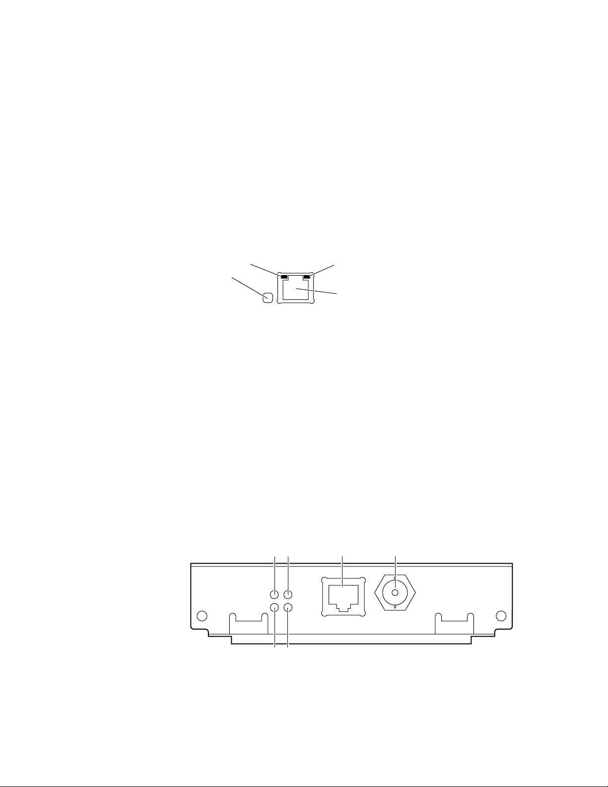
Ethernet connections and indicators
The printer’s built-in Ethernet connector
The printer’s built-in Ethernet connector has the following connections and
indicators:
1.
LINK indicator (Phaser 360 only); on indicates a working connection to a
hub, off indicates no connection to a hub.
2.
RCV indicator (green); blinks while the network interface is receiving.
3.
XMT indicator (yellow); blinks while the network interface is transmitting.
4.
Twisted pair (10BaseT) connector.
2
1
RCV XMT
LNK
Ethernet
3
4
0180-01
PhaserShare Series B Ethernet card
The PhaserShare Series B Ethernet card has the following connections and
indicators:
1.
TX indicator (yellow); blinks while the network interface is transmitting.
2.
RX Link indicator (green); blinks while the network interface is receiving.
3.
Speed indicator (yellow); on indicates 100 Mbps, off indicates 10 Mbps.
4.
Twisted pair connection indicator; on indicates a working connection to a
hub, off indicates no connection to a hub. If the 10Base2 connector (6) is
used, this indicator is off.
5.
Twisted pair (10BaseT or 100BaseTx) connector.
6.
Thin coax (10Base2) connector.
12
PhaserShare Networking Manual
Page 21

Ethernet cables and termination
N O T
E
To fully comply with EMI specifications, the use of shielded or screened cables may
be required. “Shielded” describes IBM-defined cables used with the DB-9
connector. “Screened” describes cables that are electrically similar to Category 4
UTP, but with an added shield or screen.
10BaseT or 100BaseTx (Twisted Pair)
100BaseTx requires Category 5 (100-Ohm UTP) cabling.
The Ethernet standard does not allow a direct 10BaseT connection between a single
computer and a single printer. Use 10Base2 (Thin Ethernet) to connect a single
computer to a single printer.
PhaserShare Series B Network Interfaces
2
C A U T I O
N
Do not use “silver satin” telephone e xtension cables f or 10BaseT networks, either as
drop cords or as patch cables in the wiring closet. (Silver satin cables are flat,
usually silver or gray, with 28-gauge stranded or tinsel conductors.) Do not use
shielded twisted pair cable intended for IBM Token Ring networks or voice-grade
(level 1 or 2) unshielded twisted pair cable for wiring runs. These cables do not
meet the requirements for 10BaseT and will lead to unreliable operation.
10Base2 (Thin Ethernet)
Depending on the type of Ethernet cables you use and your network configuration,
you may need to use terminators at certain points in the installation. Refer to the
manufacturer’s documentation for your Ethernet adapters and cables for details.
10Base5 (Thick Ethernet)
Connecting the printer using thick coax (10Base5) requires an adapter; contact your
dealer to obtain adapters, cables, and terminators.
PhaserShare Networking Manual
13
Page 22

2
9789-06
PhaserShare
TM
Series B
Token Ring Card
TX
RX
INS
16
Mbs
STP
UTP
1234
56
PhaserShare Series B Network Interfaces
PhaserShare Series B Token Ring card
The PhaserShare Series B Token Ring port conforms to the IEEE 802.5 standard.
With the PhaserShare Series B Token Ring card, you can connect the printer directly
to a Token Ring network using shielded twisted pair (STP; IBM Type 1) or
unshielded twisted pair (UTP; IBM Type 3) cables. Contact your dealer to obtain
adapters and cables.
N O T
E
To fully comply with EMI specifications, the use of shielded or screened cables may
be required. “Shielded” describes IBM-defined cables used with the DB-9
connector. “Screened” describes cables that are electrically similar to Category 4
UTP, but with an added shield or screen.
When a PhaserShare Series B card is purchased initially with the printer, it is
installed at the factory. When a PhaserShare Series B card is purchased later as an
upgrade kit, follow the installation instructions that are shipped with the card.
When a PhaserShare Series B Token Ring card is installed in the printer, the printer’s
built-in Ethernet connector is disabled.
C A U T I O
N
To avoid damaging the network interface, turn off the printer before making any
Token Ring connections.
Token Ring connections and indicators
The PhaserShare Series B Token Ring card has the following connections and
indicators on the rear panel:
1.
Shielded Twisted Pair (STP; IBM Type 1) connector (DB-9).
N O T
E
The STP port on the PhaserShare Token Ring card supports cable lengths up to
150 meters (492 feet) from the interface to the MAU (Medium Access Unit),
including lobe and patch cables.
2.
Unshielded Twisted Pair (UTP; IBM Type 3) connector (RJ-45).
3.
Ring speed indicator (yellow); on indicates 16 Mbps, off indicates 4 Mbps.
4.
TX indicator (yellow); blinks while the interface is transmitting.
5.
Connection indicator (green); on indicates that the card is asserting its ring
insertion control signal.
6.
RX indicator (green); blinks while the interface is receiving.
14
PhaserShare Networking Manual
Page 23
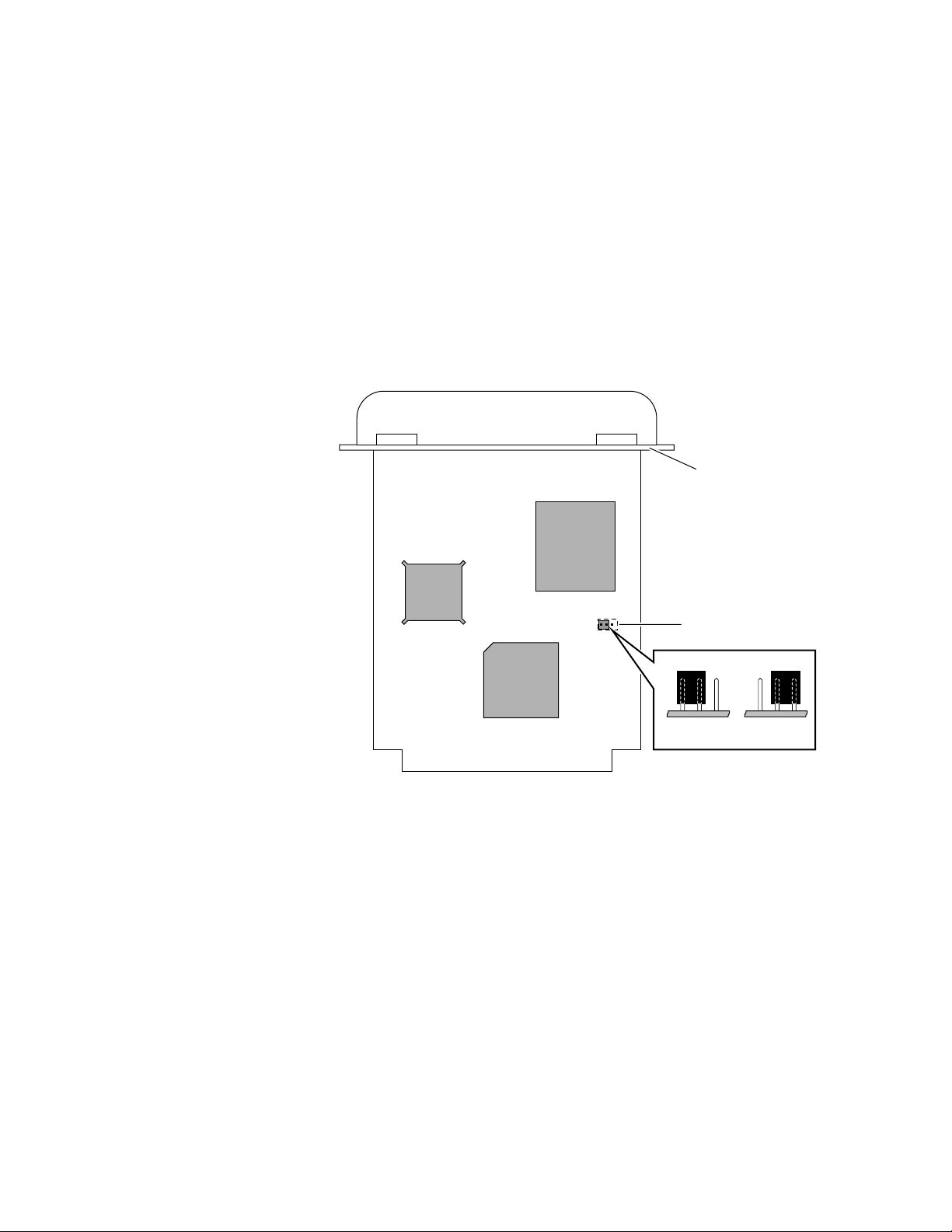
Ring speed jumper
The Token Ring card is equipped with a single three-pin jumper to set the ring speed.
There are two settings: 4 Mbps and 16 Mbps.
N O T
The following illustration shows a top view of the card and the location of the
jumper.
1.
2.
PhaserShare Series B Network Interfaces
E
If you received your printer with the Token Ring card already installed, you must turn
off the printer and remove the card before you change the jumper setting.
Rear panel
Jumper
1
2
2
16 Mbps 4 Mbps
9789-03
PhaserShare Networking Manual
15
Page 24

2
PhaserShare Series B Network Interfaces
Token Ring configuration
You can set the Token Ring Frame Routing from the printer’s front panel. When you
have the Frame Routing set, you may want to set other Token Ring parameters. See
“How to configure Token Ring parameters:” on page 19. See the table “Token Ring
parameters” on page 18 for a list of all settable Token Ring parameters.
Setting the Frame Routing from the Phaser 740 and 360 front panels
When the Token Ring card is installed in the printer, you can set the Frame Routing
from the printer’s front panel. The choices are Transparent (no source routing) or
Source Route (use source routing).
N O T
E
If you are attempting to perform any front panel procedure and you don’t see the
expected menu choices, the front panel may be locked. For information on how to
unlock it, see “If the front panel is locked” on page 165.
1.
Press Menu; the front panel displays Help Pages.
2.
Press ----> or <---- until the front panel displays Network Settings.
3.
Access the Frame Routing menu:
a.
Press Menu until the front panel displays Token Ring.
b.
Press Menu; the front panel displays the first of two Frame Routing
choices.
4.
Select the desired Frame Routing: Transparent or Source Route:
a.
Press ----> until the Frame Routing choice you want is displayed.
b.
Press OK to enter your choice into the printer; the front panel briefly
displays Selected, then returns to the Token Ring display.
5.
Return the printer to normal operation:
a.
Press Exit until the front panel displays Network Settings.
b.
Press Exit again.
■ If you have changed any parameters that require a printer reset to
take effect, you will be prompted to reset the printer. If you press
Reset, the printer resets. If you press Resume, the front panel
displays Network Settings. Press Exit; the printer returns to
normal operation, but the changes you have made will not take
effect until the next time the printer is reset.
■ If you have not changed any parameters that require a printer reset
to take effect, the front panel displays Ready.
16
PhaserShare Networking Manual
Page 25

PhaserShare Series B Network Interfaces
Setting Frame Routing from the Phaser 780 printer front panel
When the Token Ring card is installed in the printer, you can set the Frame Routing
from the printer’s front panel. The choices are Transparent (no source routing) or
Source Route (use source routing).
1.
While Ready is displayed, press Select; the Printer menu is displayed:
Printer Menu
Help Pages Menu
2.
Press the left or right arrow buttons until the front panel displays Network
Settings.
Printer Menu
Network Settings Menu
3.
Press Menu to enter the Network Settings menu; the front panel
displays:
Network Settings
Token Ring Menu
4.
Press Menu again; the front panel displays the first of two Frame Routing
choices.
2
5.
Select the desired Frame Routing: Transparent or Source Route:
a.
Press the right arrow button until the Frame Routing choice you want
is displayed.
b.
Press Select to enter your choice into the printer; the front panel
briefly displays Selected, then displays the selected Frame Routing
choice again.
6.
Return the printer to normal operation:
a.
Press Exit (the far right button) until the front panel displays:
Network Settings
Token Ring Menu
b.
Press Exit again.
■ If you have changed any parameters that require a printer reset to take
effect, you will be prompted to reset the printer. If you press Confirm,
the printer resets. To return to normal operation without resetting the
printer, press Exit (the far right button); Printer Menu appears on
the top line of the display. Press Exit again; the printer returns to
normal operation, but the changes you have made will not take effect
until the next time the printer is reset.
■ If you have not changed any parameters that require a printer reset,
press Exit again; the front panel displays Ready.
PhaserShare Networking Manual
17
Page 26

2
PhaserShare Series B Network Interfaces
Token Ring parameters
Parameter Description Choices
Network Address Token Ring Address (by default, this is a
Speed This read-only parameter reports the ring speed
Early Token
Release
Adapter Status This read-only parameter reports the Token Ring
bit-swapped version of the printer’s Printer ID,
and it is a unique address on the network). You
can supply a Locally Administered Address.
set by the jumper on the card.
The printer releases the token at the end of the
last byte transmitted (not applicable at 4 Mbps).
card status.
The report is in two parts, separated by a
comma:
Adapter status, Details
Adapter status
Ring card.
Route Cache
Size
Route Cache
Timeout
Broadcast For broadcasting to all network nodes.
Unknown Route Used when the printer is searching for a route to
The number of entries in the source route table. 10 to 300.
The time in seconds that an entry remains in the
source route table before being updated.
Changes the default frame type for source route
broadcasts. Broadcast is ignored if Frame
Routing is set to Transparent.
NOTE: Some protocols (for example, IP and
ARP) always use all routes, so they are not
affected by this parameter.
a specific network node. Changes the default
frame type for source route broadcasts.
Unknown Route is ignored if Frame Routing is
set to Transparent.
NOTE: Some protocols (for example, IP and
ARP) always use all routes, so they are not
affected by this parameter.
reports the condition of the Token
Details
reports additional information.
Any valid Token Ring address between
40.
xx.xx.xx.xx.xx
4 Mbps or 16 Mbps.
Enabled (default) or Disabled
Adapter status:
Adapter Initializing. Card is starting up.
Adaptor Open. Card is connected to the
network.
Adapter Closed. Card is not connected to the
network.
Adapter Fault. Card is defective.
Details:
Ring OK. Ready for network communication.
Fault. Internal error; the card is defective.
Cable Disconnected. Cable is not connected to
the card.
Ring Error. Network problem.
Removed by network management. The
network administrator has disabled the
connection.
5 to 65535.
Single Route. The printer uses single-route
broadcasts for most source-route broadcasts.
All Routes. The printer uses all-routes
broadcasts for all broadcasts.
Single Route. The printer uses single-route
broadcasts for most source-route broadcasts.
All Routes. The printer uses all-routes
broadcasts for all broadcasts.
and 7F.
xx.xx.xx.xx.xx
.
18
PhaserShare Networking Manual
Page 27

PhaserShare Series B Network Interfaces
How to configure Token Ring parameters:
■ On UNIX systems, you can use the script config-TokenRing, provided with
the printer’s network utilities software. See the next topic, “Using the
config-TokenRing script”.
■ On PCs, you can edit the PostScript utility file TOKNCFG.PS and send it to
the printer. See the README file in the UTILS directory on the printer’s
CD-ROM for details.
■ On a Macintosh, you can edit the PostScript utility file Configure Token Ring
and send it to the printer. See the ReadMe file in the Network Utilities folder
on the printer’s CD-ROM for details.
■ Windows users on NetWare networks can use the PhaserShare
Administrator. See “Using the PhaserShare Administrator to configure
Token Ring” on page 20.
■ With a TCP/IP connection and a World Wide Web browser, you can use
PhaserLink Printer Management Software. See “Using PhaserLink Printer
Management Software to configure Token Ring” on page 21.
Whichever method you use, you must reset the printer to make the changes take
effect. For more information, see Chapter 16, “Resetting the Printer”.
2
Using the
The UNIX shell script config-TokenRing is provided with the printer’s network
utilities software. The script creates a PostScript file containing the Token Ring
parameters. Set the Token Ring parameters by sending the PostScript file to the
printer.
Before performing this procedure, you must install the script on your host computer.
If you have not already installed the file, see “Extracting files from unix.tar” on
page 52. Your host spooling system must also be configured; see Chapter 8, “TCP/IP
Host Configuration (UNIX)”.
1.
2.
3.
config-TokenRing
Connect the printer to the network. ARP (Address Resolution Protocol)
requires that the printer be connected on the same physical network
segment as the host. You will be using the arp command later in this
procedure.
Log in.
Run the script config-TokenRing:
a.
Change (cd) to the bin subdirectory in the directory where you placed
your printer’s network utilities.
b.
Type the name of the script, redirecting the output to a file. Type:
config-TokenRing > filename
script
4.
When prompted by the script, enter the Token Ring parameters.
5.
When the script is finished, log in as root.
PhaserShare Networking Manual
19
Page 28

2
PhaserShare Series B Network Interfaces
6.
Make an entry into the host’s ARP (Address Resolution Protocol) table
defining the printer’s Printer Name/Token Ring address pair. In general,
this requires a command corresponding to one of the following syntax
examples:
or
See the documentation for your host system for specifics of this command.
7.
Turn on the printer.
8.
Use the host spooling system (for example, lpr or lp) to send the file you
created in Step 3b to the printer; this stores the Token Ring information in
the printer’s internal memory, where it is retained over a reset or power
cycle.
9.
You must reset the printer before the changes take effect. For more
information, see Chapter 16, “Resetting the Printer”.
Using the PhaserShare Administrator to configure Token Ring
arp -s printer-name Token-Ring-address (for BSD systems)
arp -s ether printer-nam e Token-Ring-address (for System V)
1.
In the PhaserShare Administrator Main window, select the desired printer
from the Printer List.
2.
Click Configure Printer; this displays the Configure Printer dialog box.
3.
In the Configure Printer dialog box, click the Token Ring tab.
4.
In the Token Ring tab, set the Token Ring parameters as desired.
5.
Click OK.
6.
You are prompted to reset the printer. You must reset the printer before the
changes take effect. For more information, see Chapter 16, “Resetting the
Printer”.
For more information on the PhaserShare Administrator, see Chapter 5,
“PhaserShare Administrator Software for NetWare Networks”.
20
PhaserShare Networking Manual
Page 29

PhaserShare Series B Network Interfaces
Using PhaserLink Printer Management Software to configure Token Ring
For information on connecting to your printer via PhaserLink Printer Management
Software, see “Accessing printer information from a browser” on page 122. For
general information on PhaserLink Printer Management Software, see Chapter 12,
“PhaserLink Printer Management Software”.
1.
From the printer’s home page, click Configuration; this displays the View
and Configure Settings page.
2.
From the View and Configure Settings page, click View and Configure
Interface Settings; this displays the View and Configure Interface
Settings page.
3.
From the View and Configure Interface Settings page, click View and
Configure PhaserShare Settings (Token Ring card); this displays the View
and Configure PhaserShare Settings page for Token Ring.
4.
Enter your settings into the fields for Token Ring Address, Speed, and
Bridging. If you make an error, click Restore Initial Form Values and start
again.
5.
When you are finished entering the settings, enter the Validation Password
and click Do/Apply. If you are not sure of the password, contact your
system administrator.
2
6.
You must reset the printer before the changes take effect. For more
information, see Chapter 16, “Resetting the Printer”.
PhaserShare Networking Manual
21
Page 30
2
9789-07
TX
RX
LocalTalk®
PhaserShare
TM
Series B
LocalTalk Card
13
2
PhaserShare Series B Network Interfaces
PhaserShare Series B LocalTalk card
With the PhaserShare Series B LocalTalk card, you can connect the printer to a
LocalTalk network. Both the LocalTalk connection on the card and the Ethernet
connector on the printer’s rear panel are simultaneously active.
When a PhaserShare Series B card is purchased initially with the printer, it is
installed at the factory. When a PhaserShare Series B card is purchased later as an
upgrade kit, follow the installation instructions that are shipped with the card.
LocalTalk connection
N O T
E
LocalTalk is sometimes referred to as AppleTalk. LocalTalk refers to the physical
connection; AppleTalk is the protocol.
You can make LocalTalk connections between the printer and a single computer or a
LocalTalk network. If your LocalTalk installation is complex, or if you need
assistance, contact your network system administrator.
C A U T I O
N
Connect your printer to a LocalTalk network before you turn on the printer.
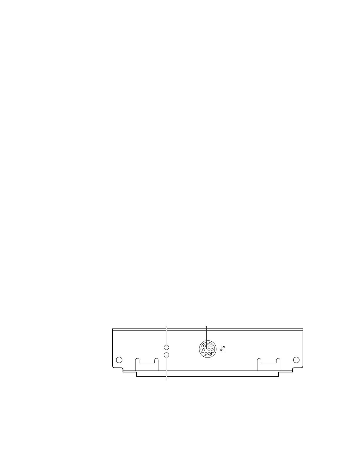
The PhaserShare Series B LocalTalk card has the following connections and
indicators on the rear panel:
1.
TX indicator (yellow); blinks while the interface is transmitting.
2.
RX indicator (green); blinks while the interface is receiving.
3.
LocalTalk connector; 8-pin, circular DIN.
N O T
E
Both indicators flashing together indicates a fatal software error . Turn the printer off,
then on again; if the problem persists, replace the card.
22
PhaserShare Networking Manual
Page 31

PhaserShare Series B Network Interfaces
LocalTalk connectors and cables
LocalTalk connectors and cables are available through your local reseller. This
illustration shows two commonly used types of LocalTalk connectors:
1.
Self-terminating connector
2.
Connector that requires an external terminator, depending on your
network configuration
0180-0212
N O T
E
Depending on the type of LocalTalk cables you use and your network configuration,
you might need to use terminators at certain points in the installation. Refer to the
documentation for your LocalTalk connectors and cables for details.
2
Connecting to a single computer
You can use LocalTalk connectors and cables to connect the printer directly to your
computer, without connecting it to any other network. To avoid damaging the
network interface, turn off the printer before making any LocalTalk connections.
1.
Connect the short cable of a LocalTalk connector to the PhaserShare
LocalTalk port.
2.
Connect the short cable of another LocalTalk connector to your computer’s
LocalTalk port.
3.
Connect a LocalTalk cable from the LocalTalk connector that you have just
attached to your computer to the printer’s LocalTalk connector.
TX
LocalTalk®
RX
TM
PhaserShare
Series B LocalTalk Card
1
3
2
9789-08
Depending on the type of LocalTalk connectors you use and your network
configuration, you might need to use external terminators. Refer to the
documentation for your LocalTalk connectors and cables for details.
PhaserShare Networking Manual
23
Page 32

2
PhaserShare Series B Network Interfaces
24
PhaserShare Networking Manual
Page 33

Chapter
3
EtherTalk, LocalTalk, and TokenTalk Configuration
Before you begin
Before you begin the configuration, complete the following steps:
■ Your printer should be set up, connected to the network, and turned on.
See your printer’s user documentation for information about setting up
and turning on the printer. For information about connecting the printer to
the network, see Chapter 2, “PhaserShare Series B Network Interfaces”.
■ Install the Tektronix driver for your printer on every Macintosh and PC
that will send print jobs to the printer. For details on driver installation, see
your printer’s user documentation.
Configuration overview
N O T
E
The printer’s AppleTalk connection works with Macintosh system software, 7.0, 7.1,
7.5, 7.6, 8.0, 8.1, and 8.2.
The configuration procedure for LocalTalk, EtherTalk, and TokenTalk consists of two
simple steps:
1.
Print the Configuration Page. It reports the printer’s default name, which
you need for EtherTalk and TokenTalk configurations. For information on
printing a Configuration Page, see “The printer’s Configuration Page” on
page 6.
2.
Verify that the printer is in the Chooser. See “Finding the printer’s name in
the Chooser” on page 26.
■ If the printer is not in the Chooser, see “Troubleshooting” on page 30.
■ If the printer is in the Chooser, you may want to change the printer’s
name or zone. See “Changing the printer’s name (optional)” on
page 27 and “Changing the printer’s EtherTalk/TokenTalk zone
(optional)” on page 29.
N O T
E
The default language for the LocalTalk, EtherTalk, and TokenTalk ports is
PostScript. Refer to your printer’s user documentation for information about
changing the printer’s default language.
PhaserShare Networking Manual
25
Page 34

3
EtherTalk, LocalTalk, and TokenTalk Configuration
Finding the printer’s name in the Chooser
1.
From the Apple menu, select Chooser.
2.
In the upper-left corner of the Chooser, find the driver icon. (If the driver
icon does not appear in the Chooser, install the printer driver.) Click the
driver icon.
3.
If a list of zones appears in the lower-left portion of the Chooser, select the
proper zone.
N O T
E
The printer’s default zone is listed on the Configuration Page in the EtherTalk
or TokenTalk field. For more information on the Configuration Page, see “The
printer’s Configuration Page” on page 6.
4.
A list of printers appears in the right portion of the Chooser; find your
printer’s name in the list. The printer’s default name is listed on the
Configuration Page (see “The printer’s Configuration Page” on page 6). If
the name does not appear, check the cable connection between your printer
and the network.
N O T
E
It is possible for the Printer Name field on the Configur ation P age to be b lank.
When the printer is powered up, it uses a def ault name and then checks to see
that no other printer on the network has the same name. If enough printers
with the same default name are present it can take several minutes for the
printer to establish a unique name. If the name field is blank, wait a short time
and reprint the Configuration Page.
26
PhaserShare Networking Manual
Page 35

EtherTalk, LocalTalk, and TokenTalk Configuration
Changing the printer’s name (optional)
There are three ways to change the printer’s name:
■ Use the Apple Printer Utility; see “Changing the printer’s name: Apple
Printer Utility” on page 28.
■ With a TCP/IP connection and a World Wide Web browser, you can use
PhaserLink Printer Management Software; see “Changing the printer’s
name: PhaserLink Printer Management Software” on page 28.
■ With a PC running Windows on a NetWare network, you can use the
PhaserShare Administrator; see “Changing the printer’s
EtherTalk/TokenTalk zone (optional)” on page 29.
The name selected here prints on the Startup Page and Configuration Page; the name
also appears in the Chooser on a Macintosh. The name can be up to 31 characters
long. It may contain any printable characters; however, the characters @ : = * are
deleted from the name used on AppleTalk. A change is persistent across printer
power cycles.
3
Notes regarding printer names
■ If you have more than one printer in the same zone and you choose a name
for one printer that is already assigned to another, the second printer
registers itself on the network with the number 1 appended to the name.
For example, if you attempt to assign a printer the name TekPhaser and
another printer in the zone already has the same name, the printer you are
naming appears on the network as TekPhaser-1.
■ The added number is recalculated each time the printer is turned on. If you
have more than one printer with the same name on the network, the
printers’ names on the network depend on the order in which the printers
are turned on. To avoid this confusion, it is recommended that you assign
each printer on the network a unique name.
■ The added number appears in the Chooser, on the printer’s front panel,
and on the Startup Page. On the Configuration Page, the name, without the
characters @ : = *, and with the added number, appears in the EtherTalk,
LocalTalk, and TokenTalk areas. The Printer Name under General
Information is the name as it was set, not as it appears in the Chooser.
PhaserShare Networking Manual
27
Page 36

3
EtherTalk, LocalTalk, and TokenTalk Configuration
Changing the printer’s name:
1.
Locate the Apple Printer Utility, included with your printer’s network
utilities software.
2.
Double-click the Apple Printer Utility icon; the Printer Selector
window is displayed.
3.
Select the zone (if applicable) and the printer. Click Open Printer; a
dialog box is displayed containing Printer Information and Printer
Preferences.
4.
Click the triangle to the left of Printer Preferences. Click the triangle to
the left of Name; this displays a dialog box containing a field for the
printer’s name. Enter the new name in the field.
5.
Click Send.
6.
To reselect the printer with its new name, open the Chooser.
Apple Printer Utility
Changing the printer’s name: PhaserLink Printer Management Software
1.
From the printer’s home page, click Configuration; this displays the
View and Configure Settings page.
2.
On the View and Configure Settings page, click View and Configure
Interface Settings.
3.
On the View and Configure Interface Settings page, click View and
Configure EtherTalk Settings, View and Configure LocalTalk
Settings, or View and Configure TokenTalk Settings.
4.
In the Printer Name field, enter the desired printer name.
For more information on PhaserLink Printer Management Software, see Chapter
12, “PhaserLink Printer Management Software”.
28
PhaserShare Networking Manual
Page 37

EtherTalk, LocalTalk, and TokenTalk Configuration
3
Changing the printer’s EtherTalk/TokenTalk zone (optional)
There are two ways to change the printer’s zone:
■ With a TCP/IP connection and a World Wide Web browser, you can use
PhaserLink Printer Management Software; see “Changing the printer’s
zone: PhaserLink Printer Management Software” on page 29.
■ You can also change the printer’s zone using PostScript utility files; see the
README files on the printer’s CD-ROM. The Macintosh README file is
in the Network Utilities folder; the PC README file is in the UTILS
directory.
Changing the printer’s zone: PhaserLink Printer Management Software
1.
From the printer’s home page, click Configuration; this displays the View
and Configure Settings page.
2.
On the View and Configure Settings page, click View and Configure
Interface Settings page.
3.
On the View and Configure Interface Settings page, click: View and
Configure EtherTalk Settings, or View and Configure TokenTalk
Settings.
4.
In the Zone field, enter the desired zone.
For more information on PhaserLink Printer Management Software, see Chapter 12,
“PhaserLink Printer Management Software”.
PhaserShare Networking Manual
29
Page 38

3
EtherTalk, LocalTalk, and TokenTalk Configuration
Troubleshooting
If the printer is not in the Chooser, use the following troubleshooting procedure.
1.
Check that the Configuration Page shows a printer name, a node number,
and a zone.
■ If there is no node number, verify that the printer is properly cabled to
the network. Test the cable segment by plugging in a new cable
segment or using the cable segment of a printer that is in the Chooser.
■ If your network uses zones, and there is no zone name on the
Configuration Page, or if the Configuration Page shows the wrong
zone, see “Changing the printer’s EtherTalk/TokenTalk zone
(optional)” on page 29.
N O T
E
The printer cannot create a zone; it must already exist.
2.
If the Configuration Page shows the correct printer name, node number,
and zone, and the printer is still not visible in the Chooser, check the
following items:
■ If there is a Novell NetWare server on the network, verify that the
NetWare server has been configured for Phase 2 routing and
addressing.
■ If there is a Windows NT server on the network, verify that the printer
has not been captured by a Windows NT machine.
■ If the printer continually reboots when connected to the network, it is
possible that a router is broadcasting a zone of *, which is an invalid
zone.
■ If using QuickDraw GX, the GX drivers must be installed. If you don't
use QuickDraw GX, disable the QuickDraw GX, QuickDraw Helper,
and ColorSync extensions.
30
PhaserShare Networking Manual
Page 39

Chapter
4
Novell NetWare Configuration
The printer’s NetWare interface
The printer’s NetWare interface supports the Print Server (PSERVER) operating
mode. Under the NetWare networking model, print jobs are stored in queues
(directories) on a file server. A print server takes print jobs from the queues and
sends them to printers. In your Tektronix printer, the print server resides within the
internal interface of the printer, so the print server and the printer are one. The
printer logs in to a file server using a login connection to service specified queues.
Bindery mode and NDS (NetWare Directory Services) supported
The printer’s NetWare interface supports Bindery and NDS connection modes
separately or simultaneously.
Supported NetWare versions
The printer’s NetWare interface has been tested with NetWare versions 3.12, 4.1, and
4.11. It should work with any NetWare server that uses NetWare’s QMS (Queue
Management System) to manage and service print queues. These servers include
80286-, 80386-, and 80486-based servers running other versions of NetWare (for
example, versions 2.15, 2.2, 3.0, 3.11, 4.0), DOS and OS/2-based systems, VMS
servers, and servers running UnixWare. The PhaserShare NetWare interface is not
compatible with systems running NetWare Lite.
Supported NetWare protocols
The printer’s NetWare interface supports the following NetWare protocols:
■ NCP (NetWare Core Protocol)
■ IPX (Internet Packet Exchange)
■ SPX (Sequential Packet Exchange)
■ SAP (Service Advertising Protocol)
■ RIP (Router Information Protocol)
■ NEST (Novell Embedded Systems Technology)
■ SNMP (Simple Network Management Protocol)
PhaserShare Networking Manual
31
Page 40

4
Novell NetWare Configuration
Other features
Passwords
The printer’s NetWare interface supports up to 32 queues and eight file servers in
any combination when in bindery mode. No additional VAPs (Value Added
Procedures), NLMs (Network Loadable Modules), or TSRs (Terminate Stay Resident
programs) are required to install your Tektronix printer on the network.
N O T
E
The printer’s NetWare interface supports packet signature and IPX checksum
automatically, that is, the print server automatically signs packets and/or calculates
checksums upon request from the file server.
If a password is used in Bindery mode, it must be set on the printer with the
PhaserShare Administrator (or PhaserLink Printer Management Software) and on
the file server with PCONSOLE.
If a password is used in NDS mode, it must be set on the printer with the
PhaserShare Administrator (or PhaserLink Printer Management Software) and on
the file server with the NWAdmin utility or PCONSOLE.
Notify lists
Use the PhaserShare Administrator to set up notify lists on NetWare 3.x servers.
On NetWare 4.1, use the NWAdmin utility to set up the notify list for a printer.
Before beginning the configuration procedure
Before you begin the NetWare configuration, complete the following steps:
■ Set up the printer and connect it to the network. See your printer’s user
documentation for information about setting up and turning on the printer.
For information about connecting the printer to the network, see Chapter 2,
“PhaserShare Series B Network Interfaces”.
■ Install the Tektronix driver for your printer should be installed on every
computer that will be sending print jobs to the printer. For details on
driver installation, see the printer’s user documentation.
■ To speed the setup process and avoid conflicts, familiarize yourself with
the components of your network. You should know which version(s) of
NetWare are installed, which versions of client software are used, and the
network topology (frame types, routers, hubs, and cabling).
32
PhaserShare Networking Manual
Page 41

Configuration software for NetWare
Windows software
■ PhaserShare Administrator (Tektronix). Use this application to configure
the printer and the network when using NetWare 3.x and 4.x.
■ NWAdmin (Novell). Use this utility to manage existing queues on
networks running NetWare 4.x in NDS mode.
DOS software
■ NWSET (Tektronix). Use this application to configure the printer with
NetWare 3.x and 4.x. For more information on NWSET, see the README
file in the NETWARE directory of the printer’s or CD-ROM.
■ NWCONFIG.PS (Tektronix utility file). In DOS environments and other
non-Windows environments, you can use this to configure the printer for
NetWare 4.x networks. The PostScript code contained in the file
NWCONFIG.PS is also available in a Macintosh file called Configure
NetWare. For more information on NWCONFIG.PS, see the README file in
the UTILS directory of the printer’s or CD-ROM. For more information on
Configure NetWare, see the ReadMe file in the Network Utilities directory of
the printer’s or CD-ROM.
Novell NetWare Configuration
4
■ PCONSOLE (Novell). Use this utility to manage existing queues with
NetWare 3.x and 4.x (both Bindery and NDS modes).
NetWare configuration for Windows environments
This is a quick configuration procedure using the Tektronix PhaserShare
Administrator. For information on installing the PhaserShare Administrator, see
Chapter 5, “PhaserShare Administrator Software for NetWare Networks”. For
detailed information on the PhaserShare Administrator, functions, see the
PhaserShare Administrator on-line help.
Printing the Configuration Page
Your printer’s Configuration Page reports information that you need for NetWare
configuration. For information on printing a Configuration Page, see “The printer’s
Configuration Page” on page 6.
N O T
E
On the printer’s Configuration Page, all zeros in one or more of the IPX Networks
fields indicates that the printer does not recognize the network connection; this
probably indicates a faulty cable connection, an incorrect frame type, or Reply to
Get Nearest Server has not been set to on. It m ust be set to on f or at least one file
server or router on the same segment as the printer.
PhaserShare Networking Manual
33
Page 42

4
Novell NetWare Configuration
Using the PhaserShare Administrator Quick Configuration Wizard
Log on to the file server
NetWare 3.x. Log on to the default NetWare file server as SUPERVISOR or
SUPERVISOR equivalent. Many of the operations performed using the PhaserShare
Administrator require SUPERVISOR privileges (for example, creating queues).
NetWare 4.x. In Bindery mode, log on to the default NetWare file server as
SUPERVISOR, SUPERVISOR equivalent, or ADMIN /B. Many of the operations
performed using the PhaserShare Administrator require SUPERVISOR privileges
(for example, creating queues).
NetWare 4.x, NDS (NetWare Directory Services) mode. Log on to the default
NetWare file server as ADMIN or ADMIN equivalent. Many of the operations
performed using the PhaserShare Administrator require ADMIN privileges (for
example, creating queues).
N O T
E
While not required, it is recommended that you log in only to the file servers to be
configured with this printer.
Start the PhaserShare Administrator
To start the PhaserShare Administrator, double-click the PhaserShare Administrator
icon. Refer to your Windows documentation for complete information on how to
start applications. For information on installing the PhaserShare Administrator, see
“Installation” on page 44.
When you start the PhaserShare Administrator, the Main window is displayed.
34
PhaserShare Networking Manual
Page 43

Novell NetWare Configuration
Select a print server
In the Main window Printer List, click the print server name/printer name.
N O T
E
If the printer does not show up in the list of available printers, there could be a
network hardware problem, an incorrect frame type, or incorrect search options
settings (see “Printer does not appear in the Main window printer list” on page 36).
Launch the Quick Configuration Wizard
Click Quick Configuration to launch the Quick Configuration Wizard.
4
Configure the printer and set up queues
1.
If desired, change the Print Server Name or Printer Name.
2.
Select connection mode(s) by checking the box(es) for Bindery Services,
NDS Services, or both (the Phaser 740, 780, and 360 printers support both).
3.
Click Next. The dialogs that follow allow you to configure Bindery
connections, NDS connections, or both. Supply the following information
for these connections:
Information needed for Bindery connections
Select either the configuration file server or the preferred file server from
the drop-down list; click Next.
If the file server you want is not on the list, proceed with these steps:
a.
Click File Servers to display the File Servers Browse dialog box.
b.
Select the server you want. Click OK. You are returned to the File
Server Selection dialog box.
c.
Select either the configuration file server or the preferred file server
from the drop-down list. Click Next.
Create and select a new queue, or select an existing queue; click Finish.
PhaserShare Networking Manual
35
Page 44

4
Novell NetWare Configuration
Information needed for NDS connections
■ Specify the current Directory Services Tree; (the tree where the print
server will reside).
■ Specify the current Directory Services Context. (the location in the
directory services tree where the print server will reside).
■ Create and select a new queue, or select an existing queue; click Finish.
Verify information and finish the configuration
After you have entered the configuration information, the Quick Configuration
Wizard displays the Configured Printer Information dialog box, which reports the
information you have entered.
1.
Verify that the information is correct.
■ If the information is correct, click Apply Changes.
■ If the information is not correct, click Back to return to previous dialog
boxes and correct the information. Click Next to return to the
Configured Printer Information dialog box. Click Apply Changes.
■ To exit the wizard and return to the Main window without making any
changes, click Cancel.
2.
After you click Apply Changes, the printer resets; the changes take effect
when the reset is complete.
3.
After the reset, you are prompted to print a test page. It is recommended
that you print a test page to verify a successful installation.
Troubleshooting Windows configurations
Printer does not appear in the Main window printer list
1.
Make sure that the printer is turned on and properly connected to the
network. Try a different network drop or port.
2.
Make sure that NetWare is enabled on the printer. This is reported on the
printer’s Configuration Page in the NetWare field. For information on
enabling and disabling protocols, see Chapter 15, “Disabling Protocols”.
If you are using bindery emulation, make sure that NDS is disabled. From
the PhaserShare Administrator Print Server tab, uncheck the Directory
Services checkbox.
36
3.
If your network uses a router, configure the router to not suppress NetWare
SAP (Service Advertising Protocol) packets or packets of the frame type the
printer is using.
PhaserShare Networking Manual
Page 45

Novell NetWare Configuration
Testing from the PhaserShare Administrator
The following steps provide a simple test of the Administrator:
1.
Click Search Options.
2.
In the Search Options dialog box, click the following radio buttons:
a.
Sort by: Print Server Name
b.
Select by: All Tektronix Printers
3.
Click OK.
Look at the list of printers. If the Printer Name is listed as <Information Not
Available>, the Administrator is unable to communicate with the printer using
SNMP over IPX; this indicates that either the printer selected is an unsupported
printer or the network configuration is incorrect. If the printer is not listed, check the
printer’s Configuration Page for network errors.
N O T
E
The PhaserShare Administrator displays an SNMP error when the client computer
running the PhaserShare Administrator is not attached to a file server with the same
frame type as the printer is using. The same error is displayed if a version of the
PhaserShare Administrator below 3.6 is used to configure a Phaser 740, 780, or
Phaser 360 printer. The Printer Not Responding dialog box is displayed with the
message: This printer is not responding to SNMP queries. Please check the
printer and try again. Click OK and correct the problem.
4
Testing the file server-to-printer connection
1.
First use the CAPTURE command to redirect an LPT port output to a
network queue. For example:
CAPTURE NB NFF NT Q=PHASER L=1
where:
NB specifies NO BANNER
NFF specifies NO FORM FEED
NT specifies NO TABS
Q=PHASER specifies PHASER as the queue name
L=1 specifies port LPT1
2.
Use any text editor to create a two-line ASCII file with the following
contents:
%!
showpage
3.
Use the COPY command to send the file to the printer. For example, if the
file is called SHOWPAGE, and the printer is assigned to LPT1, type:
COPY SHOWPAGE LPT1:
If the file server-to-printer connection is functional, the printer ejects a
blank page.
PhaserShare Networking Manual
37
Page 46

4
Novell NetWare Configuration
Cannot submit job to a queue
Use the NWAdmin to verify that the user is a queue user.
1.
Log in as ADMIN and launch the NWAdmin utility. Browse the directory
services tree to the location of the print queue object for this printer.
Double-click the print queue object to view its properties.
2.
The identification view is displayed by default. If it is not displayed, select
it. Make sure that all of the Operator Flags at the bottom left corner of the
window are checked.
3.
Click Users; this view displays a list of queue users and queue user groups.
Verify that the list of users, groups, and group memberships are correct.
For more details, consult the NetWare Administrator documentation.
4.
Click Assignment; this view displays the print servers and printers
assigned to service this print queue. Assign the appropriate objects to this
print queue.
N O T
E
For the print server to attach and service the print queue, the print server object
name in the tree must match the print server name in the printer.
Job appears in queue, but printer does not service it
1.
Verify that the printer has been set up to service the queue.
a.
Log in as ADMIN and launch the NWAdmin utility. Browse the
directory services tree to the location of the print queue object for this
printer. Double-click the print queue object to view its properties.
b.
Click Assignment; this view displays the print servers and printers
assigned to service this print queue.
c.
The Authorized print servers window and the Printers servicing print
queues window should list the names of the objects linked to this print
queue. If a print server object is not linked to this print queue, create or
modify a print server object and assign it to this print queue. If a
printer object is not linked to this print queue, create or modify a
printer object and assign it to this print queue. See the NetWare user
documentation for more details.
2.
Check that the printer was able to log in to the file server:
a.
At the file server’s console, type:
load monitor
b.
From the Available Options menu, select Connection Information.
If the printer has logged in, its print server name is displayed in the list. If
the print server name is not on the list, continue with Steps 3 through 5.
38
PhaserShare Networking Manual
Page 47

Novell NetWare Configuration
3.
Verify that there was an available connection slot for the printer. Since the
printer consumes a login connection, the file server may need an available
connection for the printer to log in.
4.
Verify that the password the printer saved (if one was set) is the same as the
one on the file server. Mismatched passwords can result if PCONSOLE,
rather than the PhaserShare Administrator, is used to set the password.
Use the PhaserShare Administrator to enter a new password to ensure that
they are the same. In the Print Server tab, click Set Password; this displays
the Set Password dialog box. Enter the password in both fields and
click OK.
5.
Verify that the printer’s print server name matches the one in the NDS tree.
The Configuration Page reports the printer’s print server name. For
information on printing a Configuration Page, see “The printer’s
Configuration Page” on page 6.
6.
Verify that the frame type the printer is using is supported by the file
server. See “Printer does not appear in the Main window printer list” on
page 36.
7.
Verify that at least one file server or router on the same segment as the
printer has Reply to Get Nearest Server set to on.
4
Job is serviced, but does not print
■ Check the PhaserShare Administrator Printer Info dialog box for reported
error conditions.
■ Download the PostScript Error Handler to the printer. For information on
using the Tektronix PostScript Error Handler, see your printer’s user
documentation.
■ Use the correct Tektronix driver for your networked printer.
■ Verify that the Print Server protocol is enabled; use the printer’s front panel
or check the Administrator’s Print Server tab.
■ Banners, form feeds, and tabs may interfere with the print job.
Try disabling these from the driver/network setup.
PhaserShare Networking Manual
39
Page 48

4
Novell NetWare Configuration
Setting IPX frame types from the front panel
Setting IPX frame types: Phaser 840
1.
When the front panel displays READY TO PRINT, press the down-arrow
button until Menu is highlighted. Press Select.
2.
Press the down-arrow button until Printer Configuration is
highlighted. Press Select.
3.
Press the down-arrow button until Network Settings is highlighted.
Press Select.
4.
Press the down-arrow button until NetWare is highlighted. Press Select.
5.
Press the down-arrow button until IPX Frame Type is highlighted. Press
Select.
6.
Press the down-arrow button until the desired frame type is highlighted.
Press Select until On is displayed. If desired, you can set more than one
frame type.
7.
To return the printer to normal operation, press the down-arrow button
until Exit is highlighted. Press Select.
Setting IPX frame types: Phaser 740 and Phaser 360 printer
N O T
E
If you are attempting to perform any front panel procedure and you don’t see the
expected menu choices, the front panel may be locked. For information on how to
unlock it, see “If the front panel is locked” on page 165.
1.
Enter the Network Settings menu:
a.
Press Menu; the front panel displays Help Pages.
b.
Press ----> or <---- until the front panel displays Network
Settings.
c.
Press Menu; the front panel displays TCP/IP.
2.
Access the menu of frame types:
a.
Press ----> until the front panel displays NetWare.
b.
Press Menu; the front panel displays Enable Interface.
c.
Press ---->; the front panel displays IPX Frame Type.
40
d.
Press Menu; the front panel displays the first in a menu of frame types.
PhaserShare Networking Manual
Page 49

Novell NetWare Configuration
3.
Enable or disable the frame type:
a.
Press ----> until the frame type you want is displayed.
b.
Press Menu to display the current status of the frame type:
Enabled or Disabled.
c.
Press ----> until the frame type is either Enabled or Disabled,
as desired.
d.
Press OK to enter your choice into the printer. The front panel
briefly displays Selected, then returns to the display of the frame
type name.
4.
You can set more than one frame type; to set other frame types, repeat
Step 3.
5.
Return the printer to normal operation:
a.
Press Exit (the far left button) until the front panel displays Network
Settings.
b.
Press Exit again.
4
■ If you have changed any parameters that require a printer reset
to take effect, you are prompted to reset the printer. If you press
Reset, the printer resets. If you press Resume, the front panel
displays Network Settings. Press Exit (the far left button);
the printer returns to normal operation, but the changes you
have made do take effect until the next time the printer is reset.
■ If you have not changed any parameters that require a printer
reset to take effect, the front panel displays Ready.
Setting IPX frame types: Phaser 780 printer
1.
Enter the Network Settings menu:
a.
While Ready is displayed, press Select; the Printer menu is
displayed:
Printer Menu
Help Pages Menu
b.
Press the left or right arrow buttons until the front panel displays
Network Settings.
Printer Menu
Network Settings Menu
c.
Press Menu to enter the Network Settings menu; Network
Settings appears on the top line of the display.
PhaserShare Networking Manual
41
Page 50

4
Novell NetWare Configuration
2.
Access the menu of frame types:
a.
Press the right arrow button until the front panel displays NetWare.
b.
Press Menu; the front panel displays Interface.
c.
Press the right arrow button until the front panel displays IPX Frame
Type.
d.
Press Menu; the front panel displays the first in a menu of frame types.
3.
Enable or disable the frame type:
a.
Press the right arrow button until the frame type you want is
displayed.
b.
Press Menu to display the current status of the frame type: On or Off.
c.
Press the right arrow button until the frame type is either On or Off, as
desired.
d.
Press Select to enter your choice into the printer. The front panel
briefly displays Selected, then returns to the display of the frame
type name.
e.
Press Exit (the far right button) to return to the menu of frame types.
4.
You can set more than one frame type; to set other frame types, repeat
Step 3.
5.
Return the printer to normal operation:
a.
Press Exit (the far right button) until Network Settings appears on
the top line of the display.
b.
Press Exit again.
■ If you have changed any parameters that require a printer reset to take
effect, you will be prompted to reset the printer. If you press Confirm,
the printer resets. To return to normal operation without resetting the
printer, press Exit (the far right button); Printer Menu appears on
the top line of the display. Press Exit again; the printer returns to
normal operation, but the changes you have made will not take effect
until the next time the printer is reset.
■ If you have not changed any parameters that require a printer reset,
press Exit again; the front panel displays Ready.
42
PhaserShare Networking Manual
Page 51

Chapter
5
PhaserShare Administrator Software for NetWare Networks
PhaserShare Administrator software makes your Tektronix color printer easier to use
in a NetWare environment. It provides network administrators with printer
management capabilities, job accounting information, and configuration
information.
This chapter provides instructions for installing the PhaserShare Administrator. This
chapter also provides basic information on how to use the PhaserShare
Administrator. Chapter 4, “Novell NetWare Configuration”, provides quick
configuration instructions. More detailed information on using the PhaserShare
Administrator is available through the PhaserShare Administrator’s on-line help.
Introduction to the PhaserShare Administrator
The PhaserShare Administrator is a powerful tool for network and system
administrators designed to simplify administration and make Tektronix printers
easy to share. The PhaserShare Administrator’s key features are listed here:
■
Printer configuration reporting.
network settings. You can remotely set the print server name, IPX frame
types, and many more NetWare parameters, bringing printer control to
your desktop.
■
Printer management.
management tool for network administrators. With real time printer
messages and access to a remote printer control panel, administrators can
resolve many printing problems without leaving their desks. By using the
Notify List to send printer alerts, the network administrator is the first to
know if a printing problem exists.
■
Network configuration.
driver distribution and queue management. Once you install a Tektronix
printer driver on a network server, the driver is automatically available to
all network users.
■
Job accounting.
individual user and job on NetWare networks.
The PhaserShare Administrator is a valuable printer
The PhaserShare Administrator supports automatic
Job accounting allows you to track printer usage by
You can control printer settings and
PhaserShare Networking Manual
43
Page 52

5
PhaserShare Administrator Software for NetWare Networks
NetWare configuration with the PhaserShare Administrator
The PhaserShare Administrator allows you to configure and administer your
Tektronix printer and the queues it services, while providing functionality not
available with PCONSOLE. The PhaserShare Administrator allows you to control
parameters that can be set from PCONSOLE. It also allows you to control the
following printer-specific parameters not supported by PCONSOLE:
■ Printer connection type
■ Frame type
■ Queue scan interval
■ Configuration file server
■ Error notification
■ Resetting the printer (Phaser 740 and 360 printers)
■ Print server name
■ Printer login password
■ Banner printing on a per-queue basis
The PhaserShare Administrator is compatible with NetWare 3.x and 4.x.
Installation
System requirements
■ A Tektronix color printer equipped with an Ethernet card or a Token Ring
card.
■ Microsoft Windows 3.1, 3.11 (or later), Windows for Workgroups 3.11,
Windows NT 4.0, or Windows 95 installed on workstations with standard
memory. The workstation must be at least an 80286 PC.
■ Novell NetWare 2.x, 3.x, and 4.x networks with shells 3.26 or above and
IPX version 3.10 or above.
N O T
E
To determine your network IPX version, use the NetWare NVER command.
The IPX version is not shown when using the IPXODI ? command.
■ Supervisor or equivalent permission on all NetWare 3.x file servers to be
configured.
44
and/or
■ Administrator or equivalent permission on all NetWare 4.x networks to be
configured.
PhaserShare Networking Manual
Page 53

Installation methods
The installer supports the following installation methods:
■ Standard install. This is the recommended installation method; it copies
the necessary files to your workstation’s hard disk. All program features
are installed automatically using standard settings.
■ Network install. This method allows you to specify a drive and directory
on a NetWare file server in which to place the files needed for the
installation. You can then install the software from that directory to
designated workstations using the standard install.
N O T
E
The drive you specify should be a NetWare shared drive. You must have write
access to the directory you specify.
Installation procedure
Installation for Phaser 840, 740, and 780 printers
PhaserShare Administrator Software for NetWare Networks
5
1.
Put the printer’s software CD-ROM into the CD-ROM drive.
■ If the Windows autorun feature is enabled, the CD-ROM launches
automatically.
■ If the Windows autorun feature is disabled, double-click My
Computer, then double click the CD icon to launch the CD-ROM.
2.
View the brief introductory information, then click Install Drivers to
launch the installer.
3.
When you are prompted to select Easy Install or Custom Install, select
Custom Install.
4.
During custom installation, a dialog box is displayed enabling you to
install the PhaserShare Administrator. Follow the on-screen prompts to
complete the installation.
Installation for Phaser 360 printers
1.
Locate and run the file SETUP.EXE on the printer’s CD-ROM or on printer
software diskette 1.
2.
When you are prompted to select Easy Install or Custom Install, select
Custom Install.
3.
During the custom installation, a dialog box is displayed enabling you to
install the PhaserShare Administrator. Follow the on-screen prompts to
complete the installation.
PhaserShare Networking Manual
45
Page 54

5
PhaserShare Administrator Software for NetWare Networks
Using the PhaserShare Administrator
Launching the PhaserShare Administrator
1.
Log in to a file server as SUPERVISOR or ADMIN.
2.
Start Windows.
3.
The installer places (by default) the PhaserShare Administrator icon in a
folder/group called PhaserTools. To start the PhaserShare Administrator,
double-click the PhaserShare Administrator icon, or start the application
using one of the standard Windows methods. Refer to your Windows
documentation for complete information on how to start applications.
The PhaserShare Administrator displays its Main window.
Click here
to select
a printer.
Click this
button to
control the
contents of
the printer list.
Click one of these buttons to
perform the type of work you
need to do.
46
PhaserShare Networking Manual
Page 55

PhaserShare Administrator Software for NetWare Networks
4.
In the Printer List, locate the desired printer.
■ The Printer List displays only Tektronix printers from the NetWare file
servers that were attached when you launched the PhaserShare
Administrator.
■ If the list is long, you may need to use the scroll bar to scroll through
the list and find the printer you want.
■ The list is constructed according to the search options that are currently
active. You can control the list to display only certain types of printers
based on search options that you specify. To display the Search
Options dialog box, click Search Options. For more information on
controlling the list with search options, see “Specifying search options:
the Search Options dialog box” on page 48.
5.
When you see the printer that you want in the list, click it to select it.
N O T
E
The list is updated each time you click OK in the Search Options dialog box.
6.
Click the button you need to perform the type of work you need to do:
5
■ For a quick, first-time installation, click Quick Configuration. See
Chapter 4, “Novell NetWare Configuration” for more information.
■ To display job accounting information or configure settings for the
selected printer, click Configure Printer.
■ To configure NetWare file servers, queues, and the notify list for the
selected printer, click Configure Network:
■ With NetWare 3.x servers. The Configure Network button displays
the Configure Network dialog box, which is used to manage
queues, the notify list, and file server connections for the selected
printer.
■ With NetWare 4.x servers. The Configure Network button opens
the NWAdmin utility, if it is installed; if NWAdmin is not installed,
this button is grayed-out.
■ To read detailed configuration information about the selected printer,
click Printer Info.
7.
To quit the PhaserShare Administrator, click Exit in the Main window.
PhaserShare Networking Manual
47
Page 56

5
PhaserShare Administrator Software for NetWare Networks
Specifying search options: the Search Options dialog box
1.
In the Main window, click Search Options; this displays the Search
Options dialog box.
If you are logged on to an NDS file server, these buttons are grayed-out:
■ File Server
■ FS/Queue
■ File Server by Print Server
■ FS/Queue by Print Server
48
PhaserShare Networking Manual
Page 57

PhaserShare Administrator Software for NetWare Networks
2.
Choose a Select by option to limit the number of printers in the list, or
choose a Sort by option to present all the printers in a particular order.
Choose only one select or sort option. To select or sort the printers in the
list, follow the procedures given here:
■ To select the printers in the list. In the Select by area, click the button
for the selection option that you want to use. The selection option
determines which printers appear on the list in the Main window.
The field at the bottom of the Select by area allows you to enter
specific information after you have chosen a selection option. This
field functions either as a fill-in field or a pull-down menu, depending
on what selection option you have chosen. For example, if you choose
Printer Name, type a printer name in the field. If you choose File
Server, the field becomes a pull-down menu displaying the file servers
your workstation is attached to. Select a file server from the pull-down
menu.
N O T
E
When typing the printer name or printer model, you may end any entry with a “wild
card.” Wild cards are an asterisk (*) to specify any group of characters and a
question mark (?) to specify any single character.
5
■ To sort the printers in the list. In the Sort by area, click the button for
the sort option you want to use. The sort option determines the order
in which the printers are displayed on the list in the Main window.
3.
If you want your chosen selection or sort option to apply each time you run
the PhaserShare Administrator, check the Use setting at startup checkbox.
If you leave the box unchecked, the next time the Administrator is started,
the settings are All Tektronix Printers and Print Server Name. When the
Administrator is first installed, the setting for Select by is Printer Name*.
4.
To rearrange the list, click OK. To return to the Main window without
rearranging the list, click Cancel.
When you select a Sort by option, the Select by option changes to All Tektronix
Printers. When you choose a Select by option, the Sort by option changes to Print
Server Name.
Information Not Available in the Printer List
When using the Sort by options, some selections in the Search Options dialog box
display the message Information Not Available in the printer list in the Main
window. This indicates that the printer is not equipped with a PhaserShare card or is
not using the PhaserShare Series B interface. The PhaserShare Administrator cannot
configure these printers; use the Advanced Configuration Tool supplied with your
printer’s network utilities software.
PhaserShare Networking Manual
49
Page 58

5
PhaserShare Administrator Software for NetWare Networks
Printer Not Responding dialog box
If you click a printer name and the PhaserShare Administrator displays the Printer
Not Responding dialog box, quit and restart the PhaserShare Administrator. If you
still get the same dialog box when you select the printer, there are several possible
causes:
■ There is a problem with the printer, its network connection, or the PC’s
network setup.
■ The frame type of the computer running the PhaserShare Administrator
does not match the frame type of the printer it is attached to.
■ You are attempting to configure a printer equipped with a PhaserShare
Series B interface using a version of the PhaserShare Administrator below
version 3.6.
■ You also get the Printer Not Responding dialog box if you click a printer
that reports Information Not Available in the Printer List (see the
previous topic, “Information Not Available in the Printer List”).
PhaserShare Administrator on-line help
The PhaserShare Administrator provides Windows Help files containing detailed
descriptions of all program functions and dialog boxes.
50
PhaserShare Networking Manual
Page 59

Chapter
6
TCP/IP Configuration Overview
This chapter provides an overview of TCP/IP configuration. For detailed printer
configuration instructions, refer to Chapter 7, “TCP/IP Printer Configuration (All
Platforms)”; for host configuration instructions, refer to the chapter for your
environment:
■ Chapter 8, “TCP/IP Host Configuration (UNIX)”
■ Chapter 9, “TCP/IP Configuration (OS/2 Warp/LAN Server)”
■ Chapter 10, “Windows NT”
■ Chapter 11, “Windows 95 and Windows 98: PhaserPort Software”
PhaserShare Series B Ethernet and Token Ring interfaces support the following
capabilities:
■ Print jobs. The interface can accept print jobs sent via AppSocket, ftp,
telnet, lpr, or lp with lpr extensions.
■ Printer status. The interface can report printer status through the
following protocols:
■ lpq/lpc (lpc for UNIX BSD systems only).
■ Syslog (UNIX systems only). This protocol functions like a remote
printer front panel for reporting printer status.
■ SNMP (Simple Network Management Protocol; UNIX systems only).
The printer’s interface responds to status queries from host-resident
SNMP utilities.
■ AppSocket. This protocol allows a direct, socket-level connection to
the printer.
■ HTTP (HyperText Transport Protocol). This protocol allows
communication with the printer via PhaserLink Printer Management
Software.
PhaserShare Networking Manual
51
Page 60

6
TCP/IP Configuration Overview
Before you begin
■ Do not turn on the printer yet. Your printer should be set up and
connected to the network. See your printer’s user documentation for
information about setting up the printer. For information about connecting
the printer to the network, see Chapter 2, “PhaserShare Series B Network
Interfaces”.
■ Install the files from the your printer’s CD-ROM on to the hard disk of the
workstation you will be using for the TCP/IP configuration. For more
information, see the next topic, “Extracting files from unix.tar”.
Extracting files from
The file unix.tar contains all shell scripts and other files needed for network
configuration in UNIX environments. The file is in UNIX tar format. The file is
included with your printer’s networking software.
Listing the contents of
Type this command:
Where directory-name is the mount point or the directory that contains the file. For
example:
unix.tar
unix.tar
tar tvf /directory-name/unix.tar
tar tvf /mnt/unix.tar
Extracting the files
1.
Change (cd) to the directory on your workstation where you want the files
to reside.
2.
Type this command:
tar xvf /directory-name/unix.tar
Where directory-name is the mount point or the directory that contains the file. For
example:
tar xvf /mnt/unix.tar
Printing the Configuration Page
Your printer’s Configuration Page reports important information that you will need
for TCP/IP configuration. For information on printing a Configuration Page, see
“The printer’s Configuration Page” on page 6.
52
PhaserShare Networking Manual
Page 61

TCP/IP configuration overview
Print the Configuration Page
Configure host
• Host table
• Print queue
Configure printer
Where should the printer’s IP
addressing information be stored?
Printer
Use printer’s front panel
•
OR
•
Use Tektronix-supplied UNIX
shell scripts to generate
PostScript configuration files.
Send PostScript configuration
files to the printer.
OR
TCP/IP Configuration Overview
Server
Host file: RARP, BOOTP, or DHCP
Reset printer
6
Set host access and control character
filtering
Set printer status reporting (optional; UNIX only)
Reset printer
9789-09
PhaserShare Networking Manual
53
Page 62

6
TCP/IP Configuration Overview
54
PhaserShare Networking Manual
Page 63

Chapter
7
TCP/IP Printer Configuration (All Platforms)
There are two steps to printer configuration:
1.
Set the printer’s IP address and other addressing information. The Phaser
840, 740 and 780 printers support the use of IP host name as well as IP
addresses.
2.
Set the printer’s other TCP/IP parameters (optional):
■ Set host access and control character filtering for each port.
■ Receiving printer status (Syslog, SNMP, or email notification)
Setting the printer’s IP addressing parameters
Obtain the information listed in the following table. It might be helpful to write
down this information so that you can refer to it later when you are performing the
configuration.
Information for TCP/IP configuration
Information Comments
Internet (IP) address for the printer The format is
Network mask If you are unsure, leave this blank; the printer chooses an appropriate mask.
Broadcast address If you are unsure, leave this blank; the printer computes an appropriate
broadcast address.
This is the address the printer uses to send broadcast packets. Regardless
of how this parameter is set, the printer accepts broadcast packets from an y
of the commonly used broadcast address conventions.
Gateway IP address This is the address of the router. You need this address if you want to
communicate with the printer from anywhere other than the local network
segment.
x.x.x.x
, where x represents a decimal number from 0 - 255.
PhaserShare Networking Manual
55
Page 64

7
TCP/IP Printer Configuration (All Platforms)
There are five ways to set the printer’s IP address and other IP parameters:
■ Use the printer’s front panel. See “General information on setting IP
parameters (front panel)” on page 57.
■ Server-based printer configuration. This method uses RARP (Reverse
Address Resolution Protocol), BOOTP (Boot Parameter Protocol), or
DHCP. When turned on or reset, the printer receives its IP addressing
information from a boot server. See “Setting IP parameters: RARP or
BOOTP” on page 65 or “Setting IP parameters: DHCP” on page 66.
■ Printer-based printer configuration (using a downloaded configuration
file). This method can be used on hosts that do not have RARP, BOOTP, or
DHCP. Use a Tektronix-provided shell script to prepare a configuration
file. When you send the file to the printer, the IP addressing information is
stored in the printer’s memory, where the printer reads it when reset. See
“Setting IP parameters: PostScript utility file (UNIX only)” on page 71.
PC and Macintosh users can also set IP parameters using PostScript utility
files; see the README files on the printer’s CD-ROM. The PC README
file is in the UTILS directory; the Macintosh README file is in the Network
Utilities folder.
■ Printer-based printer configuration (using arp table entry; address
gleaning). You can enter the printer’s Ethernet address and IP address in
your host’s arp table, then send a ping command to the printer, and the
printer will take it’s IP address from the ping packet. See “Setting IP
parameters: arp table entry (address gleaning)” on page 74.
■ Printer-based printer configuration (using PhaserLink Printer
Management Software). After setting the printer’s IP address by one of
the other three methods listed here, you can perform the rest of the TCP/IP
configuration using PhaserLink software, if you have a World Wide Web
browser. See “Setting IP parameters: PhaserLink Printer Management
Software” on page 73.
N O T
E
When two or more IP addressing methods are used simultaneously, the printer uses
the first address that it successfully obtains.
56
PhaserShare Networking Manual
Page 65

TCP/IP Printer Configuration (All Platforms)
General information on setting IP parameters (front panel)
You can set IP address, network mask, gateway address, and broadcast address from
the front panel. See the following topics for procedures for each of the following
printers:
■ “Setting IP parameters: Phaser 840 printer front panel” on page 57.
■ “Setting IP parameters: Phaser 740 printer front panel” on page 58.
■ “Setting IP parameters: Phaser 780 printer front panel” on page 60
■ “Setting IP parameters: Phaser 360 printer front panel” on page 63.
Printer defaults for network mask and broadcast address
When you set the IP address from the front panel, the printer supplies default values
for network mask and broadcast address. These default values are calculated
according the first octet of the IP address you set. The following table provides some
examples.
7
1st octet of
IP address
1 - 127 118.101.14.101 255.0.0.0 118.255.255.255
128 - 191 134.101.14.101 255.255.0.0 134.101.255.255
192 - 223 192.101.14.101 255.255.255.0 192.101.14.255
When you are setting the IP addressing parameters from the front panel, you can
accept these default values or change them. However, if you return to the front
panel later to change the IP address, the network mask and broadcast address are
reset to these default values, and you will have to set them as well if you want values
different than these defaults.
N O T
E
If you are attempting to perform any front panel procedure and you don’t see the
expected menu choices, the front panel may be locked. For information on how to
unlock it, see “If the front panel is locked” on page 165.
Example
IP address
Printer’s default
network mask
Printer’s default
broadcast address
Setting IP parameters: Phaser 840 printer front panel
1.
When the front panel displays READY TO PRINT, press the down arrow
button until Menu is highlighted. Press Select.
2.
Press the down arrow button until Printer Configuration is
highlighted. Press Select.
3.
Press the down arrow button until Network Settings is highlighted.
Press Select.
4.
Press the down arrow button until TCP/IP is highlighted. Press Select.
PhaserShare Networking Manual
57
Page 66

7
TCP/IP Printer Configuration (All Platforms)
5. Set the IP address:
a.
Press the down arrow button until IP Address is highlighted. Press
Select.
b.
Press the left or right arrow buttons to highlight the 3-digit part of the
address that you want to set. Press the up or down arrow keys to
change the numbers.
c.
When the address is set, press Select.
6. Set the network mask:
Press the down arrow button until NW Mask is highlighted. Press
a.
Select.
b.
Press the left or right arrow buttons to highlight the 3-digit part of the
address that you want to set. Press the up or down arrow keys to
change the numbers.
c.
When the address is set, press Select.
7. Set the default router/gateway address:
Press the down arrow button until Default Router/Gateway
a.
Address is highlighted. Press Select.
b.
Press the left or right arrow buttons to highlight the 3-digit part of the
address that you want to set. Press the up or down arrow keys to
change the numbers.
c.
When the address is set, press Select.
8.
To return the printer to normal operation, press the down arrow button
until Exit is highlighted. Press Select.
Setting IP parameters: Phaser 740 printer front panel
N O T
E
When you set the IP addressing parameters from the front panel, the selections for
DHCP/BOOTP and RARP are automatically set to Disabled.
1.
Press Menu; the front panel displays Help Pages.
2.
Press ----> or <---- until the front panel displays Network Settings.
3.
Press Menu until the front panel displays TCP/IP.
4.
To set the IP address:
58
a.
Press Menu again; the front panel displays Interface.
b.
Press ----> to display TCP/IP Address.
PhaserShare Networking Manual
Page 67

TCP/IP Printer Configuration (All Platforms)
c.
Press Select to display the IP address. For example:
192.2.194.101
+ ----> Set
N O T
E
Setting the IP address to 000.000.000.000 causes the printer to use Dynamic
Address Resolution to set its IP address (see “Setting IP parameters: RARP or
BOOTP” on page 65).
d.
Press + to set the left-most digit of the address.
e.
Press ----> to advance to the next digit. Press + to set this digit.
f.
Use ----> and + as described in Step e to set the remaining digits.
g.
When the address is correctly set, press Set to enter your settings into
the printer; the front panel displays:
Confirm Selection
Confirm
N O T
E
When you press Confirm to set the IP address, the printer resets the network mask
and broadcast address to the printer’s defaults; see “Printer defaults for network
mask and broadcast address” on page 57.
7
h.
Press Confirm; the front panel briefly displays Selected, then
returns to TCP/IP Address. The IP address is now set in the printer.
5.
To set the network mask:
a.
Press ----> until Network Mask is displayed.
b.
Press Select; the front panel displays the network mask.
c.
Use + and ----> as described in Steps 4d through 4f to set the
network mask.
d.
When the network mask is set, use Set and Confirm as described in
Steps 4g and 4h to enter the network mask into the printer.
6.
To set the gateway address:
a.
Press ----> until Gateway Address is displayed.
b.
Press Select; the front panel displays the gateway address.
c.
Use + and ----> as described in Steps 4d through 4f to set the
gateway address.
d.
When the gateway address is set, use Set and Confirm as described
in Steps 4g and 4h to enter the gateway address into the printer.
PhaserShare Networking Manual
59
Page 68

7
TCP/IP Printer Configuration (All Platforms)
7.
The printer calculates the broadcast address based on the IP address and
the network mask. However, the broadcast address can be viewed and set
using the following procedure:
a.
Press ----> until Broadcast Address is displayed.
b.
Press Select; the front panel displays the broadcast address.
c.
Use + and ----> as described in Steps 4d through 4f to set the
broadcast address.
d.
When the broadcast address is set, use Set and Confirm as described
in Steps 4g and 4h to enter the broadcast address into the printer.
8.
Return the printer to normal operation.
a.
Press Exit (the far left button) until the front panel displays Network
Settings.
b.
Press Exit again.
■ If you have changed any parameters that require a printer reset to
take effect, you will be prompted to reset the printer. If you press
Reset, the printer resets. If you press Resume, the front panel
displays Network Settings. Press Exit (the far left button); the
printer returns to normal operation, but the changes you have made
will not take effect until the next time the printer is reset.
■ If you have not changed any parameters that require a printer reset
to take effect, the front panel displays Ready.
Setting IP parameters: Phaser 780 printer front panel
N O T
E
When you set the IP addressing parameters from the front panel, the front panel
selections for DHCP/BOOTP and RARP are automatically set to Disabled.
1.
While Ready is displayed, press Select; the Printer menu is displayed:
Printer Menu
Help Pages Menu
2.
Press the left or right arrow buttons until the front panel displays Network
Settings.
Printer Menu
Network Settings Menu
3.
Press Menu to enter the Network Settings menu; Network Settings
appears on the top line of the display.
4.
If TCP/IP is not already displayed, press the right arrow button until the
front panel displays TCP/IP.
60
PhaserShare Networking Manual
Page 69

TCP/IP Printer Configuration (All Platforms)
5.
To set the IP address:
a.
Press Menu again; the front panel displays Interface.
b.
Press the right arrow button until the front panel displays
IP Address.
c.
Press Menu to display the IP address. For example:
IP Address
192.2.194.101 Select
N O T
E
Setting the IP address to 000.000.000.000 causes the printer to use Dynamic
Address Resolution to set its IP address (see “Setting IP parameters: RARP or
BOOTP” on page 65).
d.
Press the up arrow button to set the left-most digit of the address.
e.
Press the right arrow button to advance to the next digit. Press the up
arrow button to set this digit.
f.
Use the right arrow and up arrow buttons as described in Step e to set
the remaining digits.
7
g.
When the address is correctly set, press Select; the front panel
displays the IP Address with a Confirm button.
N O T
E
When you press Confirm to set the IP address, the printer resets the network mask
and broadcast address to the printer’s defaults; see “Printer defaults for network
mask and broadcast address” on page 57.
h.
Press Confirm; the front panel briefly displays Selected, then
displays the IP address again. The IP address is now set in the printer.
i.
Press Exit (the far right button); the front panel displays:
TCP/IP
IP Address Menu
6.
To set the network mask:
a.
Press the right arrow button until Network Mask is displayed.
b.
Press Menu; the front panel displays the network mask.
c.
Use the right arrow and up arrow buttons as described in Steps 5d
through 5f to set the network mask.
d.
When the network mask is set, use Select and Confirm as described
in Steps 5g and 5h to enter the network mask into the printer.
e.
Press Exit (the far right button); the front panel displays:
TCP/IP
Network Mask Menu
PhaserShare Networking Manual
61
Page 70

7
TCP/IP Printer Configuration (All Platforms)
7.
To set the gateway address:
a.
Press the right arrow button until Gateway Address is displayed.
b.
Press Menu; the front panel displays the gateway address.
c.
Use the up arrow and right arrow buttons as described in Steps 5d
through 5f to set the gateway address.
d.
When the gateway address is set, use Set and Confirm as described
in Steps 5g and 5h to enter the gateway address into the printer.
e.
Press Exit (the far right button); the front panel displays:
TCP/IP
Gateway Address Menu
8.
The printer calculates the broadcast address based on the IP address and
the network mask. However, the broadcast address can be viewed and set
using the following procedure:
a.
Press the right arrow button until Broadcast Address is displayed.
b.
Press Menu; the front panel displays the broadcast address.
c.
Use the up arrow and right arrow buttons as described in Steps 5d
through 5f to set the broadcast address.
d.
When the broadcast address is set, use Select and Confirm as
described in Steps 5g and 5h to enter the broadcast address into the
printer.
e.
Press Exit (the far right button); the front panel displays:
TCP/IP
Broadcast Address Menu
9.
Return the printer to normal operation:
a.
Press Exit (the far right button) until Network Settings appears on
the top line of the display.
b.
Press Exit again.
■ If you have changed any parameters that require a printer reset to take
effect, you will be prompted to reset the printer. If you press Confirm,
the printer resets. To return to normal operation without resetting the
printer, press Exit (the far right button); Printer Menu appears on
the top line of the display. Press Exit again; the printer returns to
normal operation, but the changes you have made will not take effect
until the next time the printer is reset.
62
■ If you have not changed any parameters that require a printer reset,
press Exit again; the front panel displays Ready.
PhaserShare Networking Manual
Page 71

TCP/IP Printer Configuration (All Platforms)
Setting IP parameters: Phaser 360 printer front panel
N O T
E
When you set the IP addressing parameters from the front panel, the front panel
selections for DHCP/BOOTP and RARP are automatically set to Disabled.
1.
Press the Menu; the front panel displays Help Pages.
N O T
E
When you are in the menu, if the front panel is not used for 5 minutes, the
printer returns to
2.
Press ----> or <---- until the front panel displays Network Settings.
3.
Press Menu until the front panel displays TCP/IP.
4.
To set the IP address:
a.
Press Menu again; the front panel displays Enable Interface.
b.
Press ----> until the front panel displays TCP/IP Address.
Ready.
7
c.
To display the IP address, press Menu. For example:
000.000.000.000
Increment Shift Select
N O T
E
Setting the IP address to 000.000.000.000 causes the printer to use Dynamic
Address Resolution to set its IP address (see “Setting IP parameters: RARP or
BOOTP” on page 65).
d.
To set the left-most digit of the address, press Increment.
e.
To advance to the next digit, press Shift. To set this digit, press
Increment.
f.
To set the remaining digits, press Shift and Increment as described
in Step e.
g.
When the address is correctly set, enter your settings into the printer by
pressing Select; the front panel displays:
Confirm Selection
Confirm
N O T
E
When you press Confirm to set the IP address, the printer resets the network mask
and broadcast address to the printer’s defaults; see “Printer defaults for network
mask and broadcast address” on page 57.
h.
Press Confirm; the front panel briefly displays Selected, then
displays the IP address again. The IP address is now set in the printer.
i.
To return to the menu of IP addressing parameters, press Exit.
PhaserShare Networking Manual
63
Page 72

7
TCP/IP Printer Configuration (All Platforms)
5.
To set the network mask:
a.
Press ----> until Network Mask is displayed.
b.
Press Menu; the front panel displays the network mask.
c.
To set the network mask, press Increment and Shift as described in
Step 4d through 4f.
d.
When the network mask is set, enter it into the printer by pressing
Select and Confirm as described in Steps 4g and 4h.
e.
To return to the menu of IP addressing parameters, press Exit.
6.
To set the gateway address:
a.
Press ----> until Gateway Address is displayed.
b.
Press Menu; the front panel displays the gateway address.
c.
To set the gateway address, press Increment and Shift as described
in 4d through 4f.
d.
When the gateway address is set, enter the it into the printer by
pressing Select and Confirm as described in Steps 4g and 4h.
7.
The printer calculates the broadcast address based on the IP address and
the network mask as described under “Printer defaults for network mask
and broadcast address” on page 57. In most cases, this calculated value is
correct and there is no need to set the broadcast address. However, the
broadcast address can be viewed and set using the following procedure:
a.
Press ----> until Broadcast Address is displayed.
b.
Press Menu; the front panel displays the broadcast address.
c.
To set the broadcast address, press Increment and Shift as
described in 4d through 4f.
d.
When the broadcast address is set, enter it into the printer by pressing
Select and Confirm as described in Steps 4g and 4h.
8.
Return the printer to normal operation:
a.
Press Exit until the front panel displays Network Settings.
b.
Press Exit again.
■ If you have changed any parameters that require a printer reset to
take effect, you will be prompted to reset the printer. If you press
Reset, the printer resets. If you press Resume, the front panel
displays Network Settings. Press Exit; the printer returns to
normal operation, but the changes you have made will not take
effect until the next time the printer is reset.
64
■ If you have not changed any parameters that require a printer reset
to take effect, the front panel displays Ready.
PhaserShare Networking Manual
Page 73

TCP/IP Printer Configuration (All Platforms)
Setting IP parameters: RARP or BOOTP
With this method, configuration information is sent to the printer over the Ethernet
or Token Ring connection via RARP or BOOTP, depending on which protocol your
host supports. This is called Dynamic Address Resolution.
The advantage of server-based configuration is that it provides centralized
administration. You can configure a number of printers from a central location. The
disadvantage is that if the server is down, the printer does not appear on the
network after a reset or power cycle, because the printer gets its boot information
from a boot server and does not retain it in non-volatile memory.
Store the printer’s configuration information on a boot server, in a configuration file
such as an ethers or bootptab file. On power-up, the printer issues RARP and BOOTP
requests and receives the configuration information from the server in the RARP or
BOOTP response.
The RARP response contains only IP address information. After the printer has its
address information, you can set other TCP/IP parameters by either of two methods:
■ With a TCP/IP connection and a World Wide Web browser, you can use
PhaserLink Printer Management Software; see “Setting IP parameters:
PhaserLink Printer Management Software” on page 73.
7
■ Send PostScript files to the printer using your host spooler. UNIX shell
scripts for creating the PostScript files are provided with your printer’s
network utilities software. See “Setting IP parameters: PostScript utility file
(UNIX only)” on page 71. For PC environments, the PostScript file
IPCONFIG.PS is in the UTILS directory on your printer’s CD-ROM.
N O T
E
The printer’s BOOTP and RARP implementations do not support booting across a
router. The BOOTP or RARP server (host) and client (printer) must be connected to
the same Token Ring or Ethernet segment, or to segments interconnected only by
repeaters and/or bridges. However, with certain hosts (such as OS/2) on Token
Ring networks, the server and the client must be on the same Token Ring.
Furthermore, the printer’s BOOTP and RARP implementations do not support
booting between Token Ring and Ethernet segments.
PhaserShare Networking Manual
65
Page 74

7
TCP/IP Printer Configuration (All Platforms)
Setting IP parameters: DHCP
DHCP (Dynamic Host Configuration Protocol) is a system in which DHCP servers
can allocate IP addresses dynamically. Under DHCP, the server gives the printer
(called a DHCP client) its IP address when the printer is reset.
Installing the DHCP server
1.
In Control Panel:Network, select Add Software.
2.
Select TCP/IP components.
3.
In the second window that is displayed, select DHCP server.
Setting up a DHCP server
1.
Access your DHCP management utility:
■ Windows NT 4.x. Click Start; select Programs, then Administrative
Tools (Common). Select DHCP Manager.
■ Windows 3.5x. Go to the Network Administration group and select
DHCP Manager.
2.
Configure DHCP with a scope; a scope is a range of IP addresses available
to be allocated to DHCP clients. For example, the scope could be the IP
addresses 192.2.194.101 through 192.2.194.254.
Defining a scope in Windows NT 4.x
a.
Click Start, Programs, Administrative Tools, DHCP Manager.
b.
Double-click Local Machine.
c.
Click Scope, Create.
d.
Enter the IP information to define the scope.
Defining a scope in Windows NT 3.5.x
a.
Open the Network Administration group.
b.
Double-click DHCP Manager.
c.
Double-click Local Machine.
d.
Click Scope, Create.
e.
Enter the IP information to define the scope.
3.
Define the lease. A lease is a pre-determined time that the printer holds the
IP address. When the lease time expires, the printer queries the DHCP
server again to renew its lease of the IP address. It is recommended that
you set the lease to Unlimited.
66
4.
Define a name for the scope. You are prompted to activate the newly
created scope. Answer Yes.
PhaserShare Networking Manual
Page 75

TCP/IP Printer Configuration (All Platforms)
5.
Restart the DHCP server:
a.
In Control Panel:Services, scroll down to DHCP Server.
b.
Click Stop; then click Start.
c.
Click Close.
6.
Turn on the printer. The printer receives its IP address from the server.
Print a Configuration Page to obtain the IP address (see “The printer’s
Configuration Page” on page 6).
7.
Using Add Printer Wizard (Windows NT 4.0) or Print Manager (Windows
NT 3.5x), verify that a Windows NT printer port refers to the printer’s IP
address or DNS name. See Chapter 10, “Windows NT” for more
information.
8.
Configure the printer’s DHCP client software.
DHCP transactions
■ On power up or reset, the printer sends a DHCP discover packet, indicating
its Ethernet address and requesting an IP address.
7
■ The DHCP server responds to the discover packet with a DHCP offer packet,
which contains an IP address from within the assigned scope and the
assigned lease.
■ The printer examines the DHCP offer packet and decides whether to
accept the lease. The printer sends a request packet, accepting the IP address
and the lease.
N O T
E
There can be multiple DHCP servers on the same network, each defining its
own scopes and leases. The printer selects the first lease offered.
■ The DHCP server sends an acknowledgment packet to the printer, completing
the transaction.
PhaserShare Networking Manual
67
Page 76

7
TCP/IP Printer Configuration (All Platforms)
Supported BOOTP/DHCP fields
The printer recognizes the BOOTP/DHCP fields listed in the following table.
Field Description Values
gw Gateway address list List of IP addresses separated by spaces.
ha Hardware address Hexadecimal; the
ht
tag.
ha
tag must be preceded by the
ht Hardware type (see
Assigned Numbers RFC)
ip IP address A single IP address.
lg Log host address(es) A list of IP addresses separated by spaces.
sm Subnet mask A single IP address.
dn IP domain name A single domain name.
ds DNS server IP address
list
Unsigned decimal, octal, or hexadecimal integer,
or one of the following symbolic names:
For UNIX Ethernet:
ethernet
(DIX encapsulation);
ieee802
(SNAP encapsulation).
For UNIX Token Ring:
token ring
For OS/2 Ethernet or Token Ring:
ether
Printer recognizes up to two IP addresses,
separated by spaces.
or
ether
for 10-Mbit Ethernet
for IEEE 802 Ethernet
68
PhaserShare Networking Manual
Page 77

TCP/IP Printer Configuration (All Platforms)
7
Enabling and disabling RARP and BOOTP/DHCP (front panel)
RARP, BOOTP, and DHCP can be enabled and disabled from the front panel. The
default is enabled. When you set the IP addressing parameters from the front panel,
the front panel selections for DHCP/BOOTP and RARP are automatically set to
Disabled. To disable these protocols manually, follow the procedure for your printer:
■ “Phaser 740 and 360 printers” (the next topic).
■ “Phaser 780 printer” on page 70.
Phaser 740 and 360 printers
1.
Press Menu; the front panel displays Help Pages.
2.
Press ----> or <---- until the front panel displays Network Settings.
3.
Press Menu until the front panel displays TCP/IP.
4.
Press Menu again; the front panel displays Interface.
5.
To disable DHCP/BOOTP:
a.
Press ----> until the front panel displays DHCP/BOOTP.
b.
Press Menu again to display the current status of the protocol:
Interface:Enabled or Interface:Disabled. The current status
is marked with an asterisk (*) in the upper-right corner of the display.
c.
Press ----> until the front panel displays Interface:Disabled.
d.
Press OK to disable the protocol; the front panel briefly displays
Selected, then it displays Interface.
e.
Press Exit (the far left button) to return to the Interface display.
6.
To disable RARP:
a.
Press ----> until the front panel displays RARP.
b.
Press Menu again to display the current status of the protocol:
Interface:Enabled or Interface:Disabled. The current status
is marked with an asterisk (*) in the upper-right corner of the display.
c.
Press ----> until the front panel displays Interface:Disabled.
d.
Press OK to disable the protocol; the front panel briefly displays
Selected, then it displays Interface.
e.
Press Exit (the far left button) to return to the Interface display.
PhaserShare Networking Manual
69
Page 78

7
TCP/IP Printer Configuration (All Platforms)
7.
Return the printer to normal operation.
a.
Press Exit (the far left button) until the front panel displays Network
Settings.
b.
Press Exit again.
■ If you have changed any parameters that require a printer reset to
■ If you have not changed any parameters that require a printer reset
Phaser 780 printer
1.
Press Select; the front panel displays Help Pages.
2.
Press the right arrow or left arrow buttons until the front panel displays
Network Settings.
take effect, you will be prompted to reset the printer. If you press
Reset, the printer resets. If you press Resume, the front panel
displays Network Settings. Press Exit (the far left button); the
printer returns to normal operation, but the changes you have made
will not take effect until the next time the printer is reset.
to take effect, the front panel displays Ready.
3.
Press Menu to enter the Network Settings menu.
4.
Press the right arrow button until TCP/IP is displayed.
5.
Press Menu again; the front panel displays Interface.
6.
To disable DHCP/BOOTP:
a.
Press the right arrow button until the front panel displays
DHCP/BOOTP.
b.
Press Menu again to display the current status of the protocol: On or
Off. The current status is marked with an asterisk (*) in the
upper-right corner of the display.
c.
Press the right arrow button until the front panel displays Off.
d.
Press Select to disable the protocol; the front panel briefly displays
Selected, then it displays Off again.
e.
Press Exit (the far right button) to return to the TCP/IP menu.
7.
To return the printer to normal operation, go to Step 8, to disable RARP,
follow these steps:
a.
Press the right arrow button until the front panel displays RARP.
b.
Press Menu again to display the current status of the protocol: On or
Off. The current status is marked with an asterisk (*) in the
upper-right corner of the display.
70
c.
Press the right arrow button until the front panel displays Off.
d.
Press Select to disable the protocol; the front panel briefly displays
Selected, then it displays Off again.
PhaserShare Networking Manual
Page 79

TCP/IP Printer Configuration (All Platforms)
8.
Return the printer to normal operation:
a.
Press Exit (the far right button) until Network Settings appears on the
top line of the display.
b.
Press Exit again.
■ If you have changed any parameters that require a printer reset to take
effect, you will be prompted to reset the printer. If you press Confirm,
the printer resets. To return to normal operation without resetting the
printer, press Exit (the far right button); Printer Menu appears on the
top line of the display. Press Exit again; the printer returns to normal
operation, but the changes you have made will not take effect until the
next time the printer is reset.
■ If you have not changed any parameters that require a printer reset,
press Exit (the far right button) again; the front panel displays
Ready.
After the printer has its address information, you can set other TCP/IP parameters
by either of two methods:
■ With a TCP/IP connection and a World Wide Web browser, you can use
PhaserLink Printer Management Software; see “Setting IP parameters:
PhaserLink Printer Management Software” on page 73.
7
■ Send PostScript files to the printer using your host spooler. UNIX shell
scripts for creating the PostScript files are provided with your printer’s
network utilities software. For PC environments, the PostScript files for
setting other TCP/IP parameters are included with your printer’s network
utilities software.
Setting IP parameters: PostScript utility file (UNIX only)
Use the config-IP script to create a PostScript file that sets the printer’s IP addressing
parameters. The config-IP script is provided with your printer’s network utilities
software. Keep the following points in mind when running the config-IP script:
■ The output of the script is PostScript code, which you must send to the
printer. When you run the script, redirect the output to a file. Then send
the file to the printer.
■ The script prompts you to provide certain information. For information
about these prompts, see the tables “IP parameters” on page 72.
The advantage of this method is that each printer has a permanent setup stored in its
non-volatile memory and is not dependent on a boot server for boot information.
The disadvantage is that you must configure each printer individually.
Before performing this procedure, install the files from your printer’s network
utilities software on to your host computer. If you have not already installed the
files, see “Extracting files from unix.tar” on page 52.
In the printer-based configuration procedure, you use a script provided on the
printer’s CD-ROM to set the IP parameters listed in the following table.
The procedure follows the table.
PhaserShare Networking Manual
71
Page 80

7
TCP/IP Printer Configuration (All Platforms)
IP parameters
Parameter Description
Use RARP Yes/no. Specifies whether the printer should get its IP
Use BOOTP/DHCP Yes/no. Specifies whether the printer should get its IP
IP address The printer’s address on the network. The format is
Network mask Needed in networks that use sub-netting. If y ou are not
Broadcast address The address the printer uses to send broadcast packets.
address from a RARP response at power-up. The
default is yes. Answer no for a printer-based
configuration; this prevents RARP packets from
appearing on the network when the printer is turned on
or reset.
address from a BOOTP or DHCP response at power-up .
The default is yes. Answer no for a printer-based
configuration; this prevents BOOTP or DHCP packets
from appearing on the network when the printer is
turned on or reset.
x.x.x.x
, where x represents a decimal number from
0 - 255. The value entered must be a valid IP address
and not 0.0.0.0, 255.0.0.0, any address starting with
127, or any address ending with 255.
using sub-netting, leave this blank; the printer will
choose an appropriate mask. The format is
where
x
0 - 255.
The format is
number from 0 - 255. If you are unsure, leav e this blank;
the printer will choose an appropriate address.
represents a decimal number from
x.x.x.x,
where
x
represents a decimal
x.x.x.x,
Default gateway (router) The address the printer uses to communicate with
1.
Connect the printer to the network. ARP (Address Resolution Protocol)
devices not on the same network segment. The format
is
x.x.x.x,
0 - 255.
where
x
represents a decimal number from
requires that the printer be connected on the same physical network
segment as the host.
2.
Run the script config-IP:
a.
Change (cd) to the bin subdirectory in the directory where you placed
your printer’s network utilities.
b.
Type the name of the script, redirecting the output to a file. Type:
config-IP > filename
3.
When prompted by the script, enter the information.
N O T
E
The script accepts IP addresses that have empty fields (for example,
123..40.10). The script does not detect this error. Double-check the IP
addresses you enter.
72
PhaserShare Networking Manual
Page 81

TCP/IP Printer Configuration (All Platforms)
4.
Log in as root.
5.
Make an entry into the host’s ARP table defining the printer’s
IP/hardware address pair. In general, this requires a command
corresponding to one of the following syntax examples:
arp -s printer-IP-address hardware-address (for BSD systems)
or
arp -s ether printer-IP-address hardware-address (for System V)
See the documentation for your host system for specifics of this
command.
N O T
E
The hardware address in the arp command example is the printer’s Ethernet
Address for PhaserShare Ethernet interfaces or the Token Ring Address for
PhaserShare Token Ring cards.
6.
Turn on the printer.
7.
Execute the ping command from the host:
ping printer-IP-address
7
8.
Use the host spooling system (for example, lpr or lp) to send the file
you created in Step 2b to the printer. This stores the IP addressing
information in the printer’s internal memory, where it is retained over
a reset or power cycle. (For more information on setting up queues, see
“Assigning a print queue to the printer” on page 83.)
9.
Reset the printer. For more information about resetting the printer, see
Chapter 16, “Resetting the Printer”.
Setting IP parameters: PhaserLink Printer Management Software
After setting the printer’s IP address by one of the methods described
previously in this chapter, you can perform the rest of the TCP/IP configuration
using PhaserLink Printer Management Software, if you have a World Wide Web
browser. For more information on PhaserLink software, see Chapter 12,
“PhaserLink Printer Management Software”.
1.
From the printer’s home page, click Configuration; this displays the
View and Configure Settings page.
2.
From the View and Configure Settings page, click View and
Configure Interface Settings; this displays the View and Configure
Interface Settings page.
3.
From the View and Configure Interface Settings page, click View and
Configure TCP/IP Settings; this displays the View and Configure
TCP/IP Settings page.
4.
Enter your printer’s settings. If you make an error, click Restore Initial
Form Values and start again.
PhaserShare Networking Manual
73
Page 82

7
TCP/IP Printer Configuration (All Platforms)
5.
When you are finished entering the settings, enter the Validation Password
(if one has been set) and click Do/Apply.
6.
The printer responds by displaying a dialog box that allows you to reset
the printer. The new parameters will not take effect until the printer is
reset.
Setting IP parameters: arp table entry (
This method sets the printer’s IP address until the next printer reset. Once you have
used this method to set the printer’s IP address, you can use PhaserLink Printer
Management Software (see “Setting IP parameters: PhaserLink Printer Management
Software” on page 73) or a PostScript utility file (see “Setting IP parameters:
PostScript utility file (UNIX only)” on page 71) to set the address permanently.
You can enter the printer’s Ethernet address and IP address in your host’s arp table,
then send a ping command to the printer, and the printer will take it’s IP address
from the ping packet.
1.
Make an entry into the host’s ARP (Address Resolution Protocol) table
defining the printer’s IP/hardware address pair. In general, this requires a
command corresponding to one of the following syntax examples:
arp -s printer-name hardware-address (for BSD systems)
or
arp -s ether printer-name hardware-address (for System V)
See the documentation for your host system for specifics of this
command.
N O T
E
The hardware address in the arp command example is the printer’s Ethernet
Address for PhaserShare Ethernet cards or the Token Ring Address for
PhaserShare Token Ring cards.
address gleaning
)
2.
Execute the ping command from the host:
ping printer-IP-address
Domain Name Services (DNS)
The Phaser 840, 740, and 780 printers support Domain Name Services (DNS)
through an embedded DNS stub resolver. The DNS resolver protocol communicates
with one or more DNS servers to request the IP address for a given host name or the
host name for a given IP address.
To use an IP host name for the printer, the system administrator must have already
configured one or more DNS servers and a local DNS domain name space data base.
74
PhaserShare Networking Manual
Page 83

TCP/IP Printer Configuration (All Platforms)
7
To set up the printer for DNS, you must supply an IP domain name and up to two
DNS name server IP addresses. There are three ways to set up the printer for DNS:
■ BOOTP. See “Setting IP parameters: RARP or BOOTP” on page 65 and
“Supported BOOTP/DHCP fields” on page 68.
■ DHCP. See “Setting IP parameters: DHCP” on page 66 and “Supported
BOOTP/DHCP fields” on page 68.
■ On any system that supports TCP/IP, you can use PhaserLink Printer
Management Software. See the next topic, “Setting up the printer for DNS
using PhaserLink Printer Management Software”."
Setting up the printer for DNS using PhaserLink Printer Management Software
After setting the printer’s IP address by one of the methods described previously in
this chapter, you can set up the printer for DNS using PhaserLink software, if you
have a World Wide Web browser. For more information on PhaserLink software, see
Chapter 12, “PhaserLink Printer Management Software”.
1.
From the printer’s home page, click Configuration; this displays the View
and Configure Settings page.
2.
From the View and Configure Settings page, click View and Configure
Interface Settings; this displays the View and Configure Interface
Settings page.
3.
From the View and Configure Interface Settings page, click View and
Configure TCP/IP Settings; this displays the View and Configure TCP/IP
Settings page.
4.
Set the Domain Name Service Resolver Enabled field Yes.
5.
Enter the following information:
■ Primary Name Server IP Address (required)
■ Second Name Server IP Address (optional)
■ IP Domain Name (required)
■ Additional Search Domain Name(s) (optional)
6.
When you are finished entering the settings, enter the Validation Password
and click Do/Apply.
7.
The printer responds by displaying a dialog box that allows you to reset the
printer. The new parameters will not take effect until the printer is reset.
PhaserShare Networking Manual
75
Page 84

7
TCP/IP Printer Configuration (All Platforms)
Controlling host access
LPR (BSD systems)
You can control which hosts can access the printer through LPR. The printer’s
factory default is that all hosts have access to the printer.
There are two ways to set host access:
■ With a TCP/IP connection and a World Wide Web browser, you can use
PhaserLink Printer Management Software. See the next topic, “Controlling
host access using PhaserLink Printer Management Software” for more
information.
■ Send the appropriate PostScript file to the printer. See “Controlling host
access using a PostScript utility file” on page 77.
Controlling host access using PhaserLink Printer Management Software
With a TCP/IP connection and a World Wide Web browser, you can use PhaserLink
Printer Management Software to set host access. For more information on
PhaserLink software, see Chapter 12, “PhaserLink Printer Management Software”.
1.
Click Configuration; this displays the View and Configure Settings page.
2.
On the View and Configure Settings page, click View and Configure
Interface Settings; this displays the View and Configure Interface
Settings page.
3.
On the View and Configure Interface Settings page, click View and
Configure LPR Settings; this displays the View and Configure LPR
Settings page.
4.
In the Host Access List field, enter the IP addresse(s) or DNS name(s) of the
host(s) that will have access to the printer. You can enter addresses or
names for multiple hosts by separating them with spaces, up to a total of
256 characters. If you do not enter any addresses, all hosts will have access
to the printer.
5.
Enter the validation password (if one has been assigned), and click
Do/Apply.
76
PhaserShare Networking Manual
Page 85

TCP/IP Printer Configuration (All Platforms)
Controlling host access using a PostScript utility file
To create a PostScript file to set host access, use the script config-LPR provided with
the printer’s network utilities software.
1.
Make sure that the printer is connected to the network.
2.
Run the script config-LPR:
a.
Change (cd) to the bin subdirectory in the directory where you
placed your printer’s network utilities.
b.
Type the name of the script, redirecting the output to a file:
config-LPR > filename
3.
When prompted, enter the IP addresse(s) of the host(s) that will have access
to the printer. You can enter addresses for multiple hosts by separating
them with spaces, up to a total of 256 characters. If you do not enter any
addresses, all hosts will have access to the printer.
N O T
E
The script accepts IP addresses that have empty fields (for example, 123..40.10).
The script does not detect this error. Double-check the IP addresses you enter.
7
4.
Send the file named in Step 2b to the printer; type:
lpr -Pqueue-name filename
AppSocket (TCP Sockets)
You can control which hosts can access the printer through AppSocket. The printer’s
factory default is that all hosts have access to the printer.
There are two ways to set host access:
■ With a TCP/IP connection and a World Wide Web browser, you can use
PhaserLink Printer Management Software. See the next topic, “Controlling
Host Access using PhaserLink Printer Management Software”.
■ Send the appropriate PostScript file to the printer. See “Controlling host
access using a PostScript utility file” on page 78.
PhaserShare Networking Manual
77
Page 86

7
TCP/IP Printer Configuration (All Platforms)
Controlling Host Access using PhaserLink Printer Management Software
With a TCP/IP connection and a World Wide Web browser, you can use PhaserLink
Printer Management Software to set host access. For more information on
PhaserLink software, see Chapter 12, “PhaserLink Printer Management Software”.
1.
Click Configuration; this displays the View and Configure Settings page.
2.
On the View and Configure Settings page, click View and Configure
Interface Settings; this displays the View and Configure Interface
Settings page.
3.
On the View and Configure Interface Settings page, click View and
Configure AppSocket Settings; this displays the View and Configure
AppSocket Settings page.
4.
In the Host Access List field, enter the IP addresse(s) or DNS name(s) of the
host(s) that will have access to the printer. You can enter addresses or
names for multiple hosts by separating them with spaces, up to a total of
256 characters. If you do not enter any addresses, all hosts will have access
to the printer.
5.
Enter the validation password (if one has been assigned), and click
Do/Apply.
Controlling host access using a PostScript utility file
To create a PostScript file to set host access, use the script config-sockets provided with
the printer’s network utilities software.
1.
Connect the printer to the network.
2.
Run the script config-sockets:
a.
Change (cd) to the bin subdirectory in the directory where you placed
your printer’s network utilities.
b.
Type the name of the script, redirecting the output to a file:
config-sockets > filename
3.
When prompted, enter the IP addresse(s) of the host(s) that will have
access to the printer. You can enter addresses for multiple hosts by
separating them with spaces, up to a total of 256 characters. If you do not
enter any addresses, all hosts will have access to the printer.
N O T
E
The script accepts IP addresses that have empty fields (for example,
123..40.10). The script does not detect this error. Double-check the IP
addresses you enter.
4.
Send the file named in Step 2b to the printer using lp or lpr.
78
PhaserShare Networking Manual
Page 87

TCP/IP Printer Configuration (All Platforms)
Receiving printer status
Email notification through PhaserLink Printer Management Software
PhaserLink Printer Management Software provides email notification, allowing the
printer to automatically send email to the system administrator and others when the
printer needs attention (for example, paper jams or out of ink). This email
notification capability is supplied by an SMTP client embedded in the printer’s
firmware. For more information, see “PhaserLink Status Notification (Email
Notification)” on page 130.
Syslog (UNIX systems only)
The Syslog facility provides a dynamic path for printer status information that
allows administrators to collect information from the printer. You can set a priority
threshold indicating which messages from the printer will be sent to the listed log
host.
The threshold is a number listed in the following table. The priorities listed in the
table conform to BSD and SunOS conventions.
7
Priority Number Description
Emergency 0 Printer is no longer available
Alert 1 Printer needs immediate attention
Critical 2 Critical error message
Error 3 Error message
Warning 4 Warning message
Notice (printer’s default) 5 Normal but significant message
Information 6 Informational message
Debugging 7 Debugging message
N O T
E
If you are using BOOTP to set the printer’s network address, the printer sends
syslog messages to the hosts listed in the BOOTP log hosts field. If you are not
using BOOTP or have not specified a log host in the BOOTP configuration, you
must set the syslog host address as described in the next two topics.
There are two ways to set Syslog priorities:
■ With a TCP/IP connection and a World Wide Web browser, you can use
PhaserLink Printer Management Software. See the next topic, “Setting
Syslog priorities using PhaserLink Printer Management Software” for more
information.
■ Send the appropriate PostScript file to the printer. See “Setting Syslog
priorities using a PostScript utility file” on page 80.
PhaserShare Networking Manual
79
Page 88

7
TCP/IP Printer Configuration (All Platforms)
Setting Syslog priorities using PhaserLink Printer Management Software
With a TCP/IP connection and a World Wide Web browser, you can use PhaserLink
Printer Management Software to set host access. For more information on
PhaserLink software, see Chapter 12, “PhaserLink Printer Management Software”.
1.
Click Configuration; this displays the View and Configure Settings page.
2.
On the View and Configure Settings page, click View and Configure
Interface Settings; this displays the View and Configure Interface
Settings page.
3.
On the View and Configure Interface Settings page, click View and
Configure Syslog Settings; this displays the View and Configure Syslog
Settings page.
4.
On the View and Configure Syslog Settings page, enter the log host’s IP
address or DNS name and the priority level of the threshold you want to
set.
5.
Enter the validation password (if one has been assigned), and click
Do/Apply.
Setting Syslog priorities using a PostScript utility file
To create a PostScript file to set Syslog priorities, use the script config-syslog provided
on the printer’s CD-ROM.
1.
Connect the printer to the network.
2.
Run the script config-syslog:
a.
Change (cd) to the bin subdirectory in the directory where you placed
your printer’s network utilities.
b.
Run the script, redirecting the output to a file. Type:
config-syslog > filename
3.
When prompted, enter the log host’s IP address and the priority level of the
threshold you want to set.
N O T
E
The script accepts IP addresses that have empty fields (for example,
123..40.10). The script does not detect this error. Double-check the IP
addresses you enter.
4.
Send the file named in Step 2b to the printer using lp or lpr.
80
PhaserShare Networking Manual
Page 89

SNMP (UNIX systems only)
SNMP (Simple Network Management Protocol) allows you to use an SNMP
monitoring station to query the printer remotely for its status. You can provide the
following information for the printer to send to your SNMP utility:
■ Printer's name.
■ Name of contact person for printer problems.
■ Printer's location.
■ Phaser 740, 780, and 360 printers. Trap host's IP or IPX address. Members
of this list receive asynchronous SNMP traps (error and status messages)
from the printer.
■ Phaser 380, 350, 340, 560, 550, 540, and 600 printers. Trap host's IP address
and community name. Members of this list receive asynchronous SNMP
traps (error and status messages) from the printer.
N O T
E
Phaser 350, 360, 550, and 560 printers support RFC 1759, The Printer MIB.
Phaser 740, 780, and 360 printers support SNMP traps within RFC 1759.
TCP/IP Printer Configuration (All Platforms)
7
There are two ways to set SNMP parameters:
■ With a TCP/IP connection and a World Wide Web browser, you can use
PhaserLink Printer Management Software. See “Setting SNMP parameters
using PhaserLink Printer Management Software” on page 81.
■ Send the appropriate PostScript file to the printer. See “Setting SNMP
parameters using a PostScript utility file” on page 82.
Setting SNMP parameters using PhaserLink Printer Management Software
With a TCP/IP connection and a World Wide Web browser, you can use PhaserLink
Printer Management Software to set host access. For more information on
PhaserLink software, see Chapter 12, “PhaserLink Printer Management Software”.
1.
Click Configuration; this displays the View and Configure Settings page.
2.
On the View and Configure Settings page, click View and Configure
Interface Settings; this displays the View and Configure Interface
Settings page.
3.
On the View and Configure Interface Settings page, click View and
Configure SNMP Settings; this displays the View and Configure SNMP
Settings page.
4.
On the View and Configure SNMP Settings page, enter the information
for the SNMP utility.
5.
Enter the validation password (if one has been assigned), and click
Do/Apply.
PhaserShare Networking Manual
81
Page 90

7
TCP/IP Printer Configuration (All Platforms)
Setting SNMP parameters using a PostScript utility file
To create a PostScript file to control these parameters, use the script config-SNMP
provided with the printer’s network utilities software.
1.
Connect the printer to the network.
2.
Run the script config-SNMP:
a.
Change (cd) to the bin subdirectory in the directory where you placed
your printer’s network utilities.
b.
Run the script, redirecting the output to a file. Type:
config-SNMP > filename
3.
When prompted, provide the information for the SNMP utility.
4.
Send the file named in Step 2b to the printer using lp or lpr.
82
PhaserShare Networking Manual
Page 91

Chapter
8
TCP/IP Host Configuration (UNIX)
Configuring a host
Adding the printer to the host table
Add the printer’s name to the host table and assign an IP address to the printer’s
name. Depending on your host system, you may do this one of three ways:
■ Use NIS (Name Information Server, formerly Yellow Pages).
■ Use DNS (Domain Name Server).
■ Edit a file (for example, /etc/hosts). For an example, see “Example
installation for a typical BSD UNIX system” on page 85.
Assigning a print queue to the printer
■ For BSD systems, edit the /etc/printcap file and add a spool directory (for
example, to /usr/spool/lpd).
■ For System V hosts, configure the queue as a remote BSD print queue
(support for TCP/IP LPR is required). Specific instructions for the
following System V hosts are provided in this manual:
■ “Sun Solaris” on page 87.
■ “SGI IRIX 5.3 and 6.x” on page 89.
■ “IBM AIX 3.x and 4.x” on page 90.
■ “Hewlett-Packard HP-UX 9.x and 10.x” on page 92.
N O T
E
Some UNIX hosts report an error when you configure a print queue that is not
currently on the network; ignore this message.
PhaserShare Networking Manual
83
Page 92

8
TCP/IP Host Configuration (UNIX)
Assigning print queues with PhaserPrint for UNIX
For UNIX environments, Tektronix offers PhaserPrint for UNIX software, which
provides fast raster printing and a graphical user interface with push-button control
of printer features. For more information on PhaserPrint software, see “Tektronix
PhaserPrint for UNIX software” on page 10.
If you want to print using PhaserPrint for UNIX software, you must use PhaserPrint
software to configure your host. Refer to the PhaserPrint for UNIX user manual or
the instructions provided with the PhaserPrint for UNIX CD-ROM for configuration
information. PostScript and PDF versions of the manual are available from the
Tektronix ftp site:
Required remote printer queue names
The printer’s internal LPR queue uses the BSD protocol; its known queues are listed
in the following table. These are the only remote queue names that the printer
recognizes. If you use another name, the printer automatically defaults to AUTO.
Queue name Language
ftp.tek.com/cpid/UNIX/phaserprint2.1/demo/MANUALS
PS PostScript
PCL PCL (Printer Control Language)
AUTO Automatic Language Selection (the printer automatically senses
the language of the print job and processes it accordingly)
Using PostScript utility files to control printer features from queues
As you set up a spool queue for the printer, you can use the PostScript utility files
provided with your printer’s software to control printer features (for example,
selecting upper or lower paper trays, or selecting print quality modes). See your
printer’s user documentation for more information on these utility files.
UNIX model files
The printer’s CD-ROM contains UNIX model files. These files allow you to access
printer features from the UNIX command line by using the -o printing option. On
the printer’s CD-ROM, the file model.tar contains the installer for the model files and
model files for Sun Solaris, Hewlett-Packard, and IBM AIX workstations.
84
PhaserShare Networking Manual
Page 93

TCP/IP Host Configuration (UNIX)
Example installation for a typical BSD UNIX system
The following procedure is an example spooler configuration that will work for
many BSD systems, including SunOS 4.x and 5.x (Solaris 1.x and 2.x) and Digital
UNIX.
Modify the /etc/hosts file to identify the printer to the workstation and modify the
/etc/printcap file to describe the printer to the workstation:
1.
Log on to your system as root.
2.
Make a backup copy of the /etc/hosts file.
N O T
E
You need superuser privileges to edit this file.
3.
Edit /etc/hosts and add a line that defines the printer's IP address and its
name. The IP address you enter here for the printer must be the same
address you specified as the printer's IP address when it was configured.
The name is the name by which your workstation identifies the printer.
(You will enter this same remote name in your /etc/printcap file in the next
step.)
8
Example:
134.62.33.138 Phaser740
In this example, 134.62.33.138 is the printer’s IP address and
Phaser740 is the printer’s remote name.
4.
Make a backup copy of the /etc/printcap file.
5.
Edit /etc/printcap and add an entry for your printer. Refer to the following
example and the table “Descriptions of printcap parameters” on page 86 to
create your entry.
Sample printcap file
# Printer: Tektronix Phaser740
# Print queue name: colorprinter
# Remote machine name: Phaser740
# Remote printer queue name: PS
# Spool directory: /usr/spool/lpd/colorprinter
colorprinter:\
:lp=:\
:rm=Phaser740:\
:rp=PS:\
:mx#0:\
:lf=/usr/spool/lpd/ERRORLOG:\
:sd=/usr/spool/lpd/colorprinter:
#
PhaserShare Networking Manual
85
Page 94

8
TCP/IP Host Configuration (UNIX)
6.
Example:
Set up spool directories. After you have edited the /etc/hosts and
/etc/printcap files, create and set permissions for the spool directory you
specified.
cd /usr/spool/lpd
mkdir colorprinter
chown daemon colorprinter
chgrp daemon colorprinter
chmod 770 colorprinter
Refer to your UNIX documentation for the correct command syntax for
your workstation.
Descriptions of
Parameter Description
lp Name of the device to open; this parameter must be left empty or set to
rm Remote machine name. This is the name by which the workstation identifies the printer; it must
rp Remote printer queue name. This is the queue name that the printer recognizes. It must be one
mx Maximum file size. Set this parameter to 0 for unlimited file size; this allows the print command to
lf Name of the log file where print command error messages are collected. Some systems have a
sd Spool directory on your host. Make a separate spool directory for each queue.
printcap
match the name in the
of the following:
■ PS for PostScript
■ PCL for Printer Control Language
■ HPGL for Hewlett-Packard Graphics Language
■ AUTO for Automatic Language Selection (the printer automatically senses the language of the
print job and processes it accordingly)
If you specify any other remote printer queue name, the printer defaults to AUTO.
Your printer model may not support all languages listed here. See your printer’s user
documentation for information on the supported languages.
With some printers, PCL must be authorized with an authorization code before it can be used. If
you use PCL for the remote printer queue name, make sure that PCL has been authorized in the
printer. See your printer’s user documentation for more information on authorization codes and
PCL.
handle large PostScript or image files.
log file for each print queue. Refer to your workstation’s documentation for more information.
parameters
/etc/hosts
file.
/dev/null
.
86
PhaserShare Networking Manual
Page 95

TCP/IP Host Configuration (UNIX)
Configuration procedures for common System V UNIX hosts
Sun Solaris
For Solaris version 2.6 and later, go to “Adding an LPD queue in Solaris” on page 88.
For Solaris 2.5x and older, use the sol_apps.tar provided with your printer’s
networking software to avoid a Solaris communication problem. The sol_apps.tar file
is also available from the Tektronix ftp site:
ftp.tek.com/cpid/UNIX/sun/sol_apps.tar
This file redirects the print jobs to the printer's AppSocket port (port 9100) instead of
the LPD port (port 515).
N O T
E
If you do not want to redirect the print jobs to the printer's AppSocket port, see
“Adding an LPD queue in Solaris” on page 88.
1.
Untar the sol_apps.tar file by typing this command:
tar -xvf phaser.sun5
8
The following files are extracted into the indicated directories:
asprint.sun5 to /usr/bin
tektcp.sun5 to /usr/spool/lp/model
2.
Edit the file /etc/hosts to create an entry for the printer.
N O T
E
The network name and the queue name for your printer must be identical for
the model file to work.
3.
Execute the following commands:
lpadmin -p queuename -v /dev/null -i /usr/spool/lp/model/tektcp.sun5 -I postscript
enable queuename
accept queuename
where queuename is the name entered for the printer in the /etc/hosts file.
The print queue is now enabled.
PhaserShare Networking Manual
87
Page 96

8
TCP/IP Host Configuration (UNIX)
Adding an LPD queue in Solaris
Add the printer to the host table. This is done by either editing the local host table
/etc/hosts (if not running yp or NIS), or updating the NIS data base on the NIS (yp)
server.
Here is an example of how to add a PostScript queue named phaser printing to a
printer named tektronix while in the Bourne shell.
The queue name can be anything you want. The printer name should be the same
name used in the host table.
The !PS names the remote queue name. There are four valid remote printer names:
PS, HPGL, PCL, and AUTO.
Use the following commands to enable the new queue:
/bin/sh
lpsystem -t bsd tektronix
lpadmin -p phaser -s tektronix!PS -I postscript
lpshut /usr/lib/lpsched
enable phaser
accept phaser
If Solaris 2.2/2.3 print jobs get stuck in the queue
1.
Change directory (cd) to this location:
/usr/spool/lp/temp/workstation-name
2.
To remove any jobs, type:
rm
3.
Change directory (cd) to this location:
/usr/spool/lp/requests/workstation-name
4.
To remove any jobs, type:
rm
5.
Type:
kill -pid
where pid is the process ID number /usr/lib/lpsched.
6.
To restart lpsched, type:
88
/usr/lib/lpsched
7.
Remove any jobs that have not printed from the Print Tool.
PhaserShare Networking Manual
Page 97

TCP/IP Host Configuration (UNIX)
SGI IRIX 5.3 and 6.x
Modify the /etc/hosts file to identify the printer to the workstation:
N O T
E
You need superuser privileges to edit this file.
1.
Log onto your system as root.
2.
Make a backup copy of the /etc/hosts file.
3.
Edit /etc/hosts and add a line that defines the printer's IP address and its
name. The IP address you enter here for the printer must be the same
address you specified as the printer's IP address when it was configured.
The name is the name by which your workstation identifies the printer.
IRIX 5.3 and IRIX 6.x with Impressario Client
The following procedure describes how to use the SGI Printer Manager program to
configure a workstation running IRIX 5.3 and IRIX 6.x with Impressario Client to
support a color PostScript printer.
8
1.
From the Toolchest, click System/Printer Manager, or type printers at the
command line.
2.
Click Printer and select Add from the pull-down menu.
3.
Fill in the fields; refer to the following table.
Field name Description
New Printer Name Name of the print queue (this can be anything).
Connection T ype Select Network.
Remote Host Name The name that you entered in your
Remote Printer Name Queue name that the printer recognizes:
4.
Click OK.
as the remote machine name.
■ PS for PostScript
■ PCL for text
■ HPGL for HP7475A
■ AUTO for automatic selection.
/etc/hosts
file
PhaserShare Networking Manual
89
Page 98

8
TCP/IP Host Configuration (UNIX)
IRIX 6.x with Impressario Server
The following procedure describes how to use the SGI Printer Manager program to
configure a workstation running IRIX 6.x with Impressario Server to support a color
PostScript printer.
1.
2.
3.
Field name Description
New Printer Name Name of the print queue (this can be anything).
Printer Connected To Select Local Host.
From the Toolchest, click System/Printer Manager, or type printers at the
command line.
Click Printer and select Add from the pull-down menu.
Fill in the fields; refer to the following table.
Location Code Optional; may contain information describing the
Location Description Optional; may contain information describing the
Printer Type Select one of the Generic Color PostScript
Printer is Attached to Select Network.
Printer's Name (or IP Address) The name that you entered in your
Printer is Attached to Network With Network card Installed in printer.
4.
Click OK.
location of the printer.
location of the printer.
entries.
/etc/hosts
as the remote machine name.
IBM AIX 3.x and 4.x
Modify the /etc/hosts file to identify the printer to the workstation:
1.
Log onto your system as root.
2.
Make a backup copy of the /etc/hosts file.
N O T
E
You need superuser privileges to edit this file.
file
90
3.
Edit /etc/hosts and add a line that defines the printer’s IP address and its
name. The IP address you enter here for the printer must be the same
address you specified as the printer's IP address when it was configured.
The name is the name by which your workstation identifies the printer.
PhaserShare Networking Manual
Page 99

TCP/IP Host Configuration (UNIX)
AIX 3.x
The following procedure describes how to use the AIX System Management
program (SMIT) to configure a workstation running AIX 3.x to support a color
PostScript printer.
1.
Log in as root on your workstation.
2.
From the command line, type smit.
3.
Select Devices.
4.
Select Printer/Plotter.
5.
Select Manage Remote Printer Subsystem.
6.
Select Client Services.
7.
Select Remote Printer Queues.
8.
Select Add a Remote Queue.
9.
Fill in the fields; refer to the following table.
8
Field name Description
NAME of queue to add Name of the print queue (this can be anything).
DESTINATION HOST for remote
jobs
Name of QUEUE on remote
printer
NAME of device to add Any name.
10.
To process the information, press Enter. Make sure that SMIT finishes with
The name that you entered in your
as the remote machine name.
The queue name that the printer recognizes:
■ PS for PostScript
■ PCL for text
■ HPGL for HP7475A
■ AUTO for automatic selection.
/etc/hosts
file
an OK in the upper left hand corner. To return to the first Printer/Plotter
Devices menu, press F3.
AIX 4.x
The following procedure describes how to use the AIX System Management
program (SMIT) to configure a workstation running AIX 4.x to support a color
PostScript printer.
1.
Log in as root on your workstation.
2.
From the command line, type: smit.
3.
Select Print Spooling.
4.
Select Add a Print Queue.
PhaserShare Networking Manual
91
Page 100

8
TCP/IP Host Configuration (UNIX)
5.
Field name Description
Attachment T ype Select remote.
Fill in the fields; refer to the following table.
Type of Remote Printing Select Local filtering before sending to
Remote Printer Type Select Other, then generic.
Name of NEW print queues to add Use the down-arrow key to move down to
HOSTNAME of remote server The name that you entered in your
Name of QUEUE on remote server Queue name that the printer recognizes:
TYPE of print spooler on remote
server
Send PASS-THROUGH FLAG to
queue on remote server?
6.
To process the information, press Enter. Make sure that SMIT finishes with
print server.
PostScript, then enter the print queue name
on the right side. This can be anything.
/etc/hosts
file as the remote machine name.
■ PS for PostScript
■ PCL for text
■ HPGL for HP7475A
■ AUTO for automatic selection.
Press F4 and select BSD.
Select F4 and select no.
an OK in the upper left hand corner. To return to the first Printer/Plotter
Devices menu, press F3.
Hewlett-Packard HP-UX 9.x and 10.x
1.
Log in as root on your workstation.
2.
Make a backup copy of the /etc/hosts file.
N O T
E
You need superuser privileges to edit this file.
3.
Edit /etc/hosts and add a line that defines the printer's IP address and its
remote machine name.
The IP address you enter here for the printer must be the same address you
specified as the Tektronix printer IP address when you configured the
printer. For example:
134.62.33.138 tekphaser
In this example, 134.62.33.138 is the printer's IP address and
tekphaser is the printer's remote system name.
4.
Use the HP System Administrator Manager program (SAM) to configure
an HP workstation. From the command line, type: sam.
92
PhaserShare Networking Manual
 Loading...