

Page 1
Freedom SW 3012 shown.
™
Freedom SW 3K2K InvChg Owners Guide.book Page i Wednesday, October 9, 2013 1:34 PM
TM
FREEDOM SW
3012
FREEDOM SW
FAULT
AC IN
WARNING
INVERTER
ENABLED
CHARGING
INVERTER
3012
GEN
ENABLE
SUPPORT
RESET
CLEAR FAULT
SW
FREEDOM
3012
CLEAR FAULT
RESET
INVERTER
ENABLE
FREEDOM
TM
INVERTER
ENABLED AC IN
GEN
SUPPORT
FAULT
CHARGING
WARNING
SW
3012
Owner’s Guide
Freedom SW
Sine Wave Inverter/Chargers
Model Numbers
815-3012, 815-3024
815-2012, 815-2024
Page 2

Freedom SW 3K2K InvChg Owners Guide.book Page ii Wednesday, October 9, 2013 1:34 PM
Page 3
Freedom SW 3K2K InvChg Owners Guide.book Page i Wednesday, October 9, 2013 1:34 PM
Copyright © 2013 Schneider Electric. All Rights Reserved. All trademarks are
owned by Schneider Electric Industries SAS or its affiliated companies.
Exclusion for Documentation
UNLESS SPECIFICALLY AGREED TO IN WRITING, SELLER
(A) MAKES NO WARRANTY AS TO THE ACCURACY, SUFFICIENCY OR SUITABILITY OF ANY
TECHNICAL OR OTHER INFORMATION PROVIDED IN ITS MANUALS OR OTHER DOCUMENTATION;
(
B) ASSUMES NO RESPONSIBILITY OR LIABILITY FOR LOSSES, DAMAGES, COSTS OR EXPENSES,
WHETHER SPECIAL, DIRECT, INDIRECT, CONSEQUENTIAL OR INCIDENTAL, WHICH MIGHT ARISE
OUT OF THE USE OF SUCH INFORMATION. THE USE OF ANY SUCH INFORMATION WILL BE ENTIRELY
AT THE USER’S RISK; AND
(C) REMINDS YOU THAT IF THIS MANUAL IS IN ANY LANGUAGE OTHER THAN ENGLISH,
ALTHOUGH STEPS HAVE BEEN TAKEN TO MAINTAIN THE ACCURACY OF THE TRANSLATION, THE
ACCURACY CANNOT BE GUARANTEED. APPROVED CONTENT IS CONTAINED WITH THE ENGLISH
LANGUAGE VERSION WHICH IS POSTED AT WWW.XANTREX.COM.
Document Part Number
97-0019-01-01
Date and Revision
September 2013 Rev D
Product Numbers
815-2012 (Freedom SW 2012), 815-2024 (Freedom SW 2024)
815-3012 (Freedom SW 3012), 815-3024 (Freedom SW 3024)
Contact Information
Telephone: 1 800 670 0707 (toll free North America)
Web: www.xantrex.com
1 408 987 6030 (direct)
Information About Your System
As soon as you open your product, record the following information and be sure to
keep your proof of purchase.
Serial Number
Product Number
Purchased From
Purchase Date
To view, download, or print the latest revision, visit the website shown under Contact
Information.
_________________________________
_________________________________
_________________________________
_________________________________
97-0019-01-01 i
Page 4
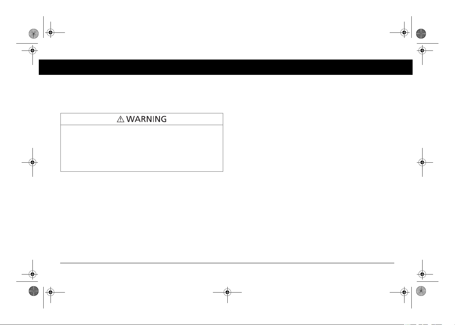
Failure to follow these instructions will result in death or serious
injury.
Failure to follow these instructions can result in death or serious
injury.
Failure to follow these instructions can result in minor or moderate
injury.
Failure to follow these instructions can damage the unit and/or
damage other equipment.
Freedom SW 3K2K InvChg Owners Guide.book Page ii Wednesday, October 9, 2013 1:34 PM
About This Guide
Purpose
The purpose of this Owner’s Guide is to provide explanations and
procedures for operating, troubleshooting, and maintaining the Freedom
SW Inverter/Charger.
Scope
The Guide provides safety and operating guidelines as well as information
on configuring the inverter/charger. It also provides information about
troubleshooting the unit. It does not provide details about particular brands
of batteries. You need to consult individual battery manufacturers for this
information.
Audience
The Guide is intended for users and operators of the Freedom SW Inverter/
Charger.
Conventions Used
The following conventions are used in this guide.
STATEMENT OF HAZARD
Contains statements of avoidance or strict compliance.
STATEMENT OF HAZARD
Contains statements of avoidance or strict compliance.
STATEMENT OF HAZARD
Contains statements of avoidance or strict compliance.
STATEMENT OF HAZARD
Contains statements of avoidance or strict compliance.
ii Freedom SW Owner’s Guide
IMPORTANT:
know, however, they are not as serious as a caution or warning.
These notes describe things which are important for you to
Page 5
Freedom SW 3K2K InvChg Owners Guide.book Page iii Wednesday, October 9, 2013 1:34 PM
Related Information
You can find more information about Xantrex-branded products and
services at www.xantrex.com.
NOTE: The Installation Guide (Document Part Number: 97-0020-01-01) is
primarily intended for qualified installers who need to install and configure
the Freedom SW Inverter/Charger. The installer should have knowledge
and experience in installing electrical equipment, knowledge of the
applicable installation codes, and awareness of the hazards involved in
performing electrical work and how to reduce those hazards. A qualified
technician or electrician has this knowledge and experience.
97-0019-01-01 iii
Page 6
Failure to follow these instructions will result in death or serious
injury.
Freedom SW 3K2K InvChg Owners Guide.book Page iv Wednesday, October 9, 2013 1:34 PM
Important Safety Instructions
IMPORTANT: READ AND SAVE THIS OWNER’S GUIDE FOR FUTURE
REFERENCE.
This chapter contains important safety and installation instructions for the
Freedom SW Inverter/Charger (Freedom SW). Each time, before using the
Freedom SW, READ ALL instructions and cautionary markings on or
provided with the inverter/charger, the batteries, and all appropriate sections
of this guide.
NOTE: The Freedom SW contains no user-serviceable parts.
ELECTRICAL SHOCK HAZARD
• Do not expose the Freedom SW to rain, snow, spray, or bilge water.
This inverter/charger is designed for marine applications only when
additional drip protection is installed in certain orientations. See the
installation guide for information.
• Do not operate the inverter/charger if it has received a sharp blow,
been dropped, has cracks or openings in the enclosure including if the
fuse cover has been lost, damaged, or will not close, or otherwise
damaged in any other way.
• Do not disassemble the inverter/charger. Internal capacitors remain
charged after all power is disconnected.
• Disconnect both AC and DC power from the inverter/charger before
attempting any maintenance or cleaning or working on any circuits
connected to the inverter/charger. See note below.
• Do not operate the inverter/charger with damaged or substandard
wiring. Make sure that all wiring is in good condition and is not
undersized.
NOTE: Turning off the inverter/charger using the on/off switch on the front
panel will not reduce an electrical shock hazard.
iv Freedom SW Owner’s Guide
Page 7
Failure to follow these instructions will result in death or serious
injury.
Failure to follow these instructions will result in death or serious
injury.
Freedom SW 3K2K InvChg Owners Guide.book Page v Wednesday, October 9, 2013 1:34 PM
FIRE AND BURN HAZARD
• Do not cover or obstruct the air intake vent openings and/or install in
a zero-clearance compartment.
• Do not use transformerless battery chargers in conjunction with the
inverter/charger due to overheating.
EXPLOSION HAZARD
• Charge only properly rated (such as 12 V) lead-acid (GEL, AGM,
Flooded, or lead-calcium) rechargeable batteries because other
battery types may explode.
• Do not work in the vicinity of lead-acid batteries. Batteries generate
explosive gases during normal operation. See note #1.
• Do not install and/or operate in compartments containing flammable
materials or in locations that require ignition-protected equipment.
See notes #2 and #3.
NOTES:
1. Follow these instructions and those published by the battery
manufacturer and the manufacturer of any equipment you intend to use
in the vicinity of the battery. Review cautionary markings on these
products and on the engine.
2. This inverter/charger contains components which tend to produce arcs
or sparks.
3. Locations include any space containing gasoline-powered machinery,
fuel tanks, as well as joints, fittings, or other connections between
components of the fuel system.
97-0019-01-01 v
Page 8
Failure to follow these instructions can result in death or serious
injury.
Freedom SW 3K2K InvChg Owners Guide.book Page vi Wednesday, October 9, 2013 1:34 PM
Precautions When Working With Batteries
BURN FROM HIGH SHORT-CIRCUIT CURRENT, FIRE AND EXPLOSION FROM VENTED GASES HAZARDS
• Always wear proper, non-absorbent gloves, complete eye protection,
and clothing protection. Avoid touching your eyes and wiping your
forehead while working near batteries. See note #4.
• Remove all personal metal items, like rings, bracelets, and watches
when working with batteries. See notes #5 and #6 below.
• Never smoke or allow a spark or flame near the engine or batteries.
• Never charge a frozen battery.
NOTES:
1. Mount and place the Freedom SW Inverter/Charger unit away from
batteries in a well ventilated compartment.
2. Always have someone within range of your voice or close enough to
come to your aid when you work near a lead-acid battery.
3. Always have plenty of fresh water and soap nearby in case battery acid
contacts skin, clothing, or eyes.
4. If battery acid contacts skin or clothing, wash immediately with soap
and water. If acid enters your eye, immediately flood it with running
cold water for at least twenty minutes and get medical attention
immediately.
5. Use extra caution to reduce the risk or dropping a metal tool on the
battery. It could spark or short circuit the battery or other electrical
parts and could cause an explosion.
6. Batteries can produce a short circuit current high enough to weld a ring
or metal bracelet or the like to the battery terminal, causing a severe
burn.
7. When removing a battery, always remove the negative terminal from
the battery first for systems with grounded negative. If it is grounded
positive, remove the positive terminal first. Make sure all loads
connected to the battery and all accessories are off so you don’t cause
an arc.
vi Freedom SW Owner’s Guide
Page 9
Failure to follow these instructions can result in death or serious
injury.
Failure to follow these instructions can result in death or serious
injury.
Freedom SW 3K2K InvChg Owners Guide.book Page vii Wednesday, October 9, 2013 1:34 PM
Precautions When Preparing to Charge
EXPOSURE TO CHEMICALS AND GASES HAZARD
• Make sure the area around the battery is well ventilated.
• Make sure the voltage of the batteries matches the output voltage of
the inverter/charger.
• Be careful to keep corrosion from coming into contact with your eyes
and skin when cleaning battery terminals.
NOTES:
• Study and follow all of the battery manufacturer's specific precautions,
such as removing or not removing cell caps while charging, whether
equalization is acceptable for your battery, and recommended rates of
charge.
• For flooded non-sealed batteries, add distilled water in each cell until
battery acid reaches the level specified by the battery manufacturer.
This helps to purge excessive gas from cells. Do not overfill. For a
battery without removable cell caps, carefully follow manufacturer's
instructions.
Regulatory
The Freedom SW Inverter/Charger is certified to appropriate US and
Canadian standards. For more information see “Regulatory Approvals” on
page 80.
The Freedom SW Inverter/Charger is intended to be used for mobile or
commercial applications. This inverter/charger is designed for marine
applications only when additional drip protection is installed in certain
orientations. See the installation guide for information.
It is not intended for other applications as it may not comply with the
additional safety code requirements needed for those other applications. See
“Limitations On Use” below.
LIMITATIONS ON USE
• Do not use in connection with life support systems or other medical
equipment or devices.
• Do not use in ambulances or other life-saving emergency vehicles.
97-0019-01-01 vii
Page 10

Freedom SW 3K2K InvChg Owners Guide.book Page viii Wednesday, October 9, 2013 1:34 PM
FCC Information to the User
This equipment has been tested and found to comply with the limits for a
Class B digital device, pursuant to part 15 of the FCC Rules. These limits
are designed to provide reasonable protection against harmful interference
in a residential installation. This equipment generates, uses, and can radiate
radio frequency energy and, if not installed and used in accordance with the
instructions, may cause harmful interference to radio communications.
However, there is no guarantee that interference will not occur in a
particular installation. If this equipment does cause harmful interference to
radio or television reception, which can be determined by turning the
equipment off and on, the user is encouraged to try to correct the
interference by one or more of the following measures:
• Reorient or relocate the receiving antenna.
• Increase the separation between the equipment and receiver.
• Connect the equipment into an outlet on a circuit different from that to
which the receiver is connected.
• Consult the dealer or an experienced radio/TV technician for help.
viii Freedom SW Owner’s Guide
Page 11
Freedom SW 3K2K InvChg Owners Guide.book Page i Wednesday, October 9, 2013 1:34 PM
Contents
Important Safety Instructions
Introduction . . . . . . . . . . . . . . . . . . . . . . . . . . . . . . . . . . . . . . . . . . . . . . . . . . . . . . . . . . . . . . . . . . . . . . . . . . . . . . . . . . . . . . . . . . . . . . . . . . . .1
Materials List . . . . . . . . . . . . . . . . . . . . . . . . . . . . . . . . . . . . . . . . . . . . . . . . . . . . . . . . . . . . . . . . . . . . . . . . . . . . . . . . . . . . . . . . . . .1
Key Features . . . . . . . . . . . . . . . . . . . . . . . . . . . . . . . . . . . . . . . . . . . . . . . . . . . . . . . . . . . . . . . . . . . . . . . . . . . . . . . . . . . . . . . . . . .2
Key Features Explained . . . . . . . . . . . . . . . . . . . . . . . . . . . . . . . . . . . . . . . . . . . . . . . . . . . . . . . . . . . . . . . . . . . . . . . . . . . . . . .2
Stacking . . . . . . . . . . . . . . . . . . . . . . . . . . . . . . . . . . . . . . . . . . . . . . . . . . . . . . . . . . . . . . . . . . . . . . . . . . . . . . . . . . . . . . . . . . .3
Stack Charging . . . . . . . . . . . . . . . . . . . . . . . . . . . . . . . . . . . . . . . . . . . . . . . . . . . . . . . . . . . . . . . . . . . . . . . . . . . . . . . . . . . . . .4
Generator Assist . . . . . . . . . . . . . . . . . . . . . . . . . . . . . . . . . . . . . . . . . . . . . . . . . . . . . . . . . . . . . . . . . . . . . . . . . . . . . . . . . . . . .4
Basic Protection Features . . . . . . . . . . . . . . . . . . . . . . . . . . . . . . . . . . . . . . . . . . . . . . . . . . . . . . . . . . . . . . . . . . . . . . . . . . . . . . . . . . 5
System Components . . . . . . . . . . . . . . . . . . . . . . . . . . . . . . . . . . . . . . . . . . . . . . . . . . . . . . . . . . . . . . . . . . . . . . . . . . . . . . . . . . . . . . . . . . . . .6
Xanbus System . . . . . . . . . . . . . . . . . . . . . . . . . . . . . . . . . . . . . . . . . . . . . . . . . . . . . . . . . . . . . . . . . . . . . . . . . . . . . . . . . . . . . . 6
Xanbus-enabled Products and Accessories . . . . . . . . . . . . . . . . . . . . . . . . . . . . . . . . . . . . . . . . . . . . . . . . . . . . . . . . . . . . . . . . . . . .7
Freedom SW Inverter/Charger Mechanical Features . . . . . . . . . . . . . . . . . . . . . . . . . . . . . . . . . . . . . . . . . . . . . . . . . . . . . . . . . . . . . . . . . . . . 8
Freedom SW Front and Side Panels . . . . . . . . . . . . . . . . . . . . . . . . . . . . . . . . . . . . . . . . . . . . . . . . . . . . . . . . . . . . . . . . . . . . . . . . .9
Freedom Inverter/Charger Operation . . . . . . . . . . . . . . . . . . . . . . . . . . . . . . . . . . . . . . . . . . . . . . . . . . . . . . . . . . . . . . . . . . . . . . . . . . . . . . . 11
Start Up Behavior . . . . . . . . . . . . . . . . . . . . . . . . . . . . . . . . . . . . . . . . . . . . . . . . . . . . . . . . . . . . . . . . . . . . . . . . . . . . . . . . . . . . . .11
Inverter Operation Using the Front Panel . . . . . . . . . . . . . . . . . . . . . . . . . . . . . . . . . . . . . . . . . . . . . . . . . . . . . . . . . . . . . . . . . . . . 12
Operating Limits for Inverter Operation . . . . . . . . . . . . . . . . . . . . . . . . . . . . . . . . . . . . . . . . . . . . . . . . . . . . . . . . . . . . . . . . . .13
Operating Limits for Charger Operation . . . . . . . . . . . . . . . . . . . . . . . . . . . . . . . . . . . . . . . . . . . . . . . . . . . . . . . . . . . . . . . . .14
Operating the Freedom SW with the SCP. . . . . . . . . . . . . . . . . . . . . . . . . . . . . . . . . . . . . . . . . . . . . . . . . . . . . . . . . . . . . . . . . . . . . . . . . . . .15
Using the Xanbus SCP . . . . . . . . . . . . . . . . . . . . . . . . . . . . . . . . . . . . . . . . . . . . . . . . . . . . . . . . . . . . . . . . . . . . . . . . . . . . . . . . . . . 16
System Control Panel . . . . . . . . . . . . . . . . . . . . . . . . . . . . . . . . . . . . . . . . . . . . . . . . . . . . . . . . . . . . . . . . . . . . . . . . . . . . . . . .16
. . . . . . . . . . . . . . . . . . . . . . . . . . . . . . . . . . . . . . . . . . . . . . . . . . . . . . . . . . . . . . . . . . . . . . . . . . . . . . iv
Page 12

Freedom SW 3K2K InvChg Owners Guide.book Page ii Wednesday, October 9, 2013 1:34 PM
SCP Navigation . . . . . . . . . . . . . . . . . . . . . . . . . . . . . . . . . . . . . . . . . . . . . . . . . . . . . . . . . . . . . . . . . . . . . . . . . . . . . . . . . . . . . . . .18
Startup Screen . . . . . . . . . . . . . . . . . . . . . . . . . . . . . . . . . . . . . . . . . . . . . . . . . . . . . . . . . . . . . . . . . . . . . . . . . . . . . . . . . . . . . .18
Viewing the SCP Home Screens . . . . . . . . . . . . . . . . . . . . . . . . . . . . . . . . . . . . . . . . . . . . . . . . . . . . . . . . . . . . . . . . . . . . . . .18
Soft Key Navigation . . . . . . . . . . . . . . . . . . . . . . . . . . . . . . . . . . . . . . . . . . . . . . . . . . . . . . . . . . . . . . . . . . . . . . . . . . . . . . . . .20
Viewing the Firmware Revision Number . . . . . . . . . . . . . . . . . . . . . . . . . . . . . . . . . . . . . . . . . . . . . . . . . . . . . . . . . . . . . . . . . . . .22
Setting the Time and Date . . . . . . . . . . . . . . . . . . . . . . . . . . . . . . . . . . . . . . . . . . . . . . . . . . . . . . . . . . . . . . . . . . . . . . . . . . . . . . . .23
Using the STBY/ON Fault Clear Button . . . . . . . . . . . . . . . . . . . . . . . . . . . . . . . . . . . . . . . . . . . . . . . . . . . . . . . . . . . . . . . . . . . . .23
Reading the System Status Screen . . . . . . . . . . . . . . . . . . . . . . . . . . . . . . . . . . . . . . . . . . . . . . . . . . . . . . . . . . . . . . . . . . . . . . . . . .24
Reading the Freedom SW Device Setup Screen . . . . . . . . . . . . . . . . . . . . . . . . . . . . . . . . . . . . . . . . . . . . . . . . . . . . . . . . . . . . . . . 25
Configuring the Freedom SW using the SCP . . . . . . . . . . . . . . . . . . . . . . . . . . . . . . . . . . . . . . . . . . . . . . . . . . . . . . . . . . . . . . . . . . . . . . . . . 28
System Menu Map . . . . . . . . . . . . . . . . . . . . . . . . . . . . . . . . . . . . . . . . . . . . . . . . . . . . . . . . . . . . . . . . . . . . . . . . . . . . . . . . . . . . . .29
Viewing the System Status Screen . . . . . . . . . . . . . . . . . . . . . . . . . . . . . . . . . . . . . . . . . . . . . . . . . . . . . . . . . . . . . . . . . . . . . .30
Viewing the Select Device Menu . . . . . . . . . . . . . . . . . . . . . . . . . . . . . . . . . . . . . . . . . . . . . . . . . . . . . . . . . . . . . . . . . . . . . . .30
Selecting the Freedom SW from the Select Device Menu . . . . . . . . . . . . . . . . . . . . . . . . . . . . . . . . . . . . . . . . . . . . . . . . . . . .31
Changing Configurable Settings From The Device Setup Menu Screen . . . . . . . . . . . . . . . . . . . . . . . . . . . . . . . . . . . . . . . . . . . .32
Using Search Mode . . . . . . . . . . . . . . . . . . . . . . . . . . . . . . . . . . . . . . . . . . . . . . . . . . . . . . . . . . . . . . . . . . . . . . . . . . . . . . . . . .34
Equalization Procedure . . . . . . . . . . . . . . . . . . . . . . . . . . . . . . . . . . . . . . . . . . . . . . . . . . . . . . . . . . . . . . . . . . . . . . . . . . . . . . .36
Changing Freedom SW Basic Settings . . . . . . . . . . . . . . . . . . . . . . . . . . . . . . . . . . . . . . . . . . . . . . . . . . . . . . . . . . . . . . . . . . . . . . 37
Charger settings in a Dual Freedom SW configuration . . . . . . . . . . . . . . . . . . . . . . . . . . . . . . . . . . . . . . . . . . . . . . . . . . . . . . . . .40
Calculations . . . . . . . . . . . . . . . . . . . . . . . . . . . . . . . . . . . . . . . . . . . . . . . . . . . . . . . . . . . . . . . . . . . . . . . . . . . . . . . . . . . . . . . 40
Examples . . . . . . . . . . . . . . . . . . . . . . . . . . . . . . . . . . . . . . . . . . . . . . . . . . . . . . . . . . . . . . . . . . . . . . . . . . . . . . . . . . . . . . . . . .40
Changing Freedom SW Advanced Settings . . . . . . . . . . . . . . . . . . . . . . . . . . . . . . . . . . . . . . . . . . . . . . . . . . . . . . . . . . . . . . . . . . .41
Inverter Settings Menu . . . . . . . . . . . . . . . . . . . . . . . . . . . . . . . . . . . . . . . . . . . . . . . . . . . . . . . . . . . . . . . . . . . . . . . . . . . . . . . . . . .46
Using the Low Battery Cut Out and LBCO Delay Settings . . . . . . . . . . . . . . . . . . . . . . . . . . . . . . . . . . . . . . . . . . . . . . . . . . . 47
Charger Settings Menu . . . . . . . . . . . . . . . . . . . . . . . . . . . . . . . . . . . . . . . . . . . . . . . . . . . . . . . . . . . . . . . . . . . . . . . . . . . . . . . . . .48
Battery Charger Functions . . . . . . . . . . . . . . . . . . . . . . . . . . . . . . . . . . . . . . . . . . . . . . . . . . . . . . . . . . . . . . . . . . . . . . . . . . . .49
Custom Battery Settings Menu . . . . . . . . . . . . . . . . . . . . . . . . . . . . . . . . . . . . . . . . . . . . . . . . . . . . . . . . . . . . . . . . . . . . . . . . .50
Page 13
Freedom SW 3K2K InvChg Owners Guide.book Page iii Wednesday, October 9, 2013 1:34 PM
ACIn Settings . . . . . . . . . . . . . . . . . . . . . . . . . . . . . . . . . . . . . . . . . . . . . . . . . . . . . . . . . . . . . . . . . . . . . . . . . . . . . . . . . . . . . . . . . . 52
Gen Support . . . . . . . . . . . . . . . . . . . . . . . . . . . . . . . . . . . . . . . . . . . . . . . . . . . . . . . . . . . . . . . . . . . . . . . . . . . . . . . . . . . . . . . . . . .53
Stacking Configuration Menu . . . . . . . . . . . . . . . . . . . . . . . . . . . . . . . . . . . . . . . . . . . . . . . . . . . . . . . . . . . . . . . . . . . . . . . . . . . . .54
Setting the Device Name . . . . . . . . . . . . . . . . . . . . . . . . . . . . . . . . . . . . . . . . . . . . . . . . . . . . . . . . . . . . . . . . . . . . . . . . . . . . .55
Setting the Device Number . . . . . . . . . . . . . . . . . . . . . . . . . . . . . . . . . . . . . . . . . . . . . . . . . . . . . . . . . . . . . . . . . . . . . . . . . . . . 56
Resetting the Freedom SW to Default Settings . . . . . . . . . . . . . . . . . . . . . . . . . . . . . . . . . . . . . . . . . . . . . . . . . . . . . . . . . . . . . . . .57
Using the Advanced Features . . . . . . . . . . . . . . . . . . . . . . . . . . . . . . . . . . . . . . . . . . . . . . . . . . . . . . . . . . . . . . . . . . . . . . . . . . . . .57
Battery Charging Reference . . . . . . . . . . . . . . . . . . . . . . . . . . . . . . . . . . . . . . . . . . . . . . . . . . . . . . . . . . . . . . . . . . . . . . . . . . . . . . . . . . . . . .58
Battery Types . . . . . . . . . . . . . . . . . . . . . . . . . . . . . . . . . . . . . . . . . . . . . . . . . . . . . . . . . . . . . . . . . . . . . . . . . . . . . . . . . . . . . . . . . .58
Charge Algorithm Stages . . . . . . . . . . . . . . . . . . . . . . . . . . . . . . . . . . . . . . . . . . . . . . . . . . . . . . . . . . . . . . . . . . . . . . . . . . . . . . . . .58
Three-Stage charging . . . . . . . . . . . . . . . . . . . . . . . . . . . . . . . . . . . . . . . . . . . . . . . . . . . . . . . . . . . . . . . . . . . . . . . . . . . . . . . .58
Two-Stage Charging Process . . . . . . . . . . . . . . . . . . . . . . . . . . . . . . . . . . . . . . . . . . . . . . . . . . . . . . . . . . . . . . . . . . . . . . . . . .61
Equalize Charging . . . . . . . . . . . . . . . . . . . . . . . . . . . . . . . . . . . . . . . . . . . . . . . . . . . . . . . . . . . . . . . . . . . . . . . . . . . . . . . . . . . . . .63
Troubleshooting. . . . . . . . . . . . . . . . . . . . . . . . . . . . . . . . . . . . . . . . . . . . . . . . . . . . . . . . . . . . . . . . . . . . . . . . . . . . . . . . . . . . . . . . . . . . . . . . 65
General Troubleshooting Guidelines . . . . . . . . . . . . . . . . . . . . . . . . . . . . . . . . . . . . . . . . . . . . . . . . . . . . . . . . . . . . . . . . . . . . . . . .65
Inverter Applications . . . . . . . . . . . . . . . . . . . . . . . . . . . . . . . . . . . . . . . . . . . . . . . . . . . . . . . . . . . . . . . . . . . . . . . . . . . . . . . . . . . .66
Resistive Loads . . . . . . . . . . . . . . . . . . . . . . . . . . . . . . . . . . . . . . . . . . . . . . . . . . . . . . . . . . . . . . . . . . . . . . . . . . . . . . . . . . . . .66
Motor Loads . . . . . . . . . . . . . . . . . . . . . . . . . . . . . . . . . . . . . . . . . . . . . . . . . . . . . . . . . . . . . . . . . . . . . . . . . . . . . . . . . . . . . . .66
Problem Loads . . . . . . . . . . . . . . . . . . . . . . . . . . . . . . . . . . . . . . . . . . . . . . . . . . . . . . . . . . . . . . . . . . . . . . . . . . . . . . . . . . . . .66
Fault Types . . . . . . . . . . . . . . . . . . . . . . . . . . . . . . . . . . . . . . . . . . . . . . . . . . . . . . . . . . . . . . . . . . . . . . . . . . . . . . . . . . . . . . . . . . . .67
Troubleshooting the Freedom SW via the SCP . . . . . . . . . . . . . . . . . . . . . . . . . . . . . . . . . . . . . . . . . . . . . . . . . . . . . . . . . . . . . . . .68
Fault Types . . . . . . . . . . . . . . . . . . . . . . . . . . . . . . . . . . . . . . . . . . . . . . . . . . . . . . . . . . . . . . . . . . . . . . . . . . . . . . . . . . . . . . . .68
Warning Types . . . . . . . . . . . . . . . . . . . . . . . . . . . . . . . . . . . . . . . . . . . . . . . . . . . . . . . . . . . . . . . . . . . . . . . . . . . . . . . . . . . . .69
Specifications . . . . . . . . . . . . . . . . . . . . . . . . . . . . . . . . . . . . . . . . . . . . . . . . . . . . . . . . . . . . . . . . . . . . . . . . . . . . . . . . . . . . . . . . . . . . . . . . .77
Page 14

Freedom SW 3K2K InvChg Owners Guide.book Page iv Wednesday, October 9, 2013 1:34 PM
Page 15
FREEDOM SW
3012
FREEDOM
SW
3012
CLEAR FAULT
RESET
INVERTER
ENABLE
INVERTER
ENABLED
AC IN
FAULT
GEN
SUPPORT
CHARGING
WARNING
BTS
DC terminal covers
with screws
nuts and washers
Freedom SW 3012 shown
Installation and
Owner’s Guides
Xanbus network
terminators
Freedom SW 3K2K InvChg Owners Guide.book Page 1 Wednesday, October 9, 2013 1:34 PM
Introduction
Congratulations on your purchase of the Freedom SW Inverter/Charger
(Freedom SW). The Freedom SW has been designed to give you premium
power, ease of use, and outstanding reliability.
Please read this chapter to familiarize yourself with the main performance
and protection features of the Freedom SW.
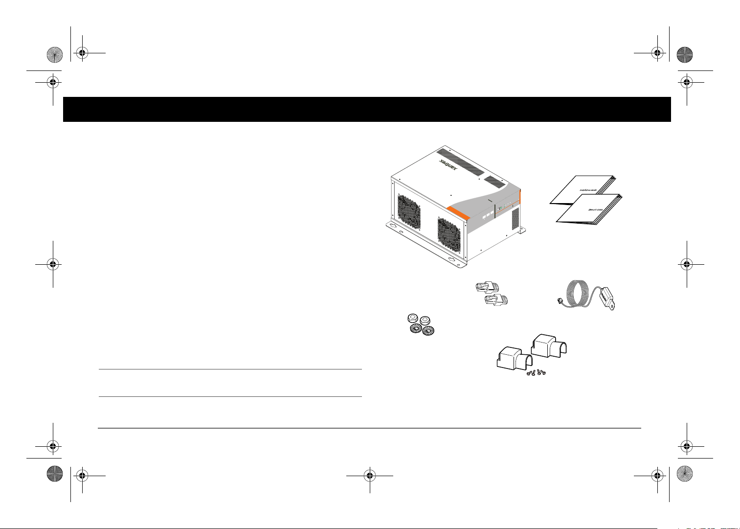
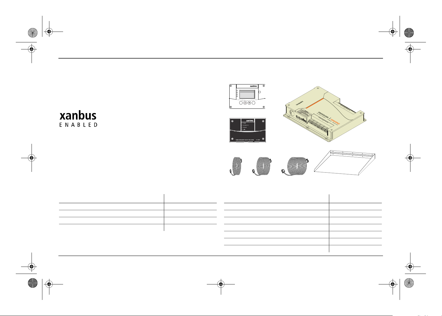
Materials List
The Freedom SW ships with the following items:
• one Freedom SW unit
• owner’s and installation guides
• Battery Temperature Sensor (BTS)
• DC terminal covers (one red, one black) with two sets of screws
• two Xanbus network terminators
• two sets of nuts and washers for the DC terminals
NOTE: If any of the items are missing, contact customer service or any
authorized Xantrex dealer for replacement. See “About This Guide” on
page ii.
IMPORTANT:
return the Freedom SW for servicing.
Keep the carton and packing material in case you need to
Figure 1
97-0019-01-01 1
Materials List
Page 16

Freedom SW 3K2K InvChg Owners Guide.book Page 2 Wednesday, October 9, 2013 1:34 PM
Introduction
Key Features
The Freedom SW Inverter/Charger is a true sine wave inverter/charger that
can be used for mobile, marine and commercial applications. The Freedom
SW Inverter/Chargers are designed to operate with a wide variety of
generators and are capable of operating in parallel with a generator for short
durations to assist with starting large loads. The Freedom SW is a
convenient combination of an inverter, multistage battery charger, and
transfer switch in one electronic device.
• As an inverter, the Freedom SW provides true sine wave power for
your microwave, entertainment system, computer, and other loads.
This power is identical to the AC source provided from the utility grid
(power company).
• Some of the benefits of true sine wave power include consistent
cooking in your microwave, handling of sensitive loads such as your
TV set, dimmer switches, and appliances with speed controls.
• Highly versatile platform capable of series stacking for 120/240V line
configurations and parallel stacking to increase power levels.
• High efficiency true sine wave output to power sensitive electrical and
electronic equipment.
• Surge capacity to start difficult loads like well pumps, refrigerators, or
A/C compressors.
• Power factor-corrected (PFC) input minimizes AC input current
required for charging, increasing AC pass-through capacity.
• As a charger, it has high output, multi-stage charging capability
minimizing charging time.
• Capable of operating from 50Hz and 60Hz power source by extending
AC qualification frequency range. See “ACIn Settings” on page 52.
IMPORTANT: Dual Line models require only the Line 1 Input to be
energized in order to qualify AC. Line 2 Input does not have to be
powered in a single phase system.
• Temperature-controlled, variable-speed internal cooling fans. The fans
turn on when the internal temperature reaches 45 °C (113 °F) and
reaches maximum speed at 70 °C (158 °F). The fan turns off when the
internal temperature falls to 40 °C (104 °F).
• Designed with efficient field serviceability in mind.
• The Freedom SW Inverter/Charger is also Xanbus-enabled which
allows network compatibility and communication with other Xanbusenabled devices. See more information under “System Components”
on page 6.
Key Features Explained
Built-in Charge Formulas For the unit to perform at the highest level,
the batteries must be charged correctly. The Freedom SW has optimized
algorithms for flooded, gel, and AGM batteries.
Battery Temperature Sensor Since battery temperature is a key factor in
correct charging, the charging formula must be adjusted (automatically and
in real time) according to the actual battery temperature to ensure that
batteries are fully charged, but not overcharged. For this reason, a battery
temperature sensor is included with your Freedom SW and has temperature
compensated the charge formula.
2 Freedom SW Owner’s Guide
Page 17
Freedom SW 3K2K InvChg Owners Guide.book Page 3 Wednesday, October 9, 2013 1:34 PM
Manual Equalization Over a period of time, the cells in a flooded
battery can develop uneven chemical states. This can result in a weak
(undercharged) cell which, in turn, can reduce the overall capacity of the
battery. To improve the life and performance of a non-sealed, flooded
battery, the Freedom SW’s multi-stage charging cycle includes a manual
equalize mode that can be used, if recommended by the battery
manufacturer.
Dead Battery Charging Another feature that the Freedom SW includes
is dead battery charging. The Freedom SW—unlike many chargers—has
the ability to recharge batteries even if the battery voltage is very low, i.e.,
as low as 3 volts.
Load Management The Freedom SW has a built-in transfer relay that
connects your inverter output or AC input from the utility grid or generator
to your loads. Because the usual AC power sources such as campground
outlets or small generators often have limited current availability, having
the capability to manage your AC loads is extremely valuable. The
Freedom SW provides a number of features to facilitate this:
• The charger is power factor corrected to use AC current as efficiently
as possible. Minimizing the AC current used by the charger means
more current is available for your AC loads.
• Freedom SW has a power share feature which prioritizes your AC
loads by reducing the charge current and maintaining the total input
current to less than the breaker setting.
Occasionally, AC input sources have low voltage. To avoid loading these
weak sources any further, the charger automatically reduces its AC current
draw as the AC voltage approaches the minimum acceptable level.
Introduction
Stacking
Supports stacking of two inverter/chargers to increase capacity. This also
requires the installer to select a Master and Slave in order for the inverters
to stack. Two configurations of stacking are supported: Parallel stacking
and Series stacking.
Parallel Stacking
Parallel stacking allows two inverter/chargers to operate in parallel thereby
doubling the capacity in inverter mode. The two inverters communicate
over the network and intelligently share the load and to balance the load
between the two units. The Master Freedom SW broadcasts pulses on the
Xanbus network to synchronize operation between the other paralleled unit.
When AC loads are present, both units produce power, effectively sharing
the load. When Search mode is enabled, only the Master unit produces the
AC output.
Series Stacking
Two units can be configured to generate 120/240 Split-phase power for load
configurations that require both 120 and 240 volts. In this configuration, the
AC source must be split-phase as well.
97-0019-01-01 3
Page 18
Freedom SW 3K2K InvChg Owners Guide.book Page 4 Wednesday, October 9, 2013 1:34 PM
Introduction
Stack Charging
Multiple Freedom SWs synchronize charging stages to ensure efficient
charging of the battery bank. When a single unit transitions from bulk to
absorption so do all other units. In absorption, all units must complete the
absorption stage before transitioning to the next stage. Note that units do
not load share when charging except during the bulk stage. The Freedom
SWs stop sharing charge current just before completing the bulk stage. The
units do not share charge current during the absorption and float stages.
Each unit charges batteries based on the Max Charge Rate setting and active
internal (temperature-based) deratings.
If equalization is enabled on one or more devices capable of equalization
charging, only those devices perform an equalize cycle after absorption.
Other devices transition to float (if three-stage charging is selected) or
transition to AC pass-through (if two-stage charging is selected).
Generator Assist
The Freedom SW Series of inverter/chargers can operate in tandem with a
generator to temporarily assist power loads with large start-up demands
such as air conditioners, water pumps etc. A Xanbus AGS must be installed
in the system in order for this feature work.
When this mode is enabled and generator capacity defined, the inverter will
come on-line and assist the generator when the generator reaches its
capacity. The battery bank must be well charged in order for the inverter to
engage this mode. For more details, see “Gen Support” on page 53.
4 Freedom SW Owner’s Guide
Page 19
Freedom SW 3K2K InvChg Owners Guide.book Page 5 Wednesday, October 9, 2013 1:34 PM
Basic Protection Features
The Freedom SW has the following protection features:
• over temperature shutdown for critical components such as the
transformer and the power board
• battery temperature sensor (BTS) failure/battery temperature out-ofrange fault protection
• DC output over voltage protection during charge mode,
• AC transfer relay failure detection
• AC output overload and short circuit protection during invert mode
• AC backfeed
• short circuit protection for the BTS and communication connector
ports including protection from incorrectly inserting the remote panel
communication cable plug into the BTS port and vice versa
1
protection
Introduction
The Battery Temperature Sensor (BTS) provides these protection features:
• battery over temperature charging protection preventing battery
charging at 60 °C (140 °F) or higher
• charging voltage compensation based on the temperature of the battery
the BTS is connected to
1.An AC backfeed error occurs when the AC output of the inverter/charger is connected or routed back to the inverter/charger’s AC input terminal or if the internal
transfer relay fails.
97-0019-01-01 5
Page 20
Freedom SW 3K2K InvChg Owners Guide.book Page 6 Wednesday, October 9, 2013 1:34 PM
System Components
The Freedom SW uses Xanbus, a network communications protocol
developed to communicate the Freedom SW’s settings and activity to other
Xanbus-enabled devices.
You can configure and monitor the Freedom SW and every Xanbus-enabled
device in the system using an optional Xanbus System Control Panel (SCP).
Another component is the optional Xanbus Automatic Generator Start
(AGS) which allows operation with a wide range of generators, supported
through a dedicated generator input. Simply, the AGS automatically starts
and stops your generator.
The Freedom Sequence Intelligent Power Manager is a fully integrated
power management system that provides automatic power and load
management for use in recreational vehicles (RV) while receiving power
from a generator or shore power. This device works in the background to
prevent monitored AC loads from exceeding shore and generator breaker
capacity.
See “Xanbus-enabled Products and Accessories” on page 7 for part
numbers.
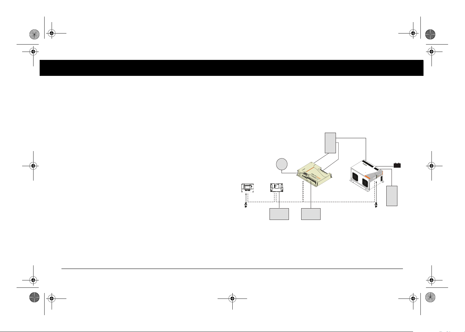
Xanbus System
The Xanbus system includes the Freedom SW and other Xanbus-enabled
devices. The Freedom SW is the device in a Xanbus system that typically
provides network power—500 mA at 12 volts DC. All of the Xanbusenabled devices, such as the Freedom SW, the SCP, and the AGS are able to
communicate their settings and activity to each other. See Figure 1.
AC Panel
Shore
Power
System Control Panel
Xanbus System Control Panel
network terminator network terminator
Figure 1
Automatic Generator Start
Xanbus Automatic Generator Start
Generator
Typical Xanbus System Diagram
Freedom Sequence
AC Loads
Freedom SW Inverter/Charger
FREEDOMSW
BATTERY
3012
lt
au
/
F
C
e
g
r
er A
t
ha
r
C
nve
I
On
r
e
t
r
e
v
n
I
3012
Enable
set
e
R
SW
FREEDOM
Inverter
Load Panel
6 Freedom SW Owner’s Guide
Page 21
XanbusSystem C ontrol Panel (SCP)
FGA:809-092 1
ACIn/Charge
InverterOn
LowBattery
Fault
STBY/ON
Fault Clea r
TM
Enter Func
Freedom
Sequence
SCP
AGS
25-ft cable 75-ft cable3-ft cable
Inverter drip shield
Freedom SW 3K2K InvChg Owners Guide.book Page 7 Wednesday, October 9, 2013 1:34 PM
The Xanbus-enabled designation (see below) means that this product works
on a Xanbus network. Xanbus-enabled products are:
• Simple to operate and routine tasks are automated.
• Controlled by software that eliminates analog signalling errors.
• Less susceptible to interference and line loss.
• Upgradable through new software releases.
For detailed instructions and a complete list of Xanbus-enabled devices,
visit www.xantrex.com.
System Components
Xanbus-enabled Products and Accessories
Product/Accessory (Not Shown) Product Number/s
Freedom SW On/Off Switch 808-9002
GFCI receptacles 808-9003
Drip shields 808-9004
Stacking cable 808-9005
Product/Accessory (Shown above) Product Number/s
Freedom Sequence Intelligent Power Manager 809-0912 / 809-0913
Xanbus System Control Panel (SCP) 809-0921
Xanbus Automatic Generator Start (AGS) 809-0915
3-ft network cable (0.9 m) 809-0935
25-ft network cable (7.6 m) 809-0940
75-ft network cable (22.9 m) 809-0942
Inverter drip shield 808-9004
97-0019-01-01 7
Page 22
FREEDOM
SW
3012
FREEDOM SW
3012
FREEDOM
SW
3012
FREEDOM SW
3012
CLEAR FAULT
RESET
INVERTER
ENABLE
INVERTER
ENABLED AC IN
FAULT
GEN
SUPPORT
CHARGING
WARNING
CLEAR FAULT
RESET
INVERTER
ENABLE
INVERTER
ENABLED
AC IN
FAULT
GEN
SUPPORT
CHARGING
WARNING
AC
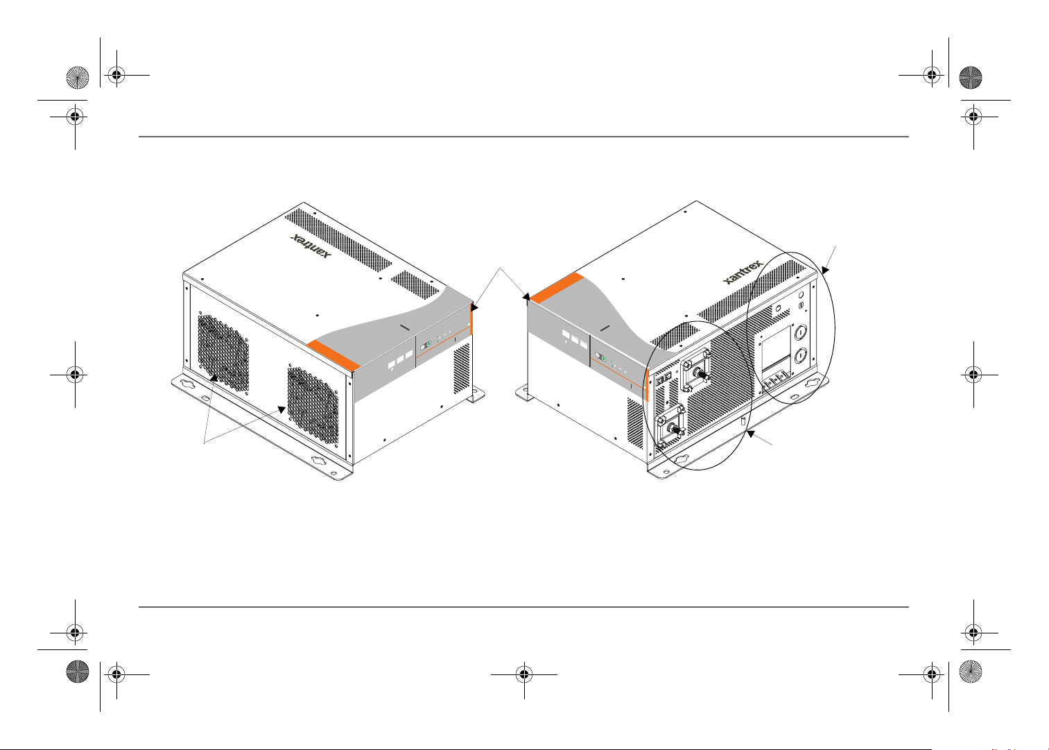
Cooling Fans
Front Panel
Controls and
Status LEDs
DC Terminal Side
Compartment
Side
and Ground Terminal Stud
Freedom SW 3K2K InvChg Owners Guide.book Page 8 Wednesday, October 9, 2013 1:34 PM
Freedom SW Inverter/Charger Mechanical Features
Freedom SW Inverter/Charger Mechanical Features
Figure 2
Freedom SW Front and Side Panels (Freedom SW 3012 shown)
8 Freedom SW Owner’s Guide
Page 23
2
1
3
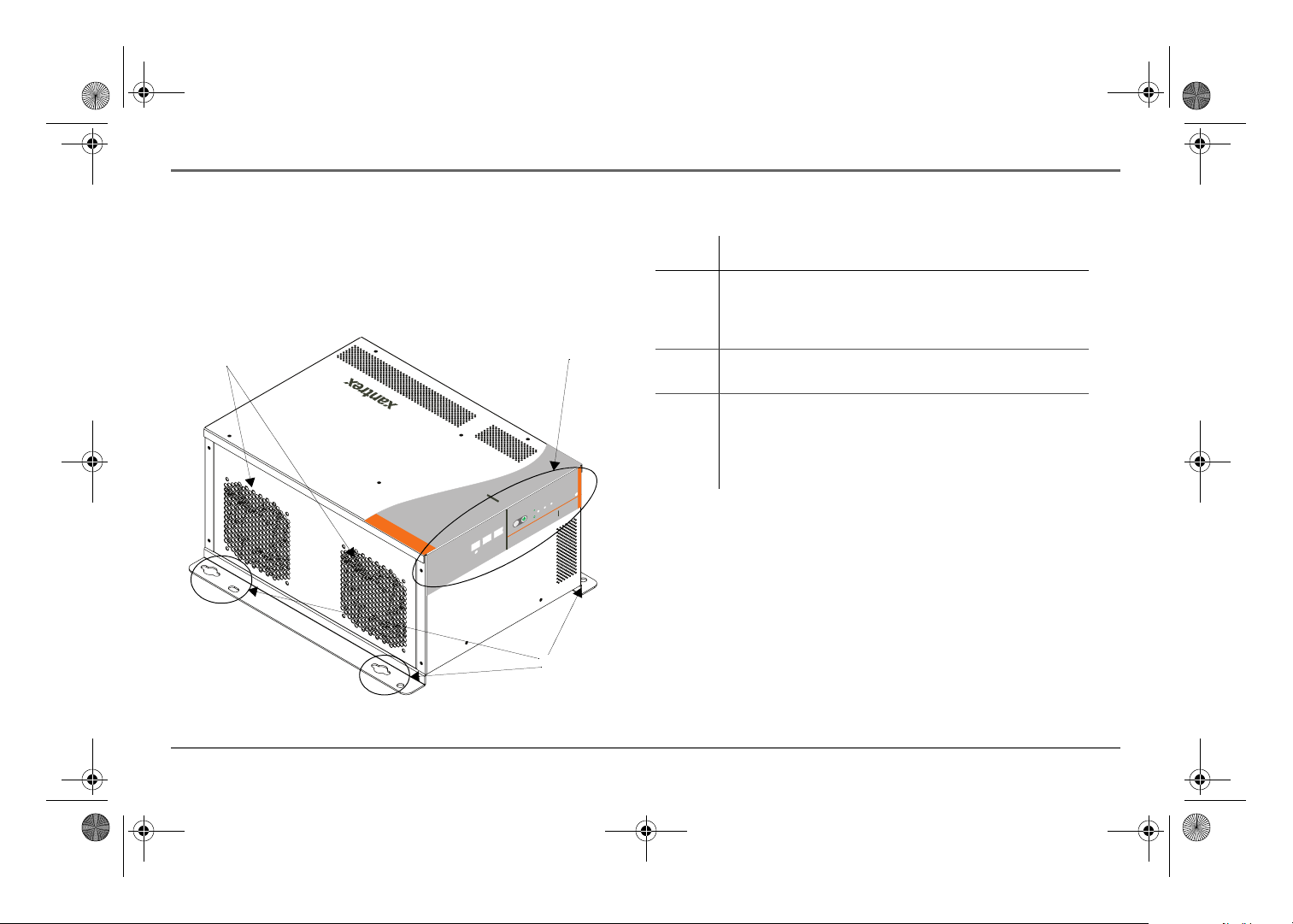
Freedom SW 3K2K InvChg Owners Guide.book Page 9 Wednesday, October 9, 2013 1:34 PM
Freedom SW Front and Side Panels
Before you begin to operate the Freedom SW, review the front panel
features shown in Figure 3 and described in the next table. A detailed view
of the lights and buttons on the front panel is shown in Figure 4 and
described in the table next to it.
3012
FAULT
AC IN
WARNING
FREEDOM SW
INVERTER
ENABLED
CHARGING
INVERTER
3012
GEN
ENABLE
SUPPORT
RESET
CLEAR FAULT
SW
FREEDOM
Freedom SW Inverter/Charger Mechanical Features
Item Description
1 Front Panel contains the Xanbus interface ports for connecting
Xanbus-enabled devices, the INVERTER ENABLE and CLEAR
FAU LT R ES ET buttons, as well as various LED status lights.
See Figure 4.
2 Mounting holes are used for mounting the unit. A total of eight
holes are provided on the unit.
3 Two variable-speed cooling fans are used to cool the unit. Fan
speed control is based on internal temperature of critical
components. The two exhaust fans control airflow though the
transformer and power compartments of the unit. Ensure at least
six inches of clearance for proper ventilation.
Figure 3
Isometric View of the Front Panel and Fans
97-0019-01-01 9
Page 24

XANBUS INTERFACE STACKING
FREEDOM SW INVERTER/CHARGER
CLEAR FAULT
RESET
INVERTER
ENABLE
INVERTER
ENABLED
AC IN FAULT
GEN
SUPPORT
CHARGING WARNING
314256
79 8
Freedom SW 3K2K InvChg Owners Guide.book Page 10 Wednesday, October 9, 2013 1:34 PM
Freedom SW Inverter/Charger Mechanical Features
FREEDOM SW
3012
CLEAR FAULT
RESET
INVERTER
ENABLE
INVERTER
ENABLED
AC IN
GEN
SUPPORT
FAULT
CHARGINGWARNING
FREEDOM
SW
3012
Item Description
1 DC terminals.
2 AC wiring compartment access panel with compartment cover on.
3 FAULT LED illuminates solid if a fault condition occurs and flashes
intermittently when a WARNING condition is active.
4 When AC is present and qualified, the AC IN LED will illuminate solid
indicating also that AC is passing through.
CHARGING LED flashes intermittently when the Freedom SW is in
charge mode and is producing DC output to charge your batteries.
5 INVERTER ENABLED indicates the invert mode is enabled. This is
different from the inverter being “on”. When enabled the inverter can
be on or off. When disabled, the inverter is always off. If AC is present
and invert mode is enabled, this LED remains illuminated even though
AC power is being passed through.
GEN SUPPORT LED flashes intermittently when the inverter is in
generator support mode and is assisting the generator.
6 INVERTER ENABLE button is used to enable or disable the inverter.
7 CLEAR FAULT RESET button is used to clear any active faults if pressed
momentarily. If held down for more than three seconds, the unit will
reset (reboot) itself.
8 STACKING port is used to connect two inverter/chargers together for
stacked operation. This is required only for stacking in series.
9 XANBUS INTERFACE ports are used to connect Xanbus-enabled
devices including the optional SCP and AGS.
Figure 4
10 Freedom SW Owner’s Guide
Isometric View of the Front Panel and AC/DC Side Panel
Page 25
Freedom SW 3K2K InvChg Owners Guide.book Page 11 Wednesday, October 9, 2013 1:34 PM
Freedom Inverter/Charger Operation
Start Up Behavior
When the Freedom SW is powered up or has been reset, all of the front
panel lights illuminate and remain on for a minimum of five seconds.
During this interval, the fans are also turned on as the unit executes internal
diagnostics.
The Freedom SW inverter is disabled every time the Freedom SW is
powered up. After power up, the INVERTER ENABLE button (or the SCP)
can be used to enable or disable the inverter.
When a function is enabled, it is allowed to occur but other conditions may
have to be met before the function is activated or turned on. For example,
the charger function on the Freedom SW may be enabled, but it will not
charge unless qualified AC power is present.
IMPORTANT:
before operating the inverter/charger.
Review the “Important Safety Instructions” on page iv
97-0019-01-01 11
Page 26
Freedom SW 3K2K InvChg Owners Guide.book Page 12 Wednesday, October 9, 2013 1:34 PM
Freedom Inverter/Charger Operation
Inverter Operation Using the Front Panel
IMPORTANT:
Review the “Important Safety Instructions” on page iv
before operating the inverter/charger.
Once the inverter/charger is installed, you can operate it in invert mode.
To operate in invert mode from the front panel:
1. Press the INVERTER ENABLE button on the Freedom SW on the front
panel. The INVERTER ENABLED LED illuminates and connected loads
will be energized.
2. Note that if AC is present and being passed through, the INVERTER
ENABLED LED will still illuminate to indicate inverter mode has been
enabled. However, AC will continue to be passed through to the loads
until conditions exist that cause AC to be disqualified, in which case
the unit will transition to invert mode and power up critical loads.
3. Connect AC input power.
The charger automatically starts up when qualified AC power is
connected.
To operate the inverter with the System Control Panel, refer to
“Operating the Freedom SW with the SCP” on page 15.
4. Disconnect AC power from inverter input by opening the breaker or
disconnect.
5. Place a load on the inverter. For example, plug a 100-watt light bulb
into an outlet that the inverter is powering. Press the INVERTER
ENABLE button on the Freedom SW. The INVERTER ENABLED LED
illuminates. The inverter should run the load using battery power.
6. To test the charger, reconnect the AC input power to allow AC to the
AC input. The AC/Charger On LED should start flashing after a brief
delay. Any AC loads previously powered by the inverter will also
work at this time.
NOTE: On dual input models, only AC Input L1 needs to be powered
for the unit to operate.
7. Remove the AC input power. The inverter/charger should transfer to
invert mode immediately. (The transfer relay will make a clicking
sound and the INVERTER ENABLED LED will illuminate.) Loads
should continue to operate uninterrupted.
If any part of this test fails, determine the cause before using the unit.
8. Monitor the Freedom SW Front Panel.
The indicator lights on the front panel show you the operating status of
the Freedom SW. A description of the lights is provided in Table 1.
If none of the front panel lights are on, see “Troubleshooting” on page
65.
Table 1
Front Panel Lights
Light
Illuminated Color Status Action (or Status Item)
INVERTER
ENABLED
GEN SUPPORT Flashing
Steady
Green
Green
If utility and generator AC is
unavailable and operating
conditions are met, the
Freedom SW will produce
AC voltage to power loads.
The inverter is assisting a
generator in powering loads.
You can run your appliances
from the inverter.
You can run your appliances
from the inverter.
12 Freedom SW Owner’s Guide
Page 27
Freedom SW 3K2K InvChg Owners Guide.book Page 13 Wednesday, October 9, 2013 1:34 PM
Table 1
Front Panel Lights
Light
Illuminated Color Status Action (or Status Item)
AC IN Steady
CHARGING Flashing
FAULT Steady
WARNING Flashing
Green
Green
Red
Red
When the Freedom SW is
connected to a qualified AC
source or a generator, the
External AC light
illuminates.
Freedom SW is connected to
a qualified AC source, is
charging and passing power
to AC loads.
A fault has occurred on the
network.
A warning is detected. Investigate by examining
You can run your appliances
from an AC source like the
utility grid or a generator.
Your battery bank is being
replenished and AC loads are
receiving power.
Investigate and clear the fault
condition.
warning logs on SCP.
Faults and Warnings A fault affects the operation of the unit. A manual
fault requires user intervention by clearing the condition and then pressing
the CLEAR FAULT RESET button on the inverter/charger’s front panel. See the
Xanbus System Control Panel Owner’s Guide for information on clearing
faults from the SCP.
A warning alerts you to a condition that could possibly affect operation of
the unit.
IMPORTANT:
If you are having problems with any of your loads, refer to
“Inverter Applications” on page 66.
Freedom Inverter/Charger Operation
Operating Limits for Inverter Operation
Temperature The Freedom SW series of inverter/chargers will operate at
rated power continuously at 30 °C with some models capable of continuous
operation at much higher ambient temperature. However, the continuous
power rating at elevated ambient temperature may differ between models.
See “Specifications” on page 77 for full details. In higher ambient
temperatures, if the loads draw full power for an extended period of time,
the unit may shut down to protect itself against overheating.
The Freedom SW series of inverter chargers feature a surge rating of 200%
of rated power for five seconds at 25 °C. Operating the inverter/charger in
conditions outside of power and temperature limits, however, will result in
thermal shutdown and/or significantly decreased performance. In addition,
operation in this range is outside the ratings covered by the regulatory
approvals of the product.
Difficulty on starting loads The inverter/charger should be able to
operate all AC loads rated at or below its power rating. Some high
horsepower induction motors used in pumps and other motor-operated
equipment require very high surge currents to start, and the inverter/charger
may have difficulty starting these loads.
If you have problems starting certain loads, ensure that:
• the battery connections are tight and clean.
• the DC cabling is no longer than the recommended length. Refer to the
Freedom SW Sine Wave Inverter/Chargers Installation Guide for this
information.
• the AC wiring is of recommended size. Refer to the Freedom SW Sine
Wave Inverter/Chargers Installation Guide for this information.
• the battery is of sufficient capacity and is fully charged.
97-0019-01-01 13
Page 28
Freedom SW 3K2K InvChg Owners Guide.book Page 14 Wednesday, October 9, 2013 1:34 PM
Freedom Inverter/Charger Operation
Operating Limits for Charger Operation
By default, the maximum charger output current is the rated charger output
current for the particular model. Using the SCP, you can reduce the total
output if you change the maximum charge rate (Max Chg Rate) on the
Freedom SW Basic Settings menu or Inverter Settings menu under
Advanced Settings.
The charger can operate over an AC input range of 95–135 volts AC. This
is the default setting and can be adjusted to 78–145 volts AC as a maximum
range and to 110–120 volts AC as a minimum range. The charger can also
be configured to accept and operate from a wide AC source frequency of 40
to 70 Hz. The default setting is 55 to 65 Hz. This wide range allows the
Freedom SW to charge your batteries even when incoming AC voltage is
less than ideal or a 50 Hz source.
Power Share The Freedom SW charger uses AC input line 1 to charge
the batteries. The Freedom SW charger shares incoming power with AC
loads on line 1 only. The AC loads have priority, which means that the
charger will reduce its output with large AC loads and increase the output
again when the AC load decreases. The regulatory maximum for
continuous AC loads is 80% of the breaker rating that the loads are
connected to.
The Freedom SW senses pass-through current going to the AC load. The
difference between the pass-through (load) and 80% of the Power Share
setting is the current that is available for charging the batteries.
For example, if the AC input of the Freedom SW is from an AC panel with
a 30-amp breaker, the Power Share setting on the SCP should be selected as
30-amp. Based on this, the charger will control the charge current so that
the total current draw is equal to or less than 24 amps in this case. Should
the load current be more than about 24 amps, the charger output will reduce
to 0 amp, but the Freedom SW will continue to supply the loads. The
Freedom SW will continue to pass-through power to the loads, even if the
load current exceeds the Power Share setting. In this case, it will be up to
the user to remove/disconnect loads if tripping the AC input breaker
supplying the Freedom SW is to be avoided.
14 Freedom SW Owner’s Guide
Page 29
Failure to follow these instructions can result in death or serious
injury.
Freedom SW 3K2K InvChg Owners Guide.book Page 15 Wednesday, October 9, 2013 1:34 PM
Operating the Freedom SW with the SCP
This section contains detailed information and procedures for using your
Freedom SW in conjunction with the SCP.
If you’re using the SCP to operate or monitor the status of the unit, you may
also refer to the Xanbus System Control Panel Owner’s Guide.
LIMITATIONS ON USE
• Do not use in connection with life support systems or other medical
equipment or devices.
• Do not use in ambulances or other life-saving emergency vehicles.
The SCP provides operating, configuration, and monitoring capability for
your Xanbus system.
The System Control Panel:
• Monitors activity throughout your onboard power system.
• Displays the latest information about your inverter/charger, battery
voltage level, battery charge output, and generator start and stop
activity.
• Displays the settings for each Xanbus-enabled device in the system.
• Enables you to adjust the settings for each Xanbus-enabled device in
the system.
• Preserves all of its settings if system power is interrupted. After power
is restored, you don’t have to reconfigure the SCP or any of the
Xanbus-enabled devices connected to it.
This section provides information on operating the Freedom SW with the
System Control Panel. Please refer to the System Control Panel Owner’s
Guide for complete information on using the System Control Panel.
97-0019-01-01 15
Page 30

Xanbus System Control Panel (SCP)
FGA : 809 -092 1
AC I n/Char ge
Inverter On
Low Battery
Faul t
STBY/ON
Faul t C lear
TM
Enter Func
2
1
4
3
10 9 8 7
5
6
Freedom SW 3K2K InvChg Owners Guide.book Page 16 Wednesday, October 9, 2013 1:34 PM
Operating the Freedom SW with the SCP
Using the Xanbus SCP
As shown in Figure 5, the SCP has these important features:
Display screen System information is shown on the display screen with
an adjustable backlight.
Indicator lights Four indicator lights on the front panel indicate the
Disabling a function When a function is disabled, it is not allowed to
occur and if it is occurring, it is terminated. Regardless of other conditions,
the function will not be activated. For example, even if AC power is
present, if the charger is disabled, the unit will not charge.
operating status of the Xanbus system.
Push buttons Four push buttons allow you to select device menus and
NOTE: All functions on the front panel can also be controlled from the SCP.
change or display settings. The red STBY/ON Fault Clear button toggles the
SCP and Xanbus-enabled devices between Operating mode and Power Save
mode, if held down for more than three seconds. The button can also be
used to clear any active faults or warnings by momentarily depressing the
button.
System Control Panel
The Xanbus System Control Panel (SCP) provides configuration and
monitoring capability for all Xanbus-enabled devices on the network. All
changes to the configuration of the Freedom SW are made with the SCP.
The front panel of the Freedom SW provides limited control, including
reset; charger enable and disable; and inverter enable and disable.
Enabling a function When a function is enabled, it is allowed to occur
but other conditions may have to be met before the function is activated or
turned on. For example, the charger function on the Freedom SW may be
enabled, but it will not charge unless qualified AC power is present.
16 Freedom SW Owner’s Guide
Figure 5
Xanbus System Control Panel (SCP)
Page 31

Freedom SW 3K2K InvChg Owners Guide.book Page 17 Wednesday, October 9, 2013 1:34 PM
Operating the Freedom SW with the SCP
Item Description
1 AC In/Charge light indicates that qualified AC is present
at the input of an inverter/charger. When the Freedom SW
is connected to a qualified AC source like the utility grid
or a generator, this light on the SCP illuminates.
2 Inverter On light illuminates when the Freedom SW is
inverting using battery power.
3 Low Battery light illuminates when the battery voltage on
the Freedom SW is low.
4 Fault light indicates a condition that requires user
attention and intervention. The Fault light illuminates
when any Xanbus-enabled device connected to the
network is in fault. See “Fault Types” on page 67 for the
definitions of a fault and warning.
5 STBY/ON Fault Clear button is used to clear active faults
on the system if pressed momentarily. It also toggles all
Xanbus-enabled devices on the system between
Operating and Power Save (Safe) mode when held down
for more than five seconds. See “Inverter Operation
Using the Front Panel” on page 12.
6 Screen displays menus, settings, and system information.
Displays a menu screen title, four lines of menu items,
and a line that contains small arrows that depict pointers
to SCP buttons.
Item Description
7 Func button:
• Cancels selection of a menu item.
• Returns you to the previous screen.
• Changes the functions of the Up and Down arrow
buttons.
8 (and 9) Down (and Up) arrow buttons:
• Scrolls down (up) one line of text.
• Decreases (increases) a selected value.
When the Func button is pressed to select:
•“Shr” - the down (and up) arrow buttons increment
(decrement) shore power breaker capacity on a
Freedom SW inverter/charger
•“AGS” - the down (and up) arrow buttons switch
between different AGS Start modes (Auto, ManualOn, Manual-Off).
•“Home” - the down (and up) arrow buttons enable or
disable the inverter.
See “Soft Key Navigation” on page 20 for more
information.
10 Enter button:
• Confirms selection of a menu item.
• Moves you to the next screen.
a. If the Freedom Sequence power manager is installed in the power system, the shore breaker capacity on the power manager is adjusted but not the inverter/charger.
a
.
97-0019-01-01 17
Page 32

Xanbus System Control Panel(SCP)
FGA:809-0921
AC In/ Charge
InverterOn
Low Battery
Fault
STBY/ON
Fault Cl ear
TM
Ente r Func
Xanbus System Control Panel(SCP)
FGA:809-0921
AC In/Charge
InverterOn
Low Battery
Fault
STBY/ON
Fault Cl ear
TM
Ente r Func
System Status
Battery
BatLev
Load
AC In
12.1V -257A 84”F
Invert
120V 12A
0V 0A
menu EnInv EnChg Shr
menu arrow that points to the Enter
button. The menu arrow is called a
soft key. See “Soft Key Navigation”
on page 20 for more information.
Menu screen title. Every screen
has one.
Freedom SW 3K2K InvChg Owners Guide.book Page 18 Wednesday, October 9, 2013 1:34 PM
Operating the Freedom SW with the SCP
SCP Navigation
Startup Screen
This screen is shown when the Xanbus SCP first receives power from the
Xanbus network.
Figure 7
System Status
System Status Screen The System Status screen appears after the
startup screen. It displays aggregated status information for the entire power
system. For example, a single system might have two Xanbus networkconnected Freedom SWs, one Xanbus AGS module, and one Xanbus SCP
all connected to a single battery bank.
The System Status screen always features a menu arrow pointing to the
Figure 6
Viewing the SCP Home Screens
The top level screens on the Xanbus SCP are the startup screen, the
System Status screen (Figure 7) and the device Home screen. After power
is applied and the startup screen appears, the Xanbus SCP displays the
System Status screen. You can view the device Home screen for the
Startup Screen
Enter button. Pressing Enter takes you to the Select Device menu screen.
For more information, see “Reading the System Status Screen” on page 24.
IMPORTANT:
If you are uncertain which Xanbus SCP menu screen you
are viewing, you can return to the starting point—the System Status
screen—by pressing the Func button repeatedly until the screen stops
changing.
Freedom SW and other devices in the system by pressing the up and down
arrows.
18 Freedom SW Owner’s Guide
Page 33

Xanbus System Control Panel(SCP)
FGA:809-0921
AC In/Charge
Inverter On
Low Battery
Fault
STBY/ON
Fault Cl ear
TM
Enter Func
System Status
Battery
BatLev
Load
AC In
12.1V -257A 84”F
Invert
120V 12A
0V 0A
menu EnInv EnChg Shr
Press Enter button to go to the
Select Device menu screen.
Xanbus System Control Panel(SCP)
FGA:809-0921
ACIn/Charge
InverterOn
Low Battery
Fault
STBY/ON
Fault Cl ear
TM
Ente r Func
FSW3012 00: Setup
Mode
Battery
Load
AC In
Invert
13.4V 0.0A N/A
115W 120V 12A
120V 15A 60Hz
FSW3012 00: Setup
Mode
Battery
Load
AC In
Invert
11.8V -88.0A N/A
900W 120V 7A
0V 0A 0Hz
Freedom SW 3K2K InvChg Owners Guide.book Page 19 Wednesday, October 9, 2013 1:34 PM
Select Device Screen As mentioned, this screen appears when the Enter
button is pressed from the System Status screen. It lists all Xanbus-enabled
devices including options to select System Settings and Clock.
Select Device
System Settings
FSW3012 00
XAGS 00
XSCP
Operating the Freedom SW with the SCP
To display the Setup menu for a device:
◆ Highlight the device name on the Select Device menu screen and
press Enter.
-OrFrom the device Home screen, press Enter.
Figure 8
To display the Select Device menu:
◆ While viewing the System Status screen, press Enter.
Device Setup Screen The Device Setup screen is shown when a Xanbusenabled component is selected from the Select Device screen. For example,
below is an example of a Device screen for the Freedom SW 3012 inverter/
charger. Device Setup menus display status information and changeable
settings. Changeable settings are identified by the square brackets [ ] around
values in the right-hand column.
97-0019-01-01 19
Freedom SW Select Device Screen
Figure 9
Freedom SW Device Screen
Page 34

Xanbus System Control Panel(SCP)
FGA:809-0921
AC In/Charge
InverterOn
Low Battery
Fault
STBY/ON
Fault Cl ear
TM
Ente r Func
System Status
Battery
BatLev
Load
AC In
12.1V -257A 84”F
Invert
120V 12A
0V 0A
menu EnInv EnChg Shr
Freedom SW 3K2K InvChg Owners Guide.book Page 20 Wednesday, October 9, 2013 1:34 PM
Operating the Freedom SW with the SCP
Soft Key Navigation
Soft keys are the objects on the fifth line of the System Status screen. The
soft keys have arrows that point to a corresponding physical button such as
the Enter, Up arrow, Down arrow, and Func buttons. They are called as such
because they perform functions in conjunction with pressing the
corresponding SCP button that each arrow points to.
System Status
Battery
12.1V -257A 84”F
BatLev
Load
120V 12A
AC In
0V 0A
menu EnInv EnChg Shr
Invert
Figure 10
Soft Keys
In the next page, it will show how to navigate the soft keys to:
• activate/deactivate inverters
• activate/deactivate chargers
• change shore breaker ratings (on the inverter/charger or the Freedom
Sequence power manager)
• select AGS trigger modes
20 Freedom SW Owner’s Guide
Page 35

System Status
Battery
BatLev
Load
AC In
12.1V -257A 84”F
Invert
120V 12A
0V 0A
menu EnInv EnChg Shr
Enter Func
menu DsInv DsChg Shr
Enter Func
System Status
Battery
BatLev
Load
AC In
12.1V -257A 84”F
Invert
120V 12A
0V 0A
menu EnInv EnChg Shr
Enter Func
menu PS5A AGS
Enter Func
System Status
Battery
BatLev
Load
AC In
12.1V -257A 84”F
Invert
120V 12A
0V 0A
menu EnInv EnChg AGS
Enter Func
menu M_Off Home
Enter Func
menu M_On Home
menu Auto Home
menu PS10A AGS
menu PS15A AGS
menu PS20A AGS
menu PS25A AGS
menu PS30A AGS
menu PS5A AGS
Press the Down arrow button to
En
able the
Chg
(Charger) (or
both chargers in stack mode).
Press the Up and Down arrow buttons
to change the shore power breaker
ratings.
Press the Up arrow button to
En
able the
Inv
erter (or both
inverters in stack mode).
Press the Down arrow button to
Dis
able the
Chg
(Charger) (or both
chargers in stack mode).
Press the Up arrow button to
Dis
able the
Inv
erter (or both
inverters in stack mode).
Press the Func button to
change the Shr (shore
power breaker rating).
Press the Func button to
change the AGS (AGS
trigger modes).
Press the Up and Down
arrow buttons to change
the AGS trigger modes.
Press the Func
button to go back
to Home.
Freedom SW 3K2K InvChg Owners Guide.book Page 21 Wednesday, October 9, 2013 1:34 PM
Operating the Freedom SW with the SCP
Figure 11
Freedom SW System Status Screen - Soft Key Navigation
97-0019-01-01 21
Page 36

Select Device
System Settings
FSW3012 00
XAGS 00
XSCP
Device Info
FSW3012
Model #
Serial #
F/W Rev.
815-3012
100529833000
1.00.00 BN 107
System Settings
View Fault List
View Warning List
Clear All Flts/Wrns
View Device Info
System Status
Battery
BatLev
Load
AC In
12.1V -257A 84”F
Invert
120V 12A
0V 0A
menu EnInv EnChg Shr
System Settings
Invert
AC Charge
System Mode
Cascading [Enabled]
Device Name
Model Number
Serial Number
Firmware Revision Number
12
34
5
6
Freedom SW 3K2K InvChg Owners Guide.book Page 22 Wednesday, October 9, 2013 1:34 PM
Operating the Freedom SW with the SCP
Viewing the Firmware Revision Number
You may need to view the firmware revision number (F/W Rev.) of the
Freedom SW when troubleshooting the unit with authorized service
personnel.
To view the firmware revision number:
1. From the System Status screen, press the Enter button.
The Select Device menu screen appears.
2. From the Select Device screen, press the Enter button.
The System Settings menu screen appears.
3. From the System Settings screen, press the down arrow button to
highlight View Device Info
4. Press Enter.
The Device Info screen appears.
5. Read the displayed information.
The series of numbers and letters opposite F/W Rev. is the firmware
revision number.
6. Press Func (3x) to return to the System Settings menu.
To view the F/W Rev. from the System Status screen:
22 Freedom SW Owner’s Guide
Page 37

Xanbus System Control Panel(SCP)
FGA: 809-0921
ACIn/Charge
InverterOn
Low Battery
Fault
STBY/ON
Fault Cl ear
TM
Ente r Func
STBY/ON Fault Clear
Button
Freedom SW 3K2K InvChg Owners Guide.book Page 23 Wednesday, October 9, 2013 1:34 PM
Operating the Freedom SW with the SCP
Setting the Time and Date
Freedom SW advanced features such as time-stamped events (faults,
warnings, and logged historical data) require that the system be set to the
correct time. The Xanbus SCP has an internal clock that controls the time
for all Xanbus-enabled devices in the system. You can set the time, time
format, and date on the Clock menu. The Clock menu is accessible on the
Select Device menu.
For more information, see refer to the Xanbus SCP Owner’s Guide.
Using the
STBY/ON Fault Clear
Button
The STBY/ON Fault Clear button has two functions.
The STBY/ON Fault Clear is used to clear active faults on the system if
pressed momentarily. It also toggles all Xanbus-enabled devices on the
system between Operating and Power Save (Safe) mode when held down
for more than five seconds.
Figure 12
Xanbus SCP
STBY/ON Fault Clear
Button
97-0019-01-01 23
Page 38

System Status
menu EnInv EnChg Shr
Battery
BatLev
Load
AC In
12.1V -257A 84”F
Invert
120V 10A 12A
0V 0A 0A
Menu arrow indicates the Enter
button. Pressing Enter displays
the Select Device menu.
Line 1
Line 2
Line 3
Line 4
Line 5
Field 1 Field 2 Field 3
Field 4
Field 5
Field 6 Field 8
Field 9 Field 10
Field 7
Field 11
Freedom SW 3K2K InvChg Owners Guide.book Page 24 Wednesday, October 9, 2013 1:34 PM
Operating the Freedom SW with the SCP
Reading the System Status Screen
The System Status screen displays:
• Battery-related information (see Line 2)
• Battery level and inverter/charger operating state (see Line 3)
• Load information (see Line 4)
• AC Input information (see Line 5)
Table 2
System Status Screen
Line 1 Label: “System Settings”
Line 2 Label: Battery
Field 1: Total battery current. Negative value if the battery is discharging and
positive value when charging.
Field 2: Battery voltage
Field 3: Battery temperature
stacked inverters that are installed.
a
. Also, displays the highest temperature between
Line 3 Label: BatLev
Field 4: Displays a bar graph showing the approximate battery level.
Field 5: Freedom SW inverter/charger operating state
Line 4 Label: Load
Line 5 Label: AC In
a. The unit of temperature can be changed in the SCP Config menu screen.
b. When in a stacked inverter configuration.
c. Only L1 AC input is taken into account. L2 AC input current is not included in the sum in Freedom SW
inverter/charger models where there is L2 AC input.
d. In a single unit setup, the Slave (or L2 Master) will display 0A all the time mainly because of the absence
of a second unit. If two units are stacked, the Master and Slave (or L2 Master) current will display the appropriate current values.
Field 6: Inverter output voltage at load terminals of the inverter/charger. Voltage
is reported by the Master unit if more than one inverter/charger is installed.
Field 7: Master current
Field 8: Sum of all load current from both inverter and charger. Also, it displays
Slave (or L2 Master) current
Field 9: AC input voltage at AC In terminals of the inverter/charger. Voltage is
reported by the Master unit if more than one inverter/charger is installed.
Field 10: Master current
Field 11: Sum of all L1 AC input currentc from both inverter and charger. Sum of
all load current from both inverter and charger. Also, it displays Slave (or L2
Master) current
b
d
.
b
d
.
24 Freedom SW Owner’s Guide
Page 39

FSW3012 00: Setup
Mode
Battery
Load
AC In
Invert
11.8V -88.0A N/A
900W 120V 7A
0V 0A 0Hz
Select Device
System Settings
FSW3012 00
XAGS 00
XSCP
FSW3012 00: Setup
Mode
Battery
Load
AC In
Invert
11.8V -88.0A N/A
900W 120V 7A
0V 0A 0Hz
FSW3012 00: Setup
Mode
Battery
Load
AC In
Advanced Settings
Inverter
Search Mode
Charger
Force Chg State
Equalize
Desired Mode
Clear Faults Warnings
View Device Info
Basic Settings
Invert
11.8V -88.0A N/A
900W 120V 7A
0V 0A 0Hz
[Enabled]
[Enabled]
[Enabled]
[Disabled]
[Standby]
StatusConfigurable Settings
1 Scroll down
using the Down
arrow button.
Line 1
Line 2
Line 3
Line 4
Line 5
2 Press Enter
to bring up the
device setup
screen.
Line 6
Line 7
Line 8
Line 9
Line 10
Line 11
Line 12
Line 13
Line 14
Line 15
* appears only when Enter, Up, and Down arrow buttons are pressed together.
Complete list Freedom SW Device
Setup fields.
3 Press these
buttons to scroll
up and down the
Device Setup
fields.
Freedom SW 3K2K InvChg Owners Guide.book Page 25 Wednesday, October 9, 2013 1:34 PM
Reading the Freedom SW Device Setup
Screen
The Freedom SW Device Setup menu screen displays real-time
operational data (status information) specific to the Freedom SW. The
Freedom SW status changes according to the states described in Table 4,
“Freedom SW Device Setup Screen Operating States (Modes)” on page 27.
The Freedom SW Device Setup menu screen has two segments. The first
segment (lines 2 to 5) displays status information and appears first in the
screen’s initial four lines. The second segment (lines 6 to 15) contains
selectable fields when the Down arrow button is pressed (scrolling down
the device setup screen). These selectable fields are configurable, meaning
their values can be changed from within the setup screen or they bring up
another screen (another level of configuration). For information on how to
configure the Freedom SW inverter/charger, see “Configuring the Freedom
SW using the SCP” on page 28.
To view the Freedom SW Setup menu screen:
1. On the Select Device screen, press the down arrow button until the
FSW3012 00
2. Then, press Enter to display the
FSW3012 00: Setup screen which is the device setup menu screen.
3. Press the Up and Down arrow buttons view status information fields
and move between selectable fields.
1.Typical device ID for a single installed Freedom Inverter/Charger. If there are more
than one, the device name FSW3012 is followed by 01, 02, et cetera.
97-0019-01-01 25
1
is highlighted.
Operating the Freedom SW with the SCP
Page 40

FSW3012 00: Setup
Mode
Battery
Load
AC In
Invert
11.9V -8.8A N/A
915W 120V 7A
0V 0A 60Hz
Line 1
Line 2
Line 3
Line 4
Line 5
Field 2
Field 1
Field 5
Field 3 Field 4
Field 6
Field 7
Field 8 Field 9 Field 10
Freedom SW 3K2K InvChg Owners Guide.book Page 26 Wednesday, October 9, 2013 1:34 PM
Operating the Freedom SW with the SCP
Table 3
Device Setup Screen Status Information
Line 4 Label: Load
Line 5 Label: AC In
STBY/ON Fault Clear
button
Enter, Up arrow,
Down arrow buttons
(pressed
simultaneously)
Table 3
26 Freedom SW Owner’s Guide
Device Setup Screen Status Information
Line 1 Label: “FSW3012 00: Setup”
Line 2 Label: Mode
Line 3 Label: Battery
Field 1: Freedom SW operating mode or “operating state”
(see Table 4 on page 27).
Field 2: Total battery current. Negative value if the battery is
discharging and positive value when charging.
Field 3: Battery voltage
Field 4: Battery temperature. Displays the highest temperature when
reading multiple inverters that are installed. Displays N/A when
there is no BTS attached.
Field 5: Total power drawn by AC loads connected to the unit.
Field 6: Inverter output voltage at load terminals of one inverter/
charger unit.
Field 7: Sum of all current drawn out by the AC loads.
Field 8: AC input voltage at AC In terminals of the inverter/charger.
Field 9: Sum of all current drawn into one inverter/charger unit.
Field 10: AC input frequency
Press momentarily to clear all faults on all devices on the network.
Press and hold for five seconds to switch all devices in the network
between operating and safe modes.
Switches between Basic Settings and Advanced Settings.
Page 41

Freedom SW 3K2K InvChg Owners Guide.book Page 27 Wednesday, October 9, 2013 1:34 PM
Operating the Freedom SW with the SCP
Table 4
Freedom SW Device Setup Screen Operating States (Modes)
State (Mode)
Invert The Freedom SW is supplying power to loads by inverting power
Qualifying AC The Freedom SW is determining if AC input is within a usable
Charging The Freedom SW is charging the batteries from qualified AC input
Bulk The Freedom SW is bulk charging the batteries from qualified AC
Absorption The Freedom SW is absorption charging the batteries from qualified
ABS Finish One Freedom SW unit has completed the absorption stage and is
Float The Freedom SW is float charging the batteries from qualified AC
Fault The Freedom SW has an active fault. The Fault/Warning light on the
Displayed When...
from the batteries. AC input from the utility or generator is absent or
out of nominal range.
voltage and frequency range. Qualifying AC is also displayed
when the Freedom SW is awaiting application of AC power or a
command to enable invert mode.
from the utility grid or a generator. The charge state is in transition
to either bulk, absorption, float, or equalize. AC input is also passed
through to the load while charging.
input from the utility grid or a generator. AC input is also passed
through to the load while bulk charging.
AC input from the utility grid or a generator. AC input is also passed
through to the load while absorption charging.
waiting for other Freedom SWs in the system to complete
absorption. This status can occur only when there is another
Freedom SW also charging the battery.
input from the utility grid or a generator. The Freedom SW is set for
three-stage charging. AC input is also passed through to the load
while float charging.
Xanbus SCP is on.
State (Mode)
Gen Support There is AC input from the generator, and the Freedom SW is
Search Search mode is enabled and the Freedom SW is standing by, waiting
Passthru The AC connected to the AC1 or AC2 input is passing directly
Equalize Equalization has been turned on and the Freedom SW is equalizing
Displayed When...
supporting the generator by supplying additional power to the
critical loads. See “Gen Support” on page 53.
to begin inverting. See “Changing Configurable Settings From The
Device Setup Menu Screen” on page 32.
through the Freedom SW to the loads. The batteries are not being
charged in this state.
the batteries after completing a full charge cycle.
97-0019-01-01 27
Page 42

Freedom SW 3K2K InvChg Owners Guide.book Page 28 Wednesday, October 9, 2013 1:34 PM
Configuring the Freedom SW using the SCP
This section contains information about all configurable settings and
procedures for the Freedom SW.
It provides information on using the SCP to configure the Freedom SW
settings for optimal performance. Please refer to the Xanbus System Control
Panel Owner’s Guide for detailed information on how to use the SCP.
28 Freedom SW Owner’s Guide
Page 43

Freedom SW 3K2K InvChg Owners Guide.book Page 29 Wednesday, October 9, 2013 1:34 PM
Configuring the Freedom SW using the SCP
System Menu Map
Figure 13 provides a map of how the SCP screens and menus are organized.
The order of devices appearing on the SCP will vary, depending on the
order in which they’ve been connected to the network.
Power Up
Startup Screen
System Status
12.1V -257A 84”F
Battery
BatLev
120V 12A
Load
0V 0A
AC In
menu EnInv EnChg Shr
Select Device
System Settings
FSW3012 00
XAGS 00
XSCP
Invert
System Settings
FSW Inv/Chg Device Setup
AGS Device Setup
SCP Device Setup
FSPM Device Setup
Clock
Optional device - the menu
screen will appear only
when the device is installed.
Figure 13
SCP System Menu Map
97-0019-01-01 29
Page 44

System Status
menu EnInv EnChg Shr
Battery
BatLev
Load
AC In
12.1V -257A 84”F
Invert
120V 10A 12A
0V 0A 0A
Select Device
System Settings
FSW3012 00
XAGS 00
XSCP
Freedom SW 3K2K InvChg Owners Guide.book Page 30 Wednesday, October 9, 2013 1:34 PM
Configuring the Freedom SW using the SCP
Viewing the System Status Screen
The System Status screen displays system activity. The information
appearing on the System screen varies with the status of the inverter/
charger. See “Reading the System Status Screen” on page 24. Go back to
“Reading the Freedom SW Device Setup Screen” on page 25 for an
explanation of the different states of the inverter/charger. For example,
Figure 14 shows the Freedom SW in the bulk stage of charging.
Figure 14
You cannot select or change any of the information on the System Status
screen. If you would like to view more detailed information, press the Enter
button (indicated by the menu arrow) to go to the Select Device menu.
Bulk System Screen (Example)
Viewing the Select Device Menu
The Select Device menu is where you can view a list of all the Xanbusenabled devices in your power system.
At least two devices are sure to appear together with System Settings and
Clock – the Freedom SW Inverter/Charger and the Xanbus SCP. Other
devices such as the Xanbus AGS and the Freedom Sequence Intelligent
Power Manager appear only when they are connected and installed.
Figure 15
Select Device Screen
30 Freedom SW Owner’s Guide
Page 45

FSW3012 00: Setup
Mode
Battery
Load
AC In
Invert
11.8V -88.0A N/A
900W 120V 7A
0V 0A 0Hz
FSW3012 00: Setup
Mode
Battery
Load
AC In
Advanced Settings
Inverter
Search Mode
Charger
Force Chg State
Equalize
Desired Mode
Clear Faults Warnings
View Device Info
Basic Settings
Invert
11.8V -88.0A N/A
900W 120V 7A
0V 0A 0Hz
[Enabled]
[Enabled]
[Enabled]
[Disabled]
[Standby]
StatusConfigurable Settings
* appears only when Enter, Up, and Down arrow buttons are pressed together.
Complete list Freedom SW Device
Setup fields.
Freedom SW 3K2K InvChg Owners Guide.book Page 31 Wednesday, October 9, 2013 1:34 PM
Selecting the Freedom SW from the Select Device
Menu
To view the Freedom SW Setup menu screen:
◆ Follow the procedures on page 25.
Configuring the Freedom SW using the SCP
Figure 16
You can view and change Freedom SW settings from the Setup menu
screen. The Basic Settings and Advanced Settings bring up their
menu screens for which other configurable settings can be found.
97-0019-01-01 31
Device Setup Menu Screen
Page 46

FSW3012 00: Setup
Mode
Battery
Load
AC In
Advanced Settings
Inverter
Search Mode
Charger
Force Chg State
Equalize
Desired Mode
Clear Faults Warnings
View Device Info
Basic Settings
Invert
11.8V -88.0A N/A
915W 120V 7A
0V 0A 0Hz
[Enabled]
[Disabled]
[Disabled]
[Disabled]
[Standby]
StatusConfigurable Settings
NOTE: The Xanbus SCP only
displays four lines of the
device Setup menu at once.
To view configurable settings,
press the Down arrow button.
* appears only when Enter,
Up, and Down arrow buttons
are pressed together.
Line 1
Line 2
Line 3
Line 4
Line 5
Line 6
Line 7
Line 8
Line 9
Line 10
Line 11
Line 12
Line 13
Line 14
Line 15
Freedom SW 3K2K InvChg Owners Guide.book Page 32 Wednesday, October 9, 2013 1:34 PM
Configuring the Freedom SW using the SCP
Changing Configurable Settings From The Device Setup Menu Screen
The Freedom SW can only be configured using the Xanbus SCP.
procedure in “To view the Freedom SW Setup menu screen:” on page 25 to
bring up the device setup screen for the Freedom SW inverter/charger.
Follow the
These configurable settings are:
• Advanced settings
• Inverter
• Search mode
•Charger
• Force charge
• Equalize
• Desired mode
• Clear fault settings
• View device info
• Basic settings
Only nine of these settings are displayed at a time. The Advanced
Settings (Line 6) is not initially listed and only lines 7 through 15 appear.
When the Advanced Settings is listed, it will appear on top of the list for
configurable settings and the setup screen will display lines 6 through 14.
Figure 17
As discussed in “Reading the Freedom SW Device Setup Screen” on page
Freedom SW Device Setup Menu
See Table 5, “Configurable Settings” on page 34 for information on each
setting.
25 the Freedom SW Device Setup menu screen has two segments. The first
segment (lines 2 to 5) displays status information and appears first in the
screen’s initial four lines. The second segment (lines 6 to 15) contains
selectable fields which are configurable settings.
32 Freedom SW Owner’s Guide
Page 47

FSW3012 00: Setup
Mode
Battery
Load
AC In
Invert
13.4V 0.0A N/A
115W 120V 12A
120V 15A 60Hz
FSW3012 00: Setup
[Enabled]
[Enabled]
[Enabled]
Inverter
Search Mode
Charger
Force Chg
FSW3012 00: Setup
Inverter
Search Mode
Charger
Force Chg
[Enabled]
[Enabled]
[*Enabled]
FSW3012 00: Setup
Inverter
Search Mode
Charger
Force Chg
[Enabled]
[Enabled]
[Disabled]
1 Scroll down using
the Down arrow button.
2 Press Enter to change
the value.
3 Use these buttons to
scroll through available
values.
4 Press to
confirm the
value.
Freedom SW 3K2K InvChg Owners Guide.book Page 33 Wednesday, October 9, 2013 1:34 PM
To select and change a configurable setting:
1. On the setup menu, press the down arrow (or up arrow) button to
highlight the setting you want to change.
2. Press Enter to highlight the current value of the setting.
3. Press the up arrow or the down arrow button to change the value. Hold
down the button to scroll through a large range of values quickly.
The previously set value (or default value) appears with an asterisk (*)
beside it.
4. Press Enter to select and confirm the value.
5. If you have another setting to change, return to step 1.
-Or-
If you have no more settings to change, press Func until the Xanbus
SCP displays the desired screen or menu.
Configuring the Freedom SW using the SCP
IMPORTANT:
to leave the Setup menu in the basic settings format to help prevent
unintended configuration. If the Setup menu displays Advanced
Settings, press Enter + up arrow + down arrow at the same time. The
Setup menu should then display Basic Settings as the last item on the
menu.
97-0019-01-01 33
If you have no more settings to change, it is recommended
Figure 18
Selecting and Changing a Configurable Setting
Page 48

Freedom SW 3K2K InvChg Owners Guide.book Page 34 Wednesday, October 9, 2013 1:34 PM
Configuring the Freedom SW using the SCP
Table 5
Configurable Settings
Item Description
Inverter Enables or disables the inverter function of the Freedom SW. When
Search Mode Enables or disables the Search Mode function of the Freedom SW.
Charger Enables or disables the charger function of the Freedom SW. When
Auto Chg Enable Forces the Freedom SW to charge the batteries when qualified input
Equalize Initiates the battery equalization process. See “Equalization
Desired Mode Switches between Operating and Standby modes.
Clear Faults
Warning
Basic Settings See “Changing Freedom SW Basic Settings” on page 37 for more
Advanced Settings See “Charger settings in a Dual Freedom SW configuration ” on
enabled, the unit will invert power from the batteries assuming there
is enough charge in the batteries.
Default value is Enabled.
See “Using Search Mode” on page 34 for more information.
Default value is Disabled.
enabled, the unit will charge the batteries when AC is available. For
more information on configuring the charger settings go to “Charger
Settings Menu” on page 48.
Default value is Enabled.
AC is detected even when the charger function is disabled.
Procedure” on page 36 to enable the procedure.
Default value is Disabled.
Default value is Operating.
Clears any active faults and warnings.
information.
page 40 for more information.
Follow procedures on “To select and change a configurable setting:” on
page 33 to change the settings.
Using Search Mode
Why use Search mode? Search mode allows the inverter to selectively
power only items that draw more than a certain amount of power, which can
result in power savings. The Freedom SW has a no-load power draw of
about 28 watts. Enabling search mode reduces this power draw to less than
8 watts. Search mode operates differently in single-unit and multi-unit
installations.
Single units When a single Freedom SW has search mode enabled, the
inverter sends electrical search pulses through its AC output. These search
pulses look for connected AC loads. The delay between search pulses is set
using the Search Delay setting. After a load larger than the Search
Watts setting is detected, the inverter starts producing AC output.
Multiple units When configured for 120/240-volt series stacking, each
inverter/charger operates independently in search mode and attempts to
detect loads connected to its terminals only.
To use search mode in parallel stacking, the Master unit must have Search
Mode disabled. The Slave unit must have Search Mode enabled.
IMPORTANT:
Master unit. If the Master unit has more than 60% of the rated load (e.g.,
1800 watts on Freedom SW 3012), the Slave unit will assist the Master and
the two will share the load equally. Should the load on the Master drop
below 20% of rated load (600 watts for Freedom SW 3012), the Slave unit
disengages and returns to a waiting state.
The Slave unit continuously monitors the output of the
34 Freedom SW Owner’s Guide
Page 49

Freedom SW 3K2K InvChg Owners Guide.book Page 35 Wednesday, October 9, 2013 1:34 PM
When to set up Search mode The search mode feature is only valuable
if the inverter can spend a fair amount of time “sleeping” each day.
Therefore, if search mode is to be used it must be adjusted properly. The
initial adjustment should be made so that the inverter comes on only when
needed.
Certain types of loads can cause search mode to work unexpectedly. These
types of loads are described “Inverter Applications” on page 66. If these
kinds of loads are in the system, follow the suggestions given to eliminate
the problem.
If the problem loads cannot be eliminated, there are two work-around
solutions:
1. Disable search mode from the main Freedom SW Setup menu, causing
the inverter to always remain at full output voltage.
2. Use a search-friendly companion load whose only purpose is to be
switched on to wake up the inverter to power the load that is unable to
bring the inverter out of search mode.
NOTES:
• Search mode, by function, cannot work with clocks and timers or
devices that need power 24 hours a day. Examples of devices with
timers include video recorders, coffee makers with brew timers,
refrigerators, and freezers with defrost timers. Examples of devices
that need power 24 hours a day include telephone answering
machines, alarm systems, motion detection lights, and some
thermostats.
• When the inverter is searching the output for loads, lights that have a
wattage lower than this setting may flash momentarily.
Configuring the Freedom SW using the SCP
97-0019-01-01 35
Page 50

Failure to follow these instructions can result in death or serious
injury.
Freedom SW 3K2K InvChg Owners Guide.book Page 36 Wednesday, October 9, 2013 1:34 PM
Configuring the Freedom SW using the SCP
Equalization Procedure
To start equalizing the batteries, do one of the following:
• Apply AC voltage and ensure that the inverter/charger transfers AC
and starts charging.
• On the Xanbus Setup menu, highlight Equalize and select Enable.
The unit will proceed and execute a complete bulk and absorption
charge before transitioning to equalize.
IMPORTANT: The inverter/charger will not perform equalization if AC
is not present, the charger is disabled, or the selected battery type does
not support equalization. If any of these cases happen, a warning is
issued
If the Freedom SW will not perform the equalization, see“Warning Types
and Behavior” on page 69.
EXPLOSION HAZARD
Only flooded or vented batteries should be equalize charged. Hydrogen
and oxygen gases are produced when batteries are equalize charged.
Provide adequate ventilation and remove all sources of ignition to prevent
explosion.
IMPORTANT:
equalizing batteries (such as multiple Freedom SWs), there is no systemwide equalization command for all devices. To equalize with multiple
devices, each would have to be enabled individually. Alternatively,
equalization can be performed using only one device. During the
equalization process, one device applies the equalization charge while the
other devices continue to operate in synchronized charge mode, typically in
float (three-stage charging) or no-float (two-stage charging).
In a system where more than one device is capable of
36 Freedom SW Owner’s Guide
Page 51

FSW3012 00: Setup
Desired Mode
Clear Faults Warnings
View Device Info
Basic Settings
[Standby]
Freedom SW 3K2K InvChg Owners Guide.book Page 37 Wednesday, October 9, 2013 1:34 PM
Changing Freedom SW Basic Settings
Configuring the Freedom SW using the SCP
Basic Settings menu The Freedom SW configuration settings can be
viewed in basic format (see “Selecting Basic Settings From the Device
Setup Screen” on page 37). The basic settings include configuration items
you may have to adjust routinely, or as part of initial setup. It provides
access to basic control of the inverter/charger.
To select the Basic Settings menu screen:
1. On the FSW3012 00:Setup screen (Figure 19), press the down arrow
button until Basic Settings is highlighted.
Figure 19
Selecting Basic Settings From the Device Setup Screen
2. Then, press Enter to display the
FSW3012 00: Basic screen which is the basic settings menu screen.
3. Press the Up and Down arrow buttons to move between selectable
fields.
The Freedom SW basic settings include menus for configuring:
• Battery type
• Battery capacity
• Maximum charging rate
• Charging cycle
• Recharging volts
• AC In breaker rating
• Low battery cutout value
See Table 7, “Basic Settings” on page 39 for information on each setting.
97-0019-01-01 37
Page 52

FSW3012 00: Setup
Mode
Battery
Load
AC In
Inverter
Search Mode
Charger
Force Chg State
Equalize
Desired Mode
Clear Faults Warnings
View Device Info
Basic Settings
Invert
11.8V -88.0A N/A
915W 120V 7A
0V 0A 0Hz
[Enabled]
[Disabled]
[Disabled]
[Disabled]
[Standby]
StatusConfigurable Settings
FSW3012 00: Dev Info
View Fault Log
View Warning Log
View Event Log
FSW3012 00: Basic Settings
Batt Type
Batt Capacity
Max Chg Rate
Charge Cycle
ReCharge Volts
AC In Breaker
Low Batt Cut Out
[Flooded]
[440Ah]
[100%]
[3-Stage]
[12.5V]
[30A]
[11.0V]
[*Enabled] [Disabled]
[*Disabled] [Enabled]
[*Disabled] [Enabled]
[*No Float] [Float] [Bulk]
[Disabled]
[*Standby] [Operating]
[*Flooded] [Gel] [AGM] [Custom]
[*3-Stage] [2StgNoFloat]
Follow procedures on “To select and change a
configurable setting:” on page 33 to change the settings.
Freedom SW 3K2K InvChg Owners Guide.book Page 38 Wednesday, October 9, 2013 1:34 PM
Configuring the Freedom SW using the SCP
An overview of the Freedom SW menu structure is shown below. The SCP
displays the Freedom SW basic settings menu.
Figure 20
38 Freedom SW Owner’s Guide
Menu Map of the Freedom SW Basic Settings
Page 53

Freedom SW 3K2K InvChg Owners Guide.book Page 39 Wednesday, October 9, 2013 1:34 PM
Configuring the Freedom SW using the SCP
Table 6
Setting Defaults and Ranges
Model Freedom SW 2012 / 3012 Freedom SW 2024 / 3024
Item Default Min Max Default Min Max
Batt Type Flooded Flooded, Gel,
Batt Capacity
2000-watt models
Batt Capacity
3000-watt models
Max Chg Rate 100% 10% 100% 100% 10% 100%
Charge Cycle 3Stage 3Stage,
ReCharge Volts 12.5V 11.0V 13.5V 25.0V 22.0V 27.0V
AC1 Breaker 30A 5A 30A 30A 5A 30A
Low Batt Cut Out 10.5V 10.0V 12.0V 21.0V 20.0V 24.0V
250Ah 50Ah 2000Ah 250Ah 50Ah 1000Ah
440Ah 440Ah
AGM, Custom
2StgNoFloat
Flooded Flooded, Gel,
AGM, Custom
3Stage 3Stage,
2StgNoFloat
Table 7
Basic Settings
Item Description
Batt Type
Batt Capacity Selects the system battery capacity in amp hours. Setting the battery
Max Chg Rate Sets the percentage of the maximum DC output current that is
Charge Cycle Sets the charging method: 3-Stage (bulk, absorption, float) or
ReCharge Volts Sets the recharging volts to tell the charger to initiate charging when
AC In Breaker Set the breaker limit of incoming AC.
Low Batt Cut Out Low Battery Cut Out (LBCO) controls when the inverter stops
Sets the system battery chemistry and type:
Custom
.
Selecting Custom displays the Custom Settings item, which
allows you to adjust the settings for each charging stage.
capacity to 0 resets the charging current to its default values.
Zero Ah battery capacity implies there is no absorption exit current
criteria and absorption only exits when the absorption timer (default
3hrs, range 1min-8hr) expires.
available to the charger. The maximum DC output current for
different models is:
• Freedom SW 2012 —100 ADC
• Freedom SW 3012 —150 ADC
• Freedom SW 2024 —50 ADC
• Freedom SW 3024 —75 ADC
If multiple Freedom SWs are charging the same battery bank, set
each inverter's Max Chg Rate to 1/n of the desired charge rate
(where n is the number of inverter/chargers).
2StgNoFloat (bulk, absorption, no float).
the battery drains past the value setting.
producing AC output due to a low battery voltage condition. The
inverter will stop producing AC output only after this level has been
reached for the period of time set by the LBCO Delay. This setting is
not temperature compensated.
Flooded, AGM, Gel
, and
97-0019-01-01 39
Page 54

Freedom SW 3K2K InvChg Owners Guide.book Page 40 Wednesday, October 9, 2013 1:34 PM
Configuring the Freedom SW using the SCP
Charger settings in a Dual Freedom SW configuration
The Freedom SW2012 includes a 100 A charger. When using two stacked
Freedom SW2012 inverter/chargers connected to the same battery bank, a
total of 200 A of bulk charging is possible into that single common battery
bank. For small battery banks and/or certain battery types this bulk mode
current may be too high, therefore Freedom SW models include the
“Battery Bank Capacity” and “Max Charge Rate” settings.
“Battery Bank Capacity” is the bank’s total Amp-hour capacity, this is
best determined by a qualified RV electrical technician, while the “Max
Charge Rate” is determined by the battery manufacturer/type of battery
model being used, i.e. Flooded, Gel, AGM being the most popular. For
“Flooded” type battery bank, the preferred charger capacity (A)/battery
bank capacity (Ah) is usually 10-15%C (C = Battery Bank Amp-hour
capacity), however the max charge rate allowable is often accepted as 25%
C, while some AGM or Gel battery models are higher (50% C or, in rare
cases, up to 100% C). Do not exceed battery manufacturers recommended
max charge specifications as resultant battery temperature rise will shorten
battery life.
(Charger #1 Actual output Amps) + (Charger #2 Actual output Amps) =
“System Total BULK output” Amps (for the stacked pair).
This “Total bulk output current” flows into the battery bank. As this total
bulk current is split/distributed within the bank thru each individual parallel
and/or series connected battery, the current each battery “sees” must not
exceed each individual battery’s max allowed charge current as
specified by the battery manufacturer. Since most battery banks are/should
be constructed of the same battery type, model and length of
interconnecting cables, current sharing is roughly equal through each
parallel branch of battery(ies), therefore the above generalizations of “Max
Charge Rate %” can be made for the entire bank.
The Freedom SW’s “Max Charge Rate(%)” setting is set to “100%” by
default, but is adjustable 0-100%, therefore if the charger has max possible
100 A (as in the FSW2012), when set to Max Chg Rate of 100% FSW2012
is capable of delivering its full 100 A into the battery bank. However if this
is too high, the installer/operator may reduce this % setting to suit the
system battery type and bank requirements/limitations, to avoid overheating
the battery bank. The user/installer is responsible for configuring the
charger to ensure the battery manufacturer’s recommended max charge
rate Amps is not exceeded for longest battery life and best performance.
Calculations
Examples
Once installed and configured, each Freedom SW charger calculates its
own actual bulk charge current limit as follows:
(User selectable “Max Charge Rate” %) x (User selectable Battery Bank
Ah capacity) = Actual maximum charger #1 output Amps in bulk mode
(note: Limited to the Charger’s maximum capacity) then,
40 Freedom SW Owner’s Guide
Example 1: In a system composed of two stacked FSW2012’s, industry
commonly accepted practice suggests a typical Flooded battery bank of
capacity (C) 400 Amp-hours should not be charged at a rate in excess of
25% of “C”. i.e. 25% x 400(Ah) = 100 Amps. Therefore, when configuring
the two stacked Freedom SW chargers, each charger must be limited to
contributing max 50 A into the common battery bank. This is accomplished
Page 55

Freedom SW 3K2K InvChg Owners Guide.book Page 41 Wednesday, October 9, 2013 1:34 PM
by setting each charger’s “Max Charge Rate”% setting to deliver ½ of the
desired total battery bank charge rate of 100 A, i.e. In this example, each
charger “Max Charge Rate” should be set to at most “50%” therefore 50% x
(charger max capacity of 100 A) = 50 Amps actual max output, therefore
since we have two chargers 50 A + 50 A = 100 A which is the max bulk
current this battery bank can accept.
Example 2: The Freedom SW3012 includes a 150 A charger, when using
two stacked Freedom SW3012 inverter/chargers connected to the same battery bank, a total of 300 A of bulk charging is possible.
In a system composed of two stacked FSW3012’s. Industry commonly
accepted practice suggests, a typical Flooded battery bank of capacity (C)
400Amp-hours should not be charged at a rate in excess of 25% of “C” i.e.
25% x 400(Ah) = 100 Amps. Therefore, when configuring the two stacked
Freedom SW chargers, each charger must be limited to contributing max
50 A each into the common battery bank. This is accomplished by setting
each charger’s “Max Charge Rate”% setting to deliver ½ of the desired total
battery bank charge rate of 100 A. i.e. in this example, each charger “Max
Charge Rate” should be set to “33%” x (charger max capacity of 150 A) =
50 A actual max output, therefore 50 A + 50 A = 100 A which is the max
bulk current this battery bank can accept.
Example 3: The Freedom SW 3012 includes a 150 A charger, when using
two stacked Freedom SW3012 inverter/chargers connected to the same battery bank, a total of 300 A of bulk charging is possible.
In the above system composed of two stacked FSW3012’s. Industry
commonly accepted practice suggests, a typical Flooded battery bank of
capacity (C) 1000 Amp-hours should not be charged at a rate in excess of
25% of “C” i.e. 25% x 1000(Ah) = 250 Amps. Therefore, when configuring
Configuring the Freedom SW using the SCP
the two stacked Freedom SW chargers, each charger must be limited to
contributing max 125 A each into the common battery bank. This is
accomplished by setting each charger’s “Max Charge Rate”% setting to
deliver ½ of the desired total battery bank charge rate of 250 A, i.e. in this
example, each charger “Max Charge Rate” should be set to “83%” x
(charger max capacity of 150 A) = 125 A actual max output, therefore
125 A + 125 A = 250 A which is the max bulk current this battery bank can
accept.
Example 4: The Freedom SW 3024 includes a 75 A(@24 V) charger, when
using two stacked Freedom SW3024 inverter/chargers connected to the
same battery bank, a total of 150 A(@24 V) of bulk charging is possible.
Industry commonly accepted practice suggests, a typical Flooded battery
bank of capacity (C) 600 Amp-hours (@ 24 V) should not be charged at a
rate in excess of 25% of “C” i.e. 25% x600(Ah) = 150 Amps (@24 V).
Therefore, when configuring the two stacked Freedom SW chargers, each
charger must be limited to contributing max 75 A (@24 V) into the common battery bank. This is accomplished by setting each charger’s “Max
Charge Rate”% setting to deliver ½ of the desired total battery bank charge
rate of 150 A
be set to “100%” x (75 A charger max capacity) = 75 A actual max output,
therefore 75 A + 75 A = 150 A which is the max bulk current this battery
bank can accept.
. i.e. in this example, each charger “Max Charge Rate” should
Changing Freedom SW Advanced Settings
Advanced Settings menu The advanced settings option gives you access
to the full range of Freedom SW settings, including everything displayed on
the basic menu. As a safeguard against unintended advanced configuration,
97-0019-01-01 41
Page 56

Failure to follow these instructions can result in minor or moderate
injury.
Freedom SW 3K2K InvChg Owners Guide.book Page 42 Wednesday, October 9, 2013 1:34 PM
Configuring the Freedom SW using the SCP
the Xanbus SCP displays the basic settings by default. To view the
advanced settings, you must perform a special keypress (see “Selecting
Advanced Settings From the Device Setup Screen” on page 43).
NOTE:
This keypress enables the advanced settings for every device in the
system. After performing the keypress, Advanced Settings appears in
the list and Basic Settings disappears.
FIRE AND ELECTRICAL SHOCK HAZARD
The advanced settings are intended for qualified installation/service
personnel only. Before changing advanced settings, you must be familiar
with the settings and the system-wide impact of changing those settings.
Setting parameters incorrectly could damage connected equipment (such
as batteries) or could severely affect the performance of your system.
Incorrect charging configuration can lead to battery damage and risk of
fire.
The Freedom SW advanced settings include menus for configuring:
• Inverter settings (see page 46).
• Charger settings (see page 48).
• AC transfer limit settings (see page 52).
• Generator support settings (see page 53).
• Stacking operation, including customizing the default model name of
the Freedom SW, and setting its network device number. Setting the
device number is important when multiple Freedom SWs are on the
Xanbus network and sharing connections such as AC loads, utility
grid, and generator. The device number is also used when configuring
paralleled Freedom SWs for Master-Slave operation (see page 54).
• Restoring default settings (see page 57) and other advanced features
(see page 57).
Freedom SW advanced menu screen lists status information and settings
which require that you understand and plan for the changes you make. You
may not have to adjust these settings as part of regular operation.
The SCP shows the Freedom SW basic menu by default. To view the
advanced settings menu, you have to activate it by following the procedure
below.
To select the Advanced Settings menu screen:
1. On the FSW3012 00:Setup screen (Figure 21), press the Enter, Up
arrow, Down arrow buttons simultaneously to make Advanced
Settings appear in the list.
2. On the FSW3012 00:Setup screen, press the down arrow button until
Advanced Settings is highlighted.
42 Freedom SW Owner’s Guide
Page 57

FSW3012 00: Setup
Advanced Settings
Inverter
Search Mode
Charger
[Enabled]
[Enabled]
[Enabled]
Freedom SW 3K2K InvChg Owners Guide.book Page 43 Wednesday, October 9, 2013 1:34 PM
Configuring the Freedom SW using the SCP
Figure 21
Selecting Advanced Settings From the Device Setup Screen
3. Then, press Enter to display the
FSW3012 00: Adv screen which is the advanced settings menu
screen.
4. Press the Up and Down arrow buttons to move between selectable
fields.
IMPORTANT:
The Basic Settings and Advanced Settings menu screens do
not appear at the same time. You have to perform the preceding procedure
to switch between having Basic Settings or Advanced Settings appear on
the device setup screen.
97-0019-01-01 43
Page 58

FSW3012 00: Chg Settings
Batt Type
Custom Settings
Batt Capacity
Max Chg Rate
Charge Cycle
ReCharge Volts
Absorb Time
Auto Chg Enable
Default Batt Temp
[Flooded]
[440Ah]
[100%]
[3-Stage]
[12.5V]
[180min]
[Enabled]
[Warm]
[*Flooded] [Gel] [AGM] [Custom]
[*3-Stage] [2StgNoFloat]
[*Enabled] [Disabled]
[*Warm] [Hot] [Cold]
FSW3012 00: Setup
Mode
Battery
Load
AC In
Advanced Settings
Inverter
Search Mode
Charger
Force Chg State
Equalize
Desired Mode
Clear Faults Warnings
View Device Info
Invert
11.8V -88.0A N/A
915W 120V 7A
0V 0A 0Hz
[Enabled]
[Disabled]
[Disabled]
[Disabled]
[Standby]
StatusConfigurable Settings
FSW3012 00: Dev Info
View Fault Log
View Warning Log
View Event Log
FSW3012 00: Adv Settings
Inverter Settings
Charger Settings
AC Settings
GEN Support
Stacking
Restore Defaults
Adv Features
FSW3012 00: Inv Settings
Low Batt Cut Out
LBCO Delay
Hi Batt Cut Out
Search Watts
Search Delay
[11.0]
[10sec]
[15.5V]
[50W]
[2sec]
FSW3012 00: Cust Settings
Eqiz Support
Eqiz Voltage
Bulk Voltage
Absorb Voltage
Float Voltage
BattTempComp
[Enabled]
[16.0V]
[14.4V]
[14.4V]
[13.5V]
[-27mV/K]
[*Enabled] [Disabled]
[*Disabled] [Enabled]
[*Disabled] [Enabled]
[*No Float] [Float] [Bulk]
[Disabled]
[*Standby] [Operating]
1
1
Appears only when
Equalize support is Enabled.
Freedom SW 3K2K InvChg Owners Guide.book Page 44 Wednesday, October 9, 2013 1:34 PM
Configuring the Freedom SW using the SCP
An overview of the Freedom SW advanced settings menu structure is
shown below and the next page.
Figure 22
44 Freedom SW Owner’s Guide
Menu Map of the Freedom SW Advanced Settings 1
Page 59

Freedom SW 3K2K InvChg Owners Guide.book Page 45 Wednesday, October 9, 2013 1:34 PM
FSW3012 00: Adv Settings
Inverter Settings
Charger Settings
FSW3012 00: Setup
Mode
Battery
Load
StatusConfigurable Settings
AC In
Advanced Settings
Inverter
Search Mode
Charger
Force Chg State
Equalize
Desired Mode
Clear Faults Warnings
View Device Info
11.8V -88.0A N/A
915W 120V 7A
0V 0A 0Hz
Invert
[Enabled]
[Disabled]
[Disabled]
[Disabled]
[Standby]
AC Settings
GEN Support
Stacking
Restore Defaults
Adv Features
[*Enabled] [Disabled]
[*Disabled] [Enabled]
[*Disabled] [Enabled]
[*No Float] [Float] [Bulk]
[Disabled]
[*Standby] [Operating]
FSW3012 00: Dev Info
View Fault Log
View Warning Log
View Event Log
Configuring the Freedom SW using the SCP
FSW3012 00: ACIn Settings
ACIn Breaker
ACIn Lo Volt
ACIn Hi Volt
ACIn Lo Freq
ACIn Hi Freq
FSW3012 00: GEN Support
GenSup Mode
GenSup Amps
FSW3012 00: Stacking
Dev Name
Dev Number
Stack Mode
Battery
FSW3012 00: Adv Features
NoLoadVD [Disabled]
[30A]
[95V]
[135V]
[55Hz]
[65Hz]
[Disabled]
[30A]
[00]
[01]
[Master]
[Batt1]
[*Disabled] [Enabled]
[*Master] [Slave] [L2Master]
[*Disabled] [Enabled]
Figure 23
Menu Map of the Freedom SW Advanced Settings 2
97-0019-01-01 45
Page 60

FSW3012 00: Inv Settings
Low Batt Cut Out
LBCO Delay
Hi Batt Cut Out
Search Watts
Search Delay
[11.0]
[10sec]
[15.5V]
[50W]
[2sec]
Follow procedures on “To select and change a
configurable setting:” on page 33 to change the settings.
Freedom SW 3K2K InvChg Owners Guide.book Page 46 Wednesday, October 9, 2013 1:34 PM
Configuring the Freedom SW using the SCP
Inverter Settings Menu
The Inverter Settings menu contains settings that control when the
Freedom SW starts and stops producing AC output.
Figure 24
Table 8
Model Freedom SW 2012 / 3012 Freedom SW 2024 / 3024
Item Default Min Max Default Min Max
Low Batt Cut Out 10.5V 10.0V 12.0V 21.0V 20.0V 24.0V
LBCO Delay 10sec 0sec 600sec 10sec 0sec 600sec
Hi Batt Cut Out 16.5V 14.5V 17.0V 33.0V 29.0V 15.5V
Search Watts 50W 25W 250W 50W 25W 250W
Search Delay 2sec 1sec 25sec 2sec 1sec 25sec
Inv
erter
Settings
Menu Screen
Setting Defaults and Ranges
Table 9
Inverter Settings Description
Item Description
Low Batt Cut Out Low Battery Cut Out (LBCO) controls when the inverter stops
LBCO Delay LBCO Delay controls how long the inverter is allowed to operate at or
Hi Batt Cut Out Hi Batt Cut Out sets the maximum battery voltage at which the inverter
Search Watts Search Watts sets the Freedom SW’s search sensitivity when search
producing AC output due to a low battery voltage condition. The
inverter will stop producing AC output only after this level has been
reached for the period of time set by the LBCO Delay. This setting is
not temperature compensated.
below the Low Batt Cut Out level before turning off due to a low
battery voltage condition. The inverter will stop producing AC output
only after the Low Batt Cut Out level has been reached for this
uninterrupted period of time.
Once the inverter has shut off, the battery voltage must rise 2 volts
above the Low Batt Cut Out setting (4 volts for 24-volt systems) for
inverter operation to resume.
will operate. If the battery voltage exceeds this limit for more than one
minute, the Freedom SW displays a fault message and shuts down. The
inverter will not support AC loads when in this condition. If a qualified
AC source is present, the unit passes AC through to the loads. The
inverter automatically restarts when the voltage drops to 1.5 volts
(12 volt system) or 3 volts (24 volt system) below the Hi Batt Cut
Out setting. If battery voltage continues to rise after shutdown, an
external charger may still be charging the batteries. The Freedom SW
cannot control how external chargers operate.
mode is enabled. When a load larger than this setting is present, the
inverter starts producing AC output. Enabling search mode from the
Setup menu (see page 57) can minimize power draw from the battery
during periods of low demand from loads. Also see “Using Search
Mode” on page 34.
46 Freedom SW Owner’s Guide
Page 61

Freedom SW 3K2K InvChg Owners Guide.book Page 47 Wednesday, October 9, 2013 1:34 PM
Table 9
Inverter Settings Description
Item Description
Search Delay Search Delay sets the time between search pulses. When searching for
loads, the Freedom SW sends out search pulses to determine if a load
is present. If the Freedom SW finds a load above the Search Watts
setting, the inverter turns on. Freedom SW power draw while in search
mode decreases when Search Delay is increased, but the Freedom
SW’s response time to active loads is slower.
Configuring the Freedom SW using the SCP
LBCO Delay Settings
The Low Batt Cut Out setting is the lowest battery voltage level
acceptable for use by the inverter. When the batteries discharge to the Low
Batt Cut Out setting, and are held at or below this level for the LBCO
Delay time, the inverter output shuts down and transfers any available AC
source (generator or grid) to the charger to bring the battery level back
above the Low Batt Cut Out setting. After shutdown, the inverter does
not support any AC loads, and AC loads must be powered by either a
generator or utility power.
• If using an automatic generator starting system, it is recommended to
set the Xanbus AGS voltage trigger setting higher than the Freedom
SW Low Batt Cut Out voltage.
• Although not recommended, if using an automatic generator starting
system with the start trigger set to the same voltage as the LBCO
voltage, do not set the LBCO Delay to less than the amount of time it
takes the generator to start and connect.
Otherwise – in both of the scenarios above – inverter output turns off before
the generator automatically starts, causing the battery voltage to recover
slightly. This may then stop the Xanbus AGS from starting the generator or
result in the Freedom SW cycling on and off multiple times before the
generator automatically starts.
Using the Low Battery Cut Out and
97-0019-01-01 47
Page 62

FSW3012 00: Chg Settings
Batt Type
Custom Settings
Batt Capacity
Max Chg Rate
Charge Cycle
ReCharge Volts
Absorb Time
Auto Recharge
Default Batt Temp
[Flooded]
[440Ah]
[100%]
[3-Stage]
[12.5V]
[180min]
[Enabled]
[Warm]
[*Flooded] [Gel] [AGM] [Custom]
[*3-Stage] [2StgNoFloat]
[*Enabled] [Disabled]
[*Warm] [Hot] [Cold]
Follow procedures on “To select and change a
configurable setting:” on page 33 to change the settings.
Freedom SW 3K2K InvChg Owners Guide.book Page 48 Wednesday, October 9, 2013 1:34 PM
Configuring the Freedom SW using the SCP
Charger Settings Menu
The Charger Settings menu provides options for configuring the
Freedom SW to operate from your battery bank.
Figure 25Charger
Settings
Menu Screen
Tab le 10
Model Freedom SW 2012 / 3012 Freedom SW 2024 / 3024
Item Default Min Max Default Min Max
Batt Type Flooded Flooded, Gel,
Batt Capacity
2000-watt models
Batt Capacity
3000-watt models
Max Chg Rate 100% 10% 100% 100% 10% 100%
Charge Cycle 3Stage 3Stage,
ReCharge Volts 12.5V 11.0V 13.5V 25.0V 22.0V 27.0V
Absorb Time 180min 1min 480min 180min 1min 480min
Auto ReCharge Enabled Enabled,
Default Batt
Temp
Setting Defaults and Ranges
AGM, Custom
250Ah 50Ah 2000Ah 250Ah 50Ah 2000Ah
440Ah 440Ah
2StgNoFloat
Disabled
Warm Hot, Warm, Cold Warm Hot, Warm, Cold
Flooded Flooded, Gel,
3Stage 3Stage,
Enabled Enabled,
AGM, Custom
2StgNoFloat
Disabled
48 Freedom SW Owner’s Guide
Page 63

Freedom SW 3K2K InvChg Owners Guide.book Page 49 Wednesday, October 9, 2013 1:34 PM
Tab le 11
Configuring the Freedom SW using the SCP
Charger Settings Menu Description
Table 11
Item Description
Batt Type
Custom
Settings
Batt
Capacity
Max Chg
Rate
Charge
Cycle
ReCharge
Volts
Auto
ReCharge
Charger Settings Menu Description
Sets the system battery chemistry and type:
Selecting Custom displays the Custom Settings item, which allows you to
adjust the settings for each charging stage.
Displays the Custom Battery Settings menu, where you can adjust
settings specific to your battery type and installation. It is only displayed if
Custom is selected as the Batt Type.
Selects the system battery capacity in amp hours. Setting the battery capacity to
0 resets the charging current to its default values. Zero Ah battery capacity
implies there is no absorption exit current criteria and absorption only exits
when the absorption timer (default 3hrs, range 1min-8hr) expires.
Sets the percentage of the maximum DC output current that is available to the
charger. The maximum DC output current for different models is:
• Freedom SW 2012 —100 ADC
• Freedom SW 3012 —150 ADC
• Freedom SW 2024 —50 ADC
• Freedom SW 3024 —75 ADC
If multiple Freedom SWs are charging the same battery bank, set each
inverter's Max Chg Rate to 1/n of the desired charge rate (where n is the
number of inverter/chargers).
Sets the charging method: 3Stage (bulk, absorption, float) or 2StgNoFloat
(bulk, absorption, no float).
Sets the recharging volts to tell the charger to initiate charging when the battery
drains past the value setting.
Enables or disables automatic charging. When there are two or more power
sources for charging batteries, Auto ReCharge can be disabled to allow
manual charging of batteries.
Flooded, AGM, Gel
, and
Custom
Item Description
Absorb
Time
.
Default
Batt Temp
Sets the maximum time spent in the absorption stage, before transitioning to float
or no float.
NOTE
: The Absorb Time setting resets to its default value of 180 minutes when the
Battery Type is changed except when changing to Custom Settings. In Custom
Settings, the Absorb Time setting will not reset to its default value.
Selects the battery temperature charging compensation if a battery temperature
sensor is not installed. In the absence of a battery temperature sensor, the
charger uses one of three settings:
Hot
(40 °C/104 °F).
Cold
(5 °C/41 °F),
Warm
Battery Charger Functions
When AC power is available, the Freedom SW can operate as a battery
charger. Different battery types and chemistries require different charging
voltage levels. Not charging batteries at the required levels can shorten
battery life or damage the batteries. The Freedom SW is configured at the
factory to work with the battery types recommended for inverter
applications. If the default settings do not work for your specific
installation, you can adjust the charge stage settings (as recommended by
the battery manufacturer) on the Custom (Battery) Settings menu (see
page 50).
NOTE: This information is provided for guidance only. Variations in
battery chemistry and site-specific environmental considerations mean
that you should consult your system designer or battery manufacturer for
specific recommendations for appropriate battery voltage and current
settings.
(25 °C/77 °F), or
97-0019-01-01 49
Page 64

Failure to follow these instructions can damage the unit and/or
damage other equipment.
FSW3012 00: Cust Settings
Eqiz Support
Eqiz Voltage
Bulk Voltage
Absorb Voltage
Float Voltage
BattTempComp
[Enabled]
[16.0V]
[14.4V]
[14.4V]
[13.5V]
[-27mV/K]
Appears only when
Equalize support is Enabled.
Follow procedures on “To select and change a
configurable setting:” on page 33 to change the settings.
Freedom SW 3K2K InvChg Owners Guide.book Page 50 Wednesday, October 9, 2013 1:34 PM
Configuring the Freedom SW using the SCP
Custom Battery Settings Menu
EQUIPMENT DAMAGE
To avoid damaging your batteries during charging or equalization,
consult your battery manufacturer and associated documentation before
setting a custom battery type.
Figure 26
Cust
om
Settings
Menu Screen
Tab le 12
Model Freedom SW 2012 / 3012 Freedom SW 2024 / 3024
Item Default Min Max Default Min Max
Eqlz Support Enabled Enabled,
Eqlz Voltage 15.5V 13.5V 16.0V 31.0V 27.0V 32.0V
Bulk Voltage 14.4V 12.0V 16.0V 28.8V 24.0V 32.0V
Absorb Voltage 14.4V 12.0V 16.0V 28.8V 24.0V 32.0V
Float Voltage 13.5V 11.0V 16.0V 27.0V 22.0V 32.0V
Batt Temp Comp 27-mV 0-mV 45-mV 54-mV 0-mV 90-mV
Setting Defaults and Ranges
Disabled
Enabled Enabled,
Disabled
The Custom Battery Settings menu can be viewed if Custom is
selected as the Batt Type. This menu allows you to adjust charging and
equalization voltage for batteries with specifications that fall outside the
default settings for the battery types the Freedom SW offers. You can also
adjust the temperature compensation constant for the battery temperature
sensor on this menu.
IMPORTANT:
All settings for configuring a custom battery type are based
on the default settings for a flooded battery type.
Table 13 on page 51 describes the items on the Custom Battery
Settings menu.
50 Freedom SW Owner’s Guide
Page 65

Freedom SW 3K2K InvChg Owners Guide.book Page 51 Wednesday, October 9, 2013 1:34 PM
Configuring the Freedom SW using the SCP
Table 13
Item Description
Eqlz Support Enables or disables the ability to enter an equalization cycle. Refer to the
Eqlz Voltage
Bulk Voltage Sets the bulk voltage for a custom battery type. See note below.
Absorb
Voltage
Float
Voltage
Batt Temp
Comp
Custom Battery Settings Menu Description
battery manufacturer’s specifications to determine whether equalization is
recommended.
a
Selects the equalization voltage. Consult your battery manufacturer for
equalization voltage setting.
Sets the absorption voltage for a custom battery type.
Sets the float voltage for a custom battery type. See note below.
Battery temperature compensation for a custom battery type. This setting
is the reference that the BTS uses to adjust the charging voltage when the
temperature is above or below 25 °C (77 °F).
a. The Eqlz Voltage setting is displayed when Eqlz Support is set to On.
NOTE: If a warning is received indicating that a setting is not accepted by
the SCP, gradually increase the value of the setting until the SCP accepts it.
This type of warning means that an internal minimum threshold value is
being crossed and therefore the setting cannot be saved.
97-0019-01-01 51
Page 66

Follow procedures on “To select and change a
configurable setting:” on page 33 to change the settings.
Freedom SW 3K2K InvChg Owners Guide.book Page 52 Wednesday, October 9, 2013 1:34 PM
Configuring the Freedom SW using the SCP
ACIn Settings
The ACIn Settings menu configures the voltage and frequency limits for
AC Input quantification range. These are the limits at which the Freedom
SW considers input voltage qualified—that is, suitable for charging
batteries or powering loads. If the input voltage is not qualified according to
these settings, the Freedom SW transfers from using AC input to inverting.
FSW3012 00: ACIn Settings
ACIn Breaker
ACIn Lo Volt
ACIn Hi Volt
ACIn Lo Freq
ACIn Hi Freq
Figure 27
Table 14
Model Freedom SW 2012 / 3012 Freedom SW 2024 / 3024
Item Default Min Max Default Min Max
AC1 Breaker 30A 5A 30A 30A 5A 30A
AC1 Lo Volt 95V 78V 115V 95V 78V 115V
AC1 Hi Volt 135V 125V 140V 135V 125V 140V
AC1 Lo Freq 55V 44V 59V 55V 44V 59V
AC1 Hi Freq 65V 61V 70V 65V 61V 70V
ACIn Settings
Setting Defaults and Ranges
[30A]
[95V]
[135V]
[55Hz]
[65Hz]
Menu Screen
Tab le 15
Item Description
AC1 Breaker Sets the AC1 (Grid) breaker size, based on the size of the breaker installed
AC1 Lo Volt Minimum acceptable input voltage level from the utility mains.
AC1 Hi Volt Maximum acceptable input voltage level from the utility mains.
AC1 Lo Freq Minimum acceptable utility mains input frequency.
AC1 Hi Freq Maximum acceptable utility mains input frequency.
ACIn Settings Menu Description
on AC1. The installed breaker size must not exceed the capacity of the
upstream distribution panel. The Freedom SW limits the maximum input
current to this setting by derating its charging current to an equivalent of
80% of the AC breaker size. If the connected loads exceed the AC1
breaker setting, the AC breaker trips. The breaker may not trip if grid
support is enabled and battery voltage is above the Grid Supp Volts
setting, or if peak load shave is enabled and the load shave time window is
active.
NOTE: It is recommended to leave this setting to its default value and not
to set it to the maximum allowed. Doing so might inadvertently derate
charging power in jurisdictions where the nominal AC mains voltage or
generator output is at 110 volts.
52 Freedom SW Owner’s Guide
Page 67

FSW3012 00: GEN Support
GenSup Mode
GenSup Amps
[Disabled]
[30A]
[*Disabled] [Enabled]
Follow procedures on “To select and change a
configurable setting:” on page 33 to change the settings.
Freedom SW 3K2K InvChg Owners Guide.book Page 53 Wednesday, October 9, 2013 1:34 PM
Gen Support
Configuring the Freedom SW using the SCP
GEN Support allows power to be automatically drawn from the batteries to
assist an AC generator to support heavy loads (i.e., loads that exceed the
available current from the generator).
Generators have a limited output current and it is possible to reach this limit
when operating heavy loads. The Freedom SW is designed to assist the
generator when heavy current demands load down the generator by
supplying additional power from the batteries.
In addition, the battery charger can reduce its charging current to the
batteries so the combined charge AC current and total load current does not
exceed the capacity of the generator or trip its output breakers or fuses.
Figure 28
GEN Support
Menu Screen
NOTE: Running and start-up (peak) currents are limited to the maximum
current limits of the inverter.
Tab le 16
Setting Description Default Range
GenSup Mode Turns the generator support
GenSup Amps Sets the generator load level
GEN Support Menu Description and Values
feature on and off.
at which the Freedom SW
supplies power from the
batteries to support the
generator.
a. Applies to all Freedom SW models.
Disabled Disabled,
24A 4A to 24A
a
Enabled
The Freedom SW supports the generator (or other power source) when the
AC load current drawn from the generator exceeds the GenSup Amps
setting for one to two seconds.
The system can enter this state if the battery voltage is above Low Battery
CutOut (LBCO) plus 1 volt and generator support is enabled.
97-0019-01-01 53
Page 68

Follow procedures on “To select and change a
configurable setting:” on page 33 to change the settings.
Freedom SW 3K2K InvChg Owners Guide.book Page 54 Wednesday, October 9, 2013 1:34 PM
Configuring the Freedom SW using the SCP
Stacking Configuration Menu
The Stacking menu configures the Freedom SW to operate as a part of a
multi-unit installation.
FSW3012 00: Stacking
Dev Name
Dev Number
Stack Mode
Battery
Figure 29
IMPORTANT:
Stacking
Accessing this menu automatically places the Freedom SW
in standby mode. When entering the Stacking menu, the unit identifies
itself by flashing all front panel lights. After exiting the Stacking menu,
the Freedom SW returns to operating mode and the front panel lights stop
flashing.
[00]
[01]
[Master]
[Batt1]
Menu Screen
[*Master] [Slave] [L2Master]
Tab le 17
Item Description Default Range
Dev Name Allows the customizing of
Dev Number Allows setting of a unique
Stack Mode Series Stacking: For this to
Battery Points the system to which
Stacking Menu Description and Values
the default name for the
inverter/charger. This setting
is optional and does not
affect operation. See “ Setting
the Device Name” on page
55.
unit number in a multipleunit system. See “Setting the
Device Number” on page 56.
operate, one Freedom SW
must be configured to
Master and the other as
L2Master, otherwise a
system-wide fault is asserted.
Parallel Stacking
operate, one Freedom SW
must be configured to
and the other as
otherwise a system-wide fault
is asserted.
battery bank is used.
a. Applies to all Freedom SW models.
: For this to
Slave
Master
,
FSW3012 in the case
of Freedom SW
3012.
00 00–31
Master Master,Slave,
Master Master,Slave,
Batt1 Batt1–Batt5
When installing a stacked system, every setting on the
(except for
Dev Name
) must be configured for each Freedom SW in the system.
a
Stacking
Can be changed by
the user.
L2Master
L2Master
The settings should be configured in the following order:
• Dev Number
• Stack Mode
menu
54 Freedom SW Owner’s Guide
Page 69

Freedom SW 3K2K InvChg Owners Guide.book Page 55 Wednesday, October 9, 2013 1:34 PM
Setting the Device Name
Configuring the Freedom SW using the SCP
The Dev Name setting allows you to customize the name of the Freedom
SW as it is displayed on other screens and menus.
Changing the device name is not mandatory for stacking to be successful. It
simply allows a user to distinguish between multiple inverter/chargers that
are installed in the same system.
The characters available are:
•A to Z
•a to z
•0 to 9
•space
NOTE: Increasing the number of characters in a device name may cause
other text on the same line to run off the edge of the screen. Device names
should be limited to 10 characters or less.
Some examples of names are: “Master”, “Slave”, “Main”, and
“Secondary”.
To customize the Freedom SW name:
1. On the device setup menu, select Advanced Settings.
If Basic Settings appears instead of Advanced Settings on the
device setup menu, display Advanced Settings by pressing
Enter + Up arrow + Down arrow at the same time.
2. Select the Stacking menu.
3. Select Dev Name.
4. Press Enter.
The last letter of the Freedom SW name is highlighted.
5. Begin customizing the device name.
• To change the character, press the up or down arrow button.
Holding down the button causes the characters to scroll more
quickly.
• To delete the character, press Func.
• To add characters, press Enter.
6. When the correct character is shown, press Enter to select it.
7. After pressing Enter to select the last character of your customized
device name, press Enter again to return to the menu.
97-0019-01-01 55
Page 70

3
5
4
Steps 1 and 2 are not shown.
Freedom SW 3K2K InvChg Owners Guide.book Page 56 Wednesday, October 9, 2013 1:34 PM
Configuring the Freedom SW using the SCP
Setting the Device Number
Setting the device number gives a Xanbus-enabled device a unique identity
when several devices of the same type are installed in the power system
network. When each identical device has a unique number, the Xanbus SCP
can correctly identify and display status information for each device.
A device number consists of two digits ranging from 00 (default) to 31.
If only one of each type of device is installed in the network, you do not
need to set the device number. However, setting the device number to a
value other than 00 is recommended in case you need to use the
Restore Defaults command (which resets the device number to 00).
After performing the command, checking that the device number has
returned to 00 indicates that the command was successfully completed.
To set the Freedom SW device number:
1. On the Freedom SW Setup menu, select Advanced Settings.
If Basic Settings appears instead of Advanced Settings on the
Setup menu, display Advanced Settings by pressing
Enter + Up arrow + Down arrow simultaneously.
On the Advanced Settings menu, select Stacking and press Enter.
2. On the Stacking menu, select Dev Number.
3. Press Enter to highlight the instance number.
4. Use the up and down arrow buttons to adjust the two-digit identifier
number.
5. Press Enter.
FSW3012 00: Stacking
Dev Name
Dev Number
Stack Mode
FSW3012 00: Stacking
Dev Name
Dev Number
Stack Mode
Figure 30
[00]
[01]
[1Ph Master]
[00]
[01]
[1Ph Master]
Setting a Device Number
FSW3012 00: Stacking
Dev Name
Dev Number
Stack Mode
[1Ph Master]
[00]
[*01]
56 Freedom SW Owner’s Guide
Page 71

Failure to follow these instructions can damage the unit and/or
damage other equipment.
Follow procedures on “To select and change a
configurable setting:” on page 33 to change the settings.
Freedom SW 3K2K InvChg Owners Guide.book Page 57 Wednesday, October 9, 2013 1:34 PM
Configuring the Freedom SW using the SCP
Resetting the Freedom SW to
Default Settings
The Restore Defaults command returns the Freedom SW to factory
default settings. After using the Restore Defaults command, the
Freedom SW is no longer configured for the power system.
To restore Freedom SW default settings:
1. On the Advanced Setup menu, select Restore Defaults.
Warning W252 appears, asking to confirm the command.
2. To cancel the command, press Func. To continue with the
Restore Defaults command, press Enter.
IMPORTANT:
Restore Defaults brings up the Warnings list, with warning W252 at
the top. Press Enter to view W252 and continue with the restore defaults
process.
EQUIPMENT DAMAGE
Do not restore defaults while the Freedom SW is operating. De-energize
the power system and disconnect the Freedom SW AC input before
restoring defaults. Reconfigure the Freedom SW before reconnecting the
AC input and re-energizing the power system.
If a warning is already active in the system, selecting
Using the Advanced Features
FSW3012 00: Adv Features
NoLoadVD [Disabled]
Figure 31
Tab le 18
Item Description Default Range
NoLoadVD When enabled, power save
a. Applies to all Freedom SW models.
Adv Features
Adv Features Description and Values
mode can reduce tare loss
from the battery by reducing
output from 120 volts to 110
volts when the loads are less
than 100 watts. When the
Freedom SW detects loads
higher than 100 watts, it
produces the full 120 volts.
[*Disabled] [Enabled]
Menu Screen
Disabled Disabled,
a
Enabled
97-0019-01-01 57
Page 72

Failure to follow these instructions can damage the unit and/or
damage other equipment.
Freedom SW 3K2K InvChg Owners Guide.book Page 58 Wednesday, October 9, 2013 1:34 PM
Battery Charging Reference
This section describes the multistage charging algorithm (formula) of the
Freedom SW.
Battery Types
Freedom SW charges flooded (or wet) lead-acid, Gel, AGM (absorbed
glass mat), and custom batteries.
• Flooded (or wet) batteries have removable battery caps for refilling
with distilled water and testing the electrolyte.
• Gel batteries have the electrolyte in the form of a gel rather than a
liquid and do not require topping up. Gel batteries are sealed and the
battery caps are not removable.
• AGM (Absorbed Glass Mat) batteries are similar to gel batteries
except that the electrolyte is absorbed into a fiberglass matting.
• Custom battery is configured by the dealer, factory, or service center
for battery types other than those listed above.
RISK OF BATTERY DAMAGE
Since the Freedom SW can only select one battery type setting for all
batteries connected to its bank, do not mix battery types. All connected
batteries should either be: Flooded (or wet) or Gel or AGM or Custom.
Charge Algorithm Stages
Three-Stage charging
If three-stage charging is enabled, the Freedom SW will charge batteries in
a sequence known as three-stage charging. Whenever qualified AC power
is present at the inverter’s input, it passes power through to the connected
load and begins charging the batteries. The charging voltage delivered to
the battery depends on the battery’s:
• type setting
• temperature (by switch setting or battery temperature sensor)
• state of charge
The three automatic stages are:
• bulk
• absorption
•float
See Figure 32 for a graph of the three-stage charging profile.
There is a fourth stage, equalization, which is initialized manually as it is
only performed occasionally and only on flooded (or wet) batteries.
58 Freedom SW Owner’s Guide
Page 73

Time
Time
Absorption Voltage
Float Voltage
Max A bsorb Time - D flt 3 hrs
(adju sta ble 1 m in - 8 hr s)
Absorpti on Exit Current
Threshold = 2% of
programmed AH capacity
3-St age Charge
Float StageAbsorption Stage
Bulk Stage
Battery
Current
Max Charge
Rate
Battery
Voltage
Freedom SW 3K2K InvChg Owners Guide.book Page 59 Wednesday, October 9, 2013 1:34 PM
The charging cycle is a multi-stage (three-stage) process. Whenever
qualified AC power is present at the inverter’s input, it passes power
through to the connected load and begins charging the batteries.
Battery Charging Reference
NOTE:
When the charge cycle is interrupted, the charger will restart charging at
the beginning of the multi-stage algorithm.
Exit Current Threshold can be effectively disabled by programming the
amp-hour capacity to the minimum. In this case, absorption will only exit
once the Max Absorption timer expires.
Charge current during equalize state (optional state not shown here) is
normally limited to 10% of the programmed amp-hour capacity setting. If
this setting is programmed to the maximum, the charge current during
equalize is instead limited to whatever is programmed for the maximum
current limit of the unit.
Synchronized charge states are active when more than one charging
device is connected in the system via the Xanbus network.
• The first unit (Freedom SW) to enter bulk, causes all other chargers to
enter bulk.
• The first Freedom SW to enter absorption causes all other Freedom
SWs to enter absorption.
• The last Freedom SW ready to exit absorption triggers all Freedom
SWs to exit absorption and exit charge.
Figure 32
97-0019-01-01 59
Three-Stage Battery Charging Cycle
Bulk charge is the first stage in the charging process and provides the
batteries with a controlled, constant current. Once the battery voltage rises
to the absorption voltage threshold, the charger switches to the absorption
stage.
Bulk Stage
Page 74

Freedom SW 3K2K InvChg Owners Guide.book Page 60 Wednesday, October 9, 2013 1:34 PM
Battery Charging Reference
Absorption Stage
During the absorption stage, the Freedom SW begins operating in constant
voltage mode and the current falls gradually as the amp hours are returned
to the battery. By default, the bulk and absorption voltage settings are the
same for all battery types. The voltage limit settings for bulk and absorption
can be adjusted independently if the battery type is set to Custom.
Once the Freedom SW reaches the Bulk (Absorption, after the first 60
minutes) Voltage setting, the Freedom SW will operate in constant voltage
mode, providing only the necessary current to maintain the voltage setting.
As the amp hours are returned to the battery, the current required to
maintain the voltage setting falls gradually.
The Freedom SW transitions to the float stage if either one of the following
two conditions are met:
1. The charge current allowed by the batteries falls below the exit current
threshold, which is equal to 2% of the programmed battery capacity
(for a 500 amp-hour battery bank, this would be 10 amps), for three
minutes.
2. The Freedom SW has been in absorption for the programmed
maximum absorption time limit. The default is 3 hours, but the time
limit is programmable from 1 minute to 8 hours.
NOTE: If there are DC loads on the batteries, the charger’s current may
never decrease to a level to initiate the next stage of charging. In this case,
the charger would stay in absorption until the Absorb Time setting is
reached.
NOTE: To make sure the charger does not remain in absorption for too
long, adjust Absorb Time on the Charger Settings menu. The timer
begins at the start of the absorption stage and terminates absorption
charging if the charge current does not decrease to below 2 per cent of the
battery capacity before the Absorb Time setting expires. The Absorb
Time setting may be increased if the charge cycle continually runs the full
Absorb Time in the absence of DC loads. This is an indication of too
large a battery bank for the selected Absorb Time setting.
Float Stage
Float charge maintains the batteries slightly above the self discharge
voltage of the batteries. The charge current in float is the current necessary
to maintain the batteries at the Float Voltage setting, limited only by the
inverter's capability or other settings that limit the inverter's maximum
charge rate. Float charging reduces battery gassing, minimizes watering
requirements (for flooded batteries), and makes sure the batteries are in a
constant state of readiness. When three-stage charging is selected, the
charger automatically switches to the float stage after the batteries have
received a bulk and absorption charge (see Figure 32). The batteries are
maintained at the default float voltage level for the selected battery type or
the voltage selected under Float Voltage on the Custom Battery
Settings menu.
NOTE: The battery voltage can increase above the float voltage when
using an external charging device such as PV arrays, wind turbines, and
micro-hydro generators. Be sure to include appropriate charge
management equipment with all external DC sources.
60 Freedom SW Owner’s Guide
Page 75

Time
Time
Absorption Voltage
Max Absorb Tim e - Dflt 3 hrs
(adjustable1min-8hrs)
2-St age Cha rge
Absorption Stage
Bulk Stage
Recharge
Voltage
Battery
Voltage
Battery
Current
Max Charge
Rate
Retu rn to
Bulk Stage
Absorption Exit Current
Threshold = 2 % of
programm ed AH capac ity
Freedom SW 3K2K InvChg Owners Guide.book Page 61 Wednesday, October 9, 2013 1:34 PM
Two-Stage Charging Process
Two-stage (or no float) mode differs from an ordinary three-stage charge
mode in that it does not continuously maintain the battery at float voltage.
Instead, the Freedom SW begins charging the battery in bulk mode
whenever the battery voltage drops below the recharge level. While the
battery voltage is above the recharge level the inverter’s AC transfer switch
continues to pass power through from the utility grid to the loads, but does
not actively charge the batteries.
Two-stage mode increases efficiency of utility connected systems by
reducing the amount of power consumed by the inverter and batteries
compared to when the battery is continuously maintained at Float
Voltage. This feature can extend the life of most batteries.
If the AC input fails or drops below the lower VAC limit (as set in
NOTE:
AC Settings
float/no float) restarts once the source AC recovers to within the acceptable
range. If the batteries are already nearly full, the charge cycle will take little
time to complete.
), the complete multi-stage charge cycle (bulk, absorption,
Battery Charging Reference
97-0019-01-01 61
Figure 33
Two-Stage Charging Cycle
Page 76

Freedom SW 3K2K InvChg Owners Guide.book Page 62 Wednesday, October 9, 2013 1:34 PM
Battery Charging Reference
NOTE:
When the charge cycle is interrupted, the charger will restart charging at
the beginning of the multi-stage algorithm.
Exit Current Threshold can be effectively disabled by programming the
amp-hour capacity to the minimum. In this case, absorption will only exit
once the Max Absorption timer expires.
Charge current during equalize state (optional state not shown here) is
normally limited to 10% of the programmed amp-hour capacity setting. If
this setting is programmed to the maximum, the charge current during
equalize is instead limited to whatever is programmed for the max current
limit of the unit.
Synchronized charge states are active when more than one charging
device is connected in the system via the Xanbus network.
• The first unit to enter bulk, causes all other chargers to enter bulk.
• The first Freedom SW to enter absorption causes all other Freedom
SWs to enter absorption.
• The last Freedom SW ready to exit absorption triggers all Freedom
SWs to exit absorption and exit charge.
62 Freedom SW Owner’s Guide
Page 77

Time
Time
Absorption Voltage
Equalize Voltage
Max A bsorb Time - Df lt 3 hrs
(adjustable 1 min - 8 hrs)
Absorption Exit Current
Threshold = 2% of
programm ed AH capac ity
Equalize mode
Cust om Charge
Equa lize Stage
Absorption Stage
Bulk Stage
Bulk Voltage
Battery
Current
Battery
Voltage
10% ofprogrammed AH
capacity
Equali ze Tim er
1hr fixed
Freedom SW 3K2K InvChg Owners Guide.book Page 63 Wednesday, October 9, 2013 1:34 PM
Equalize Charging
Many battery manufacturers recommend periodic equalize charging to
counter cell charge imbalance and capacity-robbing electrolyte
stratification. Equalizing helps to improve battery performance and lifespan
by encouraging more of the battery material to become active.
Battery equalization is a controlled overcharging method that mixes up
stratified electrolyte and reactivates unused areas of the plate material.
Periodic equalizing can help to regularly restore batteries to a full and
healthy state of charge.
Consult the battery manufacturer's recommendation for equalize charging
settings. Sealed batteries should never be equalized. Consult the battery
manufacturer for optimal charging procedures when using sealed batteries.
When Equalize mode is enabled, the battery is charged from bulk to
absorption, and then to the equalize phase. The Freedom SW will transition
from the absorption phase to equalize if:
• the DC charge current is below 2% of the configured battery capacity
(for example, 8.8A for 440Ah).
• the absorption time is exceeded (for example, 180 min).
After absorption, the maximum charge DC current is set to 10% of battery
capacity (for example, 44A for 440Ah). See Figure 34. This constant current
charge will continue until the voltage has increased to the equalize voltage at
which point the battery will be regulated at the temperature-compensated
equalize voltage.
Battery Charging Reference
If the battery capacity is set to zero (Ah=0 effectively disables the exit
current criteria for the absorption charge stage making the absorption stage
defined by time only), the equalize charge current is fixed at maximum
100% of the charge rate.
Equalization duration is fixed at one hour.
Figure 34
97-0019-01-01 63
Equalize Charging
Page 78

Freedom SW 3K2K InvChg Owners Guide.book Page 64 Wednesday, October 9, 2013 1:34 PM
Battery Charging Reference
64 Freedom SW Owner’s Guide
Page 79

Freedom SW 3K2K InvChg Owners Guide.book Page 65 Wednesday, October 9, 2013 1:34 PM
Troubleshooting
General Troubleshooting Guidelines
This section will help you narrow down the source of any problem you may
encounter. Please read the following troubleshooting steps:
1. Check for a warning or fault message on the Xanbus SCP or a fault
code on the inverter information panel. If a message is displayed,
record it immediately.
2. As soon as possible, record the conditions at the time the problem
occurred. These details should include the following information:
• loads the Freedom SW was running or attempting to run
• battery condition at the time of failure (battery voltage or
temperature, for example), if known
• recent sequence of events (for example, charging had just
finished, utility grid had failed but the inverter did not come on)
• any known unusual AC input factors such as low voltage or
unstable generator output
• extreme conditions which may have existed at the time
(temperature or moisture, for example).
3. Attempt the solution indicated in these guidelines.
4. If your inverter information panel or Xanbus SCP is not displaying a
Fault light, check the following list to make sure that the present state
of the installation allows proper operation of the unit. Read these
guidelines carefully.
❐ Is the Freedom SW located in a clean, dry, adequately ventilated area?
❐ Have the AC input breakers opened? If so, your pass-through load may
have exceeded the rating of one or more of the input breakers.
❐ Are the battery cables adequately sized and short enough? See the
Installation Guide for more information.
❐ Is the battery in good condition and are all DC connections tight?
❐ Are the AC input and output connections and wiring in good
condition?
❐ Are the configuration settings correct for your particular installation?
❐ Are the display panel and the communications cable properly
connected and undamaged?
❐ Is the battery temperature sensor and its cable properly connected and
undamaged?
5. Contact Customer Service for further assistance. Please be prepared to
describe details of your system installation and provide the model and
serial number of the unit. See the front and/or back of the manual for
contact information.
97-0019-01-01 65
Page 80

Freedom SW 3K2K InvChg Owners Guide.book Page 66 Wednesday, October 9, 2013 1:34 PM
Troubleshooting
Inverter Applications
The Freedom SW performs differently depending on the AC loads
connected to it. If you are having problems with any of your loads, read this
section.
Resistive Loads
Resistive loads are the easiest and most efficient to drive. Voltage and
current are in phase, which means they are in step with one another.
Resistive loads generate heat in order to accomplish their tasks. Toasters,
coffee pots, and incandescent lights are typical resistive loads. It is usually
impractical to run larger resistive loads—such as electric stoves and water
heaters—from an inverter due to their high current requirements. Even
though the inverter may be able to accommodate the load, the size of
battery bank will limit inverter run time.
Motor Loads
Induction motors (AC motors without brushes) require up to six times their
running current on startup. The most demanding are those that start under
load (for example, compressors and pumps). Of the capacitor start motors
(typical in drill presses and band saws, for example), the largest you can
expect to run is 1 horsepower. Universal motors are generally easier to start.
Check that the Locked Rotor Amps (LRA) rating of the motor load does not
exceed the maximum surge current rating of the inverter. Since motor
characteristics vary, only testing will determine whether a specific load can
be started and how long it can be run.
If a motor fails to start within a few seconds or loses power after running for
a time, it should be turned off. When the inverter attempts to start a load that
is greater than it can handle, the inverter may shut down from an AC
overload fault.
Problem Loads
Very Small Loads If the power consumed by a device is less than the
threshold of the search mode circuitry, and search mode is enabled, the
inverter will not run. Most likely the solution will be to disable Search
mode or lower the sense threshold.
Fluorescent Lights and Power Supplies Some devices cannot be
detected when scanned by search mode circuitry. Small fluorescent lights
are the most common example. Some computers and sophisticated
electronics have power supplies that do not present a load until line voltage
is available. When this occurs, each unit waits for the other to begin. To
drive these loads, either a small companion load like a light bulb rated for
more than the Search Watts setting must be used to bring the inverter out
of search mode, or the inverter may be programmed to remain on by
disabling Search mode. (See “Using Search Mode” on page 34.)
Clocks You may notice that your clocks are not accurate. Some of the
clocks on your appliances may reset when the Freedom SW is in
search mode.
Searching When the inverter is in search mode, it may fail to start some
loads even though the rated wattage on the load is more than the Search
Watts setting. Disable Search or apply an additional load (companion
load) to make the inverter exit search mode.
66 Freedom SW Owner’s Guide
Page 81

Freedom SW 3K2K InvChg Owners Guide.book Page 67 Wednesday, October 9, 2013 1:34 PM
Fault Types
There are three types of fault messages: automatic faults, manual faults, and
escalating automatic faults. Table 3 describes how they differ in their
behavior and how you can respond to them when they appear on the SCP.
Troubleshooting
Table 1
Fault Types And Behaviors
Fault type Behavior
Automatic faults Clear automatically if the fault condition that
generated the message goes away. You can also
acknowledge automatic faults without waiting for
them to clear automatically.
Manual faults Require you to clear them by:
• selecting Clear Faults on the Main Freedom SW
menu or on the menu for the Xanbus-enabled
device that generated the fault (if the fault
condition still exists, the fault message reappears)
• correcting the condition that caused the fault.
Escalating
automatic faults
Clear automatically if the fault condition goes away,
just like an automatic fault.
However, if an escalating automatic fault occurs
several times within a defined time period, the
escalating automatic fault becomes a manual fault,
requiring user intervention. For example, if an AC
Overload fault occurs three times in five minutes, it
will no longer clear itself and become a manual fault.
Then you must identify the problem, correct the fault
condition, and clear the fault.
97-0019-01-01 67
Page 82

Failure to follow these instructions will result in death or serious
injury.
Freedom SW 3K2K InvChg Owners Guide.book Page 68 Wednesday, October 9, 2013 1:34 PM
Troubleshooting
Troubleshooting the Freedom SW via the SCP
The Freedom SW is designed with a number of protection features to
provide efficient operation. If, however, you have any problems operating
your inverter/charger read this troubleshooting chapter.
If you cannot resolve the problem, record the information about your
system. This information will help your dealer or customer service to assist
you better when you contact them.
ELECTRICAL SHOCK HAZARD
Do not disassemble the inverter/charger. The Freedom SW contains no
user-serviceable parts.
When a fault or warning message appears, you can acknowledge the
message to clear the screen. To acknowledge a fault or warning message,
press the Enter button on the SCP. This action does not clear the fault or
warning condition, so you should consult Table 4 for suggested actions after
you have acknowledged the message. Refer to the Xanbus System Control
Panel Owner’s Guide for more information on faults and warnings.
Fault Types
There are three types of fault messages: automatic faults, manual faults, and
escalating automatic faults. Table 2 describes how they differ in their
behavior and how you can respond to them when they appear on the SCP.
Table 2
Faults Types and Behaviors
Fault type Behavior
Automatic fault Clears automatically if the condition that
generated the message goes away. You can also
acknowledge automatic faults without waiting
for them to clear automatically.
Manual fault Requires you to clear it by:
• selecting Clear Faults on the Freedom SW
or on the device that generated the fault (if
the condition still exists, the fault message
reappears).
• correcting the condition that caused the
fault.
68 Freedom SW Owner’s Guide
Page 83

Freedom SW 3K2K InvChg Owners Guide.book Page 69 Wednesday, October 9, 2013 1:34 PM
Table 2
Faults Types and Behaviors
Fault type Behavior
Escalating automatic
faults
To view a fault list:
1. On the Select Device menu, highlight System and press Enter.
2. On the System Settings menu, highlight View Fault List.
3. Press Enter.
Clear automatically if the fault condition goes
away, just like an automatic fault.
However, if an escalating automatic fault
occurs several times within a defined time
period, the escalating automatic fault becomes a
manual fault, requiring user intervention. For
example, if three faults occur in one minute, it
will no longer clear itself but becomes a manual
fault. Then you must identify the problem,
correct the fault condition, and clear the fault or
reset the device.
Troubleshooting
Warning Types
There are two types of warnings: automatic and manual. When the Freedom
SW detects a warning condition, it displays a warning message on the SCP.
Table 3 describes how they differ in their behavior and in how you can
respond to them when they appear on the SCP.
Table 3
Warning Types and Behavior
Warning type Behavior
Automatic warning Clears automatically if the fault condition that
generated the message goes away. You can also
acknowledge automatic warnings without
waiting for them to clear automatically.
Manual warning Requires you to acknowledge it before you can
proceed with configuring or operating the
Freedom SW. Manual warnings are usually in
the form of a
Yes/No question that you may acknowledge by
pressing the Enter button on the SCP for Yes
and the Func button for No.
Refer to the Xanbus System Control Panel
Owner’s Guide for more information.
To view a warning list:
1. On the Select Device menu, highlight System and press Enter.
2. On the System Settings menu, highlight View Warning List.
3. Press Enter.
97-0019-01-01 69
Page 84

Freedom SW 3K2K InvChg Owners Guide.book Page 70 Wednesday, October 9, 2013 1:34 PM
Troubleshooting
Table 4 provides a detailed description of the fault messages and solutions. If you are unable to resolve the problem after referring to this table, contact
your dealer or Customer Service.
Table 4
Fault Messages
Fault
Number Message Fault Type Cause Solution
F1 AC Output under
voltage
F2 AC Output over
voltage
F17 Relays Welded Manual AC backfeed from welded
Escalating Auto Fault.
Must occur 3 times in 30
seconds before becoming a
manual fault.
Escalating Auto Fault.
Must occur 3 times in 30
seconds before becoming a
manual fault.
Inverter voltage is under
100 volts.
Inverter voltage is over 135
volts.
relay.
Remove excessive load.
Check if there is an external power source
that is running parallel to the inverter’s
output.
Service required.
70 Freedom SW Owner’s Guide
Page 85

Freedom SW 3K2K InvChg Owners Guide.book Page 71 Wednesday, October 9, 2013 1:34 PM
Table 4
Fault Messages
Fault
Number Message Fault Type Cause Solution
Troubleshooting
F44 Battery Over
Temperature
F47 DC Under Voltage
(Immediate)
Automatic Battery temperature is over
140°F (60°C).
Poor battery compartment
ventilation.
Automatic BTS may be damaged. If the unit displays a temperature of over
Automatic Immediate battery under
voltage fault.
Stop charging if necessary.
Check cable connections.
Check battery voltage/current and
temperature. If battery is not accepting
charge, it may need to be replaced.
Check for excessive ambient temperature
and adequate ventilation in the battery
compartment.
212 °F (100 °C), the BTS will need to be
replaced.
Check battery condition (short or open
cells) and ensure correct voltage.
Battery state charge or capacity is so low
that the DC voltage collapses when
inverter load is applied.
Inverter load is so large that the DC
voltage collapses when inverter load is
applied.
97-0019-01-01 71
Page 86

Freedom SW 3K2K InvChg Owners Guide.book Page 72 Wednesday, October 9, 2013 1:34 PM
Troubleshooting
Table 4
Fault Messages
Fault
Number Message Fault Type Cause Solution
F48 DC Under Voltage
(Fault)
F49 DC Over Voltage Automatic Voltage at the DC input
Automatic Voltage at the DC input
terminals is below the Low
Battery Cut Out (LBCO)
setting for 10 seconds.
terminals is above the High
Battery Cut Out Setting
Check for the correct battery voltage at the
inverter's DC input terminals.
Check for external DC loads on the
batteries.
Check condition of batteries and recharge
if necessary.
Reduce the Low Battery Cut Out (LBCO)
setting.
Battery bank capacity may be inadequate
for the loads in the system.
Clear the fault and attempt restart. Ensure
battery voltage is 10–16 VDC at Freedom
SW terminals. Check all other charging
source outputs, battery cables.
72 Freedom SW Owner’s Guide
Page 87

Freedom SW 3K2K InvChg Owners Guide.book Page 73 Wednesday, October 9, 2013 1:34 PM
Table 4
Fault Messages
Fault
Number Message Fault Type Cause Solution
Troubleshooting
F57 FET1 Over Temperature Automatic Ambient temperature may
be too high.
Operating too large of a
load for too long while
inverting.
Inverter cooling fan may
have failed.
Inverter airflow intake may
be blocked.
F58 FET2 Over Temperature Automatic Same as F57. Same as F57.
F63 Power Board Temp
unreadable.
Automatic Temperature sensor is
damaged.
Ensure adequate ventilation around the
Freedom SW.
Allow inverter to cool down and try
restarting.
Remove excessive inverter loads.
If the temperature is above 104 °F (40 °C),
the fan should be on. Hold your hand or a
piece of paper to the inverter vent to check
if the fan is working.
Both fans should be active at the same
time.
Increase the clearance around the inverter
and/or unclog the airflow intake vents.
Service required.
97-0019-01-01 73
Page 88

Freedom SW 3K2K InvChg Owners Guide.book Page 74 Wednesday, October 9, 2013 1:34 PM
Troubleshooting
Table 4
Fault Messages
Fault
Number Message Fault Type Cause Solution
F64 AC overload Escalating Auto Fault.
Must occur 3 times in 60
seconds before becoming a
manual fault.
F68 Transformer Over
Temperature
F69 External Sync Failed Automatic When Series stacking— the
F70 Unique Dev# Needed Automatic When stacking (Series or
F71 Too Many Masters Automatic When stacking (Series or
F73 Transformer Temp
unreadable
F74 Other Unit Invert
Fault
Automatic Same as F57. Same as F57.
Automatic Temperature sensor is
Automatic When stacking (Series or
Persistent excessive
inverter current above rated
current.
Stacking cable is not
installed.
Parallel)—if two units have
the same Device Number.
Parallel)—if two units are
configured as Master units.
damaged.
Parallel)—if one of the
units encounters a fault that
needs to be resolved.
Avoid loads with long surge current.
Install the Stacking cable to connect the
two inverter/chargers.
Change the Device Number of one unit.
See “Setting the Device Number” on page
56.
Change one unit to a Slave unit. See Stack
Mode under “Stacking Configuration
Menu” on page 54 in Table 17.
Service required.
Clear the primary fault on the unit that
caused this fault.
74 Freedom SW Owner’s Guide
Page 89

Freedom SW 3K2K InvChg Owners Guide.book Page 75 Wednesday, October 9, 2013 1:34 PM
Table 4
Fault Messages
Fault
Number Message Fault Type Cause Solution
Troubleshooting
F75 Master Inverter Lost Automatic When Parallel stacking—if
the Slave unit cannot detect
the Master unit in the
Xanbus network.
F85 PowerBoard Over
Temperature
Automatic Same as F57. Same as F57.
Make sure that the two units are connected
in the same Xanbus network. Check cable
connections and ensure that the plugs are
neatly inserted in the ports. Check if the
Xanbus network is properly installed with
network terminators.
97-0019-01-01 75
Page 90

Freedom SW 3K2K InvChg Owners Guide.book Page 76 Wednesday, October 9, 2013 1:34 PM
Troubleshooting
Table 5 provides a detailed description of the warning messages and solutions. If you are unable to resolve the problem after referring to this table, contact
your dealer or Customer Service.
Table 5
Warning Messages
Fault
Number Message Fault Type Cause Solution
W48 DC under voltage
(Warning)
W69 AGS not connected Automatic The GenSup Mode setting
Automatic Voltage at the DC input
terminals is below the Low
Battery Cut Out (LBCO)
setting.
is enabled but there is no
AGS connected in the
Xanbus network.
Check for the correct battery voltage at the
inverter's DC input terminals.
Check for external DC loads on the
batteries.
Check condition of batteries and recharge
if necessary.
Reduce the Low Battery Cut Out (LBCO)
setting.
Battery bank capacity may be inadequate
for the loads in the system.
Install a Xanbus AGS on the network or
disable the GenSup Mode setting.
76 Freedom SW Owner’s Guide
Page 91

Freedom SW 3K2K InvChg Owners Guide.book Page 77 Wednesday, October 9, 2013 1:34 PM
Specifications
NOTE: Specifications are subject to change without prior notice.
Physical Specifications Freedom SW 2012 Freedom SW 2024 Freedom SW 3012 Freedom SW 3024
L × W × H 387×343×197 mm (15.25×13.5×7.75 in.)
Net Weight 27.5 kg (60.5 lbs) 31.5 kg (69.4 lbs)
Environmental Specifications Freedom SW 2012 Freedom SW 2024 Freedom SW 3012 Freedom SW 3024
Nominal Ambient temperature 30 °C (86 °F) 40 °C (104 °F)
Invert mode:
• Operating range (full power)
• Load @ maximum ambient
Charge mode:
• Operating range (full power)
• Current @ maximum ambient
Storage temperature range –67 to 167 °F (–55 to 75 °C) –40 to 185 °F (–40 to 85 °C)
Humidity: Operation/Storage 95% RH, non-condensing
Altitude:
• Operating
• Non-operating
Mounting deck mount, wall mount with fans and DC/AC sides facing sideward
80 A @ 140 °F (60 °C)
–20 to 30 °C (–4 to 86 °F)
1700W @ 60 °C
–4 to 104 °F
(–20 to 40 °C)
–4 to 104 °F
(–20 to 40 °C)
40 A @ 140 °F (60 °C)
4,572 m (15,000 feet)
15,240 m (50,000 feet)
–20 to 40 °C (–4 to 104 °F)
2600W @ 60 °C
–4 to 77 °F
(–20 to 25 °C)
120 A @ 140 °F (60 °C)
–4 to 104 °F
(–20 to 40 °C)
60 A @ 140 °F (60 °C)
97-0019-01-01 77
Page 92

Freedom SW 3K2K InvChg Owners Guide.book Page 78 Wednesday, October 9, 2013 1:34 PM
Specifications
NOTE: All inverter specifications are at nominal conditions: 12 (or 24) volts DC inverting 120 volts AC, unless otherwise specified.
Inverter Specifications Freedom SW 2012 Freedom SW 2024 Freedom SW 3012 Freedom SW 3024
Output wave form pure sine wave (true sine wave)
Output power (continuous) 2000 W (up to 30 °C) 3000 W (up to 40 °C)
Output power (5 seconds) 4000 W 6000 W
Output current 17 A 24 A
Peak output current 55 A 80 A
Output frequency 60Hz ± 0.2Hz 60Hz ± 0.2Hz
Output voltage 120 VAC 120 VAC
AC output connection/s Single Split phase in/dual out,
Dual in/dual out
Peak efficiency 90% 94% 90% 94%
No-load current draw (Inverter On) <3 ADC <1.5 ADC <3 ADC <1.5 ADC
Standby current draw (Inverter Off) <0.25 ADC <0.15 ADC <0.25 ADC <0.15 ADC
Input DC voltage range 10–16 VDC 20–32 VDC 10–16 VDC 20–32 VDC
Low battery voltage shutdown cut-off 10.5 V (selectable) 21.0 V (selectable) 10.5 V (selectable) 21.0 V (selectable)
High battery voltage shutdown cut-off 16.5 V (selectable) 33.0 V (selectable) 16.5 V (selectable) 33.0 V (selectable)
78 Freedom SW Owner’s Guide
Page 93

Freedom SW 3K2K InvChg Owners Guide.book Page 79 Wednesday, October 9, 2013 1:34 PM
Specifications
NOTE: All charging specifications are at nominal conditions: ambient temperature of 77 °F (25 °C), 120 VAC, 60 Hz input, unless otherwise specified.
Charger Specifications Freedom SW 2012 Freedom SW 2024 Freedom SW 3012 Freedom SW 3024
Charging method Three-stage charge (Bulk, Absorption, Float)
Two-stage charge (Bulk, Absorption)
The default charging method is three-stage.
Without a battery temperature sensor Three settings with the following temperature values:
The default setting is Warm and it can only be changed by the factory, a dealer, or a service centre.
With a battery temperature sensor (included) The temperature compensation coefficients on a
12-volt battery are as follows:
Flooded: 27 mV × (25 °C – BTS °C)
Gel: 27 mV × (25 °C – BTS °C)
AGM: 21 mV × (25 °C – BTS °C)
Output current (maximum) 100 ADC 50 ADC 150 ADC 75 ADC
Output voltage 12 VDC 24 VDC 12 VDC 24 VDC
Output voltage range 3.0–16.0 VDC 3.0–32.0 VDC 3.0–16.0 VDC 3.0–32.0 VDC
Equalization cycle Automatic, Manual by Xanbus SCP Automatic, Manual by Xanbus SCP
Optimal charging efficiency > 85% > 85%
AC input power factor (at full charge rate) > 0.98 > 0.95
AC input current 24A max. (including pass-thru) 24A max. (including pass-thru)
AC input voltage 120 VAC 120 VAC
AC input voltage range 85–140 VAC 85–140 VAC
Dead battery charge voltage > 5.0 VDC > 12.0 VDC > 5.0 VDC > 12.0 VDC
Supported AC input types Single input (up to 30 amps) Split phase (up to 30 amps per line)
Cool 50 °F (10 °C)
Warm 77 °F (25 °C)
Hot 104 °F (40 °C)
The temperature compensation coefficients on a
24-volt battery are as follows:
Flooded: 54 mV × (25 °C – BTS °C)
Gel: 54 mV × (25 °C – BTS °C)
AGM: 42 mV × (25 °C – BTS °C)
Dual input (up to 30 amps per line)
97-0019-01-01 79
Page 94

Freedom SW 3K2K InvChg Owners Guide.book Page 80 Wednesday, October 9, 2013 1:34 PM
Specifications
NOTE: All transfer specifications are at nominal conditions: ambient temperature of 77 °F (25 °C), 120 VAC, 60 Hz input, unless otherwise specified.
Transfer and General Specifications All Models
Transfer time—utility to invert < 20 ms
Minimum AC input voltage for transfer 85 VAC
Maximum AC input voltage for transfer 135 VAC
Minimum AC input frequency for transfer 45 Hz
Maximum AC input frequency for transfer 70 Hz
Cooling Fan-cooled, temperature controlled.
Regulatory Approvals All Models
Safety CSA 107.1,
UL 458 5th Ed. with marine supplement,
ABYC E11 - Alternating Current and Direct Current Electrical Systems on Boats, and
ABYC A31 - Battery Chargers and Inverters.
EMC FCC Part 15, Class B
Industry Canada ICES-0003, Class B
80 Freedom SW Owner’s Guide
Page 95

Freedom SW 3K2K InvChg Owners Guide.book Page i Wednesday, October 9, 2013 1:34 PM
Page 96

Freedom SW 3K2K InvChg Owners Guide.book Page ii Wednesday, October 9, 2013 1:34 PM
Schneider Electric Solar
Inverters USA Inc.
1 800 670 0707 Tel toll free
1 408 987 6030 Direct
1 800 994 7828 Fax toll free
www.xantrex.com
97-0019-01-01 Printed in China.
 Loading...