

Page 1
TM
TM
Power
Generator On
Network
Fault
Xanbus Automatic Generator Start (AGS)
TM
FGA: 809-0915
Xanbus™ Automatic Generator Start (AGS)
Owner’s Guide
PN: 809-0915
Page 2

Page 3

Trademarks
Xantrex, Xanbus, and Smart choice for power are trademarks of Schneider
Electric Services International sprl, registered in the U.S. and other countries. Other
trademarks, registered trademarks, and product names are the property of their
respective owners and are used herein for identification purposes only.
Notice of Copyright
Xanbus Automatic Generator Start Owner’s Guide © March 2011 Xantrex
Technology USA Inc. All rights reserved. No part of this document may be
reproduced in any form or disclosed to third parties without the express written
consent of: Xantrex Technology USA Inc., 541 Roske Drive, Suite A, Elkhart,
Indiana USA 46516. Xantrex Technology USA Inc. reserves the right to revise this
document and to periodically make changes to the content hereof without obligation
or organization of such revisions or changes unless required to do so by prior
arrangement.
Exclusion for Documentation
UNLESS SPECIFICALLY AGREED TO IN WRITING, XANTREX TECHNOLOGY USA INC. (“XANTREX”)
A) MAKES NO WARRANTY AS TO THE ACCURACY, SUFFICIENCY OR SUITABILITY OF ANY
(
TECHNICAL OR OTHER INFORMATION PROVIDED IN ITS MANUALS OR OTHER DOCUMENTATION;
B) ASSUMES NO RESPONSIBILITY OR LIABILITY FOR LOSSES, DAMAGES, COSTS OR EXPENSES,
(
WHETHER SPECIAL, DIRECT, INDIRECT, CONSEQUENTIAL OR INCIDENTAL, WHICH MIGHT ARISE
OUT OF THE USE OF SUCH INFORMATION. THE USE OF ANY SUCH INFORMATION WILL BE ENTIRELY
AT THE USER’S RISK; AND
(C) REMINDS YOU THAT IF THIS MANUAL IS IN ANY LANGUAGE OTHER THAN ENGLISH,
ALTHOUGH STEPS HAVE BEEN TAKEN TO MAINTAIN THE ACCURACY OF THE TRANSLATION, THE
ACCURACY CANNOT BE GUARANTEED. APPROVED XANTREX CONTENT IS CONTAINED WITH THE
ENGLISH LANGUAGE VERSION WHICH IS POSTED AT WWW.XANTREX.COM.
Date and Revision
March 2011 Rev D
Document Part Number
975-0082-01-01
Product Number
809-0915
Contact Information
Telephone: 1 800 670 0707
Fax: 1 800 994 7828
Web: www.xantrex.com
975-0082-01-01 i
Page 4

About This Guide
Purpose
The purpose of this Owner’s Guide is to provide explanations and
procedures for installing, troubleshooting, operating and maintaining the
Xanbus Automatic Generator Start (AGS).
Scope
The Guide provides safety and operating guidelines, procedures for
installing the AGS, as well as information on configuring the AGS. It also
provides information about troubleshooting the unit. It does not provide
details about configuring every Xanbus-enabled device to which the SCP
connects to within the Xanbus network. You need to consult these other
Xanbus-enabled devices’ owner’s and installation guides.
Audience
The Guide is intended for users and operators of the Xanbus Automatic
Generator Start (AGS). The Installation section is primarily intended for
qualified installers who need to install and configure an AGS. The installer
should have knowledge and experience in installing electrical equipment,
knowledge of the applicable installation codes, and awareness of the
hazards involved in performing electrical work and how to reduce those
hazards. A qualified technician or electrician has this knowledge and
experience.
Conventions Used
The following conventions are used in this guide.
STATEMENT OF HAZARD
Contains statements of avoidance or strict compliance.
Failure to follow these instructions will result in death or serious
injury.
STATEMENT OF HAZARD
Contains statements of avoidance or strict compliance.
Failure to follow these instructions can result in death or serious
injury.
STATEMENT OF HAZARD
Contains statements of avoidance or strict compliance.
Failure to follow these instructions can result in minor or moderate
injury.
ii Xanbus Automatic Generator Start (AGS) Owner’s Guide
Page 5

STATEMENT OF HAZARD
Contains statements of avoidance or strict compliance.
Failure to follow these instructions can damage the unit and/or
damage other equipment.
IMPORTANT:
know, however, they are not as serious as a danger, warning, or caution.
These notes describe things which are important for you to
Related Information
Y ou can find more information about Xantrex Technology USA Inc. as well
as its products and services at www.xantrex.com.
The product marking on the left when found imprinted on
electrical and electronic units and appliances means that you
are to refer to this guide for cautions and warnings.
975-0082-01-01 iii
Page 6
Important Safety Instructions
IMPORTANT: READ AND SAVE THIS OWNER’S GUIDE FOR FUTURE
REFERENCE.
This chapter contains important safety, operation, and installation
instructions for the Xanbus Automatic Generator Start (AGS). Each time,
before using the AGS, READ ALL instructions and cautionary markings on
or provided with the AGS and all appropriate sections of this guide.
IMPORTANT:
1. If the Xanbus Automatic Generator Start (AGS) is inoperative, see
“W arranty and Return Information” on page 38 for guidance.
2. The Xanbus Automatic Generator Start (AGS) contains no userserviceable parts. For obtaining service, see “Warranty and Return
Information” on page 38 for guidance.
3. Protect the Freedom SW Automatic Generator Start from rain, snow,
spray, and water.
4. Disable the generator’s starting circuit by disconnecting the starter
battery, spark plug, et cetera, before wiring this device.
5. To reduce the risk of electrical shock, put the Xantrex Xanbus system
into Standby before working on any circuits connected to it.
See “Putting the AGS in Standby Mode” on page 67.
6. Disable the automatic starting circuit and/or disconnect the generator
from its starting battery to prevent accidental starting while
performing maintenance.
EXPLOSION HAZARD
This equipment is not ignition protected. To prevent fire or explosion, do
not install the unit in compartments containing flamma ble ma terial s or in
locations that require ignition-protected equipment. This includes any
space containing gasoline-powered machinery, fuel tanks, as well as
joints, fittings, or other connections between components of the fuel
system.
Failure to follow these instructions can result in death or serious
injury.
SAFETY HAZARD
Disable the Xanbus Automatic Generator Start (AGS) if the generator or
vehicle equipped with the generator is in an enclosed building or area
where the generator exhaust is not vented to the outside.
Failure to follow these instructions can result in death or serious
injury.
iv Xanbus Automatic Generator Start (AGS) Owner’s Guide
Page 7
FCC Information to the User
RESTRICTIONS ON USE
The Xanbus Automatic Generator Start (AGS) shall not be used in
connection with life support systems or other medical equipment or
devices.
Failure to follow these instructions can result in death or serious
injury.
This equipment has been tested and found to comply with the limits for a
Class B digital device, pursuant to part 15 of the FCC Rules. Thes e limits
are designed to provide reasonable protection against harmful interference
in a residential installation. This equipment generates, uses, and can radiate
radio frequency energy and, if not installed and used in accordance with the
instructions, may cause harmful interference to radio communications.
However, there is no guarantee that interference will not occur in a
particular installation. If this equipment does cause harmful interference to
radio or television reception, which can be determined by turning the
equipment off and on, the user is encouraged to try to correct the
interference by one or more of the following measures:
• Reorient or relocate the receiving antenna.
• Increase the separation between the equipment and receiver.
• Connect the equipment into an outlet on a circuit different from that to
which the receiver is connected.
• Consult the dealer or an experienced radio/TV technician for help.
Unauthorized changes or modifications to the equipment could void the
user’s authority to operate the equipment.
975-0082-01-01 v
Page 8

Page 9

Contents
Important Safety Instructions. . . . . . . . . . . . . . . . . . . . . . . . . . . . . . . . . . . . . . . . . . . . . . . . . . . . . . . . . . . . . . . . . . . . . . . . . . . .iv
Introduction . . . . . . . . . . . . . . . . . . . . . . . . . . . . . . . . . . . . . . . . . . . . . . . . . . . . . . . . . . . . . . . . . . . . . . . . . . . . . . . . . . . . . . . . . 1
Features . . . . . . . . . . . . . . . . . . . . . . . . . . . . . . . . . . . . . . . . . . . . . . . . . . . . . . . . . . . . . . . . . . . . . . . . . . . . . . . . . . . . . . . . . . . . 6
Xanbus Automatic Generator Start Installation . . . . . . . . . . . . . . . . . . . . . . . . . . . . . . . . . . . . . . . . . . . . . . . . . . . . . . . . . . . . . . 8
Configuration of the Xanbus AGS. . . . . . . . . . . . . . . . . . . . . . . . . . . . . . . . . . . . . . . . . . . . . . . . . . . . . . . . . . . . . . . . . . . . . . . 36
Operation of the Xanbus AGS . . . . . . . . . . . . . . . . . . . . . . . . . . . . . . . . . . . . . . . . . . . . . . . . . . . . . . . . . . . . . . . . . . . . . . . . . . 64
Troubleshooting . . . . . . . . . . . . . . . . . . . . . . . . . . . . . . . . . . . . . . . . . . . . . . . . . . . . . . . . . . . . . . . . . . . . . . . . . . . . . . . . . . . . . 69
Specifications . . . . . . . . . . . . . . . . . . . . . . . . . . . . . . . . . . . . . . . . . . . . . . . . . . . . . . . . . . . . . . . . . . . . . . . . . . . . . . . . . . . . . . . 73
Warranty and Return Information . . . . . . . . . . . . . . . . . . . . . . . . . . . . . . . . . . . . . . . . . . . . . . . . . . . . . . . . . . . . . . . . . . . . . . . 75
Appendix A: Generator Auto Start Requirements and Types . . . . . . . . . . . . . . . . . . . . . . . . . . . . . . . . . . . . . . . . . . . . . . . . . . 79
Appendix B: Relay Timing . . . . . . . . . . . . . . . . . . . . . . . . . . . . . . . . . . . . . . . . . . . . . . . . . . . . . . . . . . . . . . . . . . . . . . . . . . . . 82
Page 10

Page 11
Introduction
IMPORTANT:
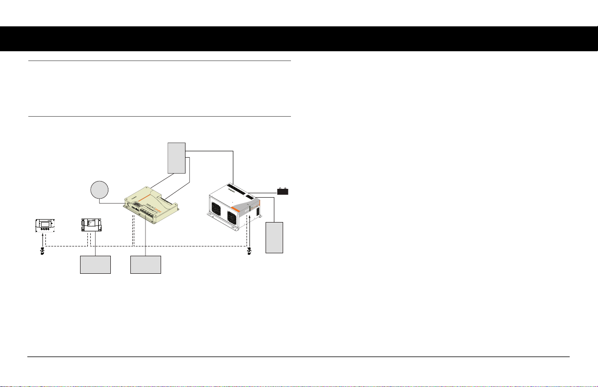
The Xanbus Automatic Generator Start (AGS) is designed
for use in a Xanbus-enabled Freedom SW Power System only.
The Xanbus AGS requires the additional use of a Xanbus System Control
Panel (SCP) for configuration and monitoring. For details see "System
Requirements".
AC Panel
Shore
Power
System Control Panel
Xanbus System Control Panel
network terminator network terminator
Figure 1
Automatic Generator Start
Xanbus Automatic Generator Start
Generator
Xanbus Automatic Generator Start (AGS) Basic Function
Freedom Sequence
AC Loads
Freedom SW Inverter/Charger
FREEDOMSW 3012
BATTERY
C/
ge Fault
r
ter A
ha
r
C
nve
I
On
er
t
r
e
nv
I
Reset Enable
FREEDOM SW 3012
Inverter
Load Panel
Function The Xanbus AGS continuously monitors battery voltage and
starts, or stops, the generator when battery voltage drops below or exceeds
the preset limits. It also starts the generator to assist the system’s inverter/
charger when output power demands are high.
Start and Stop Triggers The Xanbus AGS requires a source of start and
stop triggers for automatic operation. The Xanbus AGS monitors the
Xanbus network and starts or stops the generator based on the preset limits
programmed into it.
975-0082-01-01 1
Page 12

Introduction
System Requirements
Minimum basic system components include the following:
❐ Freedom SW Series Inverter/Charger
❐ AC Generator or DC Generator
❐ Xanbus System Control Panel (SCP)
❐ Xanbus Automatic Generator Start (AGS)
Network Communication Protocol The AGS uses Xanbus, a network
communications protocol developed by Xantrex, to communicate its
settings and activity to other Xanbus-enabled devices. All network
components used in the system must be Xanbus-enabled.
Network Power Supply The Xanbus AGS requires three watts of power
(maximum) to operate. This power supply is provided by the Freedom SW
Series Inverter/Charger through the Xanbus network.
Generator The generator should be a 2-wire or 3-wire generator with
Auto Start capability.
The generator should also supply a Generator Run signal. The Generator
Run signal is connected to the Xanbus AGS and used by the Xanbus AGS
to detect whether the generator is running. Some generator manufacturers
refer to this signal as the Hour Meter Signal or Switched B+.
Connecting the Generator Run signal is optional and only used for
redundancy. The Xanbus AGS requests generator voltage from the Xanbus
in addition to checking the Generator Run signal to detect if the generator is
running.
Generator Compatibility The Xanbus AGS supports most two and
three-wire generator starters. Some manufacturers include, but are not
limited to, Onan (Quiet Diesel, gasoline, and LP), Power Tech, Generac,
Northern Lights, Fisher Panda, Westerbeke, Kohler, Honda, and Yamaha.
Check with the generator manufacturer to ensure the generator in question
includes automatic starting capabilities.
Xanbus System Control Panel (SCP) A Xanbus System Control Panel
(SCP) is required to configure the AGS and monitor generator starting and
stopping activity.
The Xanbus System Control Panel (SCP) also provides real-time clock
information for the AGS Quiet Time and Exercise Time features.
2 Xanbus Automatic Generator Start (AGS) Owner’s Guide
Page 13

Functions
Introduction
Generator Starting Triggers
The AGS can automatically start a generator in response to:
• a low battery voltage,
• large AC loads when inverter is operating,
• a thermostat signal, or
• a pre-programmed exercise period at a specified time of day.
Generator Stopping Triggers
The AGS can automatically stop a generator in response to:
• the introduction of qualified grid power (grid power within acceptable
parameters),
• high battery voltage,
• battery charge stage (float or absorb stage),
• reduction in AC loads when inverter is operating,
• a thermostat signal, or
• a pre-programmed quiet time period.
The AGS can also be used to manually start and stop the generator at any
time.
Programmable Features
Quiet Time The AGS features a quiet time setting, wh ich prevents the
generator starting at night or during other inconvenient periods.
Exercise Period During times of prolonged generator inactivity, the
AGS can be programmed to run (or “exercise”) the generator for a predefined period. This ensures the generator remains operational and that the
starting battery stays charged.
Status Reporting
The AGS reports its operating mode, its settings, generator activity, and the
reason for generator starts to the Xanbus system. This information can be
viewed on the Xanbus System Control Panel (SCP).
Installation Options
The AGS can be installed with an external shutdown input, a manual
generator ON/OFF switch, and an external ON/OFF indicator light.
975-0082-01-01 3
Page 14
Introduction
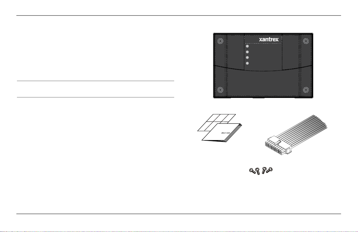
Material List
The AGS ships with the following items:
• one Xanbus Automatic Generator Start (AGS) unit,
• owner’s guide,
• wiring harness (20-pin connector),
• mounting template, and
• mounting screws (4).
NOTE: Keep the carton and packing material in case you need to return
the AGS for servicing.
AGS
unit
Xanbus Automatic Generator Start (AGS)
owner’s guide and
mounting template
Power
TM
Generator On
Network
Fault
FGA: 809-0915
wiring harness
mounting screws
4 Xanbus Automatic Generator Start (AGS) Owner’s Guide
Page 15
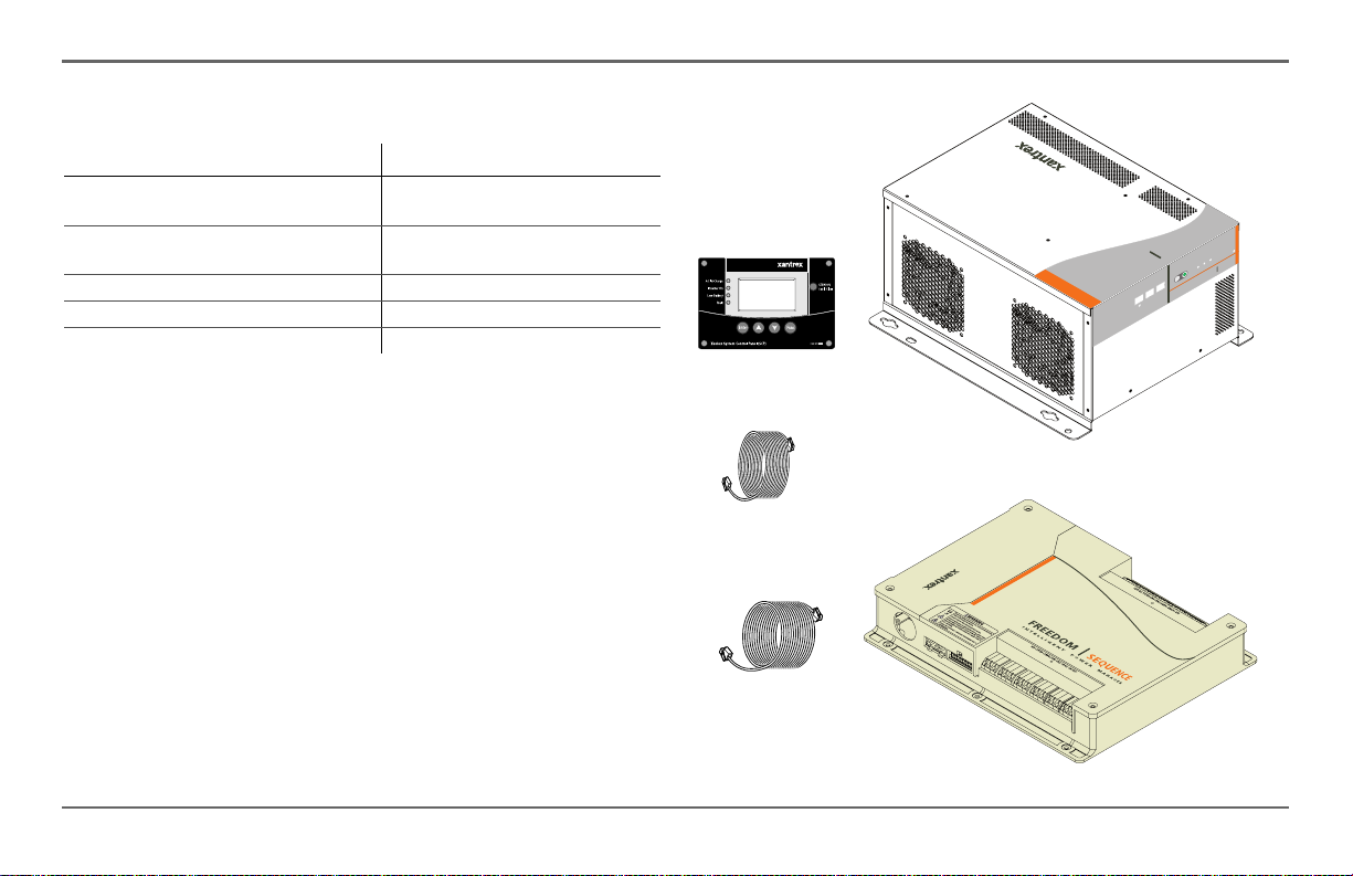
Xanbus-Enabled Products and Accessories
Product/Accessory Product Number
Freedom SW Series Inverter/Charger 815-2012 (2kW power rating),
Freedom Sequence Intelligent Power
Manager
Xanbus System Control Panel (SCP) 809-0921
25-ft network cable for SCP 809-0940
75-ft network cable for SCP 809-0942
The Freedom SW Inverter/Charger is a true sine wave inverter/charger that
can be used for mobile, marine and commercial applications. The Freedom
SW Inverter/Chargers are designed to operate with a wide variety of
generators and are capable of operating in parallel with a generator for short
durations to assist with starting large loads. The Freedom SW is a
convenient combination of an inverter, multistage battery charger, and
transfer switch in one electronic device.
The Xanbus SCP provides configuration and monitoring capability for a
Xanbus system. It monitors activity throughout your power system,
displays the settings and status, as well as, adjusting the settings for each
Xanbus-enabled device.
The Freedom Sequence Intelligent Power Manager is a fully integrated
power management system that provides automatic power and load
management for use in recreational vehicles (RV) while receiving power
from a generator or shore power.
815-3012 (3kW power rating)
809-0913 (four-circuit model),
809-0912 (six-circuit model)
SCP
25-ft cable
75-ft cable
Freedom SW
Inverter/Charger
TM
Introduction
ter
r
e
v
n
I
Reset Enable
FREEDOM SW 3012
Freedom Sequence
power manager
nverter AC/
I
On
FREEDOM SW
Charge Fault
3012
975-0082-01-01 5
Page 16
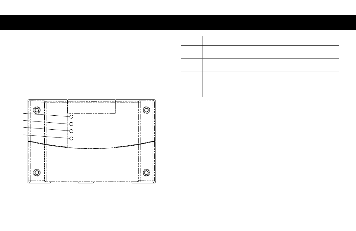
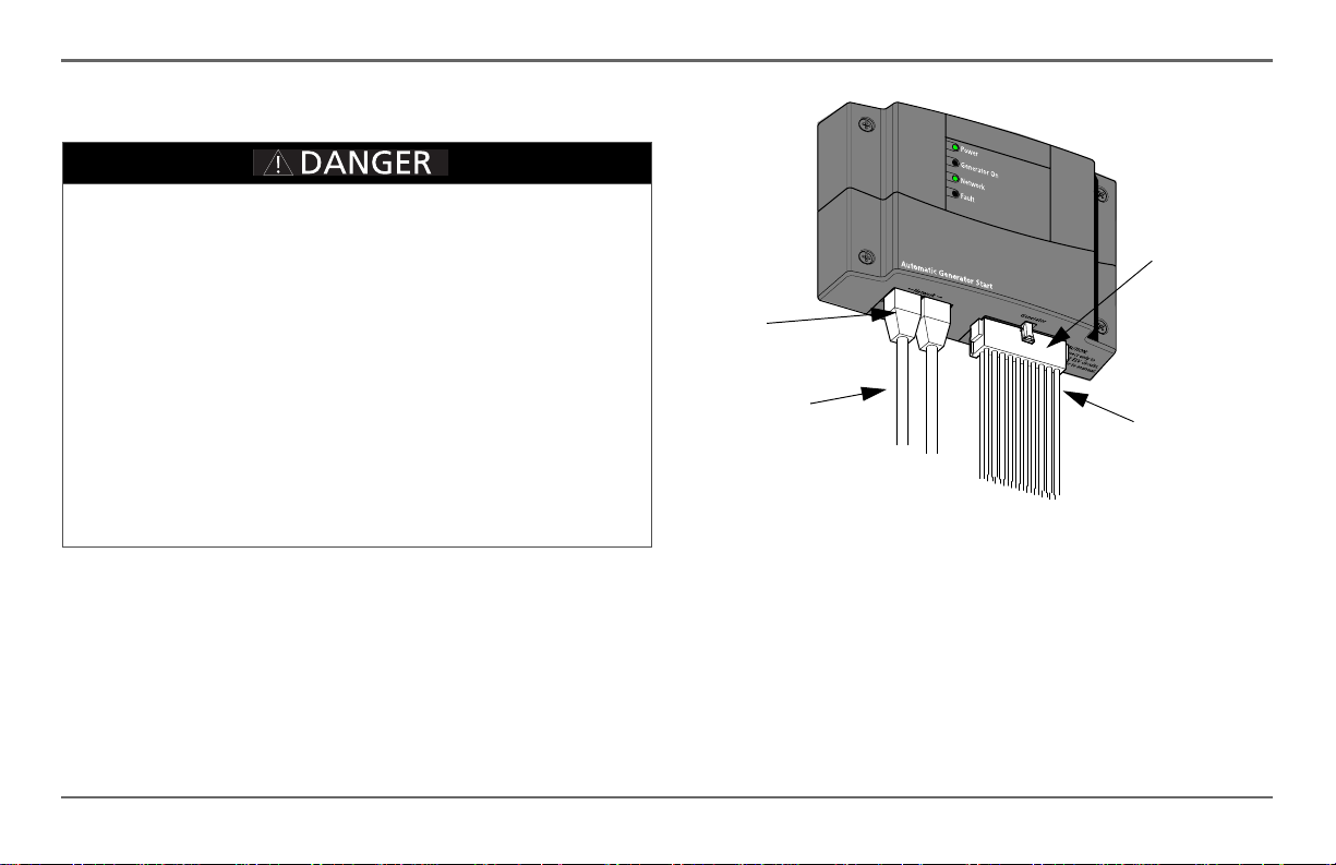
Features
The AGS has important features on the front and back of the unit. Features
on the front of the AGS are the indicator lights for reporting statuses on
power, generator, network, and faults (see Figure 2). The back of the unit
features the inputs where the AGS connects to the Xanbus system and the
20-contact wiring harness connector port (see Figure 3).
Front panel features
1
2
3
4
Xanbus Automatic Generator Start (AGS)
Power
Generator On
Network
Fault
FGA: 809-0915
Item Description
1Power light (green) indicates that the AGS is receiving power from the
Xanbus network.
2 Generator On light (green) indicates that the generator is up and
running.
3Network light (green) indicates that the Xanbus network is
maintaining a good connection with all Xanbus-enabled components.
4Fault light (red) indicates the generator is experiencing a fault and
requires user attention and intervention.
Figure 2
AGS Front Panel
6 Xanbus Automatic Generator Start (AGS) Owner’s Guide
Page 17
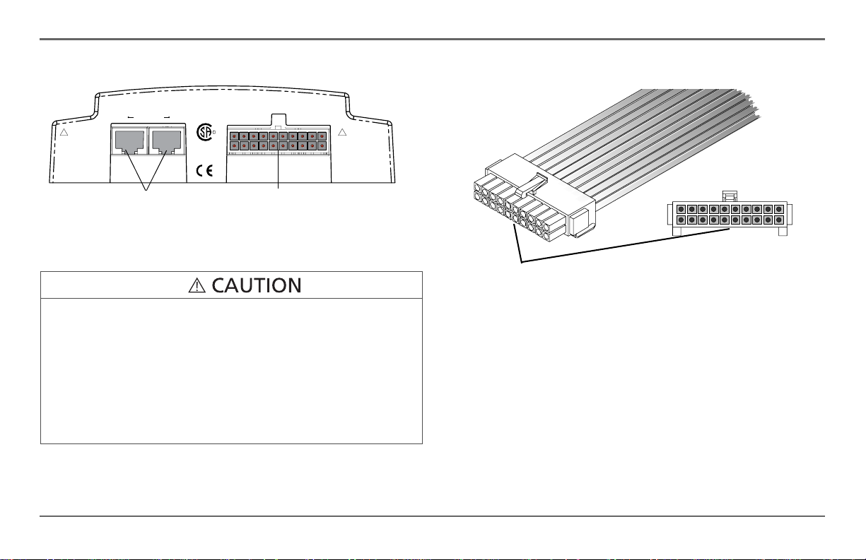
Bottom panel features
Features
Gener at or
20-contact generator
connector port
!
WARNING
Explosion hazar d.
Do n ot ins tall in A
loc ation requiring
ignition pr otected
equipmen t. see
man ual .
!
CAUTION
CONNECT ONLY TO
CLASS 2 ELV CIRCUITS.
SEE MANUAL.
Figure 3
XANBUS
Two 8-pin RJ-45 Xanbus
network ports
AGS Bottom Panel
C
CSA 107.1
UL 458
LR 86581
MARINE
RR
US
EQUIPMENT DAMAGE
Only connect the Xanbus Automatic Generator Start (AGS) to other
Xanbus-enabled devices.
Although the cabling and connectors used in this network system are the
same as those used for Ethernet, this network is not an Ethernet system.
Equipment damage may result from attempting to connect these two
different systems.
Failure to follow these instructions can result in minor or moderate
injury.
Network Ports Each network port can accept an eight-pin RJ45 plug
attached to a Category 5 (CAT 5) Xanbus network cable. Depending on the
installation, both ports may be required.
20-contact wiring harness
connector
Figure 4
Wiring Harness Connector
Wiring Harness Connector The 20-contact connector supports a wiring
harness (supplied) that connects the AGS to a generator and thermostats.
The wiring harness also provides lines for connecting external generator
shutdown sensors or switches and external generator ON/OFF controls.
975-0082-01-01 7
Page 18

Xanbus Automatic Generator Start Installation
Before installing the A GS, consider how and where the unit will be mounted.
Pre-plan the connection routes between the AGS, the generator, thermostats,
and the Xanbus System Control Panel (SCP).
Materials and Tools Required
The following materials and tools are required to complete the installation:
❐ Mounting template (supplied)
❐ Wiring harness (manufacturer part number 809-0917, supplied)
❐ Four mounting screws (supplied)
❐ #16 or #18 AWG wire (see “Wire Size and Length” on page 12)
❐ Xanbus network cables or equivalent (CAT 5 or CAT 5e cable with RJ-
45 connectors wired to T568A standard.
❐ Two network terminators
(supplied with the Freedom SW Inverter/Charger)
❐ Phillips head screwdriver
❐ Wire cutters and wire strippers
Choosing a Location
The AGS should be installed in a location that meets the following
requirements:
Dry
Cool
Safe
Close to
generator
The unit is intended for use in a dry location. The AGS
complies with UL458 Marine Supplement drip-test
requirements, but the location should be as dry as
possible.
The AGS operation is guaranteed between
-4 and 122 °F (-20 and 50 °C).
The AGS is not ignition protected. Do not install it in
areas requiring ignition-protected equipment, such as
compartments housing gasoline engines.
Avoid excessive wire lengths and use the
recommended wire lengths and sizes (see “Wire Size
and Length” on page 12). It is more important for the
AGS
to be close to the generator than close to the
inverter, although for safety reasons, the AGS should
not be installed in the same compartment as a gasolinepowered generator.
8 Xanbus Automatic Generator Start (AGS) Owner’s Guide
Page 19
Routing Connections
EXPLOSION HAZARD
This equipment is not ignition protected. To prevent fire or explosion, do
not install the AGS in locations that require ignition-protected equipment.
This includes any space containing gasoline-powered machinery, fuel
tanks, as well as joints, fittings, or other connections between
components of a fuel system.
Follow all relevant instructions exactly before installing or using your
AGS.
SHOCK AND ENERGY HAZARDS
Before making any connections to the generator, ensure that the
generator’s starter is disabled and the generator’s start battery is
disconnected.
Failure to follow these instructions will result in death or serious
injury.
Connection Types Because the AGS will be part of a Xanbus system, it
is necessary to consider how to route two types of connections:
• connections to the generator, thermostats, and other external devices
and switches, using the included 20-contact connector and wiring
harness.
• connections to other Xanbus-enabled devices, using network cables.
Network ports
Network cables
to other Xanbusenabled devices
Figure 5
Xanbus Automatic Generator Start Installation
AGS External Connections
20-contact
connector
Wiring harness
(connection to
generator,
thermostats, and
external switches)
975-0082-01-01 9
Page 20

Xanbus Automatic Generator Start Installation
Installation Overview
Installing the AGS involves the following steps:
1. Mounting the unit.
2. Connecting the wiring harness to:
• the generator (page 14)
• thermostats (optional) (page 29)
• external shutdown switch (optional) (page 30)
• external ON/OFF switch and LED (optional) (page 30)
ELECTRICAL SHOCK HAZARD
Before installing the AGS as part of a pre-existing Xanbus system, put
the system in Standby in order to disable the electrical operation of
networked devices. See “Putting the AGS in Standby Mode” on page 67.
Failure to follow these instructions can result in death or serious
injury.
3. Connecting the wiring harness to the 20-contact connector on the
AGS.
4. Connecting the AGS to the Xanbus System Control Panel (SCP) and
other network-enabled devices (page 33).
IMPORTANT:
the type of generator, and the overall complexity of the Xanbus system,
these instructions can offer only general guidelines for the many
installation options available.
Because each installation varies according to the location,
Mounting the Unit
The AGS is to be mounted vertically on a wall with the connectors facing
downwards.
To mount the AGS:
1. Hold the unit flush and square against the wall, panel, or horizontal
surface.
• If the mounting surface requires pre-drill holes for the screws, use
the supplied mounting template to mark, then drill, four holes.
2. With a Phillips screwdriver and the supplied mounting screws, secure
each corner of the AGS to the mounting surface.
10 Xanbus Automatic Generator Start (AGS) Owner’s Guide
Page 21
Wiring to the 20-contact Connector
ELECTRICAL SHOCK HAZARD
All installation wiring should be performed by a qualified installer or
electrician.
The 20-contact connector is intended for connection to Class 2 ELV
(Extra Low Voltage) circuits only. Do not exceed the circu it limitations
specified in the following section.
Failure to follow these instructions can result in death or serious
injury.
ELV Circuits ELV (Extra-Low Voltage) circuits have an open-circuit
voltage of not more than 30 V
not a shock hazard.
Class 2 Circuits As per the US National Electrical Code (NEC) and the
Canadian Electrical Code (CEC), available power in Class 2 circuits is
limited to 100 VA, usually by current limiting by means of overcurrent
protection or series resistance. The current is limited to 5 A for circuits with
open-circuit voltage of 20 V, and to I=100/V
voltage between 20 V and 30 V.
or 42.2 VDC or peak, and are therefore
rms
for circuits with open circuit
oc
Xanbus Automatic Generator Start Installation
Circuit Limitations The relay contacts in the AGS are rated at 5 A
maximum and all circuits on the 20-contact connector are rated at 30 V
maximum.
Ensure that all circuits connected to the 20-contact connec tor comply with
the following limits:
Circuit Parameter Circuit Maximum
Open circuit voltage (Voc) 30 V maximum
Overcurrent protection
(fuse size for open circuit voltage up to 20 V)
Overcurrent protection
(fuse size for open circuit voltage from 20 V to
30 V)
Wiring Harness Connections to the generator, thermostats, and external
ON/OFF switches are made using a wiring harness that plugs into the 20contact connector (see Figure 5).
The wires on the wiring harness can be extended to meet installation
requirements. When extending the wire harness, ensure that the extension
wires are the same color as the wires on the harness.
5 A maximum
5 A to 3.33 A
(100/V
maximum)
amps
oc
975-0082-01-01 11
Page 22
Xanbus Automatic Generator Start Installation
To install the AGS using the wiring harness:
1. Connect each wire on the harness to its intended wire or contact on the
generator, thermostats, or external sw itches. Tape, or otherwise secure,
the unused wires to ensure they do not make unintended connections.
2. Plug the harness into the connector on the bottom panel of the AGS.
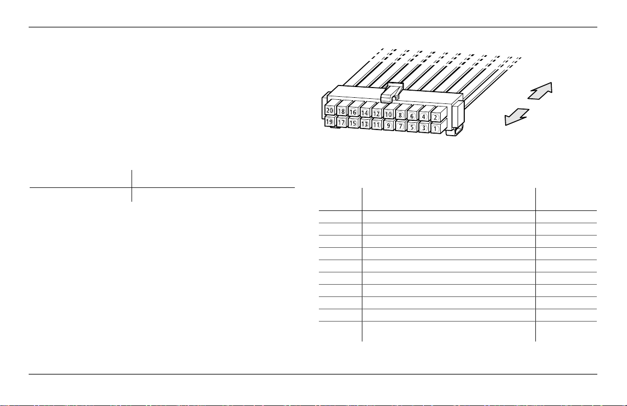
Wire Identification Each wire on the harness is identified by a number
and a color. The wire numbers are shown in Figure 6 and their colors and
functions are described in the next table.
Wire Size and Length Required wire sizes for the external connections
to the wiring harness are:
0–30 ft. (9 m) Over 30 ft. (9 m)
18 AWG 16 AWG
When planning the routing for external connections, ensure that wire
lengths are sufficient to plug the wiring harness into the AGS once all the
external connections are complete.
To generator,
thermostats, and
external switches
To 20-contact
connector on AGS
Figure 6
Wire
Number Function
1 Thermostat 1 input Yellow
2 Thermostat 1 return Gray
3 Thermostat 2 input Orange
4 Thermostat 2 return Gray
5 External shutdown input White/Black
6 External shutdown return Gray
7 External manual on input White/Green
8 External manual off input White/Red
9 External ON/OFF LED Indicator output White/Blue
10 Constant 12/24 V B+ (battery positive) for External ON/
AGS Wiring Harness
OFF/LED Indicator
Wiring Harness
Wire Color
Red
12 Xanbus Automatic Generator Start (AGS) Owner’s Guide
Page 23

Wire
Number Function
11 External ON/OFF/LED Indicator return (connected
12
13
14
15
16
17
18
19
20
internally to wire number 13)
Generator run signal (switched B+) sense input
Generator run signal (switched B+) sense return
Relay 1 (Generator run/stop) Normally open contact
Relay 1 (Generator run/stop) Normally closed contact
Relay 1 (Generator run/stop ) C om m o n co nt act
Relay 2 (Generator start) Normally open contact
Relay 2 (Generator start) Common contact
Relay 3 (Preheat/cool-down) Normally open contact
Relay 3 (Preheat/cool-down) Common contact
Wiring Harness
Wire Color
Black
Violet
Black
Blue
White/Violet
Gray
White
Gray
Brown
Gray
Xanbus Automatic Generator Start Installation
975-0082-01-01 13
Page 24
Xanbus Automatic Generator Start Installation
Connecting the Generator
EQUIPMENT DAMAGE
Before connecting the AGS to your generator, read the Generator Type
descriptions in this section and consult your generator manufacturer to
ensure that Gen Type settings and connections are compatible with your
generator. Damage to the generator can result from selecting an inc o rre ct
Gen Type and following the connection diagram for an incorrect Gen
Type when connecting the AGS to the generator. Xantrex assumes no
responsibility or liability for loss or damage that might arise out of the use
of this information.
Failure to follow these instructions can damage the unit and/or
damage other equipment.
To connect the AGS to a generator , identify the start wiring configuration of
the generator to be used. Generators must be auto-start capable, and
generators equipped with remote operation connections are ideal.
If the generator is equipped for remote operation, examine the wiring of the
remote cable and connector (or read the generator’s documentation, if
available) and identify the following wires:
• Ground
•Start
•Stop
• Generator run signal, also known as the Hour Meter or Switched B+
(battery positive)
Wiring Requirements Either #16 or #18 AWG wire is required to
connect to the wiring harness. How many of these wires you connect and in
which combination depends on your generator type.
Generator Types The AGS has 14 preset generator configurations, or
“Gen Types” (see “Gen T ype” on page 42). After installing the hardware, it
will be necessary to select one of these Gen Types from the AGS
Configuration Menu on the Xanbus System Control Panel (SCP).
IMPORTANT:
Type". See “Putting the AGS in Standby Mode” on page 67.
The following section describes the preset generator configurations and
provides diagrams for connecting the wiring harness to the generator’s start
wiring.
IMPORTANT:
following section, refer to Appendix 1, “Appendix A: Generator Auto
Start Requirements and Types”. For more information about AGS
internal relay activity and timing, see Appendix 1, “Appendix B: Relay
Timing”.
IMPORTANT:
B+ Gen Run signal is not connected, it may be necessary to adjust the
Gen Run Signal hold time parameter on the AGS. See “Gen Run Hold
Time” on page 57.
Put the system in Standby BEFORE changing the "Gen
For an explanation of the terminology used in the
Connecting the B+ Gen Run signal is optional. It the
14 Xanbus Automatic Generator Start (AGS) Owner’s Guide
Page 25
Type 1
Xanbus Automatic Generator Start Installation
Type 1 is a three-wire GlowStop configuration recommended for “threewire” generators with glow plugs that need to be operated before a start is
attempted.
AGS Har ness Wires Generator W ires
12
13
14
Relay1
16
17
Relay2
18
For additional information, see “Circuit Limitations” on page 11.
Figure 7
Type 1 Connection Diagram
GENERATOR RUN SIGNAL
GENERATOR RUN SIGNAL RETURN
5A fuse
PREHEAT/STOP
5A fuse
START
Relay Function Preset Configuration Setting
Relay 1 mode GlowStop
Relay 3 mode No function
Gen Run signal hold time 0.5 s
Preheat time 20 s
Preheat to crank delay 1 s
Crank time 15 s
Relay Function Preset Configuration Setting
Crank retry time 30 s
Gen Cool Down 30 s
Gen Spin Down 3 s
Shutdown bypass time 0 s
Start tries 3
975-0082-01-01 15
Page 26
Xanbus Automatic Generator Start Installation
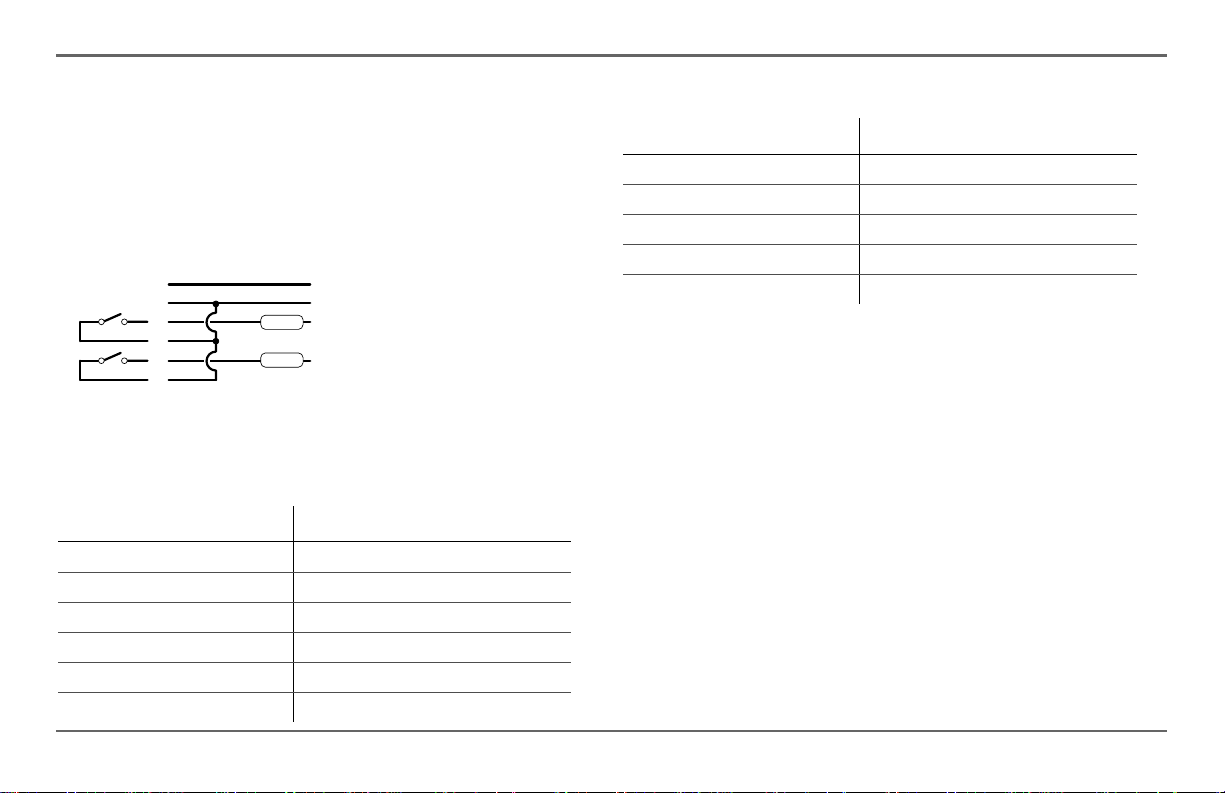
Type 2
Type 2 is a three-wire GlowStop configuration recommended for “threewire” generators that don’t require a dedicated preheat signal. In this
configuration, the start signal is applied for longer because the generator
does its own preheat and cranking while the start signal is applied.
AGSHarnessWires Generator Wires
12
13
14
Relay1
16
17
Relay2
18
For additional information, see “Circuit Limitations” on page 11.
Figure 8
Type 2 Connection Diagram
GENERATOR RUN SIGNAL
GENE RATOR RUN SIGNAL RETURN
5A fuse
STOP/PREHEAT
5A fuse
START
Relay Function Preset Configuration Setting
Relay 1 mode GlowStop
Relay 3 mode No function
Gen Run signal hold time 0.5 s
Preheat time 0 s
Preheat to crank delay 0 s
Relay Function Preset Configuration Setting
Crank time 30 s
Crank retry time 40 s
Gen Cool Down 30 s
Gen Spin Down 3 s
Shutdown bypass time 0 s
Start tries 3
16 Xanbus Automatic Generator Start (AGS) Owner’s Guide
Page 27
Type 3
Xanbus Automatic Generator Start Installation
Type 3 is a three-wire GlowStop with shutdown bypass configuration. The
configuration shown in Figure 9 uses a shutdown bypass output to
temporarily disable the generator’s low oil pressure shutdown functionality
during cranking. Generators with this functionality often have a manual
means of disabling it during cranking.
AGS Harness W ires Generator Wires
12
13
Relay 1
Relay 2
For additional information, see “Circuit Limitations” on page 11.
Figure 9
14
16
17
18
Type 3 Connection Diagram
5A fuse
5A fuse
GENERATOR RUN SIGNAL
GENERATOR RUN SIGNAL RETURN
PREHEAT
STOP
BYPASS SHUTDOWN
START
Relay Function Preset Configuration Setting
Relay 1 mode GlowStop/Shutdown bypass
Relay 3 mode Preheat/Shutdown bypass
Gen Run signal hold time 0.5 s
Preheat time 20 s
Relay Function Preset Configuration Setting
Preheat to crank delay 0 s
Crank time 15 s
Crank retry time 30 s
Gen Cool Down 30 s
Gen Spin Down 3 s
Shutdown bypass time 10 s
Start tries 3
975-0082-01-01 17
Page 28
Xanbus Automatic Generator Start Installation
Type 4
Type 4 is a three-wire StartStop configuration that uses relay 3 to provide a
60-second preheat signal.
AGS Harness W ires
12
13
Relay 1
Relay 2
Relay 3
For additional information, see “Circuit Limitations” on page 11.
Figure 10
14
16
17
18
19
20
Type 4 Connection Diagram
5A fuse
5A fuse
5A fuse
Generator Wires
GENERATOR RUN SIGNAL
GENERATOR RUN SIGNA L RETURN
STOP/PREHEAT
START
FUEL PRIME (PREHEAT)
12V GENERATOR BATTERY+
Relay Function Preset Configuration Setting
Relay 1 mode StartStop
Relay 3 mode Preheat
Gen Run signal hold time 10 s
Preheat time 60 s
Relay Function Preset Configuration Setting
Preheat to crank delay 5 s
Crank time 15 s
Crank retry time 15 s
Gen Cool Down 30 s
Gen Spin Down 3 s
Shutdown bypass time 0 s
Start tries 3
18 Xanbus Automatic Generator Start (AGS) Owner’s Guide
Page 29

Type 5
Xanbus Automatic Generator Start Installation
Type 5 is a three-wire StartStop configuration that uses relay 3 to provide a
15-second preheat signal.
AGS Harness W ires Generator W ires
12
13
Relay 1
Relay 2
Relay 3
For additional information, see “Circuit Limitations” on page 11.
Figure 11
14
16
17
18
19
20
Type 5 Connection Diagram
5A fuse
5A fuse
5A fuse
GENERATOR RUN SIGNAL
GENERATOR RUN SIGNAL RETURN
STOP/PREHEAT
START
FUEL PRIME (PREHEAT)
12V GENERATOR BATTERY+
Relay Function Preset Configuration Setting
Relay 1 mode StartStop
Relay 3 mode Preheat
Gen Run signal hold time 2 s
Preheat time 15 s
Preheat to crank delay 2 s
Relay Function Preset Configuration Setting
Crank time 15 s
Crank retry time 15 s
Gen Cool Down 30 s
Gen Spin Down 3 s
Shutdown bypass time 0 s
Start tries 3
975-0082-01-01 19
Page 30
Xanbus Automatic Generator Start Installation
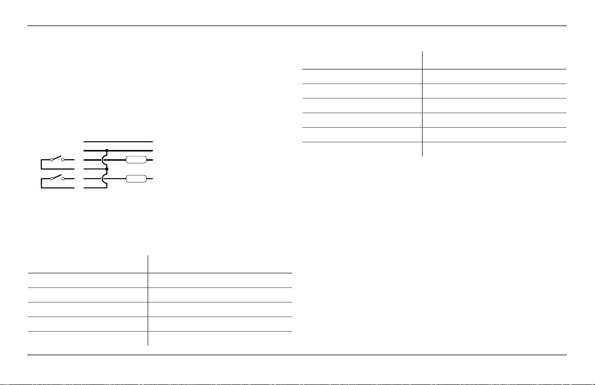
Type 6
Type 6 is a three-wire GlowStop configuration that has a normally closed
Run/Stop contact.
AGS Harness Wires Generator W ires
12
13
14
Relay1
Relay2
For additional information, see “Circuit Limitations” on page 11.
Figure 12
15
16
17
18
Type 6 Connection Diagram
5A fuse
5A fuse
5A fuse
GENERATOR RUN SIGNAL
GENERATOR RUN SIGNAL RETURN
PREHEAT
STOP
START
Relay Function Preset Configuration Setting
Relay 1 mode GlowStop
Relay 3 mode No function
Gen Run signal hold time 0.5 s
Preheat time 10 s
Preheat to crank delay 1 s
Crank time 15 s
Relay Function Preset Configuration Setting
Crank retry time 30 s
Gen Cool Down 30 s
Gen Spin Down 3 s
Shutdown bypass time 0 s
Start tries 3
20 Xanbus Automatic Generator Start (AGS) Owner’s Guide
Page 31

Type 7
Xanbus Automatic Generator Start Installation
Type 7 will work with both two-wire and three-wire run mode configurations
that require a preheat signal before cranking. This Gen Type setting is suitable
for generators with an automatic engine cranking control system (two-wire)
and generators that require that the AGS control their starter separately (threewire).
AGS Harness W ires Generator W ires
12
13
Relay 1
For additional information, see “Circuit Limitations” on page 11.
Figure 13
AGS Harness W ires Generator Wires
Relay1
Relay2
For additional information, see “Circuit Limitations” on page 11.
14
16
Type 7 Connection Diagram (two-wire)
12
13
14
16
17
18
5A fuse
5A fuse
5A fuse
GENERATOR RUN SIGNAL
GENERATOR RUN SIGNAL RETURN
RUN
GENERATOR RUN SIGNAL
GENERATOR RUN SIGNAL RETURN
RUN
START
Relay Function Preset Configuration Setting
Relay 1 mode Run
Relay 3 mode No function
Gen Run signal hold time 0.5 s
Preheat time 20 s
Preheat to crank delay 1 s
Crank time 15 s
Crank retry time 30 s
Gen Cool Down 30 s
Gen Spin Down 3 s
Shutdown bypass time 0 s
Start tries 3
Figure 14
Type 7 Connection Diagram (three-wire)
975-0082-01-01 21
Page 32

Xanbus Automatic Generator Start Installation
Type 8
Type 8 will work with both two-wire and three-wire run mode
configurations. Type 8 is identical to Type 7 except that it provides no
preheat signal before cranking.
AGS Har ness Wires Generator W ires
12
13
14
Relay 1
16
For additional information, see “Circuit Limitations” on page 11.
Figure 15
AGS Harness W ires Generator W ires
For additional information, see “Circuit Limitations” on page 11.
Type 8 Connection Diagram (two-wire)
12
13
14
Relay1
16
17
Relay2
18
5A fuse
5A fuse
5A fuse
GENERATOR RUN SIGNAL
GENERATOR RUN SIGNAL RETURN
RUN
GENERATOR RUN SIGNAL
GENERATOR RUN SIGNA L RETURN
RUN
START
Relay Function Preset Configuration Setting
Relay 1 mode Run
Relay 3 mode No function
Gen Run signal hold time 0.5 s
Preheat time 0 s
Preheat to crank delay 0 s
Crank time 15 s
Crank retry time 30 s
Gen Cool Down 30 s
Gen Spin Down 3 s
Shutdown bypass time 0 s
Start tries 3
Figure 16
Type 8 Connection Diagram (three-wire)
22 Xanbus Automatic Generator Start (AGS) Owner’s Guide
Page 33

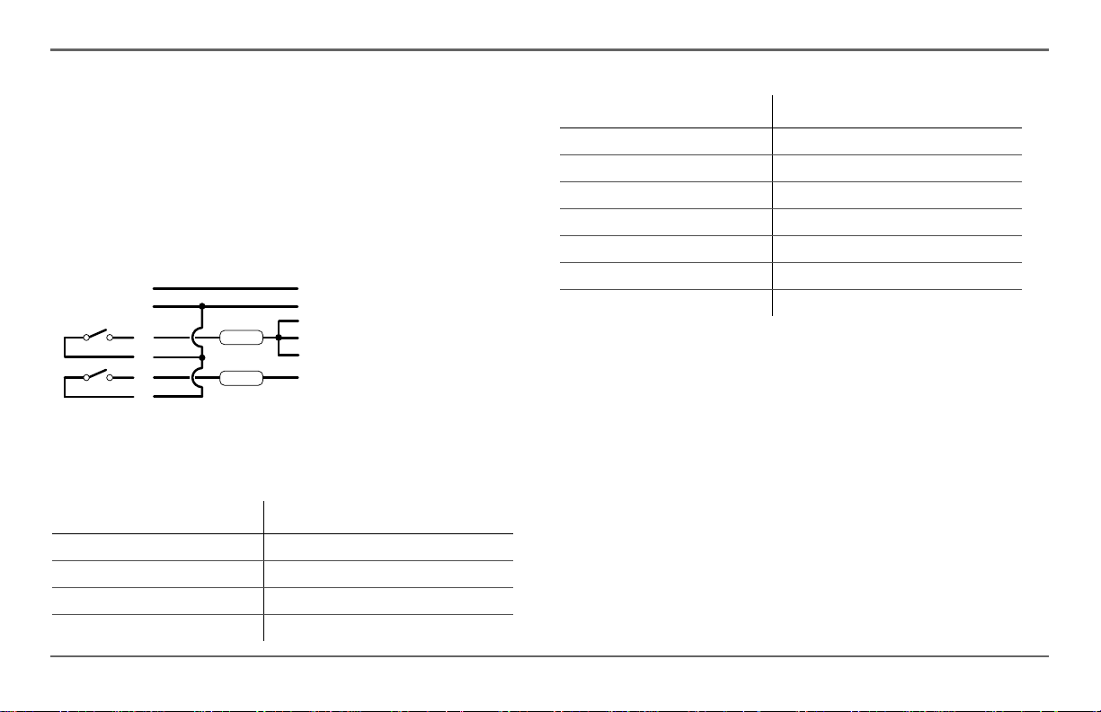
Type 9
Xanbus Automatic Generator Start Installation
Type 9 is a StartStop mode configuration with shutdown bypass
functionality on relay 3.
AGS Harness Wires Generator W ires
12
13
Relay1
Relay2
Relay3
For additional information, see “Circuit Limitations” on page 11.
Figure 17
14
16
17
18
19
20
Type 9 Connection Diagram
GENERATOR RUN SIGNAL
GENERATOR RUN SIGNAL RETURN
5A fuse
STOP
5A fuse
START
5A fuse
FUEL PRIME (PREHEAT)
12V GENERATOR BATTERY+
Relay Function Preset Configuration Setting
Relay 1 mode StartStop
Relay 3 mode Shutdown Bypass
Gen Run signal hold time 0.5 s
Preheat time 0 s
Preheat to crank delay 0 s
Relay Function Preset Configuration Setting
Crank time 15 s
Crank retry time 30 s
Gen Cool Down 30 s
Gen Spin Down 3 s
Shutdown bypass time 5 s
Start tries 3
975-0082-01-01 23
Page 34

Xanbus Automatic Generator Start Installation
Type 10
Type 10 is a StartStop mode configuration with no preheat signal or
shutdown bypass functionality.
AGS Harness Wires Generator W ires
12
13
Relay 1
Relay 2
For additional information, see “Circuit Limitations” on page 11.
Figure 18
14
16
17
18
Type 10 Connection Diagram
GENERATOR RUN SIGNAL
GENERATOR RUN SIGNAL RETURN
5A fuse
STOP
5A fuse
START
Relay Function Preset Configuration Setting
Relay 1 mode StartStop
Relay 3 mode No function
Gen Run signal hold time 0.5 s
Preheat time 0 s
Preheat to crank delay 0 s
Crank time 15 s
Crank retry time 30 s
Relay Function Preset Configuration Setting
Gen Cool Down 30 s
Gen Spin Down 3 s
Shutdown bypass time 0 s
Start tries 3
24 Xanbus Automatic Generator Start (AGS) Owner’s Guide
Page 35

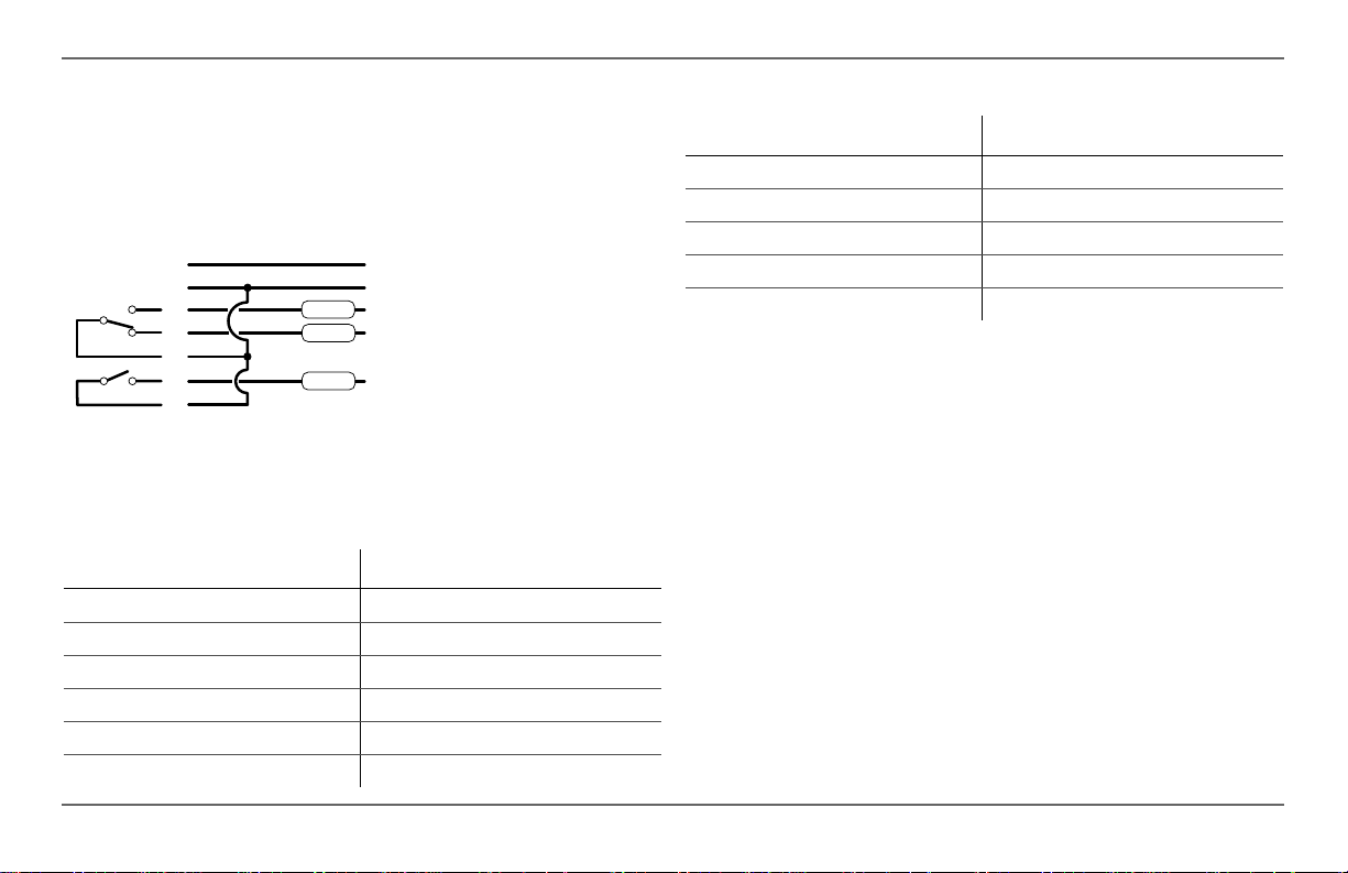
Type 11
Xanbus Automatic Generator Start Installation
Type 11 is a two-wire run mode configuration. It requires only two wires
and one relay to control the generator. Relay 1 closes momentarily once to
start the generator, and closes momentarily again to stop the generator.
AGS Harness Wires Generator Wires
12
13
Relay 1
For additional information, see “Circuit Limitations” on page 11.
Figure 19
14
16
Type 11 Connection Diagram
5A fuse
GENERATOR RUN SIGNAL
GENERATOR RUN SIGNAL RETURN
RUN
Relay Function Preset Configuration Setting
Relay 1 mode MomentaryRun
Relay 3 mode No function
Gen Run signal hold time 0.5 s
Preheat time 0 s
Preheat to crank delay 0 s
Crank time 10 s
Crank retry time 15 s
Gen Cool Down 30 s
Relay Function Preset Configuration Setting
Gen Spin Down 3 s
Shutdown bypass time 0 s
Start tries 3
975-0082-01-01 25
Page 36

Xanbus Automatic Generator Start Installation
Type 12
Type 12 is a three-wire GlowStop configuration recommended for “threewire” generators that don’t require a dedicated preheat signal. In this
configuration, the start signal is applied for longer because the generator
does its own preheat and cranking while the start signal is applied.
AGS Harness Wires Generator W ires
12
13
Relay 1
Relay 2
For additional information, s ee “Circuit Limitations” on page 11.
Figure 20
14
16
17
18
Type 12 Connection Diagram
GENERATOR RUN SIGNAL
GENERATOR RUN SIGNAL RETURN
5A fuse
STOP
5A fuse
START
Relay Function Preset Configuration Setting
Relay 1 mode GlowStop
Relay 3 mode No function
Gen Run signal hold time 4 s
Preheat time 0 s
Preheat to crank delay 0 s
Crank time 30 s
Relay Function Preset Configuration Setting
Crank retry time 40 s
Gen Cool Down 30 s
Gen Spin Down 3 s
Shutdown bypass time 0 s
Start tries 3
26 Xanbus Automatic Generator Start (AGS) Owner’s Guide
Page 37

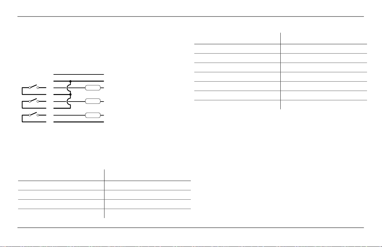
Type 13
Xanbus Automatic Generator Start Installation
Type 13 is a three-wire PulseStop configuration that uses relay 3 to provide
the preheat signal. With this genera tor type, there will be a delay between
the generator turning off and the AGS recognizing that the generator is off.
AGS Harness W ires Generator Wires
12
13
Relay 1
Relay 2
Relay 3
For additional information, see “Circuit Limitations” on page 11.
Figure 21
14
16
17
18
19
20
Type 13 Connection Diagram
5A fuse
5A fuse
5A fuse
GENERATOR RUN SIGNAL
GENERATOR RUN SIGNAL RETURN
STOP/PREHEAT
START
FUEL PRIME (PREHEAT)
12V GENERATOR BATTERY+
Relay Function Preset Configuration Setting
Relay 1 mode PulseStop
Relay 3 mode Preheat
Gen Run signal hold time 5 s
Relay Function Preset Configuration Setting
Preheat time 15 s
Preheat to crank delay 2 s
Crank time 15 s
Crank retry time 15 s
Gen Cool Down 30 s
Gen Spin Down 3 s
Shutdown bypass time 0 s
Start tries 3
975-0082-01-01 27
Page 38

Xanbus Automatic Generator Start Installation
Type 14
Type 14 works with two-wire generators that use an integrated engine
control module to perform the necessary relay cycles to start and stop the
generator. This is similar to Type 8 but without the B+ signal requirement.
The AGS closes relay 1 to start the generator and illuminates the Generator
On light to indicate the relay is closed. To stop the generator, relay 1 is
opened and the Generator On light turned off.
AGS Harness Wires Generator Wires
Relay 1
14
16
5A fuse
RUN
RELAY1 R ETURN
IMPORTANT:
Since Type 14 does not monitor the generator run status,
illumination of the Generator On light on the AGS does not necessarily
indicate the generator is actually running. If this generator type is used,
For additional information, see “Circuit Limitations” on page 11.
Figure 22
Type 14 Connection Diagram (two-wire)
ensure the generator’s integrated controller has the ability to monitor,
control and report generator status and faults. With Type 14, no faults are
raised if the generator fails to start or stop or is externally started or
stopped.
Once the generator is stopped, there is a 10-minute delay before the
generator can be re-started using the AGS. This is to allow the generator’s
integrated engine controller to completely and safely shut down the
generator. This delay can be adjusted by changing the Gen Spin down
setting.
Relay Function Preset Configuration Setting
Relay 1 mode RunStop
Relay 3 mode Not used
Gen Run signal hold time 0 s
Preheat time 0 s
Preheat to crank delay 0 s
Crank time 0 s
Crank retry time 0 s
Gen Cool Down 30 s
Gen Spin Down 600 s
Shutdown bypass time 0 s
Start tries 1
28 Xanbus Automatic Generator Start (AGS) Owner’s Guide
Page 39

Connecting the Thermostats (optional)
Wires 1, 2, 3, and 4 on the wiring harness can be connected to two
thermostats. Wires 1 (yellow) and 2 (gray) are intended for thermostat 1 and
wires 3 (orange) and 4 (gray) are intended for thermostat 2.
Xanbus Automatic Generator Start Installation
Table 1
Wire
Number Function
1 Thermostat 1 input (12/24 V) Yellow
2 Thermostat 1 return (ground) Gray
3 Thermostat 2 input (12/24 V) Orange
4 Thermostat 2 return (ground) Gray
These wires connect to 12-volt/24-volt output signals from the thermostats.
The AGS will start the generator in response to these signals. Thermostats
can not be programmed using the AGS.
For specific information about thermostat wiring and where AGS
connections should be made, please consult your thermostat documentation
or contact the thermostat manufacturer.
Wiring for Connecting Thermostats
Wiring Harness
Wire Color
975-0082-01-01 29
Page 40

Xanbus Automatic Generator Start Installation
Connecting an External Shutdown (optional)
The external shutdown input is a 12-volt/24-volt input used to assure that
the AGS keeps the generator off under conditions that may be potentially
hazardous. Wire 5 (white/black) and 6 (gray) on the wiring harness are
intended for an external switch or sensor (such as a moisture detector, or
carbon monoxide detector) that produces an active high 12-volt or 24-volt
output.
Table 2
Wire
Number Function
5 External shutdown input (12/24 V) White/Black
6 External shutdown return (ground) Gray
Wiring for Connecting an External Shutdown
Wiring Harness
Wire Color
In order for the Xanbus Automatic Generator Start (AGS) to be able to
detect these switches, connect the fused positive of the generator battery to
wire 10 on the harness (the constant 12-volt/24-volt wire). See Figure 23 on
page 32. Ensure all circuits added to the system comply with “Circuit
Limitations” on page 11.
If the generator battery does not have the required voltage, any 12-volt or
24-volt power source meeting the limits on page 11, will suit this purpose.
If an alternate power source is used, its positive terminal must be connected
to wire 10. Its negative must be connected to wire 11.
NOTE: Internally, wire 11 is connected to wire 13, so in this
configuration, the alternative power source negative may already be
connected to the negative terminal on the generator battery.
Connecting an External Manual ON/OFF
Switch (optional)
The external manual ON/OFF inputs (wires 7 and 8 on the wiring harness)
are intended for wiring to one or more remote ON/OFF switches for sta rting
and stopping the generator manually. Wire 7 (Start) and wire 8 (Stop)
should each run to their own momentary-contact switch or push-button. The
other contact on both switches (common) should be connected to wire 11 on
the harness.
NOTE: Internally, wire 11 is connected to wire 13 so it may already be
connected to the negative terminal on the generator battery.
FIRE AND ELECTRICAL SHOCK HAZARD
When making connections to a 12-volt or 24-volt power source that
exceeds the class 2 power limitation of 100 VA (e.g., a battery) always
use over-current protection as defined in Table 2. This also applies to
thermostat and external manual ON/OFF connections. Locate the
protection device at the power source in the positive wire.
Do not connect the AGS to a 48-volt battery bank. The AGS is limited to
a 30V open-circuit maximum by its regulatory approval and cannot be
connected to a 48-volt power source.
Failure to follow these instructions can result in death or serious
injury.
30 Xanbus Automatic Generator Start (AGS) Owner’s Guide
Page 41

Xanbus Automatic Generator Start Installation
The External Manual On and External Manual Of f state s are not af fected by
maximum generator run time (see “Max Run Time” on page 55).
EQUIPMENT DAMAGE
Ta pping 12-volts or 24-volts from a 48-volt battery bank will unevenly
wear out the batteries and shortens the battery bank life.
Failure to follow these instructions can damage the unit and/or
damage other equipment.
Table 3
Wiring for Connecting an External Manual ON/OFF
Switch
Wire
Number Function
7 External manual on input White/Green
8 External manual off input White/Red
9 External On/Off LED Indicator
output
10 Constant 12/24 V B+ for External
On/Off/LED Indicator
11 External On/Off/LED Indicator
return
Multiple generator control panels or simple contact closures can be wired to
the external manual ON/OFF inputs. The AGS detects if any of the contacts
close and will change its operating mode to External Manual On or External
Manual Off (for more information, see “GenMode” on page 60). The AGS
turns the generator on or off according to these inputs and the resulting
operating mode change.
Wiring Harness
Wire Color
White/Blue
Red
Black
Connecting an External ON/OFF LED
Wires 9 (White/Blue) and 1 1 (Black) on the wiring harness can be
connected to an LED or other light to accompany a remote external ON/
OFF switch. This light turns on when the generator run signal is active to
visually indicate that the generator is running.
IMPORTANT:
active during the preheat stage, before the generator is actually running. In
this case, the external ON/OFF LED (and the Generator On light on the
AGS) will turn on during the preheat stage and remain on when the
generator is running.
For some generators, these lights will also remain on for a period of time
after the generator has stopped.
With some generators, the generator run signal becomes
975-0082-01-01 31
Page 42

Xanbus Automatic Generator Start Installation
2K
H11A817
2K
H11A817
5K11
H11A817
Figure 23
External ON/OFF Switch and LED Wiring Diagram
32 Xanbus Automatic Generator Start (AGS) Owner’s Guide
Page 43

Connecting the Wiring Harness to the AGS
After all the external connections have been wi red to the wiring harness, th e
connector on the wiring harness must be plugged into the 20-contact
connector on the AGS.
To connect the wiring harness to the AGS:
◆ With the click-tab on the wiring harness connector on top (away from
the mounting surface), insert the wiring harness connector into the 20contact connector on the AGS until the tab clicks into place.
Xanbus Automatic Generator Start Installation
Figure 24
AGS External Connections
975-0082-01-01 33
Page 44

Xanbus Automatic Generator Start Installation
Connecting the AGS to the Xanbus Network
.
EQUIPMENT DAMAGE
Connect only to other Xanbus-enabled devices.
Although the cabling and connectors used in this network system are the
same as those used for Ethernet, this network is not an Ethernet system.
Equipment damage may result from attempting to connect a Xanbusenabled device to an Ethernet system.
Failure to follow these instructions can damage the unit and/or
damage other equipment.
To connect the AGS to the Xanbus network, plug a Xanbus network cable
Shore
Power
System Control Panel
Xanbus System Control Panel
network terminator network terminator
Automatic Generator Start
Xanbus Automatic Generator Start
Generator
Freedom Sequence
AC Loads
AC Panel
Freedom SW Inverter/Charger
FREEDOMSW 3012
BATTERY
C/
ge Fault
r
ter A
ha
r
C
nve
I
On
er
t
r
e
nv
I
set Enable
Re
FREEDOM SW 3012
Inverter
Load Panel
(standard straight-through Ethernet cable—CAT 5e) into one of the network
ports on the bottom panel of the AGS. Connect the other end of that same
cable to the next Xanbus-enabled component in the chain. See Figure 25. For
the location of the ports on the AGS, see Figure 5 on page 9
Figure 25
Xanbus Network Example
If the AGS is being installed on an existing Xanbus system, the system must
first be put into Standby. See “Putting the AGS in Standby Mode” on page
67.
Depending on the layout of the Xanbus system, the following options are
available for the other network connector on the AGS:
• A second network cable
• A network terminator (when the AGS is the last device at one end of
the network)
34 Xanbus Automatic Generator Start (AGS) Owner’s Guide
Page 45

Connect one or two network
cables as required by the
installation configuration.
Xanbus Automatic Generator Start Installation
Verifying Power Is Available
When the AGS has been installed properly, the Power and Network
indicator lights illuminate.
If one or both lights are out, check the network connections. Check the
Xanbus to ensure it has battery power. Check to make sure the other devices
in the network, such as the Xanbus System Control Panel (SCP), are
responding to confirm the network is still active.
Verify Power and Network
indicator lights are illuminated.
Figure 26
Connecting the Xanbus System Control Panel (SCP)
Figure 27
Verifying Power is Available
975-0082-01-01 35
Page 46

Configuration of the Xanbus AGS
Overview
The AGS has a number of settings that must be configured to ensure that
TM
the generator starts and stops under the appropriate conditions and at the
appropriate time. The AGS is configured using the Xanbus System Control
Panel (SCP).
The Freedom SW System Home Screen on the Xanbus System Control
Panel (SCP) displays basic system operational status. On the lower left
AC In/Charge
Inverter On
Low Battery
Fault
STBY/ON
Fault Clear
corner of the Freedom SW System Home Screen, there is an arrow that
points to the Enter Button below the display. Pressing the Enter Button
when the Freedom SW System Home Screen is displ ayed will take the
Enter Func
system to the Select Device Menu.
The AGS Menu is accessed from the Select Device menu screen. All
Xanbus System Control Panel (SCP)
FGA: 809-0921
configurable settings, generator mode, fault clearing, and device
information is provided in the AGS Menu.
Enter Button
Confirms
selection of a
menu item
Moves to the
next screen
Figure 28
Up arrow
Scrolls up
one line of
text
Increases a
selected
value
Down arrow
Scrolls down
one line of text
Decreases a
selected value
Xanbus System Control Panel (SCP) Navigation Buttons and
Func Button
Cancels
selection of a
menu item
Returns to the
previous screen
Freedom SW System Home Screen
36 Xanbus Automatic Generator Start (AGS) Owner’s Guide
Page 47

Accessing the AGS Menu
Use the Xanbus AGS Menu to
change configuration settings, set
operating mode, clear fault
warnings, and view device
information.
To access the Xanbus AGS Menu,
start from the Xanbus System
Home Screen.
To view the Select Device Menu,
press Enter.
AC In/Charge
Inverter On
Low Battery
Fault
Enter Func
Xanbus System Control Panel (SCP)
System Status
Battery 20.4A 53.9V
BatLev
Load
AC1 1150W 3202V
Menu
1235W
Configuration of the Xanbus AGS
To change operational settings on
the AGS Menu:
1. Use the arrow buttons to select the
TM
STBY/ON
E--F
Fault Clear
FGA: 809-0921
desired operation.
2. Press Enter to highlight the current
value for that setting. Asterisks (*)
indicate the last value set.
3. Use the arrow buttons to change the
value. Holding an arrow button down
without releasing it will scroll through
the values quickly.
4. Press Enter to select the value.
5. Press Func twice to return to the
Freedom SW System Home Screen.
See Figure 31.
AC In/Charge
Inverter On
Low Battery
XAGS 00: Setup
GenMode [ManualOff]
Mode
Clear Faults Warnings
View Device Info
Fault
Enter Func
Xanbus System Control Panel (SCP)
[Operating]
Auto Gen Start Menu
TM
STBY/ON
Fault Clear
FGA: 809-0921
To select the AGS Menu, use the
arrow buttons to highlight AGS
“XAGS”. Press Enter to select the AGS
Menu.
Figure 29
Accessing the AGS Menu
AC In/Charge
Inverter On
Low Battery
Xanbus System Control Panel (SCP)
System Settings
FSW3012
EMS
XAGS
Fault
Enter Func
Select Device
TM
STBY/ON
Fault Clear
FGA: 809-0921
To access the advanced settings to
configure specific operational
parameters:
Press the Enter button and the Up and
Down Arrow Buttons at the same time.
See Figure 32.
Figure 30
Changing Settings
AC In/Charge
Inverter On
Low Battery
AGS 00: Setup
Advanced Settings
GenMode
Clear Faults Warnings
View Device Info
Fault
Setup System
Enter Func
Xanbus System Control Panel (SCP)
[ManualOff]
TM
STBY/ON
Fault Clear
FGA: 809-0921
975-0082-01-01 37
Page 48

Configuration of the Xanbus AGS
The Xanbus Automatic Generator Start
(AGS) Menu
The Xanbus Automatic Generator Start (AGS) menu provides the ability to
configure the changeable parameters, select the generator’s operating mode,
clear fault warnings and view device information.
The Xanbus Automatic Generator Start (AGS) Menu Home Screen is
divided into five sections.
• Advanced Settings (Configuration Settings)
• GenMode (Manual on/Manual off/Automatic)
• Mode of Operation (Operating/Standby)
• Clear Fault Warnings
• View Device Info
AC In/Charge
XAGS 00: Setup
Inverter On
GenMode [ManualOff]
Mode
Low Battery
Clear Faults Warnings
View Device Info
Fault
Enter F unc
Xanbus System Control Panel(SCP)
[Operating]
TM
STBY/ON
Fault C lear
FGA:809-0921
To select the Generator
Starting Mode...
To selec t the Dev ice
Operating Mode...
To clear faults and
warnings...
To view device
information...
XanbusAGS Menu To configure...
XAGS 00: Setup
GenMode [ManualOff]
Mode
[Operating]
Clear Faults Warnings
View Device Info
Press the ENTER button to
Use these buttons to
select the menu item.
move UP or DOWN.
XAGS 00: Setup
[ManualOff]
GenMode
Mode
[Operating]
Clear Faults Warnings
View Device Info
XAGS 00: Setup
GenMode [ManualOff]
[Operating]
Mode
Clear Faults Warnings
View Device Info
XAGS 00: Setup
GenMode [ManualOff]
Mode
[Operating]
Clear Faults Warnings
View Device Info
XAGS 00: Setup
GenMode [ManualOff]
Mode
[Operating]
Clear Faults Warnings
View Device Info
XAGS 00: Setup
GenMode
Mode
Clear Faults Warnings
View Device Info
XAGS 00: Setup
GenMode [ManualOff]
Mode
Clear Faults Warnings
View Device Info
Use these buttons to
change the settings.
Press the Func button to
return to the AGS Home.
Press the Func button to
return to the FSW System
Home Screen .
XAGS 00: Setup
Advanced Settings
GenMode [ManualOff]
Clear Faults Warnings
View Device Info
[ManualOff]
[Operating]
[Operating]
Press the ENTER button
accepts the new setting.
Figure 31
AGS Basic Menu Contents
38 Xanbus Automatic Generator Start (AGS) Owner’s Guide
Page 49

When the AGS Home Screen is first displayed, the menu defaults to the
GenMode Menu. If configuration changes need to be made, the
Configuration Menu can be accessed by pressing the Enter, Up arrow, and
Down arrow buttons all at same time to access the Advanced Settings.
TM
ACIn /Charge
XAGS 00: Setup
InverterOn
GenMode [ManualOff]
Mode
LowBattery
Clear Faults Warnings
View Device Info
Fault
Enter Func
XanbusS ystemControl Panel (SCP)
[Operating]
STBY/ON
Fault Clear
FGA:809-0921
To access theAdvanced Settings menu,
Press Enter and Up and Down arrows together
To return to the B asic Settings menu,
Press Enter and Up and Down arrows together
XanbusAGS Menu
XAGS 00: Setup
Advanced Settings
GenMode [ManualOff]
Clear Faults Warnings
View Device Info
XAGS 00: Setup
Advanced Settings
GenMode [ManualOff]
Clear Faults Warnings
View Device Info
XAGS 00: Config
QT EN [Enabled]
[9:00PM]
QT Begin
[8:00AM]
QT End
Gen Type [2]
Cfg Trigger
Cfg Gen
Multi-Unit Config
Restore Defaults
Use these buttons to select
the desired menu.
Press ENTER to move the cursor
to the changeable settings.
Press Func to return to the
Xanbus AGS Home screen.
To change configuration parameters...
Press Enter to move forward
into the Config menu.
XAGS 00: Triggers
Start DCV 30 Sec [40.0V]
Start DCV 15 Sec
[Disabled]
Start DCV 2 hr
[Disabled]
Start DCV 24 Hr
[Disabled]
Stop Float [Disabled]
Stop Absorb
[Disabled]
StopV
[Disabled]
Temp1
[Disabled]
Temp2 [Disabled]
Load
[Disabled]
Start Load
Stop Load
XAGS 00: Gen
Starter Cool Down [60sec]
Gen Cool Down
[30sec]
Gen Spin Down
[3sec]
Max Runtime
[4hours]
Exercise per [21days]
Exercise Dur
[30min]
Exercise Time
[9:00AM]
Relay 3
[Not Used]
Gen Run Hold Time [0.5s]
Crank Delay
[1sec]
Crank Time
[30sec]
Crank Retry Time
[40sec]
Preheat Time
[0sec]
Gen Start Tries
XAGS 00: Gen
Dev Name [AGS]
Dev Number
Connections
[15A]
[10A]
[3]
[00]
Use these buttons to
change the settings.
Press ENTER to accept
the new setting.
XAGS 00: Conn
DC Conn [HouseBatt1]
AC In
AC Out
Generator [Gen1]
[Grid1]
[ACLoad]
Configuration of the Xanbus AGS
Figure 32
AGS Configuration Menu Contents
975-0082-01-01 39
Page 50

Configuration of the Xanbus AGS
The Configuration Menu
The Configuration Menu is where specific start-stop parameters are set.
This menu contains the following settings:
• "QT En"
• "QT Begin"
• "QT End"
• "Gen Type"
• "Cfg Trigger"
• "Cfg Gen"
• "Restore Defaults"
QT En
Full name Quiet Time Enable
Purpose "QT En" enables or disables the Quiet Time functionality of the
AGS. Quiet time refers to a period of time when the generator should not
run.
Dependencies "QT En" requires the AGS to be in Automatic mode.
Setting "QT En" to [Enable] requires that parameters be set for the "QT
Begin" and "QT End".
Value Descri ption
Enabled/Disabled Enables or disables the Quiet Time functionality.
When to use Set "QT En" to [Enabled] when there is a period of time
when it is not desired for the generator to run. The AGS will ignore all
automatic start triggers during the time set in "QT Begin" and "QT
Begin".
When there are no preferences or restrictions for when the generator should
run, set "QT En" to [Disabled]. When [Disabled] is selected, the AGS will
ignore the times set for "QT Begin" and "QT End".
Considerations Quiet Time prevents the automatic starting of the
generator regardless of battery condition.
40 Xanbus Automatic Generator Start (AGS) Owner’s Guide
Page 51

Configuration of the Xanbus AGS
IMPORTANT:
battery drain can be significant as it may be necessary to use the inverter
and batteries to supply AC Power without the help of a generator.
Therefore, it is important to conserve battery power during this time.
Minimize the use of interior lights and set thermost at temper atu re l ower t o
prevent the furnace from coming on at night during cool weather. Set
thermostats higher to prevent air conditioning coming on at night during
warm weather.
Sometimes automatic start or automatic stop triggers may overlap with the
beginning and end of quiet time. Three different quiet time scenarios affect
when the generator stops and starts.
1. If quiet time begins after the AGS has started the generator, the
generator will stop. If the condition that started the generator is still
present when quiet time ends, the generator will restart.
2. If a condition that requires starting the generator occurs during quiet
time, the AGS will ignore it until quiet time ends. If the condition still
exists at the end of quiet time, the AGS will start the generator.
3. If the running generator stops when quiet time begins and a condition
that requires stopping the generator occurs during quiet time, the
generator will not restart when quiet time ends.
If quiet time is set for overnight, be aware that overnight
QT Begin
Full name Quiet Time Begin
Purpose "QT Begin" defines the start of quiet time.
Dependencies "QT Begin" functions only if the AGS is in Automatic
mode. This setting requires "QT En" be set to [Enabled].
Ensure the clock on the Xanbus System Control Panel (SCP) is set to the
correct local time.
Value Description
12:00AM to
11:59PM (12-hour
clock)
00:00 to 23:59
(24-hour clock)
At the time set for "QT Begin", the generator
will stop (if it is running) and not be able to start
again until the time set for "QT End". It ignores
all automatic start triggers during the time period
between "QT Begin" and "QT End".
975-0082-01-01 41
Page 52

Configuration of the Xanbus AGS
QT End
Full name Quiet Time End
Purpose "QT End" is a changeable setting that defines the end of quiet
time.
This setting also requires a setting for "QT Begin".
Dependencies "QT End" functions only if the AGS is in Automatic
mode. This setting requires "QT En" be set to [Enabled] and also requires a
setting for "QT Begin".
Ensure the clock on the Xanbus System Control Panel (SCP) is set to the
correct local time.
Value De s cription
12:00AM to
11:59PM (12-hour
clock)
00:00 to 23:59
(24-hour clock)
At the time set for "QT End" the AGS will be
able to automatically start the generator again. If
a start trigger has occurred during quiet time and
is still active, the generator will start immediately
after quiet time ends.
Gen Type
Full name Generator Type
Purpose "Gen Type" selects the starting requirements of the generator.
The starting requirements determine how the AGS must be wired to the
generator’s starting system. For more information, see “Connecting the
Generator” on page 14 or Appendix B.
IMPORTANT:
into Standby. See “Putting the AGS in Standby Mode” on page 67.
Table 4
Option
Type 1 GlowStop page 15
Type 2 GlowStop with no preheat page 16
Type 3 GlowStop with shutdown bypass page 17
Type 4 StartStop with Relay 3 prime page 18
Type 5 StartStop with Relay 3 preheat page 19
Type 6 GlowStop with normally closed RunStop contact page 20
Type 7 Run with preheat page 21
Type 8 Run with no preheat page22
Type 9 StartStop with Relay 3 preheat and shutdown
Type 10 StartStop page 24
Type 11 MomentaryRun page 25
"Gen Type" can only be changed after the system is put
Generator Type Descriptions
Description
Mode
bypass
For Technical Details, see.
page 23
a
42 Xanbus Automatic Generator Start (AGS) Owner’s Guide
Page 53

Table 4
Generator Type Descriptions
Description
Option
Type 12 GlowStop with no preheat page 26
Type 13 PulseStop with Relay 3 preheat page 27
Type 14 Run with no preheat and no switched B+
a.See “Appendix B: Relay Timing” on page 82 for additional information.
Mode
requirement
For Technical Details, see.
page 28
When to use Use this setting after installing the AGS hardware. Selecting
a suitable "Gen Type" automatically configures the AGS to work with the
ignition system and starting requirements of the generator. Consult the
generator manual or contact the generator’s manufacturer for specific
generator starting requirements.
a
Configuration of the Xanbus AGS
Outcomes Selecting a "Gen Type" from the list automatically
configures the following settings:
• Preheat time
• Preheat end to crank delay time
• Crank time
• Crank retry time
• Starter cool down time
• Generator cool down
• Generator spin down time
• Generator run signal hold time
• Start tries.
If the presets will not work with the desired generator, it may be necessary
to manually configure some of the settings listed above using information
from the generator manufacturer. These settings can be changed in the
CfgGen Menu on page 53.
975-0082-01-01 43
Page 54

Configuration of the Xanbus AGS
Cfg Trigger
The "Cfg Trigger" menu contains the settings for automatically starting
and stopping the generator. This menu allows the adjustment of the default
settings for battery voltage, thermostat ON/OFF signals, inverter load, and
battery charging stage.
There are three classes of triggers: charger-based, thermostat-based, and
inverter load-based. If the generator is started by a trigger in one class, a
stop condition must also be set in order for the generator to stop. For
example for charger triggers, if the generator is started by the "Start DCV
30 sec" condition, any of the accompanying stop triggers "Stop Float",
"Stop Float" and "Stop V" can be used to stop it.
If at least one start trigger is enabled in two or all three trigger classes, the
first trigger to be true will start the generator. Conversely, the last stop
trigger to be met will stop the generator.
Changing the default settings is advised for experienced users or users who
have consulted service personnel.
IMPORTANT:
any start trigger parameters are set.
The Auto Gen Start mode must be set to Manual Off before
The "Cfg Trigger" menu contains the following items:
Charger Triggers:
• "Start DCV 30 sec"
• "Start DCV 15 min"
• "Start DCV 2 hr"
• "Start DCV 24 hr"
• "Stop Float"
• "Stop Absorb"
• "Stop V"
Thermostat Triggers:
• "Temp1"
• "Temp2"
Inverter Load Triggers:
• "Load"
• "Start Load"
• "Stop Load"
44 Xanbus Automatic Generator Start (AGS) Owner’s Guide
Page 55

Start DCV 30 sec
Configuration of the Xanbus AGS
Full Name Starting Battery Voltag e—30 seconds
Purpose The "Start DCV 30 sec" trigger enables the AGS to start the
generator whenever the battery voltage reaches or drops below a pre-set
voltage for longer than 30 seconds.
The AGS will stop the generator when the stop trigger is provided
("Stop V", "Stop Absorb", or "Stop Float").
Dependencies The "Start DCV 30 sec" trigger requires the AGS to be
in Automatic mode and needs the "Stop Absorb" or "Stop Float"
trigger be enabled or a parameter to be set for the "Stop V" trigger.
Value s De fau lt
Disabled, 4.0 V to 60.0 V (increments of 0.1 V) 11.3 V
Considerations If the voltage trigger is set too high, the generator will
start more frequently than is convenient.
If the voltage trigger is set too low, the batteries may be damaged by
repeated cycles of excessive discharge. The generator running time
necessary to charge the batteries may exceed "Max Run Time" and use too
much fuel in the process.
If using the Xanbus Low Batt Cut Out voltage setting to trigger a start-onvoltage setting on the AGS, be sure to set the AGS voltage trigger higher
than the Xanbus Low Batt Cut out voltage. Otherwise the inverter output
turns off and then back on when the generator auto-starts.
If using an automatic generator starting system with the star t trigger set to
the same voltage as the LBCO voltage, do not set the LBCO Delay for less
than the amount of time it takes the generator to start and connect.
Otherwise, inverter output turns off and then back on when the generator
auto-starts.
Battery Voltage Information Battery voltage can be monitored from the
System screen or the inverter/charger menu.
If "Stop Float" or "Stop Absorb" has been enabled, the generator will
stop when the Float or Absorption stages of the battery charging have
begun.
If the "Stop V" is used, the generator will stop when the battery voltage
reaches the parameter set in this trigger, regardless of whether the batteries
are charged.
975-0082-01-01 45
Page 56

Configuration of the Xanbus AGS
Start DCV 15 min
Full Name Starting Battery Voltag e—15 minutes
Purpose The "Start DCV 15 min" trigger enables the AGS to start the
generator whenever the battery voltage reaches or drops below a pre-set
voltage for longer than 15 minutes.
The AGS will stop the generator when the battery voltage has risen to the
"Stop V", or when the batteries have been recharged to the Absorption or
Float stage.
Dependencies The "Start DCV 15 min" trigger requires the AGS to be
in Automatic mode and needs the "Stop Absorb" or "Stop Float"
trigger be enabled or a parameter to be set for the "Stop V" trigger.
Value s D e fault
Disabled, 4.0V to 60.0V Disabled
Considerations If the voltage trigger is set too high, the generator will
start more frequently than is convenient.
If the voltage trigger is set too low, the batteries may be damaged by
repeated cycles of excessive discharge. The generator running time
necessary to charge the batteries may exceed "Max Run Time" and use too
much fuel in the process.
Battery Voltage Information Battery voltage can be monitored from the
System screen or the inverter/charger menu.
If "Stop Float" or "Stop Absorb" has been enabled, the generator will
stop when the Float or Absorption stages of the battery charging have
begun.
If the "Stop V" is used, the generator will stop when the battery voltage
reaches the parameter set in this trigger, regardless of whether the batteries
are charged.
46 Xanbus Automatic Generator Start (AGS) Owner’s Guide
Page 57

Start DCV 2 hr
Full name Starting Battery Voltage—2 hours
Purpose The "Start DCV 2 hr" trigger enables the AGS to start the
generator whenever the battery voltage reaches or drops below a pre-set
voltage for longer than 2 hours.
Dependencies The "Start DCV 2 hr" trigger requires the AGS to be in
Automatic mode and needs the "Stop Float" or "Stop Absorb" trigger
be enabled or a parameter to be set for the "Stop V" trigger.
Configuration of the Xanbus AGS
Start DCV 24 hr
Full name Starting Battery Voltage—24 hours
Purpose The "Start DCV 24 hr" trigger enables the AGS to start the
generator whenever the battery voltage reaches or drops below a pre-set
voltage for longer than 24 hours.
Dependencies The "Start DCV 24 hr" trigger requires the AGS to be
in Automatic mode and needs the "Stop Absorb" or "Stop Float"
trigger be enabled or a parameter to be set for the "Stop V" trigger.
Value s D e fault
Disabled, 4.0 V to 60.0 V Disabled
Considerations If the voltage trigger is set too high, the generator will
start more frequently than is convenient.
If the voltage trigger is set too low, the batteries may be damaged by
repeated cycles of excessive discharge. The generator running time
necessary to charge the batteries may exceed "Max Run Time" and use too
much fuel in the process.
Battery Voltage Information Battery voltage can be monitored from the
System screen or the inverter/charger menu.
If "Stop Float" or "Stop Absorb" has been enabled, the generator will
stop when the Float or Absorption stages of the battery charging have
begun.
If the "Stop V" is used, the generator will stop when the battery voltage
reaches the parameter set in this trigger, reg ardl ess of whether the batt eries
are charged.
Values Default
Disabled, 4.0 V to 60.0 V Disabled
Considerations If the voltage trigger is set too high, the generator will
start more frequently than is convenient.
If the voltage trigger is set too low, the batteries may be damaged by
repeated cycles of excessive discharge. The generator running time
necessary to charge the batteries may exceed "Max Run Time" and use too
much fuel in the process.
Battery Voltage Information Battery voltage can be monitored from the
System screen or the inverter/charger menu.
If "Stop Float" or "Stop Absorb" has been enabled, the generator will
stop when the Float or Absorption stages of the battery charging have
begun.
If the "Stop V" is used, the generator will stop when the battery voltage
reaches the parameter set in this trigger, regardless of whether the batteries
are charged.
975-0082-01-01 47
Page 58

Configuration of the Xanbus AGS
Stop Float
Full name Stop at Float Charge Stage
Purpose The "Stop Float" trigger allows the AGS to stop the
generator when the inverter/charger has recharged the batteries to the Float
stage.
Value s Default
Disabled, Enabled Enabled
Considerations "Stop Float" or "Stop Absorb" would typically be
used if the generator was started due to a low-battery voltage setting.
"Stop Float" is the recommended setting if it is desired that the generator
charge the batteries completely. This will result in somewhat longer run
times. However, if the generator is the primary charging source, charging
them to the Float stage every time will provide longer battery life.
For more information on battery charging, see the Freedom SW Inverter/
Charger Owner’s Guide.
Stop Absorb
Full name Stop at Absorption Charge Stage
Purpose The "Stop Absorb" triggers enables the AGS to stop the
generator when the inverter/charger has recharged the batteries to the
Absorption stage.
Values De fault
Disabled, Enabled Disabled
Considerations Set "Stop Absorb" if it’s desired to only deliver a
partial charge to the batteries. The AGS will start and run the generator until
the inverter/charger charges the batteries through the Bulk charge stage
(restoring the batteries between roughly 75% and 90% of their full charge).
The AGS stops the generator when the inverter/charger determines the
batteries have reached the Absorption charge stage.
Because Stop Absorption will shut down the generator before the batteries
are fully charged, it is recommended to use it only if there is an alternate
charging source, such as wind or PV, which can complete the charge. If the
generator is the only charging source, Stop Absorption will le ave the
batteries consistently undercharged and may shorten the battery life.
Alternately, S top Absorption can be useful dur ing utility outages, when it is
desired to keep the generator run time to a minimum, but are expecting a
full recharge once the power is restored.
For more information on battery charging, see Freedom SW Inverter/
Charger Owner’s Guide.
48 Xanbus Automatic Generator Start (AGS) Owner’s Guide
Page 59

Stop V
Configuration of the Xanbus AGS
Full name Stopping Battery Voltage
Purpose The "Stop V" trigger enables the AGS to stop the generator
whenever the battery voltage reaches a pre-set DC voltage. Whenever the
generator starts automatically based on the Starting Battery Voltage, it will
shut off once the Stopping Battery Voltage has been reached.
Dependencies The "Stop V" trigger requires the AGS to be in
Automatic mode and needs a parameter to be set for one of the Start DCV
triggers.
Value s Default
Disabled, 14.0 V to 60.0 V
(increments of 0.1 V)
Considerations The "Stop V" setting is most useful when you want the
inverter/charger to give the batteries a quick, basic charge. If using this
mode, it is recommended to run a complete charge or equalize cycle once in
a while to restore the battery. To give the batteries a more complete,
consistent charge, use the "Stop Float" setting. This will result in longer
generator run times.
If "Stop V" is set too high, the generator may run for too long.
If "Stop V" is set too low, the AGS will stop the generator before the
inverter/charger has charged the batteries.
If "Stop Float" or "Stop Absorb" have been enabled, the AGS will
stop the generator if the Float or Absorption stages of the battery charging
have begun.
Disabled
Actual battery voltage can be monitored from the Freedom SW System
Home screen on the Xanbus System Control Panel (SCP).
For more information on battery charging, see the Freedom SW Inverter/
Charger Owner’s Guide.
975-0082-01-01 49
Page 60

Configuration of the Xanbus AGS
Temp1
Full name Thermostat 1
Purpose The "Temp1" trigger enables the generator to start in response to
a signal from a thermostat. With "Temp1" set to [Enabled], the AGS will
start the generator to help power the item controlled by that thermostat.
Value s Default
Disabled, Enabled Disabled
When to use Enable "Temp1" if a thermostat is available that controls a
component that has a high-power requirement such as a furnace or an air
conditioning system.
Considerations If "Temp1" is enabled, the generator will start in
response to a signal from the thermostat. Everything related to setting the
thermostat must be done on the thermostat. For example: setting the
temperature at which the furnace or air conditioning system comes on must
be done on the thermostat. There are no thermostat temperature settings on
the AGS or the Xanbus System Control Panel (SCP).
If "Temp1" is disabled, the component connected to that thermostat will
require that the generator be started manually in order for that component to
have power. Otherwise, the component will need to be co nnected to another
AC input source.
Temp2
Full name Thermostat 2
Purpose "Temp2" is intended to be used when the AGS is connected to a
second thermostat. All information and procedures for "Temp1" also apply
for "Temp2".
Values Default
Disabled, Enabled Disabled
50 Xanbus Automatic Generator Start (AGS) Owner’s Guide
Page 61

Load
Configuration of the Xanbus AGS
Start Load
Full name Enable Inverter Load Start and Stop Triggers
Purpose The "Load" trigger enables or disables the Start on Inverter
Load Current and Stop on Inverter Load Current functionality of the AGS.
This function enables the generator to start and stop based on the current
being drawn on the inverter by the loads. See "Start Load" and "Stop
Load".
Dependencies The "Load" trigger requires the AGS to be in Automatic
mode and needs parameters to be set for both the "Start Load" and
"Stop Load" triggers.
Value Default
Disabled, Enabled Disabled
IMPORTANT:
drain. It is not intended to protect the inverter against overload.
This function is intended to protect the batteries from rapid
Full name Start on Inverter Load Current
Purpose The "Start Load" trigger enables the generator to start at a
specified AC load (current draw) on the inverter. This current draw must be
present for 5 minutes before the generator will start. The generator will
assist the inverter with powering the AC load.
Dependencies The "Start Load" trigger requires the AGS to be in
Automatic mode and the "Load" trigger to be set to ON. It also needs to
have a stopping value set in the "Stop Load" trigger.
Values Default
10.0 A to 33.0 A (increments of 1A) 10.0 A
Considerations Change this setting if there are certain “peak” times of
power usage or if power demands consistently exceed the output of the
inverter.
If "Load" is set to [Enabled], the generator will start in response to the
"Start Load" setting unless the AGS is in a Quiet Time period.
The inverter load current can be monitored on the System screen.
If "Start Load" is set too high, the AGS may not start the generator in
time to recharge the batteries before the batteries are drained by the AC
load. In addition, if "Start Load" is set too high, the inverter may shut
down due to an overload condition.
If "Start Load" is set too low, the AGS may start the generator too
frequently, wasting fuel in the process.
975-0082-01-01 51
Page 62

Configuration of the Xanbus AGS
Stop Load
Full name Stop on Inverter Load Current
Purpose The "Stop Load" trigger enables the AGS to stop the generator
when the AC load falls below a specific level for 1 minute. The "Stop
Load" setting applies to situations when the AGS has started the generator
to assist the inverter with powering the AC load.
Dependencies The "Stop Load" trigger requires the AGS to be in
Automatic mode and the "Load" trigger to be set to [Enabled]. It also needs
to have a value starting value set in the "Start Load" trigger.
Value s De f ault
7.0 A to 28.0 A (increments of 1 A) 7.0 A
52 Xanbus Automatic Generator Start (AGS) Owner’s Guide
Page 63

Cfg Gen
Configuration of the Xanbus AGS
The "Cfg Gen" menu provides the means to customize the following
settings if the generator being used doesn’t conform to one of the preset
generator types or if an exercise period needs to be scheduled.
The Generator Configuration menu contains the following items:
• "Starter Cool Down"
• "Gen Cool Down"
• "Gen Spin Down"
• "Max Run Time"
• "Exercise Per"
• "Exercise Dur"
• "Exercise Time"
• "Relay3"
• "Gen Run Hold Time"
• "Crank Delay"
• "Crank Time"
• "Crank Retry Time"
• "Preheat Time"
• "Gen Start Tries"
Starter Cool Down
Purpose The Starter Cool Down setting allows an interval to be set
between start attempts if the generator fails to start on the first attempt. This
time period allows the start motor to cool sufficiently before the AGS
signals it to begin cranking again.
Values Default
1s to 250s (increments of 1s) 60s
When to use This setting is automatically configured when a "Gen
Type" is selected for the generator. Customize the "Starter Cool Down"
trigger on the advice of the generator manufacturer or authorized service
personnel.
975-0082-01-01 53
Page 64

Configuration of the Xanbus AGS
Gen Cool Down
Purpose The Gen Cool Down setting allows an interval to be set between
a generator stop trigger occurring and the AGS actually stopping the
generator. Th is setting is used in Freedom SW system to unload the
generator before the AGS shuts it down. When a stop trigger occurs, the
AGS enters a Generator cool down state where it continues to run the
generator for the specified time period. At the same time the Freedom SW
Series Inverter/Charger will disconnect the generator when it detects the
AGS in Generator Cool Down, allowing the generator operate unloaded and
cool down before it is shut down.
This helps improves reliability of the generator by reducing temperature
peaking due to abrupt shut down of a loaded generator. It also reduces the
probability of the generator backfiring that typically happens when the
generator is abruptly shutdown while under heavy load. Gen Cool Down
applies to all stop triggers namely Stop V, Stop Load, Stop Float, Stop
Absorb, Stop Load, and Manual Off.
Value s Default
1s to 90s (increments of 1s) 30s
When to use This setting is automatically configured when a “Gen T ype”
is selected for the generator. Customize the “Gen Cool Down” trigger on
the advice of the generator manufacturer or authorized service personnel.
Gen Spin Down
Purpose The Gen Spin Down setting allows an interval to be set betwee n
a generator stop signal being sent at the end of a Gen Cool Down cycle and
the AGS changing the Generator State to “stopped.” This setting is used in
the Freedom SW System to allow the generator to comple tely stop , th ereby
reducing its output voltage to zero and pulling the B+ signal low before the
Freedom SW Series Inverter/Charger can qualify and transfer AC power.
This helps the system operate properly in cases where the generator does
not immediately stop when the stop signal is sent to the AGS. Gen Spin
Down applies to all stop triggers—Stop V, Stop Load, Stop Float, Stop
Absorb, Stop Load, and Manual Off.
Values Default
1s to 900s (increments of 1s) 3s
When to use This setting is automatically configured when a “Gen T ype”
is selected for the generator . Customize the “ Gen Spin Down” trigge r on the
advice of the generator manufacturer or authorized service personnel.
54 Xanbus Automatic Generator Start (AGS) Owner’s Guide
Page 65

Max Run Time
Configuration of the Xanbus AGS
Exercise Per
Full name Maximum Generator Run Time
Purpose "Max Run Time" allows a limit to be set on how long the
generator will run. This setting overrides any automatic start triggers. For
example, if the generator starts in response to low battery voltage, and the
batteries are not fully charged before "Max Run Time" is reached, the
generator will stop. In addition, when the generator is started manually
from the Xanbus System Control Panel (SCP), the generator will stop when
"Max Run Time" is reached.
When started with an external manual ON/OFF switch, the generator will
not stop when it reaches "Max Run Time". The generator must be stopped
with the external manual ON/OFF switch, or by using the System Control
Panel to change the "GenMode" to ManualOff.
If the AGS reaches "Max Run Time", a warning message will appear on
the Xanbus System Control Panel (SCP). The AGS will stop operating until
the warning is acknowledged by pressing ENTER on the Xanbus System
Control Panel (SCP).
Value s Default
0 hours to 24 hours (increments of 1hour) 8 hours
Considerations Adjust the "Max Run Time" if the maximum generator
run time:
• exceeds the fuel capacity of the generator, or
• is not long enough to fully recharge the batteries under optimum
conditions.
Full name Set Exercise Period (in days).
Purpose "Exercise Per" sets the minimum time interval between each
running of the generator. If the generator has not been run within this time
frame, the AGS will start the generator to “exercise” it.
The time interval defined by the Exercise Period setting begins with th e last
time the generator was run for any reason, not with the last time the AGS
exercised the generator.
For example, setting an exercise period of 30 days would start the generator
if it had not been run at all for 30 days.
Dependencies The "Exercise Per" trigger requires parameters to be
set in the "Exercise Dur" and "Exercise Time" menu items.
Values Default
0 (Off), 1day to 250days (increments of 1day) 21days
Considerations Generators need to run regularly in order to maintain
mechanical health and performance. If the generator isn’t needed and
doesn’t run, it is recommended that an Exercise period be set to keep the
generator in good working condition.
If the generator runs frequently throughout the year, it may not need to be
exercised. In that case, set the "Exercise Per" trigger to 0.
IMPORTANT:
from the generator’s manufacturer for the recommended exerci se period.
Consult the generator manual or a service representative
975-0082-01-01 55
Page 66

Configuration of the Xanbus AGS
Exercise Dur
Exercise Time
Full name Exercise Duration (in minutes)
Purpose "Exercise Dur" sets how long the generator will run when it
is exercised.
Dependencies The "Exercise Dur" trigger requires that any parameter
other than “0” be set in "Exercise Per" and a time of day be set in the
"Exercise Time" trigger.
Value s Default
1min to 250min 30min
IMPORTANT:
the "Max Run Time" setting. Attempting to do so will generate a warning
on the System Control Panel.
IMPORTANT:
from the generator’s manufacturer for the recommended exercise duration.
Ensure that the Exercise Duration is not set for longer than
Consult the generator manual or a service representative
Purpose "Exercise Time" sets the time of day that the AGS exercises
the generator.
The "Exercise Time" trigger requires that any parameter other than “0”
be set in "Exercise Per" and a value be set in the "Exercise Dur"
trigger.
Values Default
12:00AM to 11:50PM (12-hour clock)
00:00 to 23:50 (24-hour clock)
(increments of 10 minutes)
Considerations If the Exercise Tim e is set, the genera tor will star t a t that
time after being inactive for the Exercise Period.
If the Exercise Time occurs during Quiet Time, the generator will start
when Quiet Time is over and run for the full amount of time set for
"Exercise Dur".
9:00AM
56 Xanbus Automatic Generator Start (AGS) Owner’s Guide
Page 67

Relay3
Purpose "Relay3" sets the function of Relay 3 of the AGS. The function
of Relay 3 affects contacts 19 and 20 of the 20-contact connector and
external wiring harness.
Value s Default
NotUsed, Preheat, PreheatSDByp NotUsed
Considerations Selecting a value for "Gen Type" automatically
configures "Relay3".
It might be necessary to manually set "Relay3" according to the make and
type of generator being used.
Some diesel generators require preheating of their glow plugs before start
cranking. Setting "Relay3" to Preheat enables Relay 3 to perform this
function in addition to Relay 1.
Some generators require Relay 3 to switch 12 volts to the glow plugs, while
some generators require ground to be switched to the glow plugs.
“PreheatSDByp” stands for Preheat with Shutdown Bypass. Some
generators require preheat on relay 3 to remain high for crank time and
shutdown bypass period. See “GlowStop Mode” on page 84 for more
details.
Configuration of the Xanbus AGS
Gen Run Hold Time
Full name Generator Run Signal Hold Time
Purpose "Gen Run Hold Time" specifies the length of time the
generator run signal (or B+ or hour meter signal) must be active before the
AGS considers the generator to be running and cranking can be stopped.
Some generators assert their run signal when they are being cranked, but
before they have started. They also have varying delays from when
cranking begins or ends to when the run signal is asserted or unasserted.
The Run Hold Time is designed to accommodate these generators.
Values Default
0.0s to 20.0s (increments of 0.5s) 0.5s
Considerations This setting is automatically configured when a "Gen
Type" is selected for the generator. Manually change this setting only on
the advice of the generator manufacturer or authorized service personnel.
If the installation is made without a B+ connection, it might be necessary to
adjust the Gen Run Hold Time for the AGS to successfully start the
generator. When the B+ signal is not connected, the AGS requests generator
status from the Inverter/Charger, which might take longer that if the B+
signal was connected.
975-0082-01-01 57
Page 68

Configuration of the Xanbus AGS
Crank Delay
Purpose "Crank Delay" specifies the delay time from when the preheat
relay is de-energized to when the S tart Relay is ener gized (and cranking the
starter motor). This is also referred to as the preheat-to-crank delay.
Value s Default
0s to 250s 1s
Considerations This setting is automatically configured when a "Gen
Type" is selected for the generator. Manually change this setting only on
the advice of the generator manufacturer or authorized service personnel.
Crank Time
Purpose "Crank Time" specifies the maximum length of time the Start
relay is engaged (and cranking the starter motor) for the first atte mpt to start
the generator.
Value s Default
0s to 250s (increments of 1s) 30s
Considerations This setting is automatically configured when a "Gen
Type" is selected for the generator. Manually change this setting only on
the advice of the generator manufacturer or authorized service personnel.
Crank Retry Time
Purpose "Crank Retry Time" specifies the length of time the Start
relay is engaged (and cranking the starter motor) for the second and
subsequent attempts to start the generator, in cases when the generator fails
to start on the first attempt.
Values Default
0s to 250s (increments of 1s) 40s
Considerations This setting is automatically configured when a "Gen
Type" is selected for the generator. Manually change this setting only on
the advice of the generator manufacturer or authorized service personnel.
Preheat Time
Purpose "Preheat Time" specifies how long the Preheat relay is
engaged during the start sequence. The preheat signal may be required for
diesel generators with glow plugs or fuel priming for gas generators.
The Preheat relay may be Relay 1 or Relay 3, depending on the "Relay3"
setting or the Gen Type selected.
Values Default
0s to 250s (increments of 1s) 0s
Considerations This setting is automatically configured when a "Gen
Type" is selected for the generator. Manually change this setting only on
the advice of the generator manufacturer or authorized service personnel.
58 Xanbus Automatic Generator Start (AGS) Owner’s Guide
Page 69

Gen Start Tries
"Gen Start Tries" specifies how many times the AGS will attempt to
start the generator . On the fi rst start try, the AGS cra nks the starter motor
for the Crank Time. If the generator does not start, on subsequent start tries,
the AGS cranks the start motor for the Crank Retry Time.
Value s Default
1 to 10 3
Considerations This setting is automatically configured when a "Gen
Type" is selected for the generator. Manually change this setting only on
the advice of the generator manufacturer or authorized service personnel.
Configuration of the Xanbus AGS
975-0082-01-01 59
Page 70

Configuration of the Xanbus AGS
Restore Defaults
The "Restore Defaults" returns the AGS to the factory default settings.
GenMode
Purpose The "GenMode" menu item controls the current operating mode
of the AGS.
Value Description
Automatic Automatic mode
ManualOn Manual on mode
ManualOff Manual off mode (default mode)
Considerations Use GenMode when it is necessary to switch between
automatic generator control and manual generator control.
When the Xanbus system powers up all network-enabled devices, the AGS
is in ManualOff mode. To enable automatic generator starts, the AGS must
be put in “Automatic” mode.
Automatic Mode
To have the AGS start and stop the generator automatically, select
Automatic. The generator can start and stop automatically in response to
low battery voltage, AC loads on the inverter, thermostat triggers, or
exercise time. Automatic mode also has a Quiet Time feature, which
prevents the generator from starting during evening hours or other
inconvenient times (see “QT Begin” on page 41, “QT End” on page 42, and
“Using Quiet Time” on page 66).
60 Xanbus Automatic Generator Start (AGS) Owner’s Guide
Page 71

Automatic Mode Overrides When the AGS is in Automatic mode,
several settings and conditions override automatic start and stop triggers.
These overrides include, in order of priority:
• Faults—The AGS stops the generator when a fault occurs.
• External Shutdown—When the AGS is connected to a sensor or meter
(a moisture detector, for example) wired to contacts 5 and 6 of the 20contact connector, it stops the generator when the device is activated.
See “Connecting an External Shutdown (optional)” on page 30.
• External On/Off—The generator is manually started or stopped with a
switch wired to contacts 7 and 8 of the 20-contact connec tor. See
“Connecting an External Manual ON/OFF Switch (optional)” on page
30. When started with an external manual ON/OFF switch, the
generator will not stop when it reaches Max Run Time. The generator
must be stopped using the external manual ON/OFF switch.
• Max Run Time—When the generator has exceeded its maximum run
time, a warning message will appear on the Xanbus System Control
Panel (SCP). The AGS will stop operating until the warning is
acknowledged by pressing Enter on the Xanbus System Control Panel
(SCP). See “Max Run Time” on page 55.
• Manual On—The generator is started by selecting Manual On mode.
• Manual Off—The generator is stopped by selecting Manual Off mode.
Configuration of the Xanbus AGS
Manual On Mode
Selecting Manual On Mode overrides the automatic start settings and
manually starts the generator. The generator will run until it is manually
stopped or until it reaches its AGS-defined Maximum Run Time (see “Max
Run Time” on page 55).
Manual Off Mode
Selecting Manual Off Mode overrides the automatic stop settings and
manually stops the generator. Manual Off must be selected to stop the
generator when the generator has been started manually. The AGS will not
automatically start the generator again until “Automatic” is selected in the
GenMode Menu.
IMPORTANT:
start trigger settings can be changed.
The GenMode mode must be set to Manual Off before any
975-0082-01-01 61
Page 72

Configuration of the Xanbus AGS
Mode
The "Mode" menu item is a device operating mode and provides the means
to put the AGS in Standby Mode or return it from to Operating Mode.
The AGS Mode must be set to [Standby] before selecting a generator type.
Selecting Standby stops the generator (if it is running).
While in Standby, the AGS “listens” to and reports its status to the network.
It will not start the generator manual or automatically while in Standby.
View Device Info
The "View Device Info" menu provides a means to view the Fault,
Warning and Event logs. It is also where the settings can be restored to
factory default settings.
View Fault Log
Purpose The Fault Log displays the last 20 AGS faults for reference to
assist the user in troubleshooting problems.
When to use Consult the Fault Log when troubleshooting or before
seeking technical assistance.
View Warning Log
Purpose The Warning Log displays the last 20 AGS warnings for
reference.
When to use Consult the Warning Log when troubleshooting or before
seeking technical assistance.
View Event Log
Purpose The Event Log displays the last 20 AGS events for reference.
Events can include:
• Starting and stopping the generator.
• Trigger events. See table below for a detailed list of trigger events.
• Changing the system mode.
• Changing the system clock.
• Commands to restore the default settings.
Event
Displayed Description of Event Trigger
NotOn Generator is not running
LowBattV Preset minimum battery voltage with associated time
delay
CntctClosed Activated thermostat 1 or 2
ACIHigh Preset maximum inverter load current
Exercise Preset exercise period, exercise time, and exercise
duration
ManualOn Started manually using System Control Panel
ExtOnviaAGS Started by external switch connected to AGS
ExtOnviaGen Started by switch connected to generator
UnableToStop AGS has lost control of the running generator
62 Xanbus Automatic Generator Start (AGS) Owner’s Guide
Page 73

User Settings
Use this table to record any customized AGS settings for future reference.
Table 5
and User Settings
Generator Configuration Settings, Values, Defaults,
Setting Values Default
Main Menu Items:
GenMode ManualOn, ManualOff, Automatic ManualOff
Mode Operating/Standby Operating
Configuration Menu Items:
"QT En" Enabled, Off Enabled
"QT Begin" 12:00AM–11:59PM (12-hour
"QT End" 12:00AM–11:59PM (12-hour
"Gen Type" Type 1 to Type 14 Type 2
Triggers Menu Items:
"Start DCV 30
sec"
"Start DCV 15
min"
"Start DCV 2
hr"
"Start DCV 24
hr"
"Stop Float" Enabled, Disabled Disabled
"Stop Absorb" Enabled, Disabled Enabled
"Stop V" Disabled, 4.0 V–65.0 V Disabled
"Temp1" Enabled, Disabled Disabled
clock)
00:00–23:59 (24-hour clock)
clock)
00:00–23:59 (24-hour clock)
Disabled, 4.0 V–60.0 V 11.3 V
Disabled, 4.0 V–60.0 V Disabled
Disabled, 4.0 V–60.0 V Disabled
Disabled, 4.0 V–60.0 V Disabled
9:00PM (12-hour
clock)
21:00 (24-hour clock)
8:00AM (12-hour
clock)
8:00 (24-hour clock)
User
Setting
Configuration of the Xanbus AGS
Table 5
and User Settings
Generator Configuration Settings, Values, Defaults,
Setting Values Default
"Temp2" Enabled, Disabled Disabled
"Load" Enabled, Disabled Disabled
"Start Load" 10.0 A–33.0 A 10.0 A
"Stop Load" 7.0 A–28.0 A 7.0 A
Generator Menu Items:
"Starter Cool
Down"
"Gen Cool Down" 0s to 90 s (increments of 1s) 30s
"Gen Spin Down" 0s to 900s (increments of 1s) 3s
"Max Run Time" 0hours–24 hours 8hours
"Exercise Per" 0days (Off)–250days 21days
"Exercise Dur" 1min–250min 30min
"Exercise Time" 12:00AM–11:59PM (12-hour
"Relay3" Preheat, WrmupCoolDn, Preheat
"Gen Run Hold
Time"
"Crank Delay" 0s to 60s (increments of 1s) 0s
"Crank Time" 0s to 250s (increments of 1s) 30s
"Crank Retry
Time"
"Preheat Time" 0s to 250s (increments of 1s) 0s
"Gen Start
Tries"
1s to 250s (increments of 1s) 60s
clock)
00:00–23:59 (24-hour clock)
SDByp, NotUsed
0.5s to 20s (increments of 1s) 0.5s
0s to 250s (increments of 1s) 40s
1 to 10 3
9:00AM (12-hour
clock)
9:00 (24-hour clock)
NotUsed
User
Setting
975-0082-01-01 63
Page 74

Operation of the Xanbus AGS
Accessing the AGS Home Screen
Use the AGS Home Screen to view basic operational status information for
the generator. The AGS Home Screen displays the generator start settings
(i.e., ManualOff), the generator state (running or stopped), the stop trigger,
and the Generator signal.
Freedom SW System Home Screen
AC In/Charge
Inverter On
Low Battery
Fault
Enter Func
Xanbus System ControlPanel (SCP)
XAGS 00: Setup
Advanced Settings
GenMode [ManualOff]
Clear Faults Warnings
View Device Info
TM
STBY/ON
Fault Clear
FGA: 809-0921
Press the Down Arrow button until the
AGS Home Screen is displayed.
AC In/Charge
Inverter On
Low Battery
Fault
Xanbus System ControlPanel (SCP)
When the AGS
Home screen is
displayed, press
the Enter button
to view the AGS
Setup Menu.
Figure 33
AGS 00: Setup
Advanced Settings
GenMode
Clear Faults Warnings
View Device Info
Setup System
Enter Func
AGS Home Screen
TM
[ManualOff]
Press the Func
button to return
to the Freedom
SW System
Home Screen.
STBY/ON
Fault Clear
FGA: 809-0921
64 Xanbus Automatic Generator Start (AGS) Owner’s Guide
Page 75

Starting and Stopping the Generator
Use the AGS to start or stop the generator manually using the Xanbus
System Control Panel (SCP) or automatically in response to an electrical
system condition.
To set the AGS to start and stop the generator automatically:
1. On the AGS menu, highlight GenMode and press Enter.
2. Use the arrow button to select [Automatic].
3. Press Enter.
To start the generator manually:
1. On the AGS menu, highlight GenMode and press Enter.
2. Use the arrow button to select [ManualOn].
3. Press Enter.
To stop the generator manually:
1. On the AGS menu, highlight GenMode and press Enter.
2. Use the arrow button to select [ManualOff].
3. Press Enter.
Operation of the Xanbus AGS
FSW System Home Screen Select Device Menu AGS Menu
System Status
Battery 20.4A 53.9V
BatLev
Load
AC1 1150W 3202V
Menu
Figure 34
Starting and Stopping the Generator
E--F
1235W
Select Device
System Settings
FSW3012
EMS
XAGS
XAGS 00: Setup
GenMode [ManualOff]
Mode
Clear Faults Warnings
View Device Info
[Operating]
IMPORTANT:
To avoid AGS faults, try not to combine automatic and
external manual starts and stops.
When the generator has been started automatically, allow it to stop
automatically unless a situation occurs that requires the generator to be
stopped urgently.
Likewise, if the generator has been started manually, ensure that it is
stopped manually. Only the "Max Run Time" setting can automatically
stop the generator after it has been started manually.
975-0082-01-01 65
Page 76

Operation of the Xanbus AGS
F
S
Using Quiet Time
Use the Quiet Time feature to ensure that the AGS will not start the
generator during the night or during times that conflict with local noise
restrictions.
Using Quiet Time involves three steps.
1. "QT En" must be set to [Enabled]. The default setting is [Enabled].
2. "QT Begin" must have an appropriate time set for Quiet Time to start
on schedule. The default setting for "QT Begin" is [9:00 PM] or 21:00
if using a 24-hour clock.
3. "QT End" must have an appropriate time set for Quiet Tim e to stop on
schedule. The default setting for "QT End" is [8:00 AM] or 8:00 on
the 24-hour clock.
For more information about Quiet Time settings, see “QT En” on page 40,
“QT Begin” on page 41, and “QT End” on page 42.
SW System Home
creen
System Status
Battery 20.4A 53.9V
BatLev
Load
AC1 1150W 3202V
Menu
Figure 35
1235W
Using the Quiet Time Feature
Select Device Menu AGS Menu Set Quiet Time settings
Select Device
System Settings
FSW3012
E--F
EMS
XAGS
XAGS 00: Setup
Advanced Settings
GenMode [ManualOff]
Clear Faults Warnings
View Device Info
XAGS 00: Adv
QT En
QT Begin [10:00AM]
QT End
Gen Type
[Enabled]
[7:00AM]
To enable Quiet Time:
1. On the Auto Gen Start menu, use the arrow buttons to highlight "QT
En".
2. Press Enter.
3. Use the arrow buttons to select [Enabled].
4. Press Enter.
To set the beginning of Quiet Time:
1. On the Auto Gen Start menu, use the arrow buttons to highlight "QT
Begin", then press Enter.
2. Use the arrow buttons to select the hour, then press Enter.
3. Use the arrow buttons to select the minutes, then press Enter.
If the 24-hour clock is being used, go to step 5.
4. Use the arrow buttons to select AM or PM, then press Enter.
5. Press Exit twice to return to the System Home screen.
To set the end of Quiet Time:
1. On the Auto Gen Start menu, use the arrow buttons to highlight "QT
End", then press Enter.
2. Use the arrow buttons to select the hour, then press Enter.
3. Use the arrow buttons to select the minute, then press Enter.
[2]
If the 24-hour clock is being used, go to step 5.
4. Use the arrow buttons to select AM or PM, then press Enter.
5. Press Exit twice to return to the System screen.
66 Xanbus Automatic Generator Start (AGS) Owner’s Guide
Page 77

Modes of Operation
Operation of the Xanbus AGS
Putting the AGS in Standby Mode
The AGS, like all other Xanbus-enabled devices, supports two modes,
Operating and Standby . The AGS mode of operation must be set to S tandby
before selecting a Generator T ype. Selecting S tandby stops the generator (if
it is running).
While in Standby, the AGS “listens” to and reports its status to the network.
However, it will not start the generator manually or automatically while in
Standby.
If the AGS is powered off while in Standby, it will be in Standby when it is
powered on again.
The AGS can also be put in Standby using the system mode option under
system settings. However, note that selecting Standby from system settings
affects the behavior of the entire Freedom SW system. System mode
Standby puts every Xanbus-enabled device in Freedom SW Power System
into Standby.
IMPORTANT:
If AGS Fault 201 “Unable to stop gen.” is active, the AGS
cannot be put into Standby. Before Standby can be established, the
generator must be stopped by its external switch and the fault must be
cleared.
Use the Xanbus System Control Panel (SCP) to put the AGS into Standby
mode.
To put the AGS in Standby Mode:
1
Freedom SW System
Home Screen
System Status
Battery 20.4A 53.9V
BatLev
Load
AC1 1150W 3202V
Menu
From the Freedom
SW System Home
Screen, press
Enter.
1235W
E--F
2 3
Select Device Menu
Select Device
System Settings
FSW3012
EMS
XAGS
Use the arrow
buttons to highlight
“XAGS”.
Press Enter.
XAGS 00: Setup
GenMode
Mode [Standby]
Clear Faults Warnings
View Device Info
Use the arrow
buttons to highlight
“Mode.”
Press Enter.
AGS Settings Menus
[ManualOff]
[Operating]
GenMode
Mode
Clear Faults Warnings
View Device Info
Use the arrow
buttons to change
the setting from
[Operating] to
[Standby].
Press Enter.
XAGS 00: Setup
[ManualOff]
975-0082-01-01 67
Page 78

Operation of the Xanbus AGS
Returning the AGS to Operating Mode
Use the Xanbus System Control Panel (SCP) to return the AGS to
Operating mode.
To return the AGS to Operating Mode:
1
Freedom SW System
Home Screen
System Status
Battery 20.4A 53.9V
BatLev
Load
AC1 1150W 3202V
Menu
From the Freedom
SW System Home
Screen, press Enter.
E--F
1235W
2 3
Select Device Menu
Select Device
System Settings
FSW3012
EMS
XAGS
Use the arrow
buttons to highlight
“XAGS”.
Press Enter.
AGS Settings Menu
XAGS 00: Setup
[ManualOff]
GenMode
Mode [Operating]
Clear Faults Warnings
View Device Info
Use the arrow
buttons to highlight
“Mode”.
[Standby]
Press Enter.
XAGS 00: Setup
[ManualOff]
GenMode
Mode
Clear Faults Warnings
View Device Info
Use the arrow
buttons to change
the setting from
[Standby] to
[Operating].
Press Enter.
68 Xanbus Automatic Generator Start (AGS) Owner’s Guide
Page 79

Troubleshooting
Under certain conditions, the AGS generates a fault or warning message.
These messages appear on the Xanbus System Control Panel (SCP).
Acknowledging messages When a fault or warning message appears, it
will remain on the screen until it is acknowledged by pressing Enter on the
Xanbus System Control Panel (SCP). This action removes the message
from the screen, but does not clear the condition that caused the fault or
warning.
Consult Table 6 and Table 7 for recommendations for resolving the fault
after it has been acknowledged.
W arnings that are in the form of a Yes/No question can be acknowledged by
pressing Enter for Yes and Exit for No.
Self-clearing warnings If unacknowledged, some warnings may clear
themselves if the condition that generated the message goes away. For
example, if the AGS fails to start the generator, warning message W202
appears. However, if the generator starts on the next start try, the message
goes away.
Clearing faults To clear active AGS faults, highlight Clear Faults on the
AGS menu and press Enter.
Multiple faults and warnings If several fault or warning messages occur
before they can be acknowledged or cleared, they are displayed together on
a fault list or a warning list. These lists contain messages from every
Xanbus-enabled device, not just the AGS. Message details can be selected
and viewed from the fault list or warning list.
To view a message from a fault list or warning list:
1. On the list, use the arrow buttons to highlight the message to be
viewed.
2. Press Enter.
The complete message appears.
To return to the fault list or warning list, press Exit.
To continue to the menu for the device that caused the fault or warning
condition by pressing Exit.
Each time you return to the list after viewing a complete message, the
viewed message is removed from the list.
If you have left the fault list or warning list, you can view them at any time
from the System Settings menu.
To view a fault list or warning list:
1. On the Select Device menu, highlight System and press Enter.
2. On the System Settings menu, highlight View Fault List or View
Warning List.
3. Press Enter.
975-0082-01-01 69
Page 80

Troubleshooting
Warning Reference Table
Table 6
Warning
Number
W200 Generator
W201 Generator
W202 Unable to
W203 Manual Off:
AGS Warning Messages
Message Self-clearing? Cause Action
was stopped
manually.
was started
manually.
start
generator.
AGS will try
again.
Max
generator run
time reached.
Reset
GenMode.
No Generator was stopped
No Generator was started
Yes The AGS tried, but
No The generator has run
by an external Manual
Off switch.
by an external Manual
On switch
could not start the
generator.
for its maximum
allowable time. The
AGS has stopped the
generator and changed
the GenMode to
[ManualOff].
Acknowledge the
warning. To resume
automatic starts and
stops, change the AGS
mode to [Automatic].
Acknowledge the
warning. To resume
automatic starts and
stops, change the AGS
mode to [Automatic].
No action required. The
AGS will try to start the
generator again until it
reaches the maximum
number of start tries.
Acknowledge the
warning. Return the
AGS to the desired
GenMode [Automatic
or ManualOn]. Ensure
generator has fuel and
is supplying the
required power for
battery charging and
loads.
Table 6
Warning
Number
W205 Generator
W206 Mismatched
W207 Mismatched
W208 Automatic
AGS Warning Messages (Continued)
Message Self-clearing? Cause Action
started by its
switch. Use
its switch to
stop.
triggers.
Enable stop
trigger or
disable start
trigger.
triggers.
Enable start
trigger or
disable stop
trigger.
start and stop
triggers not
enabled.
Configure
triggers.
Yes The generator was
No You have set a start
No You have set a stop
No You are attempting to
started, but not by the
AGS.
trigger, but not a
corresponding stop
trigger.
trigger, but not a
corresponding start
trigger.
enter Automatic Mode
without setting triggers.
Check your generator.
Stop it using the switch
or control panel on the
generator.
Acknowledge warning
and set a stop trigger.
Acknowledge warning
and set a start trigger.
Acknowledge warning
and set start and stop
triggers.
70 Xanbus Automatic Generator Start (AGS) Owner’s Guide
Page 81

Table 6
AGS Warning Messages (Continued)
Table 6
Troubleshooting
AGS Warning Messages (Continued)
Warning
Number
W209 Gen external
W250 The selected
W500 Network
Message Self-clearing? Cause Action
stop. Start
gen via its
control panel.
value failed
to change.
Try again.
connection
lost. Check
connections.
Yes The generator has
No You have tried to
Yes The AGS has lost
stopped, but not by the
AGS. The generator
may have run out of
gas, or may have been
shut off by a switch on
the generator.
change the Gen Type
without putting the
system into Standby
first.
Y ou have tried to set the
“Exercise Dur” for
longer than “Max Run
Time,” or “Max Run
Time” for less than
“Exercise Dur.”
communications with
the network because of
a faulty connection or
electronic signal
disruption.
Check the generator’s
fuel level and
mechanical condition,
then start the generator
manually (using the
switch or control panel
on the generator) to
clear the warning.
Put the system into
Standby, change the
Gen Type, then return
the system to Operating
mode.
Ensure that “Max Run
Time” is set for longer
than “Exercise Dur.”
Check connection
between the AGS and
the network.
Warning
Number
W501 AGS has
Message Self-clearing? Cause Action
fixed
memory
problem and
restored
default
settings.
No The AGS encountered
an internal memory
problem upon startup.
To remain operational,
the AGS restored its
default settings.
Acknowledge the
warning and reset
configurable settings if
necessary.
975-0082-01-01 71
Page 82

Troubleshooting
Fault Reference Table
When the AGS detects a fault condition, it stops the generator. The red
Fault light also comes on, and the Xanbus System Control Panel (SCP)
displays a fault message.
The AGS remembers the GenMode that it was in at the time it detected the
fault. After you have cleared the fault, the AGS returns to its last known
GenMode.
Table 7
Fau lt
Number
F200 Exceeded
F201 Unable to
AGS Fault Messages
Message Self-clearing? Cause Action
max number
of start tries.
Check gen,
clear fault.
stop gen.
Stop gen via
its control
panel.
No The AGS has tried and
No The AGS has lost
failed to start the
generator. To prevent
draining the start
battery, the AGS will
suspend further start
attempts.
contact with the
generator or the
generator did not stop
after the AGS sent it a
stop signal.
Check the generator’s
fuel level and start
battery condition.
Consult generator
manual.
Clear fault on System
Control Panel screen to
allow retry.
Change the AGS mode
to Manual Off.
If this fails to work,
stop the generator with
the external stop
switch.
Check generator.
Return AGS to
automatic mode to
resume automatic starts
and stops.
Table 7
Fau lt
Number
F203 Manual Off:
F500 Serial
F501 Memory
F505 Internal
AGS Fault Messages
Message Self-clearing? Cause Action
Gen stopped
by ext
sensor. Reset
GenMode.
Number
Failure,
Service
Required.
Failure.
Service
Required.
Failure.
Service
Required.
No An external sensor
No The silicon serial ID
No The AGS has suffered a
No A controller fault has
connected to the AGS
has stopped the
generator and put the
AGS into Manual Off
mode.
number has failed and
the AGS has gone into
Standby.
non-volatile memory
failure.
occurred and the AGS
has gone into Standby.
After the sensor
connected to the
external shutdown has
deactivated, clear the
fault and reset the AGS
to the desired mode.
Call your dealer or
Xantrex Technology
USA Inc.
Call your dealer or
Xantrex Technology
USA Inc.
Clear the fault. If the
fault persists, call your
dealer or Xantrex
Technology USA Inc.
72 Xanbus Automatic Generator Start (AGS) Owner’s Guide
Page 83

Specifications
NOTE: Specifications are subject to change without prior notice.
Electrical Specifications
Nominal input network voltage 12 Vdc
Maximum operating current 200 mA @ nominal input network voltage
Relay contact voltage rating 12 Vdc, 30 Vdc max.*
Maximum relay contact current 5 A DC*
Nominal 12/24 V thermostat
input voltage
Minimum 12/24 V thermostat
input voltage
Maximum 12/24 V thermostat
input voltage
Typical 12/24 V thermostat
input current
Nominal 12/24 V generator running
B+ voltage
Minimum 12/24 V generator running
B+ voltage
Maximum 12/24 V generator running
B+ voltage
Typical 12/24 V generator running
B+ current
Communication physical layer 2, CAN
12 Vdc/24 Vdc* = On
9.5 Vdc*
30 Vdc*
14.6 mA @ 12 V
12 Vdc/24 Vdc*= On
9.5 Vdc*
30 Vdc*
14.6 mA @ 12 V
Electrical Specifications
Communication protocol Xanbus
Maximum cable length 130 ft. (40 m)
Environmental Specifications
Operating temperature -4 to 122 °F (-20 to 50 °C)
Storage temperature -40 to 185 °F (-40 to 85 °C)
Maximum case temperature 140 °F (60 °C)
Operating humidity 5 to 95%
Storage humidity 5 to 95%
Ignition protection None
Regulatory Approvals
Safety CSA certified to CSA 107.1-01 and UL 458 4th
EMC FCC Part 15, Class B
Ed. including the marine supplement
Industry Canada ICES-0003 Class B
975-0082-01-01 73
Page 84

Specifications
Physical Specifications
Dimensions 3 ¾ × 5 ¾ x 1 ½" (95.5 × 146 × 37 mm)
Weig ht 0.5 lb. (225 g)
Mounting 4 mounting screws
Connectors 2 × Xanbus: RJ45—8 pins
2.81 in (71 mm)
1 × 20-contact plug-type connector (Tyco Mate’n’
Lok 2 connector)
5.75 in (146 mm)
Power
Generator On
Network
Fault
3.75 in (95 mm)
GENERATOR
FGA: 809-0915
!
WARNING
EXPLOSION HAZARD.
DO NOT INSTALL IN A
LOCATION REQUIRING
IGNITION PROTECTED
EQUIPMENT. SEE
MANUAL.
1.46 in (37 mm)
Figure 36
Xanbus Automatic Generator Start (AGS)
4.92 in (125 mm)
!
CAUTION
CONNECT ONLY TO
CLASS 2 ELV CIRCUITS.
SEE MANUAL.
XANBUS
RR
C
US
CSA 107.1
UL 458
LR 86581
MARINE
Xanbus AGS Dimensions
74 Xanbus Automatic Generator Start (AGS) Owner’s Guide
Page 85

Warranty and Return Information
Warranty
What does this warranty cover and how long does it last? This
Limited Warranty is provided by Xantrex Technology USA Inc.
(“Xantrex”) and covers defects in workmanship and materials in your
Xanbus Automatic Generator Start (AGS). This warranty period lasts for 24
months from the date of purchase at the point of sale to you, the original end
user customer, unless otherwise agreed in writing (the “Warranty Period”).
You will be required to demonstrate proof of purchase to make warranty
claims.
This Limited Warranty is transferable to subsequent owners but only for the
unexpired portion of the Wa rranty Period. Subsequent owners also require
original proof of purchase as described in “What proof of purchase is
required?”
What will Xantrex do? During the Warranty Period Xantrex will, at
its option, repair the product (if economically feasible) or replace the
defective product free of charge, provided that you notify Xantrex of the
product defect within the Warranty Period, and provided that Xantrex
through inspection establishes the existence of such a defect and that it is
covered by this Limited Wa rranty.
Xantrex will, at its option, use new and/or reconditioned parts in
performing warranty repair and building replacement products. Xantrex
reserves the right to use parts or products of original or improved design in
the repair or replacement. If Xantrex repairs or replaces a product, its
warranty continues for the remaining portion of the original Warranty
Period or 90 days from the date of the return shipment to the customer,
whichever is greater. All replaced products and all parts removed from
repaired products become the property of Xantrex.
Xantrex covers both parts and labor necessary to repair the product, and
return shipment to the customer via a Xantrex-selected non-expedited
surface freight within the contiguous United States and Canada. Alaska,
Hawaii and outside of the United States and Canada are excluded. Contact
Xantrex Customer Service for details on freight policy for return shipments
from excluded areas.
How do you get service? If your product requires troubleshooting or
warranty service, contact your merchant. If you are unable to contact your
merchant, or the merchant is unable to provide service, contact Xantrex
directly at:
Telephone: 1 800 670 0707
Fax: 1 800 994 7828
Website: www.xantrex.com
Direct returns may be performed according to the Xantrex Return Material
Authorization Policy described in your product manual. For some products,
Xantrex maintains a network of regional Authorized Service Centers. Call
Xantrex or check our website to see if your product can be repaired at one
of these facilities.
What proof of purchase is required? In any warranty claim, dated
proof of purchase must accompany the product and the product must not
have been disassembled or modified without prior written authorization by
Xantrex.
975-0082-01-01 75
Page 86

Warranty and Return Information
Proof of purchase may be in any one of the following forms:
• The dated purchase receipt from the original purchase of the
product at point of sale to the end user; or
• The dated dealer invoice or purchase receipt showing original
equipment manufacturer (OEM) status; or
• The dated invoice or purchase receipt showing the product
exchanged under warranty.
What does this warranty not cover? Claims are limited to repair and
replacement, or if in Xantrex's discretion that is not possible,
reimbursement up to the purchase price paid for the product. Xantrex will
be liable to you only for direct damages suffered by you and only up to a
maximum amount equal to the purchase price of the product.
This Limited Warranty does not warrant uninterrupted or error-free
operation of the product or cover normal wear and tear of the product or
costs related to the removal, installation, or troubleshooting of the
customer's electrical systems. This warranty does not apply to and Xantrex
will not be responsible for any defect in or damage to:
a) the product if it has been misused, neglected, improperly installed,
physically damaged or altered, either internally or externally, or
damaged from improper use or use in an unsuitable environment;
b) the product if it has been subjected to fire, water, generalized
corrosion, biological infestations, or input voltage that creates
operating conditions beyond the maximum or minimum limits listed in
the Xantrex product specifications including but not limited to high
input voltage from generators and lightning strikes;
c) the product if repairs have been done to it other than by Xantrex or its
authorized service centers (hereafter “ASCs”);
d) the product if it is used as a component part of a product expressly
warranted by another manufacturer;
e) component parts or monitoring systems supplied by you or purchased
by Xantrex at your direction for incorporation into the product;
f) the product if its original identification (trade-mark, serial number)
markings have been defaced, altered, or removed;
g) the product if it is located outside of the country where it was
purchased; and
h) any consequential losses that are attributable to the product losing
power whether by product malfunction, installation error or misuse.
Disclaimer
Product
THIS LIMITED WARRANTY IS THE SOLE AND EXCLUSIVE WARRANTY PROVIDED BY
XANTREX IN CONNECTION WITH YOUR XANTREX PRODUCT AND IS, WHERE
PERMITTED BY LAW, IN LIEU OF ALL OTHER WARRANTIES, CONDITIONS, GUARANTEES,
REPRESENTATIONS, OBLIGATIONS AND LIABILITIES, EXPRESS OR IMPLIED, STATUTORY
OR OTHERWISE IN CONNECTION WITH THE PRODUCT, HOWEVER ARISING (WHETHER
BY CONTRACT, TORT, NEGLIGENCE, PRINCIPLES OF MANUFACTURER'S LIABILITY,
OPERATION OF LAW, CONDUCT, STATEMENT OR OTHERWISE), INCLUDING WITHOUT
RESTRICTION ANY IMPLIED WARRANTY OR CONDITION OF QUALITY,
MERCHANTABILITY OR FITNESS FOR A PARTICULAR PURPOSE. ANY IMPLIED
WARRANTY OF MERCHANTABILITY OR FITNESS FOR A PARTICULAR PURPOSE TO THE
EXTENT REQUIRED UNDER APPLICABLE LAW TO APPLY TO THE PRODUCT SHALL BE
LIMITED IN DURATION TO THE PERIOD STIPULATED UNDER THIS LIMITED WARRANTY.
N NO EVENT WILL XANTREX BE LIABLE FOR: (A) ANY SPECIAL, INDIRECT,
I
INCIDENTAL OR CONSEQUENTIAL DAMAGES, INCLUDING LOST PROFITS, LOST
REVENUES, FAILURE TO REALIZE EXPECTED SAVINGS, OR OTHER COMMERCIAL OR
ECONOMIC LOSSES OF ANY KIND, EVEN IF XANTREX HAS BEEN ADVISED, OR HAD
REASON TO KNOW, OF THE POSSIBILITY OF SUCH DAMAGE; (B) ANY LIABILITY
ARISING IN TORT, WHETHER OR NOT ARISING OUT OF XANTREX'S NEGLIGENCE, AND
ALL LOSSES OR DAMAGES TO ANY PROPERTY OR FOR ANY PERSONAL INJURY OR
ECONOMIC LOSS OR DAMAGE CAUSED BY THE CONNECTION OF A PRODUCT TO ANY
OTHER DEVICE OR SYSTEM; AND (C) ANY DAMAGE OR INJURY ARISING FROM OR AS A
RESULT OF MISUSE OR ABUSE, OR THE INCORRECT INSTALLATION, INTEGRATION OR
OPERATION OF THE PRODUCT BY PERSONS NOT AUTHORIZED BY XANTREX.
76 Xanbus Automatic Generator Start (AGS) Owner’s Guide
Page 87

Exclusions
IF THIS PRODUCT IS A CONSUMER PRODUCT, FEDERAL LAW DOES NOT ALLOW AN
EXCLUSION OF IMPLIED WARRANTIES. TO THE EXTENT YOU ARE ENTITLED TO
IMPLIED WARRANTIES UNDER FEDERAL LAW, TO THE EXTENT PERMITTED BY
APPLICABLE LAW THEY ARE LIMITED TO THE DURATION OF THIS LIMITED
W
ARRANTY. SOME STATES, PROVINCES AND JURISDICTIONS DO NOT ALLOW
LIMITATIONS OR EXCLUSIONS ON IMPLIED WARRANTIES OR ON THE DURATION OF AN
IMPLIED WARRANTY OR ON THE LIMITATION OR EXCLUSION OF INCIDENTAL OR
CONSEQUENTIAL DAMAGES, SO THE ABOVE LIMITATION(S) OR EXCLUSION(S) MAY
NOT APPLY TO YOU. THIS LIMITED WARRANTY GIVES YOU SPECIFIC LEGAL RIGHTS.
OU MAY HAVE OTHER RIGHTS WHICH MAY VARY FROM STATE TO STATE, PROVINCE
Y
TO PROVINCE OR JURISDICTION TO JURISDICTION.
Return Material Authorization Policy
For those products that are not being repaired in the field and are being
returned to Xantrex, before returning a product directly to Xantrex you
must obtain a Return Material Authorization (RMA) number and the
correct factory “Ship To” address. Products must also be shipped prepaid.
Product shipments will be refused and returned at your expense if they are
unauthorized, returned without an RMA number clearly marked on the
outside of the shipping box, if they are shipped collect, or if they are
shipped to the wrong location.
When you contact Xantrex to obtain service, please have your instruction
manual ready for reference and be prepared to supply:
• The serial number of your product
• Information about the installation and use of the unit
• Information about the failure and/or reason for the return
• A copy of your dated proof of purchase
Record these details on page 78.
Warranty and Return Information
Return Procedure
Package the unit safely, preferably using the original box and packing
materials. Please ensure that your product is shipped fully insured in the
original packaging or equivalent. This warranty will not apply where the
product is damaged due to improper packaging.
Include the following:
• The RMA number supplied by Xantrex T echnology USA Inc.
clearly marked on the outside of the box.
• A return address where the unit can be shipped. Post office boxes
are not acceptable.
• A contact telephone number where you can be reached during
work hours.
• A brief description of the problem.
Ship the unit prepaid to the address provided by your Xantrex customer
service representative.
If you are returning a product from outside of the USA or
Canada
and are fully responsible for all documents, duties, tariffs, and deposits.
If you are returning a product to a Xantrex Authorized Service
Center (ASC)
not required. However, you must contact the ASC prior to returning the
product or presenting the unit to verify any return procedures that may
apply to that particular facility and that the ASC repairs this particular
Xantrex product.
In addition to the above, you MUST include return freight funds
A Xantrex return material authorization (RMA) number is
975-0082-01-01 77
Page 88

Warranty and Return Information
Information About Your System
As soon as you open your Xanbus Automatic Generator Start (AGS)
package, record the following information and be sure to keep your proof of
purchase.
❐ Serial Number
❐ Product Number/s
❐ Purchased From
❐ Purchase Date
If you need to contact Customer Service, please record the following details
before calling. This information will help our representatives give you
better service.
❐ Type of installation (e.g.
RV, truck)
❐ Length of time device
has been installed
❐ Battery/battery bank size
❐ Battery type (e.g. flooded,
sealed gel cell, AGM)
❐ DC wiring size and length
❐ Alarm sounding?
❐ Description of indicators
on front panel
❐ Appliances operating
when problem occurred
❐ Description of problem
________________________________________________
________________________________________________
______________________
809-0915
______________________
______________________
______________________
______________________
______________________
______________________
______________________
______________________
______________________
______________________
______________________
78 Xanbus Automatic Generator Start (AGS) Owner’s Guide
Page 89

Appendix A: Generator Auto Start Requirements and Types
Recommended Features
In order for the generator to be automatically started by the AGS, it must
include electric start and an automatic choke. An automatic primer system
may also be required on natural gas and propane powered generators. The
generator should also include remote start ability with accessible remote
start terminals or a connector. Protective systems for low oil pressure, over
temperature, starter lockout and over crank control are valuable features
that will prevent generator damage and increase system reliability. “Twowire” start generators are highly recommended because of the greater
simplicity for automatic starting and because they are intended for remote/
automatic/unattended operation.
Generator Starting Types
The AGS supports three major generator starting types:
• Two wire
• Three-wire “Onan”
• Three-wire automotive
NOTE:
The terms “two-wire” and “three-wire” refer only to the minimum
number of wires necessary to start the ge nerator. Actual installations will
require additional wires to connect to the generator, including the generator
run signal (switched B+) wiring, and wiring to an optional external ON/OFF
switch. For installation wiring diagrams, see page 15 to page 28.
NOTE: For overcurrent protection guidelines that apply to the wiring types
discussed in this appendix, see page 11.
975-0082-01-01 79
Page 90

Appendix A: Generator Auto Start Requirements and Types
Two Wire
Three-Wire Onan
The two-wire type is suitable for generators that are fully automatic. This
merely requires two wires to be connected together for the generator to sta rt
and run. Separating the wires stops the generator.
Some generators use a momentary two-wire connection for starting and
stopping.
Identification
Generators of this type are usually operated with a simple toggle switch or
key that turns to on, then off to shut the generator off.
Connection
For this type of generator, the two wires are connected to the normally open
and common contacts of Relay 1 (wires 14 and 16). When the AGS receives
a command to start the generator, it cl oses the contacts inside Relay 1,
allowing the generator to start. The contacts remain closed for the duration
of the generator run and open when the AGS needs the generator to stop.
The three-wire “Onan” starting type is suitable for generators that are not as
automated as the two-wire type. It requires a minimum of three wires: a
common wire, a start wire and a stop wire. You may also need to connect
the glow plug wires to Relay 1 (wire 14) or Relay 3 (wire 19). If the
generator requires independent control of the glow plugs, power may also
need to be run to Relay 3 (wire 20).
Identification
Generators of this type are controlled with a three-position switch that is
normally in a center (or neutral) position. To start the generator, the switch
is pressed and held to the start position until the generator starts. The swit ch
is then released, and it returns to the center position. To stop the generator,
the switch is pressed and held to the stop position until the generator stops.
Again, releasing the switch returns it to the center position.
Connection
The common wire from the generator should connect to the common
connections of both Relay 1 and Relay 2 (wires 16 and 18 respectively).
The start wire from the generator connects to the normally open contact of
Relay 2 and the generator stop wire connects to the normally open contact
of Relay 1.
80 Xanbus Automatic Generator Start (AGS) Owner’s Guide
Page 91

Three-Wire Automotive
The third generator starting type that is supported by the AGS is similar to
an automotive-style ignition. In this style, the generator uses a run circuit
that is normally closed, which then receives a momentary start signal. The
run circuit remains active throughout the run and then is opened in order for
the generator to stop.
Identification
Generators of this type are controlled by a key or rotary switch that acts
exactly as an automotive ignition. The switch is first turned to an “on” (or
run) position, then further to a start position. After starting, the switch
returns to the “on” (or run) position. Other variations are a toggle switch
that gets turned on with a separate switch or push button for start. If glow
plugs are used, you would turn the key or rotary switch to the left prior to
starting. A separate momentary switch or button may be used for this
purpose.
Connection
This generator starting type uses the most wires. The common wire from
the generator should connect to the common connections of both Relay 1
and Relay 2 (wires 16 and 18 respectively). Y ou may need an additional two
wires if glow plugs are used. The start wire from the generator connects to
the normally open contact of Relay 2 and the generator stop wire connects
to the normally open contact of Relay 1.
Appendix A: Generator Auto Start Requirements and Types
975-0082-01-01 81
Page 92

Appendix B: Relay Timing
RunMode
For generators with RunMode starting types (Types 7, 8, and 14):
• Relay 1 (RunStop relay) can be used for two-wire configured
generators.
• Relay 1 (RunStop) and Relay 2 (Start) can be used with a common
ground for three-wire configured generators.
Start Run Stop
Relay 1: Run/Stop
(Ignition)
Relay 2: Start
(Cranking)
Relay 3: Preheat
(Glow)
Figure 37
RunMode Timing Diagram
Crank
Time
Preheat
Delay
Shutdown
Bypass
• The Preheat will never overlap the Crank Time.
• The “Delay” refers to the “Preheat to Crank Delay” and may be zero.
• Cranking will cease when the generator run signal goes high for the
specified hold time or when the crank time has elapsed.
82 Xanbus Automatic Generator Start (AGS) Owner’s Guide
Page 93

MomentaryRun Mode
Appendix B: Relay Timing
For generators with MomentaryRun mode starting types (Type 11):
• Relay 1 (Run/Stop relay) can be used for two-wire configured
generators.
• Relay 2 has no unique function in this configuration, but it is easiest to
leave it doing the cranking so that another configuration is not required
for it.
Run Stop
Relay 1:
Momentary Run
Relay 2: Start
(Cranking)
Relay 3: Preheat
(Glow)
Figure 38
MomentaryRun Mode Timing Diagram
Preheat
Start
Crank
Time
Delay
• Preheat will generally not be used in this configuration.
• The Preheat will never overlap the Crank Time.
• The “Delay” refers to the “Preheat to Crank Delay” and may be zero.
• Cranking will cease when the generator run signal goes high for the
specified hold time or when the crank time has elapsed.
975-0082-01-01 83
Page 94

Appendix B: Relay Timing
GlowStop Mode
For generators with GlowStop mode starting types (Types 1, 2, 3, 6, 12):
• Relay 1 (Stop) and Relay 2 (Start) can be used with a common ground
for three-wire configured generators.
• The Preheat signal shows up on Relay 1 and also Relay 3 (if enabled)
so that Relay 1 can be used for both Preheat and Stop.
• If the ShutDown Bypass is enabled, the Preheat on Relay 1 will remain
high for the Crank Time and for the ShutDown Bypass period after
cranking.
Shutdown
Bypass
Relay 1: Glow/Stop
Relay 2: Start
(Cranking)
Relay 3: Preheat
(Glow)
Figure 39
GlowStop Mode Timing Diagram
Preheat/
Stop
Preheat
Start
Crank
Time
Delay
• The Preheat on Relay 3 will only overlap the Crank Time and perform
ShutDown Bypass if Relay 3 is configured for Preheat with ShutDown
Bypass.
• The “Delay” refers to the “Preheat to Crank Delay” and may be zero.
• Cranking will cease when the generator run signal goes high for the
specified hold time or when the crank time has elapsed.
Stop
Run
84 Xanbus Automatic Generator Start (AGS) Owner’s Guide
Page 95

StartStop Mode
Appendix B: Relay Timing
For generators with StartStop mode starting types (Types 4, 5, 9, 10):
• Relay 1 (Stop) and Relay 2 (Start) can be used with a common ground
for three-wire configured generators.
• If Relay 3 is configured for preheat, the signal only shows up on Relay
3.
• The Preheat on Relay 3 will not overlap the Crank Time if ShutDown
Bypass is not enabled.
• If the ShutDown Bypass is enabled, the Preheat on Relay 3 will remain
high for the Crank Time and for the ShutDown Bypass period after
cranking.
Relay 1: Stop
Relay 2: Start (Cranking)
Relay 3: Preheat (Glow)
& Shutdown Bypass
Figure 40
StartStop Mode Timing Diagram
Preheat
Start
Crank
Delay
Time
Shutdown
Bypass
• The “Delay” refers to the “Preheat to Crank Delay” and may be zero.
• Cranking will cease when the generator run signal goes high for the
specified hold time or when the crank time has elapsed.
• To get the ShutDown Bypass on Relay 3 with no preheat, Relay 3 must
be configured for Preheat with ShutDown Bypass and have the Preheat
time set to zero.
• StartStop mode is essentially the same as GlowStop mode with no
preheat on Relay 1.
Stop
975-0082-01-01 85
Page 96

Appendix B: Relay Timing
PulseStop Mode
For generators with PulseStop mode starting types (Type 13):
• Relay 1 (Stop) and Relay 2 (Start) can be used with a common ground
for three-wire configured generators.
• If Relay 3 is configured for Preheat, the signal only shows up on Relay 3.
• The Preheat on Relay 3 will not overlap the Crank Time if ShutDown
Bypass is not enabled.
• If the ShutDown Bypass is enabled, the Preheat on Relay 3 will remain
high for the Crank Time and for the ShutDown Bypass period after
cranking.
• The “Delay” refers to the “Preheat to Crank Delay” and may be zero.
• Cranking will cease when the generator run signal goes high for the
specified hold time or when the crank time has elapsed.
Relay 1: Stop
Relay 2: Start (Cranking)
Relay 3: Preheat (Glow)
& Shutdown Bypass
Figure 41
PulseStop Mode Timing Diagram
Preheat
Delay
Start
Crank
Time
Shutdown
Bypass
• To get the ShutDown Bypass on Relay 3 with no preheat, Relay 3 must
be configured for Preheat with ShutDown Bypass and have the Preheat
time set to zero.
• The AGS will make three attempts to stop the generator. If the
generator has still not stopped at the end of the third attempt, the
appropriate Fault will be generated.
• Each stop attempt will consist of engaging the stop relay for 5 seconds
and then waiting 20 seconds before checking the state of the Gen Run
Signal to see if the stop attempt was successful.
Stop
86 Xanbus Automatic Generator Start (AGS) Owner’s Guide
Page 97

Stop
Appendix B: Relay Timing
Relay 1: Stop
Figure 42
Stop
Pulse
PulseStop Mode Relay 1 Behavior
Check
Stop
Pulse
WaitWait
Check
Stop
Pulse
Wait
Check
975-0082-01-01 87
Page 98

Page 99

Page 100

Xantrex Technology USA Inc.
1 800 670 0707 Tel
1 800 994 7828 Fax
www.xantrex.com
975-0082-01-01 Printed in China.
 Loading...