

Page 1
TM
TM
System Control
Panel
Owner’s Guide
Page 2

Page 3

TM
TM
System Control Panel
Owner’s Guide
Page 4

About Xantrex
Xantrex Technology Inc. (www.xantrex.com), a subsidiary of Schneider Electric, is a world leader in
the development, manufacturing and marketing of advanced power electronic products and systems for
the renewable and mobile power markets. The company's products convert and control raw electrical
power from any central, distributed, renewable, or backup power source into high-quality power
required by electronic equipment and the electricity grid. Xantrex is headquartered in Vancouver,
Canada, with facilities in the United States, Germany, Spain, India, and a joint venture in China.
Trademarks
Xantrex, Smart choice for power, and Xanbus are trademarks of Schneider Electric International
Services sprl, registered in the U.S. and other countries. Other trademarks, registered trademarks, and
product names are the property of their respective owners and are used herein for identification
purposes only.
Notice of Copyright
System Control Panel Owner’s Guide © February 2010 Xantrex Technology Inc. All rights reserved.
No part of this document may be reproduced in any form or disclosed to third parties without the
express written consent of: Xantrex Technology Inc., 161-G South Vasco Road, Livermore, California,
USA 94551. Xantrex Technology Inc. reserves the right to revise this document and to periodically
make changes to the content hereof without obligation or organization of such revisions or changes
unless required to do so by prior arrangement.
Exclusion for Documentation
UNLESS SPECIFICALLY AGREED TO IN WRITING, XANTREX TECHNOLOGY INC. (“XANTREX”)
(
A) MAKES NO WARRANTY AS TO THE ACCURACY, SUFFICIENCY OR SUITABILITY OF ANY TECHNICAL OR
OTHER INFORMATION PROVIDED IN ITS MANUALS OR OTHER DOCUMENTATION;
(
B) ASSUMES NO RESPONSIBILITY OR LIABILITY FOR LOSSES, DAMAGES, COSTS OR EXPENSES, WHETHER
SPECIAL, DIRECT, INDIRECT, CONSEQUENTIAL OR INCIDENTAL, WHICH MIGHT ARISE OUT OF THE USE OF
SUCH INFORMATION. THE USE OF ANY SUCH INFORMATION WILL BE ENTIRELY AT THE USER’S RISK; AND
(C) REMINDS YOU THAT IF THIS GUIDE IS IN ANY LANGUAGE OTHER THAN ENGLISH, ALTHOUGH STEPS
HAVE BEEN TAKEN TO MAINTAIN THE ACCURACY OF THE TRANSLATION, THE ACCURACY CANNOT BE
GUARANTEED. APPROVED XANTREX CONTENT IS CONTAINED WITH THE ENGLISH LANGUAGE VERSION
WHICH IS POSTED AT WWW.XANTREX.COM.
Date and Revision Part Number
February 2010 Revision D 975-0083-01-01
Product Number
809-0910
Contact Information
Telephone: 1 800 670 0707 (toll free North America)
1 408 987 6030 (direct)
Fax: 1 800 994 7828 (toll free North America)
Email: customerservice@xantrex.com
Web: www.xantrex.com
Page 5

About This Guide
Purpose
The purpose of this Owner’s Guide is to provide explanations and
procedures for installing, operating, maintaining, and troubleshooting the
System Control Panel.
Scope
The Guide provides safety guidelines, setup information, and procedures
for installing and configuring the System Control Panel. This Guide also
includes information about operating and troubleshooting the unit. This
Guide does not contain guidelines for configuring every Xanbus-enabled
device that the System Control Panel monitors and controls. See the
owner’s guide or operation guide for each Xanbus-enabled device for
detailed configuration information.
Firmware Revision
The information in this manual applies to firmware revision 2.01.00.
Some System Control Panel features and functions described in this
manual may be incompatible with earlier firmware revisions. To view the
firmware revision number of your product, see “Viewing device
information” on page 4–11.
Audience
Organization
The Guide is intended for anyone who needs to install and/or operate the
System Control Panel. Installers should be certified technicians or
electricians.
This Guide is organized into six chapters and one appendix.
Chapter 1, “Introduction”, introduces and describes features of the
Xantrex System Control Panel.
iii
Page 6
About This Guide
Chapter 2, “Installation”, contains information and procedures for
installing the System Control Panel.
Chapter 3, “System Configuration”, contains general information for
using the System Control Panel to configure another device on the
Xanbus system.
Chapter 4, “Configuration”, contains information and procedures for
configuring the System Control Panel.
Chapter 5, “Operation”, contains information and procedures for
operating the System Control Panel.
Chapter 6, “Troubleshooting”, contains reference tables of warning and
fault messages.
Appendix A, “Specifications”, contains the electrical, mechanical, and
environmental specifications for the System Control Panel.
Conventions Used
The following conventions are used in this guide.
WARNING
Warnings identify conditions or practices that could result in personal injury or
loss of life
CAUTION
Cautions identify conditions or practices that could result in damage to the unit or
other equipment.
Important:
but is not as critical as a caution or warning.
These notes contain information that is important for you to know,
Related Information
For more information about related products, refer to:
Xanbus System Installation Guide (975-0136-01-01)
Automatic Generator Start Owner’s Guide (975-0082-01-01)
You can find more information about Xantrex Technology Inc. as well as
its products and services at www.xantrex.com.
iv 975-0083-01-01
Page 7
Important Safety Instructions
WARNING: Save these instructions
This Owner’s Guide contains important safety and operating instructions.
Before using your System Control Panel, be sure to read, un derstand, and save
these safety instructions.
WARNING: Restrictions on use
The System Control Panel shall not be used in connection with life support
systems or other medical equipment or devices.
General Precautions
1. Before installing and using this device, read all appropriate sections
of this guide and any cautionary markings on the System Control
Panel and the devices to which it connects.
2. If the System Control Panel has been damaged, see “Warranty and
Return Information” on page WA–1.
3. Do not dismantle the System Control Panel; it contains no user
serviceable parts. See “Information About Your System” on
page WA–4 for instructions on obtaining service.
4. Protect the System Control Panel from rain, snow, spray, and water.
Explosive Gas Precautions
WARNING: Explosion hazard
This equipment is not ignition protected. To prevent fire or explosion, do not
install the System Control Panel in compartments containing flammable
materials or in locations that require ignition-protected equipment. This includes
any space containing gasoline-powered machinery, fuel tanks, as well as joints,
fittings, or other connections between components of the fuel system.
v
Page 8

Safety
FCC Information to the User
This equipment has been tested and found to comply with the limits for a
Class B digital device, pursuant to part 15 of the FCC Rules. These limits
are designed to provide reasonable protection against harmful
interference when the equipment is operated in a residential environment.
This equipment generates, uses and can radiate radio frequency energy
and, if not installed and used in accordance with the instruction guide,
may cause harmful interference to radio communications. However , there
is no guarantee that interference will not occur in a particular installation.
If this equipment does cause harmful interference to radio or television
reception, which can be determined by turning the equipment off and on,
the user is encouraged to try to correct the interferenc e by one or mo re of
the following measures:
• Reorient or relocate the receiving antenna.
• Increase the separation between the equipment and the receiver.
• Connect the equipment into an outlet on a circuit different from that
to which the receiver is connected.
• Consult the dealer or an experienced radio/TV technician for help.
vi 975-0083-01-01
Page 9

Contents
Important Safety Instructions
1
Introduction
About the System Control Panel - - - - - - - - - - - - - - - - - - - - - - - - - - - - - - - - - - - -1–2
Operational Features - - - - - - - - - - - - - - - - - - - - - - - - - - - - - - - - - - - - - - - - - - - -1–3
Physical Features - - - - - - - - - - - - - - - - - - - - - - - - - - - - - - - - - - - - - - - - - - - - - -1–3
Front panel features - - - - - - - - - - - - - - - - - - - - - - - - - - - - - - - - - - - - - - - - - 1–3
Back panel features - - - - - - - - - - - - - - - - - - - - - - - - - - - - - - - - - - - - - - - - -1–5
System components - - - - - - - - - - - - - - - - - - - - - - - - - - - - - - - - - - - - - - - - - - - -1–6
2
Installation
Installing the System Control Panel - - - - - - - - - - - - - - - - - - - - - - - - - - - - - - - - - - 2–2
3
System Configuration
Configuring the System - - - - - - - - - - - - - - - - - - - - - - - - - - - - - - - - - - - - - - - - - - 3–2
Using System Control Panel buttons - - - - - - - - - - - - - - - - - - - - - - - - - - - - - -3–2
Menu map - - - - - - - - - - - - - - - - - - - - - - - - - - - - - - - - - - - - - - - - - - - - - - - -3–3
Changing settings for a device - - - - - - - - - - - - - - - - - - - - - - - - - - - - - - - - - - 3–4
Viewing the Select Device menu - - - - - - - - - - - - - - - - - - - - - - - - - - - - - - 3–4
Selecting the device from the Select Device menu - - - - - - - - - - - - - - - - - -3–5
Selecting and adjusting the changeable setting - - - - - - - - - - - - - - - - - - - - -3–5
- - - - - - - - - - - - - - - - - - - - - - - - - - - - - - - - - - -v
4
Configuration
Configuring the System Control Panel - - - - - - - - - - - - - - - - - - - - - - - - - - - - - - - -4–2
The System Panel Menu - - - - - - - - - - - - - - - - - - - - - - - - - - - - - - - - - - - - - - - - - 4–2
Basic Menu Configuration Items- - - - - - - - - - - - - - - - - - - - - - - - - - - - - - - - - - - - 4–4
Advanced Menu Configuration Items- - - - - - - - - - - - - - - - - - - - - - - - - - - - - - - - - 4–5
Using the Clock Menu- - - - - - - - - - - - - - - - - - - - - - - - - - - - - - - - - - - - - - - - - - - 4–6
Clock Menu Configuration Items - - - - - - - - - - - - - - - - - - - - - - - - - - - - - - - - - - - 4–7
Setting the time - - - - - - - - - - - - - - - - - - - - - - - - - - - - - - - - - - - - - - - - - - - - 4–7
Setting the date - - - - - - - - - - - - - - - - - - - - - - - - - - - - - - - - - - - - - - - - - - - -4–8
975-0083-01-01 vii
Page 10

Contents
Using the System Settings Menu- - - - - - - - - - - - - - - - - - - - - - - - - - - - - - - - - - - - 4–9
System Settings Menu Configuration Items - - - - - - - - - - - - - - - - - - - - - - - - - - - 4–10
Changing the system mode - - - - - - - - - - - - - - - - - - - - - - - - - - - - - - - - - - - 4–10
Viewing device information - - - - - - - - - - - - - - - - - - - - - - - - - - - - - - - - - - 4–11
5
Operation
Reading Screens and Menus- - - - - - - - - - - - - - - - - - - - - - - - - - - - - - - - - - - - - - - 5–2
System screen - - - - - - - - - - - - - - - - - - - - - - - - - - - - - - - - - - - - - - - - - - - - - 5–2
Select Device menu - - - - - - - - - - - - - - - - - - - - - - - - - - - - - - - - - - - - - - - - - 5–3
Device menu - - - - - - - - - - - - - - - - - - - - - - - - - - - - - - - - - - - - - - - - - - - - - - 5–4
Viewing Advanced Menus- - - - - - - - - - - - - - - - - - - - - - - - - - - - - - - - - - - - - - - - 5–5
Displaying advanced menus for all devices - - - - - - - - - - - - - - - - - - - - - - - - - 5–5
Combining basic and advanced menus - - - - - - - - - - - - - - - - - - - - - - - - - - - - 5–6
Startup Behavior - - - - - - - - - - - - - - - - - - - - - - - - - - - - - - - - - - - - - - - - - - - - - - 5–7
System Modes - - - - - - - - - - - - - - - - - - - - - - - - - - - - - - - - - - - - - - - - - - - - - - - - 5–7
Changing system modes - - - - - - - - - - - - - - - - - - - - - - - - - - - - - - - - - - - - - - 5–7
Operating mode - - - - - - - - - - - - - - - - - - - - - - - - - - - - - - - - - - - - - - - - - - - - 5–7
Safe mode - - - - - - - - - - - - - - - - - - - - - - - - - - - - - - - - - - - - - - - - - - - - - - - - 5–7
Warnings and Faults - - - - - - - - - - - - - - - - - - - - - - - - - - - - - - - - - - - - - - - - - - - - 5–8
Warning messages - - - - - - - - - - - - - - - - - - - - - - - - - - - - - - - - - - - - - - - - - - 5–8
Acknowledging warning messages - - - - - - - - - - - - - - - - - - - - - - - - - - - - 5–9
Clearing warning messages - - - - - - - - - - - - - - - - - - - - - - - - - - - - - - - - - 5–9
Viewing multiple warning messages - - - - - - - - - - - - - - - - - - - - - - - - - - - 5–9
Viewing the System Control Panel warning log - - - - - - - - - - - - - - - - - - - 5–10
Viewing individual warning messages from the warning log - - - - - - - - - - 5–11
Fault messages - - - - - - - - - - - - - - - - - - - - - - - - - - - - - - - - - - - - - - - - - - - 5–11
Viewing the System Control Panel fault log - - - - - - - - - - - - - - - - - - - - - 5–12
Viewing individual fault messages from the fault log - - - - - - - - - - - - - - - 5–13
Viewing multiple fault messages - - - - - - - - - - - - - - - - - - - - - - - - - - - - 5–13
6
Troubleshooting
Troubleshooting Reference - - - - - - - - - - - - - - - - - - - - - - - - - - - - - - - - - - - - - - - 6–2
Types of Faults and Warnings - - - - - - - - - - - - - - - - - - - - - - - - - - - - - - - - - - 6–2
Warning Reference Table - - - - - - - - - - - - - - - - - - - - - - - - - - - - - - - - - - - - - 6–2
Fault Reference Table - - - - - - - - - - - - - - - - - - - - - - - - - - - - - - - - - - - - - - - - 6–4
viii 975-0083-01-01
Page 11

Contents
A
Specifications
Electrical Specifications- - - - - - - - - - - - - - - - - - - - - - - - - - - - - - - - - - - - - - - - - A–2
Mechanical Specifications - - - - - - - - - - - - - - - - - - - - - - - - - - - - - - - - - - - - - - - A–2
Environmental Specifications - - - - - - - - - - - - - - - - - - - - - - - - - - - - - - - - - - - - - A–2
Warranty and Return Information
Index
- - - - - - - - - - - - - - - - - - - - - - - - - - - - - - - - - - - - - - - - - - - - - - - - - - - - - - - IX–1
- - - - - - - - - - - - - - - - - - - - - - - - - - -WA–1
975-0083-01-01 ix
Page 12

x
Page 13

1
Introduction
Chapter 1 introduces and describes features of the
Xantrex System Control Panel, including the:
• Display screen
• Indicator lights
• Push Buttons
• Connector jacks
• Time-keeping, warning, and power-saving features
Page 14

Introduction
About the System Control Panel
Complete
system control
System
component
The Xantrex System Control Panel provides configuration and
monitoring capability for a Xanbus system. The System Control Panel:
• Monitors activity throughout your power system.
• Displays the settings and status of each Xanbus-enabled device.
• Enables you to adjust settings for each Xanbus-enabled device.
The System Control Panel uses Xanbus™, a network communications
protocol developed by Xantrex, to communicate its settings and activity
to other Xanbus-enabled devices.
Xanbus-enabled products are:
• Easy to use. The Xanbus network simplifies operation and automates
routine tasks.
• Reliable. Software control eliminates errors due to analog signaling.
• Accurate. Digital information is less susceptible to interference and
line loss.
• Upgradable. Software upgrades mean your purchase will remain up to
date.
Important:
devices including RS, MS, TS and IS Series, and Freedom SW 3000 inverter/
chargers as well as the Xantrex Automatic Generator Start. The System Control
Panel is not compatible with Prosine, Freedom SW 2000, Freedom HW, and
Freedom HF, RV, or SW Series inverter/ch a rgers from Xantrex.
The System Control Panel is compatible with Xanbus-enabled
System
requirements
1–2 975-0083-01-01
The System Control Panel requires a Xanbus power supply to operate.
Network power is carried by the network cables, and can be supplied by a
Xanbus-enabled product (such as an inverter/charger) or an external
Xanbus power supply.
As a device that draws network power, the System Control Panel
consumes a maximum of 3 watts.
For detailed instructions and a complete list of Xanbus-enabled devices,
visit the website at www.xantrex.com.
Page 15
Operational Features
Other features of the System Control Panel include:
• Time and date—has an internal clock that keeps time for the entire
system.
• Audible alarm—if enabled, alerts you to a low battery condition in
the system and notifies you when a fault condition arises.
• Low power consumption—automatically turns off the backlight and
displays a screensaver after a period of inactivity to minimize battery
drain.
• Non-volatile memory—preserves all its settings if network power is
interrupted or network communication is disrupted.
Physical Features
The System Control Panel has important features on the front and back of
the unit. Features on the front of the System Control Panel are the display ,
indicator lights, and buttons for selecting device menus and changing
settings (see Figure 1-1). The back of the unit features the inputs where
the System Control Panel connects to the Xanbus system (see Figure 1-2).
Operational Features
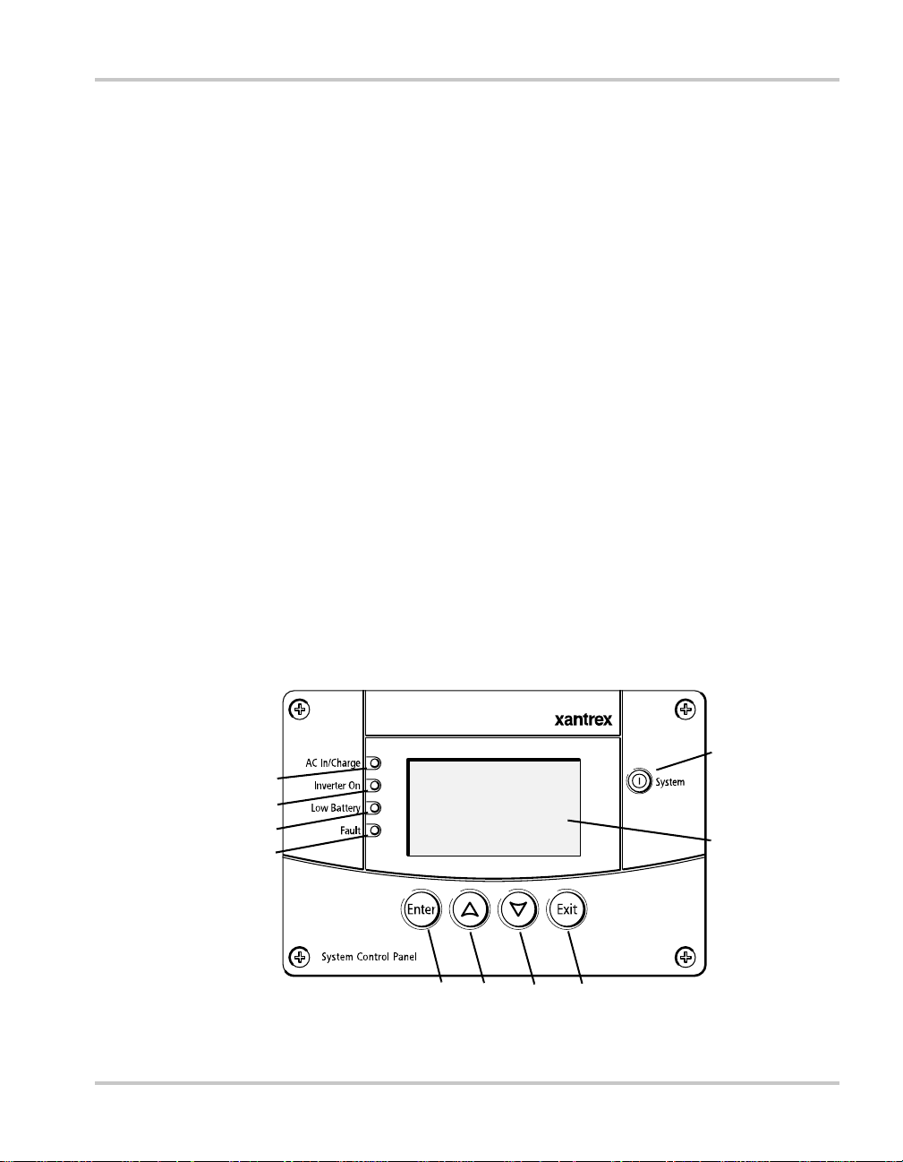
Front panel features
9
1
2
3
4
5678
Figure 1-1
975-0083-01-01 1–3
System Control Panel front panel
10
Page 16

Introduction
Feature Description
1 AC In/Charge light (green) indicates qualified AC is present at the input of an inverter/
charger or charger.
2 Inverter On light (green) indicates an inverter is using energy from batteries to provide
AC to your appliances.
3 Low Battery light (yellow) indicates that a low battery volta g e cond i ti o n exists in the
system.
4 Fault light (red) indicates a device on the network is experiencing a fault and requires user
attention and intervention.
5 Enter button
1. Confirms selection of a menu item
2. Displays the next screen
6 Up arrow button
1. Scrolls up one line of text
2. Increases a selected value
7 Down arrow button
1. Scrolls down one line of text
2. Decreases a selected value
8 Exit button
1. Cancels selection of a menu item
2. Displays the previous screen
9 System button puts all devices in the system into Safe mode (see page 5–7).
• Hold for five seconds to activate Safe mode.
• Press momentarily to clear active faults.
10 Screen shows menus, settings, and system information.
1–4 975-0083-01-01
Page 17
Physical Features
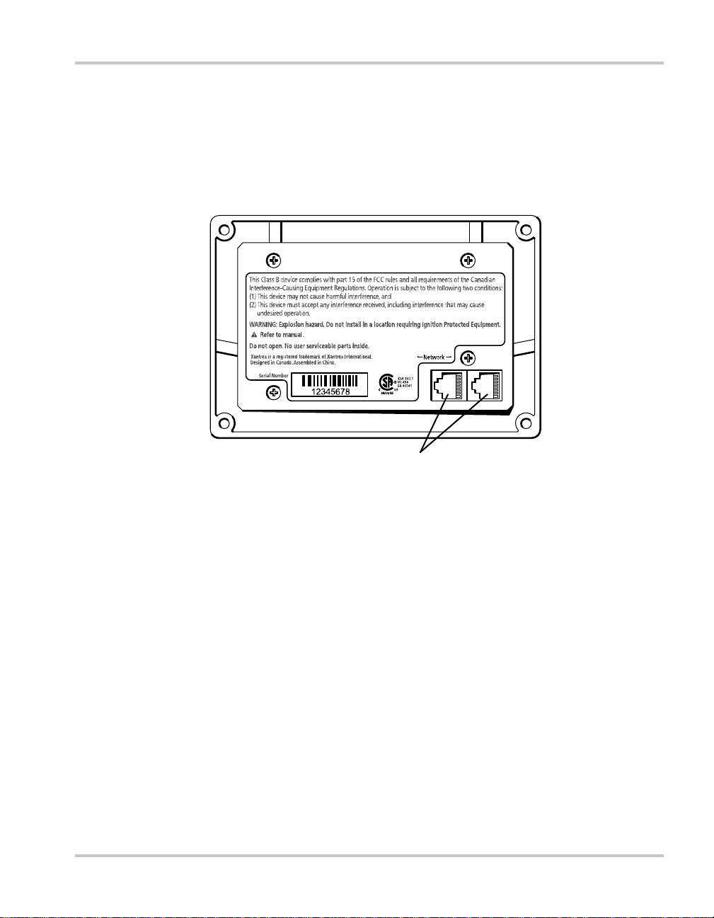
Back panel features
Connectors Two network connector inputs on the back panel let you connect the
System Control Panel to other Xanbus-enabled devices. See Figure 1-2.
Network connectors (8-pin RJ45)
Figure 1-2
975-0083-01-01 1–5
System Control Panel rear panel
Page 18
Introduction
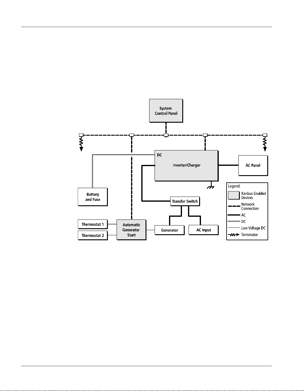
System components
System
description
Network
diagram
The Xanbus system includes the System Control Panel and other Xanbusenabled devices. Each device interacts and communicates with the other
devices.
In Figure 1-3, network connections are represented by dotted lines and
conventional electrical connections are represented by solid lines.
AC O ut
AC In
Figure 1-3
1–6 975-0083-01-01
Network diagram
Page 19

2
Installation
Chapter 2 contains information and procedures for
planning and performing a System Control Panel
installation, including:
• Materials and tools required
• Choosing a location
• Mounting the unit
• Connecting the System Control Panel to other
devices
Page 20
Installation
Installing the System Control Panel
The System Control Panel is designed to be flush mounted through an
opening in a wall and secured with four #6 screws. Use the supplied
mounting template to precisely mark the opening and screw hole
locations.
Planning an
installation
Materials and
tools required
The System Control Panel requires no connections other than the network
cables that plug into the back of the unit. Because you cannot access the
network inputs once the unit is mounted, the network cables need to be
routed through the wall before securing the System Control Panel.
CAUTION
Allow at least 2 ¼ inches (57 mm) of space behind the wall to accommodate the
depth of the unit and allow room for the network cables to bend.
Refer to the Xanbus System Installation Guide for more information about
planning and installing a network that includes the System Control Panel.
You will need these materials and tools to complete the installation:
❐ mounting template sticker (supplied)
❐ four #6 screws (supplied)
❐ Phillips head screwdriver
❐ jigsaw or small keyhole saw
❐ power drill with 1/8" bit (optional)
❐ Xantrex network cables or equivalent
Choosing a
location
2–2 975-0083-01-01
Choose a location that is easily accessible. The System Control Panel
should be mounted where it is easily visible, with unobstructed access to
the screen and push buttons.
The location should be indoors, dry, and free from corrosive or explosive
fumes.
Page 21
Installing the System Control Panel
WARNING: Fire hazard
The System Control Panel is not ignition protected. Do not install in areas
requiring ignition-protected equipment.
WARNING: Shock hazard
Before making an opening in a wall, bulkhead, or panel, ensure there is no wiring
or other obstruction within the wall.
To mount the System Control Panel:
1. Peel the backing from the supplied mounting template sticker and
place it in your chosen installation location. Use the template to mark
locations for the mounting holes and the area to be cut out.
2. Pilot-drill the mounting holes (if necessary, depending on your
mounting surface) and, using a jigsaw, cut out the hole in which the
System Control Panel will be inserted.
3. Route the network cable(s) from other Xanbus-enabled devices inside
the wall and through the opening.
CAUTION: Equipment damage
:
975-0083-01-01 2–3
Connect the System Control Panel only to other Xanbus compatible devices.
Although the cabling and connectors used in this network system are the same as
Ethernet connectors, this network is not an Ethernet system. Equipment
damage may result from attempting to connect these two different systems.
4. Connect the network cable(s) (and terminator if necessary) to either
input on the back of the System Control Panel. See Figure 2-1.
Connect one network cable and a network terminator to the System
Control Panel if it is the last device at the end of a daisy chain-type
network layout. Refer to the Xanbus System Installation Guide for
more information.
5. Place the unit in the opening and secure it with four #6 screws.
6. Peel off the protective plastic coating covering the screen and
indicator lights.
Page 22

Installation
V erifying power
is available
If network power (from an inverter/charger or external power supply) is
present, the backlight will come on and the System Control Panel will
show the startup screen (see page 3–3) for five to ten seconds, then show
the System screen.
Figure 2-1
2–4 975-0083-01-01
Connecting the network cables
Page 23

System
3
Configuration
Chapter 3 contains guidelines for using the System
Control Panel to configure another Xanbus-enabled
device on the Xanbus system.
This chapter does not recommend specific settings for
devices on your system. Refer to the Owner’s Guide or
Operation Guide for each Xanbus-enabled device for
this information.
For information about configuring the System Control
Panel itself, see Chapter 4, “Configuration”.
Page 24

System Configuration
Configuring the System
System settings are changed from the System Control Panel. You can also
use the System Control Panel to view the settings for any Xanbus-enabled
device in the Xanbus system.
Using System Control Panel buttons
The System Control Panel has four buttons for:
• moving between status screens and menus.
• highlighting settings you want to change.
• selecting values for Xanbus-enabled devices.
See Table 3-1 for the function of each button on the System Control Panel.
1234
Figure 3-1
Table 3-1
Number Button Function
1 Enter • Displays the next screen
2 Up arrow • Scrolls up one line of text
3 Down arrow • Scrolls down one line of text
4 Exit • Cancels selection of a menu item
3–2 975-0083-01-01
System Control Panel
System Control Panel buttons
• Confirms selection of a menu item
• Increases a selected value
• Decreases a selected value
• Displays the previous screen
Page 25

Menu map
e
Configuring the System
Figure 3-2 shows how the System Control Panel screens and menus are
organized. The screens and menus are described in Table 3-2.
Powe r Up
Startup screen
System screen
Standby Char gi n gInverting AC B y pa ss Equalize
Enter
Exit
Select Device
menu
Enter
Exit
Inverter/Charger
menu
Device menus
Figure 3-2
Auto Gen Start menu
The number of Device menus
System Panel menu
Clo c k me n u
System Settings
menu
depends on the number of
Xanbus-enabled devices you
have installed.
System Control Panel menu map
Optional device. This menu w
=
appear if this device is install
975-0083-01-01 3–3
Page 26

System Configuration
Table 3-2
Screen or menu Description
Startup screen Appears for a few seconds after the system is powered
System screen Displays status information for the power system. The
Select Device menu Displays a list of Xanbus-enabled devices in the
Device menus Display status information and changeable settings.
Screen and menu descriptions
Changing settings for a device
on or after the system has been reset.
System screen’s appearance varies with the status of the
inverter/charger (Standby, Inverting, Charging, AC
Bypass, or Equalize). The System screen always
features a “Menu” arrow pointing to the Enter button.
system, including the System Control Panel. The length
of this menu depends on how many devices are
installed in the system. This menu also contains the
clock menu (where you can set the time and date) and
the system settings menu (where you can change
system modes).
Changeable settings are identified by the square
brackets [ ] around values in the right-hand column (see
Figure 3-5 on page 3–6).
If you need to change a setting for a device on the system, use the buttons
on the System Control Panel to perform these three basic steps:
• Starting at the System screen, view the Select Device menu.
• Select the device from the Select Device menu.
• Select and adjust a changeable setting on the device menu.
For more information about configuring devices on the system, see the
guide for each device.
Viewing the Select Device menu
The Select Device menu lists every Xanbus-enabled device in the power
system.
To view the Select Device menu:
◆ On the System screen, press Enter.
3–4 975-0083-01-01
Page 27

menu
Configuring the System
Figure 3-3
System screen of Freedom SW 3000 (example)
Selecting the device from the Select Device menu
Use this procedure to select a device before changing a setting.
To select a device:
1. On the Select Device menu, press the down arrow button to highlight
the device you want.
InvChg
Figure 3-4
Select Device menu
2. Press Enter.
The menu for the selected device appears.
Selecting and adjusting the changeable setting
InvChg will show if there are no
compatible inverter/chargers
connected to the SCP.
Device menu You can view and change device settings from the device menu. The
number of settings on the device menu will depend on whether you have
selected to view basic or advanced menus. See “Viewing Advanced
Menus” on page 5–5.
Identifying
changeable
settings
A device menu displays a list of status information and changeable
settings. Changeable settings are enclosed in square brackets. Values in
the right-hand column without brackets are status information only. You
cannot select or change them.
Use this procedure to change any device setting.
975-0083-01-01 3–5
Page 28

System Configuration
To select and adjust a setting:
1. On the device menu, press the up arrow or down arrow button to
highlight the setting you want to change.
Figure 3-5
Device menu (System Control Panel menu used for example)
2. Press Enter to highlight the current value of that changeable setting.
Figure 3-6
Highlighting a setting
3. Press the up arrow or the down arrow button to change the value.
Hold down the button to scroll through a large range of values
quickly.
The previously set value appears with an asterisk (*) beside it.
4. Press Enter to select the value.
5. If you have another setting to change, return to step 1.
Or
If you have no more settings to change, press Exit twice to return to
the System screen.
3–6 975-0083-01-01
Page 29

4
Configuration
Chapter 4 contains information and procedures for
configuring:
• the System Control Panel on the System Panel
menu.
• the time and date on the Clock menu.
• the system mode on the System Settings menu.
Page 30

Configuration
Configuring the System Control Panel
You can configure the System Control Panel to suit your preferences and
the requirements of the Xanbus system. Some of the configurable
settings, such as the system time, affect the entire system. Other settings
affect only the System Control Panel itself, such as the brightness of the
display.
You can perform all these tasks on the System Panel menu, the Clock
menu, and the System Settings menu.
The System Panel Menu
Configuring the System Control Panel is done on the System Panel menu,
which you can view in either basic or advanced formats. See “Viewing
Advanced Menus” on page 5–5 for more information.
Basic menu The basic menu contains settings you may have to adjust routinely. The
System Control Panel shows the basic menu by default.
Advanced menu The advanced menu contains all items on the basic menu, as well as
additional configurable settings.
The advanced menu also contains a command to return it to the basic
format.
Figure 4-1 shows which items are on the basic and advanced System
Panel menus.
ADVANCED MENUBASIC MENU
System Panel
Brightness
Contrast
Button Beep
Clear Faults
Figure 4-1
4–2 975-0083-01-01
System Panel menu contents
System Panel
Brightness
Contrast
Light Timer
Button Beep
Fault Alarm
LoBatt Alarm
Set Degrees
Clear Faults
View Fault Log
View Warning Log
View Event Log
Restore Defaults
Basic Menu
Page 31

The System Panel Menu
To view the System Panel menu:
1. On the Select Device menu, use the down arrow button to highlight
System Panel.
InvChg
Figure 4-2
Highlighting System Panel
2. Press Enter.
The System Panel menu appears.
Figure 4-3
System Panel menu (basic menu shown)
To change a setting on the System Panel menu:
1. On the System Panel menu, use the up and down arrow buttons to
highlight the setting you want to change.
2. Press Enter to highlight the current value of that setting.
Figure 4-4
975-0083-01-01 4–3
Highlighting the setting
Page 32

Configuration
3. Use the up and down arrow buttons to change the value. Hold down
an arrow button to scroll through a large range of values quickly.
4. Press Enter to select the value.
5. If you have another setting to change, return to step 1.
Or
If you have no more settings to change, press Exit twice to return to
the System screen.
Basic Menu Configuration Items
The basic System Panel menu contains settings for changing the
appearance of the display. From the basic menu you can also ena ble the
low-battery warning buzzer and make the buttons beep when they are
pressed.
Menu
item Description
Brightness Adjusts the brightness of the
display to suit interior light
conditions and enhance visibility.
Contrast Adjusts the contrast of the display
to suit viewing angle and enhance
visibility.
Button
Beep
Clear
Faults
Enables buttons to beep when
pressed. This feature can be a
useful aid for confirming button
presses.
Clears active faults generated by
the System Control Panel.
Values/
Action Default
20% to 100%
(increments of
10%)
0% to 100%
(increments of
5%)
On, Off Off
Press Enter to
clear faults.
60%
60%
n/a
4–4 975-0083-01-01
Page 33

Advanced Menu Configuration Items
Advanced Menu Configuration Items
The System Panel advanced menu provides more configuration options.
The advanced menu contains all items from the basic menu, as well as
settings for turning the backlight off and selecting the temperature scale.
You can also restore default settings and view the fault and warning logs
on the advanced menu.
Menu
item Description
Light Timer Sets how long the backlight
remains on after the last button
press on the System Control Panel.
Fault Alarm Enables an alarm to sound when a
fault occurs.
LoBatt
Alarm
Set Degrees Selects the temperature scale that
View Fault
Log
View
Warning
Log
View Event
Log
Enables an alarm to sound when a
low battery voltage condition
exists.
the System Control Panel will
display.
Displays the Fault Log, containing
the last 20 System Control Panel
faults.
Displays the Warning Log,
containing the last 20 System
Control Panel warnings.
Displays the Event Log, containing
the last 20 System Control Panel
events.
Values/
Action Default
Off, 1mins–
60mins
(increments
of 1 minute)
On, Off Off
On, Off Off
Fahrenheit,
Celsius
Press Enter to
view log.
Press Enter to
view log.
Press Enter to
view log.
2mins
Fahrenheit
n/a
n/a
n/a
Restore
Defaults
Basic Menu Displays the basic menu for the
975-0083-01-01 4–5
Restores the System Control Panel
to its original factory or installer
settings. After restoring settings,
please ensure that the clock is set
correctly.
System Control Panel only.
Press Enter to
restore
defaults.
Press Enter to
view basic
menu.
n/a
n/a
Page 34

Configuration
Using the Clock Menu
Use the Clock menu to set the clock, the date, and the time format you
prefer.
The clock is listed as a separate device on the Select Device menu.
To view the Clock menu:
1. On the Select Device menu, use the up arrow or down arrow button to
highlight Clock.
InvChg
Figure 4-5
2. Press Enter.
The Clock menu appears.
Figure 4-6
Selecting the Clock menu
Clock menu
4–6 975-0083-01-01
Page 35

Clock Menu Configuration Items
Menu
item Description Values Default
Clock Menu Configuration Items
Setting the time
Set Time Sets reference time for the
power system.
Set Date Sets the reference date for
the power system.
12/24
Hour
Configures the System
Control Panel to use a 12hour clock or 24-hour
clock.
12:00 AM–11:59 PM,
00:00–23:59
month day year
(Jul 1, 04, for example)
12hr, 24hr 12hr
n/a
n/a
Because the System Control Panel keeps time for the power system,
setting the clock to the correct local time is essential for the system to
operate as expected. The clock also provides the time stamps for the
Warning, Fault, and Event logs.
When you first power up the System Control Panel, it will not begin
operating normally until you set the time.
To set the clock:
1. On the Clock menu, with Set Time highlighted, press Enter.
2. Press Enter to highlight the hour.
3. Use the up arrow or down arrow button to change the hour.
4. When the correct hour is shown, press Enter to select it and highlight
the minute.
5. Use the up arrow or down arrow button to change the minute.
6. When the correct minute is shown, press Enter to select it and
highlight the AM/PM value.
If you are using a 24-hour clock, you will return to Set Time at this
point. Proceed to step 9.
7. Use the up arrow or down arrow button to choose AM or PM.
8. When the correct value is shown, press Enter to select it and return to
the Clock menu.
9. Press Enter to return to the Select Device menu.
975-0083-01-01 4–7
Page 36

Configuration
Setting the date
If you make an error, press Exit to move back to the value you need to
reset. If you decide to abandon resetting the time, press Exit
repeatedly until you return to the Clock menu.
You can set the reference date for the Xanbus system from the Clock
menu.
To set the date:
1. On the Clock menu, use the up arrow or down arrow button to
highlight Set Date.
2. Press Enter to highlight the month.
3. Use the up arrow or down arrow button to change the month.
4. When the correct month is shown, press Enter to select it and
highlight the day.
5. Use the up arrow or down arrow button to change the day.
6. When the correct day is shown, press Enter to select it and highlight
the year.
7. Use the up arrow or down arrow button to change the year.
8. When the correct year is shown, press Enter to select it and return to
the Clock menu.
If you make an error, press Exit to move back to the value you need to
reset. If you decide to abandon resetting the date, press Exit
repeatedly until you return to the Clock menu.
4–8 975-0083-01-01
Page 37

Using the System Settings Menu
The System Settings menu displays information related to the operation
of the entire Xanbus system.
To view the System menu:
1. On the Select Device menu, use the down arrow button to highlight
System.
Using the System Settings Menu
Figure 4-7
2. Press Enter.
The System Settings menu appears.
Figure 4-8
Selecting the System Settings menu
System Settings menu
975-0083-01-01 4–9
Page 38

Configuration
System Settings Menu Configuration Items
Menu item Description Values/Action Default
Mode Displays the current system
mode as status information only.
Desired
Mode
Global
Menus
View Fault
List
View
Warning
List
View Device
Info
Sets the system mode. Operating, Safe Operating
Enables the display of advanced
or basic menus for all Xanbusenabled devices in the system,
including the System Control
Panel (see page 5–5).
Displays the Fault List screen,
which shows active faults in the
system (up to 20). See page 5–
14.
Displays the W arning List screen,
which shows active warnings in
the system (up to 20). See
page 5–10.
Displays the Device Info screen,
which lists the serial number and
software version for each
Xanbus-enabled device in the
system.
Operating, Safe n/a
Advanced,
Basic
Press Enter to
view list.
Press Enter to
view list.
Press Enter to
view screen.
Advanced
n/a
n/a
n/a
Changing the system mode
To change the System mode:
1. On the System Settings menu, with Desired Mode highlighted, press
Enter.
2. Use the up arrow or down arrow button to view the available system
modes—Operating and Safe.
3. Press Enter to select a system mode.
4. Press Exit twice to return to the System screen.
4–10 975-0083-01-01
Page 39

System Settings Menu Configuration Items
Safe mode You can also use the red System button to put the System Control Panel
and all other Xanbus-enabled devices into Safe mode only by pressing
and holding the System button for five seconds. For more information,
see “Safe mode” on page 5–7.
Viewing device information
The Device Info screen shows the serial number and firmware revision
for each Xanbus-enabled device. You cannot select or change any
information on this screen.
To view device information:
1. On the System Settings menu, press the down arrow button to
highlight View Device Info.
2. Press Enter.
The Device Info screen appears.
809-0915
1945447
F/W Rev.
2.01.00 BN0002
Figure 4-9
3. Press the down arrow button to view information for each Xanbus-
enabled device on the system.
4. Press Exit to return to the System Settings menu.
975-0083-01-01 4–11
Device Info screen (showing Auto Gen Start info)
Page 40

4–12
Page 41

5
Operation
Chapter 5 contains information and procedures for
operating the System Control Panel, including:
• Reading screens and menus
• Displaying advanced menus
• Startup behavior
• System modes
• Faults and warnings
Page 42

Operation
Reading Screens and Menus
The System Control Panel displays several different screens and menus.
The content of these screens and menus will change depending on power
system activity or the device you have selected to view information for.
During regular operation, you may need to view three screens or menus:
• System screen
• Select Device menu
• Device menu
System screen
Function The System screen is used to monitor system activity. You cannot select
or change any of the information on the System screen. If you would like
to view more detailed information for a Xanbus-enabled device, press
Enter from the System screen to go to the Select Device menu.
Appearance During normal operation, the System screen is the default screen. The
numbers and graphics on this screen provide a summary of current system
activity. The System screen’s appearance varies with the status of the
inverter/charger (Standby, Inverting, Charging, AC Bypass, or Equalize).
The basic elements appear as described in “System screen elements” on
page 5–3.
You can always identify the System screen by the Menu arrow pointing
toward the Enter button on the System Control Panel.
1
3
2
Figure 5-1
5–2 975-0083-01-01
menu
System screen (example)
Page 43

Reading Screens and Menus
Table 5-1
Number Description
System screen elements
1 Screen Title. The title is dynamic, changing as the inverter/
charger status changes.
2 Menu arrow. This arrow points to the Enter button. Pressing the
Enter button takes you to the Select Device menu.
3 Graphical status bar. This represents charger output voltage
when inverter/charger is charging.
Select Device menu
Function The Select Device menu is a list of all the Xanbus-enabled devices in your
power system, including the System Control Panel. You can select a
device from this list to view its status and change its settings.
Appearance The length of the Select Device menu will vary with the number of
Xanbus-enabled devices installed.
The System Panel, Clock, and System Settings menus are always
available from the Select Device menu, regardless of the number of
Xanbus-enabled devices installed.
To view the Select Device menu:
◆ On the System screen, press the Enter button, as indicated by the
Menu arrow.
4
1
2
3
Figure 5-2
975-0083-01-01 5–3
Select Device menu
5
Page 44

Operation
Device menu
Number Description
1 System Panel. Select this to view the System Panel menu and
configure the appearance and behavior of the System Control
Panel.
2 Clock. Select this to view the Clock menu and set the time, date,
and 12/24-hour clock format.
3 System. Select this to view the System Settings menu and change
System modes. See “Using the System Settings Menu” on page 4–
9.
4 Menu up arrow. Indicates additional menu items above the top
edge of the display.
5 Scroll bar. Moves vertically as you select each device, indicating
where you are on the menu.
Each Xanbus-enabled device has its own menu showing its status and
settings.
To view a device menu:
1. On the Select Device menu, use the up arrow or down arrow buttons
to highlight the device you want to select.
2. Press Enter.
1
Off
2
None
[ManualOff]
[On]
Figure 5-3
5–4 975-0083-01-01
Device menu (Auto Gen Start menu used as example)
3
4
5
Page 45

Viewing Advanced Menus
Table 5-2
Number Description
Device menu elements
1 Title. On a device menu, the title is not dynamic.
2 Menu items. Configurable menu items are highlighted (white
letters on black background) when selected.
3 Status value.
4 Configurable setting. Enclosed by square brackets.
5 Menu down arrow. Indicates additional menu items below
bottom edge of the display.
Viewing Advanced Menus
The System Control Panel displays device menus in two formats: basic
and advanced. The number of items on a device menu will depend on
whether you have selected to view the basic or advanced menu.
Basic menus list status information and settings you may have to adjust
routinely.
Advanced menus list all the items on the basic menu as well as additional
configuration options. Advanced menus also give you access to Fault,
Warning and Event Logs.
Displaying advanced menus for all devices
The System Control Panel shows basic menus for all devices on the
Xanbus system by default. If you would like to view advanced menus,
you must go to the System Settings menu and select Global Menus.
To view advanced menus for all devices:
1. On the Select Device menu, use the down arrow button to highlight
System.
Figure 5-4
975-0083-01-01 5–5
Highlighting System on the Select Device menu
Page 46

Operation
2. Press Enter.
The System Settings menu appears.
3. On the System Settings menu, use the down arrow button to highlight
Global Menus.
Figure 5-5
4. Press Enter.
5. Use the up or down arrow buttons to select Advanced.
6. Press Enter.
Highlighting Global Menus
Combining basic and advanced menus
You can return to viewing the basic menu for any device by selecting
Basic Menu from the advanced menu for that device.
When the System Control Panel displays basic menus for some devices
and advanced menus for other devices, you can display advanced menus
for all devices again by using the following procedure.
To view advanced menus for all devices again:
1. On the System Settings menu, use the down arrow button to highlight
Global Menus, then press Enter.
2. Use the up or down arrow buttons to select Basic.
3. Press Enter.
4. With Global Menus highlighted again, press Enter.
5. Use the up or down arrow buttons to select Advanced.
6. Press Enter.
5–6 975-0083-01-01
Page 47

Startup Behavior
When powering on the Xanbus system for the first time, the System
Control Panel displays a fault message asking you to set the clock before
proceeding. For procedures for setting the clock, see “Setting the time” on
page 4–7 and “Setting the date” on page 4–8.
System Modes
The system modes described in this section affect the performance and
behavior of the System Control Panel and all other Xanbus-enabled
devices. You will have to change the system mode when putting your
system in storage or when installing a new Xanbus-enabled device.
Changing system modes
System modes are changed using the System Settings menu (see “Using
the System Settings Menu” on page 4–9). The four system modes are:
• Operating
•Safe
Startup Behavior
Please read the section about each system mode to find out which mode is
appropriate for different conditions or situations.
Operating mode
Characteristics The basic state of the System Control Panel is Operating mode. In
Operating mode, the System Control Panel communicates with other
Xanbus-enabled devices and displays all the network information it is
configured to display.
Safe mode
Characteristics Selecting Safe mode stops the generator (if it is running) and puts the
System Control Panel (and all Xanbus-enabled devices) into Safe mode.
While in Safe mode, the System Control Panel remains powered,
“listening” to and reporting its status to the network. However, the output
power of all Xanbus-enabled devices is disabled and all inverting,
charging, and generator starting activity stops.
When to use Use Safe mode when you are adding or removing devices from the
network. Authorized service personnel must also put the System Control
Panel in Safe mode before performing software upgrades and diagnostics.
975-0083-01-01 5–7
Page 48

Operation
If the System Control Panel is powered off while in Safe mode, it will be
in Safe mode when it is powered up again.
To return to Operating mode:
◆ On the System Settings menu, under Desired Mode, select
“Operating”.
Warnings and Faults
This section describes how fault and warning messages behave, and what
you should do when they appear. For a complete list of System Control
Panel fault and warning messages along with recommended actions to
correct the fault or warning condition, please refer to Chapter 6,
“Troubleshooting”.
Important:
for all Xanbus-enabled devices in the system. For information about fault and
warnings for other devices, refer to the Troubleshooting chapter in the Owner’s
Guide or Operation Guide for each device.
Warning messages
Warning messages will appear when the System Control Panel detects a
condition that may eventually affect its continued operation. When a
warning occurs, the System Control Panel will continue operating.
However, you should consult the Troubleshooting chapter to find out
what actions you can take to prevent the warning from escalating into a
fault.
Figure 5-6
The System Control Panel displays fault and warning messages
continue cancel
System Control Panel warning message
Types There are two types of warning messages: manual and automatic. Each
differs in its behavior and appearance. For a list of System Control Panel
warnings and their associated types, refer to Chapter 6,
“Troubleshooting”.
5–8 975-0083-01-01
Page 49

If you see a warning message on the System Control Panel, you will have
to acknowledge it and (if necessary) clear it. Acknowledging the warning
allows you to continue operating the System Control Panel. Clearing the
warning message stops the warning condition from escalating into a fault.
Acknowledging warning messages
Warnings and Faults
Automatic
warnings
Manual
warnings
Acknowledging an automatic warning message removes the message
from the System Control Panel screen.
To acknowledge an automatic warning message, press Enter. After you
acknowledge the warning, the System Control Panel displays the menu
for the device that caused the warning.
The System Control Panel will remove an unacknowledged automatic
warning message from the screen after three minutes. However, if the
condition that caused the warning still exists, the warning message will
reappear.
You can view a list of the last 20 warning messages from the System
Control Panel on the Warning log. See “Viewing the System Control
Panel warning log” on page 5–10.
A manual warning message requires you to make a choice (usually by
pressing Enter for “yes” or Exit for “no”) before you can proceed
monitoring or configuring the System Control Panel. It will not disappear
after three minutes. After you respond to the warning message the System
Control Panel will clear the warning message and return to the screen it
was displaying before the warning message appeared.
Clearing warning messages
Automatic warning messages clear when the warning condition on the
System Control Panel disappears or when the criteria for clearing the
warning are met.
You can clear a manual warning message by pressing Enter or Exit in
response to the message.
Viewing multiple warning messages
If several warning messages occur before you can acknowledge or clear
them, they are displayed together on a warning list. The warning list
contains messages from every Xanbus-enabled device, not just the
System Control Panel. You can select a message from the warning list
and view its details.
975-0083-01-01 5–9
Page 50

Operation
To view a message from the warning list:
1. On the warning list, use the up arrow or down arrow button to
highlight the warning message you want to view.
2. Press Enter.
The complete warning message appea r s.
After viewing the warning message, you can return to the warning list by
pressing Exit or continue to the menu for the device that caused the
warning by pressing Enter. Each time you return to the warning list after
viewing a complete message, the viewed message is removed from the
list.
If you have left the warning list, you can view it at any time from the
System Settings menu.
To view the warning list:
1. On the Select Device menu, highlight System and press Enter.
2. On the System Settings menu, highlight View Wa rning List and press
Enter.
Viewing the System Control Panel warning log
The System Control Panel warning log displays the 20 most recent
warnings that the System Control Panel generated. These warnings can be
both active and cleared. Each warning in the log is identified by a warning
code and the time that it occurred. You may need to refer to the warning
log before consulting Chapter 6, “Troubleshooting”, or before you call
technical support.
To view the warning log:
1. On the System Panel menu, press the down arrow button to highlight
View Warning Log.
2. Press Enter.
To return to the System Panel menu:
◆ From the Warning log, press Exit.
5–10 975-0083-01-01
Page 51

Warnings and Faults
Figure 5-7
System Control Panel warning log
Viewing individual warning messages from the warning log
On the warning log, you can also select an individual warning and view
its details.
To view details for a warning:
1. Use the up arrow or down arrow button to highlight the warning
message you want to view.
2. Press Enter.
The complete message appears.
To return to the warning log:
◆ Press Exit (as indicated by the arrow marked “cancel”).
T o proceed to the device menu and reconfigur e the device to eliminate
the warning condition:
◆ Press Enter (as indicated by the arrow marked “continue”).
Fault messages
Fault messages appear when the System Control Panel’s operation is
affected by a condition that requires immediate attention. When a fault
occurs, the System Control Panel stops operating until either the fault
condition goes away or until you manually clear the fault and take action
to eliminate the fault condition.
975-0083-01-01 5–11
Page 52

Operation
continue cancel
Types of fault
messages
Figure 5-8
There are two types of System Control Panel fault messages: automatic
and manual. For a list of faults and their associated types, refer to Chapter
System Control Panel fault message
6, “Troubleshooting”.
Automatic faults clear themselves automatically if the fault condition
goes away.
Manual faults require you to clear them by:
• selecting Clear Faults on the menu of the device that generated the
fault (if the fault condition still exists, the fault message will
reappear).
• correcting the condition that caused the fault.
Viewing the System Control Panel fault log
The fault log lists the most recent System Control Panel faults, up to a
total of 20. On each line, the log shows the fault code, the date the fault
occurred, and the time the fault occurred.
To view the fault log:
1. On the System Panel advanced menu, press the down arrow button to
highlight Fault log.
2. Press Enter.
Figure 5-9
5–12 975-0083-01-01
System Control Panel fault log
Page 53

To return to the System Panel menu:
◆ Press Exit.
Viewing individual fault messages from the fault log
On the fault log, you can also select an individual fault and view its
details.
To view details for a fault:
1. Use the up arrow or down arrow button to highlight the fault message
you want to view.
2. Press Enter.
The complete fault message appears.
To return to the fault log:
◆ Press Exit (as indicated by the arrow marked “cancel”).
T o proceed to the device menu and reconfigur e the device to eliminate
the fault condition:
◆ Press Enter (as indicated by the arrow marked “continue”).
On the device menu, you can also attempt to clear the fault by selecting
Clear Faults.
Warnings and Faults
Viewing multiple fault messages
If several faults occur before you can acknowledge or clear them, the
System Control Panel displays the accumulated messages on a fault list.
The fault list displays messages from all network-enabled devices, not
just the System Control Panel. You can select a message and view
complete information for it from the fault list.
To view a message from the fault list:
1. On the fault list, use the up arrow or down arrow button to highlight
the fault message you want to view.
2. Press Enter.
The complete fault message appears.
3. To return to the fault list, press Exit.
Or
To return to the System Control Panel menu, press Enter.
Each time you return to the fault list after viewing a complete message,
the message you viewed is removed from the list.
975-0083-01-01 5–13
Page 54

Operation
You can also view the fault list at any time.
To view the fault list at any time:
1. On the Select Device menu, use the up arrow or down arrow button to
highlight System.
2. Press Enter.
3. On the System Settings menu, use the up arrow or down arrow button
to highlight View Fault List.
4. Press Enter.
5–14 975-0083-01-01
Page 55

6
Troubleshooting
Chapter 6 contains reference tables of warning and
fault messages.
Use these tables to help you identify the cause of the
fault or warning, and determine the best course of
action to correct the condition that caused the fault or
warning.
Page 56

Troubleshooting
Troubleshooting Reference
Types of Faults and Warnings
The various types of fault and warning messages behave differently, and
give you the option to treat them differently when they appear. For more
information about the types of fault and warning messages, see “Types”
on page 5–8 and “Types of fault messages” on page 5–12.
Warning Reference Table
Table 6-1
Warning
number Message Type Cause Action
W250 The selected value
W251 Please confirm
W252 Please confirm:
W254 Put system in Safe
W255 System clock not set.
Warning reference table
failed to change. Try
again.
equalization process.
Restore device’s
default settings.
mode to change
setting.
Set correct time.
Automatic A temporary
communication problem
stopped the System
Control Panel changing a
value that you entered.
Manual You have selected the
Equalize command on the
inverter/charger menu.
Manual You have selected the
Restore Defaults
command.
Manual The setting you are
changing can only be
changed when the system
is in Safe mode.
Manual On initial startup, the
clock needs to be set. The
system will not operate
correctly until it is.
Try changing the value
again.
Press Enter to begin
equalizing batteries or
Exit to return to the
inverter/charger menu.
Press Enter to restore
default settings or Exit
to cancel.
Put the system in Safe
mode, change the
setting, then return the
system to Operating
mode.
Set the clock to the
correct time.
W256 No network
connection. Check
connection to device.
6–2 975-0083-01-01
Manual The System Control Panel
has lost communications
with another device on the
network.
Check network
connection between the
System Control Panel
and the device.
Page 57

Troubleshooting Reference
Table 6-1
Warning
number Message Type Cause Action
W257 New device detected.
W501 SCP has fixed a
Warning reference table
Check device settings.
memory problem and
restored default
settings.
Manual Y ou have connected a new
device to the network or
reconnected a
disconnected device.
Manual The System Control Panel
encountered an internal
memory problem upon
startup. To remain
operational, the System
Control Panel restored its
default settings.
Acknowledge the
message and check that
the device is properly
configured.
Acknowledge the
warning and reset
configurable settings if
necessary.
975-0083-01-01 6–3
Page 58

Troubleshooting
Fault Reference Table
Table 6-2
Fault
number Message Type Cause Action
F500 Internal failure.
F501 Internal failure.
F503 Internal failure.
F504 Network not available.
Fault reference table
Service required.
Service required.
Service required.
Check connection,
clear fault.
Manual The silicon serial ID number
has failed and the System
Control Panel has gone into
Safe mode.
Manual The System Control Panel
has suffered a non-volatile
memory failure.
Manual The real-time clock in the
System Control Panel has
failed.
Automatic The System Control Panel
has lost communications
with the network because of
a faulty connection or
electronic signal disruption.
Reset the System
Control Panel. If
problem persists, call
customer service.
Reset the System
Control Panel. If
problem persists, call
customer service.
Reset the System
Control Panel by
putting it in and
taking it out of Power
Save mode. If
problem persists, call
customer service.
Check connection
between the System
Control Panel and the
network.
F505 Internal failure. See
guide.
6–4 975-0083-01-01
Manual A controller fault has
occurred and the System
Control Panel has gone into
Safe mode.
Reset the System
Control Panel. If
problem persists,
disconnect and
reconnect network
cables, or put it in and
take it out of Safe
mode.
Page 59

A
Specifications
Appendix A contains the electrical and physical
specifications for the System Control Panel.
All specifications are subject to change without notice.
Page 60

Specifications
Electrical Specifications
Nominal input network voltage 15 VDC
Minimum operating network voltage 14.25 VDC
Maximum operating network vol tage 1 5. 75 VDC
Maximum operating current 200 mA @ nominal input network voltage
Communication physical layer 2, CAN
Communication protocol Xanbus
Maximum cable length 130 ft. (40 m)
Connectors 2 RJ45—8 pins
Display dot matrix 128 × 64 LCD with white LED
Regulatory compliance CSA Certified to CSA 107.1 and UL 458,
Mechanical Specifications
backlight
including the Marine Supplement
Dimensions 6 × 4 × 1.57 " (152 × 103 × 40 mm)
Weight 0.46 lb (207 g)
Mounting flush mounted, 4 #6 screws
Environmental Specifications
Operating temperature -4 to 122 °F (-20 to 50 °C)
Storage temperature -40 to 185 °F (-40 to 85 °C)
Maximum case temperature 140 °F (60 °C)
Operating humidity 5% to 95%
Storage humidity 5% to 95%
A–2 975-0083-01-01
Page 61

Environmental Specifications
AC In/Charge
Inverter On
Low Battery
Fault
System Control Panel
Enter Exit
5.5 [140]
6 [152]
5 [127]
System
4.03
3.53
[102]
[90]
ALL DIMENSIONS IN INCHES [mm]
0.125 [3] TYP.
.40
[10]
3.04 [77]
.96 [24]
1.18 [30]
Figure A-1
System Control Panel dimensions
975-0083-01-01 A–3
Page 62

A–4
Page 63

Warranty and Return Information
Warranty
What does this warranty cover and how long does it last? This Limited Warranty is provided by
Xantrex Technology Inc. (“Xantrex”) and covers defects in workmanship and materials in your System
Control Panel. This warranty period lasts for 12 months from the date of purchase at the point of sale to
you, the original end user customer, unless otherwise agreed in writing (the “Warranty Period”). You
will be required to demonstrate proof of purchase to make warranty claims.
This Limited Warranty is transferable to subsequent owners but only for the unexpired portion of the Warranty
Period. Subsequent owners also require original proof of purchase as described in “What proof of purchase is
required?”
What will Xantrex do? During the Warranty Period Xantrex will, at its option, repair the product (if
economically feasible) or replace the defective product free of charge, provided that you notify Xantrex
of the product defect within the Warranty Period, and provided that Xantrex through inspection
establishes the existence of such a defect and that it is covered by this Limited Warranty.
Xantrex will, at its option, use new and/or reconditioned parts in performing warranty repair and
building replacement products. Xantrex reserves the right to use parts or products of original or
improved design in the repair or replacement. If Xantrex repairs or replaces a product, its warranty
continues for the remaining portion of the original Warranty Period or 90 days from the date of the
return shipment to the customer, whichever is greater. All replaced products and all parts removed from
repaired products become the property of Xantrex.
Xantrex covers both parts and labor necessary to repair the product, and return shipment to the customer
via a Xantrex-selected non-expedited surface freight within the contiguous United States and Canada.
Alaska, Hawaii and outside of the United States and Canada are excluded. Contact Xantrex Customer
Service for details on freight policy for return shipments from excluded areas.
How do you get service? If your product requires troubleshooting or warranty service, contact your
merchant. If you are unable to contact your merchant, or the merchant is unable to provide service,
contact Xantrex directly at:
Telephone: 1 800 670 0707 (toll free North America)
1 408 987 6030 (direct)
Fax: 1 800 994 7828 (toll free North America)
Email: customerservice@xantrex.com
Website: www.xantrex.com
Direct returns may be performed according to the Xantrex Return Material Authorization Policy
described in your product manual. For some products, Xantrex maintains a network of regional
Authorized Service Centers. Call Xantrex or check our website to see if your product can be repaired at
one of these facilities.
What proof of purchase is required? In any warranty claim, dated proof of purchase must
accompany the product and the product must not have been disassembled or modified without prior
written authorization by Xantrex.
975-0083-01-01 WA–1
Page 64

Warranty and Return
Proof of purchase may be in any one of the following forms:
• The dated purchase receipt from the original purchase of the product at point of sale to the end
user; or
• The dated dealer invoice or purchase receipt showing original equipment manufacturer (OEM)
status; or
• The dated invoice or purchase receipt showing the product exchanged under warranty.
What does this warranty not cover? Claims are limited to repair and replacement, or if in Xantrex's
discretion that is not possible, reimbursement up to the purchase price paid for the product. Xantrex will
be liable to you only for direct damages suffered by you and only up to a maximum amount equal to the
purchase price of the product.
This Limited Warranty does not warrant uninterrupted or error-free operation of the product or cover
normal wear and tear of the product or costs related to the removal, installation, or troubleshooting of
the customer's electrical systems. This warranty does not apply to and Xantrex will not be responsible
for any defect in or damage to:
a) the product if it has been misused, neglected, improperly installed, physically damaged or altered,
either internally or externally, or damaged from improper use or use in an unsuitable environment;
b) the product if it has been subjected to fire, water, generalized corrosion, biological infestations, or
input voltage that creates operating conditions beyond the maximum or minimum limits listed in
the Xantrex product specifications including but not limited to high input voltage from generators
and lightning strikes;
c) the product if repairs have been done to it other than by Xantrex or its autho rized service centers
(hereafter “ASCs”);
d) the product if it is used as a component part of a product expressly warranted by another manufac-
turer;
e) component parts or monitoring systems supplied by you or purchased by Xantrex at your direction
for incorporation into the product;
f) the product if its original identification (trade-mark, serial number) markings have been defaced,
altered, or removed;
g) the product if it is located outside of the country where it was purchased; and
h) any consequential losses that are attributable to the product losing power whether by product mal-
function, installation error or misuse.
Disclaimer
Product
THIS LIMITED WARRANTY IS THE SOLE AND EXCLUSIVE WARRANTY PROVIDED BY XANTREX IN CONNECTION WITH YOUR XANTREX
PRODUCT AND IS, WHERE PERMITTED BY LAW, IN LIEU OF ALL OTHER WARRANTIES, CONDITIONS, GUARANTEES,
REPRESENTATIONS, OBLIGATIONS AND LIABILITIES, EXPRESS OR IMPLIED, STATUTORY OR OTHERWISE IN CONNECTION WITH THE
PRODUCT, HOWEVER ARISING (WHETHER BY CONTRACT, TORT, NEGLIGENCE, PRINCIPLES OF MANUFACTURER'S LIABILITY,
OPERATION OF LAW, CONDUCT, STATEMENT OR OTHERWISE), INCLUDING WITHOUT RESTRICTION ANY IMPLIED WARRANTY OR
CONDITION OF QUALITY, MERCHANTABILITY OR FITNESS FOR A PARTICULAR PURPOSE. ANY IMPLIED WARRANTY OF
MERCHANTABILITY OR FITNESS FOR A PARTICULAR PURPOSE TO THE EXTENT REQUIRED UNDER APPLICABLE LAW TO APPLY TO
THE PRODUCT SHALL BE LIMITED IN DURATION TO THE PERIOD STIPULATED UNDER THIS LIMITED WARRANTY.
N NO EVENT WILL XANTREX BE LIABLE FOR: (A) ANY SPECIAL, INDIRECT, INCIDENTAL OR CONSEQUENTIAL DAMAGES, INCLUDING
I
LOST PROFITS, LOST REVENUES, FAILURE TO REALIZE EXPECTED SAVINGS, OR OTHER COMMERCIAL OR ECONOMIC LOSSES OF ANY
KIND, EVEN IF XANTREX HAS BEEN ADVISED, OR HAD REASON TO KNOW, OF THE POSSIBILITY OF SUCH DAMAGE; (B) ANY
WA–2 975-0083-01-01
Page 65

Warranty and Return
LIABILITY ARISING IN TORT, WHETHER OR NOT ARISING OUT OF XANTREX'S NEGLIGENCE, AND ALL LOSSES OR DAMAGES TO ANY
PROPERTY OR FOR ANY PERSONAL INJURY OR ECONOMIC LOSS OR DAMAGE CAUSED BY THE CONNECTION OF A PRODUCT TO ANY
OTHER DEVICE OR SYSTEM; AND (C) ANY DAMAGE OR INJURY ARISING FROM OR AS A RESULT OF MISUSE OR ABUSE, OR THE
INCORRECT INSTALLATION, INTEGRATION OR OPERATION OF THE PRODUCT BY PERSONS NOT AUTHORIZED BY XANTREX.
Exclusions
IF THIS PRODUCT IS A CONSUMER PRODUCT, FEDERAL LAW DOES NOT ALLOW AN EXCLUSION OF IMPLIED WARRANTIES. TO THE
EXTENT YOU ARE ENTITLED TO IMPLIED WARRANTIES UNDER FEDERAL LAW, TO THE EXTENT PERMITTED BY APPLICABLE LAW
THEY ARE LIMITED TO THE DURATION OF THIS LIMITED WARRANTY. SOME STATES, PROVINCES AND JURISDICTIONS DO NOT
ALLOW LIMITATIONS OR EXCLUSIONS ON IMPLIED WARRANTIES OR ON THE DURATION OF AN IMPLIED WARRANTY OR ON THE
LIMITATION OR EXCLUSION OF INCIDENTAL OR CONSEQUENTIAL DAMAGES, SO THE ABOVE LIMITATION(S) OR EXCLUSION(S) MAY
NOT APPLY TO YOU. THIS LIMITED WARRANTY GIVES YOU SPECIFIC LEGAL RIGHTS. YOU MAY HAVE OTHER RIGHTS WHICH MAY
VARY FROM STATE TO STATE, PROVINCE TO PROVINCE OR JURISDICTION TO JURISDICTION.
Return Material Authorization Policy
For those products that are not being repaired in the field and are being returned to Xantrex, before
returning a product directly to Xantrex you must obtain a Return Material Authorization (RMA) number
and the correct factory “Ship To” address. Products must also be shipped prepaid. Product shipments
will be refused and returned at your expense if they are unauthorized, returned without an RMA number
clearly marked on the outside of the shipping box, if they are shipped collect, or if they are shipped to
the wrong location.
When you contact Xantrex to obtain service, please have your instruction manual ready for reference
and be prepared to supply:
• The serial number of your product
• Information about the installation and use of the unit
• Information about the failure and/or reason for the return
• A copy of your dated proof of purchase
Record these details on page WA–4.
Return Procedure
Package the unit safely, pref erably using the original box and packing materials. Please ensure that your
product is shipped fully insured in the original packaging or equivalent. This warranty will not apply
where the product is damaged due to improper packaging.
Include the following:
• The RMA number supplied by Xantrex Technology Inc. clearly marked on the outside of the
box.
• A return address where the unit can be shipped. Post office boxes are not acceptable.
• A contact telephone number where you can be reached during work hours.
• A brief description of the problem.
Ship the unit prepaid to the address provided by your Xantrex customer service representative.
If you are returning a product from outside of the USA or Canada In addition to the above, you
MUST include return freight funds and are fully responsible for all documents, duties, tariffs, and
deposits.
975-0083-01-01 WA–3
Page 66

Warranty and Return
If you are returning a product to a Xantrex Authorized Service Center (ASC) A Xantrex return
material authorization (RMA) number is not required. However, you must contact the ASC prior to
returning the product or presenting the unit to verify any return procedures that may apply to that
particular facility and that the ASC repairs this particular Xantrex product.
Out of Warranty Service
If the warranty period for your product has expired, if the unit was damaged by misuse or incorrect
installation, if other conditions of the warranty have not been met, or if no dated proof of purchase is
available, your unit may be serviced or replaced for a flat fee.
To return your product for out of warranty service, contact Xantrex Customer Service for a Return
Material Authorization (RMA) number and follow the other steps outlined in “Return Procedure” on
page WA–3.
Payment options such as credit card or money order will be explained by the Customer Service
Representative. In cases where the minimum flat fee does not apply, as with incomplete units or units
with excessive damage, an additional fee will be charged. If applicable, you will be contacted by
Customer Service once your unit has been received.
Information About Your System
As soon as you open your System Control Panel package, record the following information and be sure
to keep your proof of purchase.
❐ Serial Number
❐ Product Number
❐ Purchased From
❐ Purchase Date
If you need to contact Customer Service, please record the following details before calling. This
information will help our representatives give you better service.
❐ Type of installation (e.g. RV, truck)
❐ Length of time SCP has been installed
❐ Battery/battery bank size
❐ Battery type (e.g. flooded, sealed gel cell, AGM)
❐ DC wiring size and length
❐ Alarm sounding?
❐ Description of indicators on front panel
❐ Appliances operating when problem occurred
______________________
809-0910
______________________
______________________
______________________
______________________
______________________
______________________
______________________
______________________
______________________
______________________
❐ Description of problem
WA–4 975-0083-01-01
______________________
Page 67

Index
Numerics
12/24 Hour 4–7
A
AC In/Charge light 1–4
advanced menu
configuration reference
displaying for all devices 5–6
viewing 4–10
4–5
B
backlight timer 4–5
basic menu
configuration reference
reverting to viewing 4–5
brightness 4–4
Button Beep 4–4
4–4
C
changing device settings 3–4
Clear Faults 4–4
Clock menu
configuration reference
using 4–6
configuration
any network-enabled device
contrast 4–4
4–7
3–2
D
date, setting 4–8
Device Information 4–10, 4–11
Device menu
defined
3–4
illustration 3–6
Down arrow button 1–4, 3–2
E
electrical specifications A–2
Enter button 1–4, 3–2
environmental specifications A–2
Event log 4–5
Exit button 1–4, 3–2
F
Fault Alarm 4–5
Fault light 1–4
Fault list 4–10, 5–13
Fault log 4–5, 5–12
fault messages
clearing
types 5–11
fault reference table 6–4
firmware revision 1–iii, 4–11
4–4
G
Global Menus
command
4–10
I
installation
connecting network cables
mounting 2–3
planning 2–2
Inverter On light 1–4
2–4
L
Light Timer 4–5
LoBatt Alarm 4–5
Low Battery light 1–4
M
mechanical specifications A–2
Menu arrow 5–3
menu map 3–3
Mode 4–10
mounting template 2–2, 2–3
Page 68

Index
N
navigation
menu map
using buttons 3–2
network cables 2–4
network connectors 1–5
network diagram 1–6
network power consumption 1–2
3–3
O
Operating mode 5–7
P
Power Save mode 5–7
proof of purchase WA–4
R
Restore Defaults 4–5
RJ45 connectors 1–5
S
Select Device menu 3–4, 5–3
Select Device menu illustration 3–5
serial number 4–10
Set Date 4–7
Set Degrees 4–5
Set Time 4–7
specifications A–2
startup behavior 5–7
startup screen 3–4
System button 1–4, 4–11
system modes 5–7
changing 4–10
System screen 3–4, 5–2
System screen illustration 3–5
U
Up arrow button 1–4, 3–2
V
verifying network power 2–4
View Event Log 4–5
View Fault Log 4–5
View Warning Log 4–5
W
Warning List 4–10
Warning log 4–5, 5–10
warning messages 5–8
warning reference table 6–2
X
Xanbus 1–2
Xantrex
web site
iv
T
time, format and setting 4–7
IX–2 975-0083-01-01
Page 69

Page 70

Xantrex Technology Inc.
1 800 670 0707 Tel toll free NA
1 360 925 5097 Tel direct
1 800 994 7828 Fax toll free NA
1 360 925 5143 Fax direct
customerservice@xantrex.com
www.xantrex.com
975-0083-01-01
Printed in China
 Loading...