

Page 1
XPower™ Inverter 450
Owner’s Manual
by
TM
Page 2

Trademarks
Xantrex and Xpower are registered trademarks of Schneider Electric Services International
sprl, registered in the United States and other countries.
Other trademarks, registered trademarks, and product names are the property of their
respective owners and are used herein for identification purposes only.
Notice of Copyright
XPower Inverter 450 Owner’s Guide Copyright © August 2010. Xantrex Technology USA Inc.
All rights reserved. No part of this document may be reproduced in any form or disclosed to
third parties without the express written consent of: Xantrex Technology USA Inc., 541 Roske
Drive, Suite A. Elkhart, Indiana, USA 46516. Xantrex Technology USA Inc. reserves the right
to revise this document and to periodically make changes to the content hereof without
obligation or organization of such revisions or changes unless required to do so by prior
arrangement.
Disclaimer
UNLESS SPECIFICALLY AGREED TO IN WRITING, XANTREX TECHNOLOGY USA INC.:
(
A) MAKES NO WARRANTY AS TO THE ACCURACY, SUFFICIENCY OR SUITABILITY OF ANY TECHNICAL OR
OTHER INFORMATION PROVIDED IN ITS MANUALS OR OTHER DOCUMENTATION;
(
B) ASSUMES NO RESPONSIBILITY OR LIABILITY FOR LOSSES, DAMAGES, COSTS OR EXPENSES,
WHETHER SPECIAL, DIRECT, INDIRECT, CONSEQUENTIAL OR INCIDENTAL, WHICH MIGHT ARISE OUT
OF THE USE OF SUCH INFORMATION. THE USE OF ANY SUCH INFORMATION WILL BE ENTIRELY AT THE
USER’S RISK; AND
(
C) REMINDS YOU THAT IF THIS MANUAL IS IN ANY LANGUAGE OTHER THAN ENGLISH, ALTHOUGH
STEPS HAVE BEEN TAKEN TO MAINTAIN THE ACCURACY OF THE TRANSLATION, THE ACCURACY
CANNOT BE GUARANTEED. APPROVED XANTREX CONTENT IS CONTAINED WITH THE ENGLISH
LANGUAGE VERSION WHICH IS POSTED AT WWW.XANTREX.COM.
Date and Revision
August 2010 Revision B
Product Number Part Number
851-0451 975-0129-01-01
Contact Information
Telephone: 1 800 670 0707 (toll free North America)
Fax: 1 800 994 7828 (toll free North America)
Email: customerservice@xantrex.com
Web: www.xantrex.com
1 408 987 6030 (direct)
Page 3

Table of Contents
1. Introduction
2. Important Safety Information
Warnings and cautions . . . . . . . . . . . . . . . . . . . . . . . . . . . . . . . . . . . . 2
Safety features . . . . . . . . . . . . . . . . . . . . . . . . . . . . . . . . . . . . . . . . . . . 6
3. Features
AC panel . . . . . . . . . . . . . . . . . . . . . . . . . . . . . . . . . . . . . . . . . . . . . . . . 7
DC panel . . . . . . . . . . . . . . . . . . . . . . . . . . . . . . . . . . . . . . . . . . . . . . . . 8
Accessories . . . . . . . . . . . . . . . . . . . . . . . . . . . . . . . . . . . . . . . . . . . . . . 9
4. Installation
Choosing a location . . . . . . . . . . . . . . . . . . . . . . . . . . . . . . . . . . . . . . 10
Mounting the inverter . . . . . . . . . . . . . . . . . . . . . . . . . . . . . . . . . . . . 11
Using the DC cable with cigarette lighter plug . . . . . . . . . . . . . . . . 12
Using the DC cable clips . . . . . . . . . . . . . . . . . . . . . . . . . . . . . . . . . . 13
Hardwiring the inverter to the battery . . . . . . . . . . . . . . . . . . . . . . . 13
Connecting the chassis ground . . . . . . . . . . . . . . . . . . . . . . . . . . . . . 16
Grounding locations . . . . . . . . . . . . . . . . . . . . . . . . . . . . . . . . . . . . . 16
Chassis ground screw . . . . . . . . . . . . . . . . . . . . . . . . . . . . . . . . . . . . 17
Testing the GFCI-protected AC outlet . . . . . . . . . . . . . . . . . . . . . . . 18
5. Operation
Operating statuses . . . . . . . . . . . . . . . . . . . . . . . . . . . . . . . . . . . . . . . 19
Inverter operation . . . . . . . . . . . . . . . . . . . . . . . . . . . . . . . . . . . . . . . 20
Battery operating time . . . . . . . . . . . . . . . . . . . . . . . . . . . . . . . . . . . . 21
6. Maintaining Battery Condition
Using vehicle batteries . . . . . . . . . . . . . . . . . . . . . . . . . . . . . . . . . . . . 23
Minimizing power draw . . . . . . . . . . . . . . . . . . . . . . . . . . . . . . . . . . . 23
Page 4

7. Troubleshooting
Common problems . . . . . . . . . . . . . . . . . . . . . . . . . . . . . . . . . . . . . . 24
Buzz in audio systems . . . . . . . . . . . . . . . . . . . . . . . . . . . . . . . . . . . 25
Television interference . . . . . . . . . . . . . . . . . . . . . . . . . . . . . . . . . . 25
Troubleshooting reference . . . . . . . . . . . . . . . . . . . . . . . . . . . . . . . . 26
8. Specifications
Electrical specifications . . . . . . . . . . . . . . . . . . . . . . . . . . . . . . . . . . 30
Physical specifications . . . . . . . . . . . . . . . . . . . . . . . . . . . . . . . . . . . 31
9. Limited Warranty
iv
Page 5

1 Introduction
Thank you for purchasing the XPower Inverter 450 (PN: 851-0451). The
XPower 450 is part of a family of advanced high-performance power
inverters from Xantrex, the leader in high-frequency inverter design.
The XPower 450 efficiently powers a wide variety of AC loads, such as
compact TVs and VCRs, laptops, camcorder and cell phone chargers,
compact fluorescent lights, and soldering irons. Depending on the
model, the XPower 450 can connect to the 12-volt battery in your vehicle
to power your devices.
The XPower 450 uses solid state power electronics that includes
automatic safety monitoring circuitry to protect it, and your battery,
from inadvertent overload conditions.
Read this guide before connecting or using the XPower 450, and save it
for future reference. The main topics in the guide are:
• Safety information (page 2)
• XPower 450 features (page 7)
• Instructions for connecting the inverter (page 10)
• Operating guidelines (page 19)
• Troubleshooting information (page 24)
• Specifications (page 30)
• Warranty and service information (page 32)
1
Page 6

2 Important Safety Information
Misusing or incorrectly connecting the XPower Inverter 450 may
damage the equipment or create hazardous conditions for users. Read
the following safety instructions and pay special attention to all Caution
and Warning statements in the guide.
Danger and Warnings identify conditions that may result in personal
injury or loss of life.
Cautions identify conditions or practices that may damage the unit or
other equipment.
Warnings and cautions
ELECTRICAL SHOCK HAZARD
• Keep children away from the XPower Inverter 450 inverter. The inverter
generates the same potentially lethal AC power as a normal household
wall outlet. Treat the outlet with respect!
• Do not use the XPower Inverter 450 in the presence of flammable fumes
or gases, such as in the bilge of a gasoline powered boat, or near propane
tanks. Do not use the XPower Inverter 450 in an enclosure containing
automotive-type, lead-acid batteries. These batteries, unlike sealed
batteries, vent explosive hydrogen gas, which can be ignited by sparks
from electrical connections.
Failure to follow these instructions will result in death or serious
injury.
2
Page 7

HEATED SURFACE HAZARD
The XPower Inverter 450 housing may become uncomfortably warm,
reaching 140° F (60° C) under extended high power operation. Ensure that
at least 2 inches (5 cm) of air surround the inverter. During operation, keep
it away from materials that may be affected by high temperatures.
Failure to follow these instructions can result in death or serious
injury.
HEATED SURFACE HAZARD
1. Batteries generate explosive gases during normal operation. Read this
guide and follow the instructions exactly before installing or using
your inverter.
2. This equipment contains components that tend to produce arcs or
sparks. To prevent fire or explosion, do not install the inverter in
compartments containing batteries or flammable materials, or in
locations that require ignition-protected equipment. These locations
include any space containing gasoline-powered machinery, fuel tanks,
as well as joints, fittings, or other connections between components of
the fuel system.
Failure to follow these instructions can result in death or serious
injury.
3
Page 8

EXPLOSION AND FIRE HAZARD
1. Follow all instructions published by the battery manufacturer and the
manufacturer of the equipment in which the battery is installed.
2. Make sure the area around the battery is well ventilated.
3. Never smoke or allow a spark or flame near the engine or batteries.
4. Use caution to reduce the risk of dropping a metal tool on the battery,
which could spark or short circuit the battery or other electrical parts
and could cause an explosion.
5. Remove metal items like rings, bracelets, and watches when working
with lead-acid batteries. Lead-acid batteries produce a short-circuit
current high enough to weld a ring or the like to metal, and thus cause
a severe burn.
6. If you need to remove a battery, always remove the ground terminal
from the battery first. Make sure all accessories are off so you don’t
cause a spark.
Failure to follow these instructions can result in death or serious
injury.
4
Page 9

RISK OF DAMAGE TO EQUIPMENT: OUTPUT IS NON-SINUSOIDAL
Some chargers for small nickel-cadmium batteries can be damaged if
connected to the XPower Inverter 450. Do not use the inverter with the
following appliances:
• Small battery-operated appliances like rechargeable flashlights, some
rechargeable shavers, and night lights that are plugged directly into an
AC receptacle to recharge.
• Battery chargers used in hand power tools. These chargers display a
warning label stating that dangerous voltages are present at the charger
battery terminals.
• Do not connect any AC load, which has its neutral conductor connected
to ground, to the XPower 450.
Failure to follow these instructions can damage the unit and/or
damage other equipment.
RISK OF DAMAGE TO THE XPOWER 450 INVERTER
• Do not insert foreign objects in the XPower 450 outlets or openings.
• Never connect the inverter to power utility AC distribution wiring.
• Do not use the XPower 450 in temperatures over 100° F (40° C).
• Do not expose the XPower 450 to water, rain, snow, or spray.
• Do not connect live AC power to the XPower 450’s AC outlets. The
inverter will be damaged even if it is switched OFF.
Failure to follow these instructions can damage the unit and/or
damage other equipment.
5
Page 10

Safety features
These advanced safety features are built into the XPower 450:
• Electronic overload protection with automatic shutdown
• Built-in internal backup DC fuse
• Low battery voltage warning followed by automatic shutdown
• High-input voltage protection with automatic shutdown
• Overheating protection with automatic shutdown
• Output short circuit protection
• GFCI (Ground Fault Circuit Interrupter) outlet
6
Page 11

3 Features
AC panel
123
Number Feature
1 GFCI AC Outlet The XPower 450 has one dual GFCI AC outlet.
2 Power Light The green
It allows you to plug in any combination of 120 V AC products with a
total continuous power consumption of 360 W.
present at the GFCI outlet and the XPower 450 is operating
normally.
POWER light indicates that AC power is
7
Page 12

Number Feature
3 Fault Light The red FAU LT light indicates that the inverter has shut
Not
shown
down because of low or high battery voltage, AC overload, or
excessively high temperatures.
Audible Alarm An audible alarm warns you of a hightemperature shutdown or of an impending low battery voltage
shutdown.
DC panel
1
2
3
Number Feature
1 On/Off Switch The two positions on the On/Off switch are
indicated as follows:
= Off (Standby) and = On.
When the inverter is connected to a DC power source and the switch
is on, AC power is available at the AC outlet.
8
5
4
Page 13

Number Feature
2 Cooling Fan When output power is greater than approximately
3 Chassis Ground Screw During installation, the chassis ground
4 Negative DC Terminal Connection point to the negative battery
5 Positive DC Terminal Connection point to the positive battery
50 W, the fan turns on to help maintain optimum operating
temperature.
screw is connected to a chassis ground wire that connects to the
grounding point on your boat or vehicle.
terminal.
terminal.
Accessories
There are no accessories for this product.
9
Page 14

4 Installation
Installing the XPower 450 requires five steps:
1. Choosing a location
2. Mounting the inverter
3. Connecting DC power to the inverter using either:
• the cigarette lighter plug (if supplied).
• DC cable clips and a battery (if supplied).
• hardwiring the inverter to the battery.
4. Connecting the chassis ground
5. Testing the AC outlet
Choosing a location
For best performance, choose a location that is:
• Dry Do not expose the inverter to water drip or spray.
• Cool Operate the inverter in ambient temperatures between 0° C
and 40° C (32° F and 100° F). Keep it away from heating vents and
direct sunlight.
• Well ventilated For proper cooling, allow at least 5 cm (2 in.) of
clearance around the inverter.
• Clean and free of dust and dirt Choose a location that is free of
any debris that could get into the inverter.
10
Page 15

Mounting the inverter
Before mounting the inverter, please see “Choosing a location”.
To mount the inverter:
1. Make sure the ON/OFF switch is in the OFF position.
2. Select an appropriate mounting location and orientation. The
inverter must be oriented in one of the following ways:
• Horizontally on a vertical surface. (Do not mount with the fan
pointing up or down.)
• On or under a horizontal surface
3. Hold the inverter against the mounting surface, mark the positions
of the mounting screws, and then remove the inverter.
4. Pilot drill the four mounting holes.
5. Fasten the inverter to the mounting surface using corrosionresistant #8 screws.
11
Page 16

Using the DC cable with cigarette lighter plug
Due to the limitations of 12 V outlets in boats and vehicles, the XPower
450 should be used with the DC cable with cigarette lighter plug (if
supplied) only to supply AC power to products that require 150 W (about
1.3 A) or less. If your application requires more than 150 W or has a high
start-up surge, see Using the DC cable clips.
REVERSE POLARITY DAMAGE
A reverse polarity connection (positive to negative) may damage the power
inverter. Damage caused by a reverse polarity connection is not covered
under warranty.
Failure to follow these instructions can damage the unit and/or
damage other equipment.
1. Attach the ring-type connector marked with red to the positive (+)
DC terminal on the power inverter, and attach the ring connector
marked with black to the negative (–) DC terminal.
2. With star washer in place, tighten the nut on each DC terminal by
hand until it is snug. Do not over-tighten.
3. Insert the plug of this cable into the 12 V outlet and switch the power
inverter “ON”.
4. When the power inverter is not in use, unplug it from the 12 V outlet
to prevent slight discharge of the battery.
12
Page 17

Using the DC cable clips
By directly connecting the power inverter to a 12 V battery using the DC
cable clips (if supplied), you can operate products with power
requirements up to 360 W continuous.
1. Follow steps 1 and 2 under “Using the DC cable with cigarette lighter
plug” to attach the ring-type connectors.
2. Attach the negative (black) clip to the negative (–) battery terminal.
3. Attach the positive (red) clip to the positive (+) battery terminal.
Make sure both clips are securely connected to the battery terminals,
as a loose connection will cause the voltage to drop and may cause
the cables to overheat, resulting in equipment damage or fire.
4. Switch the power inverter “ON”.
5. When the power inverter is not in use, disconnect the DC cable clips
from the battery to prevent slight discharge of battery.
Hardwiring the inverter to the battery
A hardwiring illustration is shown in Figure 1.
SHOCK AND FIRE HAZARD
Have a qualified installer perform a hardwired installation.
Failure to follow these instructions can result in death or serious
injury.
13
Page 18

5
4
–
1
+
3
2
Figure 1
1. XPower Inverter 450 4. 12 V battery
2. 8 AWG red wire from the positive
inverter terminal to the positive battery
terminal (via the fuse)
3. 60 A automotive or marine fuse
Hardwiring the inverter to a 12 V battery
5. 8 AWG black wire from the
negative inverter terminal to the
negative battery terminal
To hardwire the inverter to a 12 V battery:
1. Make sure the power inverter’s ON/OFF switch is in the OFF
position.
2. Use an 8 AWG (or heavier) wire to a maximum total length of 2 m
(6.5').
3. Install a 60 A automotive fuse in the positive (red) wire, close to the
end that will attach to the battery.
14
Page 19

4. Solder or crimp the heavy-duty terminals to the positive and
negative wires. Use terminals that mate properly with the battery
terminals or existing battery cable clamps.
INVERTER DAMAGE
• Reversing the positive and negative battery cables will damage the
inverter and will void your warranty.
• Before connecting the inverter to the battery, double check the
connections: The red wire must be connected to the red terminal on the
inverter and the positive (+) terminal on the battery; the black wire
must be connected to the black terminal on the inverter and the
negative (–) terminal on the battery.
Failure to follow these instructions can damage the unit and/or
damage other equipment.
5. Remove the nuts from the DC terminals on the inverter.
6. Place the red ring connector on the red (positive +) DC terminal on
the inverter. With star washer in place, screw the red nut on until it
is snug. Do not over-tighten.
7. Fasten the positive terminal (red wire) to the positive battery post.
8. Fasten the negative terminal (black wire) to the negative battery
post.
9. Place the black ring connector on the black (negative –) DC terminal
on the inverter. With star washer in place, screw the black nut on
until it is snug. Do not over-tighten.
10. Switch the inverter’s ON/OFF switch to the “ON” position. The
green power light comes on, and AC power is available at the outlet.
15
Page 20

Connecting the chassis ground
ELECTRICAL SHOCK HAZARD
Never operate the inverter without properly connecting the chassis ground.
An electrical shock hazard could result from improper grounding.
Failure to follow these instructions will result in death or serious
injury.
The inverter has a chassis ground terminal screw on the rear panel
marked . Follow the guidelines under “Grounding locations” to
connect the inverter’s chassis to the ground.
Grounding locations
You must connect the chassis ground terminal to a grounding point. The
grounding point varies depending on where you install the inverter.
Follow the instructions that correspond to your type of installation.
To connect the chassis ground terminal to a grounding point:
• Connect the chassis ground screw to the boat’s DC ground bus or
engine negative bus using recommended copper wire (if insulated,
use green insulation with or without one or more yellow stripe) or
larger.
• Connect the chassis ground screw to the vehicle’s chassis using
recommended copper wire (if insulated, use green insulation with or
without one or more yellow stripe) or larger.
16
Page 21
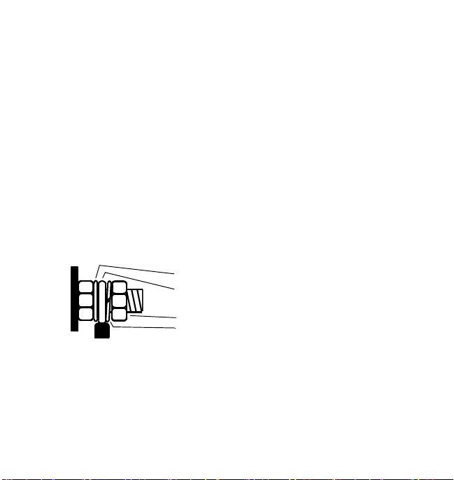
Chassis ground screw
We recommend that you attach the cable to the chassis ground screw
with a ring terminal. This procedure will ensure that the wire does not
slip off the chassis ground screw. See Figure 2.
To connect the cable to the chassis ground screw:
1. Make sure the inverter’s ON/OFF switch is in the OFF position.
2. Strip 1/2" (13 mm) to 3/4" (19 mm) of insulation from one end of
each cable.
3. Attach the ring connector that will join the cable to the chassis
ground screw. The connector you use must create a permanent, lowresistance connection.
4. Remove the chassis ground nut and split washer from the chassis
ground screw.
5. Place the ring connector over the chassis ground screw and against
the flat washer.
6. Replace the split washer and tighten the chassis ground nut.
flat washer
ring connector
chassis ground nut
split washer
Figure 2
Connecting the grounding cable
17
Page 22

Testing the GFCI-protected AC outlet
The outlet on the XPower 450 is a Ground Fault Circuit Interrupter
(GFCI) outlet. A GFCI outlet protects you against hazardous electrical
shocks that could be caused by dampness, faulty mechanism, worn
insulation, and so on. You might still feel shock, but the GFCI should cut
it off quickly enough so an adult in normal health is not seriously injured
(infants and small children may still be affected).
Test the GFCI periodically to make sure it is operating correctly.
To test the GFCI protection:
1. Switch the power inverter “ON”.
2. Plug a test lamp into the outlet.
3. Push the “TEST” button.
The “RESET” button should pop out and the power should turn off
(the lamp should go out). If the lamp remains lit, or if the “RESET”
button does not pop out, take the product back to the store where it
was purchased and get a replacement or contact Xantrex for under
warranty replacement.
If the GFCI trips by itself at any time, reset it and perform the preceding
test.
18
Page 23

5 Operation
Operating statuses
This section describes normal operation as well as problems that could
occur when you use the inverter. If you have a problem, see
“Troubleshooting” on page 24.
The XPower Inverter 450 is capable of continuously powering most
120 V AC products that use 360 W or less. Its AC output waveform, called
“modified sine wave,” is designed to function similarly to the sine wave
shape of utility power.
The power, or “wattage,” rating of AC products is the average power they
use. When most AC products are first switched on, they initially consume
more power than their power rating. TVs, monitors, and electric motors
are examples of products that have high “surge” requirements at start up.
Although the XPower 450 can supply momentary surge power as high as
700 W, occasionally some products rated less than 360 W may exceed its
surge capabilities and trigger its safety overload shutdown feature. If this
problem occurs when attempting to operate several AC products at the
same time, first try switching on the inverter with all AC products
switched off, then one by one switch each on, starting with the high surge
product first.
19
Page 24

Inverter operation
1. When properly connected to a 12 V outlet or battery, turning the
inverter switch “ON” will illuminate the green “POWER” light, and
deliver AC power to the outlet(s).
2. Plug the AC product(s) you wish to operate into the GFCI outlet(s)
and switch them on, one at a time.
3. As the battery is used, voltage begins to fall. When the XPower 450
senses that the voltage at its DC input has dropped to 11 V, an
audible alarm sounds. This alarm warning allows time for
computers or other sensitive devices to be shut down.
4. If the audible alarm is ignored, the XPower 450 will automatically
shut down when the battery voltage drops to 10.5 V. This autoshutdown prevents the battery from being damaged. After autoshutdown, the red “FAULT” light illuminates and the alarm will
sound.
IMPORTANT: Boat or vehicle starting batteries are designed to provide
brief periods of very high current needed for engine starting, and are not
intended for constant deep discharge. Regularly operating the XPower
450 from a boat battery until the low voltage alarm sounds will shorten
the life of the battery. Consider connecting the power inverter to a
separate deep-cycle battery if you will be frequently running electrical
products for extended periods of time.
5. If an AC product rated higher than 360 W (or which draws excessive
surge power) is connected, the XPower 450 will shut down. The red
“FAULT” light will turn on.
6. If the XPower 450 exceeds a safe operating temperature due to
insufficient ventilation or a high-temperature environment, it will
automatically shut down. The red “FAULT” light will turn on and the
audio warning will sound.
20
Page 25

7. Should a defective battery charging system cause the battery voltage
to rise to dangerously high levels, the XPower 450 will automatically
shut down. The red “FAULT” light will turn on.
INVERTER DAMAGE
Although the XPower 450 incorporates protection against over-voltage, it
may still be damaged if the input voltage exceeds 16 V. Damage may void
the warranty.
Failure to follow these instructions can damage the unit and/or
damage other equipment.
8. The cooling fan on the unit is designed to operate only when output
power is greater than approximately 50 W. When inverter is turned
on, the fan may operate momentarily.
9. In the event of an overload, low battery voltage or overheating, the
XPower 450 will automatically shut down.
Battery operating time
Operating time will vary depending on the charge level of the battery, its
capacity and the power level drawn by the particular AC load. With a
typical boat battery (60 Ah) and a 100 W load (such as a small TV), an
operating time of 2 to 3 hours or more can be expected.
When using a boat battery as a power source, it is strongly recommended
to start the boat every hour or two to recharge the battery before its
capacity drops too low. The XPower 450 can operate while the engine is
21
Page 26

running, but the normal voltage drop that occurs during starting of the
engine may trigger the inverter’s low voltage shutdown feature. Because
the power inverter draws less than 0.25 A with the ON/OFF switch in the
“ON” position and with no AC products connected, it has minimal impact
on battery operating times.
The battery operating time of the XPower 450 depends on the charge
level of the battery, battery capacity, and the amount of power drawn by
the AC loads you are operating. With a typical vehicle battery, you can
expect the following:
Table 1
Battery Operating Times
Load Sample Appliance Operating Time
(continuous)
50 watts CD player 5–6 hours
100 watts small TV 3–4 hours
200 watts computer system 1–2 hours
22
Page 27

6 Maintaining Battery Condition
Here are some guidelines that will help to preserve your battery.
Using vehicle batteries
• Vehicle batteries are not designed for repeated deep-discharge
cycles, and constantly recharging a vehicle’s battery will shorten its
life. Therefore, when you are using a vehicle battery as a power
source, start the vehicle every hour or two to recharge the battery.
•The XPower 450 will operate while the engine is running, but the
voltage drop that occurs when the engine starts may trigger a low
voltage shutdown.
• Vehicle batteries are designed to provide brief periods of very high
current needed for engine starting. They are not intended for
constant deep discharge. Regularly operating the XPower 450 from
a vehicle battery until the low voltage alarm sounds will shorten the
life of the battery. Consider connecting the XPower 450 to a separate
deep discharge type battery if you will be frequently running
electrical products for extended periods of time.
Minimizing power draw
• If you are not going to use the XPower 450 for more than a week,
turn off the On/Off switch. The inverter draws less than 0.2 amps
when the On/Off switch is on and no load is connected, but it will
eventually discharge the battery.
23
Page 28

7Troubleshooting
This section will help you identify the source of most problems that can
occur with the XPower 450.
If you have a problem with the inverter, please review this section before
contacting Xantrex Customer Service. If you are unable to solve a
problem and need to contact Xantrex, please prepare for the call by
writing down the following details:
• When and where purchased
• Inverter’s serial number
• How long the inverter has been in use
• Where it is installed
• Appliances operating when the problem occurred
• A brief description of the problem
Common problems
ELECTRICAL SHOCK HAZARD
Do not dismantle the XPower 450. It does not contain any user-serviceable
parts. Attempting to service the inverter yourself could result in an
electrical shock or burn.
Failure to follow these instructions will result in death or serious
injury.
24
Page 29

Buzz in audio systems
Some inexpensive stereo systems have inadequate internal power supply
filtering and buzz slightly when powered by the XPower 450. The best
solution is to use an audio system with a good quality filter.
Television interference
The XPower 450 is shielded to minimize interference with TV signals. If
TV signals are weak, you may see interference in the form of lines
scrolling across the screen. Try one of these suggestions to minimize or
eliminate the problem:
• Increase the distance between the XPower 450 and the TV, antenna,
and cables.
• Adjust the orientation of the XPower 450, television, antenna, and
cables.
• Maximize TV signal strength by using a better antenna, and use
shielded antenna cable where possible.
• Try a different TV. Different models vary considerably in their
susceptibility to interference.
25
Page 30

Troubleshooting reference
This section describes problems, their symptoms, possible causes, and
specific remedies.
PROBLEM: AC product will not operate, no inverter warning
lights are ON.
Possible cause Remedy
Battery is defective. Check battery and replace if required.
Inverter has been connected with
reverse DC input polarity.
Loose cable connections. Check cables and connections. Tighten
PROBLEM: Inverter will run some small loads, but not larger
ones.
Possible cause Remedy
Voltage drop across DC cables. Shorten cables or use heavier cables.
26
Check connection to battery. Probable
inverter damage has occurred. Have
unit repaired (not covered by
warranty).
as required.
Page 31

PROBLEM: Measured inverter output is too low.
Possible cause Remedy
Standard "average reading" AC
voltmeter used to measure output
voltage, resulting in an apparent
reading 5 to 15 V too low.
Battery voltage is too low. Recharge battery.
Inverter’s "modified sine wave" output
requires "true RMS" voltmeter for
accurate measurements.
PROBLEM: Alarm is sounding.
Possible cause Remedy
Low voltage shutdown or thermal
shutdown has occurred.
Shorten cables or use heavier cables.
Recharge the battery. Allow the unit to
cool. Improve air circulation around
the unit. Move the unit to a cooler
environment. Reduce the load if
continuous operation is required.
27
Page 32

PROBLEM: Battery run time is less than expected.
Possible cause Remedy
The AC load power consumption is
higher than rated.
The battery is old or defective. Replace the battery.
The battery is not being charged
properly.
Power dissipation in DC cables. Use shorter/heavier DC cables.
Use a larger battery to make up for the
increased power requirement.
Some chargers are not able to fully
recharge a battery. Make sure you use a
powerful charger.
28
Page 33

PROBLEM: AC product will not operate, red “FAULT” light
ON.
Possible cause Remedy
AC product(s) connected is/are rated
at more than the inverter’s continuous
power rating; overload shutdown has
occurred.
AC product is rated less than the
inverter’s continuous power rating;
high starting surge has caused
overload shutdown.
Battery is discharged (alarm is
sounding).
The inverter has overheated due to
poor ventilation and has shut down.
Input voltage is greater than 15 V. Verify charging system is properly
Use a product with a power rating less
than the inverter’s continuous power
rating.
Product exceeds inverter’s surge
capability. Use a product with starting
surge power within the inverter’s
capability.
Recharge battery.
Switch inverter “OFF” and allow to
cool for 15 min. Clear blocked fan or
remove objects covering unit. Move the
inverter to a cooler place. Reduce load
if continuous operation is required.
Restart.
regulated and battery is 12 V nominal.
Consumer hotline: 1-800-670-0707
29
Page 34

8 Specifications
Specifications are subject to change without notice.
Electrical specifications
AC output voltage (nominal) 120 V AC
DC input voltage range 10.5–15.5 V DC
Continuous AC output power 360 W
5 min. AC output power 450 W
Maximum AC output surge power 700 W
AC output frequency 60 ± 4 Hz
AC output waveform Modified sine wave
Battery drain with no AC current load
(at 12 V input)
Efficiency (maximum) 90%
Ambient operating temperature range 32–104 °F
Low battery alarm trigger point
(nominal)
30
0.25 A
(0–40 °C)
11.0 V
Page 35

Low battery shutdown point (nominal) 10.5 V
Overheat shutdown Yes, automatic
Overload shutdown Yes, automatic
High battery shutdown point (nominal) 15.5 V
Physical specifications
Dimensions (L x W x H)
Weight 2.25 lb. / 1020 g
Product number 851-0451
8.3 × 4.5 × 2.6
211 × 115 × 65 mm
"
31
Page 36

9 Limited Warranty
Warranty
What does this warranty cover? This Limited Warranty is provided by Xantrex Technology USA Inc. ("Xantrex")
and covers defects in workmanship and materials in your XPower Inverter 450. This warranty period lasts for 1 year
from the date of purchase at the point of sale to you, the original end user customer, unless otherwise agreed in writing
(the “Warranty Period”). You will be required to demonstrate proof of purchase to make warranty claims.
This Limited Warranty is transferable to subsequent owners but only for the unexpired portion of the Warranty Period.
Subsequent owners also require original proof of purchase as described in "What proof of purchase is required?"
What will Xantrex do? During the Warranty Period Xantrex will, at its option, repair the product (if economically
feasible) or replace the defective product free of charge, provided that you notify Xantrex of the product defect within
the Warranty Period, and provided that Xantrex through inspection establishes the existence of such a defect and that it is
covered by this Limited Warranty.
Xantrex will, at its option, use new and/or reconditioned parts in performing warranty repair and building replacement
products. Xantrex reserves the right to use parts or products of original or improved design in the repair or replacement.
If Xantrex repairs or replaces a product, its warranty continues for the remaining portion of the original Warranty Period
or 90 days from the date of the return shipment to the customer, whichever is greater. All replaced products and all parts
removed from repaired products become the property of Xantrex.
Xantrex covers both parts and labor necessary to repair the product, and return shipment to the customer via a Xantrex
selected non-expedited surface freight within the contiguous United States and Canada. Alaska, Hawaii and outside of
the United States and Canada are excluded. Contact Xantrex Customer Service for details on freight policy for return
shipments from excluded areas.
How do you get service? If your product requires troubleshooting or warranty service, contact your merchant. If you
are unable to contact your merchant, or the merchant is unable to provide service, contact Xantrex directly at: 1 408 987
6030 (direct telephone) or customerservice@xantrex.com (Email).
Direct returns may be performed according to the Xantrex Return Material Authorization Policy described in your
product manual. For some products, Xantrex maintains a network of regional Authorized Service Centers. Call Xantrex
or check our website to see if your product can be repaired at one of these facilities.
What proof of purchase is required? In any warranty claim, dated proof of purchase must accompany the product
and the product must not have been disassembled or modified without prior written authorization by Xantrex.
Proof of purchase may be in any one of the following forms:
• The dated purchase receipt from the original purchase of the product at point of sale to the end user; or
• The dated dealer invoice or purchase receipt showing original equipment manufacturer (OEM) status; or
• The dated invoice or purchase receipt showing the product exchanged under warranty.
What does this warranty not cover? Claims are limited to repair and replacement, or if in Xantrex's discretion that is
not possible, reimbursement up to the purchase price paid for the product. Xantrex will be liable to you only for direct
damages suffered by you and only up to a maximum amount equal to the purchase price of the product.
This Limited Warranty does not warrant uninterrupted or error free operation of the product or cover normal wear and
tear of the product or costs related to the removal, installation, or troubleshooting of the customer's electrical systems.
This warranty does not apply to and Xantrex will not be responsible for any defect in or damage to:
a) the product if it has been misused, neglected, improperly installed, physically damaged or altered, either internally or
externally, or damaged from improper use or use in an unsuitable environment;
b)the product if it has been subjected to fire, water, generalized corrosion, biological infestations, or input voltage that
creates operating conditions beyond the maximum or minimum limits listed in the Xantrex product specifications
including but not limited to high input voltage from generators and lightning strikes;
32
Page 37

c) the product if repairs have been done to it other than by Xantrex or its authorized service centers (hereafter "ASCs");
d)the product if it is used as a component part of a product expressly warranted by another manufacture r;
e) component parts or monitoring systems supplied by you or purchased by Xantrex at your direction for incorporation
into the product;
f) the product if its original identification (trade-mark, serial number) markings have been defaced, altered, or removed;
g)the product if it is located outside of the country where it was purchased; and
h)any consequential losses that are attributable to the product losing power whether by product malfunction, installation
error or misuse.
Product Disclaimer
THIS LIMITED WARRANTY IS THE SOLE AND EXCLUSIVE WARRANTY PROVIDED BY XANTREX IN CONNECTION WITH YOUR
XANTREX PRODUCT AND IS, WHERE PERMITTED BY LAW, IN LIEU OF ALL OTHER WARRANTIES, CONDITIONS, GUARANTEES,
REPRESENTATIONS, OBLIGATIONS AND LIABILITIES, EXPRESS OR IMPLIED, STATUTORY OR OTHERWISE IN CONNECTION WITH
THE PRODUCT, HOWEVER ARISING (WHETHER BY CONTRACT, TORT, NEGLIGENCE, PRINCIPLES OF MANUFACTURER'S
LIABILITY, OPERATION OF LAW, CONDUCT, STATEMENT OR OTHERWISE), INCLUDING WITHOUT RESTRICTION ANY IMPLIED
WARRANTY OR CONDITION OF QUALITY,
MERCHANTABILITY OR FITNESS FOR A PARTICULAR PURPOSE. ANY IMPLIED WARRANTY OF
MERCHANTABILITY OR FITNESS FOR A PARTICULAR PURPOSE TO THE EXTENT REQUIRED UNDER
APPLICABLE LAW TO APPLY TO THE PRODUCT SHALL BE LIMITED IN DURATION TO THE PERIOD STIPULATED UNDER THIS
LIMITED WARRANTY. IN NO EVENT WILL XANTREX BE LIABLE FOR: (A) ANY SPECIAL, INDIRECT, INCIDENTAL OR
CONSEQUENTIAL DAMAGES, INCLUDING LOST PROFITS, LOST REVENUES, FAILURE TO REALIZE EXPECTED SAVINGS, OR OTHER
COMMERCIAL OR ECONOMIC LOSSES OF ANY KIND, EVEN IF XANTREX HAS BEEN ADVISED, OR HAD REASON TO KNOW, OF THE
POSSIBILITY OF SUCH DAMAGE; (B) ANY LIABILITY ARISING IN TORT, WHETHER OR NOT ARISING OUT OF XANTREX'S
NEGLIGENCE, AND ALL LOSSES OR DAMAGES TO ANY PROPERTY OR FOR ANY PERSONAL INJURY OR ECONOMIC LOSS OR
DAMAGE CAUSED BY THE CONNECTION OF A PRODUCT TO ANY OTHER DEVICE OR SYSTEM; AND (C) ANY DAMAGE OR INJURY
ARISING FROM OR AS A RESULT OF MISUSE OR ABUSE, OR THE INCORRECT INSTALLATION, INTEGRATION OR OPERATION OF
THE PRODUCT BY PERSONS NOT AUTHORIZED BY XANTREX.
Exclusions
IF THIS PRODUCT IS A CONSUMER PRODUCT, FEDERAL LAW DOES NOT ALLOW AN EXCLUSION OF IMPLIED WARRANTIES. TO
THE EXTENT YOU ARE ENTITLED TO IMPLIED WARRANTIES UNDER FEDERAL LAW, TO THE EXTENT PERMITTED BY APPLICABLE
LAW THEY ARE LIMITED TO THE DURATION OF THIS LIMITED WARRANTY. SOME STATES, PROVINCES AND JURISDICTIONS DO
NOT ALLOW LIMITATIONS OR EXCLUSIONS ON IMPLIED WARRANTIES OR ON THE DURATION OF AN IMPLIED WARRANTY OR ON
THE LIMITATION OR EXCLUSION OF INCIDENTAL OR CONSEQUENTIAL DAMAGES, SO THE ABOVE LIMITATION(S) OR
EXCLUSION(S) MAY NOT APPLY TO YOU. THIS LIMITED WARRANTY GIVES YOU SPECIFIC LEGAL RIGHTS. YOU MAY HAVE
OTHER RIGHTS WHICH MAY VARY FROM STATE TO STATE, PROVINCE TO PROVINCE OR JURISDICTION TO JURISDICTION.
Return Material Authorization Policy
Before returning a product directly to Xantrex you must obtain a Return Material Authorization (RMA) number and the
correct factory "Ship To" address. Products must also be shipped prepaid. Product shipments will be refused and
returned at your expense if they are unauthorized, returned without an RMA number clearly marked on the outside of the
shipping box, if they are shipped collect, or if they are shipped to the wrong location.
When you contact Xantrex to obtain service, please have your instruction manual ready for reference and be prepared to
supply:
• The serial number of your product
• Information about the installation and use of the unit
• Information about the failure and/or reason for the return
• A copy of your dated proof of purchase
33
Page 38

Return Procedure
1. Package the unit safely, preferably using the original box and packing materials. Please ensure that your product is
shipped fully insured in the original packaging or equivalent. This warranty will not apply where the product is
damaged due to improper packaging.
2. Include the following:
• The RMA number supplied by Xantrex Technology USA Inc. clearly marked on the outside of the box.
• A return address where the unit can be shipped. Post office boxes are not acceptable.
• A contact telephone number where you can be reached during work hours.
• A brief description of the problem.
3. Ship the unit prepaid to the address provided by your Xantrex customer service representative.
If you are returning a product from outside of the USA or Canada In addition to the above, you MUST include
return freight funds and are fully responsible for all documents, duties, tariffs, and deposits.
Out of Warranty Service
If the warranty period for your XPower Inverter 450 has expired, if the unit was damaged by misuse or incorrect
installation, if other conditions of the warranty have not been met, or if no dated proof of purchase is available, your
inverter may be serviced or replaced for a flat fee.
To return your XPower Inverter 450 for out of warranty service, contact Xantrex Customer Service for a Return Materi al
Authorization (RMA) number and follow the other steps outlined in “Return Procedure” above.
Payment options such as credit card or money order will be explained by the Customer Service Representative. In cases
where the minimum flat fee does not apply, as with incomplete units or units with excessive damage, an additional fee
will be charged. If applicable, you will be contacted by Customer Service once your unit has been received.
34
Page 39

Page 40

t 1-800-670-0707 (toll free in North America)
1-408-987-6030 (direct)
f 1-800-994-7828 (toll free in North America)
e CustomerService@xantrex.com
www.xantrex.com
975-0129-01-01 REV B
 Loading...