

Page 1
PN 270-0697-01-01
30
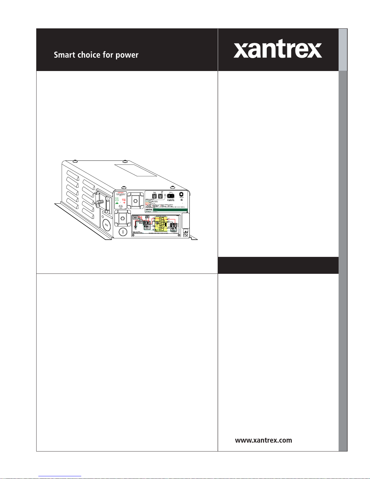
RV2012GS
RV GS Series
Inverter/Charger
PN 3341
RV2012GS-15/20B
RV2012GS-20B
Battery Type = LIQUID LEAD ACID
Bat Capacity = AUTO
Auto LBCO = ON
Search sense = DEFEAT
Shore Power = 30A
VAC Dropout = 40VAC
Charge Rate = 80%
This Inverter/Charger has been factory
programmed to the following settings:
RV2512GS
RV3012GS
Owner’s Manual
Page 2

Page 3

About This Manual
Purpose
The purpose of this Owner’s Manual is to provide explanations and procedures for
installing, operating, and troubleshooting the RV Series Inverter/Charger.
Scope
The Manual provides safety guidelines, detailed planning and setup information,
procedures for installing the inverter, as well as information about operating and
troubleshooting RV Series Inverter/Charger models RV2012GS, RV2012GS-15/
20B, RV2012GS-20B, RV2512GS, RV3012GS. It does not provide details about
particular brands of batteries. You need to consult individual battery
manufacturers for this information.
Audience
The Manual is intended for anyone who needs to install and operate the RV Series
Inverter/Charger. Installers should be certified technicians or electricians.
Organization
This Manual is organized into four chapters and one appendix.
Chapter 1 introduces you to the RV Series Inverter/Charger and describes its
features and performance characteristics.
Chapter 2 contains information and procedures to install the RV Series Inverter/
Charger.
Chapter 3 contains information about operating the RV Series Inverter/Charger.
Chapter 4 contains information and procedures to troubleshoot the RV Series
Inverter/Charger.
Appendix A contains contains the electrical and physical specifications for the RV
Series Inverter/Charger.
975-0209-01-01 i
Page 4
About This Manual
Conventions Used
The following conventions are used in this guide.
WARNING
Warnings identify conditions or practices that could result in personal injury or loss of life
CAUTION
Cautions identify conditions or practices that could result in damage to the unit or other
equipment.
Important:
serious as a caution or warning.
Symbols Used
Related Information
You can find more information about Xantrex Technology Inc. as well as its
products and services at www.xantrex.com
These notes describe things that are important for you to know, but not as
AC ground
Chassis ground
Alternating current (AC)
ii 975-0209-01-01
Page 5

RV Series Inverter/Charger
Owner’s Manual
Page 6

About Xantrex
Xantrex Technology Inc. is a world-leading supplier of advanced power electronics and controls with products from
50 watt mobile units to one MW utility-scale systems for wind, solar, batteries, fuel cells, microturbines, and backup
power applications in both grid-connected and stand-alone systems. Xantrex products include inverters, battery
chargers, programmable power supplies, and variable speed drives that convert, supply, control, clean, and distribute
electrical power.
Trademarks
RV Series Inverter/Charger is a trademark of Xantrex International. Xantrex is a registered trademark of Xantrex
International.
Other trademarks, registered trademarks, and product names are the property of their respective owners and are used
herein for identification purposes only.
Notice of Copyright
RV Series Inverter/Charger Owner’s Manual© June 2005 Xantrex International. All rights reserved.
Disclaimer
UNLESS SPECIFICALLY AGREED TO IN WRITING, XANTREX TECHNOLOGY INC. (“XANTREX”)
(a) MAKES NO WARRANTY AS TO THE ACCURACY, SUFFICIENCY OR SUITABILITY OF ANY
TECHNICAL OR OTHER INFORMATION PROVIDED IN ITS MANUALS OR OTHER DOCUMENTATION.
(b) ASSUMES NO RESPONSIBILITY OR LIABILITY FOR LOSS OR DAMAGE, WHETHER DIRECT,
INDIRECT, CONSEQUENTIAL OR INCIDENTAL, WHICH MIGHT ARISE OUT OF THE USE OF SUCH
INFORMATION. THE USE OF ANY SUCH INFORMATION WILL BE ENTIRELY AT THE USER’S RISK.
Date and Revision
June 2005 Revision A
Part Num ber
975-0209-01-01
Contact Information
Telephone: 1 800 670 0707 (toll free North America)
1 360 925 5097 (direct)
Fax: 1 360 925 5143 (direct)
Email: customerservice@xantrex.com
Web: www.xantrex.com
Page 7

Important Safety Instructions
WARNING
This chapter contains important safety and operating instructions. Read and keep this
Owner’s Manual for future reference.
General Precautions
1. Before installing and using the RV Series Inverter/Charger, read all
instructions and cautionary markings on the RV Series Inverter/Charger, the
batteries, and all appropriate sections of this Manual.
2. Do not expose the RV Series Inverter/Charger to rain, snow, spray, or bilge
water. To reduce risk of fire hazard, do not cover or obstruct the ventilation
openings. Do not install the RV Series Inverter/Charger in a zero-clearance
compartment. Overheating may result.
3. Use only attachments recommended or sold by the manufacturer. Doing
otherwise may result in a risk of fire, electric shock, or injury to persons.
4. To avoid a risk of fire and electric shock, make sure that existing wiring is in
good condition and that wire is not undersized. Do not operate the RV Series
Inverter/Charger with damaged or substandard wiring.
5. Do not operate the RV Series Inverter/Charger if it has received a sharp blow,
been dropped, or otherwise damaged in any way. If the RV Series Inverter/
Charger is damaged, see the Warranty section.
6. Do not disassemble the RV Series Inverter/Charger. It contains no userserviceable parts. See Warranty for instructions on obtaining service.
Attempting to service the RV Series Inverter/Charger yourself may result in a
risk of electrical shock or fire. Internal capacitors remain charged after all
power is disconnected.
7. To reduce the risk of electrical shock, disconnect both AC and DC power
from the RV Series Inverter/Charger before attempting any maintenance or
cleaning. Turning off controls will not reduce this risk.
8. The RV Series Inverter/Charger must be provided with an equipmentgrounding conductor connected to the AC input ground.
975-0209-01-01 v
Page 8
Safety
CAUTION: Equipment damage
The output side of the inverter’s AC wiring should at no time be connected to public
power or a generator. This condition is far worse than a short circuit. If the unit survives
this condition, it will shut down until corrections are made.
Installation should ensure that the inverter’s AC output is, at no time, connected to its AC
input. Also the AC input neutral must be isolated from the AC output neutral connections.
Review the installation diagrams included before you start making connections.
Explosive gas precautions
WARNING: Risk of explosive gases
Working in the vicinity of lead-acid batteries is dangerous. Batteries generate explosive
gases during normal operation. Therefore, you must read this guide and follow the
instructions exactly before installing or using your RV Series Inverter/Charger.
1. This equipment contains components that tend to produce arcs or sparks. To
prevent fire or explosion, do not install the RV Series Inverter/Charger in
compartments containing batteries or flammable materials, or in locations that
require ignition-protected equipment. This includes any space containing
gasoline-powered machinery, fuel tanks, as well as joints, fittings, or other
connections between components of the fuel system.
2. To reduce the risk of battery explosion, follow these instructions and those
published by the battery manufacturer and the manufacturer of the equipment
in which the battery is installed.
Precautions When Working With Batteries
WARNING: Explosion or fire hazard
1. Follow all instructions published by the battery manufacturer and the
manufacturer of the equipment in which the battery is installed.
2. To reduce the risk of injury, charge only deep-cycle lead acid, lead antimony,
lead calcium gel cell, absorbed mat, or NiCad/NiFe type rechargeable
batteries. Other types of batteries may burst, causing personal injury and
damage.
3. Make sure the area around the battery is well ventilated.
4. Never smoke or allow a spark or flame near the engine or batteries.
vi 975-0209-01-01
Page 9
Safety
5. Use caution to reduce the risk or dropping a metal tool on the battery. It could
spark or short circuit the battery or other electrical parts and could cause an
explosion.
6. Remove all metal items, like rings, bracelets, and watches when working with
lead-acid batteries. Lead-acid batteries produce a short circuit current high
enough to weld metal to skin, causing a severe burn.
7. Have someone within range of your voice or close enough to come to your aid
when you work near a lead-acid battery.
8. Have plenty of fresh water and soap nearby in case battery acid contacts skin,
clothing, or eyes.
9. Wear complete eye protection and clothing protection. Avoid touching your
eyes while working near batteries.
10. If battery acid contacts skin or clothing, wash immediately with soap and
water. If acid enters your eye, immediately flood it with running cold water
for at least twenty minutes and get medical attention immediately.
11. If you need to remove a battery, always remove the ground terminal from the
battery first. Make sure all accessories are off so you don’t cause a spark.
Precautions for Using Rechargeable Appliances
CAUTION: Equipment damage
Most rechargeable battery-operated equipment uses a separate charger or
transformer that is plugged into an AC receptacle and produces a low voltage
charging output.
Some chargers for small rechargeable batteries can be damaged if connected to the
modified sine wave output of the RV Series Inverter/Charger. When first using a
rechargable device with the RV Series Inverter/Charger, monitor its temperature
for 10 minutes to ensure that it does not become abnormally hot. Use caution
when using the following with the RV Series Inverter/Charger:
• Small battery-operated appliances like flashlights, razors, and night lights that
can be plugged directly into an AC receptacle to recharge.
• Lightweight, “transformer-less” cordless power tool chargers. Affected
chargers may display a warning label stating that dangerous voltages are
present at the battery terminals.
Important:
Series Inverter/Charger, contact the equipment manufacturer to find out if the equipment
is compatible with the modified sine wave output of the RV Series Inverter/Charger.
If you are unsure about using your rechargeable appliance with the RV
975-0209-01-01 vii
Page 10

viii
Page 11

Contents
Important Safety Instructions
1
Introduction
Features - - - - - - - - - - - - - - - - - - - - - - - - - - - - - - - - - - - - - - - - - - - - - - - - - - - - - - - - - - - - - 1–2
Inverter to Charger Transition - - - - - - - - - - - - - - - - - - - - - - - - - - - - - - - - - - - - - - - - - - - 1–2
Transfer Switching Speed - - - - - - - - - - - - - - - - - - - - - - - - - - - - - - - - - - - - - - - - - - - - - - 1–3
Front Panel Features - - - - - - - - - - - - - - - - - - - - - - - - - - - - - - - - - - - - - - - - - - - - - - - - - - 1–3
Accessories - - - - - - - - - - - - - - - - - - - - - - - - - - - - - - - - - - - - - - - - - - - - - - - - - - - - - - - - - - 1–4
Remote Controls - - - - - - - - - - - - - - - - - - - - - - - - - - - - - - - - - - - - - - - - - - - - - - - - - - - - 1–4
Battery Temperature Sensor - - - - - - - - - - - - - - - - - - - - - - - - - - - - - - - - - - - - - - - - - - - - - 1–5
2
Installation
Choosing a Location - - - - - - - - - - - - - - - - - - - - - - - - - - - - - - - - - - - - - - - - - - - - - - - - - - - - 2–2
Wiring the Inverter/Charger - - - - - - - - - - - - - - - - - - - - - - - - - - - - - - - - - - - - - - - - - - - - - - - 2–4
AC Wiring - - - - - - - - - - - - - - - - - - - - - - - - - - - - - - - - - - - - - - - - - - - - - - - - - - - - - - - - 2–5
AC Input Wiring - - - - - - - - - - - - - - - - - - - - - - - - - - - - - - - - - - - - - - - - - - - - - - - - - 2–6
General Precautions - - - - - - - - - - - - - - - - - - - - - - - - - - - - - - - - - - - - - - - - - - - - - - - 2–7
Installation with an External Transfer Relay (120/240 System) - - - - - - - - - - - - - - - - - - - - - 2–7
Tools and Materials Required - - - - - - - - - - - - - - - - - - - - - - - - - - - - - - - - - - - - - - - - - 2–8
Connecting the AC Wiring - - - - - - - - - - - - - - - - - - - - - - - - - - - - - - - - - - - - - - - - - - - 2–9
GFCI Requirements - - - - - - - - - - - - - - - - - - - - - - - - - - - - - - - - - - - - - - - - - - - - - - - 2–9
DC Wiring - - - - - - - - - - - - - - - - - - - - - - - - - - - - - - - - - - - - - - - - - - - - - - - - - - - - - - - 2–10
Safety Instructions - - - - - - - - - - - - - - - - - - - - - - - - - - - - - - - - - - - - - - - - - - - - - - - 2–10
Battery Requirements - - - - - - - - - - - - - - - - - - - - - - - - - - - - - - - - - - - - - - - - - - - - - 2–10
DC Over-Current Protection - - - - - - - - - - - - - - - - - - - - - - - - - - - - - - - - - - - - - - - - - 2–10
Connection of Grounding and Battery Systems - - - - - - - - - - - - - - - - - - - - - - - - - - - - 2–11
Battery Cable Sizing - - - - - - - - - - - - - - - - - - - - - - - - - - - - - - - - - - - - - - - - - - - - - - - - - 2–12
Battery Cable Connection - - - - - - - - - - - - - - - - - - - - - - - - - - - - - - - - - - - - - - - - - - 2–13
Connecting the Battery Temperature Sensor - - - - - - - - - - - - - - - - - - - - - - - - - - - - - - - - - - - 2–16
Mounting Options - - - - - - - - - - - - - - - - - - - - - - - - - - - - - - - - - - - - - - - - - - - - - - - - - - 2–16
Option A: Mounting to the Negative Battery Terminal - - - - - - - - - - - - - - - - - - - - - - - - - - 2–16
Option B: Mounting to the Side of the Battery Case - - - - - - - - - - - - - - - - - - - - - - - - - - - - 2–17
Wiring to a Generator- - - - - - - - - - - - - - - - - - - - - - - - - - - - - - - - - - - - - - - - - - - - - - - - - - - 2–18
Generator Requirements - - - - - - - - - - - - - - - - - - - - - - - - - - - - - - - - - - - - - - - - - - - - - - 2–18
Auto Gen Start connections - - - - - - - - - - - - - - - - - - - - - - - - - - - - - - - - - - - - - - - - - - - - 2–19
Generator Wiring Diagrams - - - - - - - - - - - - - - - - - - - - - - - - - - - - - - - - - - - - - - - - - - - - 2–21
Wiring to a Thermostat- - - - - - - - - - - - - - - - - - - - - - - - - - - - - - - - - - - - - - - - - - - - - - - - - - 2–22
- - - - - - - - - - - - - - - - - - - - - - - - - - - - - - - - - - - - - - - - - - - -v
975-0209-01-01 ix
Page 12

Contents
3
Operation
Remote Operation- - - - - - - - - - - - - - - - - - - - - - - - - - - - - - - - - - - - - - - - - - - - - - - - - - - - - - 3–2
Stand-Alone Operation - - - - - - - - - - - - - - - - - - - - - - - - - - - - - - - - - - - - - - - - - - - - - - - - - - 3–2
Search Mode - - - - - - - - - - - - - - - - - - - - - - - - - - - - - - - - - - - - - - - - - - - - - - - - - - - - - - - - - 3–2
Powering Loads - - - - - - - - - - - - - - - - - - - - - - - - - - - - - - - - - - - - - - - - - - - - - - - - - - - - - - - 3–3
Resistive Loads - - - - - - - - - - - - - - - - - - - - - - - - - - - - - - - - - - - - - - - - - - - - - - - - - - - - - 3–3
Inductive Loads - - - - - - - - - - - - - - - - - - - - - - - - - - - - - - - - - - - - - - - - - - - - - - - - - - - - 3–4
Low Battery Dropout - - - - - - - - - - - - - - - - - - - - - - - - - - - - - - - - - - - - - - - - - - - - - - - - - 3–4
Problem Loads - - - - - - - - - - - - - - - - - - - - - - - - - - - - - - - - - - - - - - - - - - - - - - - - - - - - - 3–4
Typical Battery Draw of Common Appliances - - - - - - - - - - - - - - - - - - - - - - - - - - - - - - - - - - 3–6
Battery Charging - - - - - - - - - - - - - - - - - - - - - - - - - - - - - - - - - - - - - - - - - - - - - - - - - - - - - - 3–7
Stage One: Bulk Charge (Constant Current) - - - - - - - - - - - - - - - - - - - - - - - - - - - - - - - - - 3–7
Stage Two: Absorption (Constant Voltage) - - - - - - - - - - - - - - - - - - - - - - - - - - - - - - - - - - 3–7
Stage Three: Float Voltage - - - - - - - - - - - - - - - - - - - - - - - - - - - - - - - - - - - - - - - - - - - - - 3–7
Temperature-Compensated Charging - - - - - - - - - - - - - - - - - - - - - - - - - - - - - - - - - - - - - - 3–7
Dead Battery Charging - - - - - - - - - - - - - - - - - - - - - - - - - - - - - - - - - - - - - - - - - - - - - - - - 3–8
Battery Equalization - - - - - - - - - - - - - - - - - - - - - - - - - - - - - - - - - - - - - - - - - - - - - - - - - 3–8
LED Indicator - - - - - - - - - - - - - - - - - - - - - - - - - - - - - - - - - - - - - - - - - - - - - - - - - - - - - - - -3–10
Error Conditions - - - - - - - - - - - - - - - - - - - - - - - - - - - - - - - - - - - - - - - - - - - - - - - - - - - -3–11
4
Troubleshooting
Troubleshooting Guide - - - - - - - - - - - - - - - - - - - - - - - - - - - - - - - - - - - - - - - - - - - - - - - - - - 4–2
A
Specifications
Electrical Specifications - - - - - - - - - - - - - - - - - - - - - - - - - - - - - - - - - - - - - - - - - - - - - - - - - A–2
Environmental Specifications - - - - - - - - - - - - - - - - - - - - - - - - - - - - - - - - - - - - - - - - - - - - - - A–2
Physical Specifications - - - - - - - - - - - - - - - - - - - - - - - - - - - - - - - - - - - - - - - - - - - - - - - - - - A–3
Accessories - - - - - - - - - - - - - - - - - - - - - - - - - - - - - - - - - - - - - - - - - - - - - - - - - - - - - - - - - - A–3
Regulatory Approvals - - - - - - - - - - - - - - - - - - - - - - - - - - - - - - - - - - - - - - - - - - - - - - - - - - - A–3
Warranty and Return Information
- - - - - - - - - - - - - - - - - - - - - - - - - - - - - - - - - - - WA–1
x 975-0209-01-01
Page 13

1
Introduction
Chapter 1 introduces you to the RV Series Inverter/Charger and
describes its features and performance characteristics. This chapter
also contains information about the accessories available for the RV
Series Inverter/Charger.
Page 14

Introduction
Features
The RV Series Inverter/Charger produces up to 3000 watts (depending on model)
of continuous, modified sine wave power from a 12-volt battery bank. It is ideal
for simultaneous applications including microwaves, TV entertainment systems,
fax machines, computers, and power tools.
The RV Series Inverter/Charger provides automatic, multistage battery charging,
manual battery equalization and temperature sensitive charging with an optional
battery temperature sensor. The charger is designed for use with electricity
supplied from your generator or RV campground hookup.
The RV Series Inverter/Charger also has automatic generator start (AGS)
capability. When the inverter/charger is connected to an Onan QuietDiesel,
Generac or Powertech generator, it will start the generator to charge the batteries
when battery power is low, or in response to a signal from a thermostat. An RC/
GS remote control is required to configure and use the AGS feature.
Three RV Series Inverter/Charger models are available. Each model has a
different maximum continuous output power rating and surge power rating—the
power necessary to operate motor-driven appliances, which require high current at
startup (see “Inductive Loads” on page 3–4).
Table 1-1
Model
RV2012GS 2000 W 44 A
RV2012GS-15/20B 2000 W 44 A
RV2012GS-20B 2000 W 44 A
RV2512GS 2500 W 48 A
RV3012GS 3000 W 52 A
RV Series Inverter/Charger model specifications
Inverter to Charger Transition
The RV Series Inverter/Charger includes a built-in transfer switch that
automatically transfers between inverter power and incoming AC power. To
operate the RV Series Inverter/Charger as a charger, an external source of AC
power (such as shore power or a generator) must be supplied to the inverter AC
input. The inverter/charger automatically stops inverting and begins charging
batteries whenever AC power is connected to its AC inputs. When AC power is
connected, the RV Series Inverter/Charger will begin charging even when the
inverter itself is turned off (with the on/off switch).
There is a minimum 5-second delay from the time the inverter senses that AC is
present at the input terminals to when the transfer is made. This delay is built in to
provide time for a generator to spin-up to a stable voltage and avoid relay
chattering. The inverter will not transfer to generator until it has locked onto the
generator’s output. The inverter’s AC input is internally connected to the
inverter’s AC output while in the battery charger mode.
Output power AC
(max. continuous) Surge rating (AC amps)
1–2 975-0209-01-01
Page 15
Transfer Switching Speed
While this inverter is not designed as an uninterruptible power supply (UPS)
system, its transfer time is normally fast enough to hold up most computers. The
transfer time is typically 16 milliseconds.
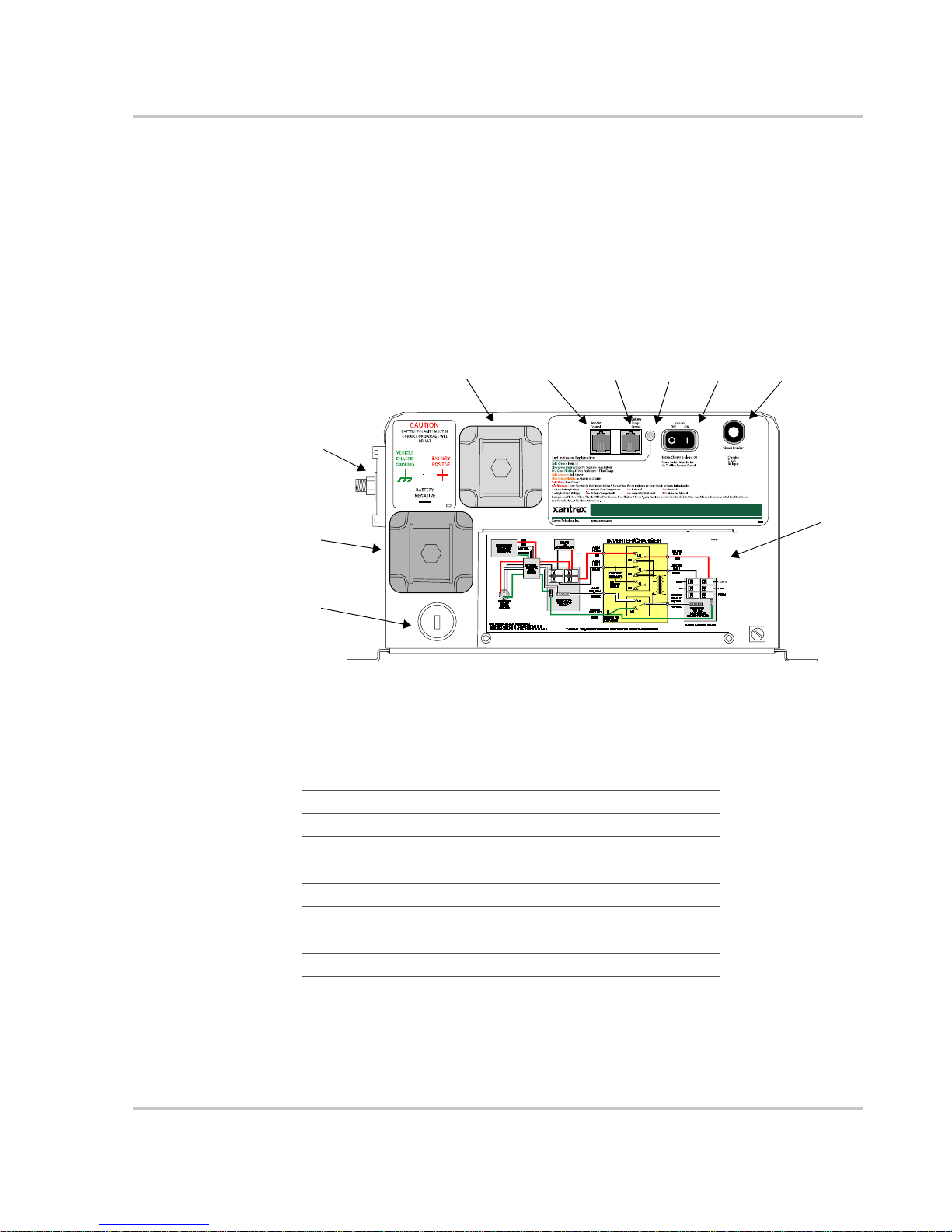
Front Panel Features
Before installing and operating the RV Series Inverter/Charger, review the front
panel features shown in Figure 1-1 and described in Table 1-2.
Features
3
2
1
Figure 1-1
Table 1-2
4
RV Series Inverter/Charger Front Panel Features
Front Panel Features
56 897
PN 270-0697-01- 01
30A
60A
Feature Description
1 AC wiring knockout
2 Negative DC terminal (black)
3 RV ground terminal (green)
4 Positive DC terminal (red)
5 Remote control jack
6 Battery Temp. Sensor jack
7 LED indicator light
8 Inverter
ON/OFF switch
9 Charger circuit breaker
10 AC wiring compartment cover (with wiring diagram)
30
10
975-0209-01-01 1–3
Page 16
Introduction
Accessories
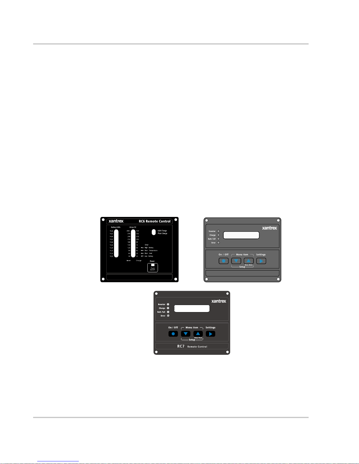
Remote Controls
Three remote control panels are available for the RV Series Inverter/Charger—
RC/GS, RC6 and RC7.
For inverter/charger on/off control and basic system monitoring, use the RC6
remote.
For complete inverter/charger configuration capability, use the RC7 or RC/GS
remotes. (The RV Series Inverter/Charger has an internal memory to retain its
configuration settings even with a loss of power.)
All RV Series inverter/chargers have a built-in shunt, which when paired with the
optional RC/GS remote control enables advanced battery monitoring and inverter/
charger control. To use the shunt, the inverter/charger must be wired correctly,
using the green RV ground terminal.
The RV Series Inverter/Charger also has the necessary built-in hardware to be
connected to your generator, enabling automatic generator starting when paired
with the optional RC/GS remote control.
Figure 1-2
RC6
RC7
Remote Control Panels
RC/GS
RC/GS Remote Control/Gen Starting
The RC6, RC7, and RC/GS use a telephone-style cord to connect to the RV Series
Inverter/Charger (models RV2012GS, RV2012GS-15/20B, RV2012GS-20B,
RV2512GS, and RV3012GS).
1–4 975-0209-01-01
Page 17
Use only Xantrex-recommended accessories. Remote cables are available in three
lengths:
Part number Cable Length
31-6257-00 25 feet
31-6262-00 50 feet
31-6275-00 70 feet
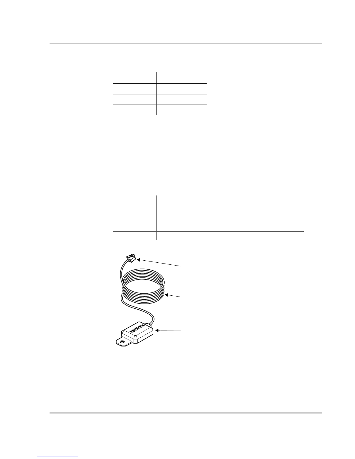
Battery Temperature Sensor
The battery temperature sensor (BTS) allows the inverter/charger to monitor the
battery temperature and adjust charging voltage according to the temperature. The
BTS can extend the life of a battery by preventing overcharging in warm
temperatures and undercharging in cold temperatures.
The BTS attaches to a battery terminal post or to the side of the battery using a
self-adhesive backing.
Table 1-3
Part number Details
130-0004-01-01 15 foot cord, surface mount only
130-0004-02-01 25 foot cord, surface mount only
130-0004-03-01 35-foot cord, surface mount only
808-0231 25-foot cord, surface or terminal mount (shown in Figure 1-3)
Accessories
Connector
25 foot (7.6 m) cord
Sensor
Figure 1-3
975-0209-01-01 1–5
Battery Temperature Sensor (808-0231)
Page 18

1–6
Page 19

2
Installation
Chapter 2 contains information and procedures to install the RV
Series Inverter/Charger.
The topics in this chapter are organized as follows:
• “Choosing a Location”
• “Wiring the Inverter/Charger”
• “Wiring to a Generator”
Page 20

Installation
Choosing a Location
Inverters are sophisticated electronic devices and should be treated accordingly.
When selecting the operating environment for the inverter, don’t think of it in the
same terms as other equipment that works with it, such as batteries, diesel
generators, motor generators, washing machines, and so on. It is a highly complex
microprocessor-controlled device, similar in nature to stereo equipment,
television sets, or computers. The use of conformal-coated circuit boards, plated
copper bus bars, powder-coated metal components, and stainless steel fasteners
improves tolerance to hostile environments. However, in a condensing
environment (one in which humidity and/or temperature change causes water to
form on components) all the ingredients for electrolysis are present: water,
electricity and metals. In a condensing environment the life expectancy of the
inverter is indeterminate and the warranty is voided.
CAUTION
Install the inverter in a dry, protected location away from sources of high temperature and
moisture. Exposure to salt water is particularly destructive and potentially hazardous.
The inverter/charger should only be installed in a location that meets the
following requirements:
Ventilated Do not operate the inverter/charger in a closed-in area or restrict
ventilation in any way. The inverter/charger requires air circulation
to maintain optimum operating temperature and provide best
performance. If the unit has inadequate ventilation, it may shut down
due to overheating.
The air vented through the openings should also have a path to
circulate away from the inverter/charger.
Dry Do not allow water or other fluids to drip or splash on the inverter.
Do not expose to rain, snow or water.
Cool Normal air temperature should be between 32 °F and 122 °F
(0 °C and 50 °C)—the cooler the better within this range.
Clearance Allow as much space around the inverter/charger as possible.
Xantrex recommends that other objects and surfaces be at least
3 inches (76 mm) away from the ventilation openings for best
performance.
Safe Locate the inverter/charger away from battery in a separate well
ventilated compartment. Do not install the inverter/charger in any
compartment containing flammable gases or liquids like gasoline.
Close to
battery
compartment
The length and size of your DC cables will affect performance. Use
the DC cables recommended in Table 2-2 on page 2–12. The unit
should not be installed in the battery compartment due to the
possible presence of explosive hydrogen gas from the batteries.
2–2 975-0209-01-01
Page 21

Choosing a Location
Protected
from battery
acid and gases
Never place the inverter/charger directly above the batteries—gases
from battery will corrode and damage the inverter/charger. If the
inverter/charger is installed in a compartment above the batteries,
make sure there is a solid, gas-impermeable wall dividing the two
compartments.
Never allow battery acid to drip on the inverter/charger or its wiring
when filling the batteries or reading their specific gravity.
Orientation To meet regulatory requirements, the inverter/charger must be
mounted in one of the approved mounting orientations:
• Desktop (as shown in Figure 2-1)
•Upside down
• Wall mounted with the AC terminal block facing up.
975-0209-01-01 2–3
Page 22

Installation
Wiring the Inverter/Charger
WARNING: Fire, shock, and energy hazards
Make sure all AC and DC wiring being connected to the RS is disconnected (physically or
by opening the breaker) from all electrical sources before handling. All wiring must be
done in accordance with local and national electrical wiring codes. Xantrex recommends
all wiring be done by a qualified installer or electrician.
For a successful installation, you need to plan the AC and DC wiring, as well as
the remote control and generator connections. These connections are described in
this section and illustrated in Figure 2-1.
AC components include:
• Sources of AC input
•AC wiring
• Over-current protection and disconnect devices
• AC distribution panels
DC components include:
• Sources of DC power (batteries, for example)
• DC cables
• DC over-current protection and disconnect devices
• DC load center
2–4 975-0209-01-01
Page 23

Battery Temperature
Sensor
DC +
DC Negative Grounding Bus
DC Fuse
House Battery
DC Load Center
Grounding (Bonding) Bus
DC Positive Bus
+
DC -
Isolator
Non-Inverter Loads
RV Series Inverter/Charger
PN 270-0697-01-01
AC In
AC Main Panel
Wiring the Inverter/Charger
RC/GS Remote
30
30A
60A
AC Out
Engine Negative Ter min a l
Engine Battery
/
RESET
RESET
TEST
TEST
TEST MONTHLY
GFCI
Sensing and control
Figure 2-1
Alternator
RV Electrical System Diagram
Important:
Figure 2-1 does not show all required grounding or over-current protection.
Generator
Transfer Switch
Inverter AC Panel
UtilityPower
AC Wiring
Overview The U.S. National Electrical Code (NEC) defines the standards for AC and DC
installation wiring in RV applications, but there are still many installation
variables. Most are determined by the level of automatic switching desired and the
amount of external AC power to be switched.
Installation should be done by a qualified electrician. Consult local code for the
proper wire sizes, connectors and conduit.
The AC and DC terminals are located on the same end of the chassis as the status
LED and power switch. A six station terminal block is provided to connect the AC
input and AC output. All terminals are labeled on the inverter. Consult your local
code for proper wire sizes, connectors, conduit, and so on. See Table 2-1 for
minimum recommended wire sizing. Code requires that an external disconnect
switch be used in the AC input wiring circuit. The AC breakers in a sub panel will
meet this requirement.
975-0209-01-01 2–5
Page 24

Installation
AC Input Wiring
Wiring
requirements
AC input to the inverter/charger can be supplied from a split-phase or dual-input
AC source such as the utility grid (power company), a generator, or the output of a
transfer switch. The inverter/charger can be operated from the following types of
120 volt 60 Hz AC sources:
• Split phase: This source type has two lines, one neutral, and one ground. The
two 120 VAC lines are 180 degrees out of phase with each other, so that the
two voltages total to 240 VAC. The voltage between each line and neutral is
still 120 VAC, and the voltage between the neutral and ground is
approximately zero.
• Dual input: This source type has two line inputs, one neutral, and one ground.
Unlike the split-phase type, the two lines are in phase (not out of phase), and
must come from the same source. The voltage between the two lines is zero.
The voltage between each line and the neutral is 120 VAC, and the voltage
between the neutral and ground is approximately zero.
• Single input: This source type uses only one line input, one neutral, and one
ground. Use line 1 (“AC Input Hot 1”) for AC input if only one line is
necessary. If only line 2 is used, the inverter/charger will not transfer power.
The type of wiring required varies according to the electrical codes or regulations
applicable to your installation. Wire size must be coordinated with the overcurrent protection provided ahead of the wire involved, in accordance with the
electrical codes or regulations applicable to your installation.
The AC circuit from the AC source to the inverter/charger input should be wired
using one four-conductor cable (two lines, one neutral and one ground).
The requirements for this configuration are as follows:
Requirement Details
Breaker Size and Type 30A two-pole
AC Wiring Temperature Rating 75 °C or higher
Color Coding Black: L1, Red: L2
White: N1
Bare or green: Gnd
Explanation of Wiring Size When the AC source is split-phase (two lines out
of phase), the currents from each line subtract in the neutral, and the neutral
current will be approximately zero if the loads are equal. For example, if Line 1 is
supplying 20A and Line 2 is supplying 15A, the current in the neutral will be 5A.
In single source input, only one line is used and therefore the neutral current will
never exceed the line current.
However, when the AC source is dual-input (two lines in phase), the currents from
each line add together in the neutral. For example, if line 1 and line 2 is each
supplying 30A, the current in the neutral will be 60A. Therefore, No. 6 AWG wire
is required.
2–6 975-0209-01-01
Page 25

Wiring the Inverter/Charger
General Precautions
AC disconnects No AC disconnects are provided as an integral part of this inverter. AC
disconnects must be provided as part of the system installation.
Over-current
protection
No over-current protection for the AC output wiring is provided as an integral part
of this inverter. Over-current protection of the AC output wiring must be provided
as part of the system installation.
AC neutral-ground
bonding instructions
This inverter/charger includes neutral ground switching for the AC electrical
system. The AC system must have the neutral isolated from the grounding system
throughout the load distribution circuits. AC generators must have the neutral
bonded to the grounding system when used with this inverter.
The inverter/charger provides a system that automatically connects the neutral
conductor of the inverter’s AC output circuit to safety ground (“bonding” it) while
the inverter/charger is inverting, and disconnects it (“unbonding” it) when the
inverter/charger is connected to external AC power. This system is designed to
conform to installation codes that require AC sources such as inverters and
generators to have their neutral conductors tied to ground at the source of power in
the same way that the neutral conductor from the utility is tied to ground. These
same codes specify that the neutral can only be connected to ground in one place
at any one time.
Installation with an External Transfer Relay (120/240 System)
WARNING: Shock hazard
Do not connect 240 Vac loads to the inverter/charger outputs. Doing so may result in
120 Vac on exposed parts of the appliance.
Figure 2-2
975-0209-01-01 2–7
Installation with an External Transfer Relay
Page 26

Installation
When the generator is running the main AC panel, leg 1 and leg 2 of the generator
are connected independently to the two halves of the main AC panel. When the
inverter is operating, both sides of the main AC panel are automatically connected
together. Only 120 Vac is available when the inverter is operating.
Use line 1 for AC input if only one line is necessary. If only line 2 is used, the
inverter/charger will not transfer power.
Tools and Materials Required
No terminals or lugs are required to connect the AC wiring.
Tools and materials required to make AC wiring connections:
❐ Wire strippers
❐ 1/2" (13 mm) open-end wrench or socket
❐ Phillips screwdriver #2
❐ Slotted screwdriver 1/4" (6 mm) blade.
❐ Four conductor wire, sized according to Table 2-1.
Table 2-1
Model
RV2012GS 10 AWG 10 AWG 6 AWG 6 AWG
RV2012GS-15/20B 12 AWG 14*/12** AWG 8 AWG 14*/12** AWG
RV2012GS-20B 12 AWG 12 AWG 8 AWG 12 AWG
RV2512GS 10 AWG 10 AWG 6 AWG 6 AWG
RV3012GS 10 AWG 10 AWG 6 AWG 6 AWG
Minimum Recommended AC Wire Size (Four-Conductor Cable)
Split Phase/Single Input Dual Input
Input Wiring Output Wiring Input Wiring Output Wiring
* for 15 A output breaker.
** for 20 A output breaker.
Torque all AC wiring connections to 20 inch-pounds.
2–8 975-0209-01-01
Page 27

Connecting the AC Wiring
AC connections are made on the terminal block located inside the front panel of
the inverter.
Wiring the Inverter/Charger
GFCI Requirements
Figure 2-3
RV Series AC Wiring terminal block
To connect AC wiring:
1. Disconnect the inverter from the battery.
2. Remove the AC wiring compartment cover.
3. Feed the wires through the Romex connectors on the right side of the
inverter’s case. Romex strain reliefs can be replaced with conduit fittings. See
Figure 2-2 on page 2–7.
4. Following the wiring guide located in the AC wiring compartment and
page 2–7, connect the hot (black) and neutral (white) wires to the terminal
block and tighten securely. The safety (green) wire is connected to the
external ground screw terminal.
5. Replace the AC wiring compartment cover.
A GFCI (ground fault circuit interrupter) is a device that deenergizes a circuit
when a current to ground exceeds a specified value that is less than that required
to open the circuit breaker. GFCIs are intended to protect people from electric
shocks and are usually required in wet or damp locations.
Installation in recreational vehicles requires GFCI protection of certain branch
circuits. Consult all applicable codes.
WARNING: Shock hazard
Not all makes and models of GFCIs work properly with all inverters. Use only GFCIs that
are listed as usable for your model of inverter in Xantrex Application Note “Using GFCI
Receptacles on Xantrex Inverters and Inverter/Chargers” available at www.xantrex.com
or by calling customer service; see page WA–1 for contact information.
975-0209-01-01 2–9
Page 28

Installation
DC Wiring
Safety Instructions
CAUTION: Equipment damage
THIS INVERTER IS NOT REVERSE POLARITY PROTECTED. If the positive
terminal of the battery is connected to the negative terminal of the inverter the probable
result is failure of the whole power stage. This type of failure is not covered under
warranty.
The inverter’s maximum peak current requirements are high. If battery cables are
too small and/or connections are loose, efficiency and maximum output power are
degraded. Small cables or loose connections can also cause dangerous
overheating of the wire and/or terminals.
Make the battery cables as large and as short as possible. Tape the battery cables
together. This reduces the inductance of the wire, resulting in a better waveform
and reduced stress on the inverter’s filter capacitors.
Refer to Table 2-2 on page 2–12 for recommended battery cable size. Crimped
and sealed copper ring terminal lugs with a 5/16" hole should be used to connect
the battery cables to the DC terminals of the inverter/charger. Soldered cable lugs
are also acceptable.
Code your battery cables with colored tape or heat-shrink tubing.
No DC disconnects are provided as an integral part of this inverter. DC
disconnects must be provided as part of the system installation.
Battery Requirements
Type Lead-acid deep-cycle battery or group of batteries. The batteries may be a
flooded, gel, or AGM type.
Volts 12 volts
More Information Go to www.xantrex.com/support for more information about batteries.
For detailed information about specific brands of batteries, you will need to
consult individual battery manufacturers.
DC Over-Current Protection
DC fusing In order to comply with the U.S. NEC, an approved form of battery over-current
protection is required. These installation parts are not supplied with the unit.
Standard-type DC fuses or circuit breakers may be obtained from your dealer,
electrical supply houses.
Xantrex offers a DC rated fuse and holder designed specifically for the RV Series
inverters. This fuse holder is available in a 200, 300, 350 and 400-amp sizes (refer
to Table 2-2 for proper fuse size). See the latest Xantrex RV Catalog or visit
www.xantrex.com for more information.
2–10 975-0209-01-01
Page 29

Wiring the Inverter/Charger
DC disconnects The DC circuit from the battery to the inverter/charger must be equipped with a
disconnect and over-current protection device. (Refer to your applicable
installation code.)
Type This device usually consists of a circuit breaker, a “fused-disconnect,” or a
separate fuse and DC disconnect. Do not confuse AC circuit breakers with DC
circuit breakers. They are not interchangeable.
Rating The rating of the fuse or breaker must be matched to the size of cables used, in
accordance with the applicable installation codes.
Location The breaker or fuse and disconnect should be located as close as possible to the
battery in the positive cable. The U.S. NEC (NFPA 70) specifies that the
protection can be no further than 18 inches from the battery. If using a fuse and
disconnect, the disconnect must be installed between the battery and the fuse.
Connection of Grounding and Battery Systems
This inverter/charger should be connected to a grounded, permanent wiring
system. For most installations, the negative battery conductor should be bonded to
the grounding system at one (and only one) point in the system. All installations
should comply with all national and local codes and ordinances.
CAUTION
• DO NOT connect the black battery negative (–) terminal to the vehicle chassis ground.
• DO NOT connect the DC load negative to the black battery negative (–). Connect only
to the green chassis ground terminal on the inverter or to the vehicle chassis. The
purpose of this terminal is to ensure that all DC load current into or out of the battery
bank will flow through the internal shunt of the inverter. The internal shunt is
connected between the black battery negative terminal and the green chassis ground
terminal of the inverter. Because all DC loads in a vehicle are generally connected to a
common chassis ground and not directly to the battery negative (in a negative-ground
system), all DC current in the system will at some point pass through the chassis and
then into the battery bank. If the inverter is in this loop the net current flow is easily
monitored. Thus, the remote control’s battery fuel gauge feature is possible. You may
connect the system without going through the chassis ground terminal, but the fuel
gauge feature will not work properly.
Figure 2-4 outlines proper connections for the RV Series inverter/chargers.
975-0209-01-01 2–11
Page 30

Installation
Vehicle chassis ground (green)
CAUTION
BATTERY POLARITY MUST BE
CORRECT OR DAMAGE WILL
RESULT
VEHICLE
CHASSIS
GROUND
BATTERY
NEGATIVE
BATTERY
POSITIVE
RV Series Inverter
30
30A
60A
Figure 2-4
Connect DC loads to Vehicle Chassis or optionally to the Inverter’s Vehicle Chassis
Ground Terminal (Green). The optional connection shown in Figure 2-4 is for
ungrounded DC load distribution panels. Do not connect DC loads to battery
negative (–).
Battery Cable Sizing
The bigger the battery cables, the better. Undersized cables result in additional
stress on the inverter, lower efficiency, reduced surge power, and lower peak
output voltage. Don’t use cables that are too small in diameter because they can
degrade the RV Series Inverter/Charger’s efficiency or generate enough heat to
become a fire hazard. The following table gives recommended cable sizes for
various cable run lengths and inverter voltages.
House Battery
Optional
connection
RV Series Grounding Diagram
DC Load Distribution Panel
Table 2-2
Model
RV2012GS 200 amps 250 A 00 0000
RV2512GS 250 amps 350 A 0000 0000
RV3012GS 300 amps 400 A 0000 0000
The U.S. NEC requires that the cables be protected by a fuse or breaker rated to
match the cables’ ampacity at 90 °C.
2–12 975-0209-01-01
Minimum Recommended Battery Cable Size (In Free Air)
Typical
Amps
Maximum
Fuse Size
Individual Cable length
Under 5 ft 5 to 10 ft
Page 31

WARNING: Fire hazard
Use only appropriately sized copper cable. Loose connections or improper connections
will overheat. Make sure the bolts supplied by Xantrex on the inverter/charger are
tightened to a torque of 15–16 ft-lbs (20.4–21.7 Nm). Torque all other connections to the
manufacturer’s specifications. Make sure the DC cable, washers, and bolt are assembled
in the order shown in Figure 2-5.
WARNING: Energy hazard
Connect and disconnect DC cabling only after opening the disconnect switches or
breakers at all AC and DC sources.
Battery Cable Connection
Observe battery polarity!
CAUTION: Reverse polarity damage
Before making the final DC connection or closing the DC breaker or disconnect, check
cable polarity at both the battery and the inverter/charger. Positive (+) must be connected
to positive (+). Negative (–) must be connected to negative (–).
Wiring the Inverter/Charger
To connect the DC cables:
1. Route the DC cables from the battery bank to the inverter/charger.
2. If using a DC fuse and disconnect switch, connect the portion of the positive
DC cable that is to run between these two components. Use a wrench to
tighten the bolt to the torque recommended by the fuseholder or breaker
manufacturer.
3. Open the DC disconnect switch or turn off the DC circuit breaker.
4. Place the ring terminal of the POSITIVE (+) cable over the bolt and directly
against the inverter’s battery terminal. Place a lock washer over the terminal.
Do not place the lock washer under the cable terminal. Figure 2-5.
Use a wrench to tighten the nut to a torque of 12 ft-lbs (16.3 Nm).
975-0209-01-01 2–13
Page 32

Installation
Figure 2-5
DC Cable Connection
5. Connect the connector at the other end of this cable to one of the terminals on
the fuse or breaker.
6. Use a wrench to tighten the bolt to the torque recommended by the fuseholder
or breaker manufacturer.
7. Connect one connector on the other section of the POSITIVE (+) cable to one
of the terminals on the disconnect switch (or to the other terminal on the
breaker). Use a wrench to tighten the bolt to the torque recommended by the
fuseholder or breaker manufacturer.
8. Connect the connector at the other end of this POSITIVE (+) cable to the
POSITIVE (+) DC terminal on the battery. Use a wrench to tighten the bolt to
the torque recommended by the battery manufacturer.
9. Connect one connector on the NEGATIVE (–) cable to the NEGATIVE (–)
terminal on the battery. Use a wrench to tighten the bolt to the torque
recommended by the battery manufacturer.
Before proceeding, check that the cable polarity is correct: POSITIVE (+) on
the inverter/charger is connected to the POSITIVE (+) on the battery, and
NEGATIVE (–) cable is connected to the NEGATIVE (–) terminal on the
battery.
Note: Connecting the battery cables to the inverter battery terminals will cause an arc,
usually accompanied by a “snap.”
10. Place the ring terminal of the NEGATIVE (–) cable over the bolt and directly
against the inverter’s battery terminal. Place a lock washer over the terminal.
Do not place the lock washer under the cable terminal. Figure 2-5.
Use a wrench to tighten the nut to a torque of 12 ft-lbs (16.3 Nm).
11. To protect the DC terminals, attach the supplied DC terminal covers, using the
screws provided.
2–14 975-0209-01-01
Page 33

Disconnecting
battery cables
Wiring the Inverter/Charger
CAUTION: Equipment damage
Never disconnect the battery cables while the inverter is delivering power or the battery
charger is operating. Disconnecting the battery cables could cause a rapid voltage increase
that could damage the charger or other DC loads. Keep in mind that the Inverter
switch on the inverter/charger does not turn off the charger section; it only turns off the
inverter.
To disconnect the batteries for service:
ON/OFF
1. Turn the Inverter
ON/OFF switch OFF.
2. Disconnect all AC inputs.
3. Disconnect the battery cables.
975-0209-01-01 2–15
Page 34

Installation
Connecting the Battery Temperature Sensor
Installing a battery temperature sensor (BTS) extends the life of a battery by
preventing overcharging in warm temperatures and undercharging in cold
temperatures. With a BTS monitoring the battery temperature, the voltage
delivered to the battery is adjusted according to the battery’s actual temperature.
The BTS has a self-adhesive backing and attaches to the side of the battery.
Mounting Options
You can mount the BTS in one of two ways, depending on which BTS model you
have:
• Option A: Mounting the sensor to the negative battery post allows the internal
battery temperature to be sensed and provides the most accurate results.
• Option B: Attaching the sensor to the side of the battery using the selfadhesive backing also provides good results in most situations.
Option A: Mounting to the Negative Battery Terminal
To mount the sensor on the negative battery terminal:
Figure 2-6
1. Select the battery to be monitored as follows:
• Identify the battery bank that is directly connected to the inverter/charger.
• Within that bank, if the batteries are in a row, select a battery in the middle
of the row. If the batteries are in a block, select a battery whose negative
battery terminal faces into the block.
2. Switch off all devices operating from the battery, and disconnect the battery
by opening the DC disconnect switch or the DC circuit breaker.
3. Wait sufficient time for any explosive battery gases to dissipate.
4. Remove the nut that connects existing wiring ring terminals to the battery
negative terminal stud.
2–16 975-0209-01-01
BTS Mounted on the Negative Battery Terminal
Page 35

Connecting the Battery T emperature Sensor
5. Move or reorient the existing wiring ring terminals on the battery negative
terminal stud, so there is a flat surface on which to seat the BTS mounting
plate. You may need to bend the ring terminal crimp and/or wires slightly
downward to allow the sensor to seat flush to the top surface of the upper ring
terminal.
6. Mount the sensor directly on top of the ring terminal, as shown in Figure 2-7,
and firmly tighten the terminal nut.
WARNING: Fire hazard
You must install the DC cable on the battery terminal, then install the sensor on top of the
DC cable. This sequence is required to provide the best connection to the battery and the
DC negative cable.
7. Check that the sensor and all wires are held firmly and cannot be moved.
8. Turn the battery switch on again (if you opened it in Step 2.)
9. Route the sensor cable to the inverter/charger and plug it into the Battery
Temp jack. Secure the cable along its length.
Option B: Mounting to the Side of the Battery Case
To mount the sensor on the battery case:
Figure 2-7
BTS Mounting
1. Select the battery to be monitored as follows:
• Identify the battery bank that is directly connected to the inverter/charger.
• Within that bank, if the batteries are in a row, select a battery in the middle
of the row.
2. Select a side suitable for attaching the sensor.
The surface where the sensor is to be mounted must be flat and free from
reinforcing ribs or other raised features. This surface must be in direct internal
contact with the battery electrolyte. Do not install the sensor near the top of
the battery or on the battery’s top surface.
975-0209-01-01 2–17
Page 36

Installation
3. Clean the selected area thoroughly to remove any oil or grease that could
prevent the sensor from adhering to the battery case. Allow the battery case to
dry thoroughly.
4. Peel the backing from the self-adhesive strip on the rear of the sensor. Press
the sensor firmly against the clean side of the battery to fix it in place, as
shown in Figure 2-7.
5. Route the sensor cable to the inverter/charger and plug it into the Battery
Temp. jack. Secure the cable along its length.
Wiring to a Generator
The RV Series Inverter/Charger is equipped with a sophisticated automatic
generator start (AGS) feature that can be accessed through the RC/GS Remote
Control. The RV Series Inverter/Charger AGS uses three dry contact relays to
operate the auto-start function of your AC generator. Proper installation and setup
of the generator is essential for correct operation of the inverter/charger. The RC/
GS contains the software code to work with various generators listed on its Select
Genset menu.
The RV Series Inverter/Charger AGS can be configured to start Onan
QuietDiesel, PowerTech and Generac-brand generators. For more information
about selecting a generator configuration, see the RV Series Remote Control
Owner’s Manual.
Generator Requirements
The maximum charge rate of the battery charger is dependent upon the peak AC
voltage available. Because this type of battery charger uses only the peak part of
the input sine wave, small variations in peak voltage result in large variations in
the amount of energy available to the charger. The charger’s rated output is based
on a utility voltage of 120 Vac
164 Vac
It takes a powerful AC generator set to maintain the full 164-volt peak while
delivering the current necessary to operate the charger at its maximum rate. As a
guideline, the rated output of the generator should be double the inverter output
(for example, a 5,000 W generator for a 2500 W inverter/charger). Smaller
generators will have the tops of their waveform clipped under such charger loads.
Running at these reduced peak voltages will not harm the charger, but it will limit
the maximum charge rate. Large auxiliary AC loads may make this problem
worse.
, which has a peak voltage of approximately
rms
.
p
2–18 975-0209-01-01
Page 37

Auto Gen Start connections
The connections between the inverter/charger and the generator are made on the terminal
strip. All these components are located inside the AC compartment of the inverter. See
Figure 2-8.
Wiring to a Generator
Figure 2-8
Terminal Name Relay Description
GEN STOP 2 Relay 1 normally open contact
GEN STOP 1 Relay 1 common contact
GEN STOP 3 Relay 1 normally closed contact
GEN START 2 Relay 2 normally open contact
GEN START 1 Relay 2 common contact
PREHEAT 1 Relay 3 normally open contact
PREHEAT 2 Relay 3 common contact
GEN RUN n/a Generator run signal input. This connection is required
THERMOSTAT + n/a Thermostat 5V–30V input.
THERMOSTAT – n/a Thermostat return (ground)
RV Series Auto Gen Start terminal block
for the inverter/charger to be able to detect when the
generator is running. For example, Power Tech supplies
a gray wire marked “12V power or +12V with engine
running.” This gray wire must connect to the GEN
RUN input.
975-0209-01-01 2–19
Page 38

Installation
Relay
timing
This diagram shows the activity of each internal relay during a generator start sequence.
Stop
Generac
configuration
Relay1: Glow/Stop
Relay2: Start (Cranking)
Relay3: Preheat (Glow)
Figure 2-9
Table 2-3
B+ Hold Time
Preheat Time
Preheat to Crank Delay
Crank Time
Crank Retry Time
Spindown Time
Stop Pulse Time
Post Stop Pulse Wait Time
Max Stop Tries
Starter Cooldown Time
Max Start Tries
Relay activity during a start sequence
Stop/Stop Sequence Timing
Preheat/
Stop
Preheat
Run
Start
Crank
Time
Onan
configuration
2 seconds 15 seconds 2 seconds
15 7 25
210
25 15 15
30 15 15
333
60 9 60
050
141
60 120 30
333
Power Tech
configuration
Wiring size You need #16 or #18 AWG wire to make generator connections. The wire gauge depends
on the distance between the RV Series Inverter/Charger and the generator.
0 to 30 ft. (9 m) Over 30 ft. (9 m)
18 AWG 16 AWG
Circuit
protection
Important:
Control relays must be protected with fuses rated at 5 amps or less.
2–20 975-0209-01-01
All circuits (except for ground connections) connecting to the Auto Gen
Page 39

Generator Wiring Diagrams
Onan
Wiring to a Generator
Power Tech
Figure 2-10
Figure 2-11
Onan QuietDiesel Wiring Diagram
Power Tech Wiring Diagram
975-0209-01-01 2–21
Page 40

Installation
Generac
GEN RUN
PREHEAT 2
PREHEAT 1
COM. GEN START 1
N.O. GEN START 2
N.C. GEN STOP 3
COM. GEN STOP 1
N.O. GEN STOP 2
Figure 2-12
Wiring to a Thermostat
With the RC/GS remote control, you can enable the RV Series Inverter/Charger AGS to
start the generator in response to 5 to 30 V output signal from a thermostat. Once
connected and enabled, the AGS will automatically start the generator when the air
conditioner or furnace needs to be run. You cannot program the thermostat itself with the
RC/GS. Thermostat connections are made on the terminal block (see Figure 2-8 on page
2–19).
5 A
5 A
5 A
Generac Wiring Diagram
GEN RUN SIGNAL (B+)
GENERATOR BATTERY POSITIVE
PREHEAT
GROUND
START
GENERATOR
WIRING HARNESS
Term inal name Connects to...
Thermostat + Thermostat input (5–30 V)
Thermostat – Thermostat return (ground)
For specific information about thermostat wiring and where AGS connections should be
made, please consult your thermostat documentation or contact the thermostat
manufacturer.
2–22 975-0209-01-01
Page 41

3
Operation
Chapter 3 contains information about operating the RV Series
Inverter/Charger.
Topics in this chapter include:
• “Remote Operation” on page 3–2
• “Stand-Alone Operation” on page 3–2
• “Search Mode” on page 3–2
• “Powering Loads” on page 3–3
• “Battery Charging” on page 3–7.
Page 42

Operation
Remote Operation
The RV Series Inverter/Charger is designed to operate stand alone or with a
remote panel. The supported remote panels are the RC/GS, RC7, and RC6. The
RC/GS enables advanced monitoring as well as configuration of the inverter/
charger and Automatic Generator Start feature. The RC7 offers inverter/charger
monitoring and configuration. RC6 is a basic status monitoring device with an on/
off button to enable or disable the inverter. Both the RC6 and RC7 connect to the
inverter/charger with a standard phone cord.
Stand-Alone Operation
When it is powered on, the RV Series Inverter/Charger performs a self-diagnostic
routine during which the indicator light on the front of the unit flickers red and
green. During this short boot-up interval, you will also hear a relay click. After
performing the self-diagnostic routine and the indicator light has stopped flashing,
the inverter/charger is ready for operation.
The inverter/charger features a front panel switch used to enable or disable the
inverter. When the switch is in the
either provide steady 120Vac or send out pulses if search sense mode is enabled.
See “Search Mode” for more information. When the switch is
charger begins charging if qualified AC power (power that is within a usable
voltage range—above 70 V) is connected to the inverter/charger input.
If qualified AC power (from shore power or a generator) is applied to the unit it
will transfer from inverter power to AC input power after approximately five
seconds and begin charging the batteries and powering any additional AC loads.
Because the charger is enabled by default, the unit is always ready to charge your
battery bank when qualified AC power is present.
ON position, the inverter is enabled and will
OFF, the inverter/
Search Mode
The RV Series Inverter/Charger features an adjustable search sense mode. This
mode minimizes power drain by reducing the inverter’s output to small test pulses
when there is no load connected. These pulses are used to detect the presence of a
load. When a load is detected the inverter’s output goes to full voltage. The
sensitivity of the detection threshold is adjustable.
The RV Series Inverter/Charger’s search sense threshold can only be set using the
Set Idle menu on the optional RC/GS or RC7 remote. However, once the mode is
set the remote may then be removed and the inverter will retain the settings.
Example With Set Idle set to detect a 40-watt load, a 50-watt load will bring the unit to full
output voltage. However, a 30-watt load will leave the inverter in its energysaving search sense mode. If the sensitivity is increased by changing Set Idle to
20, a 30-watt load will bring the inverter out of the search sense mode, while a 10watt load will not.
3–2 975-0209-01-01
Page 43

Powering Loads
When in the search sense mode, the green power LED will blink and the inverter
will make a ticking sound. At full output voltage, the green power LED will light
steadily and the inverter will make a steady humming sound. When the inverter is
used as an “uninterruptible” power supply the search sense mode function should
be defeated.
A neon-type nightlight can also be used as a good indicator to determine if the
inverter is in search sense mode. Simply plug the light into any AC outlet. When
the inverter is in the search sense mode the light will blink. If the inverter is
running a load, the light will be solid.
Exceptions Example A If Set Idle is set to detect a 40-watt load and a 30-watt incandescent
light is turned on, the inverter will detect the light. The light is a bigger load than
40 watts when its filaments are cold. When the light gets bright the filaments heat
up and the light becomes a 30-watt load. Since this is below the Set Idle setting of
40, the inverter will not detect it and the light will go out, beginning the process all
over again.
Example B If the Set Idle is set to detect a 30-watt load and a 40-watt
fluorescent light is turned on, the inverter will not detect the light. The light
presents a smaller load than 30 watts until the gas in the fluorescent tube ionizes.
Example C There are some appliances that draw power even though they are
turned off. TVs with instant-on circuits, microwave ovens with digital displays
and VCRs are examples. These loads present a dilemma. If the sensitivity is set
higher than the combination of these loads, then an auxiliary load must be used to
bring the inverter out of the search sense mode before the appliances can be turned
on. If the sensitivity is set lower than this combination of loads, the loads will be
left on and will put an additional drain on the batteries. (Three such 15-watt loads
would amount to an additional 90 amp hours per 24 hours in a 12 Vdc system.)
One solution is to turn these items off at the wall. Use an extension cord with a
rocker switch, a switch at the outlet, or the appropriate circuit breaker.
Powering Loads
Resistive Loads
These are the loads that the inverter finds the simplest and most efficient to drive.
Voltage and current are in phase, or, in this case, in step with one another.
Resistive loads usually generate heat in order to accomplish their tasks. Toasters,
coffee pots and incandescent lights are typical resistive loads. Larger resistive
loads—such as electric stoves and water heaters—are usually impractical to run
off an inverter. Even if the inverter could accommodate the load, the size of
battery bank required would be impractical.
975-0209-01-01 3–3
Page 44

Operation
Inductive Loads
Any device that has a coil of wire in it probably has an inductive load
characteristic. Most electronics have transformers (TVs, and stereos, for example)
and are therefore inductive. Typically, the most inductive loads are motors. The
most difficult load for the inverter to drive will be the largest motor you manage to
start. With inductive loads, the rise in voltage applied to the load is not
accompanied by a simultaneous rise in current. The current is delayed. The length
of the delay is a measure of inductance. The current makes up for its slow start by
continuing to flow after the inverter stops delivering a voltage signal. How the
inverter handles current that is delivered to it while it is essentially “turned off”
affects its efficiency and “friendliness” with inductive loads. The best place for
this out-of-phase current is in the load, and the RV Series Inverter/Charger’s
impulse phase correction circuitry routes it there.
Inductive loads, by their nature, require more current to operate than a resistive
load of the same wattage rating, regardless of whether power is being supplied by
an inverter, a generator or grid. An air conditioner is a common inductive load in
an RV.
Induction motors (motors without brushes) require two to six times their running
current on startup. The most demanding are those that start under load, such as
compressors and pumps. Of the capacitor start motors, typical in drill presses and
band saws, the largest you may expect to run is ½ to 1 hp. Universal motors are
generally easier to start. Since motor characteristics vary, only testing will
determine if a specific load can be started and how long it can be run.
If a motor fails to start within a few seconds, or it begins to lose power after
running for a time, it should be turned off. When the inverter attempts to start a
load that is greater than it can handle, it will turn itself off after about 10 seconds.
Low Battery Dropout
The inverter will turn off to protect itself if your battery bank cannot deliver the
necessary amperage to drive a particular load without falling below the low
voltage protection point (10.5 V) for three seconds. With the inverter off, the
battery voltage will rise and then it will resume operation.
Problem Loads
Xantrex inverters can drive nearly every type of load. However, there are special
situations in which inverter power may behave differently than utility power.
Very small loads If the power consumed by a device is less than the threshold
of the search mode circuitry, it will not run. This can usually be solved by
plugging in an additional load such as a 100-watt light bulb.
Fluorescent lights and power supplies Some devices when scanned by the
load sensor cannot be detected. Small fluorescent lights are the most common
example. (Try altering the plug polarity by turning the plug over.) Some
computers and sophisticated electronics have power supplies that do not present a
3–4 975-0209-01-01
Page 45

Powering Loads
load until line voltage is available. When this occurs, each unit waits for the other
to begin. To drive these loads either a small companion load must be used to bring
the inverter out of its search mode, or the inverter may be programmed to remain
at full output voltage. See “Search Mode” on page 3–2.
Microwave ovens Microwave ovens are sensitive to peak output voltage. The
higher the voltage, the faster they cook. Inverter peak output voltage is dependent
on battery voltage and load size. The high power demanded by a full-sized
microwave will drop the peak voltage several volts due to internal losses.
Therefore, the time needed to cook food will be increased if battery voltage is low.
Printers Most inkjet printers work well in inverter applications. Laser printers,
however, require high current for their fusing circuit and are not recommended for
use with an inverter.
Clocks The inverter’s crystal-controlled oscillator keeps the frequency accurate
to within a few seconds a day. However, external loads in the system may alter the
inverter’s output waveform, causing clocks to run at different speeds. This may
result in periods during which clocks keep time and then mysteriously do not.
Most clocks do not draw enough power to trigger the load-sensing circuit. In order
to operate without other loads present, the load sensing will have to be defeated.
(See “Search Mode” on page 3–2.) Clock accuracy is also affected by the
accuracy of the generator.
Dimmer Switches Most dimmer switches lose their ability to dim the lights and
operate either fully on or off.
Rechargeable Devices When first using a rechargeable device, monitor its
temperature for 10 minutes to ensure that it does not become abnormally hot.
Excessive heat will indicate that it is incompatible with the inverter.
Electronics AM radios will pick up noise, especially on the lower half of their
band. Inexpensive tape recorders are likely to pick up a buzz. Large loads should
not be started while a computer is operating off the inverter. If a load is large
enough to require “soft starting” it will “crash” the computer, causing it to reboot.
975-0209-01-01 3–5
Page 46

Operation
Typical Battery Draw of Common Appliances
Amp Hours Consumed Over Time
Appliance Watts
Single PL light 10 .1 .3 .7 1.3 2.7 5.3
Computer 10012481734
Color TV 13" 200 2 4 8 17 34 67
Blender 400 3 8 17 34 67 133
Skil Saw 800 6 173467133266
Toaster 1000 8 23 46 93 185 370
Microwave 1200102857114227455
Hot Plate 1800154488176353706
5 min 10 min 30 min 1 hr 2 hr 4 hr
If the current draw at 120 Vac is known, then the battery amperage at 12 Vdc will
be 10 times the AC amperage divided by the efficiency (90% in this table).
Motors are normally marked with their running rather than their starting current.
Starting current can be five times running current.
Refrigerators and ice makers typically run about one-third of the time. Therefore,
their average battery current draw is one-third of what their amp rating would
indicate.
3–6 975-0209-01-01
Page 47

Battery Charging
The RV Series Inverter/Charger battery charger uses three-stage charging to
provide rapid and complete charge cycles without undue battery gassing. The
three stages are bulk, absorption, and float.
Stage One: Bulk Charge (Constant Current)
This stage begins when qualified AC is applied to the AC input of the inverter.
The bulk charging stage charges the batteries at a constant current. The level of
charge for this phase is set using the Max Charge Rate menu on the RC/GS or
RC7. The constant current phase ends when the batteries reach the bulk charge
voltage. During this stage the Charger LED glows orange.
Stage Two: Absorption (Constant Voltage)
Absorption begins when the bulk voltage setting has been reached. At this point
the charge current begins to taper off at whatever rate is required to hold the
voltage constant. During this stage the Charger LED blinks orange. The
absorption phase ends in one of two ways.
Battery Charging
1. Normally, as the charge cycle progresses, the current required to hold the
battery voltage constant gradually reduces. When this current equals the
internal return amps setting, the voltage is allowed to fall to the float voltage
setting—stage three. This is a variable stage that can be affected by DC load
and battery condition.
2. After a time interval determined by the Battery Capacity setting. With a
125 Ah battery bank, the charger will leave the absorption phase after 1 hour.
With a 1000 Ah battery bank, the charger will leave the absorption phase after
3 hours.
Stage Three: Float Voltage
Float voltage maintains the batteries at a voltage that will hold full charge but not
gas the batteries. The charger remains in the float stage until the AC input is
removed. During this stage the Charger LED flashes green four times per second.
Note: When DC loads are placed on the battery, the charger will deliver currents up to
the Maximum Charge Rate setting while maintaining the float voltage.
Temperature-Compensated Charging
The RV Series Inverter/Charger is designed to provide temperature compensated
battery charging for optimal battery charging when used with a battery
temperature sensor (BTS). The BTS attaches to the side of your battery and
continuously measures the temperature of the battery and adjusts the charger
output for a more accurate, temperature-compensated charge.
975-0209-01-01 3–7
Page 48

Operation
When batteries are cold, their chemical reaction is sluggish, and they do not
absorb charge as easily. Therefore, a charge level optimized for room temperature
will not charge the batteries sufficiently if they are cold. The charger must
compensate by increasing its voltage to achieve the compensated equivalent of a
room temperature charge.
If the batteries are hot, the chemical reaction is hyperactive and they absorb
energy too easily. Therefore, a standard room-temperature charge would tend to
overcharge a hot battery. Therefore, the main charger compensates by reducing its
voltage.
With a BTS, the charger automatically, and continuously, makes adjustments to
the charger output voltage to properly charge your batteries. The actual charge
compensation slope based on cell voltage is –2.17mV per degree F per cell.
If a BTS is not present, the charger uses voltage settings as shown in Table B-1 on
page B–7.
Dead Battery Charging
Unlike many chargers, the RV Series Inverter/Charger can recharge batteries even
if the battery voltage is very low—as low as 5.5 V for a 12 V battery. Of course, it
is not recommended to ever discharge deep-cycle batteries this much.
Battery Equalization
To improve the life and performance of non-sealed, flooded lead-acid batteries,
the inverter/charger’s multi-stage charging cycle includes a manual equalize mode
that can be used if recommended by the battery manufacturer.
The equalization charge is manually initiated because it is not required each time
the battery is recharged. Equalization is a deliberate overcharge designed to
reduce sulfation and stratification in the battery. This helps the battery to reach
and maintain peak capacity by equalizing the chemistry in the individual battery
cells.
Follow the battery manufacturer’s recommendations for equalizing your batteries.
As a guide, a heavily used flooded battery may need to be equalized once a month,
and a battery in light service may only need to be equalized every two to four
months.
WARNING: Explosive gases
Equalization generates explosive gases. Ensure adequate ventilation.
3–8 975-0209-01-01
Page 49

Battery Charging
CAUTION: Batteries may be damaged
Sealed lead-acid batteries and gel batteries must NEVER be equalized, or premature
battery failure will result. Equalize mode is disabled if you have selected “GEL Cell” as
the battery type.
Only flooded lead-acid batteries should be equalized. As a general rule, do not equalize a
battery unless there are provisions to add water to it and the manufacturer recommends
equalization.
CAUTION: Batteries may be damaged
If carried out too frequently or done improperly, equalization can damage your batteries.
Never equalize a battery more than necessary. Always check electrolyte level before AND
after equalization. Fill with distilled water per the battery manufacturer’s
recommendation.
CAUTION: Risk of damage to DC load equipment
Equalization voltage may be as high as 15.5 volts DC. Disconnect sensitive loads from the
battery before equalizing.
To enter equalize charge mode using the RC7 or RC/GS:
◆ When the inverter/charger is charging, press and hold the Settings button
(right arrow) until the screen clears and “Equalizing” appears (approximately
6 seconds).
The Charge LED will increase its flashing rate to approximately 8 flashes per
second (flickering). The Equalize charge will continue for 3 hours and then
automatically change back to Float.
To cancel Equalize mode:
◆ Press and hold the Settings button for approximately 6 seconds.
If Equalization is cancelled, the screen will indicate the System Status as
Absorption chg for approximately 30 seconds before returning to Float charging.
975-0209-01-01 3–9
Page 50

Operation
LED Indicator
Charger activity The RV Series Inverter/Charger has a three-color LED that indicates the activity
of the battery charger. The optional RC/GS or RC7 remote allows custom control
over the charger section of the inverter, including battery type.
Table 3-1
LED color LED behavior Charger Activity
Orange Solid Bulk charging
Orange Flashing Absorption charge
Green Fast flashing (four times per second) Float charge
Orange Flashing Equalization charge
LED color and Charger Activity
Inverter activity In addition to indicating charger activity, the three-color LED reports on inverter
activity and error conditions.
Table 3-2
LED color LED behavior Inverter Activity
Green Solid Inverting
Green Slow flashing (once per second) Search Mode
Red Solid Over current condition
Red Flashing Error condition
LED color and Charger Activity
3–10 975-0209-01-01
Page 51

Error Conditions
LED Indicator
When an error condition occurs, the LED will flash red, followed by a five-second
rest period. You can identify error conditions by counting the number of times the
LED flashes before turning off for five seconds. The following table lists LED
flashing patterns and their associated error conditions.
Table 3-3
Number
of Flashes Error Condition Cause
a.Because voltages vary according to the load on the inverter , all voltages in this
table are ±0.3 V.
LED activity and Error Conditions
1 Low battery voltage
2 High battery voltage Battery voltage has risen to 15.7 V. The RV Series
3 Inverter over-
temperature
4 Battery charger fault Charger not charging correctly.
6 Generator start fault The RV Series has tried to start the generator three
8 Internal sensor error Analog-digital converter is faulty.
9 Internal memory
error
Battery voltage has fallen to 10.5 V
Series stops inverting. This error clears when the
voltage rises to 11.6 V.
stops inverting. This error clears when the voltage
rises to 15.4 V.
The FET and transformer temperature has risen to
194°F (90°C). The RV Series stops inverting or
charging. This error clears when the temperature
falls below 194°F (90°C).
times without detecting a B+ signal.
Internal processor is faulty.
a
. The RV
975-0209-01-01 3–11
Page 52

3–12
Page 53

4
Troubleshooting
Chapter 4 contains information and procedures to troubleshoot the RV
Series Inverter/Charger.
Page 54

Troubleshooting
Troubleshooting Guide
Symptoms Problem Remedy
No power output and
no warning LEDs
No power output and
LED indicator is
flashing green
No power output and
Red error LED is on
or flashing
Inverter turns loads
on and off
Inverter clicks every
20 seconds
Charger is
inoperative
Battery voltage at the inverter’s
terminals is too low or not present.
Load is too small for search sense mode
circuit to detect.
• Battery voltage is too low or too high
• Overcurrent condition
• Over-temperature condition
• Low battery
• Loose or corroded battery
connections
• Loose AC output connections
• Search sense threshold is too high
The output of the inverter is wired back
to its own input.
• The AC input voltage does not match
the inverter spec.
• The RV Series charger circuit breaker
has blown.
Check the battery voltage, fuses or switches and
cable connections.
Reduce search threshold setting or defeat search
mode (“Set Idle” on the remote).
• Check the battery voltage at the inverter’s
terminals
• Remove loads from the inverter and restart
• Remove loads and let inverter cool down
before restarting
• Check condition of batteries and recharge if
possible
• Check and clean all connections
• Check all AC output connections
• Disable search sense mode or set search
sense mode (“Set Idle”) lower.
Check for proper AC input and output wiring
• Check AC input for proper voltage and
frequency of your model.
• Reset breaker, check installation.
Batteries apparently
not being charged
correctly
Overload LED “ON”
while charging
Low charge rate • Low peak AC input voltage (164 V
Low AC output
voltage
Low surge power Weak batteries, battery cables are too
AC Lights flicker
while charging
4–2 975-0209-01-01
• Charge controls are improperly set.
• The BTS has adjusted the charge
voltage.
Charger circuit may be damaged. Have inverter serviced.
peak required for full charger output).
• AC current output of generator is too
small to handle the load.
Measuring with the wrong type of
voltmeter (displays 80–100 VAC).
small or too long.
Generator is unstable—charger is losing
synchronization
• Ensure Battery Capacity, Battery Type, and
Max Charge Rate settings are correct.
• No remedy if the BTS is installed correctly
and operating.
• Use a larger generator, speed up the
generator, check AC input wiring size,
adjust charge rate, battery cables are too
small or too long.
• Reduce charge amps setting or reduce passthrough loads.
Voltmeter must be a true RMS reading meter
(most are not).
Refer to cable and battery recommendations in
owner’s manual.
Turn battery charger rate (“Max Charge Rate”)
down until problem is gone.
Page 55

A
Specifications
Appendix A contains contains the electrical, environmental, and
physical specifications for the RV Series Inverter/Charger.
All specifications are subject to change without notice.
Page 56

Specifications
Electrical Specifications
RV2012GS RV2512GS RV3012GS
Continuous Power @ 25°C 2000 watts 2500 watts 3000 watts
Max AC Current 16.6 amps 20.8 amps 25 amps
Efficiency 94% Peak
Input Current: Search Mode 0.055 amps 0.070 amps 0.080 amps
Input Current: Full Voltage 0.550 amps 0.600 amps 0.650 amps
Input Current: At Rated Power 200 amps 250 amps 300 amps
Input Current: Short Circuit 600 amps 800 amps 900 amps
Minimum input AC Voltage 40 Vac
Nominal Input Voltage 12 Vdc
Input Voltage Range 10.5–15.5 Vdc
Voltage Regulation—Maximum ±5%
Voltage Regulation—Typical ±2.5%
Output Waveform Modified sine
Power Factor allowed -1 to +1
Frequency Regulation 60Hz ± .04%
Standard Output Voltage 120 Vac
Adjustable Search Sense Range 20 to 50 watts
Forced Air Cooling Variable Speed
Automatic Transfer Relay 50 amps at 120/240 Vac split phase or 30 amps at 120 Vac single/dual input
(field configurable)
Adjustable Charge Rate 10–100 amps 10–120 amps 10–140 amps
Number of Charging Profiles 3 (GEL Cell, Flooded lead acid, AGM)
Three-Stage Charging Yes
Environmental Specifications
Operating ambient temperature 0 ° – 50 °C (32 ° – 122 °F)
Non-operating temperature -55 ° – 75 °C (-67 ° – 167 °F)
A–2 975-0209-01-01
Page 57

Physical Specifications
Physical Specifications
RV2012GS RV2512GS RV3012GS
Weight 45 lb (20.5 kg) 50 lb (22.7 kg) 60 lb (27.2 kg)
Dimensions (L × W × H) 15.5 × 13.2 × 7.25" (39.4 × 33.5 × 18.4 cm)
Mounting Desktop, upside down, wall mount with AC terminal block facing up
Accessories
Battery Temperature Sensor Optional
Remote Control Optional RC6, RC7, RC/GS
Remote Control Cables 31-6257-00 (25 feet), 31-6262-00 (50 feet),
31-6275-00 (70 feet)
Regulatory Approvals
UL Listed to UL458
975-0209-01-01 A–3
Page 58

A–4
Page 59

Warranty and Return Information
Warranty
What does this warranty cover? This Limited Warranty is provided by Xantrex Technology Inc. ("Xantrex")
and covers defects in workmanship and materials in your RV Series Inverter/Charger. This warranty period lasts for
36 months from the date of purchase at the point of sale to you, the original end user customer. You require proof of
purchase to make warranty claims.
This Limited Warranty is transferable to subsequent owners but only for the unexpired portion of the Warranty
Period. Subsequent owners also require proof of purchase.
What will Xantrex do? Xantrex will, at its option, repair or replace the defective product free of charge,
provided that you notify Xantrex of the product defect within the Warranty Period, and provided that Xantrex through
inspection establishes the existence of such a defect and that it is covered by this Limited Warranty.
Xantrex will, at its option, use new and/or reconditioned parts in performing warranty repair and building
replacement products. Xantrex reserves the right to use parts or products of original or improved design in the repair
or replacement. If Xantrex repairs or replaces a product, its warranty continues for the remaining portion of the
original Warranty Period or 90 days from the date of the return shipment to the customer, whichever is greater. All
replaced products and all parts removed from repaired products become the property of Xantrex.
Xantrex covers both parts and labor necessary to repair the product, and return shipment to the customer via a
Xantrex-selected non-expedited surface freight within the contiguous United States and Canada. Alaska and Hawaii
are excluded. Contact Xantrex Customer Service for details on freight policy for return shipments outside of the
contiguous United States and Canada.
How do you get service? If your product requires troubleshooting or warranty service, contact your merchant. If
you are unable to contact your merchant, or the merchant is unable to provide service, contact Xantrex directly at:
Telephone: 1 800 670 0707 (toll free North America)
1 360 925 5097 (direct)
Fax: 1 360 925 5143 (direct)
Email: customerservice@xantrex.com
Direct returns may be performed according to the Xantrex Return Material Authorization Policy described in your
product manual. For some products, Xantrex maintains a network of regional Authorized Service Centers. Call
Xantrex or check our website to see if your product can be repaired at one of these facilities.
What proof of purchase is required? In any warranty claim, dated proof of purchase must accompany the
product and the product must not have been disassembled or modified without prior written authorization by Xantrex.
Proof of purchase may be in any one of the following forms:
• The dated purchase receipt from the original purchase of the product at point of sale to the end user, or
• The dated dealer invoice or purchase receipt showing original equipment manufacturer (OEM) status, or
• The dated invoice or purchase receipt showing the product exchanged under warranty
975-0209-01-01 WA–1
Page 60

Warranty and Return
What does this warranty not cover? This Limited Warranty does not cover normal wear and tear of the
product or costs related to the removal, installation, or troubleshooting of the customer's electrical systems. This
warranty does not apply to and Xantrex will not be responsible for any defect in or damage to:
a) the product if it has been misused, neglected, improperly installed, physically damaged or altered, either inter-
nally or externally, or damaged from improper use or use in an unsuitable environment;
b) the product if it has been subjected to fire, water, generalized corrosion, biological infestations, or input voltage
that creates operating conditions beyond the maximum or minimum limits listed in the Xantrex product specifications including high input voltage from generators and lightning strikes;
c) the product if repairs have been done to it other than by Xantrex or its authorized service centers (hereafter
"ASCs");
d) the product if it is used as a component part of a product expressly warranted by another manufacturer;
e) the product if its original identification (trade-mark, serial number) markings have been defaced, altered, or
removed.
Disclaimer
Product
THIS LIMITED WARRANTY IS THE SOLE AND EXCLUSIVE WARRANTY PROVIDED BY XANTREX IN CONNECTION WITH YOUR
XANTREX PRODUCT AND IS, WHERE PERMITTED BY LAW, IN LIEU OF ALL OTHER WARRANTIES, CONDITIONS,
GUARANTEES, REPRESENTATIONS, OBLIGATIONS AND LIABILITIES, EXPRESS OR IMPLIED, STATUTORY OR OTHERWISE IN
CONNECTION WITH THE PRODUCT, HOWEVER ARISING (WHETHER BY CONTRACT, TORT, NEGLIGENCE, PRINCIPLES OF
MANUFACTURER'S LIABILITY, OPERATION OF LAW, CONDUCT, STATEMENT OR OTHERWISE), INCLUDING WITHOUT
RESTRICTION ANY IMPLIED WARRANTY OR CONDITION OF QUALITY, MERCHANTABILITY OR FITNESS FOR A PARTICULAR
PURPOSE. ANY IMPLIED WARRANTY OF MERCHANTABILITY OR FITNESS FOR A PARTICULAR PURPOSE TO THE EXTENT
REQUIRED UNDER APPLICABLE LAW TO APPLY TO THE PRODUCT SHALL BE LIMITED IN DURATION TO THE PERIOD
STIPULATED UNDER THIS LIMITED WARRANTY.
IN NO EVENT WILL XANTREX BE LIABLE FOR ANY SPECIAL, INDIRECT, INCIDENTAL OR CONSEQUENTIAL DAMAGES,
LOSSES, COSTS OR EXPENSES HOWEVER ARISING WHETHER IN CONTRACT OR TORT INCLUDING WITHOUT RESTRICTION
ANY ECONOMIC LOSSES OF ANY KIND, ANY LOSS OR DAMAGE TO PROPERTY, ANY PERSONAL INJURY, ANY DAMAGE OR
INJURY ARISING FROM OR AS A RESULT OF MISUSE OR ABUSE, OR THE INCORRECT INSTALLATION, INTEGRATION OR
OPERATION OF THE PRODUCT.
Exclusions
If this product is a consumer product, federal law does not allow an exclusion of implied warranties. To the extent you
are entitled to implied warranties under federal law, to the extent permitted by applicable law they are limited to the
duration of this Limited Warranty. Some states and provinces do not allow limitations or exclusions on implied
warranties or on the duration of an implied warranty or on the limitation or exclusion of incidental or consequential
damages, so the above limitation(s) or exclusion(s) may not apply to you. This Limited Warranty gives you specific
legal rights. You may have other rights which may vary from state to state or province to province.
Warning: Limitations On Use
Please refer to your product manual for limitations on uses of the product.
SPECIFICALLY, PLEASE NOTE THAT THE RV S ERIES INVERTER/CHARGER SHOULD NOT BE USED IN CONNECTION WITH
LIFE SUPPORT SYSTEMS OR OTHER MEDICAL EQUIPMENT OR DEVICES. WITHOUT LIMITING THE GENERALITY OF THE
FOREGOING, XANTREX MAKES NO REPRESENTATIONS OR WARRANTIES REGARDING THE USE OF THE XANTREX
S
ERIES INVERTER/CHARGER IN CONNECTION WITH LIFE SUPPORT SYSTEMS OR OTHER MEDICAL EQUIPMENT OR
DEVICES.
Please note that the RV Series Inverter/Charger is not intended for use as an uninterruptible power supply and
Xantrex makes no warranty or representation in connection with any use of the product for such purposes.
WA–2 975-0209-01-01
RV
Page 61

Warranty and Return
Return Material Authorization Policy
Before returning a product directly to Xantrex you must obtain a Return Material Authorization (RMA) number and
the correct factory "Ship To" address. Products must also be shipped prepaid. Product shipments will be refused and
returned at your expense if they are unauthorized, returned without an RMA number clearly marked on the outside of
the shipping box, if they are shipped collect, or if they are shipped to the wrong location.
When you contact Xantrex to obtain service, please have your instruction manual ready for reference and be prepared
to supply:
• The serial number of your product
• Information about the installation and use of the unit
• Information about the failure and/or reason for the return
• A copy of your dated proof of purchase
Record these details on page WA–4.
Return Procedure
1. Package the unit safely, preferably using the original box and packing materials. Please ensure that your product
is shipped fully insured in the original packaging or equivalent. This warranty will not apply where the product is
damaged due to improper packaging.
2. Include the following:
• The RMA number supplied by Xantrex Technology Inc. clearly marked on the outside of the box.
• A return address where the unit can be shipped. Post office boxes are not acceptable.
• A contact telephone number where you can be reached during work hours.
• A brief description of the problem.
3. Ship the unit prepaid to the address provided by your Xantrex customer service representative.
If you are returning a product from outside of the USA or Canada In addition to the above, you MUST
include return freight funds and are fully responsible for all documents, duties, tariffs, and deposits.
If you are returning a product to a Xantrex Authorized Service Center (ASC) A Xantrex return
material authorization (RMA) number is not required. However, you must contact the ASC prior to returning the
product or presenting the unit to verify any return procedures that may apply to that particular facility.
Out of Warranty Service
If the warranty period for your RV Series Inverter/Charger has expired, if the unit was damaged by misuse or
incorrect installation, if other conditions of the warranty have not been met, or if no dated proof of purchase is
available, your unit may be serviced or replaced for a flat fee.
To return your RV Series Inverter/Charger for out of warranty service, contact Xantrex Customer Service for a Return
Material Authorization (RMA) number and follow the other steps outlined in “Return Procedure” on page WA–3.
Payment options such as credit card or money order will be explained by the Customer Service Representative. In
cases where the minimum flat fee does not apply, as with incomplete units or units with excessive damage, an
additional fee will be charged. If applicable, you will be contacted by Customer Service once your unit has been
received.
975-0209-01-01 WA–3
Page 62

Warranty and Return
Information About Your System
As soon as you open your RV Series Inverter/Charger package, record the following information and be sure to keep
your proof of purchase.
❐ Serial Number
❐ Purchased From
❐ Purchase Date
If you need to contact Customer Service, please record the following details before calling. This information will help
our representatives give you better service.
❐ Type of installation (e.g. RV, truck)
❐ Length of time inverter has been installed
❐ Battery/battery bank size
❐ Battery type (e.g. flooded, sealed gel cell, AGM)
❐ DC wiring size and length
❐ Alarm sounding?
❐ Description of indicators on front panel
❐ Appliances operating when problem occurred
❐ Description of problem
_________________________________
_________________________________
_________________________________
__________________________________
__________________________________
__________________________________
__________________________________
__________________________________
__________________________________
__________________________________
__________________________________
__________________________________
______________________________________________________________________________________
______________________________________________________________________________________
WA–4 975-0209-01-01
Page 63

Page 64

Xantrex Technology Inc.
1 800 670 0707 Tel toll free NA
1 360 925 5097 Tel direct
1 360 925 5143 Fax direct
customerservice@xantrex.com
www.xantrex.com
975-0209-01-01
Printed in China
 Loading...