

Page 1

RS3000 Sine Wave Inverter/Charger
RS3000
Operation Guide
Page 2

Page 3

RS3000 Sine Wave Inverter/Charger
Operation Guide
Page 4

About Xantrex
Xantrex Technology Inc. is a world-leading supplier of advanced power electronics and controls with products from
50 watt mobile units to one MW utility-scale systems for wind, solar, batteries, fuel cells, microturbines, and backup
power applications in both grid-connected and stand-alone systems. Xantrex products inclu de inverters, batt ery
chargers, programmable power supplies, and variable speed drives that convert, supply, control, clean, and distribute
electrical power.
Trademarks
RS3000 Sine Wave Inverter/Charger is a trademark of Xantrex International. Xantrex and Xanbus are registered
trademarks of Xantrex International.
Other trademarks, registered trademarks, and product names are the property of their respective owners and are used
herein for identification purposes only.
Notice of Copyright
RS3000 Sine W a ve Inverter/Charger Operation Guide © April 2007 Xantrex International. All rights reserved.
Disclaimer
UNLESS SPECIFICALLY AGREED TO IN WRITING, XANTREX TECHNOLOGY INC. (“XANTREX”)
(a) MAKES NO WARRANTY AS TO THE ACCURACY, SUFFICIENCY OR SUITABILITY OF ANY
TECHNICAL OR OTHER INFORMATION PROVIDED IN ITS MANUALS OR OTHER DOCUMENTATION.
(b) ASSUMES NO RESPONSIBILITY OR LIABILITY FOR LOSS OR DAMAGE, WHETHER DIRECT,
INDIRECT, CONSEQUENTIAL OR INCIDENTAL, WHICH MIGHT ARISE OUT OF THE USE OF SUCH
INFORMATION. THE USE OF ANY SUCH INFORMATION WILL BE ENTIRELY AT THE USER’S RISK.
Date and Revision
April 2007 Rev D
Part Number
975-0170-01-01
Contact Information
Telephone: 1 800 670 0707 (toll free North America)
1 360 925 5097 (direct)
Fax: 1 800 994 7828 (toll free North America)
1 360 925 5143 (direct)
Email: customerservice@xantrex.com
Web: www.xantrex.com
Page 5

About This Guide
Purpose
The RS3000 Sine Wave Inverter/Charger Operation Guide provides
explanations and procedures for operating, configuring, and
troubleshooting the RS3000 Sine Wave Inverter/Charger (RS3000).
Scope
The guide provides safety guidelines and information about operating,
configuring, and troubleshooting the unit. It does not include information
for installing the inverter/charger. Refer to the RS3000 Sine Wave
Inverter/Charger Installation Guide.
The guide also provides general guidelines on batteries; it does not
provide details about particular brands of batteries. You need to consult
individual battery manufacturers for this information.
Audience
The guide is intended for users who need to configure and operate the
RS3000 Sine Wave Inverter/Charger.
Organization
This guide is organized into four chapters and three appendixes.
Chapter 1, “Introduction”, outlines the main performance and safety
features of the RS3000 Sine Wave Inverter/Charger. Reading this chapter
will give you a clear understanding of the inverter/charger’s capabilities.
Chapter 2, “Operation”, provides information about operating the
RS3000. Details are provided on how to read the front panel indicators to
monitor the RS3000.
Chapter 3, “Configuration”, explains how to configure the RS3000 from
the control panel.
975-0170-01-01 iii
Page 6
About This Guide
Chapter 4, “Troubleshooting”, explains how to identify and solve
problems that can occur with the RS3000.
Appendix A, “Specifications”, provides electrical, physical, and
performance specifications for the inverter/charger.
Appendix B, “Battery Charging Reference”, provides information on
three-stage charging, two-stage charging, and charging times.
Appendix C, “Terminology”, provides a glossary and a listing of
commonly used abbrevations and acronyms.
“Warranty and Return Information” provides the product warranty,
explains how to return a product for service, and describes what to
prepare for a call to Xantrex Customer Service.
Conventions Used
The following conventions are used in this guide.
WARNING
Warnings identify conditions or practices that could result in personal injury or
loss of life.
CAUTION
Cautions identify conditions or practices that could result in damage to the
RS3000 or other equipment.
Important:
to know. They are not as critical as Cautions or Warnings.
iv 975-0170-01-01
Important notes provide information that is important for you
Page 7

Symbols Used
About This Guide
The following symbols are used on the product labels or in this guide.
&
(
%
Related Information
For related materials on this product and its available accessories, see:
RS3000 Sine Wave Inverter/Charger Installation Guide (975-0171-01-01)
System Control Panel Owner’s Guide (975-0083-01-01)
Automatic Generator Start Owner’s Guide (975-0082-01-01)
Xanbus System Installation Guide (975-0136-01-01)
In this guide: Important information, warnings or cautions.
On the product: Important information, warnings or cautions with
further explanation in the product guides.
AC – Alternating current
DC – Direct current
Warning: Hot surface. Do not touch.
DC ground connection point
AC safety ground connection point from incoming AC source
AC safety ground connection point for AC output (to AC loads)
More information about Xantrex Technology Inc. as well as its products
and services, including a complete list of Xanbus-enabled devices, is
available at www.xantrex.com
Contact Information
Telephone: 1 800 670 0707 (toll free North America)
1 360 925 5097 (direct)
Fax: 1 800 994 7828 (toll free North America)
Email: customerservice@xantrex.com
Web: www.xantrex.com
975-0170-01-01 v
1 360 925 5143 (direct)
Page 8

vi
Page 9
Important Safety Instructions
READ AND SAVE THESE INSTRUCTIONS
The RS3000 Sine Wave Inverter/Charger Operation Guide contains
important safety instructions.
Before you install and use your RS3000 Sine Wave Inverter/Charger, be
sure to read, understand and save these safety instructions and those in the
other product guides.
Read all instructions and cautionary markings on the Inverter/Charger, the
batteries and all appropriate sections of this guide.
WARNING: Risk of injury or loss of life
The RS3000 Sine W ave Inverter/Charger shall not be used in connection with life
support systems or other medical equipment or devices.
WARNING
The following warnings identify conditions or practices that could result in
personal injury or loss of life.
1. Use of accessories not recommended or sold by Xantrex Technology,
Inc. may result in a risk of fire, electric shock, or injury to persons.
2. The Inverter/Charger is designed to be permanent ly connected to your
AC and DC electrical systems. Xantrex recommends that all wiring
be done by a certified technician or electrician to ensure adherence to
the local and national electrical codes applicable in your application.
3. To avoid a risk of fire and electric shock, make sure that existing
wiring is in good condition and that wire is not undersized. Do not
operate the Inverter/Charger with damaged or substandard wiring.
4. To reduce risk of damage and injury, charge only rechargeable
lead-acid batteries (flooded, gel, or absorbed glass mat (AGM) types).
Other types of batteries may burst, causing personal injury and
damage.
975-0170-01-01 vii
Page 10
Safety
5. Do not operate the Inverter/Charger if it has received a sharp blow,
been dropped, or otherwise damaged in any way. If the unit is
damaged, see the “Warranty and Return Information” section in the
RS3000 Sine Wave Inverter/Charger Operation Guide.
6. Do not disassemble the Inverter/Charger; it does not contain user
serviceable parts. Take it to a qualified service person when service or
repair is required. Incorrect reassembly may result in a risk of
electrical shock or fire. Internal capacitors remain charged after all
power is disconnected. For instructions on obtaining service, see the
“Warranty and Return Information” section in the RS3000 Sine Wave
Inverter/Charger Operation Guide.
7. Do not expose the Inverter/Charger to rain, snow, or water.
8. T o reduce risk of electric shock, disconnect all sources of AC and DC
power from the Inverter/Charger before attempting any maintenance
or cleaning. Turning off controls will not reduce this risk.
9. The Inverter/Charger must be provided with equipment grounding
conductors connected to the AC input ground and chassis ground
terminals.
CAUTION
Cautions identify conditions or practices that could result in damage to the unit or
other equipment.
T o reduce the risk of overheating, keep the ventilation openings clear and
do not install the Inverter/Charger in a compartment with limited airflow
or inadequate clearances around the unit. Refer to the RS3000 Sine Wave
Inverter/Charger Installation Guide for required clearance.
viii 975-0170-01-01
Page 11
Explosive Gas Precautions
WARNING: Risk of explosive gases
Working in vicinity of a lead-acid battery is dangerous. Batteries generate
explosive gases during normal battery operation. For this reason, it is of utmost
importance that you must read this guide and follow its instructions closely each
time before you service equipment in the vicinity of the battery.
1. To reduce risk of battery explosion, follow these instructions and
those published by the battery manufacturer and manufacturer of any
equipment you intend to use in the vicinity of the battery. Review
cautionary markings on these products and on the engine.
2. This equipment contains components which tend to produce arcs or
spark. To prevent fire or explosion, do not install the inverter/charger
in compartments containing batteries or flammable materials or in
locations that require ignition-protected equipment. This includes any
space containing gasoline-power machinery, fuel tanks, as well as
joints, fittings, or other connections between components of the fuel
system.
Safety
Personal Precautions When Working With Batteries
1. Someone should be within range of your voice or close enough to
come to your aid when you work near a lead-acid battery.
2. Have plenty of fresh water and soap nearby in case battery acid
contacts your skin, clothing, or eyes.
3. Wear complete eye protection and clothing protection. Avoid
touching your eyes while working near batteries.
4. If battery acid contacts your skin or clothing, wash immediately with
soap and water. If acid enters your eye, immediately flood the eye
with running cold water for at least ten minutes and get medical
attention immediately.
5. Never smoke or allow a spark or flame in the vicinity of the battery or
the engine.
6. Be extra cautious to reduce risk of dropping a metal tool onto battery.
It might spark or short-circuit the battery or other electrical parts that
may cause explosion.
975-0170-01-01 ix
Page 12

Safety
7. Remove personal metal items such as rings, bracelets, necklaces, and
watches when working with a lead-acid battery. A lead- acid battery
can produce a short-circuit current high enough to weld a ring or the
like to metal, causing a severe burn.
8. Never charge a frozen battery.
9. If necessary to remove the battery, always remove the grounded
terminal from the battery first. Make sure all accessories are off, so as
not to cause an arc.
10. Be sure area around battery is well ventilated.
11. Clean battery terminals. Be careful to keep corrosion from coming in
contact with your eyes.
12. Study all battery manufacturer’s specific precautions such as
removing or not removing cell caps while charging and recommended
rates of charge.
13. For refillable (flooded) batteries, add distilled water in each cell until
the battery acid reaches the level specified by the battery
manufacturer. This helps to purge excessive gas from cells. Do not
overfill. Carefully follow manufacturer’s recharging instructions.
FCC Information to the User
This equipment has been tested and found to comply with the limits for a
Class B digital device, pursuant to part 15 of the FCC Rules. These limits
are designed to provide reasonable protection against harmful
interference when the equipment is operated in a residential environment.
This equipment generates, uses and can radiate radio frequency energy
and, if not installed and used in accordance with the instruction guide,
may cause harmful interference to radio communications. However, there
is no guarantee that interference will not occur in a particular installation.
If this equipment does cause harmful interference to radio or television
reception, which can be determined by turning the equipment off and on,
the user is encouraged to try to correct the interference by one or more of
the following measures:
• Reorient or relocate the receiving antenna.
• Increase the separation between the equipment and the receiver.
• Connect the equipment into an outlet on a circuit different from that
to which the receiver is connected.
• Consult the dealer or an experienced radio/TV technician for help.
x 975-0170-01-01
Page 13

Contents
Important Safety Instructions
1
Introduction
About the RS3000 Sine Wave Inverter/Charger - - - - - - - - - - - - - - - - - - - - - - - - - - - - - - - - - - 1–2
Premium Power and Ease of Use - - - - - - - - - - - - - - - - - - - - - - - - - - - - - - - - - - - - - - - - - 1–2
How RS3000 Works - - - - - - - - - - - - - - - - - - - - - - - - - - - - - - - - - - - - - - - - - - - - - - - - - - 1–3
Inverting - - - - - - - - - - - - - - - - - - - - - - - - - - - - - - - - - - - - - - - - - - - - - - - - - - - - - - - 1–3
Charging - - - - - - - - - - - - - - - - - - - - - - - - - - - - - - - - - - - - - - - - - - - - - - - - - - - - - - - 1–4
Xanbus System - - - - - - - - - - - - - - - - - - - - - - - - - - - - - - - - - - - - - - - - - - - - - - - - - - - - - 1–5
Xanbus Enabled - - - - - - - - - - - - - - - - - - - - - - - - - - - - - - - - - - - - - - - - - - - - - - - - - - - - - 1–5
Comprehensive Electronic Protection - - - - - - - - - - - - - - - - - - - - - - - - - - - - - - - - - - - - - - - - - 1–6
RS3000 Features - - - - - - - - - - - - - - - - - - - - - - - - - - - - - - - - - - - - - - - - - - - - - - - - - - - - - - - 1–7
Front Panel Features - - - - - - - - - - - - - - - - - - - - - - - - - - - - - - - - - - - - - - - - - - - - - - - - - -1–7
Side Panel Features - - - - - - - - - - - - - - - - - - - - - - - - - - - - - - - - - - - - - - - - - - - - - - - - - - 1–9
DC Terminal Covers and Battery Temperature Sensor - - - - - - - - - - - - - - - - - - - - - - - - - - 1–11
DC Terminal Covers - - - - - - - - - - - - - - - - - - - - - - - - - - - - - - - - - - - - - - - - - - - - - - 1–11
Battery Temperature Sensor - - - - - - - - - - - - - - - - - - - - - - - - - - - - - - - - - - - - - - - - - 1–11
System Accessories and Network Components- - - - - - - - - - - - - - - - - - - - - - - - - - - - - - - - - - 1–12
2
Operation
- - - - - - - - - - - - - - - - - - - - - - - - - - - - - - - - - - - - - - - - - - -vii
Operating the RS3000 with the System Control Panel - - - - - - - - - - - - - - - - - - - - - - - - - - - - - - 2–2
Using the System Control Panel- - - - - - - - - - - - - - - - - - - - - - - - - - - - - - - - - - - - - - - - - - - - - 2–3
On Start Up - - - - - - - - - - - - - - - - - - - - - - - - - - - - - - - - - - - - - - - - - - - - - - - - - - - - - - - - - - 2–4
System Start-up Check - - - - - - - - - - - - - - - - - - - - - - - - - - - - - - - - - - - - - - - - - - - - - - - - - - - 2–5
Viewing the Firmware Revision Number- - - - - - - - - - - - - - - - - - - - - - - - - - - - - - - - - - - - - - - 2–5
Operating in Invert Mode - - - - - - - - - - - - - - - - - - - - - - - - - - - - - - - - - - - - - - - - - - - - - - - - - 2–6
Load Sense Mode - - - - - - - - - - - - - - - - - - - - - - - - - - - - - - - - - - - - - - - - - - - - - - - - - - - - 2–6
Operating Limits for Inverter Operation - - - - - - - - - - - - - - - - - - - - - - - - - - - - - - - - - - - - - 2–7
Power Output - - - - - - - - - - - - - - - - - - - - - - - - - - - - - - - - - - - - - - - - - - - - - - - - - - - - 2–7
Operating in Charger Mode- - - - - - - - - - - - - - - - - - - - - - - - - - - - - - - - - - - - - - - - - - - - - - - - 2–8
Charger Operation with Battery Temperature Sensor - - - - - - - - - - - - - - - - - - - - - - - - - - - - 2–9
Operating in Equalization Mode - - - - - - - - - - - - - - - - - - - - - - - - - - - - - - - - - - - - - - - - - - - 2–10
Equalizing Batteries - - - - - - - - - - - - - - - - - - - - - - - - - - - - - - - - - - - - - - - - - - - - - - - - - 2–11
Terminating the Equalization Process - - - - - - - - - - - - - - - - - - - - - - - - - - - - - - - - - - - - - 2–11
Operating Limits for Charger Operation - - - - - - - - - - - - - - - - - - - - - - - - - - - - - - - - - - - - - - 2–12
Power Share - - - - - - - - - - - - - - - - - - - - - - - - - - - - - - - - - - - - - - - - - - - - - - - - - - - - - - 2–12
Monitoring the RS3000 Indicator Lights - - - - - - - - - - - - - - - - - - - - - - - - - - - - - - - - - - - - - - 2–13
975-0170-01-01 xi
Page 14

Contents
Faults and Warnings - - - - - - - - - - - - - - - - - - - - - - - - - - - - - - - - - - - - - - - - - - - - - - - - - - - -2–14
Monitoring Status Messages on the System Control Panel- - - - - - - - - - - - - - - - - - - - - - - - - - -2–14
System Modes - - - - - - - - - - - - - - - - - - - - - - - - - - - - - - - - - - - - - - - - - - - - - - - - - - - - - - - -2–15
Operating Mode - - - - - - - - - - - - - - - - - - - - - - - - - - - - - - - - - - - - - - - - - - - - - - - - - - - -2–16
Power Save Mode - - - - - - - - - - - - - - - - - - - - - - - - - - - - - - - - - - - - - - - - - - - - - - - - - - -2–16
Safe Mode - - - - - - - - - - - - - - - - - - - - - - - - - - - - - - - - - - - - - - - - - - - - - - - - - - - - - - - -2–17
Putting the System into Safe Mode - - - - - - - - - - - - - - - - - - - - - - - - - - - - - - - - - - - - -2–18
Hibernate Mode - - - - - - - - - - - - - - - - - - - - - - - - - - - - - - - - - - - - - - - - - - - - - - - - - - - -2–20
3
Configuration
General Configuration Information - - - - - - - - - - - - - - - - - - - - - - - - - - - - - - - - - - - - - - - - - - 3–2
System Control Panel - - - - - - - - - - - - - - - - - - - - - - - - - - - - - - - - - - - - - - - - - - - - - - - - 3–2
System Menu Map - - - - - - - - - - - - - - - - - - - - - - - - - - - - - - - - - - - - - - - - - - - - - - - - - - - - - 3–3
Viewing the System Screen - - - - - - - - - - - - - - - - - - - - - - - - - - - - - - - - - - - - - - - - - - - - 3–4
Viewing the Select Device Menu - - - - - - - - - - - - - - - - - - - - - - - - - - - - - - - - - - - - - - - - - 3–4
Selecting the RS3000 from the Select Device Menu - - - - - - - - - - - - - - - - - - - - - - - - - - - - 3–5
Selecting the RS3000 Basic Menu - - - - - - - - - - - - - - - - - - - - - - - - - - - - - - - - - - - - - 3–5
Selecting the RS3000 Advanced Menu - - - - - - - - - - - - - - - - - - - - - - - - - - - - - - - - - - 3–6
Returning to RS3000 Basic Menu - - - - - - - - - - - - - - - - - - - - - - - - - - - - - - - - - - - - - 3–7
Selecting and Adjusting the Configurable Settings - - - - - - - - - - - - - - - - - - - - - - - - - - - - - 3–8
Selecting the Default Settings - - - - - - - - - - - - - - - - - - - - - - - - - - - - - - - - - - - - - - - - - - - 3–8
RS3000 Menu Structure - - - - - - - - - - - - - - - - - - - - - - - - - - - - - - - - - - - - - - - - - - - - - - - - - 3–9
RS3000 Device Menu - - - - - - - - - - - - - - - - - - - - - - - - - - - - - - - - - - - - - - - - - - - - - - - - - - -3–10
Modes - - - - - - - - - - - - - - - - - - - - - - - - - - - - - - - - - - - - - - - - - - - - - - - - - - - - - - - - - - -3–10
Battery - - - - - - - - - - - - - - - - - - - - - - - - - - - - - - - - - - - - - - - - - - - - - - - - - - - - - - - - - -3–11
AC Input1 and AC Input2 - - - - - - - - - - - - - - - - - - - - - - - - - - - - - - - - - - - - - - - - - - - - - -3–11
AC Out - - - - - - - - - - - - - - - - - - - - - - - - - - - - - - - - - - - - - - - - - - - - - - - - - - - - - - - - - -3–11
RS3000 Menu (Basic)- - - - - - - - - - - - - - - - - - - - - - - - - - - - - - - - - - - - - - - - - - - - - - - - - - -3–12
Inverter - - - - - - - - - - - - - - - - - - - - - - - - - - - - - - - - - - - - - - - - - - - - - - - - - - - - - - - - - -3–12
Charger - - - - - - - - - - - - - - - - - - - - - - - - - - - - - - - - - - - - - - - - - - - - - - - - - - - - - - - - - -3–12
Power Share - - - - - - - - - - - - - - - - - - - - - - - - - - - - - - - - - - - - - - - - - - - - - - - - - - - - - - -3–13
Equalize - - - - - - - - - - - - - - - - - - - - - - - - - - - - - - - - - - - - - - - - - - - - - - - - - - - - - - - - -3–14
Batt Type - - - - - - - - - - - - - - - - - - - - - - - - - - - - - - - - - - - - - - - - - - - - - - - - - - - - - - - - -3–16
Batt Size - - - - - - - - - - - - - - - - - - - - - - - - - - - - - - - - - - - - - - - - - - - - - - - - - - - - - - - - -3–17
Clear Faults - - - - - - - - - - - - - - - - - - - - - - - - - - - - - - - - - - - - - - - - - - - - - - - - - - - - - - -3–17
RS3000 Menu (Advanced)- - - - - - - - - - - - - - - - - - - - - - - - - - - - - - - - - - - - - - - - - - - - - - - -3–18
Inverter - - - - - - - - - - - - - - - - - - - - - - - - - - - - - - - - - - - - - - - - - - - - - - - - - - - - - - - - - -3–18
Charger - - - - - - - - - - - - - - - - - - - - - - - - - - - - - - - - - - - - - - - - - - - - - - - - - - - - - - - - - -3–18
Power Share - - - - - - - - - - - - - - - - - - - - - - - - - - - - - - - - - - - - - - - - - - - - - - - - - - - - - - -3–18
Configure Inv/Chg (Configure Inverter/Charger) - - - - - - - - - - - - - - - - - - - - - - - - - - - - - -3–18
Equalize - - - - - - - - - - - - - - - - - - - - - - - - - - - - - - - - - - - - - - - - - - - - - - - - - - - - - - - - -3–19
Load Sense - - - - - - - - - - - - - - - - - - - - - - - - - - - - - - - - - - - - - - - - - - - - - - - - - - - - - - - -3–19
xii 975-0170-01-01
Page 15

Contents
Clear Faults - - - - - - - - - - - - - - - - - - - - - - - - - - - - - - - - - - - - - - - - - - - - - - - - - - - - - - - 3–19
View Device Info - - - - - - - - - - - - - - - - - - - - - - - - - - - - - - - - - - - - - - - - - - - - - - - - - - - 3–19
Basic Menu - - - - - - - - - - - - - - - - - - - - - - - - - - - - - - - - - - - - - - - - - - - - - - - - - - - - - - - 3–19
Sub-Menus- - - - - - - - - - - - - - - - - - - - - - - - - - - - - - - - - - - - - - - - - - - - - - - - - - - - - - - - - - 3–20
Configure Inv/Chg Menu (Configure Inverter/Charger Menu) - - - - - - - - - - - - - - - - - - - - - 3–20
Max Chg Rate - - - - - - - - - - - - - - - - - - - - - - - - - - - - - - - - - - - - - - - - - - - - - - - - - - 3–20
Lo DC Volt - - - - - - - - - - - - - - - - - - - - - - - - - - - - - - - - - - - - - - - - - - - - - - - - - - - - 3–21
Batt Type - - - - - - - - - - - - - - - - - - - - - - - - - - - - - - - - - - - - - - - - - - - - - - - - - - - - - 3–21
Batt Size - - - - - - - - - - - - - - - - - - - - - - - - - - - - - - - - - - - - - - - - - - - - - - - - - - - - - - 3–21
Sense Below - - - - - - - - - - - - - - - - - - - - - - - - - - - - - - - - - - - - - - - - - - - - - - - - - - - 3–21
Sense Interval - - - - - - - - - - - - - - - - - - - - - - - - - - - - - - - - - - - - - - - - - - - - - - - - - - 3–22
Cfg AC Limits (Configure AC Limits) - - - - - - - - - - - - - - - - - - - - - - - - - - - - - - - - - - 3–22
# Chg Stages - - - - - - - - - - - - - - - - - - - - - - - - - - - - - - - - - - - - - - - - - - - - - - - - - - - 3–22
Eqz Volts - - - - - - - - - - - - - - - - - - - - - - - - - - - - - - - - - - - - - - - - - - - - - - - - - - - - - 3–23
Force Charge - - - - - - - - - - - - - - - - - - - - - - - - - - - - - - - - - - - - - - - - - - - - - - - - - - - 3–23
Cfg AC Limits (Configure AC Limits) - - - - - - - - - - - - - - - - - - - - - - - - - - - - - - - - - - - - 3–24
Lo AC Volt - - - - - - - - - - - - - - - - - - - - - - - - - - - - - - - - - - - - - - - - - - - - - - - - - - - - 3–24
Lo AC Freq - - - - - - - - - - - - - - - - - - - - - - - - - - - - - - - - - - - - - - - - - - - - - - - - - - - - 3–25
Hi AC Volt - - - - - - - - - - - - - - - - - - - - - - - - - - - - - - - - - - - - - - - - - - - - - - - - - - - - 3–25
Hi AC Freq - - - - - - - - - - - - - - - - - - - - - - - - - - - - - - - - - - - - - - - - - - - - - - - - - - - - 3–26
View Device Info (View Device Information) - - - - - - - - - - - - - - - - - - - - - - - - - - - - - - - 3–27
View Fault Log - - - - - - - - - - - - - - - - - - - - - - - - - - - - - - - - - - - - - - - - - - - - - - - - - 3–27
View Warning Log - - - - - - - - - - - - - - - - - - - - - - - - - - - - - - - - - - - - - - - - - - - - - - - 3–27
View Event Log - - - - - - - - - - - - - - - - - - - - - - - - - - - - - - - - - - - - - - - - - - - - - - - - - 3–28
Restore Defaults - - - - - - - - - - - - - - - - - - - - - - - - - - - - - - - - - - - - - - - - - - - - - - - - - 3–28
4
Troubleshooting
Faults and Warnings - - - - - - - - - - - - - - - - - - - - - - - - - - - - - - - - - - - - - - - - - - - - - - - - - - - - 4–2
Fault Types - - - - - - - - - - - - - - - - - - - - - - - - - - - - - - - - - - - - - - - - - - - - - - - - - - - - - - - - 4–2
Warning Types - - - - - - - - - - - - - - - - - - - - - - - - - - - - - - - - - - - - - - - - - - - - - - - - - - - - - 4–3
Troubleshooting Reference - - - - - - - - - - - - - - - - - - - - - - - - - - - - - - - - - - - - - - - - - - - - - - - - 4–4
General Troubleshooting Guidelines- - - - - - - - - - - - - - - - - - - - - - - - - - - - - - - - - - - - - - - - - - 4–5
Warning Messages- - - - - - - - - - - - - - - - - - - - - - - - - - - - - - - - - - - - - - - - - - - - - - - - - - - - - - 4–7
Fault Messages - - - - - - - - - - - - - - - - - - - - - - - - - - - - - - - - - - - - - - - - - - - - - - - - - - - - - - - 4–10
Inverter Applications - - - - - - - - - - - - - - - - - - - - - - - - - - - - - - - - - - - - - - - - - - - - - - - - - - - 4–16
Resistive Loads - - - - - - - - - - - - - - - - - - - - - - - - - - - - - - - - - - - - - - - - - - - - - - - - - - - - 4–16
Motor Loads - - - - - - - - - - - - - - - - - - - - - - - - - - - - - - - - - - - - - - - - - - - - - - - - - - - - - - 4–16
Problem Loads - - - - - - - - - - - - - - - - - - - - - - - - - - - - - - - - - - - - - - - - - - - - - - - - - - - - - 4–16
Very Small Loads - - - - - - - - - - - - - - - - - - - - - - - - - - - - - - - - - - - - - - - - - - - - - - - - 4–16
Fluorescent Lights & Power Supplies - - - - - - - - - - - - - - - - - - - - - - - - - - - - - - - - - - 4–17
Clocks - - - - - - - - - - - - - - - - - - - - - - - - - - - - - - - - - - - - - - - - - - - - - - - - - - - - - - - 4–17
Searching - - - - - - - - - - - - - - - - - - - - - - - - - - - - - - - - - - - - - - - - - - - - - - - - - - - - - 4–17
975-0170-01-01 xiii
Page 16

Contents
A
Specifications
Inverter Specifications- - - - - - - - - - - - - - - - - - - - - - - - - - - - - - - - - - - - - - - - - - - - - - - - - - - A–2
Charger Specifications - - - - - - - - - - - - - - - - - - - - - - - - - - - - - - - - - - - - - - - - - - - - - - - - - - A–3
Transfer and General Specifications - - - - - - - - - - - - - - - - - - - - - - - - - - - - - - - - - - - - - - - - - A–4
Environmental Specifications- - - - - - - - - - - - - - - - - - - - - - - - - - - - - - - - - - - - - - - - - - - - - - A–4
Physical Specifications with Projections- - - - - - - - - - - - - - - - - - - - - - - - - - - - - - - - - - - - - - - A–5
Regulatory Approvals - - - - - - - - - - - - - - - - - - - - - - - - - - - - - - - - - - - - - - - - - - - - - - - - - - - A–5
Fan Operation - - - - - - - - - - - - - - - - - - - - - - - - - - - - - - - - - - - - - - - - - - - - - - - - - - - - - - - - A–5
Invert Power Derating vs Ambient Temperature - - - - - - - - - - - - - - - - - - - - - - - - - - - - - - - - - A–6
Charger Mode - - - - - - - - - - - - - - - - - - - - - - - - - - - - - - - - - - - - - - - - - - - - - - - - - - - - - - - - A– 6
B
Battery Charging Reference
Charging Algorithms (Formulas) - - - - - - - - - - - - - - - - - - - - - - - - - - - - - - - - - - - - - - - - - - - B–2
Battery Type - - - - - - - - - - - - - - - - - - - - - - - - - - - - - - - - - - - - - - - - - - - - - - - - - - - - - - B–2
Charge Algorithm Stages- - - - - - - - - - - - - - - - - - - - - - - - - - - - - - - - - - - - - - - - - - - - - - - - - B–2
Three-Stage charging - - - - - - - - - - - - - - - - - - - - - - - - - - - - - - - - - - - - - - - - - - - - - - - - - B–2
Bulk Charge - - - - - - - - - - - - - - - - - - - - - - - - - - - - - - - - - - - - - - - - - - - - - - - - - - - - B–3
Absorption Charge - - - - - - - - - - - - - - - - - - - - - - - - - - - - - - - - - - - - - - - - - - - - - - - - B–3
Float Charge - - - - - - - - - - - - - - - - - - - - - - - - - - - - - - - - - - - - - - - - - - - - - - - - - - - - B–4
Equalization Charge - - - - - - - - - - - - - - - - - - - - - - - - - - - - - - - - - - - - - - - - - - - - - - - B–4
Two-Stage Charging - - - - - - - - - - - - - - - - - - - - - - - - - - - - - - - - - - - - - - - - - - - - - - - - - B–5
Charge Algorithm Graph - - - - - - - - - - - - - - - - - - - - - - - - - - - - - - - - - - - - - - - - - - - - - - - - - B–5
Charge Algorithm Definitions - - - - - - - - - - - - - - - - - - - - - - - - - - - - - - - - - - - - - - - - - - - - - B–5
Battery Charger Interruption- - - - - - - - - - - - - - - - - - - - - - - - - - - - - - - - - - - - - - - - - - - - - - - B–6
C
Terminology
Glossary - - - - - - - - - - - - - - - - - - - - - - - - - - - - - - - - - - - - - - - - - - - - - - - - - - - - - - - - - - - - C–2
Abbreviations - - - - - - - - - - - - - - - - - - - - - - - - - - - - - - - - - - - - - - - - - - - - - - - - - - - - - - - - C–6
Warranty and Return Information
Warranty- - - - - - - - - - - - - - - - - - - - - - - - - - - - - - - - - - - - - - - - - - - - - - - - - - - - - - - - - - WA–1
Return Material Authorization Policy - - - - - - - - - - - - - - - - - - - - - - - - - - - - - - - - - - - - - - WA–3
Return Procedure - - - - - - - - - - - - - - - - - - - - - - - - - - - - - - - - - - - - - - - - - - - - - - - - - - - - WA–3
Out of Warranty Service - - - - - - - - - - - - - - - - - - - - - - - - - - - - - - - - - - - - - - - - - - - - - - - WA–4
Information About Your System- - - - - - - - - - - - - - - - - - - - - - - - - - - - - - - - - - - - - - - - - - WA–4
Index
xiv 975-0170-01-01
- - - - - - - - - - - - - - - - - - - - - - - - - - - - - - - - - - - - - - - - - - - - - - - - - - - - - - - - - - - - - - - IX–1
- - - - - - - - - - - - - - - - - - - - - - - - - - - - - - - - - - - WA–1
Page 17

Figures
Figure 1-1 Typical Xanbus System Diagram- - - - - - - - - - - - - - - - - - - - - - - - - - - - - - - - - - - - - - 1–5
Figure 1-2 Front Panel of the RS3000 - - - - - - - - - - - - - - - - - - - - - - - - - - - - - - - - - - - - - - - - - - 1–7
Figure 1-3 Front Panel Lights and Buttons - - - - - - - - - - - - - - - - - - - - - - - - - - - - - - - - - - - - - - - 1–8
Figure 1-4 Completed Connections on Side Panel - - - - - - - - - - - - - - - - - - - - - - - - - - - - - - - - - - 1–9
Figure 1-5 Battery Terminal Covers - - - - - - - - - - - - - - - - - - - - - - - - - - - - - - - - - - - - - - - - - - 1–11
Figure 1-6 Battery Temperature Sensor - - - - - - - - - - - - - - - - - - - - - - - - - - - - - - - - - - - - - - - - 1–11
Figure 2-1 System Control Panel - - - - - - - - - - - - - - - - - - - - - - - - - - - - - - - - - - - - - - - - - - - - - 2–3
Figure 2-2 Battery Temperature Sensor - - - - - - - - - - - - - - - - - - - - - - - - - - - - - - - - - - - - - - - - - 2–9
Figure 2-3 System Control Panel - - - - - - - - - - - - - - - - - - - - - - - - - - - - - - - - - - - - - - - - - - - - 2–15
Figure 2-4 Operating Mode - - - - - - - - - - - - - - - - - - - - - - - - - - - - - - - - - - - - - - - - - - - - - - - - 2–16
Figure 2-5 Power Save Mode - - - - - - - - - - - - - - - - - - - - - - - - - - - - - - - - - - - - - - - - - - - - - - - 2–17
Figure 2-6 Select Device Menu- - - - - - - - - - - - - - - - - - - - - - - - - - - - - - - - - - - - - - - - - - - - - - 2–18
Figure 2-7 System Settings Menu - - - - - - - - - - - - - - - - - - - - - - - - - - - - - - - - - - - - - - - - - - - - 2–19
Figure 2-8 Safe Mode - - - - - - - - - - - - - - - - - - - - - - - - - - - - - - - - - - - - - - - - - - - - - - - - - - - - 2–19
Figure 3-1 System Menu Map - - - - - - - - - - - - - - - - - - - - - - - - - - - - - - - - - - - - - - - - - - - - - - - 3–3
Figure 3-2 RS3000 Float System Screen (Example)- - - - - - - - - - - - - - - - - - - - - - - - - - - - - - - - - 3–4
Figure 3-3 Select Device Menu- - - - - - - - - - - - - - - - - - - - - - - - - - - - - - - - - - - - - - - - - - - - - - - 3–5
Figure 3-4 RS3000 Menu in Invert Mode- - - - - - - - - - - - - - - - - - - - - - - - - - - - - - - - - - - - - - - - 3–5
Figure 3-5 Highlighting System on the Select Device Menu - - - - - - - - - - - - - - - - - - - - - - - - - - - 3–6
Figure 3-6 Highlighting Global Menus - - - - - - - - - - - - - - - - - - - - - - - - - - - - - - - - - - - - - - - - - 3–7
Figure 3-7 Returning to RS3000 Basic Menu - - - - - - - - - - - - - - - - - - - - - - - - - - - - - - - - - - - - - 3–7
Figure 3-8 RS3000 Menu Structure — Overview - - - - - - - - - - - - - - - - - - - - - - - - - - - - - - - - - - 3–9
Figure 3-9 Equalize On - - - - - - - - - - - - - - - - - - - - - - - - - - - - - - - - - - - - - - - - - - - - - - - - - - - 3–14
Figure 3-10 Equalize Confirmation Warning - - - - - - - - - - - - - - - - - - - - - - - - - - - - - - - - - - - - - 3–14
Figure 3-11 Equalization System Home Screen- - - - - - - - - - - - - - - - - - - - - - - - - - - - - - - - - - - - 3–15
Figure 3-12 Equalization Cancellation Warning - - - - - - - - - - - - - - - - - - - - - - - - - - - - - - - - - - - 3–16
Figure 3-13 RS3000 Device Info Menu - - - - - - - - - - - - - - - - - - - - - - - - - - - - - - - - - - - - - - - - - 3–27
Figure 3-14 Event Log - - - - - - - - - - - - - - - - - - - - - - - - - - - - - - - - - - - - - - - - - - - - - - - - - - - - 3–28
Figure 3-15 Restore Defaults Warning- - - - - - - - - - - - - - - - - - - - - - - - - - - - - - - - - - - - - - - - - - 3–29
Figure A-1 Inverter Output Power vs Ambient Temperature - - - - - - - - - - - - - - - - - - - - - - - - - - -A–6
Figure B-1 Three-Stage Charging Profile - - - - - - - - - - - - - - - - - - - - - - - - - - - - - - - - - - - - - - - -B–5
975-0170-01-01 xv
Page 18

xvi
Page 19

1
Introduction
Congratulations on your purchase of the RS3000 Sine Wave
Inverter/Charger.
The RS3000 has been designed to give you premium power,
ease of use, and outstanding reliability.
Please read this chapter to familiarize yourself with the main
performance and protection features of the RS3000.
Page 20

Introduction
About the RS3000 Sine Wave Inverter/Charger
The RS3000 Sine Wave Inverter/Charger is a convenient combination of
an inverter, multistage battery charger, and transfer switch in one
electronic device.
• As an inverter, the RS3000 provides sine wave power for your
microwave, entertainment system, computer, and other loads. This
power is identical to the AC source provided from the utility grid
(power company).
Some of the benefits of sine wave power include consistent cooking
in your microwave, handling of sensitive loads such as your TV set,
dimmer switches, and appliances with speed controls.
• As a 150 amp power-factor corrected charger, the RS3000 quickly
and efficiently recharges your batteries.
• Unique split phase design transfers up to 12 kVA of incoming
qualified AC power.
Premium Power and Ease of Use
For managing your onboard power system, the RS3000 provides superior
features and rugged durability combined with ease of use:
• Produces 120 volts AC at up to 3000 watts, with 7500 watt surge for 5
seconds
• Three-stage charge with 150 amps of output and charge formulas for
flooded, gel, and AGM deep cycle batteries plus equalization for
flooded batteries
• Sine wave output powers sensitive entertainment electronics
• Split phase input transfers two legs of 50 amps to make full use of
available AC power
• Easy-to-read indicator lights on the front panel
• Automatic cooling fans
• Power sharing reduces charging current to prevent tripping of AC
input breaker.
1–2 975-0170-01-01
Page 21

How RS3000 Works
The RS3000 is designed to:
•invert
•charge
• accept both split phase and dual input. See “Glossary” on page C–2
With AC input available from the utility grid or a generator, power is
passed through the RS3000 Sine Wa ve Inverter/Charger to operate
connected AC loads. The remaining AC power not used by loads is
converted to DC power and used to charge batteries.
If AC input power becomes disconnected, fails, or falls out of
specification and is no longer qualified as good AC, a quick transfer takes
place and the RS3000 begins converting DC power from the batteries into
AC power, to continue to supply power to the AC loads.
Inverting
The RS3000’s inverting function:
• produces 120 volts AC from your batteries at up to 3000 watts with
To prevent power being drawn needlessly from the batteries, the RS3000
has included the load sensing feature.
Load Sense Mode To reduce battery draw, you can turn on Load Sense
mode with the System Control Panel. In Load Sense mode, the inverter
periodically sends out a search pulse to see whether a load is present. If it
finds a load, the inverter/charger will turn on. If no load is found, then the
inverter continues in Load Sense mode, which reduces the inverter draw
from the battery to a minimum.
In Load Sense mode, there’s a short delay—up to the interval you’ve
set—between the time you turn on a load and the time the inverter/charger
delivers power. Load Sense mode can be disabled at any time if you find
the delay to be inconvenient.
Introduction
for a definition of these terms.
7500 watts of surge power to start loads like pumps and refrigerators.
975-0170-01-01 1–3
Page 22

Introduction
Charging
The RS3000’s charging function:
• produces 150 amps to charge your batteries
• equalizes flooded, lead acid batteries.
Built-in Charge Formulas For the unit to perform at the highest level,
the batteries must be charged correctly. The RS3000 has optimized
algorithms for flooded, gel, and AGM batteries.
Battery Temperature Sensor Since battery temperature is a key factor
in correct charging, the charging formula must be adjusted (automatically
and in real time) according to the actual battery temperature to ensure that
batteries are fully charged, but not overcharged. For this reason,
Xantrex® has included a battery temperature sensor with your RS3000
and has temperature compensated the charge formula.
Manual Equalization Over a period of time, the cells in a flooded
battery can develop uneven chemical states. This can result in a weak
(undercharged) cell which, in turn, can reduce the overall capacity of the
battery. To improve the life and performance of a non-sealed, flooded
battery, the RS3000’s multi-stage charging cycle includes a manual
equalize mode that can be used, if recommended by the battery
manufacturer.
Dead Battery Charging Another feature that the RS3000 includes is
dead battery charging. The RS3000—unlike many chargers—has the
ability to recharge batteries even if the battery voltage is very low.
Load Management The RS3000 has a built-in transfer relay that
connects your inverter output or AC input from the utility grid or
generator to your loads. Because the usual AC power sources such as
campground outlets or small generators often have limited current
availability, having the capability to manage your AC loads is extremely
valuable. The RS3000 provides a number of features to facilitate this:
• The charger is power factor corrected to use AC current as efficiently
as possible and only requires 22 amps to provide rated charger output.
Minimizing the AC current used by the charger means more current is
available for your AC loads.
• RS3000 has a power share feature which prioritizes your AC loads by
reducing the charge current and maintaining the total input current to
less than your breaker setting or the breaker setting.
• Occasionally, AC input sources have low voltage. To avoid loading
these weak sources any further, the charger automatically reduces its
AC current draw as the AC voltage approaches the minimum
acceptable level.
1–4 975-0170-01-01
Page 23
Xanbus System
Introduction
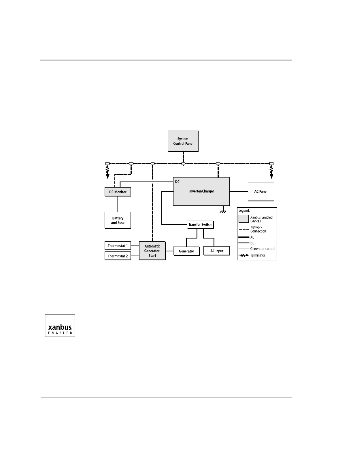
The Xanbus® system includes the RS3000 and other Xanbus-enabled
devices. The RS3000 is the device in a Xanbus system that typically
provides network power—800 mA at 15 volts DC. All of the Xanbusenabled devices, such as the RS3000, the System Control Panel (SCP),
and the Automatic Generator Start (AGS) are able to communicate their
settings and activity to each other. See Figure 1-1.
AC Out
AC In
Figure 1-1
Typical Xanbus System Diagram
Xanbus Enabled
The Xanbus-enabled designation means that this product works on a
Xanbus network. Xanbus-enabled products are:
• Easy to use. The Xanbus network simplifies operation and automates
routine tasks.
• Reliable. Software control eliminates analog signalling errors.
• Accurate. Digital information is less susceptible to interference and
line loss.
• Upgradeable. Software upgrades mean your purchase will remain up
to date.
For detailed instructions and a complete list of Xanbus-enabled devices,
visit www.xantrex.com
975-0170-01-01 1–5
Page 24

Introduction
Comprehensive Electronic Protection
RS3000 is approved to meet a number of safety standards including
UL 458 and CSA C22.2 No. 107.1. See “Regulatory Approvals” on
page A–5 for more information.
RS3000 is equipped with numerous protection features to ensure safe
operation.
Protection feature This feature…
Battery over-voltage
protection
Battery under-voltage
protection
Over-temperature
protection
Automatic overload
protection
Short circuit protection Protects the unit by shutting it down.
Keeps the battery voltage from getting too high in
charge mode. Shuts the inverter off in invert mode.
Prevents inverter from discharging your batteries
too low. The inverter doesn’ t run if battery voltage is
too low.
Protects the unit from overheating by either derating
(charge mode) or by shutting down (invert mode).
See “Invert Power Derating vs Ambient
Temperature” on page A–6.
Protects the unit from excessive loads. The unit will
provide 7500 watts (2.5 times of the rated load) for
up to 5 seconds, and then protect itself by shutting
down. See “Inverter Specifications” on page A–2
for more information.
1–6 975-0170-01-01
Page 25
RS3000 Features
Front Panel Features
Before you begin to operate the RS3000, review the front panel features
shown in Figure 1-2 and described in Table 1-1. A detailed view of the
lights and buttons on the front panel is shown in Figure 1 -3 and d escribed
in Table 1-2.
Introduction
4
2
3
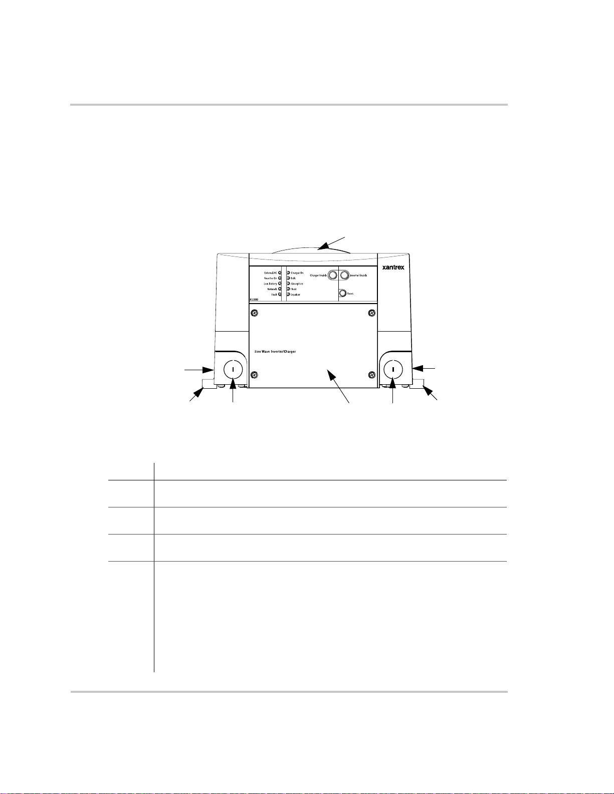
Figure 1-2
Table 1-1
Feature Description
1 AC wiring compartment access panel provides access to the terminal block for
wiring the AC input and AC output.
2 AC knockouts provide access for AC input and AC output wiring. A total of four
knockouts are provided on the unit: two on the front and one on each side (not shown).
3 Mounting flanges are used for mounting the unit. A total of six flanges are provided
on the unit.
4 Fans are used to keep the unit cool.
• The top external fan is an intake fan.
• The to p int e rnal fan (not shown) is an exhaust fan.
Both of these fans activate when the internal temperature of the inverter/charger
increases. The fan speed varies with the internal temperature and turns off when
the inverter/charger cools down. (This internal temperature may be caused by heat
in the inverter/charger or by high ambient temperature.)
• The bottom internal fan (not shown) is an exhaust fan and runs continuously if the
unit is inverting or charging.
2
Front Panel of the RS3000
Front Panel Features
1
2
2
3
975-0170-01-01 1–7
Page 26
Introduction
5
4
3
2
1
10
7
6
8
9
11
12
13
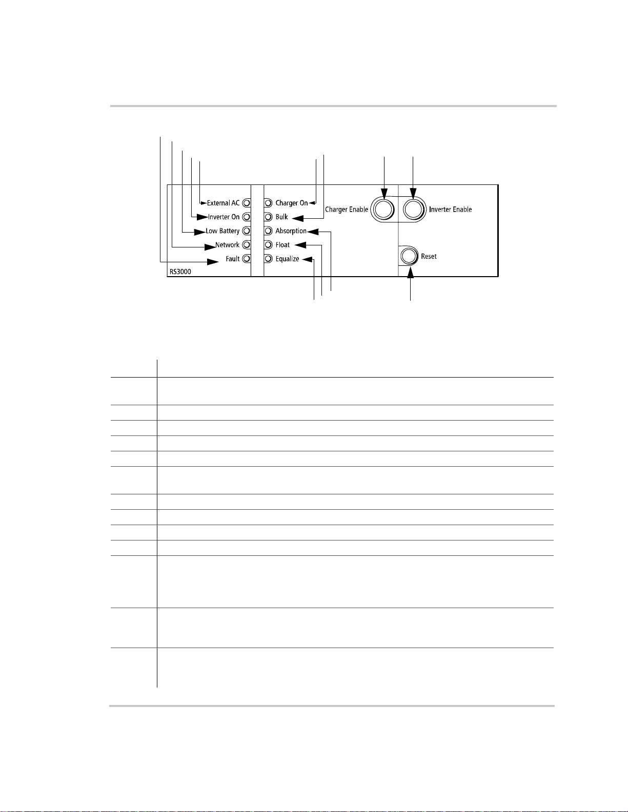
Figure 1-3
Table 1-2
Feature Description
1 External AC light illuminates when you are connected to an AC source like the utility grid or
2 Inverter ON light illuminates when the RS3000 is operating in invert mode.
3 Low Battery light illuminates when the battery voltage is low.
4 Network light illuminates when there is activity on the network.
5 Fault light illuminates if a fault condition occurs.
6 Charger ON light illuminates when the RS3000 is in charge mode and is producing DC output
7 Bulk light illuminates when the charger is in the bulk stage of battery charging.
8 Absorption light illuminates when the charger is in the absorption stage of battery charging.
9 Float light illuminates when the charger is in the float stage of battery charging.
10 Equalize light illuminates when the unit is equalizing the batteries.
11 Charger Enable button toggles between enable (On) and disable (Off). The Charge Enable
12 Inverter Enable button toggles between enable (On) and disable (Off). The Inverter Enable
13 Reset button is used for several functions: to reset after a fault, to perform a power on reset, to
Front Panel Lights and Buttons
Description of Front Panel Lights and Buttons
a generator and the AC is qualified.
to charge your batteries.
button illuminates when the charger is enabled and it can produce DC output to charge your
batteries. When the charger is disabled, it does not produce DC output to charge your batteries,
but still passes AC input through to AC loads (if present).
button illuminates when the inverter is enabled and it can produce AC output to run your AC
loads. When the inverter is disabled, it does not produce AC output to run your loads.
wake the RS3000 from Power Save mode or Hibernate mode. See “Operating in Invert Mode”
on page 2–6 for a description of the different modes.
1–8 975-0170-01-01
Page 27
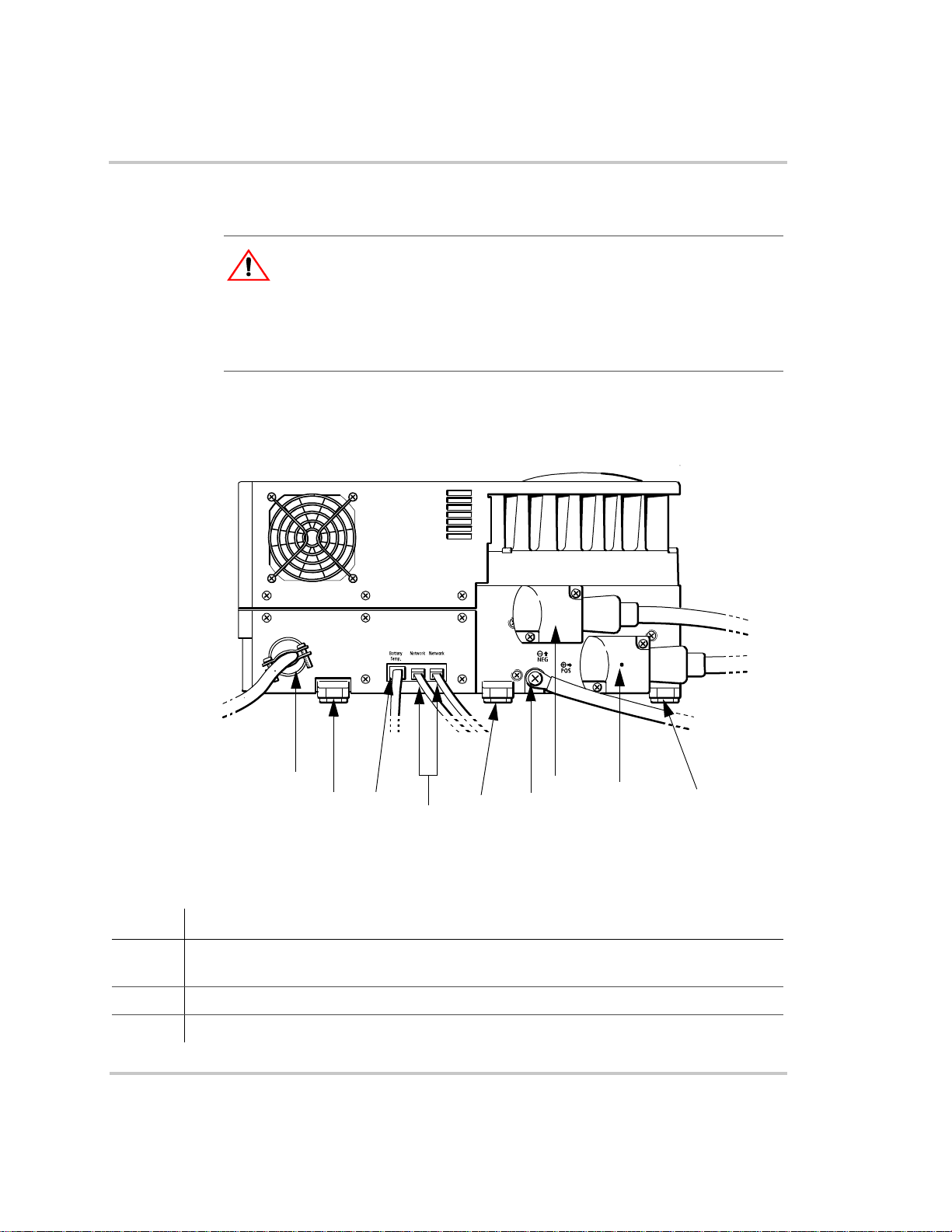
Side Panel Features
CAUTION: Equipment Damage
Connect only to other Xanbus compatible devices.
Although the cabling and connectors used in this network system are the same as
Ethernet connectors, this network is not an Ethernet system. Equipment
damage may result from attempting to connect two different systems.
For your reference, the side panel features with all connections completed
is shown in Figure 1-4.
Introduction
1
2
3
5
7
6
8
9
4
Figure 1-4
Table 1-3
Feature Description
1 AC knockout provides access for AC input and AC output wiring (shown with strain-relief
2, 5, 9 Mounting flanges are used for mounting the unit. A total of six flanges are on the unit.
3 Battery temperature sensor jack provides connection for the battery temperature sensor.
975-0170-01-01 1–9
Completed Connections on Side Panel
Description of Side Panel Features
clamp installed). There are four knockouts on the unit: two on the front and two on the side.
Page 28

Introduction
Table 1-3
Feature Description
4 Dual network jacks provide connection for network-enabled devices. (The number of
6 Chassis ground point connects the chassis of the RS3000 to your system’s chassis grounding
7 & 8 DC terminals – negative (black) (7) and positive (red) (8) —shown here with DC covers on.
Description of Side Panel Features
connections depends on your layout. Your connections may not be the same as shown here.)
point.
1–10 975-0170-01-01
Page 29
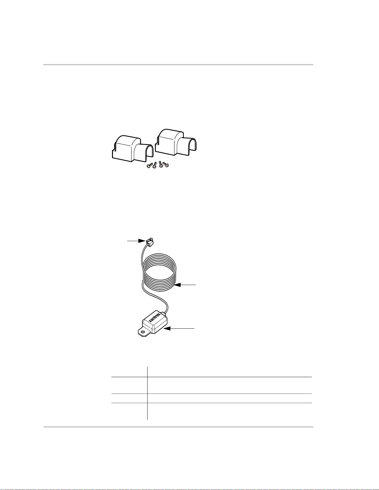
DC Terminal Covers and Battery Temperature Sensor
DC Terminal Covers
Two covers are supplied to prevent accidental contact with the cabling
connectors after installation. The red cover is for the positive cabling
terminal, and the black cover is for the negative cabling terminal.
Introduction
Figure 1-5
Battery Temperature Sensor
The battery temperature sensor continuously measures the temperature of
the battery and adjusts the charger output for a more accurate,
temperature-compensated charge.
3
Figure 1-6
Battery Terminal Covers
2
1
Battery Temperature Sensor
Table 1-4
Feature Description
1 Sensor can be mounted on the side of the battery case or on the
2 Sensor cable is 25 feet (7.6 meters).
3 Connector plugs into the Battery Temp. jack (battery
975-0170-01-01 1–11
Description of Battery Temperature Sensor Features
negative battery terminal.
temperature sensor) on the RS3000.
Page 30
Introduction
System Accessories and Network Components
System accessories can be used with the RS3000 in a Xanbus system. The
System Control Panel (SCP) provides configuration and monitoring
capability for Xanbus-enabled devices such as the RS3000. Automatic
Generator Start (AGS) automatically starts and stops your generator.
Table 1-5 provides the part numbers for the system accessories.
Table 1-5
Accessory Part number
System Control Panel (SCP) 809-0910
Automatic Generator Start (AGS) 809-0915
System Accessories
Consult with your local system designer to determine what network
components will be needed for your specific installation. Table 1-6
provides a list of network components and part numbers. Pre-made cabl es
are available in standard lengths ranging from 3 feet to 75 feet.
Table 1-6
Network Component Part Number
Network termination — Male (2 per pack) 809-0901
3-way network connector 809-0903
Network termination — Female (2 per pack) 809-0905
Network cable 3 ft. (0.9 m) 809-0935
Network cable 5 feet (1.5 m) 809-0936
Network cable 7 feet (2.0 m) 809-0937
Network cable 10 feet (3.0 m) 809-0938
Network cable 14 feet (4.3 m) 809-0939
Network cable 25 feet (7.6 m) 809-0940
Network cable 50 feet (15.2 m) 809-0941
Network cable 75 feet (22.9 m) 809-0942
Network Components and Part Numbers
These accessories and network components are available from any
authorized Xantrex dealer or at www.xantrex.com. Detailed information
on planning and installing your network is available in the Xanbus System
Installation Guide. This guide is available for downloading at
www.xantrex.com
1–12 975-0170-01-01
Page 31
2
Operation
Chapter 2, “Operation” contains detailed information and
procedures for using your RS3000.
If you’re using the System Control Panel to operate or monitor
the status of the unit, also refer to the System Control Panel
Owner’s Guide.
WARNING: Restrictions on use
RS3000 Sine Wave Inverter/Charger shall not be used in connection with life
support systems or other medical equipment or devices.
CAUTION
Read this chapter before operating the RS3000 Sine Wave Inverter/Charger.
Page 32

Operation
Operating the RS3000 with the System Control Panel
The System Control Panel (SCP) provides operating, configuration, and
monitoring capability for your Xanbus system.
The System Control Panel:
• Monitors activity throughout your onboard power system.
• Displays the latest information about your inverter/charger, battery
charge level, battery charge output, and generator start and stop
activity.
• Displays the settings for each Xanbus-enabled device in the system.
• Enables you to adjust the settings for each Xanbus-enabled device in
the system.
• Preserves all of its settings if system power is interrupted. After
power is restored, you don’t have to reconfigure the SCP or any of the
Xanbus-enabled devices connected to it.
This section provides information on operating the RS3000 with the
System Control Panel. Please refer to the System Control Panel Owner’s
Guide for complete information on using the System Control Panel.
Important:
be saved in the SCP if the unit is shut down by selecting Power Save mode, Safe
mode or Hibernate mode. See “Operating in Invert Mode” on page 2–6 for more
information about the different types of modes.
Any RS3000 setting changed from the System Control Panel will
2–2 975-0170-01-01
Page 33

Operation
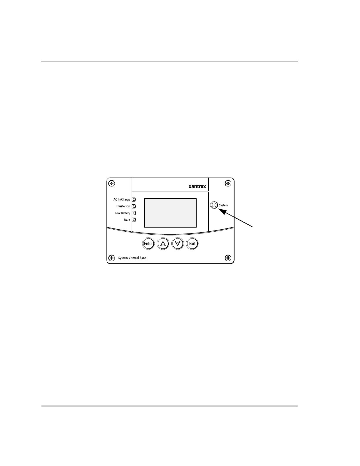
Using the System Control Panel
The System Control Panel has important features which you’ll want to be
familiar with, as shown in Figure 2-1.
Display screen System information is shown on the display screen with an adjustable
backlight.
Indicator lights Four indicator lights on the front panel indicate the operating status of the
Xanbus system.
Push buttons Four push buttons allow you to select device menus and change or display
settings. The red System button toggles the System Control Panel and
Xanbus-enabled devices between Operating mode and Power Save mode.
For more information on the different system modes, see “Operating in
Invert Mode” on page 2–6.
9
1
1
2
3
4
10
6
5
Figure 2-1
Table 2-1
Feature Description
1 AC In/Charge light indicates that qualified AC is present at
2 Inverter On light illuminates when the RS3000 is enabled
3 Low Battery light illuminates when the battery voltage on the
975-0170-01-01 2–3
System Control Panel
System Control Panel Features and Buttons
the input of an inverter/charger. When the RS3000 is
connected to a qualified AC source like the utility grid or a
generator, this light on the System Control Panel illuminates.
(turned on).
RS3000 is low.
8
7
Page 34

Operation
Table 2-1
Feature Description
4 Fault light indicates a condition that requires user attention
5 Enter button
6 Up arrow button
7 Down arrow button
8 Exit button
9 System button:
10 Screen displays menus, settings, and system information.
System Control Panel Features and Buttons
and intervention. The Fault light illuminates when any
Xanbus-enabled device connected to the network is in fault.
See “Faults and W arnings” on page 4–2 for the definitions of a
fault and warning.
• Confirms selection of a menu item.
• Moves you to th e next screen.
• Scrolls up one line of text.
• Increases a selected value.
• Scrolls down one line of text.
• Decreases a selected value.
• Cancels selection of a menu item.
• Returns yo u to the previo us screen.
• Toggles all Xanbus-enabled devices on the system between
Operating mode and Power Save mode. See “Operating in
Invert Mode” on page 2–6.
On Start Up
When the RS3000 is powered up or has been reset, all of the front panel
lights illuminate and remain on for a minimum of five seconds. After five
seconds, the lights remain illuminated until the front panel has status
information for all the lights.
The RS3000 inverter is disabled every time the RS3000 is powered up.
After powerup, the Inverter Enable button or the System Control Panel
can be used to enable or disable the inverter. The powerup behaviour of
the RS3000 charger is determined by the 'Force Charge' setting (see
page 3–23).
When a function is enabled, it is allowed to occur but other conditions
may have to be met before the function is activated or turned on. For
example, the charger function on the RS3000 may be enabled, but it will
not charge unless qualified AC power is present.
2–4 975-0170-01-01
Page 35

System Start-up Check
WARNING
Review the “Important Safety Instructions” on page vii before operating the
inverter/charger.
To test inverting and charging from the RS3000 front panel:
1. Disconnect AC power from inverter input by opening the breaker or
disconnect. Press the Inverter Enable button on the RS3000. The
Inverter On light illuminates.
2. Place a load on the inverter. For example, plug a 100 watt light bulb
into an outlet that the inverter is powering and make sure it works.
The inverter should run the load using battery power.
3. To test the charger, reconnect the AC input power to allow AC to the
AC input. The Charger On light should illuminate after a brief delay.
Any AC loads previously powered by the inverter will also work at
this time.
4. Remove the AC input power. The inverter/charger should trans f er to
invert mode immediately. (The transfer relay will make a clicking
sound and the Inverter On light will illuminate.) Loads should
continue to operate uninterrupted.
Operation
If any part of this test fails, determine the cause before using the unit.
Consult the “Troubleshooting” chapter starting on page 4–1.
Viewing the Firmware Revision Number
You may need to view the firmware revision number of the RS3000 when
troubleshooting the unit with authorized service personnel.
To view the firmware revision number:
1. On the Select Device menu, use the down arrow button to highlight
System and press Enter.
The System Settings menu appears.
2. Press the down arrow button to highlight View Device info and press
Enter.
The Device Info screen appears.
3. Press the down arrow button un til the RS3000 screen appears.
The number opposite “F/W Rev.” is the firmware revision number.
4. Press Exit to return to the System Settings menu.
975-0170-01-01 2–5
Page 36

Operation
Operating in Invert Mode
WARNING
Review the “Important Safety Instructions” on page vii before operating the
inverter/charger.
Once the inverter/charger is installed, you can operate it in invert mode.
To operate in invert mode from the front panel:
1. Press the Inverter Enable button on the RS3000.
2. If external AC is present, the External AC light illuminates. If AC is
present and you want to operate the inverter, remove AC so the
inverter turns on.
Once the Inverter On light is on, the RS3000 inverter is ready to
deliver AC power to the loads.
◆ To operate the inverter with the System Control Panel, refer to
Chapter 2, “Using the System Control Panel”.
Load Sense Mode
Important:
“Inverter Applications” on page 4–16.
The load sense mode of the RS3000 reduces battery power consumption
in order to conserve battery capacity.
When the inverter is enabled, the inverter/charger can be configured to
search for an acceptable AC load. (It does this when you enable (turn on)
“Load Sense” on the RS3000 Advanced Menu on the System Control
Panel and set the load sense power threshold “Sense Below.”)
The inverter output turns off if the unit doesn’t detect a load that meets the
load sense parameters. When an acceptable load is detected, the inverter
output is turned on and provides continous output power. When the
loadsense feature is disabled (turned off), the inverter is continuously on.
The unit will “sleep” if it doesn’t detect a load that meets the load sense
parameters. If a load exceeds the “Sense Below” threshold set in the
RS3000 advanced menu, the RS3000 will “wake up” and deliver full
power to the load.
If you are having problems with any of your loads, refer to
2–6 975-0170-01-01
Page 37

Operation
Operating Limits for Inverter Operation
Power Output
T emperatu re The RS3000 produces 120 volts AC at up to 3000 watts. The RS3000 can
deliver this power in an ambient (surrounding) temperature up to 122 °F
(50 °C). In higher ambient temperatures, if the loads draw full power for
an extended period of time, the unit may shut down to protect itself
against overheating.
As with all inverters, the amount of continuous power that the RS3000
can deliver without overheating is limited by the ambient air temperature.
The RS3000 will operate and deliver its continuous power rating at higher
temperatures, but the ambient temperature as well as the input voltage
from the battery will limit the extent to which the unit can run
continuously.
The RS3000 has 7500 watt surge for five seconds. Operating the
inverter/charger in conditions outside of power and temperature limits,
however, will result in thermal shutdown and/or significantly decreased
performance. In addition, operation in this range is outside the ratings
covered by the regulatory approvals of the product. See “Invert Power
Derating vs Ambient Temperature” on page A–6.
Difficulty on
starting loads
The inverter/charger should be able to operate all AC loads rated at or
below its power rating. Some high horsepower induction motors used in
pumps and other motor-operated equipment require very high surge
currents to start, and the inverter/charger may have difficulty starting
these loads. See “Inverter Applications” on page 4–16.
If you have problems starting certain loads, ensure that:
• the battery connections are tight and clean
• the DC cabling is no longer than the recommended length. Refer to
the RS3000 Sine Wave Inverter/Charger Installation Guide for this
information.
• the AC wiring is of recommended size. Refer to the RS3000 Sine
Wave Inverter/Charger Installation Guide for this information.
• the battery is of sufficient capacity and is fully charged.
975-0170-01-01 2–7
Page 38

Operation
Operating in Charger Mode
WARNING: Explosive Gases
Review the “Important Safety Instructions” on page vii before operating the
inverter/charger. During charging, batteries may generate explosive gases.
Thoroughly ventilate the areas around the batteries and ensure that there are no
sources of flames or spark in the vicinity.
Study all battery manufacturer’s precautions such as removing or not removing
cell caps while charging and the recommended rates of charge.
Important:
distilled water in each cell. The battery acid should be at the level specified by
the battery manufacturer. This helps prevent over-heating and purges excessive
gases from the cells. Do not overfill. For a battery without cell caps, follow the
manufacturer’s recharging instructions carefully.
If you are charging a non-sealed battery, ensure there is sufficient
To operate the RS3000 in charger mode from the front panel:
1. Connect AC input power.
The charger automatically starts up when qualified AC power is
connected if the charger is enabled, or the charger is disabled but the
Force Charge enable override is On. See “Force Charge” on page 3–
23.
• The batteries are charged according to the two-stage or three-
stage formula you have selected on the System Control Panel.
(See “Battery Charging Reference” on page B–1 for more
information on two-stage or three-stage charging.)
• You can interrupt the charge cycle any time you desire by
disabling the charger from the System Control Panel or by
pressing the Charger Enable button (on the front panel of the
RS3000) so it is no longer illuminated.
• To maintain optimal performance in flooded batteries, an
occasional equalize cycle may be required. See “Operating in
Equalization Mode” on page 2–10.
• While the batteries are being charged, you can monitor which
stage they are in from the front panel of the RS3000 or from the
System Control Panel.
◆ To operate the charger with the System Control Panel, refer to
Chapter 3, “Configuration”.
2–8 975-0170-01-01
Page 39
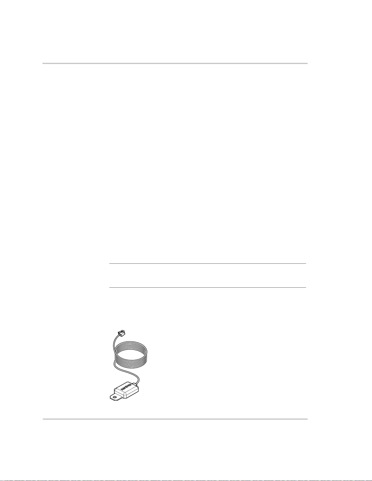
Charger Operation with Battery Temperature Sensor
Since battery temperature is a key factor in correct charging, the charging
formula must be adjusted (automatically and in real time) according to the
actual battery temperature to ensure that batteries are fully charged, but
not overcharged. For this reason, Xantrex has included a battery
temperature sensor (see Figure 2-2) with your RS3000 Sine Wave
Inverter/Charger and has temperature compensated the charge formula.
The battery temperature sensor continuously measures the temperature of
the battery and adjusts charger output for a more accurate, temperaturecompensated charge.
When batteries are cold, their chemical reaction is sluggish, meaning they
don’t absorb charge as easily. Thus a charge level optimized for room
temperature will not charge the batteries sufficiently if they are cold. The
charger must compensate by increasing its voltage to achieve the
compensated equivalent of a room temperature charge. If the batteries are
hot, the chemical reaction is hyperactive and they absorb energy too
easily; thus a standard room-temperature charge would tend to overcharge
a hot battery. Therefore, the charger compensates by reducing its voltage.
The battery temperature sensor automatically, and in real time, makes
adjustments to the charger’s voltage setpoints to properly charge your
batteries. The actual charge compensation formula can be found on
page A–3.
Operation
Important:
setpoint when charging if the battery case temperature is above or below 77 °F
(25 °C)
It is normal to see a voltage that is different than the specified
If a battery temperature sensor is not present, the RS3000 uses the hot
setting, the default value, unless the setting has been adjusted during
configuration. Charging may not be effective at extreme temperatures.
See “Charger Specifications” on page A–3.
Figure 2-2
975-0170-01-01 2–9
Battery Temperature Sensor
Page 40

Operation
Operating in Equalization Mode
WARNING: Explosive gases
Equalization generates explosive gases. Ensure adequate ventilation.
CAUTION: Batteries may be damaged
Sealed lead-acid batteries and gel batteries must NEVER be equalized or
premature battery failure will result. Equalize mode is disabled if you have
selected “Gel” and “AGM” as the battery type.
Only flooded (wet) lead-acid batteries should be equalized. As a general rule, do
not equalize a battery unless there are provisions to add water to it and the
manufacturer recommends equalization.
If carried out too frequently or done improperly, equalization can damage your
batteries. Never equalize a battery more than necessary . Always check electrolyte
level before AND after equalization. Fill with distilled water per the battery
manufacturer’s recommendation.
CAUTION: Risk of damage to DC load equipment
Equalization voltage may be as high as 15.8 volts DC. Disconnect sensitive loads
from the battery before equalizing.
Follow the battery manufacturer’s recommendations for equalizing your
batteries. As a guide, a heavily used flooded battery may need to be
equalized once a month, and a battery in light service may only need to be
equalized every two to four months.
Measure the specific gravity (S.G.) of each cell using a hydrometer. For
fully charged lead-acid batteries, the reading should be approximately
1.265. Low specific gravity after charging or a 0.25 difference from cell
to cell indicates the need for equalization.
2–10 975-0170-01-01
Page 41

Equalizing Batteries
Operation
Important:
Equalization only runs for 60 minutes and may need to be restarted if the
specific gravity is still uneven.
To equalize your batteries:
1. Turn off or disconnect all loads on the battery.
The voltage applied to the battery during equalization may damage
your electronic equipment. As well, equalization won’t proceed
correctly if loads are drawing current from the battery.
2. Check electrolyte level.
Fill with distilled water if the electrolyte level is low.
3. To request the equalization charge, ensure the Charger is enabled.
4. On the System Control Panel, select Equalize on the RS3000 home
menu. For detailed information on configuring this setting, refer to
“Equalize” on page 3–14.
5. When equalization is finished, check the battery electrolyte level. T op
up as necessary with distilled water only and recheck the specific
gravity as specified by the battery manufacturer.
Equalization will be carried out after an absorption charge.
Terminating the Equalization Process
The equalization process can be terminated in three ways:
• user cancellation from the System Control Panel, as shown in Figure
3-12 on page 3–16
• inverter/charger cancellation if AC is removed or the charger is
disabled
• successful completion of the equalization process.
975-0170-01-01 2–11
Page 42

Operation
Operating Limits for Charger Operation
The maximum output current for the RS3000 is 150 amps. You can
reduce the total output if you change the “Max Chg Rate” setting on the
RS3000 Advanced Menu or the maximum “Power Share”setting on the
RS3000 Basic Menu.
The charger can oper ate over an AC i nput range of 90– 135 volts AC. This
is the default setting and can be adjusted to 85–145 volts AC as a
maximum range and to 110–120 volts AC as a minimum range.This wide
range allows the RS3000 to charge your batteries even when incoming
AC voltage is less than ideal.
Power Share
The RS3000 charger uses AC input line 1 to charge the batteries. The
RS3000 charger shares incoming power with AC loads on line 1 only. The
AC loads have priority, which means that the charger will reduce its
output with large AC loads and increase the output again when the AC
load decreases. The regulatory maximum for continuous AC loads is 80%
of the breaker rating that the loads are connected to.
The RS3000 senses pass-through current going to the AC load. The
difference between the pass-through (load) and 80% of the Power Share
setting is the current that is available for charging the batteries.
For example, if the AC input of the RS3000 is from an AC panel with a
30A breaker, the Power Share setting on the System Control P anel should
be selected as 30A. Based on this, the charger will control the charge
current so that the total current draw is equal to or less than 24A in this
case. Should the load current be more than about 24A, the charger output
will reduce to 0A, but the RS3000 will continue to supply the loads. The
RS3000 will continue to pass-through power to the loads, even if the load
current exceeds the Power Share setting. In this case, it will be up to the
user to remove/disconnect loads if tripping the AC input breaker
supplying the RS3000 is to be avoided.
2–12 975-0170-01-01
Page 43

Monitoring the RS3000 Indicator Lights
The ten indicator lights on the front panel show you the operating status
of the RS3000. A description of the lights is provided in Table 2-2.
If none of the front panel lights are on, see “Troubleshooting Reference”
on page 4–4.
Operation
Table 2-2
Light Illuminated Color Status Action or Status Item
External AC Green When the RS3000 is connected to a
Inverter ON Green When the RS3000 is enabled (on)
Low Battery Yellow When the Low Battery light
Network Green Indicates that there is activity on the
Fault Red A fault has occurred on the
Charger ON Green When the RS3000 is in charge
Front Panel Lights
qualified AC source or a generator,
the External AC light illuminates.
and producing AC or load sensing,
the Inverter ON light illuminates.
This light is not illuminated if the
unit is charging.
illuminates, the battery level is low.
network.
network.
mode, the Charger ON light is
illuminated. In three-stage charging,
charging occurs in 3 stages: bulk,
absorption, and float. One of these 3
lights will be illuminated at the
same time the Charger ON light is
illuminated.
If the Charger ON light is off, the
RS3000 is not in any charge mode.
You can run your appliances
from an AC source like the
utility grid or a generator.
You can run your appliances
from the inverter.
Y ou can run your appliances but
your battery level is low. Charge
your battery or connect to an
AC source or turn off the
inverter.
Communication on the network
Investigate and clear the fault
condition.
The charger is active and
charging your batteries. The
Charger ON light is always
illuminated if charging, whether
the unit is putting out current or
not.
975-0170-01-01 2–13
Page 44

Operation
Table 2-2
Light Illuminated Color Status Action or Status Item
Bulk Green RS3000 is in bulk m ode of battery
Absorption Green RS3000 is in absorption mode of
Float Green RS3000 is in float mode of battery
Equalize Yellow RS3000 is in equalize mode of
Front Panel Lights
charging.
battery charging.
charging. The Float light
illuminates in three-stage charging.
battery charging.
These lights indicate which
state of charge the RS3000 is in.
Faults and Warnings
A fault affects the operation of the unit. A manual fault requires user
intervention by clearing the condition and then pressing the Reset button
on the inverter/charger’s front panel. See the System Control Panel
Owner’s Guide for information on clearing faults from the System
Control Panel.
A warning alerts you to a condition that could possibly affect operation of
the unit.
See “Faults and Warnings” on page 4–2 for more explanation on the
difference between faults and warnings.
Monitoring Status Messages on the System Control Panel
Refer to “System Menu Map” on page 3–3 of the Configuration chapter.
2–14 975-0170-01-01
Page 45
System Modes
Operation
This section provides an overview of the four different system modes.
The system modes described in this section affect the performance and
behavior of the RS3000 and all other Xanbus-enabled devices on the
Xanbus system. You’ll have to change the system mode when travelling,
putting your vehicle in storage, or when installing a Xanbus-enabled
device.
You can change system modes using the System Settings menu on the
System Control Panel.
You can also use the red System button on the System Control Panel to
put the System Control Panel and all other Xanbus-enabled devices into
Power Save mode only.
System
button
Figure 2-3
System modes are changed using the System Settings menu. The four
system modes are:
• Operating
• Power Save
•Safe
• Hibernate
Please read the section about each system mode to find out which mode is
appropriate for different conditions or situations.
975-0170-01-01 2–15
System Control Panel
Page 46
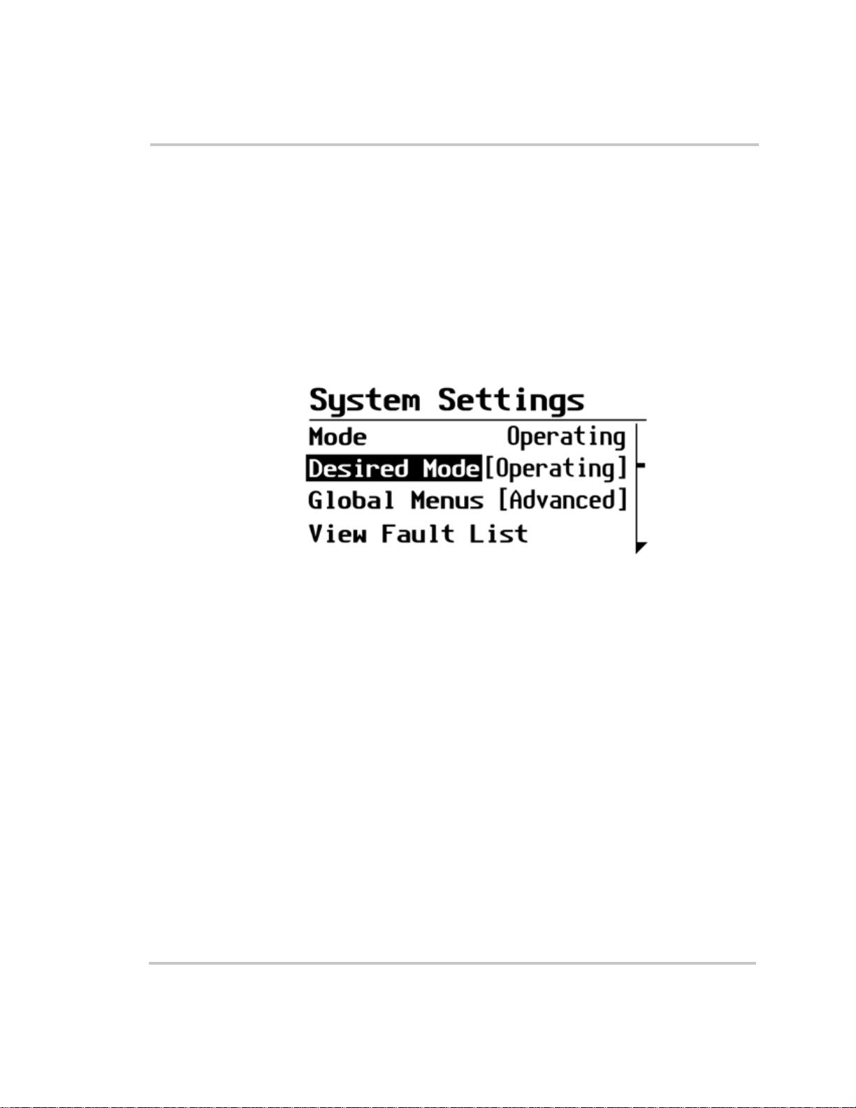
Operation
Operating Mode
Characteristics In Operating mode, all communications are enabled on the Xanbus
system. All power conversion functions are enabled. Each Xanbusenabled device is monitoring and communicating its input.
The basic state of the System Control Panel is Operating mode. In
Operating mode, the System Control Panel communicates with other
Xanbus-enabled devices and displays all the network information which it
is configured to display.
Whenever the System Control Panel or any other device on the Xanbus
system is powered on or reset, it will be in Operating mode.
Figure 2-4
Operating Mode
Power Save Mode
Characteristics Power Save mode minimizes power draw by the System Control Panel
and other Xanbus-enabled devices on the Xanbus system. Power Save
mode stops all communication on the network and disables the power
conversion functions of Xanbus devices. For example, in Power Save
mode, the inverter/charger will not invert and an Automatic Generator
Start will not start a generator.
When to use Use Power Save mode during periods when your power needs are
minimal—while you are driving, for example. Putting the system in
Power Save mode will help preserve the charge in your batteries during
periods of minimal power usage.
Entering and exiting Power Save mode also serves as a “reset” command
for the system.
If there are active faults in the system, you cannot put the system into
Power Save mode. Clear any active fault, correct the condition that
caused the fault, then put the system into Power Save mode.
2–16 975-0170-01-01
Page 47
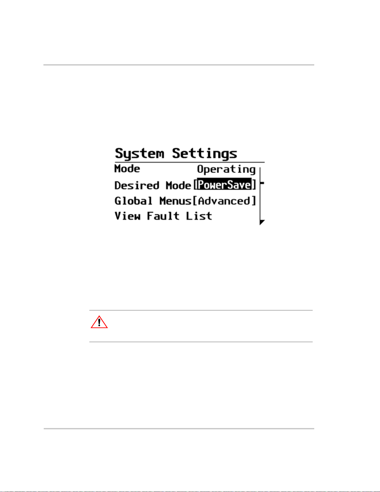
Operation
To enter or exit Power Save mode:
◆ Press and hold the System button on the System Control Panel for one
second.
After you release the System button, the System Control Panel screen
and indicator lights will turn off.
You can also enter or exit Power Save mode on the System Settings
menu by selecting Desired Mode and scrolling to PowerSave as
shown in Figure 2-5.
Returning to
Operating mode
Figure 2-5
If an inverter/charger supplies power to the network, applying AC input
with utility power or generator power automatically returns the system to
Operating mode.
Power Save Mode
Safe Mode
CAUTION: Unexpected behavior
Before installing or removing a device on the network, put the network into Safe
mode. Putting the network into safe mode prevents unexpected behavior.
Characteristics Selecting Safe mode stops the generator (if it is running) and puts the
System Control Panel (and all Xanbus-enabled devices) into Safe mode.
While in Safe mode, the System Control Panel remains powered,
“listening” to and reporting its status to the network. However, the ouptut
power of all Xanbus-enabled devices is disabled and all inverting,
charging, and generator starting activity stops. In Safe mode, the RS3000
will not transfer AC power from a source.
975-0170-01-01 2–17
Page 48

Operation
In Safe mode, the RS3000 continues to communicate, but the inverting
and charging functions are disabled.
When to use Use Safe mode when you are adding or removing devices from the
network. Authorized service personnel must also put the System Control
Panel in Safe mode before performing software upgrades and diagnostics
with the Xantrex Diagnostic Tool.
If the System Control Panel is powered off while in Safe mode, it will be
in Safe mode when it is powered up again.
To return to Operating mode:
◆ On the System Settings menu, under Desired Mode, select
“Operating.”
Putting the System into Safe Mode
When you are installing or removing devices from the Xanbus system,
putting the system into Safe mode prevents unexpected behavior.
To enter Safe mode:
1. On the Select Device menu, use the down arrow button to highlight
System.
The cursor on the right of the screen indicates where you are in the
menu.
Figure 2-6
Select Device Menu
2. Press Enter.
The System Settings menu appears.
2–18 975-0170-01-01
Page 49

Operation
Figure 2-7
System Settings Menu
3. On the System Settings menu, with Desired Mode highlighted, press
Enter.
4. Use the down arrow button to scroll through the other modes to select
Safe mode.
For more information on the different system modes: Operating,
Power Save, and Hibernate see “Operating in Invert Mode” on
page 2–6.
Figure 2-8
Safe Mode
5. Press Enter.
You are now in Safe mode.
6. Press Exit twice to return to the System Home Screen.
To exit Safe mode and return to Operating mode:
1. On the System Settings menu, under Desired Mode, select
“Operating.”
2. Press Enter.
975-0170-01-01 2–19
Page 50

Operation
Hibernate Mode
Characteristics Hibernate mode removes network power from the System Control Panel
and all Xanbus-enabled devices on the Xanbus system. The System
Control Panel suspends all operations (including starting and stopping the
generator) until power is restored to the network. All Xanbus-enabled
devices other than the RS3000 have no network power.
When to use Use Hibernate mode when the Xanbus system is left unattended for long-
periods of time to prevent any unattended system activity and to prevent
battery drain during long periods of inactivity.
The system will automatically enter Hibernate mode if it is in Power Save
mode for more than two hours.
Important:
Hibernate mode from the System Control Panel before putting your RV or boat
into storage.
To prevent any unattended system activity, put the system into
If there are active faults in the system, you cannot force the system into
Hibernate mode. Clear any active faults, correct the condition that caused
the fault, then put the system into Hibernate mode.
Restoring power Once in Hibernate mode, the System Control Panel cannot return the
System to Operating mode. You must restore power to the network by
pressing the Reset button on the RS3000 front panel for several seconds.
When the RS3000 has been reset, all of the front panel lights illuminate
and remain on for a minimum of five seconds. After five seconds, the
lights remain illuminated until the front panel has status information for
all the lights.
If an inverter/charger supplies power to the network, you can bring the
system out of Hibernate mode either by pressing the reset button on the
inverter/charger front panel or by applying AC input with utility power or
generator power.
2–20 975-0170-01-01
Page 51

3
Configuration
Chapter 3, “Configuration” contains information about all
configurable settings and procedures for the RS3000.
This chapter provides information on using the SCP to
configure the RS3000 settings. Please refer to the System
Control Panel Owner’s Guide for detailed information on how
to use the SCP.
Page 52

Configuration
General Configuration Information
System Control Panel
The System Control Panel provides configuration and monitoring
capability for all Xanbus-enabled devices on the network. All changes to
the configuration of the RS3000 are made with the System Control Panel
(SCP). See “Using the System Control Panel” on page 2–3.
The front panel of the RS3000 provides limited control, including reset;
charger enable and disable; and inverter enable and disable.
Enabling a function When a function is enabled, it is allowed to occur but other conditions
may have to be met before the function is activated or turned on. For
example, the charger function on the RS3000 may be enabled, but it will
not charge unless qualified AC power is present.
Disabling a function When a function is disabled, it is not allowed to occur and if it is
occurring, it is terminated. Regardless of other conditions, the function
will not be activated. For example, even if AC power is present, if the
charger is disabled, the unit will not charge.
These functions can also be controlled from the System Control Panel.
3–2 975-0170-01-01
Page 53

System Menu Map
Figure 3-1 provides a map of how the System Control Panel screens and
menus are organized. The order of devices appearing on the System
Control Panel will vary, depending on the order in which they’ve been
connected to the network.
Power Up
Startup screen
Startup screen
Standby Charg ingInverting Load Se nseAC Bypass Equalize
Select Device
Select Device
Enter
menu
menu
Enter
Exit
Exit
Inverter/Charger
Inverter/Charger
System screen
System screen
menu
menu
Configuration
Device menus
Figure 3-1
Auto Gen Start menu
Auto Gen Start menu
Syste m Pane l m e nu
Syste m Pane l m e nu
Clock menu
Clock menu
System Settings
System Settings
menu
menu
System Menu Map
Optional device. This menu will
=
appear if this device is installed.
975-0170-01-01 3–3
Page 54

Configuration
Viewing the System Screen
The System screen displays system activity. The information appearing
on the System screen varies with the status of the inverter/charger:
Standby, Inverting, Charging, AC Bypass, Load Sense or Equalize. See
“Modes” on page 3–10 for an explanation of the different modes. For
example, Figure 3-2 shows the RS3000 in the float stage of charging.
You cannot select or change any of the information on the Syst em screen .
If you would like to view more detailed information, press the Enter
button (indicated by the menu arrow) to go to the Select Device menu.
Figure 3-2
RS3000 Float System Screen (Example)
Viewing the Select Device Menu
The Select Device menu is where you can view a list of all the Xanbusenabled devices in your power system.
To view the Select Device menu:
◆ On the System screen, press Enter.
The Select Device menu appears with RS3000 highlighted, as shown in
Figure 3-3.
3–4 975-0170-01-01
Page 55

Configuration
Figure 3-3
Select Device Menu
Selecting the RS3000 from the Select Device Menu
To select the RS3000 from the Select Device menu:
1. With RS3000 highlighted, press Enter.
The RS3000 menu appears, as shown in Figure 3-4.
Figure 3-4
You can view and change RS3000 settings from the device menu. The
number of settings on the RS3000 menu will depend on whether you have
selected to view basic or advanced menus.
RS3000 Menu in Invert Mode
Selecting the RS3000 Basic Menu
RS3000 basic menu lists status information and settings you may have to
adjust on a routine basis. It provides access to basic control of the
inverter/charger.
975-0170-01-01 3–5
Page 56

Configuration
Selecting the RS3000 Advanced Menu
RS3000 advanced menu lists status information and settings which
require that you understand and plan for the changes you make. You may
not have to adjust these settings as part of regular operation.
The System Control Panel shows the RS3000 basic menu by default. If
you would like to view the advanced menu, you must go to the System
menu and select Global Menus.
Important:
When you set Global Menus to Advanced, the System
Control Panel will display the advanced menus for all devices.T o return to
viewing the basic menu for any Xanbus-enabled devices, select Basic
Menu from the advanced menu for that device.
To select the RS3000 Advanced Menu:
1. On the Select Device menu with System highlighted, as shown in
Figure 3-5, press Enter.
Figure 3-5
Highlighting System on the Select Device Menu
2. Scroll with the down arrow button to highlight Global Menus.
3–6 975-0170-01-01
Page 57

Configuration
Figure 3-6
3. Press Enter.
4. Select Advanced and press Enter.
5. Press Exit to return to Select Device menu.
Returning to RS3000 Basic Menu
You can return to viewing the RS3000 basic menu by selecting Basic
Menu from the RS3000 advanced menu, as shown in Figure 3-7.
Advanced menu items will no longer be visible on the System Control
Panel.
Highlighting Global Menus
Figure 3-7
975-0170-01-01 3–7
Returning to RS3000 Basic Menu
Page 58

Configuration
Selecting and Adjusting the Configurable Settings
You can view or change RS3000 settings from the RS3000 menu. Status
information is not configurable. Configurable settings are indicated by
square brackets [ ] and can be adjusted.
Follow these steps to change any RS3000 setting.
1. On the RS3000 menu, use the up arrow or down arrow button to
highlight the setting you want to change.
2. Press Enter to highlight the valu e of that Configurable setting,
indicated by square brackets [ ].
The previously set value appears with an asterisk beside it, as shown
in Figure 3-4.
3. Use the up arrow or down arrow button to change the value. Holding
down a button lets you scroll through values quickly.
4. Press Enter to select the value.
5. If you have another setting to change, return to step 1.
Or
If you have no more settings to change, press Exit to return to the
Select Device menu.
Selecting the Default Settings
All configurable items on the RS3000 menu items have a default setting.
The default setting is the value which was set at the time the unit was
originally installed.
You can restore individual settings to their default value or you can
restore all values to default settings. See “Restore Defaults Warning” on
page 3–29.
3–8 975-0170-01-01
Page 59
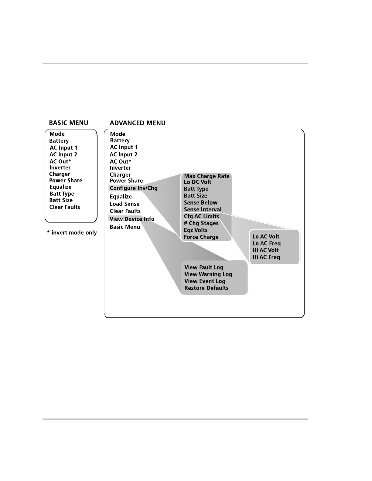
RS3000 Menu Structure
An overview of the RS3000 menu structure is shown in Figure 3-8. The
System Control Panel displays the RS3000 basic menu and advanced
menu.
Configuration
Figure 3-8
975-0170-01-01 3–9
RS3000 Menu Structure — Overview
Page 60

Configuration
RS3000 Device Menu
The RS3000 device menu displays status information on the different
modes of the inverter/charger. The first three or four lines of the device
screen displays dynamic content that changes, depending on what mode
that the RS3000 is in.
Modes
The first line on the device menu indicates which mode that the RS3000 is
in. T a ble 3-1 defines the seven dif ferent modes: Invert, Bulk, Absorption,
Float, AC Bypass (AC Passthru), Load Sense, and Equalize.
Table 3-1
Mode Description
Invert The RS3000 is converting DC power to AC power.
Bulk The first stage of three-stage battery charging. Current is
Absorption The second stage of three-stage battery charging. Voltage
Float The third stage of three-stage battery charging. After the
AC Bypass
(ACPassthru)
Load Sense In order to minimize power draw from the battery, the
Equalize To improve the life and performance of a non-sealed,
Modes
supplied to the batteries at a constant rate while voltage
gradually rises.
remains constant and current reduces as the battery
becomes charged. This ensures complete charging.
batteries reach full charge, charging voltage is reduced to a
lower level to prevent gassing and to prolong battery life.
This stage is often referred to as a maintenance charge.
Rather than charging a battery, it keeps an already-charged
battery from discharging while providing load current.
AC input from an AC source like the utility grid or from a
generator is allowed to pass through the unit to operate
connected AC loads. The charger is not enabled but AC is
qualified as good and passed through the unit.
inverter will periodically check if a load is connected when
the inverter is enabled.
flooded (or wet) battery, the RS3000’s multi-stage charging
cycle includes a manual equalize mode that can be used if
recommended by the battery manufacturer.
3–10 975-0170-01-01
Page 61

Battery
The second line of the device screen indicates the status of the battery.
This line displays the volts (V); current (A) as either (+) positive amps
(indicating that the battery is charging) or (–) negative amps (indicating
the battery is discharging because you’re inverting); and battery
temperature in either
AC Input1 and A C Input2
When the RS3000 has external AC input connected, these AC display
lines indicate the status of the AC input. Each AC display line shows the
values for current (A), frequency (Hz), and the AC voltage in (V).
AC Out
This line is displayed only when the RS3000 is in invert mode. This line
indicates the AC output and shows the values for
current (A), the frequency (Hz), and the AC voltage in (V).
Configuration
°F or °C.
975-0170-01-01 3–11
Page 62
Configuration
RS3000 Menu (Basic)
The RS3000 basic menu indicates the status of items and lists settings that
you may have to adjust on a routine basis.
If advanced menu is enabled, scroll through the RS3000 advanced menu
items until Basic Menu is highlighted and press Enter. See “Returning to
RS3000 Basic Menu” on page 3–7.
This section describes each item in detail with an example of the line item
as it appears on the System Control Panel. Each item is described in terms
of its purpose, whether it is a display or configurable setting, when to use,
and the outcome of changing the setting.
Important:
arrow button to change the value. Holding down a button lets you scroll through
values quickly.
On the System Control Panel, use the up arrow button or down
Inverter
Configurable setting This setting lets you enable or disable the inverter . In the example shown,
the inverter is enabled. For an explanation of enable and disable, see
“Terminology” on page C–1. The default setting for the inverter is
disabled.
Inverter [Enabled]
When to use Enable the inverter when you would like to have AC power from the
inverter.
Outcome The inverter is enabled. The inverter provides power from the batteries
unless qualified AC input power is present.
Charger
Configurable setting This setting lets you enable or disable the operation of the charger. In the
example shown, the charger is enabled. The default setting for the charger
is enabled.
Charger [Enabled]
When to use Set the charger to Enabled when you want your batteries charged when
connected to AC power.
The charger can be set to Disabled anytime during the charge cycle to
immediately stop charging. The charger can also be enabled or disabled
from the RS3000 front panel.
3–12 975-0170-01-01
Page 63
Configuration
Outcome If the AC is qualified, the charger operates. If the AC is not qualified, then
the charger will not operate until AC qualifies.
See “Force Charge” on page 3–23 for information on automatic charging.
Power Share
Configurable setting Power Share is a configurable setting that you set to match to the breaker
rating on the AC input. This setting is used to ensure that the charger
limits its output to try to prevent nuisance tripping of the AC input
breaker due to the total current drawn by the charger and your other AC
loads. For more information on this feature, see “Power Share” on
page 2–12.
In the example shown, Power Share is set to 30A.
Power Share [30A]
You can adjust the power share settings as follows:
Range of values Increment Default
5 to 50 amps 5 amps 30 amps
When to use Set the Power Share setting to match the AC input breaker. Use this
setting when connecting to an AC source. If using multiple AC sources
via an AC transfer switch, adjust this setting to the smaller AC breaker
size.
Outcome Setting the value higher than the AC source’s external breaker could
cause the external breaker to trip.
975-0170-01-01 3–13
Page 64

Configuration
Equalize
Configurable setting This setting lets you enable or disable charger equalization, if the battery
type is flooded (or wet). Equalization can be turned on (enabled) or off
(disabled). The default setting for equalize is Off.
Equalize [Off]
When to use Review the section, “Operating in Equalization Mode” on page 2–10
before adjusting this setting. This menu item is displayed if the battery
type allows equalization.
In the RS3000 home menu, highlight Equalize, as shown in Figure 3-9.
Figure 3-9
Equalize On
When you select On, the equalization confirmation warning appears, as
shown in Figure 3-10.
Figure 3-10
3–14 975-0170-01-01
Equalize Confirmation Warning
Page 65

Configuration
Selecting Yes takes you to the equalization system home screen, as shown
in Figure 3-11.
Figure 3-11
Equalization System Home Screen
Table 3-2 provides an explanation of the content on the equalization
system home screen.
Table 3-2
Equalization Home
Screen content Explanation of items displayed
Precharging • “Yes”—precharging occurs if batteries are not
Time Remaining Indicates the time left for equalization. Equalization
Battery Voltage Displays a range of 13.0 to 18.0V with a resolution of
Menu Pressing Menu returns you to Select Device screen.
Cancel Pressing Cancel will display a confirmation screen, as
Equalization Home Screen Content
fully charged before equalization. Batteries must
be fully charged before equalization.
• “Done”—indicates the precharge is complete or if
it was not required.
runs for 60 minutes and is counted down in 1 minute
increments until the Time Remaining displays 0 min.
(During a precharge, the Time Remaining displays
“n/a”— not applicable.)
0.1V.
shown in Figure 3-12, asking you to confirm that you
want to cancel equalization.
975-0170-01-01 3–15
Page 66

Configuration
Figure 3-12
Equalization Cancellation Warning
If you choose Yes, the equalization process is cancelled and you are
returned to the RS3000 home menu.
If you choose No, the equalization home screen as shown in Figure 3-11
appears.
Batt Type
Full name Battery Type
Configurable setting Select the type of battery from flooded, custom, AGM, or gel. If a battery
temperature sensor is not present, the RS3000 uses the hot setting which
is the default value, unless the setting has been adjusted during
configuration.
Batt Type [Flooded]
When to use This setting is adjusted for the type of battery you have. It is important
during installation to choose the correct setting (battery type) to optimize
the charge algorithm for your battery and to properly enable or disable
equalization. See “Battery Charging Reference” on page B–1 for more
information.
The custom setting is selected to get the battery settings programmed by
the dealer.
3–16 975-0170-01-01
Page 67

Configuration
Batt Size
Full name Battery size
Configurable setting This features let you select the size of the battery bank being charged.
Batt Size [440 Ah]
You can adjust the Battery Size settings as follows:
Range of values Increment Default
50 Ah to 2000 Ah 10 Ah 440 Ah
When to use Adjust this setting to your actual battery bank size.
Outcome Reduces the maximum charger current to protect against charging smaller
batteries too aggressively. This setting charges batteries appropriately
based on capacity. (See the Battery Information section in the RS3000
Sine Wave Inverter/Charger Installation Guide for more information.)
Clear Faults
Purpose Clear Faults is a command which clears all active faults in the RS3000.
When faults are cleared, the device will resume normal operation. If the
fault condition still exists, the fault will reoccur. See “Fault Types” on
page 4–2 for an explanation of faults.
Clear Faults
You can adjust the Clear Faults settings as follows:
Value Effect
Yes Faults are cleared
No No action
975-0170-01-01 3–17
Page 68

Configuration
RS3000 Menu (Advanced)
The advanced menu lists settings that provide you with additional control
over RS3000. However, you may not have to adjust these settings as part
of regular operation. For a listing of advanced menu items, see “RS3000
Menu Structure — Overview” on page 3–9.
In addition to several items from the basic menu, the RS3000 advanced
menu contains the following sub-menus and commands:
• Configure Inv/Chg (Configure Inverter/Charger)
• View Device Info
When you select a sub-menu and press Enter, a list of menu items
appears.
These settings are only visible if Advanced Menu is selected. T o select the
RS3000 Advanced Menu, see “Selecting the RS3000 Advanced Menu”
on page 3–6.
This section describes the menu items in detail. Each item is described as
a display or configurable setting, when to use the setting, and the outcome
of changing a setting.
Inverter
This feature is the same as described on the basic menu on page 3–12.
Charger
This feature is the same as described on the basic menu on page 3–12.
Power Share
This feature is the same as described on the basic menu on page 3–13.
Configure Inv/Chg (Configure Inverter/Charger)
Cfg Inv/Chg is a sub menu command. If you select this item, you’ll access
a list of sub-menu items. See “Configure Inv/Chg Menu (Configure
Inverter/Charger Menu)” on page 3–20.
3–18 975-0170-01-01
Page 69

Configuration
Equalize
This feature is the same as described on the basic menu on page 3–13.
Load Sense
Configurable setting This setting lets you enable (turn On) or disable (turn Off) the load
sensing function. The default setting for this value is Off, as shown in the
example.
Load sense [Off]
When to use Enable this setting if you want the inverter to conserve battery power
when there are small loads or no loads applied.
Outcome A small load like a clock display on a microwave may not get power.
When loads are below the load sense threshold, the inverter will turn off
the output to save battery power.
Clear Faults
This feature is the same as described on the basic menu on page 3–17.
View Device In fo
For more information on this sub menu, Device Information, see “View
Device Info (View Device Information)” on page 3–27.
Basic Menu
Purpose Selecting Basic Menu takes you back to the basic menu of the RS3000
only. Advanced menu items will no longer be visible on the System
Control Panel.
When to use Use this setting when you want to return to the basic menu of the RS3000.
975-0170-01-01 3–19
Page 70

Configuration
Sub-Menus
Configure Inv/Chg Menu (Configure Inverter/Charger Menu)
Cfg/Inv Chg is a sub-menu. If selected, the following list of sub-menu
items appears.
Max Chg Rate
Full name Maximum charge rate
Configurable setting The actual battery charge rate is determined by two things: the battery
bank size setting (C) divided by 5 (C÷5) and the charge rate setting (0 to
100%).
For example, if the battery bank size is set to 300 Ah (C) and the charge
rate is set at 100%, the maximum charge rate is:
300 ÷ 5 = 60 amps × 100% which is a 60 amp charge rate.
If the charge rate setting is adjusted to 50%, the maximum charge rate is:
300 ÷ 5 = 60 amps × 50% which is a 30 amp charge rate.
The RS3000 has a maximum charge rate of 150 amps. Even though you
can set a bank size of 2000 Ah, where C÷5 is 2000 ÷5 = 400 amps, the
RS3000 would still charge at 150 amp maximum.
Max Chg Rate [100%]
You can adjust the Max Chg Rate settings as follows:
Range of values Increment Default
10% to 100% 10 100%
When to use Displayed only if in charger mode when you wish to control the
maximum charge rate to your batteries.
3–20 975-0170-01-01
Page 71

Configuration
Lo DC Volt
Full name Low DC input voltage shutdown
Configurable setting This setting lets you set the low voltage shutdown level for the inverter.
Lo DC Volt [10.0V]
You can adjust the Lo DC Volt settings as follows:
Range Increment Default
10 to 12 volts 0.1 volt 10 volts
When to use This setting limits the depth of discharge on your battery.
Batt Type
This feature is the same as described on the basic menu on page 3–16.
Batt Size
This feature is the same as described on the basic menu on page 3–17.
Sense Below
Configurable setting This setting lets you adjust the load power at which the inverter will turn
on. This setting saves battery consumption by keeping the inverter
disabled (turned off) except when load demand is present.
Sense Below [50W]
You can adjust the Sense Below settings as follows:
Range of values Increment Default
40 watts to 150 watts 10 watts 50 watts
When to use Adjust this setting to control the inverter based on the load.
Outcome Sets the load threshold at a power level where you want the inverter to
stay on, for example, when a sufficient load is applied. For more
information on this feature, see “Load Sense Mode” on page 2–6.
975-0170-01-01 3–21
Page 72

Configuration
Sense Interval
Configurable setting This setting lets you adjust the interval between load sense pulses. The
longer the interval, the more power you will save. However, the longer
intervals may cause delays in the inverter powering up and starting your
loads. For more information on this feature, see “Load Sense Mode” on
page 2–6.
Sense Interval [1s]
You can adjust Sense Interval settings as follows:
Range of values Increment Default
1 to 25 seconds 1 second 1 second
Cfg AC Limits (Configure AC Limits)
Cfg AC Limits is a sub-menu. If selected, a list of sub-menu items appear.
For more information on this sub menu, Configure AC Limits, see
page 3–24.
# Chg Stages
Full name Number of charge stages
Configurable setting These settings let you adjust your charger stages to either two-stage
charging or three-stage charging. The default setting for # Chg Stages is
3Stage. (See “Battery Charging Reference” on page B–1 for an
explanation of two-stage and three-stage charging.)
# Chg Stages [3Stage]
3–22 975-0170-01-01
Page 73

Configuration
Eqz Volts
Full name Equalization voltage
Configurable setting This setting lets you set the desired equalization voltage. This menu is
displayed only if charger equalization is enabled. Select a setting based on
the battery manufacturer’s recommendation. For more information, see
“Battery Charging Reference” on page B–1.
Eqz Volts [15.5V]
You can adjust Eqz Volts settings as follows:
Range of values Increment Default
13.5 to 15.5 VDC 0.1 volts 15.5 VDC
Force Charge
Configurable setting This setting forces the charger to be enabled (On) whenever you have
requalified AC. The default setting for Force Charge is On (enabled).
Force Charge [On]
When to use Turn Force Charge to On if you want to automatically start charging
whenever you connect to a qualified AC input, regardless of whether the
Charger is Enabled or Disabled.
Turn Force Charge to Off if you want charging to be determined only by
whether the Charger is Enabled or Disabled.
Outcome If Force Charge is turned to On, the charger starts whenever you have
qualified AC.
975-0170-01-01 3–23
Page 74

Configuration
Cfg AC Limits (Configure AC Limits)
CAUTION: Risk of damage to equipment
The following configuration settings adjust the quality of the AC input source
that the inverter/charger will qualify and pass through to your AC loads. Voltage
or frequency that is too high or too low for a particular piece of load equipment
may cause damage to that load.
Before adjusting these settings, refer to the electrical rating of connected load
equipment. Most equipment that is marked with a single voltage (120 VAC, for
example) rather than a range (110–125 VAC) can be expected to run properly
over the range of 108 VAC to 125 VAC, since this is the normal supply range of
electrical utilities.
Lo AC Volt
Full name Low AC Transfer voltage (AC under voltage level)
Configurable setting Low AC Transfer voltage is the voltage below which the inverter/charger
no longer qualifies AC as “good”, opens the relay , and attempts to transfer
to Invert mode if Invert is enabled.
Lo AC Volt [90.0V]
You can adjust Lo AC Volt settings as follows:
Range of values Increment Default
85 to 110 VAC 1 volt 90 VAC
When to use This setting lets you adjust the AC parameters when AC supply is outside
of the lower voltage range required for electrical equipment.
Outcome The lower level of voltage that will be accepted as “good” by the
inverter/charger can be varied.
3–24 975-0170-01-01
Page 75
Configuration
Lo AC Freq
Full name Low AC transfer frequency (AC under frequency level)
Configurable setting This setting lets you adjust the lowest frequency at which the
inverter/charger no longer qualifies AC as “good” and attempts to transfer
to invert mode.
Lo AC Freq [55Hz]
You can adjust Lo AC Freq settings as follows:
Range of values Increment Default
55 to 58 Hz 1 Hz 55 Hz
When to use This setting can be used when the AC supply frequency is lower than the
set value required for the electrical equipment.
Outcome The lower frequency of the AC supply above which it will be qualified as
“good” by the inverter/charger can be varied.
Hi AC Volt
Full name High AC transfer voltage (AC over voltage level)
Configurable setting This setting lets you adjust the voltage above which the inverter/charger
no longer qualifies AC as “good” and transfers to Invert.
Hi AC Volt [135V]
You can adjust Hi AC Volt settings as follows:
Range of values Increment Default
120 to 145 VAC 1 volt 135 VAC
When to use This setting lets you adjust the AC parameters when AC supply is outside
the upper voltage range required for electrical equipment.
Outcome The upper limit of the voltage that will be qualified as “good” by the
inverter/charger can be varied.
975-0170-01-01 3–25
Page 76

Configuration
Hi AC Freq
Full name High AC transfer frequency (AC over frequency level)
Configurable setting This setting lets you adjust the highest frequency at which the RS3000 no
longer qualifies AC as “good” and transfers to Invert.
Hi AC Freq [65Hz]
You can adjust Hi AC Freq settings as follows:
Range of values Increment Default
62 to 70 Hz 1 Hz 65 Hz
When to use This setting lets you adjust the AC parameters when the AC supply is
outside the higher frequency range required for electrical equipment.
Outcome The highest frequency of the AC supply that will be qualified as “good”
by the inverter/charger can be varied.
3–26 975-0170-01-01
Page 77

View Device Info (View Device Information)
If you select the View Device Info, the RS3000 Device Info menu
appears, as shown in Figure 3-13, and allows you to view the Fault,
Warning and Event logs and restore the default setting for the RS3000.
On the menu, the scroll bar (the black rectangular shape on the right)
moves vertically as you scroll through the list, indicating where you are
on the menu.
Configuration
View Fault Log
View Warning Log
Figure 3-13
For an explanation of faults and warnings, see “Faults and Warnings” on
page 4–2. An event is an indicator of which of the system modes that the
unit has been in.
The Fault log displays the 20 most recent faults for your reference. The
Fault log is similar to the Event log shown in Figure 3-14.
The Warning log displays the 10 most recent warning. The Warning log is
similar to the Event log shown in Figure 3-14.
RS3000 Device Info Menu
975-0170-01-01 3–27
Page 78
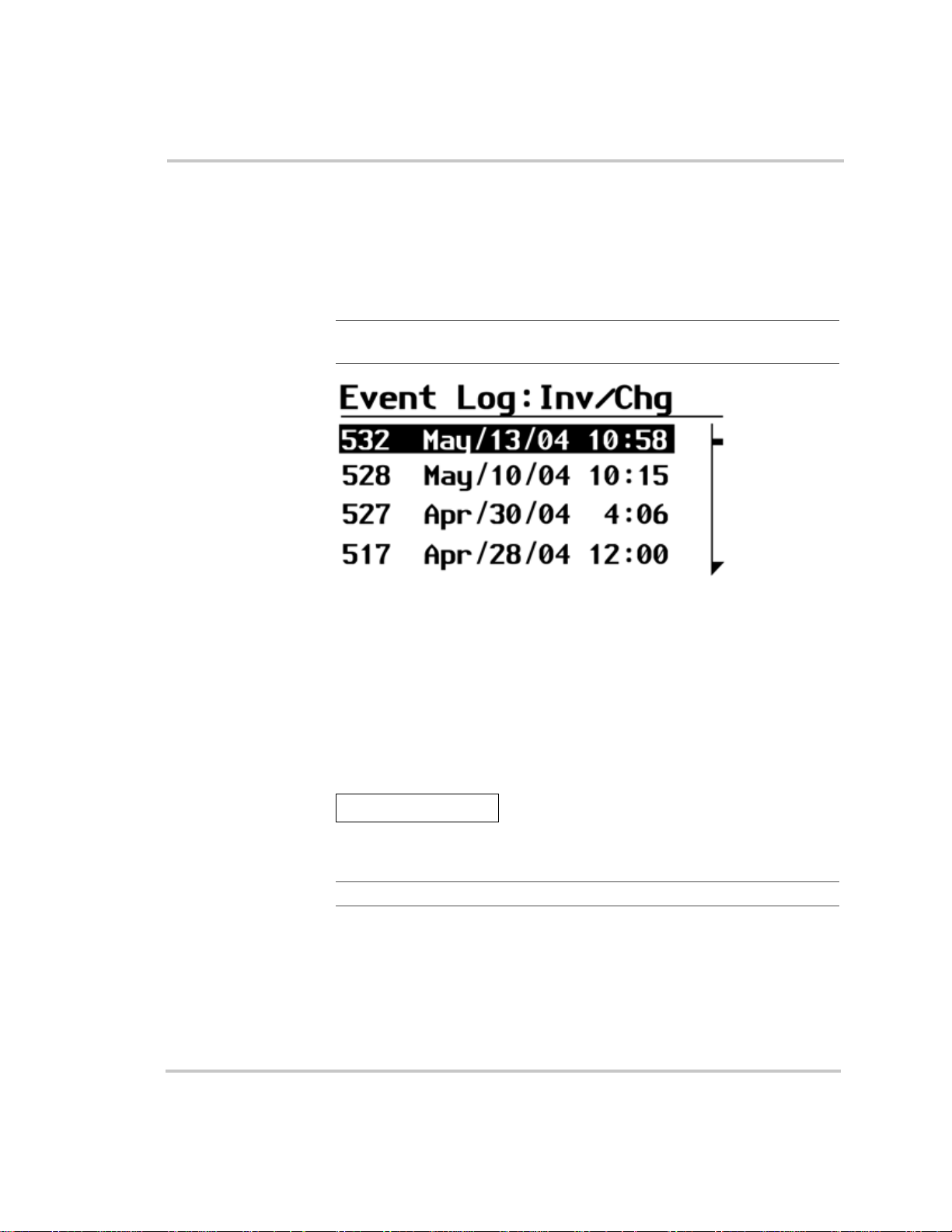
Configuration
View Event Log
Display setting The Event log, shown in Figure 3-14, displays the 10 most recent events.
Events can include:
• Changing the system mode
• Enabling or disabling the charger
Important:
additional menu items below the bottom edge of the display.
Figure 3-14
The Move Down arrow on the right of the menu indicates
Event Log
When to use The list provides useful information to a technical user about events on
the system, including an event ID, and the date and time of the event.
Restore Defaults
Configurable setting The Restore Default command restores the default settings for each
device.
Restore Defaults
When to use Adjust this setting when you wish to restore your settings to defaults.
Important:
Restoring to defaults will overwrite all of the stored values.
When you select Restore Defaults, a warning message appears, as shown
in Figure 3-15:
3–28 975-0170-01-01
Page 79
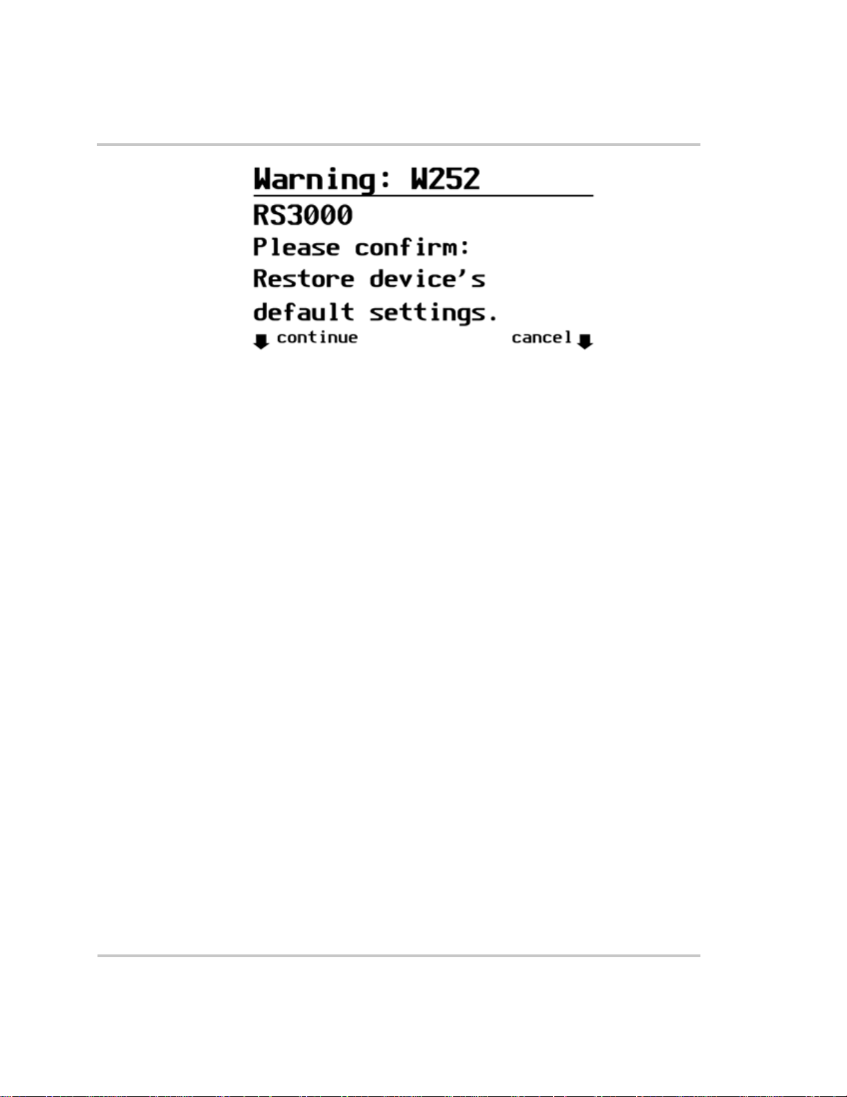
Configuration
Figure 3-15
Restore Defaults Warning
If you select continue, your settings will be restored to default.
If you select cancel, your existing settings will be retained and the Device
Info menu appears.
975-0170-01-01 3–29
Page 80

3–30
Page 81

4
Troubleshooting
WARNING: Electrical shock and fire hazard
Do not disassemble the RS3000. It does not contain any user serviceable parts.
Attempting to service the unit yourself could result in electrical shock or fire.
The RS3000 is designed for high reliability of operation and
has a number of protection features to provide trouble free
operation. If, however, you have any problems operating your
inverter/charger read this troubleshooting chapter.
If you cannot resolve the problem, record the necessary
information on the form, “Information About Your System”
on page WA–4. This information will help your dealer or
Xantrex Customer Service to assist you better when you
contact them.
Page 82

Troubleshooting
Faults and Warnings
When a fault or warning message appears, you can acknowledge the
message to clear the screen. To acknowledge a fault or warning message,
press the Enter button on the System Control Panel. This action does not
clear the fault or warning condition, so you should consult Table 4-3 and
Table 4-4 for suggested actions after you have acknowledged the
message. Refer to the System Control Panel Owner’s Guide for more
information on faults and warnings.
Fault Types
There are three types of fault messages: automatic faults, manual faults,
and escalating automatic faults. Table 4-1 describes how they differ in
their behavior and how you can respond to them when they appear on the
System Control Panel.
Table 4-1
Fault type Behavior
Automatic faults Clear automatically if the fault condition that
Manual faults Require you to clear them by:
Escalating automatic
faults
Faults Types and Behaviors
generated the message goes away. You can also
acknowledge automatic faults without waiting for
them to clear automatically.
• selectin g Clear Faults on th e RS3000 or on the
device that generated the fault (if the fault
condition still exists, the fault message
reappears)
• correctin g the condition that caused the fault
Clear automatically if the fault condition goes away,
just like an automatic fault.
However, if an escalating automatic fault occurs
several times within a defined time period, the
escalating automatic fault becomes a manual fault,
requiring user intervention. For example, if three
faults occur in one minute, it will no longer clear
itself but becomes a manual fault. Then you must
identify the problem, correct the fault condition, and
clear the fault or reset the device.
4–2 975-0170-01-01
Page 83

Warning Types
Troubleshooting
There are two types of warnings: automatic and manual. When the
RS3000 detects a warning condition, it displays a warning message on the
System Control Panel.
Table 4-2 describes how they differ in their behavior and in how you can
respond to them when they appear on the System Control Panel.
Table 4-2
Warning type Behavior
Automatic warning Clear automatically if the fault condition that
Manual warning Require you to acknowledge them before you can
Warning Types and Behavior
generated the message goes away. You can also
acknowledge automatic warnings without waiting
for them to clear automatically.
proceed with configuring or operating the RS3000.
Manual warnings are usually in the form of a
Yes/No question that you may acknowledge by
pressing the Enter button on the System Control
Panel for Yes and the Exit button for No.
Refer to the System Control Panel Owner’s Guide
for more information.
975-0170-01-01 4–3
Page 84

Troubleshooting
Troubleshooting Reference
This chapter provides you with troubleshooting tips to identify and solve
most problems that can occur with the RS3000.
This chapter is divided into the following four sections:
Section Page Number
General Troubleshooting Guidelines See page 4–5.
Warni ng Messag es See page 4–7.
Fault Messages See page 4–10.
Inverter Applications (Loads) See page 4–16.
4–4 975-0170-01-01
Page 85

General Troubleshooting Guidelines
This section will help you narrow down the source of any problem you
may encounter. Please read the following troubleshooting steps:
1. Check for a Warning or Fault message on the System Control Panel.
See “Warning Messages” on page 4–7 and “Fault Messages” on
page 4–10 for descriptions of these messages and the specific actions
to take. If a message is displayed, record it before doing anything
further.
2. As soon as possible, record on the form, “Information About Your
System” on page WA–4, the conditions at the time the problem
occurred. These details should include the following as well as any
other information asked for on page page WA–4:
• Loads the RS3000 was running or attempting to run
• Battery condition at the time of failure (voltage, state of charge,
for example), if known
• Recent sequence of events (for example, charging had just
finished, we disconnected shore power as were preparing to leave
the RV park, but the inverter didn’t come on)
• Any known unusual AC input factors such as low voltage or
unstable generator output
• Extreme conditions which may have existed at the time
(temperature, vibrations, moisture, for example).
3. Attempt the solution indicated in Table 4-3 or Table 4-4.
Troubleshooting
4. If your RS3000 or System Control Panel is not displaying a Fault
light, check the following list to make sure that the present state of the
installation allows proper operation of the unit:
❐ Is the inverter/charger located in a clean, dry, adequately ventilated
place?
❐ Have the AC input breakers opened? If so, your pass through load
may have exceeded the rating of one or more of the input breakers.
❐ Are the battery ca bles adequately sized and short enough?
❐ Is the battery in good condition and are all DC connections tight?
❐ Are the AC input and output connections and wiring in good
condition?
❐ Are the configuration settings correct for your particular installation?
❐ Are the display panel and the communications cable properly
connected and undamaged?
975-0170-01-01 4–5
Page 86

Troubleshooting
❐ Is the battery temperature sensor and its cable properly connected and
undamaged?
5. Contact Xantrex Customer Service for further assistance. Please be
prepared to describe details of your system installation and provide
the model and serial number of the unit. See “Contact Information”
on page v for contact information.
4–6 975-0170-01-01
Page 87

Warning Messages
Warning messages appear on the System Control Panel to alert you to an
impending system change. You can retrieve and view the last ten warning
messages using the control panel. The warnings have been recorded with
a time stamp to let you know the date and time that the warning appeared.
See “Warning Types” on page 4–3 for an explanation of automatic and
manual warnings.
You can view the most recent fault messages of the RS3000 (up to 20) by
selecting Fault Log from the Device Info menu in the RS3000 Advanced
Menu.
If several warning messages occur before you can acknowledge or clear
them, they are displayed together on a warning list. This list contains
messages from every Xanbus-enabled device, not just the RS3000. You
can select a message and view its details from warning list.
To view a message from a warning list:
1. On the list, use the up arrow or down arrow button to highlight the
message you want to view.
2. Press Enter.
The complete message appears.
After viewing the message, you can return to the warning list by pressing
Exit or continue to the menu for the device that caused the fault by
pressing Enter. Each time you return to the list after viewing a complete
message, the viewed message is removed from the list.
Troubleshooting
If you have left the warning list, you can view them at any time from the
System Settings menu.
To view a fault list:
1. On the Select Device menu, highlight System and press Enter.
2. On the System Settings menu, highlight View Warning List.
3. Press Enter.
975-0170-01-01 4–7
Page 88

Troubleshooting
Table 4-3 provides a detailed description of the warning messages and
solutions.
Table 4-3
Warning
Number Message
W0 FET1 over-temp.
W1 FET2 over-temp.
W2 Bulk cap. over-temp.
W3 Transf’r over-temp.
W4 Battery over-temp.
Warning Messages
Check airflow
around it.
Check airflow
around it.
Check airflow
around it.
Check airflow
around it.
Check battery
settings.
Warning
Type Cause Solution
Automatic FET1 Over
Temperature Warning
Automatic FET2 Over
Temperature Warning
Automatic DC Bulk Capacitor
Over Temperature
Warning
Automatic Transformer Over
Temperature Warning
Automatic Battery Over
Temperature Warning
Ensure adequate ventilation
around the RS3000. Reduce the
AC loads.
Ensure adequate ventilation
around the RS3000. Reduce the
AC loads.
Ensure adequate ventilation
around the RS3000. Reduce the
AC loads.
Ensure adequate ventilation
around the RS3000. Reduce the
AC loads.
Check battery voltage and
battery cable connections. Stop
charging, if necessary. Check
for excessive ambient
temperature and adequate
ventilation in the battery
compartment
W5 Over-temperature.
Check airflow
around it.
W6 Too many AC loads.
Turn some off.
W7 Yo u hav e e nabled
system restart after
faults.
W8 Yo u hav e e nabled
battery equalization.
See manual.
4–8 975-0170-01-01
Automatic Ambient Over
Temperature Warning
Automatic AC Overload Warning
(AC OUTPUT)
Automatic Auto Restart After
Fault Feature Enabled.
(This parameter is not
accessible through the
System Control Panel.
In the future, this
feature may be
configurable with
advanced panels.)
Automatic Equalization Enabled
Warning
Ensure adequate ventilation
around the RS3000. Reduce
charge rate or AC load.
Turn off some AC loads.
If in invert mode, the unit may
start up unexpectedly.
Make sure voltage sensitive
loads are disconnected from
batteries.
Page 89

Table 4-3
Troubleshooting
Warning Messages
Warning
Number Message
W9 Battery temp sensor
not detected. Check
connections.
W10 Battery temp sensor
failure.
W11 Batt voltage too high.
Check DC wiring to
inverter/charger.
W12 Battery voltage is
getting low.
Recharge battery.
W13 Line 1 AC voltage
too high. System may
shut down
W14 Line 1 AC voltage
too low. System may
shut down.
W15 Line 2 AC voltage
too high. System may
shut down.
Warning
Type Cause Solution
Automatic Battery Temperature
Sensor Not Present
Automatic Battery Temperature
Sensor Shorted
Automatic DC Over Voltage
Warning
Automatic DC Under Voltage
Warning
Automatic AC Over Voltage
Warning (AC Line 1
input)
Automatic AC Under Voltage
Warning (AC Line 1
input)
Automatic AC Over Voltage
Warning (AC Line 2
input)
Install a battery temperature
sensor (BTS). This warning
will continue to display as long
as no BTS is connected.
Replace battery temperature
sensor.
Turn off or check additional
charging sources to batteries.
Check battery cables.
Recharge batteries and check
battery cables from inverter to
batteries for loose connections.
Check AC input voltage.
Check high AC input voltage
setting.
Check AC input voltage.
Check low AC input voltage
setting.
Check AC input voltage.
Check high AC input voltage
setting.
W16 Line 2 AC voltage
too low. System may
shut down.
W18 Cannot Equalize Manual Cannot equalize Wrong battery type. Change
W19 Equalization
terminated
abnormally
W500 Lost network
connection
W501 Inv/Chg is trying to
fix a memory
problem
975-0170-01-01 4–9
Automatic AC Under Voltage
Warning (AC Line 2
input)
Manual Equalization
terminated abnormally
Automatic Lost network
connection
Manual Non-volatile memory
warning
Check AC input voltage.
Check low AC input voltage
setting.
battery type only if the battery
type setting is not the same as
actual battery type. Cannot
equalize a gel or AGM battery.
Investigate cause of problem.
Check network cables or
terminators.
Normal operation may return
or may go to fault. Push Reset
button if normal operation does
not resume.
Page 90

Troubleshooting
Fault Messages
When the RS3000 detects a fault condition, the fault is displayed on the
System Control Panel and also is indicated by the illuminated red Fault
light on the RS3000 front panel. A fault affects the operation of the unit.
See “Fault Types” on page 4–2 for an explanation of the different fault
types.
You can view the 20 most recent fault messages of the RS3000 by
selecting Fault Log from the Device Info menu in the RS3000 Advanced
Menu.
If several faults occur before you can acknowledge or clear them, they are
displayed together on a warning list. This list contains messages from
every Xanbus-enabled device, not just the RS3000. You can select a
message and view its details from the fault list.
To view a message from a fault list:
1. On the list, use the up arrow or down arrow button to highlight the
message you want to view.
2. Press Enter.
The complete message appears.
After viewing the message, you can return to the fault list by pressing Exit
or continue to the menu for the device that caused the fault by pressing
Enter. Each time you return to the list after viewing a complete message,
the viewed message is removed from the list.
If you have left the fault list, you can view them at any time from the
System Settings menu.
To view a fault list:
1. On the Select Device menu, highlight System and press Enter.
2. On the System Settings menu, highlight View Fault List.
3. Press Enter.
4–10 975-0170-01-01
Page 91

Troubleshooting
Table 4-4 provides a detailed description of the fault messages and
solutions. If you are unable to resolve the problem after referring to this
table, contact your dealer or Customer Service.
Table 4-4
Fault
Number Message
F0 Unit is too hot and
F2 Unit is too hot and
F3 Unit is too hot and
F4 Battery over-temp.
Fault Messages
has shut down. See
guide.
has shut down. See
guide.
has shut down. See
guide.
Inv/Chg has shut
down. See guide.
Fault
Type Cause Solution
Automatic FET1 Over
T emperature Shutdown
Automatic FET2 Over
T emperature Shutdown
Automatic Transformer Over
T emperature Shutdown
Automatic Battery Over
T emperature Shutdown
Clear the fault and attempt
restart. Ensure adequate
ventilation around the RS3000.
Reduce AC loads.
Clear the fault and attempt
restart. Ensure adequate
ventilation around the RS3000.
Reduce AC loads.
Clear the fault and attempt
restart. Ensure adequate
ventilation around the RS3000.
Reduce AC loads.
Clear the fault and attempt
restart. Stop charging, check
battery voltage and
temperature. Check for
excessive ambient temperature
and adequate ventilation in the
battery compartment.
F5 is too hot and has
shut down. See
guide.
F6 Too many AC loads.
Turn some off, clear
fault, try again.
975-0170-01-01 4–11
Automatic Ambient Over
T emperature Shutdown
Escalating
Auto Fault.
Must occur
3 times in
30 seconds
before
becoming
a manual
fault.
AC Overload
Shutdown (AC
OUTPUT)
Clear the fault and attempt
restart. Ensure adequate
ventilation around RS3000.
Reduce AC loads.
Clear the fault and attempt
restart. Reduce AC loads.
Check that AC input wiring is
not connected to the AC ouput.
Page 92

Troubleshooting
Table 4-4
Fault
Number Message
F7 Too many AC loads.
F8 Unit has lost input
F9 Battery voltage is too
Fault Messages
Turn some off, clear
fault, try again.
neutral connection.
See guide.
high. See guide.
Fault
Type Cause Solution
Escalating
Auto Fault.
Must occur
3 times in
30 seconds
before
becoming
a manual
fault.
Manual Neutral loss shutdown Clear the fault and attempt
Automatic DC Over Voltage
AC Overload (PEAK
CURRENT) Shutdown
(AC OUTPUT)
Shutdown
Clear the fault and attempt
restart. Reduce AC loads.
Check that AC input wiring is
not connected to the AC ouput.
restart. Check AC input wiring
for presence of a proper neutral
connection and ground
connection. Check the AC
input source to make sure the
neutral is bonded to ground.
Clear the fault and attempt
restart. Ensure battery voltage
is 10–16 VDC at RS3000
terminals. Check all other
charging source outputs,
battery cables.
F10 Battery is too low,
can’t invert.
Recharge battery.
F11 Battery is too low,
can’t invert.
Recharge battery.
F12 Input AC too high.
Check source, clear
fault, try again.
F13 Input AC too low.
Check source, clear
fault, try again.
4–12 975-0170-01-01
Automatic DC Under Voltage
Shutdown (Immediate)
occurs if DC voltage is
below 8 volts DC
Automatic DC Under Voltage
Shutdown occurs if
DC voltage is below
10 volts DC.
Automatic AC Over Voltage
Shutdown (AC Line 1
input)
Automatic AC Under Voltage
Shutdown (AC Line 1
input)
Clear the fault and attempt
restart. Recharge batteries.
Check battery cable
connections.
Clear the fault and attempt
restart. Recharge batteries.
Check battery cable
connections.
Clear the fault and attempt
restart. Check AC input
voltage. Check and adjust AC
input high voltage settings.
Clear the fault and attempt
restart. Check AC input
voltage. Check and adjust AC
input low voltage setting.
Page 93

Table 4-4
Troubleshooting
Fault Messages
Fault
Number Message
F14 Input AC too high.
Check source, clear
fault, try again.
F15 Input AC too low.
Check source, clear
fault, try again.
F16 AC input frequency
problem. Check gen
for overspeed.
F17 AC input frequency
problem. Check gen
for underspeed.
F18 AC input frequency
problem. Check gen
for overspeed.
Fault
Type Cause Solution
Automatic AC Over Voltage
Shutdown (AC Line 2
input)
Automatic AC Under Voltage
Shutdown (AC Line 2
input)
Automatic AC Over Frequency
Shutdown (AC Line 1
input)
Automatic AC Under Frequency
Shutdown (AC Line 1
input)
Automatic AC Over Frequency
Shutdown (AC Line 2
input)
Clear the fault and attempt
restart. Check AC input
voltage. Check and adjust AC
input high voltage settings.
Clear the fault and attempt
restart. Check AC input
voltage. Check and adjust AC
input low voltage setting.
Clear the fault and attempt
restart. Check AC input
frequency. Check and adjust
AC input high frequency
setting.
Clear the fault and attempt
restart. Check AC input
frequency. Check and adjust
AC input low frequency
setting.
Clear the fault and attempt
restart. Check AC input
frequency. Check and adjust
AC input high frequency
setting.
F19 AC input frequency
problem. Check gen
for underspeed.
F23 Inverter/Charger
internal failure.
Service required.
975-0170-01-01 4–13
Automatic AC Under Frequency
Shutdown (AC Line 2
input)
Escalating
Auto Fault.
Must occur
3 times in
30 seconds
before
becoming
a manual
fault.
AC Over Voltage
Shutdown (Inverter
AC output)
Clear the fault and attempt
restart. Check AC input
frequency. Check and adjust
AC input low frequency
setting.
Service required.
Page 94

Troubleshooting
Table 4-4
Fault
Number Message
F24 Inverter/Charger
F25 Inverter/Charger
F26 Inverter/Charger
Fault Messages
internal failure.
Service required.
internal failure.
Service required.
internal failure.
Service required.
Fault
Type Cause Solution
Escalating
Auto Fault.
Must occur
3 times in
60 seconds
before
becoming
a manual
fault.
Escalating
Auto Fault.
Must occur
3 times in
30 seconds
before
becoming
a manual
fault.
Escalating
Auto Fault.
Must occur
3 times in
30 seconds
before
becoming
a manual
fault.
AC Under Voltage
Shutdown (Inverter
AC output)
Auxiliary Power
Supply Over Voltage
Shutdown
Auxiliary Power
Supply Under Voltage
Shutdown
Service required.
Service required.
Service required.
F29 AC Backfeed fault:
Service immediately.
F30 Unit is too cold and
has shut down. See
guide.
F40 Internal fault. If fault
persists, call
Customer Support.
F41 Internal fault. Reset.
If fault persists, call
Customer Support.
4–14 975-0170-01-01
Manual AC Backfeed
Shutdown
Manual Battery Under
Temperature Fault
Manual No IPC
communication
Manual Dead battery charger
timeout
Service required.
Clear the fault and attempt one
restart. Try restart again when
ambient temperature is warmer
or gently warm the battery.
Service required.
Try restarting dead battery
charging once. Then check the
condition of the battery and
replace if necessary.
Page 95

Table 4-4
Troubleshooting
Fault Messages
Fault
Number Message
F500 Silicon Serial ID
Failure
F502 Watchdog reset error Manual Watchdog reset error Service required.
F505 Controller fault Manual Controller fault Service required.
F506 Wrong fault
identifier
F507 Wrong identifier Manual Wrong identifier Service required.
F508 Invalid interrupt Manual Invalid interrupt Service required.
Fault
Type Cause Solution
Manual Silicon Serial ID
Failure
Manual Wrong fault identifier Service required.
Service required.
975-0170-01-01 4–15
Page 96

Troubleshooting
Inverter Applications
The RS3000 performs differently depending on the AC loads connected
to it. If you are having problems with any of your loads, read this section.
Resistive Loads
These are the loads that the inverter finds the simplest and most efficient
to drive. Voltage and current are in phase, which means they are in step
with one another. Resistive loads usually generate heat in order to
accomplish their tasks. Toasters, coffee pots, and incandescent lights are
typical resistive loads. It is usually impractical to run larger resistive
loads—such as electric stove and water heaters—from an inverter due to
their high current requirements. Even though the inverter may be able to
accommodate the load, the size of battery bank required would be
impractical if the load is to be run for long periods.
Motor Loads
Induction motors (motors without brushes) require two to six times their
running current on start up. The most demanding are those that start under
load (for example, compressors and pumps). Of the capacitor start motors
(typical in drill presses, band saws for example), the largest you can
expect to run is 1 hp. Universal motors are generally easier to start. Since
motor characteristics vary, only testing will determine whether a specific
load can be started and how long it can be run.
If a motor fails to start within a few seconds or loses power after running
for a time, it should be turned off. When the inverter attempts to start a
load that is greater than it can handle, the inverter will turn itself off after
a few seconds.
Problem Loads
Very Small Loads
If the power consumed by a device is less than the threshold of the Load
Sense mode circuitry, and load sense is enabled, the inverter will not run.
Most likely the solution will be to disable the Load Sense mode feature or
lower the sense threshold. Refer to Xantrex Tech Note TN3 (979-000301-01) for more information.
4–16 975-0170-01-01
Page 97

Fluorescent Lights & Power Supplies
Some devices cannot be detected when scanned by Load Sense circuitry.
Small fluorescent lights are the most common example. Some computers
and sophisticated electronics have power supplies that do not present a
load until line voltage is available. When this occurs, each unit waits for
the other to begin. To drive these loads, either a small companion load
like a light bulb rated for more than the load sense setting must be used to
bring the inverter out of its search mode, or the inverter may be
programmed to remain on by disabling the Load Sense featu r e. (See
“Load Sense” on page 3–19.)
Clocks
You may notice that your clocks may not be accurate. Some of the clocks
on your appliances may reset when the inverter/charger is in load sense
mode.
Searching
When the inverter is in Load Sense (search) mode, it may fail to start
some loads even though the rated wattage on the load is more than the
load sense setting. Apply an additional load (companion load) to make the
inverter exit Load Sense mode.
Troubleshooting
975-0170-01-01 4–17
Page 98

4–18
Page 99

A
Specifications
Appendix A, “Specifications” contains the electrical and
physical specifications for the RS3000 Sine Wave Inverter/
Charger.
All specifications are subject to change without notice.
Page 100

Specifications
Inverter Specifications
All inverter specifications are at nominal conditions: ambient temperature
°F (25 °C), 3000 watt resistive load, 12 volts DC inverting on the
of 77
RS3000, 120 volts AC, unless otherwise specified.
Table A-1
Inverter Specifications
Output wave form Sine wave
Total harmonic voltage distortion <3%
Output power up to 3000 W/3000 VA
Surge rating 7500 W/7500 VA for 5 seconds
AC output voltage 120 VAC ± 5%
Input DC voltage rating 12 VDC nominal, 10 to 16 VDC
AC output frequency 60.0 ± 0.05 Hz
Power factor (lag or lead) 0 to 1.0
Peak efficiency >89%
Efficiency at 3000W >85%
No load power draw Load sense On <14W
Load sense Off <60W
DC low voltage shutdown 10 volts
DC over voltage shutdown 16 volts
A–2 975-0170-01-01
 Loading...