

Xantrex GT100-208, GT100-480, GT100-208-NG, GT100-208-PG, GT100-480-NG Operation And Maintenance Manual
...Page 1
Xantrex™ GT100
Grid-Tied Photovoltaic
Inverter
GT100-208
GT100-480
Operation and Maintenance Manual
Page 2

Page 3

Xantrex™ GT100 Grid-Tied
Photovoltaic Inverter
Operation and Maintenance Manual
Page 4

About Xantrex
Xantrex Technology Inc. is a world-leading supplier of advanced power electronics and controls with products
ranging from small mobile units to utility-scale systems for wind, solar, batteries, fuel cells, microturbines, and
backup power applications in both grid-connected and stand-alone systems. Xantrex products include inverters,
battery chargers, programmable power supplies, and variable speed drives that convert, supply, control, clean, and
distribute electrical power.
Trademarks
Xantrex and Smart choice for power are trademarks of Xantrex International, registered in the United States and
other countries.
Notice of Copyright
Copyright © September 2008 Xantrex Technology Inc. No part of this document may be reproduced in any form or
disclosed to third parties without the express written consent of:
Xantrex Technology Inc.
161-G South Vasco Road
Livermore, California
USA 94551
Exclusion for Documentation
UNLESS SPECIFICALLY AGREED TO IN WRITING, XANTREX TECHNOLOGY INC. (“XANTREX™”)
(
A) MAKES NO WARRANTY AS TO THE ACCURACY, SUFFICIENCY OR SUITABILITY OF ANY TECHNICAL OR OTHER
INFORMATION PROVIDED IN ITS MANUALS OR OTHER DOCUMENTATION.
(
B) ASSUMES NO RESPONSIBILITY OR LIABILITY FOR LOSSES, DAMAGES, COSTS OR EXPENSES, WHETHER SPECIAL,
DIRECT, INDIRECT, CONSEQUENTIAL OR INCIDENTAL, WHICH MIGHT ARISE OUT OF THE USE OF SUCH INFORMATION.
T
HE USE OF ANY SUCH INFORMATION WILL BE ENTIRELY AT THE USER’S RISK; AND
(C) REMINDS YOU THAT IF THIS MANUAL IS IN ANY LANGUAGE OTHER THAN ENGLISH, ALTHOUGH STEPS HAVE BEEN
TAKEN TO MAINTAIN THE ACCURACY OF THE TRANSLATION, THE ACCURACY CANNOT BE GUARANTEED. APPROVED
XANTREX CONTENT IS CONTAINED WITH THE ENGLISH LANGUAGE VERSION WHICH IS POSTED AT
WWW.XANTREX.COM.
Date and Revision
September 2008 Revision B
Manual Part Number
153378
Contact Information
Telephone: 1 800 670 0707 (toll free North America)
Fax: 1 800 994 7828 (toll free North America)
Email: customerservice@xantrex.com
Web: www.xantrex.com
1 408 987 6030 (direct)
Page 5

About This Manual
Purpose
The purpose of this Operation and Maintenance Manual is to provide explanations
and procedures for operating, maintaining, and troubleshooting the GT100 GridTied Photovoltaic Inverter. Installation instructions are available in the GT100
Grid-Tied Photovoltaic Inverter Planning and Installation Manual (Part
#:153379).
Scope
This Manual provides safety guidelines and information about operating and
troubleshooting the unit.
Audience
This Manual is intended for anyone who needs to operate the GT100 Grid-Tied
Photovoltaic Inverter. Operators must be familiar with all the safety regulations
pertaining to operating high-voltage equipment as dictated by local code.
Operators must also have a complete understanding of this equipment’s features
and functions. Do not to use this product unless it has been installed by a qualified
installer in accordance with the GT100 Grid-Tied Photovoltaic Inverter Planning
and Installation Manual (Part #:153379).
Organization
This Manual is organized into five chapters and two appendices.
Chapter 1, “Introduction” contains information about the features and functions of
the GT100 Grid-Tied Photovoltaic Inverter.
Chapter 2, “Operation” contains information on the basic operation of the GT100
Grid-Tied Photovoltaic Inverter.
Chapter 3, “Commissioning” contains information on safely commissioning the
GT100 Grid-Tied Photovoltaic Inverter.
Chapter 4, “Troubleshooting” contains information and procedures for
troubleshooting the GT100 Grid-Tied Photovoltaic Inverter. It provides
descriptions of common situations and errors that may occur and provides
possible solutions for resolving fault conditions. It also provides instructions for
clearing faults manually, if required.
Chapter 5, “Preventative Maintenance” contains information and procedures for
performing preventative maintenance on the GT100 Grid-Tied Photovoltaic
Inverter.
Appendix A provides the environmental and electrical specifications for the
GT100 Grid-Tied Photovoltaic Inverter.
Appendix B contains the Commissioning Test Record for the GT100 Grid-Tied
Photovoltaic Inverter.
153378 iii
Page 6
About This Manual
Conventions Used
The following conventions are used in this guide.
WARNING
Warnings identify conditions or practices that could result in personal injury or loss of life.
CAUTION
Cautions identify conditions or practices that could result in damage to the unit or
other equipment.
GT100 Models
Important:
serious as a caution or warning.
This Operation and Maintenance Manual contains information for four models of
the GT100 Grid-Tied Photovoltaic Inverter.
Two of the models are designed to operate with a 208 Vac utility input; one
configured for a negative grounded PV array (GT100-208-NG), and the other
configured for a positive grounded PV array (GT100-208-PG).
•The model GT100-208-NG Grid-Tied Photovoltaic Inverter (208 Vac input,
negative grounded) will be referred to as the GT100-208-NG when it is being
referenced individually.
•The model GT100-208-PG Grid-Tied Photovoltaic Inverter (208 Vac input,
positive grounded) will be referred to as the GT100-208-PG when it is being
referenced individually.
Additionally, two of the models are designed to operate with a 480 Vac utility
input; one configured for a negative grounded PV array (GT100-480-NG), and the
other configured for a positive grounded PV array (GT100-480-PG).
•The model GT100-480-NG Grid-Tied Photovoltaic Inverter (480 Vac input,
negative grounded) will be referred to as the GT100-480-NG when it is being
referenced individually.
•The model GT100-480-PG Grid-Tied Photovoltaic Inverter (480 Vac input,
positive grounded) will be referred to as the GT100-480-PG when it is being
referenced individually.
When all models are being referenced together, they will be referred to as
the GT100.
These notes describe things which are important for you to know, but not as
iv 153378
Page 7

Abbreviations and Acronyms
ANSI American National Standards Institute
CCU2 Converter Control Unit 2
CFM Cubic Feet per Minute
CW Clockwise
DSP Digital Signal Processor
GUI Graphical User Interface
IEEE Institute of Electrical and Electronics Engineers
IGBT Insulated Gate Bipolar Transistor
kcmil 1000 circular mils
LM Liter per Minute
NFPA National Fire Protection Association
PSL Phase-Shift Loop
About This Manual
PV Photovoltaic
UFCU Universal Frontpanel Control Unit
VFD Vacuum Fluorescent Display
Related Information
You can find more information about Xantrex Technology Inc. as well as its
products and services at www.xantrex.com.
153378 v
Page 8

vi
Page 9
Important Safety Instructions
SAVE THESE INSTRUCTIONS - DO NOT DISCARD
This manual contains important safety instructions for the GT100 Grid-Tied
Photovoltaic Inverter that must be followed during installation and maintenance
procedures.
WARNING: Shock Hazard
Read and keep this Operation and Maintenance Manual for future reference.
Before operating and maintaining the GT100, read all instructions, cautionary markings,
and all other appropriate sections of this manual. Failure to adhere to these warnings could
result in severe shock or possible death. Exercise extreme caution at all times to prevent
accidents.
WARNING: Shock Hazard
• The GT100 enclosure contains exposed high voltage conductors.
• The enclosure doors should remain closed with the latches tightened, except during
installation, maintenance or testing.
• These instructions are for use by qualified personnel who meet all local and
governmental code requirements for licensing and training for the installation of
Electrical Power Systems with AC and DC voltage to 600 volts.
• To reduce the risk of electric shock, do not perform any servicing other than that
specified in the installation instructions unless you are qualified to do so.
• Do not open the cabinet doors if extreme moisture is present (rain or heavy dew).
WARNING: Lethal Voltage
In order to remove all sources of voltage from the GT100, the incoming power must be deenergized at the source. This may be done at the main utility circuit breaker, the PV array
disconnect, and by opening the AC Disconnect and the DC Disconnect Switch on the
GT100. Review the system configuration to determine all of the possible sources of
energy. In addition, allow five minutes for the DC bus capacitors to discharge after
removing power. Follow the “Lockout and Tag (De-energize/Isolation Procedure)”
procedure on page xii to de-energize the GT100.
WARNING: Shock hazard
If a ground fault has occurred, there may be potential between TB4 and GND. The
normally grounded pole may be energized and ungrounded.
153378 vii
Page 10
Safety
Risks
WARNING: Shock Hazard
The DC bus capacitors within the GT100 can still be energized for a maximum of five
minutes after being disconnected. Open doors only after the GT100 has been disabled (S3)
and the capacitor bank discharge time has expired. Verify that the capacitors are no longer
energized (DC voltage) including terminals TB3 and TB4.
WARNING: Explosion Hazard
The IGBT module may explode in the event of a major malfunction.The GT100 enclosure
doors should remain closed with the latches tightened, except during maintenance or
testing.
WARNING: Crush Hazard
The inverters have a specific balance point that correlates to their center of gravity and can
fall over. Be very careful when moving the GT100.
WARNING: Amputation Hazard
The inverters contain integrated ventilators including rotating ventilator wheels. Do not
place fingers in ventilator.
WARNING: Burn Hazard
Inverters contain components that become hot during normal operation. Do not touch.
CAUTION
The GT100 incorporates an air supply and exhaust air area, which must remain
unobstructed. The device can overheat and be destroyed if the installation instructions are
not adhered to.
CAUTION
Sensitive electronics inside the GT100 can be destroyed when touched and when
electrostatically charged. Discharge via earth potential before touching and wear
appropriate protective gear.
CAUTION
No connections or disconnections are to be made at the terminal strips or internal
connectors during operation. Turn the unit off before performing any terminal work; wait
five minutes for the capacitors to discharge and recheck to ensure internal components are
no longer energized.
viii 153378
Page 11

General Safety Precautions
1. When installing the GT100 use only components recommended or sold by
Xantrex. Doing otherwise may result in a risk of fire, electric shock, injury to
persons, and will void the warranty.
2. Do not attempt to operate the GT100 if it has been dropped, or received more
than cosmetic damage during transport or shipping. If the GT100 is damaged,
or suspected to be damaged, see the Warranty section of this manual.
3. To reduce the risk of electrical shock, lock-out and tag the GT100 before
attempting any maintenance, service, or cleaning.
Personal Safety
Follow these instructions to ensure your safety while working with the GT100.
Qualified Personnel
Only qualified personnel should perform the transportation, installation and initial
operation and maintenance of the GT100 in accordance with National Electrical
Code ANSI/NFPA 70, as well as all state and local code requirements. Follow all
national accident prevention regulations.
Safety
Safety Equipment
Qualified personnel, within the meaning of these basic safety regulations, will be
people who are familiar with the installation, assembly, start-up and operation of
the GT100 and have the appropriate qualifications with respect to their functions.
Authorized service personnel must be equipped with standard safety equipment
including the following:
• Safety glasses
• Ear protection
• Steel-toed safety boots
• Safety hard hats
• Padlocks and tags
• Appropriate meter to verify that the circuits are de-energized
(1000 Vac and DC rated, minimum)
Check local safety regulations for other requirements.
153378 ix
Page 12

Safety
Wiring Requirements
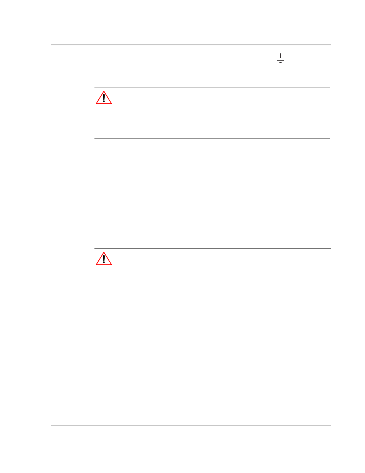
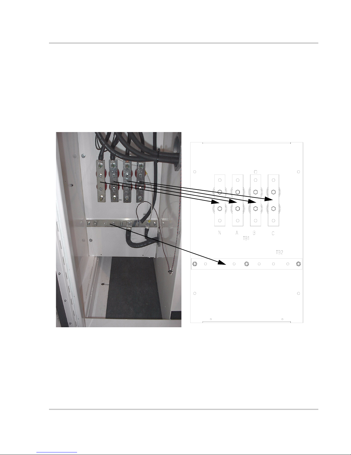
1. All wiring methods and materials shall be in accordance with the National
Electrical Code ANSI/NFPA 70, as well as all state and local code requirements.
• Use copper conductors with an insulation rating of 90°C.
• If installed, the optional Fused Combiner (GTFC) requires the use of copper
conductors with a maximum insulation rating of 75°C.
2. The GT100 has a three-phase, four-wire output.
3. The GT100 is interfaced with the AC utility grid at TB1 (TB1-A, TB1-B, TB1-C
and TB1-N), located in the lower left side of the enclosure. These terminals
require the use of a UL-approved crimp-on type ring terminal or a UL-approved
compression-type lug certified for use with the chosen interface cables. Keep
these cables together as much as possible and ensure that all cables pass through
the same knockout and conduit fittings, allowing any inductive currents to
cancel. For torque values, see Table A-5 on page A–5. See Figure 1-3 on page 5
for the location of these terminals.
4. The AC neutral terminals (H0 and X0), shall be left floating (not connected) on
both the utility and inverter sides of the isolation transformer.
See page xii for details.
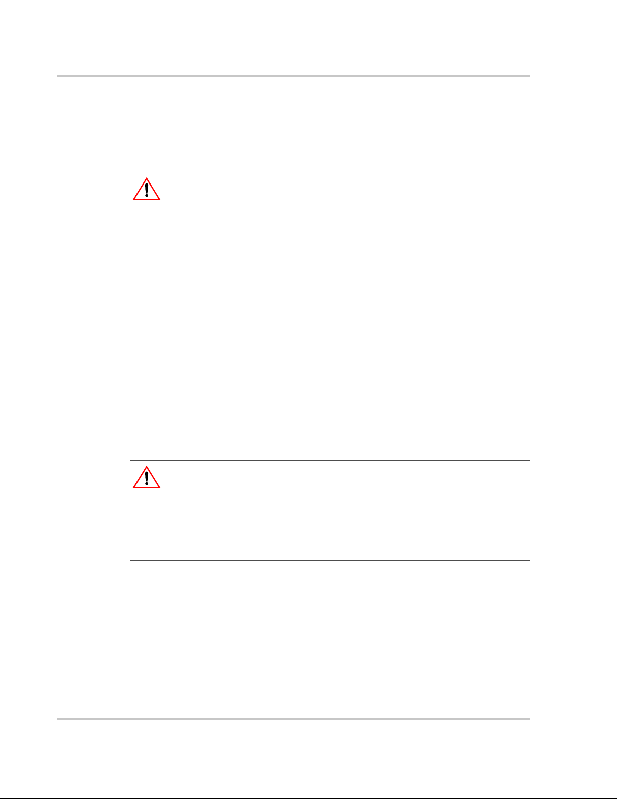
5. The GT100 is interfaced with the DC photovoltaic array at either the Fused
Combiner (GTFC) or TB3, as well as TB4 and TB5 (PV GND), located in the
lower right side of the enclosure. Do not connect the grounded power conductor
from the PV array directly to TB5 (PV GND); doing so will bypass the ground
fault detector and violate the NEC.
6. The TB3, TB4, and TB5 terminals require the use of a UL-approved crimp-on
type ring lug or a UL-approved compression-type lug certified for use with the
chosen interface cables. The Fused Combiner assembly includes box style
connectors for cable termination. Keep these cables together as much as possible
and ensure that all cables pass through the same knockout and conduit fittings,
allowing any inductive currents to cancel. For acceptable torque values for the
box style connectors and the TB3, TB4, and TB5 terminals, see Table A-6 and
Table A-7 on page A–5. See Figure 1-5 on page 1–8, Figure 1-6 on page 1–9,
Table 1-1 on page 1–8, and Table 1-2 on page 1–9 for the location and polarity of
these terminals.
7. This product is intended to be installed as part of a permanently grounded
electrical system as per the National Electrical Code ANSI/NFPA 70, as well as
all state and local code requirements. A copper clad earth grounding electrode
must be installed within 3 ft. (1 m) of the GT100 enclosure to ensure compliance
with FCC Part 15, Class A.. The AC ground bus bar (TB2), located in the lower
left side of the GT100 enclosure, must be used as the single point connection to
the earth grounding electrode for the inverter system.
x 153378
Page 13
8. The equipment grounds on the GT100 are marked with .
9. AC overcurrent protection for the utility interconnect (Grid-tie) must be
provided by the installers as part of the GT100 installation.
CAUTION: Fire Hazard
In accordance with the National Electrical Code, ANSI/NFPA 70, connect only to a circuit
provided with 400 amperes maximum branch circuit overcurrent protection for models
GT100-208-NG and GT100-208-PG, and only to a circuit provided with 200 amperes
maximum branch circuit overcurrent protection for models GT100-480-NG and GT100-480PG.
Inverter Isolation Transformer
The GT100 includes a custom, high-efficiency, isolation transformer. The utility
side windings of the isolation transformer are configured Wye and must match the
voltage at the utility inter-tie. The GT100 is a balanced, three-phase, currentsourcing inverter and only operates with the presence of a stable utility voltage.
The transformer is supplied with a neutral connection on both the Primary and
Secondary windings. Connection of these neutral terminals will affect the
operation of the GT100 and must be left floating or disconnected. Single-phase,
grounded loads which may be present between the transformer and utility, will
maintain their existing ground reference at the utility distribution transformer.
Safety
CAUTION: Equipment Damage
If the Isolation Transformer neutral (H0 and X0) terminals are tied to ground, they may
cause irreparable damage to the GT100. Check local regulations for their requirements
regarding the connection of these neutrals.
Operational Safety Procedures
Never work alone when servicing this equipment. A team of two is required until
the equipment is properly de-energized, locked-out and tagged, and verified deenergized with a meter.
Thoroughly inspect the equipment prior to energizing. Verify that no tools or
equipment have been inadvertently left behind.
153378 xi
Page 14
Safety
Lockout and Tag (De-energize/Isolation Procedure)
Safety requirements mandate that this equipment not be serviced while energized.
Power sources for the GT100 must be locked-out and tagged prior to servicing. A
padlock and tag should be installed on each energy source prior to servicing.
WARNING: Shock Hazard
Review the system schematic for the installation to verify that all available energy sources
are de-energized. DC bus voltage may also be present. Once all sources of input are
identified and isolated, allow five minutes for all capacitors within the main enclosure to
completely discharge before proceeding.
The GT100 can be energized from both the AC source and the DC source. To
ensure that the inverter is de-energized prior to servicing, lockout and tag the
GT100 using the following procedure.
1. Turn the GT100 main ON/OFF switch (S3) to the OFF position. This stops
the inverter from exporting power to the AC utility grid.
2. Open, lockout, and tag the incoming power at the utility main circuit breaker.
3. Open, lockout, and tag the AC Disconnect (CB1) on the left door of the
GT100. See Figure 1-8 on page 11 for the location of the AC Disconnect.
4. Open, lockout, and tag the incoming power at the PV array disconnect (if
installed.) If a PV array disconnect is not installed, see the WARNING below.
5. Open, lockout, and tag the DC Disconnect Switch (S1) on the right door of the
GT100. See Figure 1-8 on page 11 for the location of the DC
Disconnect Switch.
WARNING: Shock Hazard
Xantrex recommends the installation of PV array disconnect(s) to ensure personal safety
during GT100 maintenance. WITHOUT PV ARRAY DISCONNECT(S), ONCE THE
DC DISCONNECT SWITCH (S1) IS OPEN, THERE WILLSTILL BE DC
VOLTAGE on the DC terminals TB3, TB4 AND TB5 (PV GND). This voltage may be
as high as the open-circuit voltage of the PV Array and is limited to 600Vdc per NEC 690.
Use extreme care to avoid these terminals if no PV array disconnect is installed.
6. Using a confirmed, accurate meter, verify all power to the inverter is deenergized. A confirmed, accurate meter must be verified on a known voltage
before use. Ensure that all incoming energy sources are de-energized by
checking the following locations at all line-to-line and all line-to-ground
configurations.
• AC Utility Terminals: [TB1-A, TB1-B, TB1-C, TB1-N, and
TB2(GND BUS)]
See Figure i on page xiii for the location of these terminals.
• PV Terminals: [TB3, TB4, and TB5 (PV GND)]
See Figure ii on page xiii for the location of these terminals.
xii 153378
Page 15
Safety
N
A
B
TB1
C
TB2
Figure i
Figure ii
AC Utility Terminals
TB5
(PV GND)
DC Terminals
TB3 TB4
153378 xiii
Page 16

Safety
Interconnection Standards Compliance
The GT100 complies with FCC Part 15 Class A requirements.
The GT100 is designed to meet NEC Article 690 and UL1741-2005 Static
Inverters And Charge Controllers For Use In Photovoltaic Power Systems, which
includes testing for IEEE 1547.1-2005, IEEE 929-2000 and IEEE 519-2000.
Intended Use
The GT100 may only be used in connection with PV modules. It is not suitable for
any other application areas.
xiv 153378
Page 17

Contents
Important Safety Instructions
1
Introduction
Description of the GT100 - - - - - - - - - - - - - - - - - - - - - - - - - - - - - - - - - - - - - - - - - - - - - - - - - 1–2
Power Conversion System - - - - - - - - - - - - - - - - - - - - - - - - - - - - - - - - - - - - - - - - - - - - - - 1–2
Advanced Design Features - - - - - - - - - - - - - - - - - - - - - - - - - - - - - - - - - - - - - - - - - - - - - 1–2
Physical Characteristics - - - - - - - - - - - - - - - - - - - - - - - - - - - - - - - - - - - - - - - - - - - - - - - - - - 1–3
AC Interface - - - - - - - - - - - - - - - - - - - - - - - - - - - - - - - - - - - - - - - - - - - - - - - - - - - - - - - 1–5
AC Utility Terminals - - - - - - - - - - - - - - - - - - - - - - - - - - - - - - - - - - - - - - - - - - - - - - 1–5
Auxiliary Control Interface - - - - - - - - - - - - - - - - - - - - - - - - - - - - - - - - - - - - - - - - - - 1–6
Communications Circuit - - - - - - - - - - - - - - - - - - - - - - - - - - - - - - - - - - - - - - - - - - - - 1–6
Power Electronics - - - - - - - - - - - - - - - - - - - - - - - - - - - - - - - - - - - - - - - - - - - - - - - - - - - 1–7
Converter Control Unit (CCU2) - - - - - - - - - - - - - - - - - - - - - - - - - - - - - - - - - - - - - - - 1–7
Power Electronics Matrix - - - - - - - - - - - - - - - - - - - - - - - - - - - - - - - - - - - - - - - - - - - - 1–7
DC Interface - - - - - - - - - - - - - - - - - - - - - - - - - - - - - - - - - - - - - - - - - - - - - - - - - - - - - - - 1–8
DC Terminals - - - - - - - - - - - - - - - - - - - - - - - - - - - - - - - - - - - - - - - - - - - - - - - - - - - 1–8
Fused Combiner (Optional) - - - - - - - - - - - - - - - - - - - - - - - - - - - - - - - - - - - - - - - - - - 1–9
Circuit Diagram - - - - - - - - - - - - - - - - - - - - - - - - - - - - - - - - - - - - - - - - - - - - - - - - - - - - 1–10
Operator Interface Controls - - - - - - - - - - - - - - - - - - - - - - - - - - - - - - - - - - - - - - - - - - - - - - 1–11
On/Off Switch - - - - - - - - - - - - - - - - - - - - - - - - - - - - - - - - - - - - - - - - - - - - - - - - - - - - - 1–12
Emergency Stop (E-STOP) - - - - - - - - - - - - - - - - - - - - - - - - - - - - - - - - - - - - - - - - - - - - 1–12
Auxiliary Enable/Disable - - - - - - - - - - - - - - - - - - - - - - - - - - - - - - - - - - - - - - - - - - - - - 1–12
AC Disconnect and DC Disconnect Switches - - - - - - - - - - - - - - - - - - - - - - - - - - - - - - - - 1–13
Operation Features - - - - - - - - - - - - - - - - - - - - - - - - - - - - - - - - - - - - - - - - - - - - - - - - - - - - 1–14
Fixed Unity Power Factor Operation - - - - - - - - - - - - - - - - - - - - - - - - - - - - - - - - - - - - - - 1–14
Peak Power Tracking - - - - - - - - - - - - - - - - - - - - - - - - - - - - - - - - - - - - - - - - - - - - - - - - 1–14
Utility Voltage/Frequency Fault Automatic Reset - - - - - - - - - - - - - - - - - - - - - - - - - - - - - 1–15
Safety Features - - - - - - - - - - - - - - - - - - - - - - - - - - - - - - - - - - - - - - - - - - - - - - - - - - - - - - - 1–16
Anti-Island Protection - - - - - - - - - - - - - - - - - - - - - - - - - - - - - - - - - - - - - - - - - - - - - - - - 1–16
PV Ground Fault Detection - - - - - - - - - - - - - - - - - - - - - - - - - - - - - - - - - - - - - - - - - - - - 1–16
DC Over-voltage Detection - - - - - - - - - - - - - - - - - - - - - - - - - - - - - - - - - - - - - - - - - - - - 1–16
Communication Features and Methods - - - - - - - - - - - - - - - - - - - - - - - - - - - - - - - - - - - - - - - 1–17
System Status and Fault Reporting - - - - - - - - - - - - - - - - - - - - - - - - - - - - - - - - - - - - - - - 1–17
Data Logging - - - - - - - - - - - - - - - - - - - - - - - - - - - - - - - - - - - - - - - - - - - - - - - - - - - - - 1–19
Oscillography - - - - - - - - - - - - - - - - - - - - - - - - - - - - - - - - - - - - - - - - - - - - - - - - - - - - - 1–20
Optional Equipment - - - - - - - - - - - - - - - - - - - - - - - - - - - - - - - - - - - - - - - - - - - - - - - - - - - 1–21
Communication Modems - - - - - - - - - - - - - - - - - - - - - - - - - - - - - - - - - - - - - - - - - - - - - 1–21
PV Combiner - - - - - - - - - - - - - - - - - - - - - - - - - - - - - - - - - - - - - - - - - - - - - - - - - - - - - 1–21
- - - - - - - - - - - - - - - - - - - - - - - - - - - - - - - - - - - - - - - - - -vii
153378 xv
Page 18

2
Operation
Description of System Operation - - - - - - - - - - - - - - - - - - - - - - - - - - - - - - - - - - - - - - - - - - - - 2–2
Overview - - - - - - - - - - - - - - - - - - - - - - - - - - - - - - - - - - - - - - - - - - - - - - - - - - - - - - - - - 2–2
Faults - - - - - - - - - - - - - - - - - - - - - - - - - - - - - - - - - - - - - - - - - - - - - - - - - - - - - - - - - - - - 2–2
Operating States - - - - - - - - - - - - - - - - - - - - - - - - - - - - - - - - - - - - - - - - - - - - - - - - - - - - - - - 2–3
Shutdown - - - - - - - - - - - - - - - - - - - - - - - - - - - - - - - - - - - - - - - - - - - - - - - - - - - - - - - - - 2–4
Transition - - - - - - - - - - - - - - - - - - - - - - - - - - - - - - - - - - - - - - - - - - - - - - - - - - - - - - - - - 2–4
Power Tracking - - - - - - - - - - - - - - - - - - - - - - - - - - - - - - - - - - - - - - - - - - - - - - - - - - - - - 2–4
Automatic Sleep Test - - - - - - - - - - - - - - - - - - - - - - - - - - - - - - - - - - - - - - - - - - - - - - - - - 2–4
Manual Current - - - - - - - - - - - - - - - - - - - - - - - - - - - - - - - - - - - - - - - - - - - - - - - - - - - - - 2–4
Matrix Test - - - - - - - - - - - - - - - - - - - - - - - - - - - - - - - - - - - - - - - - - - - - - - - - - - - - - - - - 2–5
Fault - - - - - - - - - - - - - - - - - - - - - - - - - - - - - - - - - - - - - - - - - - - - - - - - - - - - - - - - - - - - 2–5
Operator Interface - - - - - - - - - - - - - - - - - - - - - - - - - - - - - - - - - - - - - - - - - - - - - - - - - - - - - - 2–7
UFCU Keypad Operation and VFD Display - - - - - - - - - - - - - - - - - - - - - - - - - - - - - - - - - - 2–7
VFD Display - Initialization Screen - - - - - - - - - - - - - - - - - - - - - - - - - - - - - - - - - - - - - - - 2–8
Standard Display - - - - - - - - - - - - - - - - - - - - - - - - - - - - - - - - - - - - - - - - - - - - - - - - - - - - 2–9
Menu Structure - - - - - - - - - - - - - - - - - - - - - - - - - - - - - - - - - - - - - - - - - - - - - - - - - - - - - 2–9
Read Menu - - - - - - - - - - - - - - - - - - - - - - - - - - - - - - - - - - - - - - - - - - - - - - - - - - - - 2–10
WRITE Menu - - - - - - - - - - - - - - - - - - - - - - - - - - - - - - - - - - - - - - - - - - - - - - - - - - 2–16
Commanding Goal State Changes - - - - - - - - - - - - - - - - - - - - - - - - - - - - - - - - - - - - - - - - 2–22
Setting the Date and Time - - - - - - - - - - - - - - - - - - - - - - - - - - - - - - - - - - - - - - - - - - - - - 2–23
Manual State Transitions - - - - - - - - - - - - - - - - - - - - - - - - - - - - - - - - - - - - - - - - - - - - - - 2–24
Automatic State Transitions - - - - - - - - - - - - - - - - - - - - - - - - - - - - - - - - - - - - - - - - - - - - 2–24
Auto-restart Feature - - - - - - - - - - - - - - - - - - - - - - - - - - - - - - - - - - - - - - - - - - - - - - - - - - - 2–25
Energize Procedure (Startup) - - - - - - - - - - - - - - - - - - - - - - - - - - - - - - - - - - - - - - - - - - - - - 2–26
Lockout and Tag - - - - - - - - - - - - - - - - - - - - - - - - - - - - - - - - - - - - - - - - - - - - - - - - - - - 2–26
Computer Communications with the GT100 - - - - - - - - - - - - - - - - - - - - - - - - - - - - - - - - - - - 2–28
Contents
3
Commissioning
Commissioning Procedure - - - - - - - - - - - - - - - - - - - - - - - - - - - - - - - - - - - - - - - - - - - - - - - - 3–2
Starting the Commissioning Test - - - - - - - - - - - - - - - - - - - - - - - - - - - - - - - - - - - - - - - - - - - - 3–3
Serial Number - - - - - - - - - - - - - - - - - - - - - - - - - - - - - - - - - - - - - - - - - - - - - - - - - - - - - - 3–3
Inverter Enclosure - - - - - - - - - - - - - - - - - - - - - - - - - - - - - - - - - - - - - - - - - - - - - - - - - - - 3–3
Verify AC Voltage - - - - - - - - - - - - - - - - - - - - - - - - - - - - - - - - - - - - - - - - - - - - - - - - - - - 3–3
Verify DC Voltage - - - - - - - - - - - - - - - - - - - - - - - - - - - - - - - - - - - - - - - - - - - - - - - - - - - 3–3
Apply Grid Voltage - - - - - - - - - - - - - - - - - - - - - - - - - - - - - - - - - - - - - - - - - - - - - - - - - - 3–4
Front Panel Display - - - - - - - - - - - - - - - - - - - - - - - - - - - - - - - - - - - - - - - - - - - - - - - - - - 3–4
Confirm AC Operational Parameters - - - - - - - - - - - - - - - - - - - - - - - - - - - - - - - - - - - - - - - 3–4
Confirm DC Operational Parameters - - - - - - - - - - - - - - - - - - - - - - - - - - - - - - - - - - - - - - - 3–4
Confirm Power Tracker Configuration Operational Parameters - - - - - - - - - - - - - - - - - - - - - 3–5
Apply DC Voltage - - - - - - - - - - - - - - - - - - - - - - - - - - - - - - - - - - - - - - - - - - - - - - - - - - - 3–5
Matrix Test - - - - - - - - - - - - - - - - - - - - - - - - - - - - - - - - - - - - - - - - - - - - - - - - - - - - - - - - 3–5
Operate Inverter - - - - - - - - - - - - - - - - - - - - - - - - - - - - - - - - - - - - - - - - - - - - - - - - - - - - - 3–5
Completed Commissioning - - - - - - - - - - - - - - - - - - - - - - - - - - - - - - - - - - - - - - - - - - - - - 3–6
153378 xvi
Page 19

4
Troubleshooting
Faults and Fault Codes - - - - - - - - - - - - - - - - - - - - - - - - - - - - - - - - - - - - - - - - - - - - - - - - - - 4–2
General Troubleshooting - - - - - - - - - - - - - - - - - - - - - - - - - - - - - - - - - - - - - - - - - - - - - - - - - 4–3
Clearing Faults Manually - - - - - - - - - - - - - - - - - - - - - - - - - - - - - - - - - - - - - - - - - - - - - - - - - 4–4
Fault Code Descriptions - - - - - - - - - - - - - - - - - - - - - - - - - - - - - - - - - - - - - - - - - - - - - - - - - - 4–5
5
Preventative Maintenance
Maintenance Safety - - - - - - - - - - - - - - - - - - - - - - - - - - - - - - - - - - - - - - - - - - - - - - - - - - - - - 5–2
Operational Safety Procedures - - - - - - - - - - - - - - - - - - - - - - - - - - - - - - - - - - - - - - - - - - - 5–2
Lockout and Tag (De-energize/Isolation Procedure) - - - - - - - - - - - - - - - - - - - - - - - - - - 5–2
Maintenance Intervals - - - - - - - - - - - - - - - - - - - - - - - - - - - - - - - - - - - - - - - - - - - - - - - - - - - 5–5
Periodic Maintenance - - - - - - - - - - - - - - - - - - - - - - - - - - - - - - - - - - - - - - - - - - - - - - - - - 5–5
Monthly Intervals or As Required - - - - - - - - - - - - - - - - - - - - - - - - - - - - - - - - - - - - - - 5–5
Six Month Intervals - - - - - - - - - - - - - - - - - - - - - - - - - - - - - - - - - - - - - - - - - - - - - - - 5–5
A
Specifications
System Specifications - - - - - - - - - - - - - - - - - - - - - - - - - - - - - - - - - - - - - - - - - - - - - - - - - - -A–2
Environmental Specifications - - - - - - - - - - - - - - - - - - - - - - - - - - - - - - - - - - - - - - - - - - - -A–2
Electrical Specifications - - - - - - - - - - - - - - - - - - - - - - - - - - - - - - - - - - - - - - - - - - - - - - -A–3
Regulatory Specifications - - - - - - - - - - - - - - - - - - - - - - - - - - - - - - - - - - - - - - - - - - - - - -A–3
Over Voltage, Under Voltage and Frequency Ranges - - - - - - - - - - - - - - - - - - - - - - - - - - - -A–4
Bolt Sizing and Torque Requirements - - - - - - - - - - - - - - - - - - - - - - - - - - - - - - - - - - - - - -A–5
Dimensions - - - - - - - - - - - - - - - - - - - - - - - - - - - - - - - - - - - - - - - - - - - - - - - - - - - - - - - - - -A–6
Contents
B
Commissioning Test Record
Commissioning Test Record - - - - - - - - - - - - - - - - - - - - - - - - - - - - - - - - - - - - - - - - - - - - - - -B–3
Warranty and Return Information
Index
153378 xvii
- - - - - - - - - - - - - - - - - - - - - - - - - - - - - - - - - - - - - - - - - - - - - - - - - - - - - - - - - - - - - - - - 1–1
- - - - - - - - - - - - - - - - - - - - - - - - - - - - - - - - - - - WA–1
Page 20

xviii
Page 21

Figures
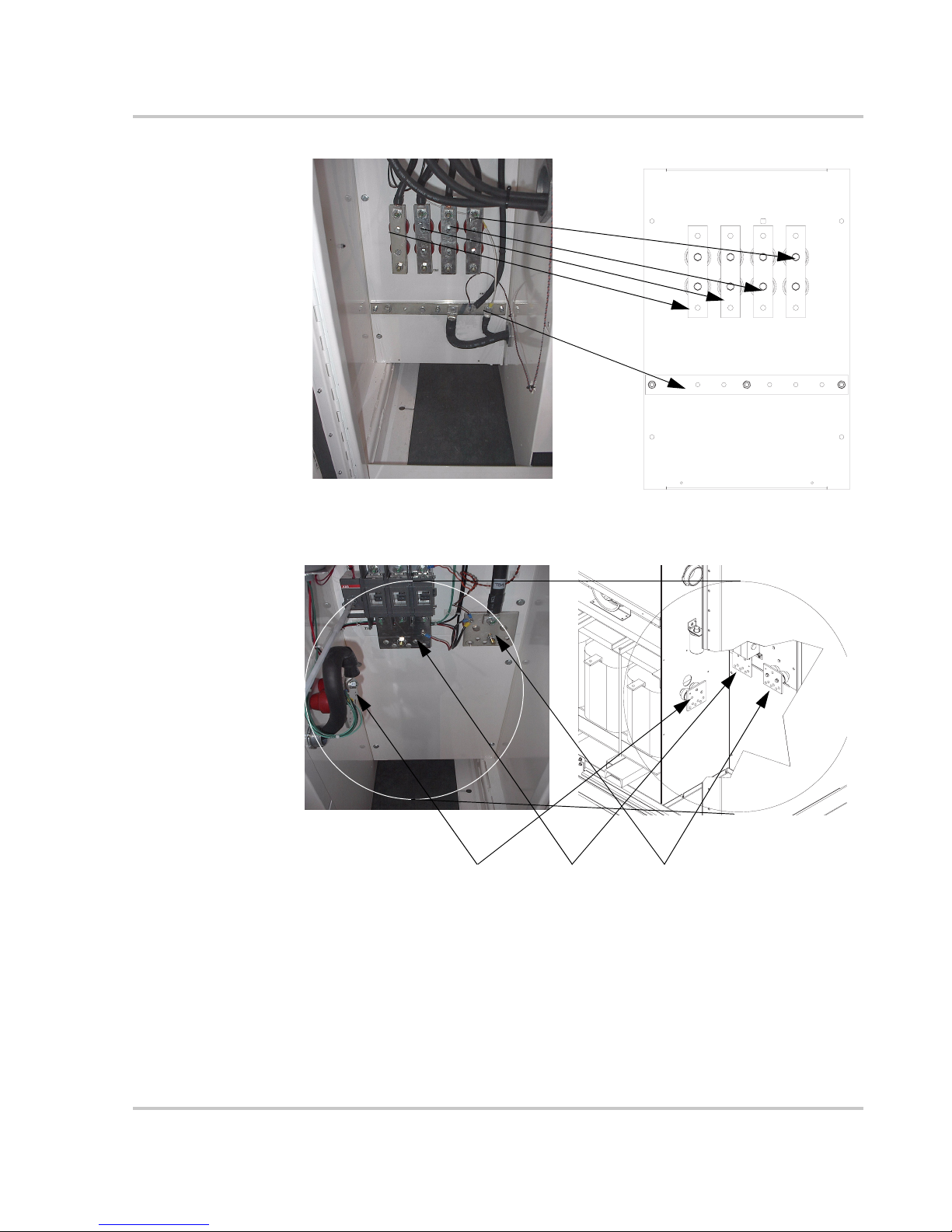
Figure 1-1 Main Inverter (Open Enclosure View) - - - - - - - - - - - - - - - - - - - - - - - - - - - - - - - - - 1–3
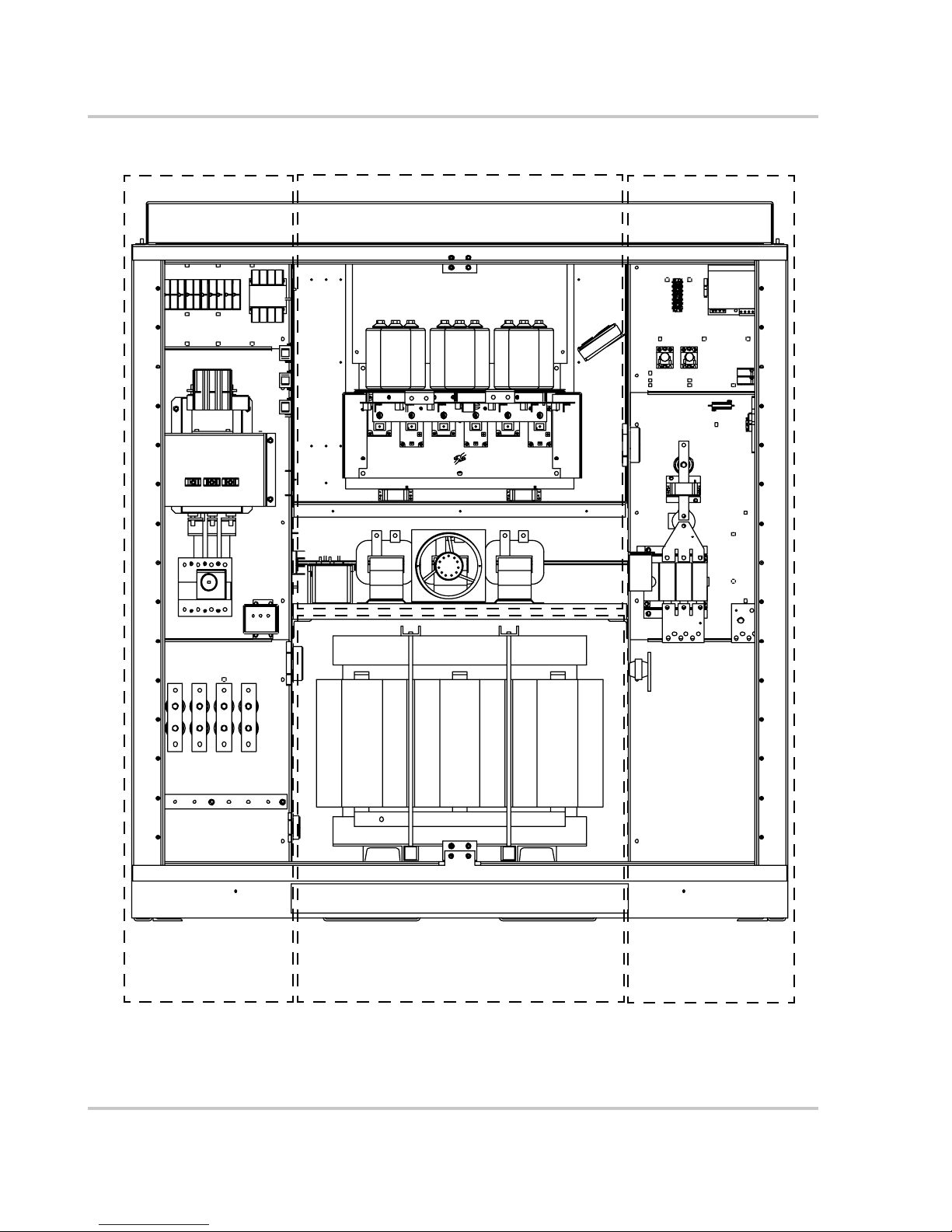
Figure 1-2 GT100 Major Sections - - - - - - - - - - - - - - - - - - - - - - - - - - - - - - - - - - - - - - - - - - - - 1–4
Figure 1-3 AC Utility Terminals - - - - - - - - - - - - - - - - - - - - - - - - - - - - - - - - - - - - - - - - - - - - - 1–5
Figure 1-4 Auxiliary Control Terminals - - - - - - - - - - - - - - - - - - - - - - - - - - - - - - - - - - - - - - - - 1–6
Figure 1-5 DC Terminals- - - - - - - - - - - - - - - - - - - - - - - - - - - - - - - - - - - - - - - - - - - - - - - - - - 1–8
Figure 1-6 GT Fused Combiner Connectors - - - - - - - - - - - - - - - - - - - - - - - - - - - - - - - - - - - - - 1–9
Figure 1-7 GT100 Circuit Diagram - - - - - - - - - - - - - - - - - - - - - - - - - - - - - - - - - - - - - - - - - - - 1–10
Figure 1-8 GT100 Operator Interface Components - - - - - - - - - - - - - - - - - - - - - - - - - - - - - - - - 1–11
Figure 1-9 On/Off Switch - - - - - - - - - - - - - - - - - - - - - - - - - - - - - - - - - - - - - - - - - - - - - - - - - 1–12
Figure 1-10 AC and DC Disconnect Switches- - - - - - - - - - - - - - - - - - - - - - - - - - - - - - - - - - - - - 1–13
Figure 1-11 Maximum Peak Power Tracking - - - - - - - - - - - - - - - - - - - - - - - - - - - - - - - - - - - - - 1–15
Figure 1-12 VFD Display and UFCU Location - - - - - - - - - - - - - - - - - - - - - - - - - - - - - - - - - - - - 1–18
Figure 2-1 State Transition Diagram - - - - - - - - - - - - - - - - - - - - - - - - - - - - - - - - - - - - - - - - - - 2–3
Figure 2-2 Operating States Flow Chart for Power Tracking - - - - - - - - - - - - - - - - - - - - - - - - - - 2–6
Figure 2-3 The Universal Front Panel Control Unit (UFCU) and VFD - - - - - - - - - - - - - - - - - - - 2–7
Figure 2-4 Initialization Screens - - - - - - - - - - - - - - - - - - - - - - - - - - - - - - - - - - - - - - - - - - - - - 2–8
Figure 2-5 Operator Interface Menu Diagram - - - - - - - - - - - - - - - - - - - - - - - - - - - - - - - - - - - - 2–10
Figure 2-6 Scrolling through the Read Menu - - - - - - - - - - - - - - - - - - - - - - - - - - - - - - - - - - - - 2–12
Figure 2-7 Read-by-ID Feature- - - - - - - - - - - - - - - - - - - - - - - - - - - - - - - - - - - - - - - - - - - - - - 2–15
Figure 2-8 State Transition Diagram - - - - - - - - - - - - - - - - - - - - - - - - - - - - - - - - - - - - - - - - - - 2–22
Figure 2-9 VFD showing Fault Code - - - - - - - - - - - - - - - - - - - - - - - - - - - - - - - - - - - - - - - - - - 2–25
Figure 2-10 AC Utility Terminals - - - - - - - - - - - - - - - - - - - - - - - - - - - - - - - - - - - - - - - - - - - - - 2–27
Figure 2-11 DC Terminals- - - - - - - - - - - - - - - - - - - - - - - - - - - - - - - - - - - - - - - - - - - - - - - - - - 2–28
Figure 4-1 VFD showing Fault Code - - - - - - - - - - - - - - - - - - - - - - - - - - - - - - - - - - - - - - - - - - 4–4
Figure 5-1 AC Terminal Connections from the Utility - - - - - - - - - - - - - - - - - - - - - - - - - - - - - - 5–3
Figure 5-2 DC Terminal Locations - - - - - - - - - - - - - - - - - - - - - - - - - - - - - - - - - - - - - - - - - - - 5–4
Figure 5-3 DC Terminal Locations (with GTFC installed) - - - - - - - - - - - - - - - - - - - - - - - - - - - 5–4
Figure A-1 GT100 Dimensions - - - - - - - - - - - - - - - - - - - - - - - - - - - - - - - - - - - - - - - - - - - - - - A–6
153378 xix
Page 22

xx
Page 23

Tables
Table 1-1 DC Terminal Polarity - - - - - - - - - - - - - - - - - - - - - - - - - - - - - - - - - - - - - - - - - - - - 1–8
Table 1-2 DC Terminal Polarity (with GTFC) - - - - - - - - - - - - - - - - - - - - - - - - - - - - - - - - - - - 1–9
Table 2-1 Scrolling through the Read Menu Parameters - - - - - - - - - - - - - - - - - - - - - - - - - - - - 2–11
Table 2-2 Read Menu Descriptions - - - - - - - - - - - - - - - - - - - - - - - - - - - - - - - - - - - - - - - - - - 2–13
Table 2-3 Write Menu Parameters - - - - - - - - - - - - - - - - - - - - - - - - - - - - - - - - - - - - - - - - - - - 2–17
Table 4-1 Fault Codes - - - - - - - - - - - - - - - - - - - - - - - - - - - - - - - - - - - - - - - - - - - - - - - - - - - 4–5
Table A-1 Environmental Specifications - - - - - - - - - - - - - - - - - - - - - - - - - - - - - - - - - - - - - - - A–2
Table A-2 Electrical Specifications - - - - - - - - - - - - - - - - - - - - - - - - - - - - - - - - - - - - - - - - - - - A–3
Table A-3 Regulatory Specifications- - - - - - - - - - - - - - - - - - - - - - - - - - - - - - - - - - - - - - - - - - A–3
Table A-4 Over/Under Voltage and Over/Under Frequency Ranges - - - - - - - - - - - - - - - - - - - - - A–4
Table A-5 AC Terminal Bolt Size and Torque Values - - - - - - - - - - - - - - - - - - - - - - - - - - - - - - A–5
Table A-6 DC Terminal Bolt Size and Torque Values - - - - - - - - - - - - - - - - - - - - - - - - - - - - - - A–5
Table A-7 DC Terminal Conductor Range and Torque Values - - - - - - - - - - - - - - - - - - - - - - - - A–5
Table A-8 Auxiliary Control Interface Screw Size and Torque Values - - - - - - - - - - - - - - - - - - - A–6
153378 xxi
Page 24

xxii
Page 25

1
Introduction
Chapter 1, “Introduction” contains information about the features and
functions of the GT100 Grid-Tied Photovoltaic Inverter.
Page 26

Introduction
Description of the GT100
The GT100 Grid-Tied Photovoltaic Inverter is a utility interactive, three-phase
power conversion system for grid-connected photovoltaic arrays with a power
rating of 100 kW. Designed to be easy to install and operate, the GT100 automates
start-up, shutdown, and fault detection scenarios. With user-definable power
tracking that matches the inverter to the array and adjustable delay periods, users
are able to customize startup and shutdown sequences. Multiple GT100 inverters
are easily paralleled for larger power installations.
Power Conversion System
The GT100 power conversion system consists of a pulse-width modulated (PWM)
inverter, switch gear for isolation and protection of the connected AC and DC
power sources. Housed in a rugged NEMA-3R rated, corrosive resistant, powdercoated steel enclosure, the GT100 incorporates sophisticated Insulated Gate
Bipolar Transistors (IGBTs) as the main power switching devices. An advanced,
field-proven, Maximum Peak Power Tracker (MPPT) integrated within the
GT100 control firmware ensures the optimum power throughput for harvesting
energy from the photovoltaic array.
Advanced Design Features
The advanced design of the GT100 includes an EMI output filter and the main AC
contactor located electrically on the utility side of the isolation transformer to
minimize transformer tare losses when the unit is not operating.
The GT100 also includes an Inrush Limit assembly to prevent nuisance Utility
Circuit Breaker trips when the isolation transformer is energized.
A sophisticated control scheme optimizes the operation of the GT100 cooling fan
as needed for increased overall system efficiency.
Additionally, the GT100 integrated controller contains self-protection features
including over and under voltage and frequency safeguards in compliance with
UL 1741 Rev 2005.
Anti-islanding An integral anti-island protection scheme prevents the inverter from feeding
power to the grid in the event of a utility outage.
Auto-Phase
Rotation
The GT100 includes the ability to auto-sense and correct for a “mis-phased”
connection at the AC Interface terminals. In the event the power conductors from
the utility are not phased correctly at the AC Interface terminals, the GT100 will
sense the discrepancy and automatically correct for a clockwise (A-B-C)
phase rotation.
1–2 153378
Page 27

Physical Characteristics
Local Display and
Remote Graphic
User Interface
The GT100 includes a local user interface comprised of an ON/OFF switch,
keypad, and 4-line, 80 character VFD display.
A user-friendly, Xantrex GT View Graphic User Interface (GUI) provides a
remote interface for operator interrogation of GT100 system status, control,
metering/data logging and protective functions within the GT100. The status,
control, and logging features are supported by an optional modem via an RS232
connection for remote monitoring. Alternatively, a user selectable RS485/Modbus
connection is also available for remote plant monitoring.
Physical Characteristics
The GT100 is assembled in a single NEMA-3R, corrosive resistant, powdercoated enclosure that includes two access doors to house the electronics described
above. Internally, the GT100 is compartmentalized to include sections for the AC
Interface (left side), the Power Electronics (upper middle), the Isolation
Transformer (lower middle), and the DC Interface (right side). The single
enclosure is constructed and delivered as one complete assembly.
These sections are identified in Figure 1-2 on page 1–4.
Figure 1-1
153378 1–3
Main Inverter (Open Enclosure View)
Page 28
Introduction
Power Electronics section
AC Interface
section
Figure 1-2
GT100 Major Sections
1–4 153378
Isolation Transformer section DC Interface
section
Page 29
AC Interface
AC Utility Terminals
Physical Characteristics
The AC Interface serves as the connection for the utility (see Figure 1-2 to locate
the AC Interface). This compartment (section) houses the AC Terminals (TB1-N,
-A, -B, and -C), AC Disconnect, AC Contactor, and EMI Filter. Additionally, the
Inrush PCB assembly, control power transformer, control fuses, and AC sensing
circuitry are also housed in this section.
Figure 1-3
AC Utility Terminals
Each terminal provides one hole with space for two cables with a M10 bore
diameter (see Table A-5 on page A–5 for torque requirements).
153378 1–5
Page 30
Introduction
Auxiliary Control Interface
The GT100 has provisions within the AC Interface for installing auxiliary control
signals that include a remote Emergency Stop and a remote Enable/Disable signal.
Auxiliary Control via the remote Enable/Disable signal is advantageous for
coordination of the GT100 at specific installations where a pre-existing back-up
emergency generator is present.
Two separate dry contact circuits at the TB7 terminal are used for control of these
input signals. Circuit termination and signal type are identified in Figure A-8 on
page A–6.
Figure 1-4
Auxiliary Control Terminals
Communications Circuit
The GT100 can be remotely accessed through an RS232 serial port or through an
RS485/Modbus connection. Xantrex offers modems that can be connected to the
RS232 port for remote monitoring. The remote user has the ability to control and
monitor the status of the inverter through this connection.
Alternatively, a user selectable RS485/Modbus connection is also available for
remote plant monitoring. The CCU2 Controller board within the GT100 may be
configured for RS485 serial communication using the Modbus protocol. This
enables users to monitor and control the inverter from a dedicated plant wide
monitoring system.
1–6 153378
Page 31

Power Electronics
The GT100 Power Electronics section contains the converter control unit (CCU2)
and the power electronics matrix. Also found within the Power Electronics section
are the Hall-effect current transducers, and an internal air circulation fan.
Converter Control Unit (CCU2)
The CCU2 is a Digital Signal Processor (DSP) based control board that performs
numerous control and diagnostic functions associated with GT100 operation. Its
most significant tasks are control of GT100 electromechanical components and
power electronics converters, communication with the Universal Front Panel
Control Unit, and system sensors. The CCU2 also contains the necessary DC
power supplies to support its operation.
Power Electronics Matrix
The power electronics converter matrix consists of switching transistors (IGBTs),
transistor gate drive electronics, laminated DC bus structure, DC capacitors and
an aluminium extrusion heatsink with a cooling fan. The fan is located behind the
matrix assembly and forces air down through the heatsink.
The PV array is tied logically to the matrix DC bus within the DC Interface
section. The embedded CCU2 control unit manages the transfer of power between
the DC bus and the utility grid.
Physical Characteristics
153378 1–7
Page 32

Introduction
DC Interface
DC Terminals
The DC Interface serves as the connection interface between the PV array and the
GT100 (see Figure 1-2 on page 1–4 to locate the DC Interface). This section
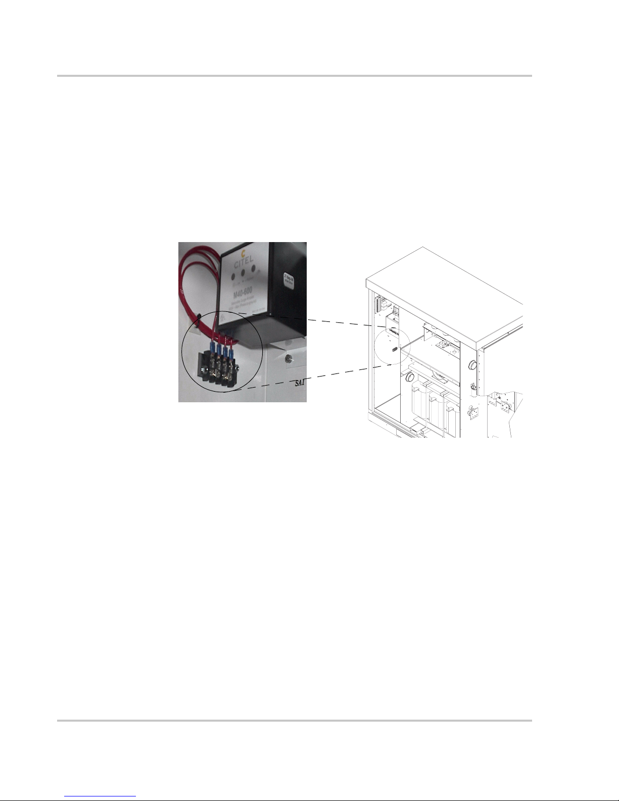
houses the DC Disconnect Switch and DC contactor. Additionally, the PV Ground
Fault Detection circuitry, DC surge arrestor, Solid State Relays, and 48Vdc Power
Supply are also housed in this section.
WARNING: Shock Hazard
Xantrex recommends the installation of PV array disconnect(s) to ensure personal safety
during GT100 maintenance. WITHOUT PV ARRAY DISCONNECT(S), ONCE THE
DC DISCONNECT SWITCH (S1) IS OPEN, THERE WILLSTILL BE DC
VOLTAGE on the DC terminals TB3, TB4 AND TB5 (PV GND). This voltage may be
as high as the open-circuit voltage of the PV Array and is limited to 600Vdc per NEC 690.
Use extreme care to avoid these terminals if no PV array disconnect is installed.
TB5
(PV GND)
Figure 1-5
DC Terminals
The terminals provide six holes with space for twelve cables with a M10 bore
diameter per pole (see Table A-6 on page A–5 for torque requirements).
The table below describes the DC terminal polarity for each GT100 model.
Table 1-1
Model TB3 TB4 TB5
GT100-208-NG PV+ PV– PV GND
GT100-208-PG PV– PV+ PV GND
GT100-480-NG PV+ PV– PV GND
GT100-480-PG PV– PV+ PV GND
1–8 153378
TB3
TB4
DC Terminal Polarity
Page 33

Fused Combiner (Optional)
Physical Characteristics
Figure 1-6
TB5
(PV GND)
GT Fused Combiner Connectors
The fuse blocks of the optional Fused Combiner (GTFC) assembly provide one
box style connector per pole (see Table A-7 on page A–5 for acceptable wire
range and torque requirements.)
The table below describes the DC terminal polarity for each GT100 model with
the GTFC installed.
Table 1-2
Model GTFC TB4 TB5
GT100-208-NG PV+ PV– PV GND
GT100-208-PG PV– PV+ PV GND
GT100-480-NG PV+ PV– PV GND
GT100-480-PG PV– PV+ PV GND
DC Terminal Polarity (with GTFC)
GTFC TB4
153378 1–9
Page 34

Introduction
T1
D
Circuit Diagram
A
AC GRID
B
3 PHASE 60HZ
C
N
GND
Figure 1-7
TB1
A
B
C
N
TB2
SINGLE POINT
TO
EARTH GROUND
CB1
BOT
TOP
4
3
6
5
8
7
2
1
GT100 Circuit Diagram
FILTER
LF1
EMI
L1
L2
L3
K1
AC CONTACTOR
INRUSH LIMIT CCU2
100KVA
H1
X1
H2
X2
H3
X3
H0
SH
A
B
C
POWER
MATRIX
K2
A2
A1
F4
S1
1
536
2
4
TB3
TB4
R1
TB5
PV GN
1–10 153378
Page 35

Operator Interface Controls
Operator interface controls are located on the left front door of the main Inverter
Enclosure. These controls include an ON/OFF Switch, 4-line VFD display and
keypad called the Universal Frontpanel Control Unit (UFCU) used to manipulate
and view system operation and status. The keypad is comprised of 20 touchsensitive keys that provide a means to navigate through the menus and alter userchangeable settings. Additionally, there is an AC Disconnect switch handle and
DC Disconnect switch handle on the AC Interface door (left) and the DC Interface
door (right) respectively.
VFD
Display
Operator Interface Controls
Universal
Frontpanel
Control
(UFCU)
On/Off
Switch
AC Disconnect
(CB1)
DC Disconnect
Switch (S1)
AC Interface
Figure 1-8
153378 1–11
GT100 Operator Interface Components
DC Interface
Page 36

Introduction
On/Off Switch
The GT100 incorporates a maintained position ON/OFF switch located on the left
front door, under the UFCU. Under normal operating conditions, the
ON/OFF
switch is in the ON position. Turning the switch to the OFF position will initiate an
immediate controlled shutdown of the GT100 and open both the main AC and DC
contactors within the unit. The main AC and DC contactors cannot be closed
unless the switch is in the
restarted until the
ON/OFF switch is turned back to the ON position.
ON position. The GT100 is prevented from being
WARNING: Shock Hazard
Turning the ON/OFF switch to the OFF position does NOT remove all hazardous voltages
from inside the inverter. Before attempting to service the GT100, follow the de-energize
Lockout and Tag procedure on page xii and page 5–2.
Figure 1-9
Emergency Stop (E-STOP)
Provisions are supplied for adding a remote emergency stop. Circuit termination
and signal type are identified in Table A-8 on page A–6.
Auxiliary Enable/Disable
The GT100 also has provisions for installing an auxiliary Enable/Disable switch
in series with the local control. This is advantageous for coordination of the
GT100 at specific installations where a pre-existing back-up emergency generator
is present. Circuit termination and signal type are identified in Table A-8 on
page A–6
1–12 153378
On/Off Switch
Page 37

AC Disconnect and DC Disconnect Switches
Both enclosure doors of the GT100 are equipped with lockout hasps for personnel
safety. The enclosure doors should not be opened while the GT100 is operating.
The switch handles and shafts provide a mechanical door interlock for both the
AC and DC Interface sections. The doors cannot be opened when the switches are
in the
ON position.
Although the Main ON/OFF switch (S3) is recommended for an orderly
shutdown, the DC Disconnect switch is equipped with an auxiliary contact block
which enables the switch to be used as a load break DC disconnect. In the event
the DC Disconnect switch is opened while the GT100 is processing power from
the PV array, the early-break contact block will signal the CCU2 (Converter
Control Unit) to stop processing power prior to opening the DC Disconnect
switch.
Additionally, opening the DC Disconnect switch will cause the GT100 to execute
an immediate orderly shutdown, open both the main AC and DC contactors, and
report a PV disconnect fault on the VFD of the UFCU.
Both GT100 enclosure doors must be closed and locked during normal operation.
Operator Interface Controls
AC Disconnect
switch (CB1)
AC Interface
Figure 1-10
153378 1–13
AC and DC Disconnect Switches
DC Interface
DC Disconnect
switch (S1)
Page 38

Introduction
Operation Features
The GT100 has the following operation features.
Fixed Unity Power Factor Operation
The GT100 maintains unity power factor during operation. The control software
constantly senses utility voltage, and constructs the output current waveform to
match the utility voltage. The GT100 is not capable of operation without the
presence of normal utility voltage, nor is it capable of varying the output power
factor off unity.
Peak Power Tracking
An advanced, field-proven, Maximum Peak Power Tracker (MPPT) algorithm
integrated within the GT100 control software ensures the optimum power
throughput for harvesting energy from the photovoltaic array. The peak power
voltage point of a PV array can vary, primarily depending upon solar irradiance
and surface temperature of the PV panels. This peak power voltage point is
somewhat volatile, and can easily move along the I-V curve of the PV array every
few seconds. The MPPT algorithm allows the GT100 to constantly seek the
optimum voltage and current operating points of the PV array, and maintain the
maximum peak PV output power.
Accessible via the UFCU, there are five user-settable parameters that control the
behavior of the maximum peak power tracker within the GT100. As show in
Figure 1-11 on page 1–15, user settable parameters include:
• PPT V Ref (ID# 37),
• I PPT Max (ID#42),
• PPT Enable (ID# 44),
• PPT Rate (ID# 45), and
• PPT V Step (ID# 46).
Upon entering the Power Tracking mode, it takes approximately 20 seconds for
the GT100 to ramp the PV voltage to the “PPT V Ref” setpoint regardless of the
actual PV voltage.
With the “PPT Enable” set to “0” (power tracker disabled), the GT100 will
regulate the DC Bus at the “PPT V Ref” setpoint. Regulating the DC bus means
drawing more or less current out of the PV array to maintain this desired voltage.
With the “PPT Enable” set to “1” (power tracker enabled), followed by the
expiration of the “PPT Rate” (MPPT decision frequency), the MPPT will reduce
the reference voltage by an amount equal to the “PPT V Step” value.
At this point the MPPT will compare the amount of AC output power produced to
the previous amount of AC power produced by the GT100. If the output power
has increased, the next change made (after “PPT Rate” has again expired) to the
reference voltage, will be in the same direction.
1–14 153378
Page 39

Operation Features
Conversely, if the power comparison proves undesirable, the power tracker will
reverse the direction of the change to the “PPT_V Step”. The MPPT algorithm
within the GT100 will then continue this ongoing process of “stepping and
comparing” in order to seek the maximum power throughput from the PV array.
The changes made by the MPPT to the reference voltage are restricted to ± 40% of
“PPT V Ref” and by the maximum and minimum PV input voltage (600 and
300 V respectively). Also, the MPPT will not attempt to produce power greater
than that allowed by the “I PPT Max” setpoint. If available PV power is above the
maximum allowable power level of the GT100, the MPPT will increase voltage as
needed to maintain output power below the rated maximum.
Optimization of the GT100 MPPT will result in an increase in energy production.
The user is encouraged to study the PV array’s I-V curves and to adjust the MPPT
user settable parameters accordingly.
Figure 1-11
Maximum Peak Power Tracking
Utility Voltage/Frequency Fault Automatic Reset
In the event of a utility voltage or frequency excursion outside of preset limits, the
GT100 will stop operation and display a fault at the operator interface. Once the
utility voltage has stabilized within acceptable limits for a period of at least
5 minutes, the GT100 will automatically clear the fault and resume normal
operation. Voltage and frequency fault setpoints are detailed later in this section.
153378 1–15
Page 40

Introduction
Safety Features
Anti-Island Protection
A condition referred to as "Islanding" occurs when a distributed generation source
(such as the GT100 Grid-tied Photovoltaic Inverter) continues to energize a
portion of the utility grid after the utility experiences an interruption in service.
This type of condition may compromise personnel safety, restoration of service,
and equipment reliability.
The GT100 employs a method for detecting the islanding condition using a PhaseShift-Loop (PSL). This method is implemented in the CCU2 to prevent islanding
of the GT100. The CCU2 continuously makes minor adjustments to the power
factor phase angle above and below unity. In the event of a utility interruption or
outage, these adjustments destabilize the feedback between the inverter and the
remaining load, resulting in an over/under frequency or voltage condition.
Upon detection of such a condition, the GT100 then performs an immediate
orderly shutdown and opens both the main AC and DC contactors. The fault
condition will remain latched until the utility voltage and frequency have returned
to normal for at least 5 minutes.
This method has been extensively tested and proven to exceed the requirements of
IEEE-929 (Recommended Practices for Utility Interface of Photovoltaic [PV]
Systems) and UL 1741 (Static Inverters and Converters for use in Independent
Power Systems).
PV Ground Fault Detection
The GT100 is equipped with a PV Ground Fault Detection and Interruption
circuit. The circuit employs a 4 A fuse between TB4 and TB5 (PV GND). If
sufficient ground current clears the fuse, and auxiliary contact will signal the
GT100 to execute an immediate orderly shutdown, open both the AC and DC
contactors and report a PV Ground on the VFD of the UFCU. The GT100 will
remain faulted until the fault is remedied, the fuse is replaced, and the advisory is
cleared at the operator interface.
DC Over-voltage Detection
In the event of DC voltage greater than 600 Vdc, the GT100 will execute an
orderly shutdown and will report a PV over-voltage fault on the VFD of the
UFCU. If the DC voltage remains greater than 600 Vdc, the GT100 may be
irreparably damaged.
See Chapter 4, “Troubleshooting” for further information on this fault condition.
1–16 153378
Page 41

Communication Features and Methods
The GT100 provides three types of information to the user:
• system status and/or fault information,
• data logging information, and
• oscillography.
System status and fault information can be accessed using the Universal Front
Panel Control Unit (UFCU), via an RS232 connection to a PC or via an RS485/
Modbus connection to a remote monitoring system. Data logging and
oscillography is available via the RS232 or the RS485/Modbus connection.
The GT100 communicates system status information to the user using the
following methods.
• The Front Panel Control Unit (UFCU) Display
• PC Connection (Remote) - GT View Graphic User Interface (GUI) Software
required (may require additional hardware)
• External Monitoring - (Optional) via a RS485/Modbus connection for remote
plant monitoring.
Communication Features and Methods
System Status and Fault Reporting
Basic system status and all fault conditions rising from within the GT100 are
reported to the UFCU. The 4-line VFD will display a hexadecimal value and a
brief text description of the fault. Additionally, the CCU2 stores the time and
details of all faults in non-volatile memory for later retrieval.
The fault value is also made available to the GT View Graphic User Interface
(GUI) via the RS485/Modbus protocol and will include a more extensive
description of the fault.
Types of status information include:
• Current Operating State or Goal State
• Fault Code (if applicable)
• Inverter State
• Line Voltage and Current
• Inverter Matrix Temperature
•Inverter Power
•PV State
• PV Voltage and Current
• PV Power
• Grid Frequency
• Peak Power Tracker Enabled
153378 1–17
Page 42

Introduction
Universal Front
Panel Control Unit
(UFCU)
Figure 1-12
VFD Display and UFCU Location
1–18 153378
VFD Display
Page 43

Data Logging
Communication Features and Methods
The GT100 inverter stores data values and software metrics for debugging. The
firmware maintains a data log located in the CCU2 non-volatile memory with a
capacity of 25840 32-bit words. The GT100 records the 17 parameters listed
below, and logs them into a circular buffer, such that the earliest records shall be
overwritten once the capacity of the buffer is exceeded. The log capacity is
25840 / 20 = 1292 records (each record has 2 words for timestamp and 18 words
for parameters). Data logging requires the use of a PC connection using the GT
View Graphic User Interface (GUI) software or via the RS485/Modbus
connection.
The following is the list of parameters which values shall be stored in the data
logging records:
•Inverter Vab
•Inverter Vbc
•Inverter Vca
• I Phase A
• I Phase B
• I Phase C
•Grid Freq
•Real Power
• PV Voltage
• PV Current
• PV Power
•System State
•Fault Code
• Intake air Temp.
•Matrix Temp.
• Analog input
• Fan speed control
153378 1–19
Page 44

Introduction
Oscillography
The GT100 includes a graphic data analysis tool known as Oscillography. The
inverter firmware continuously records, in the CCU2 non-volatile memory, 500
samples of data at 1 millisecond intervals. Of these, 250 samples are taken right
before a fault occurs and 250 samples are taken after the fault. Once a fault occurs
and the 250 samples are logged, the log stops and goes into DONE status. The log
will start recording again as soon as the fault is cleared. Oscillography requires the
use of a PC connection using the GT View Graphic User Interface (GUI) software
or via the RS485/Modbus connection.
The following is the list of parameters which instant values shall be stored in the
oscillography records:
• Vab - Grid voltage phase A to phase B
• Vbc - Grid voltage phase B to phase C
• Vca - Grid voltage phase C to phase A
• Ia - Grid current phase A
• Ib - Grid current phase B
• Ic - Grid current phase C
• Grid Hz - Grid frequency
• DC_V - PV array voltage
• DC_I - PV array current
• Fault - hexadecimal code of the fault
1–20 153378
Page 45

Optional Equipment
The following options are available for purchase for use with the GT100 to
enhance its capability. Contact a Xantrex distributor for further information on
installation options.
Communication Modems
Xantrex offers modems that can be connected to the RS232 serial port for remote
monitoring of the inverter. Please check with Xantrex on available modem types.
The remote user has the ability to control and monitor the status of the inverter
through this connection.
PV Combiner
The GT100 is available with an optional fused sub-array combiner (GTFC).
The GTFC-fused combiner is integrated in the inverter enclosure and allows for
multiple runs from the PV Arrays to the inverter directly into a fuse for
circuit protection.
The GTFC Fused Combiner assemblies are available for the GT100 Grid-Tied
Photovoltaic Inverter in the following configurations.
• GTFC 100A (Xantrex p/n 1-153509-01),
six individual Class RK5 fuses rated at 100A
• GTFC 150A (Xantrex p/n 1-153510-01),
four individual Class RK5 fuses rated at 150A
• GTFC 200A (Xantrex p/n 1-153511-01),
three individual Class RK5 fuses rated at 200A
See Figure 1-6 on page 1–9 and Table 1-2 on page 1–9 for the location and
polarity of these assemblies.
Optional Equipment
153378 1–21
Page 46

1–22
Page 47

2
Operation
Chapter 2, “Operation” contains information on the basic operation of
the GT100 Grid-Tied Photovoltaic Inverter.
Page 48

Operation
Description of System Operation
Overview
The GT100 is a fully automated grid-interactive photovoltaic power inverter.
System startup, system shutdown, PV power tracking, and fault detection
scenarios are all governed and monitored by the CCU2 controller within the
GT100. Manual interaction or control of the inverter is necessary only in the
event of a system fault. Additionally, the following conditions govern operation
of the GT100.
• Stable utility AC voltage and frequency as specified in Table A-4 must be
present for all states of operation.
• PV voltage as specified in Table A-2 must be present.
• With the exception of the Matrix Test state, the
the front door of the GT100 Inverter Enclosure, must be switched to the
position for all operating states.
• Both the AC and DC Disconnect switches must be in the ON or
closed position.
• Fault conditions must not be present.
ON/OFF switch (S3), located on
ON
Faults
Fault states are automatic from any state of operation. In the event of a fault
condition, the GT100 will immediately stop processing power and execute an
immediate orderly shutdown, open both the main AC and DC contactors, and
remain in a faulted state until the fault is remedied and cleared (manually or
automatically).
Most faults are latching, and only those faults associated with grid disturbances
and Air Duct Intake temperature are auto-clearing and thus enable the GT100 to
restart after a delay period. All fault conditions arising from within the GT100 are
reported to the UFCU (Universal Frontpanel Control Unit). The 4-line VFD on
the UFCU will display a hexadecimal value (fault code) and a brief text
description of the fault.
Once the cause of the fault has been identified and corrected, and it is determined
to be safe to proceed, GT100 faults may be cleared from the UFCU keypad or via
the remote GUI.
See “Clearing Faults Manually” on page 4–4 for instructions on this procedure.
2–2 153378
Page 49

Operating States
A state machine implemented within the CCU2 control software governs the
operation of the GT100 with clearly defined transitions between its operating
states. There are five steady-state operating states and numerous intermediate
transition states.
•Shutdown
• Transition
• Power Tracking
• Automatic Sleep Test
• Manual Current
•Matrix Test
•Fault
The user should be aware of the following conditions governing GT100
state transitions:
• Qualified utility voltage must be present for all states of operation.
• Fault states are automatic from any state of operation. A fault will cause the
• Most GT100 faults are latching and must be cleared at the operator interface
•The
Operating States
GT100 to immediately stop processing all power. The fault condition will be
reported to the operator interface VFD.
keypad before transitioning to another operating state.
ON/OFF switch, located on the front door of the GT100, must be in the ON
position for all operating states except Matrix Test, in which case it must be in
OFF position.
the
SHUTDOWN
Inverter =
Disabled
Automatic
POWER
TRACKING
Inverter =
PV Power
Figure 2-1
153378 2–3
State Transition Diagram
Manual
FAULT
Manual
MATRIX
TEST
Inverter =
Idle
MANUAL
CURRENT
Inverter = PV
Current
Page 50

Operation
Shutdown
Trans ition
Power Tracking
The line interface controller is idle. The CCU2 monitors the status of the PV array
and utility grid, waiting in standby until the PV array is available to produce
power to the grid.
The intermediate transition states provide an orderly progression from one
operating state to the next. The user has the ability to manually transition the
GT100 between operating states via the operator interface keypad or remotely
using the GUI software. Manual transitions are initiated by entering a “Goal
State”, where the goal state is the desired operating state. Given all applicable
system parameters are within acceptable limits, and the request is valid within the
state machine, the GT100 will initiate the proper sequence of operations necessary
to progress to the requested goal state. Refer to Figure 2-1 on page 2–3 for an
illustration of valid state transitions.
This is the standard operating state of the GT100. The GT100 maximum power
tracker will demand maximum power from the PV array, given sufficient PV
irradiance. Refer to Figure 2-2 on page 2–6 for an illustration of valid operating
states for Power Tracking.
Automatic Sleep Test
Toward the end of every solar day, the GT100 automatically determines when to
stop producing power dependent upon the output power of the inverter. As the net
output power of the GT100 nears zero, a timer is started to allow the inverter to
ride through any brief irradiance reductions.
Manual Current
This operating state is provided to evaluate the existing PV array V-I
characteristics. The PV controller regulates a constant amount of PV current as
commanded by the user from the operator interface keypad, up to the PV current
limit of the GT100. If the user commands more PV current than is available, the
DC bus voltage will drop below the minimum bus voltage level and the GT100
will enter Shutdown mode.
2–4 153378
Page 51

Matrix Test
Fault
Operating States
This operating state is provided to verify proper operation of the matrix and
associated control electronics. In this state, the CCU2 will send digitized gating
signals (On/Off) to the IGBTs at a 2 Hz rate. There is no power transfer between
the PV and utility in this mode. The
ON/OFF switch must be in the OFF position for
the GT100 to enter this state.
The GT100 has encountered a fault condition. When this happens, regardless of
the GT100 state of operation, the GT100 will stop processing all power and
execute an orderly system shutdown. A description of the fault and fault code will
appear on the operator interface VFD. The Fault state may be cleared from the
keypad once the cause of the fault has been corrected. See Chapter 4,
“Troubleshooting” for a complete description of all fault codes.
See next page for the Operating States Flow Chart for Power Tracking.
153378 2–5
Page 52

Operation
System State: Switched Off
System State: Key Disable
Inverter State: Standby
Inverter State: Standby
PV State: Sleep
PV State: Sleep
POWER UP
INITIALIZING
INITIALIZING
PV contactor opened.
PV contactor opened.
Inverter matrix off.
Inverter matrix off.
Grid contactor open.
Grid contact or open.
CCU2 Green LED on.
Green LED on. Red off.
Red Off.
SWITCHED
KEY
OFF
DISABLE
PV contactor open.
Inverter matrix off.
Grid contact or open.
Enable Key
Inverter matrix off. Line contactor open
System State: Shutdown
Inverter State: Standby
PV State: Sleep
PV Voltage > 440V
(PV V START)
System State: Shutdown
Inverter State: Standby
PV State: Wake Up
Grid Contactor K1 Close
System State: Shutdown
Inverter State: Main Settling
PV State: Wake Up
Inverter Matrix On
System State: Power Tracking
Inverter State: On Line
PV State: On Line
SLEEP
for at least 10
seconds
WAKE UP
for 5.0 min.
(PV T START)
K1 Settle
for .5 seconds
ON LINE
PV Voltage >
PV Voltage <
PV Voltage < 440V (PV V Start)
PV Voltage <
PV Power < 1.0kW (PV P STOP)
PV Power > 1.0kW (PV P STOP)
300V
Close K2
50V (300V - 250V
300V (Min. Oper.)
margin)
TEST
for 5.0 min.
(PV T STOP)
PV Contactor Closed
PV Contactor Open
PV Voltage <
5 minutes elapsed
300V (Min. Oper.)
Retrun to Sleep State
Return to Sleep State
FAULT
Fault from any State Fault Cleared
Figure 2-2
Operating States Flow Chart for Power Tracking
PV contactor opened.
Inverter matrix off.
Grid contact or open.
Red LED on. Green off.
2–6 153378
System State: Power Tracking
Inverter State: On Line
PV State: Sleep Test
Bold
- constant value
Italic - User settable.
Underline
- Default value.
Page 53

Operator Interface
The purpose of the operator interface is to provide a means of communicating
critical operational information to and from the unit. This communication occurs
between the operator and the UFCU Keypad and VFD display or between the
operator and a personal computer running the GT View GUI software. The
RS485/Modbus connection is also available for remote monitoring and
control systems.
UFCU Keypad Operation and VFD Display
The UFCU keypad is located on the left front door of the inverter enclosure to
manipulate and view system operation and status.
The keypad is comprised of 20 touch-sensitive, membrane switch keys that
provide a means to navigate through the menus and alter user-changeable settings.
System: PWR Tracking
Inverter: Online
PV: Online
<Read Menu Item>
Operator Interface
Standard Display
VFD Display
UFCU Keypad
Figure 2-3
The Universal Front Panel Control Unit (UFCU) and VFD
1. Four function keys are available.
• F1 - While in the R
Volts
”. If the GT100 is faulted while in the Read Menu, this key is used
to send the “
Menu, this key is used to set “
• F2 - While in the R
While in the W
• F3 - While in the R
While in the W
EAD Menu, this key jumps to display “INV A
Clear Fault” message to the CCU2. While in the Write
Goal:”.
EAD Menu, this key jumps to display “INV kW”.
RITE Menu, this key jumps to display “PPT V Ref:”.
EAD Menu, this key jumps to display “PV kW:”.
RITE Menu, this key jumps to display “PPT Enable:”.
• F4 - While in the Read Menu, this key jumps to display “
While in the Write Menu, this key is used to both confirm and display
parameters.
– When confirming a Goal State change, this key sends the “
Goal State
” message to the CCU2.
– When re-setting the KWH, this key sends the “
message to the CCU2.
kWH:”.
Command
Reset kWH:”
153378 2–7
Page 54

Operation
– When setting all Write Menu parameters to factory default, this key
sends the “
While in the Write Menu, this key jumps to display “
Default
2. Two Navigation keys are available.
• \/ or /\ moves forward or backward within the menu structure. Upon
reaching the end of the menu, it will roll-over to the beginning of the
same menu.
3. Ten numeric keys (0 through 9), two symbol keys (“.” and “-”), and an
“E
NTER” key are available for entering user-settable parameters.
4. The “M
ENU” key allows you to enter the password-protected Write
parameters.
VFD Display - Initialization Screen
Any time AC power is applied to the unit, the VFD display will cycle through the
following displays while the system initializes. Once it’s done with this process,
the standard display will appear.
Model: GT100
XANTREX TECHNOLOGY
www.xantrex.com
151-0410-xx-xx
Set to Factory Default” message to the CCU2.
Factory
”.
Front Panel
Initialization Screen 1
System: Shutdown
Inverter: Standby
PV: Sleep...
<Read Menu Item>
<countdown>
System
Initialization Screen 2
Figure 2-4
Initialization Screens
System: Shutdown
Inverter: Standby
PV:Waking Up
<Read Menu Item>
...<countdown>
2–8 153378
Standard
Display
System: PWR Tracking
Inverter: Online
PV: Online
<Read Menu Item>
Page 55

Standard Display
Menu Structure
Operator Interface
The Standard Display provides the following information:
• First Line - System Status (ID 1)
• Second Line - Inverter Status (ID 4)
• Third Line - PV Status (ID 13)
• Fourth Line - Goal State (ID 2)
The operator interface consists of three levels:
• R
EAD Menu - operation information provided to the user from the GT100.
The Read Menu consists of all operational values, the date and time. These
can be viewed any time the GT100 has control power.
• W
RITE Menu - operational parameters provided to the GT100 from the user.
The Write Menu consists of a goal state sub-menu, and all system
configurable parameters. The Write Menu can be viewed any time the GT100
has control power. However, modifying the parameters requires a password
that may only be altered by trained service technicians. Specifically,
parameters relating to utility protection setpoints should not be modified.
• Data Logging - the collection of specific parameters values over a period of
time. The data logging feature is only available if using the GT View GUI.
See the list of stored parameters on page 1–19.
Information reported back to the user (R
EAD Menu) occurs at the VFD above the
Universal Front Panel Control Unit (UFCU) and (if used) at the computer running
the GT View GUI monitoring program. Making changes to the parameters within
the Write Menu is done with the UFCU keypad or the GUI software program and
requires a password.
Important:
the factory to the limits mandated by the UL 1741. Any changes to these setpoints should
be agreed upon by the local utility and the equipment owner.
Specific grid-interface parameters within the WRITE Menu have been set in
Upon system powerup, the operator interface VFD will display the system
operating state on the first line. The inverter’s state of operation will be reported
on the second line. The PV Array’s state of operation will be reported on the third
line. The Goal target will be reported on the fourth line.
Important:
the standard display if there is no input for more than 2 minutes.
While in the WRITE Menu, the operator interface display will reset itself to
153378 2–9
Page 56

Operation
System: PWR Tracking
Inverter: Online
PV: Online
<Read Menu Item>
Figure 2-5
READ Menu
Standard Display
Operator Interface Menu Diagram
The READ Menu includes the following information:
• Current Operating State or Goal State
• Fault Code (if applicable)
• Inverter State
• Line Voltage and Current
• Inverter Matrix and Air Duct Intake Temperature
•Inverter Power
•PV State
• PV Voltage and Current
• PV Power
• Grid Frequency
• Accumulated Power
Table 2-1 shows how the third and fourth line of the VFD will change as the
operator continues scrolling through the Menu. Table 2-2 on page 2–13 provides a
detailed description of R
the VFD.
READ Menu
W
RITE Menu
Enter Goal State
Password
EAD Menu operational values that are displayed on
Set Date/Time
Change
Parameters
To Display Any Operational Value in the R
From the Standard Display, use the /\ or \/ keys on the operator interface keypad to
scroll through the R
display the appropriate information. See Table 2-1.
• The \/ key will scroll downward through the menu.
•The /\ key will scroll upward through the menu.
2–10 153378
EAD Menu
EAD Menu. The fourth line of the display will change to
Page 57

Operator Interface
Table 2-1
Read Menu Value Fourth Line of the VFD
FP Software Version FP V151-0410-xx-xx
CCU Software Version CCU 151-0130-xx-xx
Model Name G T 1 0 0 k W
Date and Time JUN-25-2007 15:35:05
Goal State PWR Tracking
Inverter A-B Volt INV A Volts:
Inverter B-C Volt INV B Volts:
Inverter C-A Volt INV C Volts:
Inverter A Current INV A Amps:
Inverter B Current INV B Amps:
Inverter C Current INV C Amps:
Inverter AC Power INV kW:
Inverter Matrix Temperature INV Temp:
Air Duct Intake Temperature Ambient Temp:
P V Vo l t a g e P V Vol t s :
PV Current PV Amps:
PV Power PV kW:
AC Grid Frequency Grid Freq:
Accumulated Power kWH:
Scrolling through the Read Menu Parameters
When scrolling through the Read Menu Parameter list and the last item in the
menu is reached, the list will revert back to the beginning item.
153378 2–11
Page 58

Operation
Standard Display
From the Standard Display:
System: PWR Tracking
Inverter: Online
PV: Online
<Read Menu item>
System: PWR Tracking
Inverter: Online
PV: Online
CCU: 151-0133-xx-xx
1.Press the \/ button once.
2. Fourth line displays Front
Panel version software.
3.Press the \/ button again.
4. Text on Fourth line displays
the CCU2 version software.
5.Press the \/ again.
6.Fourth line displays
the Model Name.
System: PWR Tracking
Inverter: Online
PV: Online
151-0410-xx-xx
System: PWR Tracking
Inverter: Online
PV: Online
G T 1 0 0 k W
System: PWR Tracking
Inverter: Online
PV: Online
JUN-25-2007 15:30:50
Figure 2-6
Scrolling through the Read Menu
2–12 153378
7. Press the \/ again, continue
scrolling through the Read
Menu. The fourth line will
continue to change as
described in Table 2-1.
System: PWR Tracking
Inverter: Online
PV: Online
Goal: PWR Tracking
Page 59

Operator Interface
Table 2-2
Read Menu Descriptions
Operational Parameter Description ID Units
Current Operating State
Displays as: System: *
Current system states include the following.
Initializing (0)
1N/A
Switched Off(1)
where * can be any one of the states
listed in the description for this
parameter.
Shutdown (2)
Starting (3)
PWR Tracking (4)
Manual Current (5)
Matrix Test (6)
Faulted (7)
System Goal State
Displays as: Goal: *
Goal States include the following.
Shut Down (2)
2N/A
PWR Tracking (4)
where * can be any one of the states
listed in the description for this
Manual Current (5)
Matrix Test (6)
parameter.
Fault code See “Fault Code Descriptions” on page 4–5 for a detailed
3N/A
list of Fault Codes.
Inverter State
Inverter States includes the following.
4N/A
Displays as: Inverter: *
where * can be any one of the states
listed in the description for this
parameter.
Line A–B voltage
Displays as: INV A volts: xxx
Line B–C voltage
Displays as: INV B volts: xxx
Line C–A voltage
Displays as: INV C volts: xxx
Phase A current
Displays as: INV A amps: xxx
Phase B current
Displays as: INV B amps: xxx
Shutdown (0)
Stand-by (1)
Starting (2)
Main-Settling (3)
On-Line (4)
AB Line to line voltage 5 V
BC Line to line voltage 6 V
CA Line to line voltage 7 V
Phase A current 8 A
Phase B current 9 A
rms
rms
rms
rms
rms
153378 2–13
Page 60

Operation
Table 2 -2
Read Menu Descriptions
Operational Parameter Description ID Units
Phase C current
Phase C current 10 A
Displays as: INV C amps: xxx
Inverter Real Power
Inverter Real Power 11 kW
Displays as: INV KW:
Inverter Matrix Temperature
Temperature of the Inverter IGBT matrix heatsink 12 °C
Displays as: INV Temp.:
PV State
Displays as: PV: *
PV States include the following.
Shut Down (0)
13 N/A
Sleep (1)
where * can be any one of the states
listed in the description for this
parameter.
PV Voltage
Wakeup (2)
On-line (3)
Sleep-test (4)
PV Voltage 14 Vdc
Displays as: PV Volt: xxx
rms
PV Current
Displays as: PV amps: xxx
PV Power
Displays as: PV kW: xxx
Grid Frequency
Displays as: Grid Freq:
Air Duct IntakeTemperature
Displays as: Ambient
Temperature
Accumulated Power
Displays as: KWH:
PV Current 15 Adc
PV Power 16 kW
Grid Frequency 17 Hz
Temperature of the ambient air within the intake duct at the
25 °C
rear of the GT100.
Accumulated AC Power produced by the GT100 since
625
N/A
commissioning, or since the last KWH reset.
2–14 153378
Page 61

Operator Interface
READ-by-ID
The Read-by-ID feature supports the ability of the user to view any Read or Write
parameter available within the menu structure. See Table 2-2 for a list of the Read
Menu parameters.
To use the Read-by-ID Feature:
1. From the Standard Display, press the \/ key and scroll downward through the
menu to the Read-by-ID Menu item. Stop when the 3rd and 4th line of the
display change as shown in Figure 2-7.
2. Press <E
NTER> to enter the Read-by-ID feature.
3. Use the keypad to enter the ID number of the Data Log Configuration or
Accumulated Value ID number and press <E
EAD Menu items and their ID numbers.
R
NTER>. See Table 2-2 for a list of
a) Press the “.” button to move upward in the Menu structure.
b) Press the “-” to move backward in the menu structure. These keys only
function in the Read-by-ID feature.
System: Shutdown
Inverter: Standby
Hit ENTER or "." "-"
Value by ID#
Use the keypad to enter the desired
ID number and press <
The display will change as shown and will
show the requested value.
where:
xxx = any Menu ID
xxx = operational value of Menu ID
Use the “.” and “-” buttons to scroll backward
and forward within the Read-by-ID menu.
ENTER>.
Press <ENTER> when this
screen appears to access the
Read-by-ID feature.
System: Shutdown
Inverter: Standby
Hit ENTER or "." "-"
Read ID# xxx: xxx
Figure 2-7
153378 2–15
Read-by-ID Feature
Page 62

Operation
WRITE Menu
Important:
the factory to the limits mandated by UL1741. Any changes to these setpoints should be
agreed upon by the local utility and the equipment owner.
Specific grid-interface parameters within the WRITE Menu have been set in
The WRITE Menu includes the following parameters:
• Min/Max AC Volts%
• Min Max AC Volt Delay
• Min/Max AC Freq.
• Min/Max AC Freq. Delay
• PPT Voltage Reference
• PV Voltage Start
• PV Time (Start and Stop)
• PV Power Stop
• PPT Current Max%
• Manual Current%
•PPT Enable
• PPT Update Rate and Voltage Step
Important:
and should only be done so by authorized personnel.
WRITE parameters can be viewed, however, require a password to change
Table 2-3 provides a detailed description of W
RITE parameters that are displayed
on the VFD.
Changing W
Follow the procedure below to change W
To c ha ng e W
1. From the standard display or anywhere in the R
the W
RITE Menu Parameter Values
RITE Menu parameters.
RITE Menu parameters:
EAD Menu, you may access
RITE menu parameters by pressing the <MENU> key.
2. Once within the Write Menu, the first item is the “Set Goal State”. Use the /\
or \/ key on the operator interface keypad to scroll through the W
RITE Menu
parameters.
a) To change the displayed parameter, press the <E
NTER> button.
b) This will ask for a password.
c) Enter the password <5><9><4> and press the <E
NTER> button.
• If the wrong password is entered, the display will again prompt the
user for the password.
• If a mistake is made while keying in the password, the /\ or \/ keys
may be used as a backspace key.
d) Enter the desired value and press <E
NTER>. If the value entered is outside
the acceptable range for the parameter, the original value will remain.
2–16 153378
Page 63

Operator Interface
e) To leave the WRITE Menu and return to the READ Menu, press the
ENU> button once and the standard display will reappear on the VFD.
<M
Important:
the standard display if there is no input for more than 2 minutes.
Table 2-3
Parameter Description ID Units
Set Goal State
Displays as:
Hit ENTER to
set
Goal:
Set Date
Displays as:
042807
Set Time:
Displays as: 163000
Maximum Grid
Voltage
Displays as:
Max AC Volts %:
Write Menu Parameters
Commands a Goal State.
CMD To Shutdown
CMD To PWR Tracking
CMD To Manual I
CMD To Matrix Test
The date is entered month-dayyear (mmddyy):
April 28, 2007 is entered
042807.
The time is entered in military
hours-minutes-seconds
(i.e., 24-hour clock): 4:30 pm is
entered 163000.
This parameter sets the trigger
point value for “AC voltage High”
(0013) fault. If the grid voltage is
over this parameter’s value, the
fault is triggered. The upper limit
of this parameter is restricted by
UL 1741 requirements.
While in the WRITE Menu, the operator interface display will reset itself to
32 Percentage
of
Nominal
voltage
Default
Val ue
110 120 110
Maximum
Val ue
Minimum
Value
Minimum Grid Voltage
Displays as:
Min AC Volts%:
Maximum Grid
Frequency
Displays as:
Max AC Freq:
153378 2–17
This parameter sets the trigger
point value for “AC voltage low”
(0012) fault. If the grid voltage is
below this parameter’s value, the
fault is triggered. The lower limit
of this parameter is restricted by
UL 1741 requirements.
This parameter sets the trigger
point value for “AC frequency
high” (0011) fault. If the grid
frequency is over this parameter’s
value, the fault is triggered. The
upper limit of this parameter is
restricted by UL 1741
requirements.
33 Percentage
of
Nominal
voltage
34 Hertz 60.5 N/A N/A
88 88 50
Page 64

Operation
Table 2-3
Parameter Description ID Units
Minimum Grid
Frequency
Displays as:
Min AC Freq:
Peak Power Tracker
Reference Voltage
Displays as:
PPT V Ref:
PV Wakeup Voltage
Displays as:
PV V Start:
Write Menu Parameters
This parameter sets the trigger
point value for “AC frequency
low” (0010) fault. If the grid
frequency is below this
parameter’s value, the fault is
triggered. The lower limit of this
parameter is restricted by UL 1741
requirements.
This is the initial PV voltage the
inverter is going to try to keep as it
goes into on line mode. If the
power tracker is off, the inverter
will draw current from the PV
array to maintain this reference
voltage. If the power tracker is on,
this is the reference voltage from
which the inverter start exploring
voltages that produce more power.
This is the trigger point that
transitions the inverter from PV
Sleep state to PV Wake Up state.
When the PV voltage reaches the
value of this parameter the
inverter transitions into PV Wake
Up mode.
35 Hertz 59.3 59.8 57
37 Volts 400 600 300
38 Volts 440 600 300
Default
Val ue
Maximum
Val ue
Minimum
Value
Time Delay for PV
Wake up
Displays as:
PV T Start:
Time delay for PV
Sleep Test
Displays as:
PV T Stop:
2–18 153378
Time delay to transition from PV
wake up state to PV On-line state.
Once the inverter is in PV Wake
Up mode, it waits for the amount
of time determine by this
parameter before transitioning into
PV on-line mode. During this time
the inverter checks that the PV
voltage is no less than the PV
wake voltage, otherwise it goes
into PV Sleep mode.
This is the amount of time the
inverter will be in Sleep Test mode
if the output power continues to be
below “PV P Stop”. The inverter
will exit Sleep Test mode towards
on-line mode is the power is over
“PV P Stop” or towards Shutdown
mode is the “PV T Stop” timer
expires.
39 Seconds 300 1200 0
40 Seconds 300 1200 0
Page 65

Operator Interface
Table 2-3
Parameter Description ID Units
PV Output Power to
Enter Sleep Test Mode
Displays as:
PV P Stop:
Power Tracker
Maximum Output
Power
Displays as:
I PPT Max:
Manual Current Output
Displays as:
I Manual:
Write Menu Parameters
This is the output power trigger
point for the inverter to transition
into sleep test mode. When the
output power is below the value of
this parameter the inverter enters
sleep test mode.
This parameter sets the percentage
of maximum rated power the
inverter will produce when in
power tracker mode. For example,
a 250 kW system with this
parameter set to 50 will not
attempt to produce more than
125 kW.
This parameter sets the percentage
of maximum out current the
inverter will attempt to produce
while in manual current mode.
41 KW 1 10.0 0.1
42 Percentage
of
maximum
output
power.
43 Percentage
of
maximum
output
current.
Default
Val ue
100 110 0
25 110 0
Maximum
Val ue
Minimum
Value
Enable Peak Power
Tracker
Displays as:
PPT Enable:
Power Tracker Rate
Displays as:
PPT Rate:
This parameter switches on and
off the Power Tracker function.
When the Power Tracker is on, the
inverter will regulate the bus
voltage to optimize output power.
When the Power Tracker is off, the
inverter will regulate the bus
voltage to maintain it at “PPT V
Ref” volts.
This parameter sets the rate at
which the Power Tracker function
makes changes to the voltage
reference point as it tries to find
the optimal position. For example,
if the value of this parameter is 0.5
then every 50mS the power
tracker will increase or decrease
the voltage reference point to
check if more power can be
produced at the new level.
44 0 = Off
1 = On
45 Deci-
seconds
11 0
0.5 50.0 0.1
153378 2–19
Page 66

Operation
Table 2-3
Parameter Description ID Units
Power Tracker Step
Displays as:
PPT V Step:
Maximum AC Voltage
Delay
Displays as:
Max Volt Delay:
Write Menu Parameters
This parameter sets the size of the
change the Power Tracker will
make to the voltage reference
point as it tries to find the optimal
position. For example, if the value
of this parameter is set to 1, the
Power Tracker will increase or
decrease the voltage reference
point by one volt at a speed of
“PPT Rate” to check if more
power can be produced at the new
level.
This parameter sets the time delay
value, in AC cycles, for the “AC
voltage high” (0013) fault. If the
grid voltage remains above the
maximum AC voltage setting
(Max AC Volts%) for the duration
of this delay period, the fault is
then triggered. The limits of this
parameter are restricted by UL
1741 requirements.
46 Volts 1 10.0 0.1
56 AC cycles 12 N/A N/A
Default
Val ue
Maximum
Val ue
Minimum
Value
Minimum AC Voltage
Delay
Displays as:
Min Volt Delay:
Maximum AC
Frequency Delay
Displays as:
Max Hz Delay:
This parameter sets the time delay
value, in AC cycles, for the “AC
voltage low” (0012) fault. If the
grid voltage remains below the
minimum AC voltage setting (Min
AC Volts%) for the duration of
this delay period, the fault is then
triggered. The limits of this
parameter are restricted by UL
1741 requirements.
This parameter sets the time delay
value, in AC cycles, for the “AC
Frequency High” (0011) fault. If
the grid frequency remains above
the maximum AC frequency
setting (Max AC Freq) for the
duration of this delay period, the
fault is then triggered. The limits
of this parameter are restricted by
UL 1741 requirements.
57 AC cycles 24 N/A N/A
58 AC cycles 2 N/A N/A
2–20 153378
Page 67

Operator Interface
Table 2-3
Parameter Description ID Units
Minimum AC
Frequency Delay
Displays as:
Min Hz Delay:
AC Auto-Clear Delay
Displays as:
AutoClear
Delay:
Write Menu Parameters
This parameter sets the time delay
value, in AC cycles, for the “AC
Frequency Low” (0010) fault. If
the grid frequency remains below
the minimum AC frequency
setting (Min AC Freq) for the
duration of this delay period, the
fault is then triggered. The limits
of this parameter are restricted by
UL 1741 requirements.
This parameter sets the time delay
value, in seconds, for the AutoClear feature corresponding with
the AC Voltage and Frequency
(0013, 0012, 0011, and 0010)
faults. The AC Voltage and
Frequency must remain within
their respective limits before an
Auto-Clear can occur. The limits
of this parameter are restricted by
UL 1741 requirements.
59 AC cycles 10 300 10
60 Seconds 300 300 10
Default
Val ue
Maximum
Val ue
Minimum
Value
Modbus Protocol ON
Displays as:
Modbus ON:
Modbus Address
Displays as:
Modbus Address:
This parameter sets the protocol
used by the serial port (J1004) on
the CCU2. The serial protocol can
be set to either Modbus ON (1) or
to Modbus OFF (0) [Xantrex
protocol].
This parameter sets the address
used by the Modbus protocol.
61 0=Off
1=On
62 N/A N/A N/A
11 0
153378 2–21
Page 68

Operation
Commanding Goal State Changes
To change the Goal State:
1. From the standard display press the <M
third line of the display to “
display to “
Goal:”.
ENU> key. The VFD will change the
Hit ENTER to set” and fourth line of the
2. Press the <E
will change the third line of the display to “
line of the display to “
3. Enter the password <5><9><4> and press the <E
NTER> key. This will prompt the user for a password. The VFD
Hit ENTER to set” and fourth
Password:”.
NTER> button.
4. Scroll through the goal state menu with the /\ or \/ keys until the desired goal
state is displayed on the fourth line of the display.
5. Press <E
following text on the third line: “
NTER>. The VFD will then prompt the user by displaying the
Press F4 to Confirm”.
6. Press <F4> and the GT100 will transition to this goal state. If the goal state
requested violates the conditions of the state machine, the GT100 will remain
in the previous state of operation.
SHUTDOWN
Manual
Inverter =
Disabled
FAULT
Automatic
MATRIX
TEST
Inverter =
Idle
TRACKING
Figure 2-8
2–22 153378
POWER
Inverter =
PV Power
State Transition Diagram
Manual
MANUAL
CURRENT
Inverter = PV
Current
Page 69

Setting the Date and Time
Follow the procedure below to change the date and time.
To change the Date and Time:
1. From the standard display, press the <M
third line of the display to “
display to “
2. Scroll down with the \/ key until date or time parameters are reached.
a) If you’re changing the date, the third and fourth lines of the VFD will dis-
play as follows:
“
“
b) If you’re changing the time, the third and fourth lines of the VFD will dis-
play as follows:
“
“
3. Press <E
change the third and fourth lines of the VFD display as follows:
Hit ENTER to set”
“
“
Password:”.
Operator Interface
ENU> key. The VFD will change the
Hit ENTER to set” and fourth line of the
Goal:”.
Type and hit ENTER”
Set Date: "MMDDYY”
Type and hit ENTER”
Set Time: "HHMMSS”
NTER>. This will prompt the user for a password. The VFD will
4. Enter the password <5><9><4> and press the <E
NTER> button.
5. Enter the proper date or time in a six digit format. For example:
a) The date is entered month-day-year (mmddyy):
April 28, 2005 is entered
042805 <ENTER>.
b) The time is entered in military hours-minutes-seconds
(i.e., 24-hour clock): 4:30 pm is entered
163000 <ENTER>.
If a mistake is made while entering the date or time, the /\ and \/ keys may be
used as a backspace key. Any two-digit year “YY” may be entered for the
date, but regardless of the keyed entry, the maximum Month/Day “MMDD”
that the UFCU will accept is a “1231” or Dec. 31st. The maximum allowable
time entry the UFCU will accept is “235959”.
6. Once the entry is accepted, the third and fourth lines of the VFD display will
revert back to the following:
a) If you’re changing the date, the third and fourth lines of the VFD will dis-
play as follows:
“
Hit ENTER to set”
“
Set Date:”
b) If you’re changing the time, the third and fourth lines of the VFD will dis-
play as follows:
“
Hit ENTER to set”
Set Time:”
“
7. Pressing the <M
ENU> key will return the user to the standard display.
153378 2–23
Page 70

Operation
Manual State Transitions
State conditions can also be transitioned manually. Refer to “Commanding Goal
State Changes” on page 2–22 for instructions on commanding GT100 goal states
for manual transitions.
Shutdown → Matrix Test → Shutdown
1. Turn the O
2. Command the GT100 to the Matrix Test.
3. After completing the Matrix Test, command the GT100 to Shutdown.
If the O
N/OFF switch is turned to ON while the GT100 is in the Matrix Test state,
the GT100 will transition to Shutdown.
Power Tracking→ Manual Current→ Power Tracking or Shutdown
1. Verify the PV manual current parameter (
percent of rated.
2. Command the GT100 to Manual Current mode from the operator interface
keypad. While in the manual current mode, the user may change the PV
manual current parameter. However, the user may demand greater current
than the capacity of the PV array. If this causes the PV voltage to drop below
the minimum operating voltage (300 Vdc), the GT100 will transition to
Shutdown.
3. To exit the Manual Current mode, the user must manually command the
GT100 to Power Tracking.
Automatic State Transitions
State conditions can also be transitioned automatically. Refer to “Commanding
Goal State Changes” on page 2–22 for instructions on commanding GT100 goal
states.
N/OFF switch to the OFF position.
I Manual %) is set to the desired
Shutdown → Power Tracking → Shutdown
1. The O
2. Once the PV voltage exceeds the PV voltage start set point (
the GT100 will start a wake-up timer (
a) If the PV voltage remains above the PV start voltage set point for the
duration of the wake-up timer, the GT100 will transition to Power Tracking.
b) If the PV power drops below the PV power stop set point, (
the GT100 will start a PV sleep timer (
c) If the PV voltage and power remain below their respective setpoints for
the duration of the sleep timer, the GT100 will transition to Shutdown.
2–24 153378
N/OFF switch must be turned to the ON position.
PV V Start)
PV T Start).
PV P Stop)
PV T Stop).
Page 71

Auto-restart Feature
Any State → Fault
If the GT100 encounters a fault, regardless of operating state, it will transition to
the Fault state. The GT100 will remain in this state until the fault condition has
been remedied and cleared. The Fault Code number will appear on the first line of
the VFD. A description of the fault will show on the second line. The third line of
the VFD will read “
F1 to Clear Fault?”. The fourth line shows the
goal state.
Figure 2-9
To clear the fault:
1. See Table 4-1, “Fault Codes” on page 4–5 for a complete listing of Fault
Codes and possible remedies. Correct the fault condition if possible and
attempt to clear the fault by pressing “F1”.
2. The ability to clear the fault can only be done from the R
occurs while accessing the W
to the Read Menu, and “
of the VFD display.
Auto-restart Feature
Fault: 0033
GROUND OVER I
F1 to Clear Fault
Goal: PWR Tracking
VFD showing Fault Code
RITE Menu, pressing <MENU> once will return
F1 to Clear Fault” will appear on the third line
VFD Display showing
Fault Code
UFCU Keypad
EAD Menu. If a fault
In the event of an Air Duct Intake temperature excursion beyond -20 to 55° C, or a
utility voltage or frequency excursion outside of those specified in Table A-4 o n
page A–4, the GT100 will automatically transition to a Fault condition. Once the
Air Duct Intake temperature recovers and remains within the excursion limits for
a period of five minutes, and/or the utility voltage and frequency recovers and
remains within the excursion limits for a period set by the Auto-Clear Delay (ID
60), the GT100 will automatically clear the fault, then resume normal operation.
153378 2–25
Page 72

Operation
Energize Procedure (Startup)
To start up the GT100:
1. Remove any lockout devices from the Utility connection circuit breaker and
PV disconnect switch.
2. Close the Utility connection circuit breaker.
3. Close the PV Array disconnect (if installed).
4. Close the AC Disconnect (CB1).
5. Close the DC Disconnect Switch (S1).
6. Turn the
After a 15 second initialization period, the GT100 will automatically transition to
‘Waking Up’, given the PV voltage is greater than the PV V Start set point.
ON/OFF switch (S3) to the ON position.
De-Energize/Isolation Procedure (Shutdown)
The following procedure should be followed to de-energize the GT100 for
maintenance.
Lockout and Tag
Safety requirements mandate that this equipment not be serviced while energized.
Power sources for the GT100 must be locked-out and tagged prior to servicing. A
padlock and tag should be installed on each energy source prior to servicing.
WARNING: Shock Hazard
Review the system schematic for the installation to verify that all available energy sources
are de-energized. DC bus voltage may also be present. Once all sources of input are
identified and isolated, allow five minutes for all capacitors within the main enclosure to
completely discharge before proceeding.
The GT100 can be energized from both the AC source and the DC source. To
ensure that the inverter is de-energized prior to servicing, lockout and tag the
GT100 using the following procedure.
1. Turn the GT100 main ON/OFF switch (S3) to the OFF position. This stops
the inverter from exporting power to the AC utility grid.
2. Open, lockout, and tag the incoming power at the utility main circuit breaker.
3. Open, lockout, and tag the AC Disconnect (CB1) on the left side of the
GT100. See Figure 1-8 on page 1–11 for the location of the AC Disconnect.
4. Open, lockout, and tag the incoming power at the PV array disconnect
(if installed.) If a PV array disconnect is not installed, see the
following WARNING.
2–26 153378
Page 73

Energize Procedure (Startup)
5. Open, lockout, and tag the DC Disconnect Switch (S1) on the right side of the
GT100. See Figure 1-8 on page 1–11 for the location of the DC
Disconnect Switch.
WARNING: Shock Hazard
Xantrex recommends the installation of PV array disconnect(s) to ensure personal safety
during GT100 maintenance. WITHOUT PV ARRAY DISCONNECT(S), ONCE THE
DC DISCONNECT SWITCH (S1) IS OPEN, THERE WILLSTILL BE DC
VOLTAGE on the DC terminals TB3, TB4 AND TB5 (PV GND). This voltage may be
as high as the open-circuit voltage of the PV Array and is limited to 600Vdc per NEC 690.
Use extreme care to avoid these terminals if no PV array disconnect is installed.
6. Using a confirmed, accurate meter, verify all power to the inverter is deenergized. A confirmed, accurate meter must be verified on a known voltage
before use. Ensure that all incoming energy sources are de-energized by
checking the following locations at all line-to-line and all line-to-ground
configurations.
• AC Utility Terminals: [TB1-A, TB1-B, TB1-C, TB1-N, and
TB2(GND BUS)]
See Figure 2-10 on page 2–27 for the location of these terminals.
• PV Terminals: [TB3, TB4, and TB5 (PV GND)]
See Figure 2-11 on page 2–28 for the location of these terminals.
Figure 2-10
153378 2–27
AC Utility Terminals
N
A
B
TB1
C
TB2
Page 74

Operation
Figure 2-11
TB5
(PV GND)
DC Terminals
TB3 TB4
Computer Communications with the GT100
The GT100 provides an option for communicating system status, oscillography, or
data logging through a personal computer via an RS232 connection and a modem
using the GT View Graphic User Interface (GUI) software. System status,
oscillography, and data logging are also available via the RS485/Modbus
connection.
The GT View Graphic User Interface (GUI) software is a Windows™-based
program that:
• displays system status,
• accesses inverter controls,
• accesses metering and data logging capabilities, and
• controls protective functions.
If multiple inverters are networked together, the software is capable of tracking
multiple inverters on the same network.
Ensure the appropriate hardware is in place before proceeding with installing
the GUI. See the “PC Connection Methods” section of the GT100 Grid-Tied
Photovoltaic Inverter Planning and Installation Manual (Part #:153379) for
instructions on establishing the desired connection if this has not already
been done.
2–28 153378
Page 75

3
Commissioning
Chapter 3, “Commissioning” contains information on safely
commissioning the GT100 Grid-Tied Photovoltaic Inverter.
Page 76

Commissioning
Commissioning Procedure
This section provides the procedure necessary to safely and correctly commission
a GT100 inverter.
Important:
this procedure.
Summary To commission the GT100:
1. Ensure the Verification Tests have been completed and have passed
successfully. See the GT100 Grid-Tied Photovoltaic Inverter Planning and
Installation Manual (Part #:153379), Section 4.
2. Begin the GT100 Commissioning Procedure as described in detail further in
this section. The steps are summarized below.
a) Record the Serial Number.
b) Inspect GT100 Inverter Enclosure.
c) Verify AC and DC Voltages.
d) Apply Grid Voltage.
e) Check the Front Panel Display.
f) Confirm Operational Parameters (AC, DC and Power Tracker).
g) Apply DC Voltage.
h) Perform the Matrix Test.
i) Operate Inverter.
3. Submit the “Commissioning Test Record” on page B–3 and Fax a copy of
product and purchase information found in “General Project and Product
Information” on page WA–4 to Xantrex.
It is important to record any issues encountered while following
3–2 153378
Page 77

Starting the Commissioning Test
Serial Number
Enter the information required on the form that appears on page B–3 of Appendix
B, “Commissioning Test Record”. The converter serial number is located on a
label placed on the lower-left front of the Inverter Enclosure door.
Inverter Enclosure
1. Open both doors of the GT100 Inverter Enclosure and inspect
the connections.
2. Check for loose cables, rubbing, or interference.
3. Correct and record any defects.
4. Close the Inverter Enclosure doors.
Verify AC Voltage
1. Open the left door of the GT100 Inverter Enclosure and verify that the Grid
AC cables have been installed at TB1-A, TB1-B, TB1-C, and TB1-Neutral
within the AC Interface.
2. With a voltmeter, verify if AC Grid voltage is present at the bottom of TB1-A,
TB1-B, TB1-C, and TB1-Neutral (208 or 480 Vac). These terminals are
located in the AC Interface.
Starting the Commissioning Test
Verify DC Voltage
3. If grid voltage is not available to the unit, close and lock the GT100 Inverter
Enclosure. The Commissioning Test procedure must cease at this point. Do
not attempt to continue the test until each step can be checked and verified.
1. Open the right door of the GT100 Inverter Enclosure and verify that the PV
DC cables have been installed correctly within the DC Interface.
2. With a voltmeter, verify if PV DC voltage is present at TB3 and TB4.
3. Verify the correct polarity.
4. If the voltage is not present, contact the installer, site electrician or site
operator to supply PV voltage to the unit.
5. If PV DC voltage is not available to the unit, close and lock the GT100
Inverter Enclosure. The Commissioning Test procedure must cease at this
point. Do not attempt to continue the test until each step can be checked and
verified.
153378 3–3
Page 78

Commissioning
Apply Grid Voltage
Front Panel Display
1. Verify both GT100 Inverter Enclosure doors are closed and locked.
2. Close the AC Disconnect (CB1). This will energize the control power circuits.
3. Look, listen and smell for signs of defects.
4. Record any defects found.
1. Open then close the AC Disconnect (CB1) and look at the VFD Display of the
UFCU. It will display the Software Versions of the CCU2 and Front Panel
within the R
EAD menu. Record these numbers.
2. After about 20 seconds it will be in its “ready” mode. At this time the Fault
Code “0071 PV SWITCH OPEN” will be reported. Close the DC Disconnect
Switch (S1) and verify alarm 0071 clears by pressing the “F1” key on the
keypad of the UFCU. If additional alarms are present, refer to Table 4-1 on
page 4–5.
3. Once all faults are clear, the front panel should report “Switched Off” and
show Inverter Status.
4. Using the \/ key, scroll down in the R
EAD Menu and verify that the Time and
Date are correct.
5. If not, refer to the “Setting the Date and Time” on page 2–23.
6. Scroll thru the parameters and verify that they are present.
Confirm AC Operational Parameters
For each of the following steps, refer to VFD Display on the UFCU.
Access the
key, scroll down in the
WRITE Menu parameter list by pressing the "MENU" key. Using the \/
WRITE Menu and verify the parameter settings.
1. Verify the inverter’s AC limits.
2. Make any necessary changes.
3. Record these values.
Confirm DC Operational Parameters
1. Verify the Inverters PV Settings.
2. Make any necessary changes.
3. Record these values.
3–4 153378
Page 79

Starting the Commissioning Test
Confirm Power Tracker Configuration Operational Parameters
1. Verify the inverter’s Power Tracker Configuration.
2. Make any necessary changes.
3. Record these values.
Apply DC Voltage
1. Verify both GT100 Inverter Enclosure doors are closed and locked.
2. Close the DC Disconnect (S1) Switch. This will energize the DC circuits.
3. Look, listen and smell for signs of defects.
4. Record any defects found.
Matrix Test
1. Confirm that the ON/OFF Switch (S3) in the OFF position.
2. From the front panel, select Matrix test from the Goal State menu.
3. Verify that the GT100 enters the Matrix Test mode.
4. In this mode, the GT100 will be operating the IGBT Matrix without closing
either the AC or DC contactors.
If a fault occurs, refer to the Matrix Gate Faults listed on page 4–5 of the
Troubleshooting section.
5. To stop the test, select Goal state from the GUI or Front Panel and
choose Shutdown.
Operate Inverter
1. Make sure all doors are closed and locked.
2. Using the Front Panel or the GUI, set the I PPT Max percent to 25%.
3. Place the O
Start voltage threshold, followed by a 5-minute delay period, the PV
contactors (K2) will close, followed by the Main AC contactor (K1). The
inverter will begin to produce power up to 25% of rated power.
4. Look, listen and smell for any defects.
5. Make sure the internal enclosure fans are operating.
6. If everything is okay, increase the I PPT Max until you reach 100%.
7. Check all the operating data with the GUI or front panel. Record any
irregularities.
8. Let the inverter run.
9. Verify the matrix fans operate after the matrix temperature reaches at least
30°C, and the "INV kW" is at least 30 kW.
153378 3–5
N/OFF Switch in the ON position. If the PV voltage is above PV
Page 80

Commissioning
Completed Commissioning
1. Once you have successfully completed all the commissioning steps, ensure all
the information is documented.
2. Email the completed Commissioning Test Record to:
pvcommissioningreport@xantrex.com
3. Fax a copy of product and purchase information found in “General Project
and Product Information” on page WA–4 to Xantrex.
3–6 153378
Page 81

4
Troubleshooting
Chapter 4, “Troubleshooting” contains information and procedures
for troubleshooting the GT100 Grid-Tied Photovoltaic Inverter. It
provides descriptions of common situations and errors that may occur
and provides possible solutions for resolving fault conditions. It also
provides instructions for clearing faults manually, if required.
Page 82

Troubleshooting
Faults and Fault Codes
Fault states are automatic from any state of operation. In the event of a fault
condition, the GT100 will immediately stop processing power and execute an
immediate orderly shutdown, open both the main AC and DC contactors, and
remain in a faulted state until the fault is remedied and cleared (manually or
automatically).
• Faults associated with a grid disturbance or Air Duct Intake temperature
excursions clear automatically. The GT100 will automatically re-start after a
period set by Auto-Clear delay or five minutes respectively.
• All other faults must be cleared manually.
All fault conditions arising from within the GT100 are reported to the UFCU
(Universal Frontpanel Control Unit). The 4-line VFD will display a hexadecimal
value (fault code) and a brief text description of the fault.
Most faults are latching and only those faults associated with grid disturbances
and Air Duct Intake temperature excursions are auto-clearing and thus enable the
GT100 to restart after a delay period.
Once the cause of the fault has been identified and corrected, and it is determined
to be safe to proceed, GT100 faults may be manually cleared from the UFCU
keypad or using the remote GUI.
See “Clearing Faults Manually” on page 4–4 for instructions on this procedure.
4–2 153378
Page 83

General Troubleshooting
Respond to any GT100 alarm or fault as follows:
1. Note and document the alarm or fault code and brief text description.
2. Determine the source of the alarm or fault by referring to Table 4-1, “Fault
Codes” on page 4–5.
3. Rectify the alarm or fault condition, determine it is safe to proceed, and
attempt to clear the fault from the UFCU keypad and display. See “Clearing
Faults Manually” on page 4–4 for instructions on this procedure.
General Troubleshooting
Important:
retrieved from the CCU2. The log will start recording again, and over-write the previous
data, once the fault is cleared.
Before clearing a fault, it is recommended that the Oscillography data be
4. If the condition is sustained and cannot be corrected, again note and document
the fault code and description, and contact either your Distributor / Reseller,
or Xantrex Customer Service.
WARNING: Lethal Voltage
In order to remove all sources of voltage from the GT100, the incoming power must be
de-energized at the source. This may be done at the main utility circuit breaker, the PV
array disconnect, and by opening the AC Disconnect and the DC Disconnect Switch on
the GT100. Review the system configuration to determine all of the possible sources of
energy. In addition, allow five minutes for the DC bus capacitors to discharge after
removing power. Follow the “Lockout and Tag” procedure on page 2–26 to de-energize
the GT100.
153378 4–3
Page 84

Troubleshooting
Clearing Faults Manually
Faults associated with a grid disturbance clear automatically. These faults include:
• 0010 (AC Frequency Low),
• 0011 (AC Frequency High),
• 0012 AC Voltage Low), and
• 0013 (AC Voltage High).
Once the utility recovers and remains within the excursion limits for a period set
by the Auto-Clear Delay (ID 60), the GT100 will automatically clear the fault and
resume normal operation.
In addition, the Air Duct Intake Over and Under-temperature faults will also selfclear automatically.
• 0094 (Ambient Temperature)
All other faults associated with the GT100 must be identified, corrected and then
cleared manually using the UFCU or GUI. The following procedure describes
how to manually clear a fault message from the VFD.
To clear the fault:
1. Determine the source of the fault using Table 4-1, “Fault Codes” on page 4–5.
Correct the fault condition.
2. Ensure the fault code and “
Clear Fault?” message is displayed in the VFD.
a) If the “
Clear Fault?” message is not shown on the second line of the VFD,
scroll through the read parameter menu with the /\ or \/ keys until the message appears.
3. To clear the fault, press <E
Power Tracking mode.
0071
PV SWITCH OPEN
F1 to Clear Fault?
Goal: PWR TRACKING
Figure 4-1
VFD showing Fault Code
NTER>. The GT100 will immediately transition to
VFD Display showing
Fault Code
UFCU Keypad
Important:
4–4 153378
If the fault does not clear, the fault condition has not been corrected.
Page 85

Fault Code Descriptions
Table 4-1 provides a complete description of all the fault conditions that may
occur on the GT100. Default values are shown, but some limits are useradjustable.
Fault Code Descriptions
Table 4-1
Error
Code Fault Source(s)
0000 No Faults N/A N/A N/A
0010 AC Frequency Low S This fault indicates that the Utility
0011 AC Frequency High S This fault indicates that the Utility
Fault Codes
Fault Type
H=Hardware
S=Software Fault Description Possible Causes
• Utility grid frequency
grid frequency is below or fell below
the minimum allowed value of
59.3 Hz (default) for greater than 10
cycles. This fault is auto-clearing.
Once the Utility grid frequency has
recovered within the acceptable
operating range, the GT100 will
qualify the value and automatically
clear this fault and resume normal
operation after a delay period.
• Utility grid frequency
grid frequency is above or rose
above the maximum allowed value
of 60.5 Hz (default) for greater than
10 cycles. This fault is auto-clearing.
Once the Utility grid frequency has
recovered within the acceptable
operating range, the GT100 will
qualify the value and automatically
clear this fault and resume normal
operation after a delay period.
fell below the
allowable limit
rose above the
allowable limit
0012 AC Voltage Low S This fault indicates that the utility
153378 4–5
grid voltage is below or fell below
the minimum allowed value of 88%
of nominal Vac for greater than 2
seconds. This fault is auto-clearing.
Once the Utility grid voltage has
recovered within the acceptable
operating range, the GT100 will
qualify the value and automatically
clear this fault and resume normal
operation after a delay period.
• Utility grid voltage fell
below the allowable
limit
• Fuses - F4, F5, F6 on
the Inrush Current
Assembly PCB are
blown.
• P1001 on CCU2 is
loose or disconnected
Page 86

Troubleshooting
Table 4-1
Error
Code Fault Source(s)
013 AC Voltage High S This fault indicates that the utility
0015 Grid Disconnection S This fault indicates that the GT100
Fault Codes
Fault Type
H=Hardware
S=Software Fault Description Possible Causes
grid voltage is above or rose above
the maximum allowed value of 110%
(default) of nominal Vac for greater
than 1 second. This fault is autoclearing. Once the Utility grid
voltage has recovered within the
acceptable operating range, the
GT100 will qualify the value and
automatically clear this fault and
resume normal operation after a
delay period
has detected a sudden AC voltage
increase of greater than 40% of the
nominal peak-to-peak value. This
normally is the result of a sudden
disconnection from the Utility grid
while the GT100 was processing
power.
• Utility grid voltage
rose above the
allowable limit
• Neutral connection at
TB1-N may be loose or
disconnected
• K1 was opened while
the GT100 was
processing power
0018 AC Contactor Open S This fault indicates that the GT100
has detected a sudden phase-shift
between AC voltage and current of
greater than 0.8 radians during a
twelve second period. This normally
is the result of the AC contactor
opening while the GT100 is
processing power.
0021 PV Over-Voltage S This fault indicates that the GT100
has detected a DC input voltage of
greater than the maximum allowed
value of 600 Vdc.
0023 Bus Voltage High H This fault indicates that the GT100
has detected that the DC bus voltage
has exceeded the maximum allowed
value of 905 Vdc.
• K1 was opened while
the GT100 was
processing power
•SSR1 failed
• TS1 or TS2 opened
• PV system wiring short
• Lightning strike on PV
system wiring
• PV system wiring short
• Lightning strike on PV
system wiring
4–6 153378
Page 87

Fault Code Descriptions
Table 4-1
Fault Codes
Fault Type
Error
Code Fault Source(s)
H=Hardware
S=Software Fault Description Possible Causes
XX30 Matrix Over Current H This fault indicates that the GT100
has detected that the AC current on
one or more phases of the IGBT
matrix has exceeded the maximum
allowed value of 1400A
rms
.
The first two digits of the fault code
indicate the particular phase where
the over current occurred as follows:
• 0130 - Matrix over current in
phase A
• 0230 - Matrix over current in
phase B
• 0430 - Matrix over current in
phase C
If more than one phase faults
simultaneously, the two first digits
are added in hexadecimal form to
indicate an over current condition in
more than one phase, thus the error
code will contain the summation of
the faulted phases.
• P3 or P1002 on CCU2
is loose or
disconnected
• AC system wiring
short
0033 Ground Over
Current
S This fault indicates that the GT100
has detected that the ground fault
current has exceeded the maximum
allowed value. This maximum
allowed value for ground fault
current is 4 Adc.
• P3 or P2 on CCU2 is
loose or disconnected
• Ground -to-AC or
DC-to-System wiring
short
• F4 is blown
• F4 fuse holder is open
153378 4–7
Page 88

Troubleshooting
Table 4-1
Error
Code Fault Source(s)
0034 Unused Matrix Over
0040 Programming
Fault Codes
Current
Software
Fault Type
H=Hardware
S=Software Fault Description Possible Causes
H Fundamentally, an Unused Matrix
Over Current Fault should not occur,
however if it does, it is generally
indicative of a CCU2 malfunction.
• 0834 - Unused Matrix over
current in phase A
• 1034 - Unused Matrix over
current in phase B
• 2034 - Unused Matrix over
current in phase C
If more than one phase faults
simultaneously, the two first digits
are added in hexadecimal form to
indicate an over current condition in
more than one phase, thus the error
code will contain the summation of
the faulted phases.
S This code indicates that the GT100
has detected that the system is in
Programming mode. This fault does
not indicate any malfunction with the
GT100, but is merely an indication
that the system software is in the
process of being downloaded into the
EEPROMs of the CCU2.
• CCU2 malfunction
0041 State Invalid S The state machine implemented
within the CCU2 system software
governs the operation of the GT100.
This fault indicates that the GT100
has detected an unknown system
variable and has encountered an
invalid state.
0042 Serial EEPROM
Write Error
4–8 153378
S This fault indicates that the GT100
has detected a serial EEPROM write
error. The CCU2 controller board
performs a verification check of data
written to ROM compared to what is
read back.
• Internal RAM error
•CPU error
• Internal ROM error
•CPU error
Page 89

Fault Code Descriptions
Table 4-1
Error
Code Fault Source(s)
0043 Serial EEPROM
0044 Bad NOVRAM
0045 Interrupt 2 Timeout S This fault indicates that the GT100
Fault Codes
Timeout
Memory
Fault Type
H=Hardware
S=Software Fault Description Possible Causes
S This fault indicates that the GT100
has detected that when writing data
to the serial EEPROM, a
confirmation timer of 300mS has
expired.
S This fault indicates that the GT100
has detected that one of the two nonvolatile memory banks on the CCU2
controller board has failed. The
CCU2 performs a series of tests to
confirm the validity of the
NOVRAM, and one of the two banks
has produced errors.
has detected that an interrupt 2
timeout has occurred. The CCU2
controller board performs a
conversion validation of analog-todigital data within the A to D
converters. If validation of the
conversion is not performed within
500mS, an interrupt 2 timeout fault
will occur.
• Internal ROM error
•CPU error
• Internal NOVRAM
error
•CPU error
• Internal A to D
converter error
•CPU error
0047 Software Test S This fault indicates that the GT100
has detected that a software test fault
has occurred. This is a simulated
fault used for debugging purposes.
0048 Bad Memory S This fault indicates that the GT100
has detected that the SRAM DIMM
on the CCU2 controller board has
failed. The CCU2 performs a series
of tests to confirm the validity of the
SRAM, and the memory module has
produced errors.
153378 4–9
• Internal SRAM error
•CPU error
Page 90

Troubleshooting
Table 4-1
Error
Code Fault Source(s)
XX52 Matrix Gate H The CCU2 controller sends digitized
Fault Codes
Fault Type
H=Hardware
S=Software Fault Description Possible Causes
timing signals for gating the IGBT’s
via the driver board and bidirectional
fiber optic communication. This fault
indicates that the GT100 has
detected that an IGBT gate drive
fault has occurred on the Matrix. The
first two digits of the fault code
indicate the particular IGBT that
reported the fault, as follows:
• 0152 (A+)
• 0252 (A-)
• 0452 (B+)
• 0852 (B-)
• 1052 (C+)
• 2052 (C-)
If more than one IGBT faults
simultaneously, the two first digits
are added in hexadecimal form to
indicate that the gate drive fault has
occurred in more than one phase,
thus the error code will contain the
summation of the faulted phases.
• Fiber-optic harness is
loose or disconnected
• CCU2 ±15 Vdc Power
Supply is defective
• P1 on driver board is
loose or disconnected
XX53 Unused Matrix Over
Current
4–10 153378
H Fundamentally, an Unused Matrix
Gate Fault should not occur,
however if it does, it is generally
indicative of a CCU2 malfunction.
• 0153 (A+)
• 0253 (A-)
• 0453 (B+)
• 0853 (B-)
• 1053 (C+)
• 2053 (C-)
If more than one phase faults
simultaneously, the two first digits
are added in hexadecimal form to
indicate an over current condition in
more than one phase, thus the error
code will contain the summation of
the faulted phases.
• CCU2 malfunction
Page 91

Fault Code Descriptions
Table 4-1
Error
Code Fault Source(s)
0062 Matrix Temperature S This fault indicates that the GT100
0071 PV Switch Open S This fault indicates that the GT100
Fault Codes
Fault Type
H=Hardware
S=Software Fault Description Possible Causes
has detected that the temperature of
the IGBT matrix aluminium heatsink
has exceeded the maximum allowed
value of 95 °C.
has detected that the DC disconnect
switch (S1) is open and the auxiliary
switch is in the active position. This
fault is primarily for personnel
safety. Opening the DC disconnect
switch while the GT100 is
processing power will cause an
immediate orderly shutdown of the
system.
• Cooling fan inoperable
• Air flow on heat sink
impeded due to
accumulation of debris
• Operation above rated
ambient temperature
for an extended period
of time
• DC disconnect switch
is open and auxiliary
switch is active
• Auxiliary switch is
inoperable
• P2 or P3 on CCU2 is
loose or disconnected
• CCU2 +/-15 Vdc
Power Supply is
defective
0073 Remote Emergency
Stop
0075 Shutdown Remotely S This fault indicates that the GT100
S This fault indicates that the GT100
has detected that the Remote
Emergency Stop circuit (TB7-1,2) is
open or activated. This fault is
primarily for personnel safety.
Activating the Remote Emergency
Stop while the GT100 is processing
power will cause an immediate
orderly shutdown of the system.
has detected that the system was
commanded via the GUI to transition
to the Shutdown State. This fault is
not indicative of a failure or
malfunction, but primarily used to
disable the system remotely.
• Remote Emergency
Stop circuit is open
• Factory installed
jumper is not present at
TB7-1,2
• P2 or P3 on CCU2 is
loose or disconnected
• CCU2 +/-15 Vdc
Power Supply is
defective
• Remote Shutdown
command via the GUI
153378 4–11
Page 92

Troubleshooting
Table 4-1
Error
Code Fault Source(s)
0082 Matrix Not ON S This fault indicates that the GT100
0083 Matrix Not OFF S This fault indicates that the GT100
Fault Codes
Fault Type
H=Hardware
S=Software Fault Description Possible Causes
has detected that the IGBT matrix
(FPGA) was not enabled after having
sent a command for it to turn on. The
CCU2 sends an acknowledge bit to
confirm the command is received.
This fault is primarily a watch-dog
between software and hardware to
ensure control of the IGBT matrix
(FPGA).
has detected that the IGBT matrix
(FPGA) was not disabled after
having sent a command for it to turn
off. The CCU2 sends an
acknowledge bit to confirm the
command is received. This fault is
primarily a watch-dog between
software and hardware to ensure
control of the IGBT matrix (FPGA).
• Software acknowledge
bit not accepted
• FPGA inoperable
• Software acknowledge
bit not accepted
• FPGA inoperable
0090 Fast AC Freq Low S This fault indicates that the Utility
grid frequency is below or fell below
the minimum allowed value of
57.0 Hz (Fixed) for greater than 10
cycles (Fixed). This fault is autoclearing. Once the Utility grid
frequency has recovered within the
acceptable operating range, the
GT100 will qualify the value and
automatically clear this fault and
resume normal operation after
delay period.
0092 Fast AC Voltage
Low
S This fault indicates that the utility
grid voltage is below or fell below
the minimum allowed value of 50%
(Fixed) of nominal Vac for greater
than 10 cycles (Fixed). This fault is
auto-clearing. Once the Utility grid
voltage has recovered within the
acceptable operating range, the
GT100 will qualify the value and
automatically clear this fault and
resume normal operation after a
delay period.
• Utility grid frequency
fell below the
allowable limit.
• Utility grid voltage fell
below the allowable
limit.
• Fuses -F4, F5, or F6 on
the Inrush Current
Limit Board are blown.
• P1001 on CCU2 is
loose or disconnected.
4–12 153378
Page 93

Fault Code Descriptions
Table 4-1
Error
Code Fault Source(s)
0093 Fast AC Voltage
0094 Ambient
Fault Codes
High
Temperature
Fault Type
H=Hardware
S=Software Fault Description Possible Causes
S This fault indicates that the utility
grid voltage is above or rose above
the maximum allowed value of
120% (Fixed) of nominal Vac for
greater than 10 cycles (Fixed). This
fault is auto-clearing. Once the
Utility grid voltage has recovered
within the acceptable operating
range, the GT100 will qualify the
value and automatically clear this
fault and resume normal operation
after a delay period.
S This fault indicates that the GT100
has detected that the temperature of
the ambient air within the intake
ducting use for Inverter ventilation
has exceeded either the minimum or
maximum allowed values of -20 and
55 °C respectively. This fault is
Auto-Clearing once the ambient
temperature remains within the
allowable range for greater than
5minutes.
• Utility grid voltage
rose above the
allowable limit.
• Operation above or
below rated ambient
temperature for an
extended period of
time.
153378 4–13
Page 94

4–14
Page 95

Preventative
5
Maintenance
Chapter 5, “Preventative Maintenance” contains information and
procedures for performing preventative maintenance on the GT100
Grid-Tied Photovoltaic Inverter.
Page 96

Preventative Maintenance
Maintenance Safety
Prior to following any Maintenance Procedures, follow the System Shutdown and
Lock-out and Tag procedure.
Operational Safety Procedures
Never work alone when servicing this equipment. A team of two is required until
the equipment is properly de-energized, locked-out and tagged, and verified deenergized with a meter. Thoroughly inspect the equipment prior to energizing.
Verify that no tools or equipment have inadvertently been left behind.
WARNING: Shock Hazard
In order to remove all sources of voltage from the GT100, the incoming power must be
de-energized at the source. This may be done at the main utility circuit breaker, the PV
array disconnect, and by opening the AC Disconnect and the DC Disconnect Switch on
the GT100. Review the system configuration to determine all of the possible sources of
energy. In addition, allow five minutes for the DC bus capacitors to discharge after
removing power. Follow the “Lockout and Tag (De-energize/Isolation Procedure)”
procedure on page 2 to de-energize the GT100.
Lockout and Tag (De-energize/Isolation Procedure)
Safety requirements mandate that this equipment not be serviced while energized.
Power sources for the GT100 must be locked-out and tagged prior to servicing.
Each energy source should have a padlock and tag installed on each energy source
prior to servicing.
The GT100 can be energized from both the AC source and the DC source. To
ensure that the inverter is de-energized prior to servicing, lockout and tag the
GT100 using the following procedure.
1. Turn the GT100 main ON/OFF switch (S3) to the OFF position. This stops
the inverter from exporting power to the AC utility grid.
2. Open, lockout, and tag the incoming power at the utility main circuit breaker.
3. Open, lockout, and tag the AC Disconnect (CB1) on the left door of the
GT100 enclosure. See Figure 1-10 on page 1–13 for the location of the
AC Disconnect.
4. Open, lockout, and tag the incoming power at the PV array disconnect
(if installed.) If a PV Array disconnect is not installed, see the
following WARNING.
5. Open, lockout, and tag the DC Disconnect Switch (S1) on the right door of the
GT100 enclosure. See Figure 1-10 on page 1–13 for the location of the DC
Disconnect.
5–2 153378
Page 97

Maintenance Safety
CAUTION
Xantrex recommends the installation of PV array disconnect(s) to ensure personal safety
during GT100 maintenance. WITHOUT PV ARRAY DISCONNECT(S), ONCE THE
DC DISCONNECT SWITCH (S1) IS OPEN, THERE WILLSTILL BE DC
VOLTAGE on the DC terminals TB3, TB4 AND TB5 (PV GND). This voltage may be
as high as the open-circuit voltage of the PV Array and is limited to 600Vdc per NEC 690.
Use extreme care to avoid these terminals if no PV array disconnect is installed.
6. Using a confirmed, accurate meter, verify all power to the inverter is deenergized. A confirmed, accurate meter must be verified on a known voltage
before use. Ensure that all incoming energy sources are de-energized by
checking the following locations at all line-to-line and all line-to-ground
configurations.
• AC Utility Terminals: [TB1-A, TB1-B, TB1-C, TB1-N, and
TB2(GND BUS)]
See Figure 5-1 on page 5–3 for the location of these terminals.
• PV Terminals: [TB3, TB4, TB5(PV GND)]
See Figure 5-2 on page 5–4 for the location of these terminals.
TB2 Ground bar
TB1-N terminal TB1-B Phase terminal
TB1-A Phase terminal
Figure 5-1
153378 5–3
AC Terminal Connections from the Utility
TB1-C Phase terminal
Page 98

Preventative Maintenance
TB4
TB3
TB5 (PV GND)
Figure 5-2
Figure 5-3
DC Terminal Locations
TB4
GTFC
TB5 (PV GND)
DC Terminal Locations (with GTFC installed)
5–4 153378
Page 99

Maintenance Intervals
Maintenance Intervals
The maintenance intervals must be adhered to in order to warrant a safe and
precise operation. The requirement for these maintenance intervals is an assembly
at an average annual temperature of +20 °C, whereby the maximum cooling air
must be within the +50°C to -15°C range.
In principle, customers choose between two types of maintenance intervals:
• Maintenance interval determined by the environmental degree of pollution or
• Maintenance interval determined by facility’s operating time.
• Xantrex recommends at a minimum that the Maintenance Interval
be annually.
Periodic Maintenance
Xantrex Technology, Inc. recommends that the following preventative
maintenance procedures be carried out on the GT100.
Monthly Intervals or As Required
Perform the following preventative maintenance tasks on a monthly basis or as
required.
Intake Air Duct Inspect the intake air duct and cooling fan for accumulation of dirt and debris.
Accumulation of dirt and debris within the duct and matrix cooling fan will
decrease their ability to move air and thus transfer heat away from the IGBT
matrix heatsink, which may cause the GT100 to enter a Fault state based upon an
over-temperature alarm. Remove and clean if debris is present.
Fan Operation Verify proper operation of the cooling fan, located at the rear of the enclosure.
This fan is dependent upon GT100 power level operation and temperature of the
matrix heatsink. The fan will operate if the matrix temperature reaches at least
30°C and the "INV kW" is at least 30 kW. If present, remove any debris from
the fan.
Inductor Enclosure
Cooling Fan
Verify the inductor cooling fan operates whenever the GT100 is processing power.
The airflow can de detected from the outside at the upper vent and lower grill.
Six Month Intervals
Perform the following preventative maintenance tasks on a six-month basis or
as required.
Enclosure Seals Inspect the enclosure door seals. If damaged, replace with equivalent closed cell
foam gasket. Call your Xantrex Technology distributor for factory replacements
or specifications.
Electrical
Connections
153378 5–5
Inspect the condition of all wiring within and interfacing to the GT100. Inspect all
compression-type cable terminations and box-type connections within the AC and
DC Interface, and the Main Inverter Enclosure for damage caused from high
temperature. Also check these terminations and connections for signs of
corrosion. If any cabling or wiring within and interfacing to the PV GT100 are
Page 100

Preventative Maintenance
found to be or are suspected to be unacceptable, contact your Xantrex Technology,
Inc. distributor for factory replacements or recommendations. Replacement of any
damaged wires will be necessary.
Verify all mechanical connections are sufficiently tightened. Verify all conduction
surfaces are clean and free of corrosion. Mechanical electrical connections may
loosen over time primarily due to thermal cycling during normal operation. As
electrical connections loosen, impedance will increase at the connection,
eventually leading to possible fire and component damage. It is critical to check
all electrical connections every six months. See termination torque specifications
for AC connections in Table A-5 on page A–5. See termination torque
specifications for DC connections in Table A-6 on page A–5.
Transformer and
Inductor Enclosure
Remove the access panel on the transformer and inductors and inspect for any
accumulated dirt and debris within the enclosure. Vacuum enclosure whenever
dust or dirt is present.
5–6 153378
 Loading...