

Page 1

INSTALLATION & OPERATION MANUAL
Roll Over Protective Structure (ROPS)
Model 98210001
Wright Manufacturing, Inc.
2-Post folding ROPS assembly and mounting hardware
IMPORTANT!
READ INSTRUCTIONS CAREFULLY BEFORE OPERATION
Page 2
PRINTED IN U.S.A.
INSTALLATION INSTRUCTIONS FOR
ROLL-OVER PROTECTION SYSTEM (ROPS)
This manual contains assembly, operating, maintenance and safety instructions for your
ROPS. Before Installing the ROPS or operating a machine equipped with a ROPS,
carefully read these instructions completely. The ROPS will reduce the risk of serious or
fatal injury in the unlikely event of a tip over although the system cannot protect the
operator from all possible injuries. By following the operating, maintenance, and safety
instructions, you will prolong the life of the machine and the ROPS, maintain its maximum
efficiency and promote safe operation.
If additional information is needed, contact your authorized equipment dealer or distributor.
Keep this manual with the machine operator’s manual for future reference.
IMPORTANT:
1. Do not cut, drill, modify or repair ROPS in any manner.
2. Always replace a damaged ROPS.
3. Always use the seatbelt and ROPS together.
4. Frequently inspect roll bar and seat belts for damage or loose hardware.
5. Use extreme care when working close to fences, ditches, trees and on hills.
6. Check overhead clearances carefully before driving under any objects.
7. Do not leave operator’s position while unit is running.
8. Do not carry riders.
9. If ROPS is a folding ROPS, ROPS should be in the upright position and pinned
when operating the machine.
WARNING! This ROPS is certified for use on machines with a maximum gross vehicle
weight (GVW) of 2300 LBS. The GVW INCLUDES the weight of the base machine, operator,
fuel, ROPS, and other attachments and payloads. When attachments are added, causing
the GVW of the machine to be more than 2300 LBS., the ROPS may not provide adequate
protection resulting in serious injury or death. Use caution when installing attachments and
DO NOT EXCEED the GVW rating of the ROPS.
FORM NO. 98210012
07/02/07
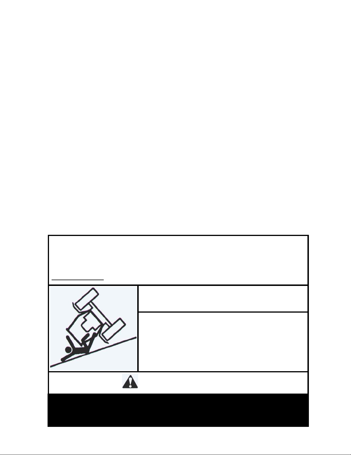
SERIOUS INJURY OR DEATH MAY RESULT FROM
• DO NOT OPERATE MACHINE ON STEEP SLOPES OR
NEAR DROP OFFS
• ALWAYS USE SEAT BELTS
• AVOID SHARP AND/OR QUICK TURNS
• DO NOT EXCEED THE MACHINE WEIGHT RATING OF
THE ROPS
WARNING!
MACHINE ROLLOVER
WARNING
ROLLOVER MAY CAUSE PERMANENT INJURY OR DEATH.
• ROPS RAISES THE CENTER OF GRAVITY AND REDUCES STABILITY ON SLOPES.
• SUDDEN STARTS OR TURNS ON RAMPS OR SLOPES CAN CAUSE OVERTURN.
• USE GREATER CARE ON RAMPS AND AS SLOPES INCREASE.
Page 3

Parts list
ITEM QTY PART NO. DESCRIPTION
1 1 98210002 WZ ROPS LEG WELDMENT, LH
2 1 98210003 WZ ROPS LEG WELDMENT, RH
3 1 98210004 WZ ROPS CENTER WELDMENT
4 1 98210005 WZ ROPS HARDWARE KIT
5 1 98210006 WZ ROPS SEAT BELT RETRACTOR
6 1 98210007 WZ ROPS SEAT BELT BUCKLE
7 8 11990093 HHCS, 7/16-14NC x 1.25 LG GR 5
8 8 12990009 HEX NYLOCK NUT, 7/16-14NC GR 5
9 4 13990002 FLAT WASHER, 7/16
10 2 3-10131 HHCS, 1/2-13NC x 3.00 LG GR 5
11 2 98210008 WZ ROPS LOCKING PIN
12 2 98210009 WZ ROPS FOAM WASHER
13 2 3-10485 HEX NUT, CENTERLOCK, 1/2-13NC
14 2 98210010 WZ ROPS LANYARD RETAINER
15 2 98210011 WZ ROPS NYLON LANYARD
16 6 11990032 HHCS, 3/8-16NC x 1.25 LG GR 5
17 6 12990020 HEX NYLOCK NUT, 3/8-16NC GR 5
18 1 98210012 WZ ROPS MOUNTING INSTRUCTIONS
19 1 98210012 WZ ROPS BUMPER
Page 4

Machine Preparation
1. Park machine on a level surface and set brake.
2. Remove ROPS and hardware from shipping box and identify all parts using
the parts list noted above.
Lower ROPS Leg Tube Installation
3. Jack and secure rear of mower and remove rear tires.
4. Remove left side rear fuel tank bracket bolts. Support tank.
5. Place LH leg weldment against LH machine frame mounting location.
6. Secure using (3) 7/16-14NC x 1.25” long hex head bolts, (3) 7/16-14NC
nylock hex nuts, (3) 3/8-16NC x 1.25” long hex head bolts and (3) 3/8-16NC
nylock hex nuts. Tighten bolts and nuts later in these instructions. See
Figure 1.
7. Loosen high pressure hoses at the pump and swivel away from LH leg
weldment.
8. Remove right side rear fuel tank bracket bolts. Support tank.
9. Repeat step 5-7 for installing RH leg weldment to RH side of machine frame
mounting location. See figure 2.
Figure 2
Figure 1
Page 5

Upper ROPS Hoop Installation
10. Install upper roll bar hoop assembly. Secure each side of hoop with (1)
½-13NC x 3.00” long hex head bolt, (1) pin retainer washer and (1) ½-13NC
center locking hex nut, into the upper mount hole of the hoop bracket.
Tighten only until the nut makes contact with the hoop bracket. Do not over
tighten. Hoop should pivot freely up and down. See Figure 3.
11. Install (1) EPDM washer onto each hitch pin. Position the top hoop into the
up-right position and insert hitch pins. See Figure 3.
Figure 3
12. Attach (1) nylon lanyard to the handle part of each hitch pin. Insert one end
of the lanyard through the retaining washer and attach to hitch pin spring
clip to the eye in the lanyard. Install the spring into the hitch pin. See
Figures 4, 5 and 6.
Figure 4 Figure 5 Figure 6
Page 6

13. Torque 7/16” lower leg mounting hardware to 59 ft-lbs and 3/8” hardware to
37 ft lbs.
Seatbelt Installation
14. Secure retractable seat belt using (2) 7/16-14NC x 1.25” long hex head
bolts, (4)7/16” flat washers and (2) 7/16-14NC nylock hex nuts. See figures
7 and 8.
Figure 7 Figure 8
Wright Manufacturing, Inc.
4600X Wedgewood Boulevard
Frederick, MD 21703
http://www.wrightmfg.com
 Loading...